US8646969B2 - Apparatus and methods for temperature calibration and sensing - Google Patents
Apparatus and methods for temperature calibration and sensingDownload PDFInfo
- Publication number
- US8646969B2 US8646969B2US13/470,790US201213470790AUS8646969B2US 8646969 B2US8646969 B2US 8646969B2US 201213470790 AUS201213470790 AUS 201213470790AUS 8646969 B2US8646969 B2US 8646969B2
- Authority
- US
- United States
- Prior art keywords
- state
- switch
- current
- node
- value
- Prior art date
- Legal status (The legal status is an assumption and is not a legal conclusion. Google has not performed a legal analysis and makes no representation as to the accuracy of the status listed.)
- Active
Links
Images


Classifications
- G—PHYSICS
- G01—MEASURING; TESTING
- G01K—MEASURING TEMPERATURE; MEASURING QUANTITY OF HEAT; THERMALLY-SENSITIVE ELEMENTS NOT OTHERWISE PROVIDED FOR
- G01K15/00—Testing or calibrating of thermometers
- G—PHYSICS
- G01—MEASURING; TESTING
- G01K—MEASURING TEMPERATURE; MEASURING QUANTITY OF HEAT; THERMALLY-SENSITIVE ELEMENTS NOT OTHERWISE PROVIDED FOR
- G01K15/00—Testing or calibrating of thermometers
- G01K15/005—Calibration
- G—PHYSICS
- G01—MEASURING; TESTING
- G01K—MEASURING TEMPERATURE; MEASURING QUANTITY OF HEAT; THERMALLY-SENSITIVE ELEMENTS NOT OTHERWISE PROVIDED FOR
- G01K7/00—Measuring temperature based on the use of electric or magnetic elements directly sensitive to heat ; Power supply therefor, e.g. using thermoelectric elements
- G01K7/01—Measuring temperature based on the use of electric or magnetic elements directly sensitive to heat ; Power supply therefor, e.g. using thermoelectric elements using semiconducting elements having PN junctions
Definitions
- Semiconductor devicessuch as memory devices and processors, can often operate at different temperatures. These devices may have a temperature sensor within the device to allow them to adjust some of their operations based on temperature readings provided by the temperature sensor.
- Conventional temperature sensorsmay provide relatively accurate temperature readings within a specific temperature range. However, outside the specific temperature range, some conventional temperature sensors may provide temperature readings with reduced accuracy.
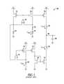
- FIG. 1shows a prior art first order delta sigma temperature sensor.
- FIG. 2shows a temperature sensor according to an embodiment of the invention.
- FIG. 3shows a temperature sensor having a tap control unit according to an embodiment of the invention.
- FIG. 4is a flowchart showing methods of calibrating a temperature sensor according to an embodiment of the invention.
- FIG. 5shows a block diagram of a device including a temperature sensor according an embodiment of the invention.
- FIG. 1shows a prior art first order delta sigma temperature sensor 100 .
- Temperature sensor 100includes transistors 111 , 112 , 113 , 114 , 115 , 116 , and 117 , resistors 121 and 122 , amplifiers 131 and 132 , diodes 141 and 142 , capacitor 145 , and switches 151 and 152 .
- Temperature sensor 100may provide a temperature reading based on the value of a current I PTAT (proportional temperature absolute temperature) flowing through diode 142 and the value of a current I CTAT (complimentary temperature absolute temperature) flowing through resistor 122 .
- Current I PTAThas a positive temperature coefficient, and increases as temperature increases.
- Current I CTAThas a negative temperature coefficient and decreases when the temperature decreases.
- each of switches 151 and 152may switch between the on-state (to allow conduction of current through the switch) and the off-state (to prevent conduction of current through the switch) based on currents I PTAT and I CTAT to allow temperature sensor 100 to provide an appropriate temperature reading. For example, when the voltage at node 199 is less than VCC/2 (one-half of supply voltage), switch 151 may switch to the on-state and switch 152 may switch to the off-state. Current I PTAT may flow between transistor 113 and node 199 and raise the value of the voltage at node 199 . When the value of the voltage at node 199 is greater than VCC/2, switch 151 may switch to the off-state and switch 152 may switch to the on-state.
- VCC/2one-half of supply voltage
- Current I CTATmay flow between node 199 and transistor 117 and lower the value of the voltage at node 199 .
- the switching of switches 151 and 152may keep the voltage at the node 199 at a relatively constant value for the operation of temperature sensor 100 .
- the current across switch 151is equal to (100 ⁇ X) % I PTAT and the current across switch 152 is equal to X % I CTAT , where X is a number from 0 to 100. Since the value of the voltage at 199 is relatively constant, the average current across switch 151 may be assumed to be equal to the average current across switch 152 .
- X % I CTAT(100 ⁇ X) % I PTAT .
- Temperature sensor 100may use the percentage relationship between I PTAT and I CTAT in its calculation to provide the temperature reading.
- Temperature sensor 100may provide the temperature reading Temp based on equation (1) below.
- Temprepresents the value of the temperature reading and has a unit in degree Celsius (° C.).
- Numbererofclocksrepresents the number of cycles of a clock signal corresponding to specific time interval that temperature sensor 100 operates to provide each temperature reading. The number of cycles of the clocks may be fixed for temperature sensor 100 .
- (I PTAT /(I PTAT +I CTAT )corresponds to (100 ⁇ X) % I PTAT , which corresponds to the number of times that switch 151 is in the on-state.
- DCoffsetrepresents an offset value, which can be obtained during a calibration of temperature sensor 100 .
- the value of the DCoffsetmay be calculated as follows. During a calibration, temperature sensor 100 may be brought to a calibration temperature, which is an expected value for Temp in equation (1) at one temperature point. Then, the value of ratio I PTAT /(I PTAT +I CTAT ) may be obtained by determining the percentage (the number of clock cycles) that switch 151 is in the on-state for a given time interval. This percentage may be obtained by counting the number of times that switch 151 switches between the on-state and the off-state.
- the value 300(which is 500*(60%)) may be obtained by counting the number of times that switch 151 switches between the on-state and the off-state.
- Equation (1) abovemay be rewritten as equation (2) below.
- nis a process variable, having a value approximately equal to one.
- Vtis the thermal voltage, about 25.6 millivolts (my) at room temp, and has a temperature coefficient about 0.085 mv/degree Celsius. The value of Vt may increase when the temperature increases.
- Kis the ratio of the sizes of diodes 142 and 141 .
- I CTATis the current across resistor 122 .
- LR 2 /R 1 , where R 1 is the resistive value of resistor 121 and R 2 is the resistive value of resistor 122 .
- Vdis the diode forward biasing voltage of diode 141 and has a temperature coefficient of about ⁇ 1.6 mv/degree Celsius at a typical process corner.
- Vdmay vary from ⁇ 1.5 mV to ⁇ 1.7 mV/degree Celsius when the process varies.
- the term (Vd*n*Vt*lnK*L)may vary with temperature.
- the temperature readings provided by temperature sensor 100may also vary at some temperature range.
- the conventional one-point calibration techniquemay allow a conventional temperature sensor, such as temperature sensor 100 , to provide relatively accurate temperature readings within a specific temperature range around the calibration temperature (e.g., 90° C. used in the example above) when the diode (e.g., diode 141 or diode 142 of FIG. 1 ) is at a typical process corner and has a temperature coefficient at a value such as ⁇ 1.6 mv/degree Celsius.
- the conventional temperature sensor and calibration techniquemay provide relatively reduced accurate temperature readings for a wider temperature range when process varies and the diode temperature coefficient changes from the typical ⁇ 1.6 mv/degree Celsius. For example, when calibrated at a calibration temperature (e.g., 90° C.), temperature sensor 100 of FIG.
- temperature sensor 100may provide relatively accurate temperature readings within a temperature range of 80° C. to 100° C. However, for a different temperature range (e.g., 0° C. to 125° C.), temperature sensor 100 may give some temperature readings (e.g., temperature readings between 0° C. and 80° C. and between 100° C. and 125° C.) with reduced accuracy.
- FIG. 2shows a temperature sensor 200 according to an embodiment of the invention.
- Temperature sensor 200may provide relatively more accurate temperature readings for a relatively wider temperature range. For example, when calibrated at a temperature of 90° C., temperature sensor 200 may provide relatively more accurate temperature readings at a temperature range of 0° C. to 125° C. The calibration temperature of 90° C. and the temperature range of 0° C. to 125° C. are used as examples. Temperature sensor 200 may be calibrated at other calibration temperatures.
- Temperature sensor 200may provide temperature readings based on equation (3) below.
- I CTAT(Vd+I PTAT *x*R 1 )/(L*R 1 ) is placed in equation (3)
- equation (3)may be rewritten as equation (4) below.
- Equations (3) and (4)are similar to equations (1) and (2), respectively, except for an additional term (x*I PTAT ) in equation (3) or (x*n*Vt*lnK*L) in equation (4).
- equation (4)if the value of “x” is appropriately selected, then Vd*n*Vt*lnK*L+(x*n*Vt*lnK*L) may become constant to allow temperature sensor 200 to provide appropriate temperature readings.
- “x”may be called a calibration coefficient, which may be negative or positive.
- Calibration coefficient “x”may have a value equal to 0 at a typical diode process corner. However, as discussed above with reference to FIG. 1 , the process may vary and the diode temperature coefficient may change from the typical ⁇ 1.6 mv/degree Celsius. Without calibration coefficient “x”, the accuracy of the temperature readings may be reduced for some temperature ranges.
- the addition of calibration coefficient “x” in equation (3) and (4)may allow options to adjust the components of the temperature sensor, such as temperature sensor 200 , during calibration so that the temperature sensor may provide relatively more accurate temperature readings for a relatively wider temperature range after the calibration.
- the value for calibration coefficient “x”may be determined by adjusting the components of temperature sensor 200 , such as adjusting the connections at taps 281 , 282 , 283 , 284 , 285 , 286 , and 287 ( FIG. 2 ), during a calibration to change the value of current I CTAT until the value of a temperature reading during the calibration matches the value of the calibration temperature.
- Calibration coefficient “x”may have a value of approximately ⁇ 0.1 to 0.1 for a calibration temperature 90° C., for example. Adjusting the connections at taps 281 through 287 is described in more detail below. After the value of calibration coefficient “x” is determined, taps 281 through 287 may be set to a configuration to allow temperature sensor 200 to provide temperature readings based on equation (4).
- temperature sensor 200may also include transistors 211 , 212 , and 213 , amplifier 214 , diode 208 , and a resistors 221 , 222 , 223 , 224 , 225 , 226 , and 227 , and a connector 290 .
- Taps 281 through 287may be located among resistors 221 through 227 .
- Connector 290may be coupled between one of taps 281 through 287 and amplifier input node 238 of an amplifier 235 .
- FIG. 2shows seven resistors 221 through 227 and seven taps 281 through 287 on a circuit path 241 as an example. The number of resistors and taps on circuit path 241 may vary.
- Resistors 221 through 227may be coupled in series with diode 208 on circuit path 241 between supply nodes 204 and 205 , which may be coupled to a supply voltage VCC and a ground potential, respectively.
- Diode 207may be coupled to resistors 221 through 227 and diode 208 in a current minor circuit arrangement as shown in FIG. 2 to cause the value of current I PTAT to be dependent on the value of a current I D flowing through diode 207 .
- Current I PTAThas a positive temperature coefficient.
- Transistors 211 , 212 , and 213 , amplifier 214 , diodes 207 and 208 , and resistors 221 through 227may form a current mirror to minor current I PTAT to a circuit path 242 as current I PTAT2 , such that current I PTAT2 may have a value dependent on the value of current I PTAT .
- the value of current I PTAT2may be equal to the value of current I PTAT when transistors 211 , 212 , and 213 have the same size.
- Temperature sensor 200may include transistors 231 , 232 , 233 , and 234 , and a resistor 236 .
- Resistor 236may be coupled on a circuit path 243 between a node 237 and supply node 205 to carry current I CTAT .
- Current I CTAThas a negative temperature coefficient.
- Transistors 231 through 234 , amplifier 235 , and resistor 236may form a current mirror to minor current I CTAT to a circuit path 244 as current I CTAT2 , such that current I CTAT2 may have a value dependent on the value of current I PTAT .
- the value of current I CTAT2may be equal to the value of current I CTAT when transistors 231 , 223 , 233 , and 234 have the same size.
- Amplifier 235may include an operational amplifier such that the value of the voltage at amplifier input node coupled to node 237 is equal or substantially equal to the value of the voltage at amplifier input node 238 .
- current I CTATmay also be a function of a voltage at node 238 and a resistance on circuit path 243 .
- current I CTATmay also be a function of the voltage at a selected one of taps 281 through 287 (voltage at a node between two of resistors 221 through 227 where the selected tap is located) and a resistance of circuit path 243 .
- Temperature sensor 200may include switches 251 and 252 .
- Switch 251may switch between the on-state and the off-state to control a conduction of current I PTAT2 on circuit path 242 , which is coupled between node 299 and supply node 204 .
- Switch 252may switch between the on-state and the off-state to control a conduction of current I CTAT2 on circuit path 244 , which is coupled between node 299 and supply node 205 .
- Temperature sensor 200may include a circuit 270 to provide a temperature reading Temp based on the signal at the node 299 .
- Circuit 270may include a comparator 271 , a capacitor 272 , and an inverter 273 to switch the switch 251 to the off-state and the switch 252 to the on-state when a value of the signal node 299 exceeds the value of a voltage Vcmp.
- Circuit 270may switch the switch 251 to the on-state and the switch 252 to the off-state when a value of the signal node 299 is below the value of voltage Vcmp.
- voltage Vcmpmay have a value of one-half of supply voltage VCC.
- Voltage Vcmpmay have another voltage value.
- Circuit 270may also include a counter 274 to provide a count and a temperature readout unit 275 to provide the temperature reading Temp based on the count.
- Each of switches 251 and 252may switch between the on-state and the off-state for a number of times based on the values of current I PTAT2 and current I CTAT2 during a time interval, which may correspond to a number of clock cycles of a clock signal such as the CLK signal.
- currents I PTAT2 and I CTAT2may have values dependent on (e.g., equal to) the values of currents I PTAT and current I CTAT , respectively.
- switches 251 and 252may switch between the on-state and the off-state based on the values of currents I PTAT and I CTAT .
- the value of the signal at node 299may change between different values (e.g., different voltage values) when switches 251 and 252 switch between the on-state and the off-state.
- Comparator 271may be enabled one time during each cycle of the CLK signal, e.g., at the rising edge of the CLK signal. Comparator 271 may sense the change in values at node 299 to appropriately cause the signal at the output of inverter 273 to change. For example, the signal at the output of inverter 273 may have a lower voltage value when the value at node 299 exceeds the value of voltage Vcmp. In another example, the signal at the output of inverter 273 may have a higher voltage value when the value at node 299 is below the value of voltage Vcmp.
- counter 274may count the number of times one of the switches 251 and 252 (e.g., switch 251 ) switches between the on-state and the off-state during the time interval.
- Temperature readout unit 275may use the count and translate it into a temperature value (value of Temp) using equation (3). For example, temperature readout unit 275 may subtract an offset value (such as the value of DCoffset in equation (3)) above from the count to provide the value of the temperature reading. The value of the offset may be obtained during a calibration of temperature sensor 200 .
- FIG. 2shows amplifier input node 238 being coupled to tap 282 as an example.
- Amplifier input node 238may be coupled to a different tap, depending on the result of a calibration of temperature sensor 200 , as described below.
- the value of current I CTATmay be changed to an appropriate value to allow temperature sensor 200 to be calibrated to a calibration temperature.
- current I CTATis a function of the voltage at node 237 and the resistance on circuit path 243 .
- the value of current I CTATmay be changed by changing the value of the voltage at node 237 . Since amplifier input node coupling to node 237 is equal to, or substantially equal to, the value of the voltage at amplifier input node 238 , the value of the voltage at node 237 may be changed by changing the value of the voltage at amplifier input node 238 . As shown in FIG.
- the arrangement of taps 281 through 287 among resistors 221 through 227may allow taps 281 through 287 to have different voltage values.
- connecting amplifier input node 238 to a different tap during calibration of temperature sensor 200may cause amplifier input node 238 to have a different voltage value to change the value of I CTAT during a calibration of temperature sensor 200 .
- the calibration of temperature sensor 200may start by bringing temperature sensor 200 to a calibration temperature (e.g., 90° C.). Then, tap control unit 276 may connect amplifier input node 238 to taps 281 through 287 , via connector 290 , one tap at a time. For example, tap control unit 276 may connect amplifier input node 238 to tap 281 via connector 290 for a time interval, then it may disconnect amplifier input node 238 from tap 281 and connect amplifier input node 238 to tap 282 via connector 290 for another time interval. Tap control unit 276 may continue with other taps in a similar way. Tap control unit 276 may connect amplifier input node 238 to some or all of taps 281 through 287 .
- a calibration temperaturee.g. 90° C.
- a temperature readingmay be obtained (e.g., using circuit 270 ). Thus, a number of temperature readings may be obtained.
- the calibrationmay identify a selected tap among taps 281 through 287 that results in temperature sensor 200 providing a temperature reading with a value equal or closest to the value of the calibration temperature. For example, if the calibration temperature is 90° C., then the calibration may identify the tap (selected tap) that results in temperature sensor 200 providing a temperature reading with a value of 90° C. or a value closest to 90° C.
- FIG. 2shows connector 290 being connected between amplifier input node 238 and tap 282 to indicate an example that tap 282 is the selected tap, which is the tap that results in temperature sensor 200 providing reading with a value equal or closest to the value of a calibration temperature during a calibration temperature sensor 200 .
- the calibrationmay continue with setting temperature sensor 200 to a configuration such that the configuration may allow connector 290 to connect amplifier input node 238 to only the selected tap when temperature sensor 200 operates in a normal operation (e.g., the operation after the calibration).
- Connector 290may include a passive element, such as conductive line or trace, to form a conductive connection between amplifier input node 238 and the selected tap (after the selected tap is identified by the calibration). Connector 290 may also include non-passive elements such as transistors. For example, when connector 290 is a transistor, the transistor may turn on to form a conductive connection between amplifier input node 238 and the selected tap via the transistor.
- Control unit 276may include features such as logic circuitry, decoder, and/or antifuse circuits to set temperature sensor 200 to a configuration to allow temperature sensor 200 to connect amplifier input node 238 to the appropriate tap (e.g., the selected tap) to provide appropriate temperature readings.
- FIG. 3shows a temperature sensor 300 having a tap control unit 376 according to an embodiment of the invention.
- Temperature sensor 300may include features similar to those of temperature sensor 200 of FIG. 2 , except for transistors 301 , 302 , 303 , 304 , 305 , 306 , and 307 , and tap control unit 376 of FIG. 3 . Thus, for simplicity similar features between FIG. 2 and FIG. 3 have the same reference labels.
- each of transistors 301 through 307may include a terminal (e.g., source or drain) coupled to one of taps 381 , 382 , 383 , 384 , 385 , 386 , and 387 , a terminal (e.g., source or drain) coupled to an amplifier input node 338 of amplifier 335 , and a gate coupled to tap control unit 376 .
- Temperature sensor 300may be calibrated in ways similar to or identical to that of temperature sensor 200 of FIG. 2 . For example, during a calibration of temperature sensor 300 , one of taps 381 through 387 may be identified as the selected tap that results in temperature sensor 300 providing a temperature reading with a value equal or closest to the value of the calibration temperature.
- Tap control unit 376may include a decoder 375 and antifuse circuits 377 , 378 , and 379 to set temperature sensor 300 to a configuration to allow it to connect amplifier input node 338 to the selected tap when temperature sensor 300 operates to provide temperature readings in an operation (e.g., normal operation) after the calibration. For example, if tap 382 is identified as the selected tap during the calibration, then, during a normal operation, tap control unit 376 turns on only transistor 302 and turns off the other transistors 301 and 303 through 307 , so that only transistor 302 forms a conductive connection to connect amplifier input node 338 to tap 382 while the other taps ( 381 and 383 through and 387 ) remain non-conductive.
- tap control unit 376may include a decoder 375 and antifuse circuits 377 , 378 , and 379 to set temperature sensor 300 to a configuration to allow it to connect amplifier input node 338 to the selected tap when temperature sensor 300 operates to provide temperature readings in an operation (e.
- Each of antifuse circuits 377 , 378 , and 379may have an open-state to prevent a conduction of current through it, and a close-state to allow a conduction of current through it.
- Tap control unit 376may use the combination of open and close states of antifuse circuits 377 , 378 , and 379 to control decoder 375 such that decoder 375 may activate only one of the signals at the gates of transistors 301 through 307 to turn on only the transistor that couples to the selected tap (one of taps 381 through 387 ).
- antifuse circuits 377 , 378 , and 379may provide eight different combinations to control up to eight different transistors, such as transistors 301 through 307 .
- each of antifuse circuits 377 , 378 , and 379may be put in the open or close state to provide an appropriate combination.
- the state of antifuse circuit 377 , 378 , or 379may be changed from the open-state to the close-state by “burning” the antifuse.
- tap control unit 376may turn on only one of the transistors 301 through 307 so that temperature sensor 300 may provide appropriate temperature readings.
- FIG. 4is a flowchart showing methods 400 of calibrating a temperature sensor according to an embodiment of the invention.
- Methods 400may be used to calibrate a temperature sensor such as temperature sensors 200 and 300 of FIG. 2 and FIG. 3 .
- the components used in methods 400may include components similar to or identical to those of temperature sensors 200 and 300 of FIG. 2 and FIG. 3 .
- methods 400may start at activity 410 , which may include bringing the temperature sensor to a calibration temperature for the calibration.
- Activity 420may include connecting a node from first circuit portion of the temperature sensor to a number of taps coupled to a number of resistors of the temperature sensor. The node may be connected to the taps one at a time.
- Activity 430may include obtaining a number of temperature readings. Each of the temperature readings may be obtained when the node is connected to a different tap among the taps.
- Activity 440may include setting the temperature sensor to a configuration that may allow the temperature sensor to connect the node to a selected tap when the temperature sensor operates after the calibration. The selected tap is one of the taps that results in the temperature sensor providing a temperature reading with a value equal or closest to the value of the calibration temperature during the calibration.
- Methods 400may include other activities similar to or identical to the activities of temperature sensors 200 and 300 of FIG. 2 and FIG. 3 .
- FIG. 5shows a block diagram of a device 500 having a temperature sensor 501 according to an embodiment of the invention.
- Device 500may include a memory device such as a volatile memory device, a non-volatile memory device, or a combination of both.
- device 500may include a dynamic random access memory (DRAM) device, a static random access memory (SRAM) device, a flash memory device, a phase change memory device, or a combination of these memory devices.
- DRAMdynamic random access memory
- SRAMstatic random access memory
- flash memory devicea phase change memory device, or a combination of these memory devices.
- Device 500may also include a general purpose processor, an application specific integrated circuit, or other electronic devices.
- device 500may include a memory array 510 having memory cells 511 to store data and other information, and an input/output (I/O) circuit 504 to transfer data and information (represented by signals DATA) to and from device 500 .
- Device 500may include a memory control unit 505 to control its operations in response to signals such as control signals (CTL), address signals (ADDR), and clock signal (CLK).
- Operations of device 500may include a read operation to read information from memory cells 511 , a write operation to write information into memory cells 511 , and a refresh operation to refresh memory cells 511 .
- memory cells 511include volatile memory cells such as DRAM cells, charge representing the value of information stored in memory cells 511 may leak.
- the charge leakagemay degrade the value of information stored in memory cells 511 or cause the information to become invalid.
- Device 500may perform the refresh operation to keep the charge in memory cells 511 at an appropriate level to maintain the validity of the information stored in memory cells 511 .
- Device 500may refresh memory cells 511 at a refresh rate, which may depend on the temperature of device 500 .
- Temperature sensor 501may sense the temperature of device 500 to provide temperature readings. Temperature sensor 501 may include temperature sensors 200 and 300 of FIG. 2 and FIG. 3 . Thus, temperature sensor 501 may include a temperature sensor calibration and temperature reading operation similar to or identical to the calibration and temperature reading operation described above with reference to FIG. 2 through FIG. 4 . In FIG. 5 , based on the temperature readings provided by temperature sensor 501 , device 500 may adjust some of its operations. For example, device 500 may adjust the refresh rate to avoid over refreshing or under refreshing of memory cells 511 when the temperature changes.
- Device 500may include a refresh controller 530 to control the refresh operation and the refresh rate based on temperature readings provided by temperature sensor 501 .
- the amount of charge leakage from memory cells 511is proportional to the temperature of device 500 .
- the amount of charge leakageincreases when the temperature increases and decreases when the temperature decreases.
- refresh controller 530may refresh memory cells 511 at a refresh rate that is proportional to the values of the temperature readings. For example, refresh controller 530 may refresh memory cells 511 at a higher refresh rate (refresh more often) when the temperature increases and at a lower refresh rate when the temperature decreases.
- device 500may include other features that are not shown in FIG. 5 to help focus on the embodiments described herein.
- apparatuse.g., temperature sensors 200 , 300 , and 501 and device 500
- modulesmay include hardware circuitry, single and/or multi-processor circuits, memory circuits, software program modules and objects and/or firmware, and combinations thereof, as desired by the architect of the apparatus (e.g., temperature sensors 200 , 300 , and 501 and device 500 ), and as appropriate for particular implementations of various embodiments.
- modulesmay be included in a system operation simulation package, such as a software electrical signal simulation package, a power usage and distribution simulation package, a capacitance-inductance simulation package, a power/heat dissipation simulation package, a signal transmission-reception simulation package, and/or a combination of software and hardware used to operate or simulate the operation of various potential embodiments.
- a system operation simulation packagesuch as a software electrical signal simulation package, a power usage and distribution simulation package, a capacitance-inductance simulation package, a power/heat dissipation simulation package, a signal transmission-reception simulation package, and/or a combination of software and hardware used to operate or simulate the operation of various potential embodiments.
- the apparatuse.g., temperature sensors 200 , 300 , and 501 and device 500 of various embodiments may include or be included in electronic circuitry used in high-speed computers, communication and signal processing circuitry, single or multi-processor modules, single or multiple embedded processors, multi-core processors, data switches, and application-specific modules including multilayer, multi-chip modules.
- Such apparatusmay further be included as sub-components within a variety of electronic systems, such as televisions, cellular telephones, personal computers (e.g., laptop computers, desktop computers, handheld computers, tablet computers, etc.), workstations, radios, video players, audio players (e.g., MP3 (Motion Picture Experts Group, Audio Layer 3) players), vehicles, medical devices (e.g., heart monitor, blood pressure monitor, etc.), set top boxes, and others.
- televisionse.g., laptop computers, desktop computers, handheld computers, tablet computers, etc.
- workstationse.g., radios, video players, audio players (e.g., MP3 (Motion Picture Experts Group, Audio Layer 3) players), vehicles, medical devices (e.g., heart monitor, blood pressure monitor, etc.), set top boxes, and others.
- video playerse.g., laptop computers, desktop computers, handheld computers, tablet computers, etc.
- audio playerse.g., MP3 (Motion Picture Experts Group, Audio
- One or more embodiments described hereininclude apparatus and methods having a first switch, a second switch, and a circuit coupled to the first and second switches.
- the first switchmay be configured to switch between an on-state and an off-state based on a value of a first current flowing through a number of resistors and a diode coupled in series with the resistors.
- the second switchmay be configured to switch between the on-state and the off-state based on a value of a second current on a circuit path.
- the second currentis a function of a voltage at a node between two of the resistors and a resistance of the circuit path.
- the circuitmay be configured to provide a temperature reading based on the number of times the first switch or the second switch switches between the on-state and the off-state during a time interval.
- Other embodiments, including additional apparatus and methodsare described above with reference to FIG. 2 through FIG. 5 .
Landscapes
- Physics & Mathematics (AREA)
- General Physics & Mathematics (AREA)
- Measuring Temperature Or Quantity Of Heat (AREA)
Abstract
Description
Claims (20)
Priority Applications (1)
| Application Number | Priority Date | Filing Date | Title |
|---|---|---|---|
| US13/470,790US8646969B2 (en) | 2008-03-19 | 2012-05-14 | Apparatus and methods for temperature calibration and sensing |
Applications Claiming Priority (3)
| Application Number | Priority Date | Filing Date | Title |
|---|---|---|---|
| US12/051,737US7896545B2 (en) | 2008-03-19 | 2008-03-19 | Apparatus and methods for temperature calibration and sensing |
| US13/035,805US8177420B2 (en) | 2008-03-19 | 2011-02-25 | Apparatus and methods for temperature calibration and sensing |
| US13/470,790US8646969B2 (en) | 2008-03-19 | 2012-05-14 | Apparatus and methods for temperature calibration and sensing |
Related Parent Applications (1)
| Application Number | Title | Priority Date | Filing Date |
|---|---|---|---|
| US13/035,805ContinuationUS8177420B2 (en) | 2008-03-19 | 2011-02-25 | Apparatus and methods for temperature calibration and sensing |
Publications (2)
| Publication Number | Publication Date |
|---|---|
| US20120224605A1 US20120224605A1 (en) | 2012-09-06 |
| US8646969B2true US8646969B2 (en) | 2014-02-11 |
Family
ID=41088889
Family Applications (3)
| Application Number | Title | Priority Date | Filing Date |
|---|---|---|---|
| US12/051,737Active2029-07-18US7896545B2 (en) | 2008-03-19 | 2008-03-19 | Apparatus and methods for temperature calibration and sensing |
| US13/035,805ActiveUS8177420B2 (en) | 2008-03-19 | 2011-02-25 | Apparatus and methods for temperature calibration and sensing |
| US13/470,790ActiveUS8646969B2 (en) | 2008-03-19 | 2012-05-14 | Apparatus and methods for temperature calibration and sensing |
Family Applications Before (2)
| Application Number | Title | Priority Date | Filing Date |
|---|---|---|---|
| US12/051,737Active2029-07-18US7896545B2 (en) | 2008-03-19 | 2008-03-19 | Apparatus and methods for temperature calibration and sensing |
| US13/035,805ActiveUS8177420B2 (en) | 2008-03-19 | 2011-02-25 | Apparatus and methods for temperature calibration and sensing |
Country Status (1)
| Country | Link |
|---|---|
| US (3) | US7896545B2 (en) |
Cited By (1)
| Publication number | Priority date | Publication date | Assignee | Title |
|---|---|---|---|---|
| US20130272340A1 (en)* | 2009-04-22 | 2013-10-17 | Taiwan Semiconductor Manufacturing Company, Ltd. | Temperature sensing circuit |
Families Citing this family (26)
| Publication number | Priority date | Publication date | Assignee | Title |
|---|---|---|---|---|
| US7405552B2 (en)* | 2006-01-04 | 2008-07-29 | Micron Technology, Inc. | Semiconductor temperature sensor with high sensitivity |
| US7887235B2 (en)* | 2006-08-30 | 2011-02-15 | Freescale Semiconductor, Inc. | Multiple sensor thermal management for electronic devices |
| US7816973B2 (en)* | 2007-11-20 | 2010-10-19 | Micron Technology, Inc. | Devices and methods for reducing effects of device mismatch in temperature sensor circuits |
| KR101007988B1 (en)* | 2008-01-02 | 2011-01-14 | 주식회사 하이닉스반도체 | Temperature information output circuit and multichip package using the same |
| US7896545B2 (en)* | 2008-03-19 | 2011-03-01 | Micron Technology, Inc. | Apparatus and methods for temperature calibration and sensing |
| TWI372855B (en)* | 2008-05-27 | 2012-09-21 | Nanya Technology Corp | Temperature detector and the method using the same |
| JP5144559B2 (en)* | 2008-08-29 | 2013-02-13 | セイコーインスツル株式会社 | Two-terminal type semiconductor temperature sensor |
| TWI384210B (en)* | 2009-08-14 | 2013-02-01 | Sunplus Technology Co Ltd | Thermal detecting apparatus and method |
| US8556505B2 (en)* | 2009-09-18 | 2013-10-15 | Cummins Ip, Inc. | Apparatus, system, and method for accurately reading high and low temperatures |
| US8292502B2 (en) | 2010-04-07 | 2012-10-23 | Arizant Healthcare Inc. | Constructions for zero-heat-flux, deep tissue temperature measurement devices |
| US8292495B2 (en)* | 2010-04-07 | 2012-10-23 | Arizant Healthcare Inc. | Zero-heat-flux, deep tissue temperature measurement devices with thermal sensor calibration |
| JP5635935B2 (en)* | 2011-03-31 | 2014-12-03 | ルネサスエレクトロニクス株式会社 | Constant current generation circuit, microprocessor and semiconductor device including the same |
| US9354122B2 (en) | 2011-05-10 | 2016-05-31 | 3M Innovative Properties Company | Zero-heat-flux, deep tissue temperature measurement system |
| US9041353B2 (en) | 2011-08-18 | 2015-05-26 | Taiwan Semiconductor Manufacturing Company, Ltd. | Battery fuel gauge apparatus |
| US8971123B2 (en) | 2012-01-13 | 2015-03-03 | Sandisk Il Ltd | Memory system temperature calibration |
| US10241717B2 (en)* | 2013-12-30 | 2019-03-26 | Qualcomm Technologies International, Ltd. | Memory boosting |
| US9594390B2 (en)* | 2014-11-26 | 2017-03-14 | Taiwan Semiconductor Manufacturing Company Limited | Voltage reference circuit |
| US10151644B2 (en) | 2015-03-13 | 2018-12-11 | Taiwan Semiconductor Manufacturing Company Limited | Combination current generator configured to selectively generate one of a PTAT and a CTAT current |
| DE102016206447B3 (en)* | 2016-04-15 | 2017-08-10 | Sirona Dental Systems Gmbh | Method for calibrating a temperature measuring device of a dental oven and calibrating body |
| US10768057B2 (en) | 2017-03-30 | 2020-09-08 | Oracle International Corporation | Statistical temperature sensor calibration apparatus and methodology |
| US11056164B2 (en)* | 2019-02-05 | 2021-07-06 | Arm Limited | Circuits to control output signal variability |
| CN109798999B (en)* | 2019-02-27 | 2019-11-15 | 南京瑞贻电子科技有限公司 | A double galvanic couple temperature measuring device |
| TWI727673B (en)* | 2020-02-25 | 2021-05-11 | 瑞昱半導體股份有限公司 | Bias current generation circuit |
| CN113483919B (en)* | 2021-06-30 | 2024-06-11 | 启北公司 | A temperature calibration method, system, storage medium and electronic device |
| US11830540B2 (en)* | 2021-12-12 | 2023-11-28 | Nanya Technology Corporation | Circuit for sensing antifuse of DRAMs |
| CN114357234B (en)* | 2021-12-27 | 2025-06-27 | 星河智联汽车科技有限公司 | In-vehicle audio recommendation method, device and vehicle |
Citations (29)
| Publication number | Priority date | Publication date | Assignee | Title |
|---|---|---|---|---|
| US2993377A (en) | 1958-04-07 | 1961-07-25 | Ca Nat Research Council | Direct reading resistance thermometer |
| US3077775A (en) | 1958-06-10 | 1963-02-19 | Bailey Meter Co | Scanning apparatus |
| US3485102A (en) | 1967-04-17 | 1969-12-23 | Allied Precision Lab Inc | Electronic temperature measuring device |
| US3722283A (en) | 1971-11-17 | 1973-03-27 | Kettering Scient Res Inc | Linear reading thermometer |
| US3890836A (en) | 1973-10-15 | 1975-06-24 | Draf Tool Co Inc | Automatic temperature control system analyzer |
| US3902351A (en) | 1971-10-04 | 1975-09-02 | Robertshaw Controls Co | Thermostatic control calibration apparatus |
| US4216675A (en) | 1978-04-29 | 1980-08-12 | Omron Tateisi Electronics Co. | Temperature detecting device |
| US5149199A (en)* | 1990-05-24 | 1992-09-22 | Kabushiki Kaisha Toshiba | Temperature detection circuit used in thermal shielding circuit |
| US5171091A (en) | 1989-10-05 | 1992-12-15 | Endress U. Hauser Gmbh U. Co. | Temperature measuring circuit |
| US5669713A (en) | 1994-09-27 | 1997-09-23 | Rosemount Inc. | Calibration of process control temperature transmitter |
| US5993060A (en) | 1997-01-14 | 1999-11-30 | Citizen Watch Co., Ltd. | Temperature sensor and method of adjusting the same |
| US20010026576A1 (en)* | 2000-03-08 | 2001-10-04 | Peter Beer | Method for determining the temperature of a semiconductor chip and semiconductor chip with temperature measuring configuration |
| US6554469B1 (en) | 2001-04-17 | 2003-04-29 | Analog Devices, Inc. | Four current transistor temperature sensor and method |
| US20030118079A1 (en) | 2001-12-21 | 2003-06-26 | Stmicroelectronics S.A. | Threshold temperature sensor comprising room temperature test means |
| US20040071191A1 (en) | 2002-08-09 | 2004-04-15 | Jae-Yoon Sim | Temperature sensor and method for detecting trip temperature of a temperature sensor |
| US20040071189A1 (en) | 2002-10-09 | 2004-04-15 | Nec Electronics Corporation | Temperature measuring sensor incorporated in semiconductor substrate, and semiconductor device containing such temperature measuring sensor |
| US6733174B2 (en)* | 2000-08-04 | 2004-05-11 | Nippon Precision Circuits Inc. | Semiconductor temperature detecting method and its circuit |
| US20040208225A1 (en) | 2003-03-18 | 2004-10-21 | Yuzuru Otsuka | Method and apparatus for correcting sensor signal in temperature |
| US6934645B2 (en) | 2003-09-25 | 2005-08-23 | Infineon Technologies Ag | Temperature sensor scheme |
| US6957910B1 (en)* | 2004-01-05 | 2005-10-25 | National Semiconductor Corporation | Synchronized delta-VBE measurement system |
| US20060071189A1 (en) | 2004-10-04 | 2006-04-06 | R. Conrader Company | Pressure relief valve |
| US20060267668A1 (en) | 2004-08-31 | 2006-11-30 | Porter J D | Method, apparatus, and system for low voltage temperature sensing |
| US7252432B1 (en)* | 2004-10-27 | 2007-08-07 | National Semiconductor Corporation | Efficient method of sharing diode pins on multi-channel remote diode temperature sensors |
| US20070189355A1 (en) | 2006-02-16 | 2007-08-16 | Harald Lorenz | Method and apparatus for calibration of an on-chip temperature sensor within a memory device |
| US20090046761A1 (en)* | 2007-08-16 | 2009-02-19 | Micron Technology, Inc. | Temperature sensor circuit, device, system, and method |
| US20090238239A1 (en) | 2008-03-19 | 2009-09-24 | Micron Technology, Inc. | Apparatus and methods for temperature calibration and sensing |
| US20100002748A1 (en)* | 2006-10-21 | 2010-01-07 | Intersil Americas Inc. | Cmos temperature-to-digital converter with digital correction |
| US20110006831A1 (en) | 2007-11-20 | 2011-01-13 | Micron Technology, Inc. | Devices and methods for reducing effects of device mismatch in temperature sensor circuits |
| US20130120930A1 (en)* | 2011-11-15 | 2013-05-16 | Grigori Temkine | Dynamic voltage reference for sampling delta based temperature sensor |
- 2008
- 2008-03-19USUS12/051,737patent/US7896545B2/enactiveActive
- 2011
- 2011-02-25USUS13/035,805patent/US8177420B2/enactiveActive
- 2012
- 2012-05-14USUS13/470,790patent/US8646969B2/enactiveActive
Patent Citations (33)
| Publication number | Priority date | Publication date | Assignee | Title |
|---|---|---|---|---|
| US2993377A (en) | 1958-04-07 | 1961-07-25 | Ca Nat Research Council | Direct reading resistance thermometer |
| US3077775A (en) | 1958-06-10 | 1963-02-19 | Bailey Meter Co | Scanning apparatus |
| US3485102A (en) | 1967-04-17 | 1969-12-23 | Allied Precision Lab Inc | Electronic temperature measuring device |
| US3902351A (en) | 1971-10-04 | 1975-09-02 | Robertshaw Controls Co | Thermostatic control calibration apparatus |
| US3722283A (en) | 1971-11-17 | 1973-03-27 | Kettering Scient Res Inc | Linear reading thermometer |
| US3890836A (en) | 1973-10-15 | 1975-06-24 | Draf Tool Co Inc | Automatic temperature control system analyzer |
| US4216675A (en) | 1978-04-29 | 1980-08-12 | Omron Tateisi Electronics Co. | Temperature detecting device |
| US5171091A (en) | 1989-10-05 | 1992-12-15 | Endress U. Hauser Gmbh U. Co. | Temperature measuring circuit |
| US5149199A (en)* | 1990-05-24 | 1992-09-22 | Kabushiki Kaisha Toshiba | Temperature detection circuit used in thermal shielding circuit |
| US5669713A (en) | 1994-09-27 | 1997-09-23 | Rosemount Inc. | Calibration of process control temperature transmitter |
| US5993060A (en) | 1997-01-14 | 1999-11-30 | Citizen Watch Co., Ltd. | Temperature sensor and method of adjusting the same |
| US20010026576A1 (en)* | 2000-03-08 | 2001-10-04 | Peter Beer | Method for determining the temperature of a semiconductor chip and semiconductor chip with temperature measuring configuration |
| US6612738B2 (en) | 2000-03-08 | 2003-09-02 | Infineon Technologies | Method for determining the temperature of a semiconductor chip and semiconductor chip with temperature measuring configuration |
| US6733174B2 (en)* | 2000-08-04 | 2004-05-11 | Nippon Precision Circuits Inc. | Semiconductor temperature detecting method and its circuit |
| US6554469B1 (en) | 2001-04-17 | 2003-04-29 | Analog Devices, Inc. | Four current transistor temperature sensor and method |
| US20030118079A1 (en) | 2001-12-21 | 2003-06-26 | Stmicroelectronics S.A. | Threshold temperature sensor comprising room temperature test means |
| US20040071191A1 (en) | 2002-08-09 | 2004-04-15 | Jae-Yoon Sim | Temperature sensor and method for detecting trip temperature of a temperature sensor |
| US20040071189A1 (en) | 2002-10-09 | 2004-04-15 | Nec Electronics Corporation | Temperature measuring sensor incorporated in semiconductor substrate, and semiconductor device containing such temperature measuring sensor |
| US20040208225A1 (en) | 2003-03-18 | 2004-10-21 | Yuzuru Otsuka | Method and apparatus for correcting sensor signal in temperature |
| US6934645B2 (en) | 2003-09-25 | 2005-08-23 | Infineon Technologies Ag | Temperature sensor scheme |
| US6957910B1 (en)* | 2004-01-05 | 2005-10-25 | National Semiconductor Corporation | Synchronized delta-VBE measurement system |
| US20060267668A1 (en) | 2004-08-31 | 2006-11-30 | Porter J D | Method, apparatus, and system for low voltage temperature sensing |
| US20060071189A1 (en) | 2004-10-04 | 2006-04-06 | R. Conrader Company | Pressure relief valve |
| US7252432B1 (en)* | 2004-10-27 | 2007-08-07 | National Semiconductor Corporation | Efficient method of sharing diode pins on multi-channel remote diode temperature sensors |
| US20070189355A1 (en) | 2006-02-16 | 2007-08-16 | Harald Lorenz | Method and apparatus for calibration of an on-chip temperature sensor within a memory device |
| US20100002748A1 (en)* | 2006-10-21 | 2010-01-07 | Intersil Americas Inc. | Cmos temperature-to-digital converter with digital correction |
| US20090046761A1 (en)* | 2007-08-16 | 2009-02-19 | Micron Technology, Inc. | Temperature sensor circuit, device, system, and method |
| US20110006831A1 (en) | 2007-11-20 | 2011-01-13 | Micron Technology, Inc. | Devices and methods for reducing effects of device mismatch in temperature sensor circuits |
| US20090238239A1 (en) | 2008-03-19 | 2009-09-24 | Micron Technology, Inc. | Apparatus and methods for temperature calibration and sensing |
| US7896545B2 (en) | 2008-03-19 | 2011-03-01 | Micron Technology, Inc. | Apparatus and methods for temperature calibration and sensing |
| US20110150029A1 (en) | 2008-03-19 | 2011-06-23 | Dong Pan | Apparatus and methods for temperature calibration and sensing |
| US8177420B2 (en) | 2008-03-19 | 2012-05-15 | Micron Technology, Inc. | Apparatus and methods for temperature calibration and sensing |
| US20130120930A1 (en)* | 2011-11-15 | 2013-05-16 | Grigori Temkine | Dynamic voltage reference for sampling delta based temperature sensor |
Cited By (2)
| Publication number | Priority date | Publication date | Assignee | Title |
|---|---|---|---|---|
| US20130272340A1 (en)* | 2009-04-22 | 2013-10-17 | Taiwan Semiconductor Manufacturing Company, Ltd. | Temperature sensing circuit |
| US9086330B2 (en)* | 2009-04-22 | 2015-07-21 | Taiwan Semiconductor Manufacturing Company, Ltd. | Temperature sensing circuit |
Also Published As
| Publication number | Publication date |
|---|---|
| US8177420B2 (en) | 2012-05-15 |
| US20120224605A1 (en) | 2012-09-06 |
| US7896545B2 (en) | 2011-03-01 |
| US20090238239A1 (en) | 2009-09-24 |
| US20110150029A1 (en) | 2011-06-23 |
Similar Documents
| Publication | Publication Date | Title |
|---|---|---|
| US8646969B2 (en) | Apparatus and methods for temperature calibration and sensing | |
| US7775710B2 (en) | DRAM temperature management system | |
| US7630265B2 (en) | On-chip temperature sensor | |
| US7994849B2 (en) | Devices, systems, and methods for generating a reference voltage | |
| US7646213B2 (en) | On-die system and method for controlling termination impedance of memory device data bus terminals | |
| US8545095B2 (en) | Temperature sensing circuit and semiconductor memory device using the same | |
| US9720033B2 (en) | On-chip parameter measurement | |
| US8218375B2 (en) | Oscillation circuits having temperature-dependent frequency generation and semiconductor memory devices having temperature-dependent self refresh rate | |
| JP2011101143A (en) | Semiconductor device, system therefor and calibration method | |
| KR20030011257A (en) | Dram refresh timing adjustment device, system, and method | |
| US7324398B2 (en) | Memory devices configured to detect failure of temperature sensors thereof and methods of operating and testing same | |
| US8283609B2 (en) | On die thermal sensor in semiconductor memory device | |
| US9645016B2 (en) | Temperature sensor | |
| US9336873B2 (en) | Apparatus for time domain offset cancellation to improve sensing margin resistive memories | |
| US6337819B1 (en) | Semiconductor device having on-chip terminal with voltage to be measured in test | |
| US11860045B2 (en) | Semiconductor device including temperature sensing circuit | |
| EP4095857B1 (en) | Semiconductor apparatus | |
| US10352775B2 (en) | Systems and methods for reducing temperature sensor reading variation due to device mismatch | |
| KR102870854B1 (en) | Memory device including variable reference resistor and calibration method thereof | |
| US20230178543A1 (en) | Semiconductor device | |
| US20240386941A1 (en) | Multiplier based device degradation readout circuit | |
| KR20210150226A (en) | Memory device including variable reference resistor and calibration method thereof |
Legal Events
| Date | Code | Title | Description |
|---|---|---|---|
| FEPP | Fee payment procedure | Free format text:PAYOR NUMBER ASSIGNED (ORIGINAL EVENT CODE: ASPN); ENTITY STATUS OF PATENT OWNER: LARGE ENTITY | |
| STCF | Information on status: patent grant | Free format text:PATENTED CASE | |
| AS | Assignment | Owner name:U.S. BANK NATIONAL ASSOCIATION, AS COLLATERAL AGENT, CALIFORNIA Free format text:SECURITY INTEREST;ASSIGNOR:MICRON TECHNOLOGY, INC.;REEL/FRAME:038669/0001 Effective date:20160426 Owner name:U.S. BANK NATIONAL ASSOCIATION, AS COLLATERAL AGEN Free format text:SECURITY INTEREST;ASSIGNOR:MICRON TECHNOLOGY, INC.;REEL/FRAME:038669/0001 Effective date:20160426 | |
| AS | Assignment | Owner name:MORGAN STANLEY SENIOR FUNDING, INC., AS COLLATERAL AGENT, MARYLAND Free format text:PATENT SECURITY AGREEMENT;ASSIGNOR:MICRON TECHNOLOGY, INC.;REEL/FRAME:038954/0001 Effective date:20160426 Owner name:MORGAN STANLEY SENIOR FUNDING, INC., AS COLLATERAL Free format text:PATENT SECURITY AGREEMENT;ASSIGNOR:MICRON TECHNOLOGY, INC.;REEL/FRAME:038954/0001 Effective date:20160426 | |
| AS | Assignment | Owner name:U.S. BANK NATIONAL ASSOCIATION, AS COLLATERAL AGENT, CALIFORNIA Free format text:CORRECTIVE ASSIGNMENT TO CORRECT THE REPLACE ERRONEOUSLY FILED PATENT #7358718 WITH THE CORRECT PATENT #7358178 PREVIOUSLY RECORDED ON REEL 038669 FRAME 0001. ASSIGNOR(S) HEREBY CONFIRMS THE SECURITY INTEREST;ASSIGNOR:MICRON TECHNOLOGY, INC.;REEL/FRAME:043079/0001 Effective date:20160426 Owner name:U.S. BANK NATIONAL ASSOCIATION, AS COLLATERAL AGEN Free format text:CORRECTIVE ASSIGNMENT TO CORRECT THE REPLACE ERRONEOUSLY FILED PATENT #7358718 WITH THE CORRECT PATENT #7358178 PREVIOUSLY RECORDED ON REEL 038669 FRAME 0001. ASSIGNOR(S) HEREBY CONFIRMS THE SECURITY INTEREST;ASSIGNOR:MICRON TECHNOLOGY, INC.;REEL/FRAME:043079/0001 Effective date:20160426 | |
| FPAY | Fee payment | Year of fee payment:4 | |
| AS | Assignment | Owner name:JPMORGAN CHASE BANK, N.A., AS COLLATERAL AGENT, ILLINOIS Free format text:SECURITY INTEREST;ASSIGNORS:MICRON TECHNOLOGY, INC.;MICRON SEMICONDUCTOR PRODUCTS, INC.;REEL/FRAME:047540/0001 Effective date:20180703 Owner name:JPMORGAN CHASE BANK, N.A., AS COLLATERAL AGENT, IL Free format text:SECURITY INTEREST;ASSIGNORS:MICRON TECHNOLOGY, INC.;MICRON SEMICONDUCTOR PRODUCTS, INC.;REEL/FRAME:047540/0001 Effective date:20180703 | |
| AS | Assignment | Owner name:MICRON TECHNOLOGY, INC., IDAHO Free format text:RELEASE BY SECURED PARTY;ASSIGNOR:U.S. BANK NATIONAL ASSOCIATION, AS COLLATERAL AGENT;REEL/FRAME:047243/0001 Effective date:20180629 | |
| AS | Assignment | Owner name:MICRON TECHNOLOGY, INC., IDAHO Free format text:RELEASE BY SECURED PARTY;ASSIGNOR:MORGAN STANLEY SENIOR FUNDING, INC., AS COLLATERAL AGENT;REEL/FRAME:050937/0001 Effective date:20190731 | |
| AS | Assignment | Owner name:MICRON SEMICONDUCTOR PRODUCTS, INC., IDAHO Free format text:RELEASE BY SECURED PARTY;ASSIGNOR:JPMORGAN CHASE BANK, N.A., AS COLLATERAL AGENT;REEL/FRAME:051028/0001 Effective date:20190731 Owner name:MICRON TECHNOLOGY, INC., IDAHO Free format text:RELEASE BY SECURED PARTY;ASSIGNOR:JPMORGAN CHASE BANK, N.A., AS COLLATERAL AGENT;REEL/FRAME:051028/0001 Effective date:20190731 | |
| MAFP | Maintenance fee payment | Free format text:PAYMENT OF MAINTENANCE FEE, 8TH YEAR, LARGE ENTITY (ORIGINAL EVENT CODE: M1552); ENTITY STATUS OF PATENT OWNER: LARGE ENTITY Year of fee payment:8 | |
| MAFP | Maintenance fee payment | Free format text:PAYMENT OF MAINTENANCE FEE, 12TH YEAR, LARGE ENTITY (ORIGINAL EVENT CODE: M1553); ENTITY STATUS OF PATENT OWNER: LARGE ENTITY Year of fee payment:12 |