US8646476B2 - Integrated kitchen faucet side spray and diverter - Google Patents
Integrated kitchen faucet side spray and diverterDownload PDFInfo
- Publication number
- US8646476B2 US8646476B2US12/992,442US99244209AUS8646476B2US 8646476 B2US8646476 B2US 8646476B2US 99244209 AUS99244209 AUS 99244209AUS 8646476 B2US8646476 B2US 8646476B2
- Authority
- US
- United States
- Prior art keywords
- diverter
- connector housing
- outlet
- housing
- tube
- Prior art date
- Legal status (The legal status is an assumption and is not a legal conclusion. Google has not performed a legal analysis and makes no representation as to the accuracy of the status listed.)
- Active, expires
Links
Images


Classifications
- E—FIXED CONSTRUCTIONS
- E03—WATER SUPPLY; SEWERAGE
- E03C—DOMESTIC PLUMBING INSTALLATIONS FOR FRESH WATER OR WASTE WATER; SINKS
- E03C1/00—Domestic plumbing installations for fresh water or waste water; Sinks
- E03C1/02—Plumbing installations for fresh water
- E03C1/04—Water-basin installations specially adapted to wash-basins or baths
- E03C1/048—Water-basin installations specially adapted to wash-basins or baths supplying water through two or more openings around or along one side of the water-basin
- E—FIXED CONSTRUCTIONS
- E03—WATER SUPPLY; SEWERAGE
- E03C—DOMESTIC PLUMBING INSTALLATIONS FOR FRESH WATER OR WASTE WATER; SINKS
- E03C1/00—Domestic plumbing installations for fresh water or waste water; Sinks
- E03C1/02—Plumbing installations for fresh water
- E03C1/04—Water-basin installations specially adapted to wash-basins or baths
- F—MECHANICAL ENGINEERING; LIGHTING; HEATING; WEAPONS; BLASTING
- F16—ENGINEERING ELEMENTS AND UNITS; GENERAL MEASURES FOR PRODUCING AND MAINTAINING EFFECTIVE FUNCTIONING OF MACHINES OR INSTALLATIONS; THERMAL INSULATION IN GENERAL
- F16L—PIPES; JOINTS OR FITTINGS FOR PIPES; SUPPORTS FOR PIPES, CABLES OR PROTECTIVE TUBING; MEANS FOR THERMAL INSULATION IN GENERAL
- F16L37/00—Couplings of the quick-acting type
- F16L37/08—Couplings of the quick-acting type in which the connection between abutting or axially overlapping ends is maintained by locking members
- F16L37/12—Couplings of the quick-acting type in which the connection between abutting or axially overlapping ends is maintained by locking members using hooks, pawls, or other movable or insertable locking members
- F16L37/14—Joints secured by inserting between mating surfaces an element, e.g. a piece of wire, a pin, a chain
- F16L37/142—Joints secured by inserting between mating surfaces an element, e.g. a piece of wire, a pin, a chain where the securing element is inserted tangentially
- F16L37/144—Joints secured by inserting between mating surfaces an element, e.g. a piece of wire, a pin, a chain where the securing element is inserted tangentially the securing element being U-shaped
- E—FIXED CONSTRUCTIONS
- E03—WATER SUPPLY; SEWERAGE
- E03C—DOMESTIC PLUMBING INSTALLATIONS FOR FRESH WATER OR WASTE WATER; SINKS
- E03C1/00—Domestic plumbing installations for fresh water or waste water; Sinks
- E03C1/02—Plumbing installations for fresh water
- E03C1/04—Water-basin installations specially adapted to wash-basins or baths
- E03C2001/0415—Water-basin installations specially adapted to wash-basins or baths having an extendable water outlet
- E—FIXED CONSTRUCTIONS
- E03—WATER SUPPLY; SEWERAGE
- E03C—DOMESTIC PLUMBING INSTALLATIONS FOR FRESH WATER OR WASTE WATER; SINKS
- E03C2201/00—Details, devices or methods not otherwise provided for
- E03C2201/30—Diverter valves in faucets or taps
- Y—GENERAL TAGGING OF NEW TECHNOLOGICAL DEVELOPMENTS; GENERAL TAGGING OF CROSS-SECTIONAL TECHNOLOGIES SPANNING OVER SEVERAL SECTIONS OF THE IPC; TECHNICAL SUBJECTS COVERED BY FORMER USPC CROSS-REFERENCE ART COLLECTIONS [XRACs] AND DIGESTS
- Y10—TECHNICAL SUBJECTS COVERED BY FORMER USPC
- Y10T—TECHNICAL SUBJECTS COVERED BY FORMER US CLASSIFICATION
- Y10T137/00—Fluid handling
- Y10T137/0318—Processes
- Y10T137/0402—Cleaning, repairing, or assembling
- Y—GENERAL TAGGING OF NEW TECHNOLOGICAL DEVELOPMENTS; GENERAL TAGGING OF CROSS-SECTIONAL TECHNOLOGIES SPANNING OVER SEVERAL SECTIONS OF THE IPC; TECHNICAL SUBJECTS COVERED BY FORMER USPC CROSS-REFERENCE ART COLLECTIONS [XRACs] AND DIGESTS
- Y10—TECHNICAL SUBJECTS COVERED BY FORMER USPC
- Y10T—TECHNICAL SUBJECTS COVERED BY FORMER US CLASSIFICATION
- Y10T137/00—Fluid handling
- Y10T137/2496—Self-proportioning or correlating systems
- Y10T137/2559—Self-controlled branched flow systems
- Y10T137/265—Plural outflows
- Y10T137/2668—Alternately or successively substituted outflow
- Y10T137/268—Responsive to pressure or flow interruption
- Y10T137/2683—Plural outlets control with automatic reset
- Y—GENERAL TAGGING OF NEW TECHNOLOGICAL DEVELOPMENTS; GENERAL TAGGING OF CROSS-SECTIONAL TECHNOLOGIES SPANNING OVER SEVERAL SECTIONS OF THE IPC; TECHNICAL SUBJECTS COVERED BY FORMER USPC CROSS-REFERENCE ART COLLECTIONS [XRACs] AND DIGESTS
- Y10—TECHNICAL SUBJECTS COVERED BY FORMER USPC
- Y10T—TECHNICAL SUBJECTS COVERED BY FORMER US CLASSIFICATION
- Y10T137/00—Fluid handling
- Y10T137/8593—Systems
- Y10T137/86493—Multi-way valve unit
- Y10T137/86718—Dividing into parallel flow paths with recombining
- Y10T137/86726—Valve with bypass connections
- Y—GENERAL TAGGING OF NEW TECHNOLOGICAL DEVELOPMENTS; GENERAL TAGGING OF CROSS-SECTIONAL TECHNOLOGIES SPANNING OVER SEVERAL SECTIONS OF THE IPC; TECHNICAL SUBJECTS COVERED BY FORMER USPC CROSS-REFERENCE ART COLLECTIONS [XRACs] AND DIGESTS
- Y10—TECHNICAL SUBJECTS COVERED BY FORMER USPC
- Y10T—TECHNICAL SUBJECTS COVERED BY FORMER US CLASSIFICATION
- Y10T137/00—Fluid handling
- Y10T137/8593—Systems
- Y10T137/87249—Multiple inlet with multiple outlet
- Y—GENERAL TAGGING OF NEW TECHNOLOGICAL DEVELOPMENTS; GENERAL TAGGING OF CROSS-SECTIONAL TECHNOLOGIES SPANNING OVER SEVERAL SECTIONS OF THE IPC; TECHNICAL SUBJECTS COVERED BY FORMER USPC CROSS-REFERENCE ART COLLECTIONS [XRACs] AND DIGESTS
- Y10—TECHNICAL SUBJECTS COVERED BY FORMER USPC
- Y10T—TECHNICAL SUBJECTS COVERED BY FORMER US CLASSIFICATION
- Y10T137/00—Fluid handling
- Y10T137/9464—Faucets and spouts
- Y—GENERAL TAGGING OF NEW TECHNOLOGICAL DEVELOPMENTS; GENERAL TAGGING OF CROSS-SECTIONAL TECHNOLOGIES SPANNING OVER SEVERAL SECTIONS OF THE IPC; TECHNICAL SUBJECTS COVERED BY FORMER USPC CROSS-REFERENCE ART COLLECTIONS [XRACs] AND DIGESTS
- Y10—TECHNICAL SUBJECTS COVERED BY FORMER USPC
- Y10T—TECHNICAL SUBJECTS COVERED BY FORMER US CLASSIFICATION
- Y10T29/00—Metal working
- Y10T29/49—Method of mechanical manufacture
- Y10T29/49815—Disassembling
- Y10T29/49817—Disassembling with other than ancillary treating or assembling
Definitions
- the present inventionrelates to diverters for use with faucets, and more particularly, to a diverter configured to be positioned below the mounting deck of a sink.
- a diverterconfigured to be positioned below the mounting deck of a sink.
- a diverter valveis often used in conjunction with a kitchen faucet including a delivery spout and a side sprayer.
- the sprayeris typically connected to a flexible hose that can be moved in various orientations relative to a sink basin.
- the sprayermay be activated by pressing a button or trigger that opens a poppet valve located inside the sprayer.
- water flow to the sprayercauses a pressure drop across a diverter seal which, in turn, stops water flow to the spout.
- this diverter valveis located in the valve body or faucet spout supported above the sink deck.
- the present disclosureprovides a diverter assembly configured to be connected to a faucet assembly that may be installed on a sink deck.
- the diverter assemblyincludes a diverter and an auxiliary fluid dispenser, such as a side sprayer or a filtered water dispenser.
- the diverter assemblyis illustratively coupled to a tube which, in turn, is coupled to the delivery spout outlet of the faucet.
- the diverter assemblymay redirect flow from the delivery spout outlet of the faucet to the auxiliary fluid dispenser upon activation of the auxiliary fluid dispenser.
- a sprayer tubeis attached directly to a diverter housing.
- the diverter housingis illustratively asymmetric to facilitate passage through a deck mounting shank.
- the outlet tube for the spoutillustratively has a connector housing molded onto the end thereof and is configured to receive the diverter housing.
- the connector housingis also configured to receive the inlet tube from the faucet valve.
- a sealing plugmay replace the diverter housing of the sprayer tube within the connector housing when a non-sprayer type faucet (i.e. no diverter valve) is desired. Both the plug and the diverter housing use the same coupler to secure them to the connector housing.
- a diverter assembly for a faucetincludes a connector housing having an inlet passage configured to be fluidly coupled to water supply, a first outlet passage configured to be fluidly coupled to a first water delivery device, and a second outlet passage configured to be fluidly coupled to a second water delivery device.
- a diverter valveis removably coupled to the connector housing.
- the diverter valveincludes a diverter housing slidably received within the second outlet passage of the connector housing, and a valve member supported by the diverter housing.
- the diverter housingincludes an inlet port in fluid communication with the inlet passage of the connector housing, a first outlet port in fluid communication with the first outlet passage of the connector housing, and a second outlet port in fluid communication with the second outlet passage of the connector housing.
- the valve memberincludes a first mode of operation for blocking water flow through the second outlet port and permitting water flow through the first outlet port, and a second mode of operation for permitting water flow through the second outlet port and blocking water flow through the first outlet port.
- a coupleris supported by the connector housing and is configured to secure the diverter housing to the connector housing.
- a diverter assembly for a faucetincludes a connector housing having an inlet passage, a first outlet passage, and a second outlet passage.
- a spout outlet tubeincludes an end coupled to the first outlet passage of the connector housing.
- a diverter valveis configured to be removably coupled to the second outlet passage of the connector housing in a multiple water outlet configuration, wherein water is configured to alternatively flow through the first outlet passage and the second outlet passage of the connector housing.
- the diverter valveincludes a diverter housing and a valve member supported by the diverter housing.
- the diverter housingincludes an inlet port in fluid communication with the inlet passage, a first outlet port in selective fluid communication with the inlet port, and a second outlet port in selective fluid communication with the inlet port.
- the valve memberis configured to control water flow from the inlet port to the first and second outlet ports.
- a plugis configured to be removably coupled to the second outlet passage of the connector housing in a single water outlet configuration, wherein water is prevented from flowing through the second outlet passage.
- a faucetin a further illustrative embodiment of the present disclosure, includes a control valve fluidly coupled to a water supply, an inlet tube including opposing first and second ends, the first end fluidly coupled to the control valve, and a connector housing.
- the connector housingincludes an inlet passage, a first outlet passage, and a second outlet passage, the second end of the inlet tube being coupled to the inlet passage.
- a spout outlet tubeincludes opposing first and second ends, the first end coupled to the first outlet passage of the connector housing, and the second end defining a water outlet above a sink.
- a sprayer assemblyincludes a sprayer outlet tube having opposing first and second ends, a diverter valve coupled to the first end, and a handheld sprayer coupled to the second end.
- the diverter valveincludes a diverter housing fixed to the first end of the dispenser outlet tube, and a valve member supported by the diverter housing.
- a plugis interchangeable with the diverter valve, wherein the diverter valve is coupled to the second outlet passage of the connector housing in a multiple outlet configuration and the plug is coupled to the second outlet passage of the connector housing in a single water outlet configuration.
- a method of coupling a dispenser assembly to a faucetincludes the steps of providing a connector including an inlet passage, a first outlet passage, and a second outlet passage, and providing an inlet tube including an end coupled to the inlet passage of the connector.
- the methodfurther includes the steps of providing a spout outlet tube including an end coupled to the first outlet passage of the connector, uncoupling a sealing plug from the second outlet passage of the connector, and providing an auxiliary dispenser including a diverter valve, the diverter valve having a diverter housing and a valve member supported by the diverter housing.
- the methodalso includes the steps of coupling the diverter housing to the second outlet passage of the connector, and securing the diverter housing to the connector.
- FIG. 1is a perspective view of a faucet supported by a sink and including the illustrative diverter assembly of the present disclosure
- FIG. 2is an exploded perspective view of the faucet of FIG. 1 ;
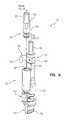
- FIG. 3is an exploded perspective view of the illustrative diverter assembly, including the diverter valve and connector of FIG. 1 ;
- FIG. 4is an exploded perspective view of the diverter valve and connector of FIG. 3 ;
- FIG. 5is a perspective view, in partial cross-section, of the diverter valve secured within the coupler
- FIG. 6is a perspective view, in partial cross-section, similar to FIG. 5 but with the diverter valve replaced with a sealing plug;
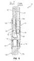
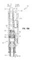
- FIG. 7is a cross-sectional view of the diverter valve secured within the connector
- FIG. 8Ais a detailed cross-sectional view of the diverter valve of FIG. 7 , with the valve member in a rest position;
- FIG. 8Bis a detailed cross-sectional view similar to FIG. 8A , with the valve member in a spout delivery position;
- FIG. 8Cis a detailed cross-sectional view similar to FIG. 8A , with the valve member in a sprayer delivery position;
- FIG. 9is a perspective view of the connector of FIG. 1 , showing the inlet tube removed from the inlet passage, the spout tube received within the first outlet passage, and the sealing plug received within the second outlet passage;
- FIG. 10is a perspective view similar to FIG. 9 , showing the inlet tube received within the inlet passage of the connector and secured through a retaining clip;
- FIG. 11is a cross-sectional view taken along line 11 - 11 of FIG. 10 ;
- FIG. 12is a perspective view similar to FIG. 9 , showing the sealing plug removed from the second outlet passage;
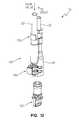
- FIG. 13is a perspective view similar to FIG. 12 , showing the diverter valve positioned for receipt within the second outlet passage of the connector;
- FIG. 14is a perspective view similar to FIG. 13 , showing the diverter valve received within the second outlet passage of the connector;
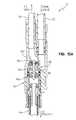
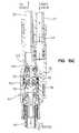
- FIG. 15Ais a cross-sectional view taken along line 15 - 15 of FIG. 14 , with the diverter secured within the connector and the valve member in the rest position of FIG. 8A ;
- FIG. 15Bis a cross-sectional view similar to FIG. 15A , with the valve member in the spout delivery position of FIG. 8B for permitting water flow from the inlet tube to the spout outlet tube;
- FIG. 15Cis a cross-sectional view similar to FIG. 15A , with the valve member in the sprayer delivery position of FIG. 8C for permitting water flow from the inlet tube to the sprayer outlet tube.
- a sink assembly 2is shown as including a sink or mounting deck 4 supporting an illustrative faucet assembly 10 above a sink basin 6 .
- the faucet assembly 10is shown as including the diverter assembly 12 of the present disclosure.
- the faucet assembly 10includes a waterway assembly 11 having a hot water supply line or tube 16 and a cold water supply line or tube 18 configured to supply water to a control or mixing valve 20 through a valve interface member 21 .
- the hot water supply tube 16is fluidly connected to a hot water supply valve or stop 17
- the cold water supply tube 18is fluidly connected to a cold water supply valve or stop 19 .
- Operation of the mixing valve 20regulates the flow of water from the hot water supply tube 16 and the cold water supply tube 18 to a mixed water line or inlet tube 22 .
- a user inputillustratively a handle 23 , is operably coupled to the mixing valve 20 to control the flow rate and the temperature of water delivered to the mixed water inlet tube 22 .
- the mixed water inlet tube 22includes an inlet end 24 and an outlet end 26 .
- the faucet assembly 10includes a delivery spout 28 supported by a base 29 and configured to receive a spout outlet tube 30 having an outlet 31 positioned above the sink basin 6 and configured to discharge water from the mixed water inlet tube 22 .
- the outlet 31may be defined by an aerator 33 coupled to an overmolded end fitting 35 of the spout outlet tube 30 .
- the base 29may be secured to the mounting deck 4 through nuts 32 threadably engaging mounting shanks or posts 34 .
- the hot water supply tube 16 , the cold water supply tube 18 , the mixed water inlet tube 22 , the spout outlet tube 30 , and the valve interface member 21are all formed of a polymer, such as a cross-liked polyethylene (PEX).
- PEXcross-liked polyethylene
- An auxiliary fluid dispenserillustratively a sprayer assembly 42 includes a handheld sprayer 44 fluidly coupled to a dispenser or sprayer outlet tube 46 .
- the sprayer 44may be of conventional design and includes a trigger 47 configured to activate water flow therethrough.
- the sprayer 44includes a body 48 configured to be removably supported by a mounting base 50 .
- the mounting base 50includes a mounting shank or post 52 defining a passageway 54 to slidably receive the sprayer outlet tube 46 .
- a nut 56threadably engages the mounting post 52 and secures the mounting base 50 to the mounting deck 4 . While the illustrative auxiliary fluid dispenser is shown as comprising sprayer assembly 42 , it should be noted that other fluid delivery devices may be substituted therefore, including a filtered water dispenser.
- the diverter assembly 12illustratively includes a coupler or connector 62 having a connector housing 64 secured to an inlet end 66 of the spout outlet tube 30 .
- the connector housing 64illustratively includes an inlet passage 68 coupled to the mixed water inlet tube 22 , a first outlet passage 70 coupled to a first water delivery device (illustratively the outlet 31 of the delivery spout 28 as shown in FIG. 5 ) through the spout outlet tube 30 , and a second outlet passage 72 configured to be coupled to a second water delivery device (illustratively the sprayer 44 ) through the sprayer outlet tube 46 .
- the longitudinal axis of the inlet end 66 of the spout outlet tube 30is coaxial with the longitudinal axis 71 of the first outlet passage 70 , which, in turn, is substantially parallel to the longitudinal axis 69 of the inlet passage 68 and the longitudinal axis 73 of the second outlet passage 72 ( FIG. 7 ).
- the connector housing 64is formed by a polyethylene overmolded around the inlet end 66 of the spout outlet tube 30 and subsequently cross-linked to cross-linked polyethylene (PEX).
- PEXpolyethylene
- the polyethylene of tube 30 and connector housing 64(which have not been cross-linked or have been only partially cross-linked) are cross-linked following the overmolding process. While it is envisioned that any form of suitable cross-linking may be utilized to form the PEX of tube 30 and connector housing 64 , in one illustrative embodiment the polyethylene is cross-linked by bombarding it with electromagnetic (gamma) or high energy electron (beta) radiation.
- the precise composition of the tube 30 and overmolded connector housing 64are not required to be of any specified polymer, in general, there are several guidelines which are applicable in the practice of the illustrative embodiment. It is of course, recognized that the precise operating conditions utilized in the overmolding process are well-known in the art and are specific to each molded polymer. It is well within the skill of the art to determine the applicable conditions which will result in the appropriate overmolded connector housing 64 and tube 30 .
- the tube 30 and connector housing 64may be a thermoplastic or a thermoset.
- the polymer overmolded connector housing 64should be capable of forming a leak-proof bond, either chemical or physical, with the polymer of the tube 30 .
- the combination of polymers of the tube 30 and the connector housing 64illustratively satisfy at least two simultaneous conditions.
- the tube 30illustratively does not soften and begin melt flow to the point where they lose structural integrity and
- the overmolded connector housing 64is illustratively capable of forming an essentially leak-proof interface with the plastic conduit, preferably through either a chemical and/or physical bond between the underlying plastic and the overmolded plastic.
- the tube 30is capable of maintaining structural integrity during the overmolding conditions during which the overmolded polymer is in melt flow.
- the composition of the overmolded connector housing 64will be such that it will be capable of at least some melt fusion with the composition of the tube 30 , thereby maximizing the leak-proof characteristics of the interface between the tube 30 and overmolded connector housing 64 .
- thismay be effected.
- One of the simplest proceduresis to insure that at least a component of the tube 30 and that of the overmold connector housing 64 is the same.
- a diverter valve 78is secured to the inlet end 80 of the sprayer tube 46 . More particularly, a diverter housing 82 is illustratively coaxially positioned relative to the sprayer tube 46 . A pair of spring biased tabs 84 secure the diverter housing 82 to an end fitting 86 which, in turn, is secured to the sprayer tube 46 by a metal ferrule 88 crimped or swaged in place. A valve member 90 is received within the diverter housing 82 and is configured to move relative thereto to control the flow of water from an inlet port 92 to first and second outlet ports 94 and 96 . An o-ring 97 forms a seal between the end fitting 86 and the diverter housing 82 .
- the valve member 90 of the diverter valve 78includes a poppet or stem 98 movably supported within a chamber 100 fluidly connecting the inlet port 92 to the outlet ports 94 and 96 .
- the stem 98supports a first seal 102 configured to seal against a first seat 104 defined by the diverter housing 82 and prevent fluid flow from the inlet port 92 to the first outlet port 94 .
- the stem 98also supports a second seal 106 , illustratively including a lip or skirt 108 , configured to seal against a second seat 110 defined by the diverter housing 82 and prevent fluid flow to the second outlet 96 .
- the valve member 90may operate in a known manner in response to differential water pressure changes wherein FIG. 8A shows the valve member 90 in a rest position, FIG. 8B shows the valve member 90 in a spout delivery position, and FIG. 8C shows the valve member 90 in a sprayer delivery position.
- the diverter valve 78is configured to be slidably received within the second outlet passage 72 of the connector housing 64 for use with a faucet assembly 10 including sprayer assembly 42 , thereby defining a multiple water outlet configuration.
- the diverter housing 82is dimensioned so as to slidably pass through the conventional mounting shank 52 configured to support the sprayer 44 .
- the diverter housing 82is asymmetric to facilitate passage through the mounting shank 52 and receipt within the second outlet passage 72 of the connector housing 64 . In the illustrative embodiment of FIG.
- the outer diameter (“od”) of the diverter housing 82is less than about 0.80 inches for slidably passing through the inner diameter (“id”) defining the passageway 54 of the deck mounting shank 52 .
- O-rings 111provide a seal between the diverter housing 82 and the connector housing 64 .
- a couplerillustratively a retaining clip 118 alternatively secures the diverter valve 78 and plug 112 within the connector housing 64 .
- the clip 118includes two pairs of biased arms 120 and 122 configured to pass through slots 124 and 126 in the connector housing 64 and to be alternately received within grooves 128 and 130 formed within the diverter housing 82 and the plug 112 , respectively.
- the clip 118also includes a handle 132 for manipulation by a user.
- the outlet end 26 of the mixed water inlet tube 22includes a fitting 134 , illustratively formed of a polyethylene overmolded on the outlet end 26 and subsequently cross-linked to form PEX.
- the fitting 134is configured to be received within the inlet passage 68 of the connector housing 64 .
- a retaining clipillustratively swing clip 136 , couples the fitting 134 to the connector housing 64 .
- the swing clip 136includes a first clip portion 138 retained within a groove 140 of the connector housing 64 , and a second clip portion 142 configured to cooperate with an edge 144 of the fitting 134 .
- the first clip portion 138is restrained from axial movement, but is free to rotate, such that the second clip portion 142 may be rotated into and out of engagement with the mixed water inlet tube 22 .
- FIGS. 9-11illustrate the diverter assembly 12 configured to operate as a non-sprayer faucet 10 and as it would leave the factory ready for installation.
- the path of water from the valve 20 to spout outlet tube 30can be clearly seen by arrows 146 in FIG. 11 .
- FIG. 12shows the retaining clip 118 for the plug 112 in the disengaged position and the plug 112 being removed. This step may be performed at installation, or during a subsequent retrofit, to add the sprayer assembly 42 including diverter valve 78 .
- FIG. 13shows the diverter valve 78 of the tube 46 being inserted into the connector housing 64 on the spout outlet tube 30 .
- the retaining clip 118 used to secure the plug 112is also used to secure in the diverter valve 78 .
- FIG. 14shows the completed diverter assembly 12 as it would appear after installation of the sprayer assembly 42 .
- FIG. 15Ashows a cross section of FIG. 14 when the valve member 90 is in the rest position of FIG. 8A (i.e. no water supplied from valve 20 to diverter valve 78 ).
- the water 146flows in from the valve 20 into the center portion of the diverter stem 98 and either exits out the spout outlet tube 30 ( FIG. 15B ) or out the sprayer tube 46 ( FIG. 15C ), depending on whether the sprayer trigger 47 has been actuated.
- water 146 supplied from the mixed water inlet tube 22enters the diverter valve 78 through inlet port 92 and is received within the chamber 100 intermediate the first and second seals 102 and 106 .
- the sprayer trigger 47when the sprayer trigger 47 is deactivated, there is no substantial pressure differential across the second seal 106 .
- the spout outlet tube 30is open to atmosphere thereby creating a pressure differential across the first seal 102 .
- the diverter valve 78is therefore in a first or delivery spout mode of operation, where stem 98 is moved upwardly in FIGS. 8B and 15B , away from the inlet port 92 .
- the first seal 102disengages the seat 104 and water flows through the spout outlet tube 30 .
- the present disclosureprovides a diverter valve and associated waterway that are configured to pass through a conventional opening in the sink deck.
- this diverter valvecould facilitate the use of tubular liners for a kitchen faucet where the spout is coaxial to the valve, thus allowing for the elimination of spout o-rings and potential for contact with the spout material, which may contain materials such as lead.
- This configurationwould also apply to other faucet configurations, including faucets where the valve and spout are located in separate mounting openings in the sink deck.
Landscapes
- Engineering & Computer Science (AREA)
- General Engineering & Computer Science (AREA)
- Health & Medical Sciences (AREA)
- Life Sciences & Earth Sciences (AREA)
- Hydrology & Water Resources (AREA)
- Public Health (AREA)
- Water Supply & Treatment (AREA)
- Mechanical Engineering (AREA)
- Domestic Plumbing Installations (AREA)
- Valve Housings (AREA)
Abstract
Description
Claims (10)
Priority Applications (1)
| Application Number | Priority Date | Filing Date | Title |
|---|---|---|---|
| US12/992,442US8646476B2 (en) | 2008-05-21 | 2009-05-21 | Integrated kitchen faucet side spray and diverter |
Applications Claiming Priority (3)
| Application Number | Priority Date | Filing Date | Title |
|---|---|---|---|
| US12846308P | 2008-05-21 | 2008-05-21 | |
| US12/992,442US8646476B2 (en) | 2008-05-21 | 2009-05-21 | Integrated kitchen faucet side spray and diverter |
| PCT/US2009/044850WO2009143352A1 (en) | 2008-05-21 | 2009-05-21 | Integrated kitchen faucet side spray and diverter |
Related Parent Applications (1)
| Application Number | Title | Priority Date | Filing Date |
|---|---|---|---|
| PCT/US2009/044850A-371-Of-InternationalWO2009143352A1 (en) | 2008-05-21 | 2009-05-21 | Integrated kitchen faucet side spray and diverter |
Related Child Applications (1)
| Application Number | Title | Priority Date | Filing Date |
|---|---|---|---|
| US14/147,412DivisionUS9243389B2 (en) | 2008-05-21 | 2014-01-03 | Integrated kitchen faucet side spray and diverter |
Publications (2)
| Publication Number | Publication Date |
|---|---|
| US20110061754A1 US20110061754A1 (en) | 2011-03-17 |
| US8646476B2true US8646476B2 (en) | 2014-02-11 |
Family
ID=41340555
Family Applications (2)
| Application Number | Title | Priority Date | Filing Date |
|---|---|---|---|
| US12/992,442Active2030-05-25US8646476B2 (en) | 2008-05-21 | 2009-05-21 | Integrated kitchen faucet side spray and diverter |
| US14/147,412Active2029-07-23US9243389B2 (en) | 2008-05-21 | 2014-01-03 | Integrated kitchen faucet side spray and diverter |
Family Applications After (1)
| Application Number | Title | Priority Date | Filing Date |
|---|---|---|---|
| US14/147,412Active2029-07-23US9243389B2 (en) | 2008-05-21 | 2014-01-03 | Integrated kitchen faucet side spray and diverter |
Country Status (4)
| Country | Link |
|---|---|
| US (2) | US8646476B2 (en) |
| CN (1) | CN102037268B (en) |
| CA (2) | CA2723111C (en) |
| WO (1) | WO2009143352A1 (en) |
Cited By (12)
| Publication number | Priority date | Publication date | Assignee | Title |
|---|---|---|---|---|
| US20140150896A1 (en)* | 2010-02-04 | 2014-06-05 | Globe Union Industrial Corp. | Assemblable faucet |
| US8789854B2 (en) | 2011-12-09 | 2014-07-29 | Mercury Plastics, Inc. | Quick-connect tube coupling |
| US9194110B2 (en) | 2012-03-07 | 2015-11-24 | Moen Incorporated | Electronic plumbing fixture fitting |
| US20180274214A1 (en)* | 2017-03-21 | 2018-09-27 | Delta Faucet Company | Hands-free sprayer |
| US10288316B1 (en) | 2013-07-29 | 2019-05-14 | Mercury Plastics Llc | Dip tube |
| US10364907B2 (en)* | 2017-05-09 | 2019-07-30 | Guangzhou Seagull Kitchen And Bath Products Co., Ltd. | Valve body structure facilitating maintenance of hose |
| US10633840B2 (en) | 2018-03-30 | 2020-04-28 | Fb Global Plumbing Group Llc | Faucet with hose connection |
| US10914056B2 (en) | 2018-09-14 | 2021-02-09 | Delta Faucet Company | Vessel rinsing apparatus |
| TWI808643B (en)* | 2021-09-25 | 2023-07-11 | 大陸商浙江盛美潔具有限公司 | Flow division water outlet device |
| US11898676B2 (en) | 2020-05-13 | 2024-02-13 | Mercury Plastics Llc | Quick-connect fitting |
| US12084261B1 (en) | 2019-05-13 | 2024-09-10 | Mercury Plastics Llc | Pipe nipple insert and dip tube |
| US12239278B2 (en) | 2019-08-19 | 2025-03-04 | Delta Faucet Company | Vessel rinsing apparatus, drain receptacle, interchangeable nozzle assembly, and faucet system including same |
Families Citing this family (13)
| Publication number | Priority date | Publication date | Assignee | Title |
|---|---|---|---|---|
| US20130019977A1 (en)* | 2011-07-22 | 2013-01-24 | Kent Plastic Co., Ltd. | Faucet assembly with insulating core |
| US9334634B2 (en) | 2013-03-15 | 2016-05-10 | Kohler Co. | Mixing valve assembly for faucet |
| DE102014109806B4 (en)* | 2014-07-13 | 2024-02-08 | Kludi Gmbh & Co. Kg | Water outlet fitting for a washbasin or sink |
| US10028625B2 (en)* | 2016-12-08 | 2018-07-24 | Marion J Tarlton | Over a sink retractable and extendable towel hanging apparatus |
| US11396740B2 (en)* | 2019-01-18 | 2022-07-26 | Kohler Co. | Independent control free standing bath filler |
| US11096550B1 (en) | 2019-02-04 | 2021-08-24 | Insinger Machine Co. | Semi-automatic ware washing sprayer system |
| US11555298B2 (en)* | 2020-01-17 | 2023-01-17 | Delta Faucet Company | Locking side sprayer |
| EP3872271B1 (en)* | 2020-02-27 | 2023-08-30 | Kludi GmbH & Co. KG | Water outlet fitting with extensible dish rinser |
| USD948665S1 (en)* | 2020-05-29 | 2022-04-12 | Delta Faucet Company | Sprayer |
| DE202020105935U1 (en)* | 2020-10-16 | 2022-01-18 | Neoperl Gmbh | Use of a hose for the fluidic connection of an outlet piece with a valve on a sanitary fitting, fluidic arrangement and corresponding sanitary fitting |
| CN114542765A (en)* | 2022-01-20 | 2022-05-27 | 厦门英仕卫浴有限公司 | Tap with intelligent control function |
| CN219472817U (en)* | 2023-02-14 | 2023-08-04 | 路达(厦门)工业有限公司 | a faucet |
| US20250251052A1 (en)* | 2024-02-02 | 2025-08-07 | Assa Abloy Americas Residential Inc. | Faucet including fluid junction assembly with flow limiter |
Citations (91)
| Publication number | Priority date | Publication date | Assignee | Title |
|---|---|---|---|---|
| US3336935A (en) | 1964-07-28 | 1967-08-22 | James Hamilton Bletcher | Diverter |
| US3459207A (en) | 1965-04-20 | 1969-08-05 | Kenneth G Bacheller | Faucet construction |
| US3520325A (en) | 1969-02-20 | 1970-07-14 | Harry A Stuart | Integrally cast conduit for a valve having a plastic body |
| US3600723A (en) | 1969-08-18 | 1971-08-24 | Stanadyne Inc | Faucet-mounting construction |
| US3620254A (en) | 1969-09-22 | 1971-11-16 | Standard Screw | Handle valve |
| US3757824A (en) | 1972-05-15 | 1973-09-11 | Ge Mo Co | Vacuum tube and connector assembly |
| US3796380A (en) | 1972-12-22 | 1974-03-12 | Sajar Plastics Inc | Molded plastic plumbing fixture |
| US3835887A (en) | 1971-07-29 | 1974-09-17 | Stanadyne Inc | Valve construction with water modulation |
| US3998240A (en) | 1975-06-13 | 1976-12-21 | Liautaud James P | Injection-molded faucet assembly |
| US4026328A (en) | 1975-07-28 | 1977-05-31 | Zin-Plas Corporation | Lavatory spout |
| US4076279A (en) | 1975-09-23 | 1978-02-28 | Hermann Hemscheidt Maschinenfabrik | Plug-in coupling |
| US4103709A (en) | 1976-09-13 | 1978-08-01 | Stanadyne, Inc. | Spout tube assembly |
| US4337795A (en) | 1975-04-28 | 1982-07-06 | Sterling Faucet Company | Single lever mixing faucet |
| US4356574A (en) | 1980-05-08 | 1982-11-02 | Jh Industries, Inc. | Faucet assembly with pinch valves |
| US4387738A (en) | 1981-03-30 | 1983-06-14 | Elkay Manufacturing Company | Spread center faucet |
| US4458839A (en) | 1982-03-03 | 1984-07-10 | Masco Corporation | Thermostatic valve assembly |
| US4513769A (en) | 1982-06-28 | 1985-04-30 | Masco Corporation Of Indiana | Method of manufacturing faucets and spouts, faucet inserts, and faucets and spouts manufactured by the method |
| US4552171A (en) | 1983-04-22 | 1985-11-12 | Elkay Manufacturing Company | Supply conduit mounting assembly for single lever faucet |
| US4577653A (en) | 1983-06-30 | 1986-03-25 | Masco Corporation | Anti-siphon and anti-knock diverter valve |
| US4607659A (en) | 1985-08-12 | 1986-08-26 | Cole George S | Valve with resilient tubes having constricted portions |
| US4609006A (en)* | 1984-11-29 | 1986-09-02 | American Standard Inc. | Diverter |
| US4610429A (en) | 1983-04-25 | 1986-09-09 | Sajar Plastics, Inc. | Plumbing connection |
| US4626005A (en) | 1983-07-06 | 1986-12-02 | Gustav Stifter | Fluid-tight flexible connection between hollow sections |
| US4635673A (en) | 1985-03-05 | 1987-01-13 | Wpm, Inc. | Accessory faucet |
| US4649958A (en) | 1982-06-28 | 1987-03-17 | Masco Corporation Of Indiana | Faucet and spout construction |
| US4754993A (en) | 1986-10-28 | 1988-07-05 | Handy & Harman Automotive Group, Inc. | Conduit harness connector assembly |
| US4760871A (en) | 1985-07-11 | 1988-08-02 | Fmc Corporation | Lower bead breaker removal and adjustment apparatus |
| US4762143A (en) | 1985-05-20 | 1988-08-09 | Botnick Irlin H | Faucet manifold |
| US4798221A (en) | 1987-07-27 | 1989-01-17 | Masco Corporation Of Indiana | Self sealing anti-knock diverter valve |
| WO1991005191A1 (en) | 1989-10-05 | 1991-04-18 | Masco Corporation | Cartridge for a single control lever mixing faucet with connecting pipes reinforced by elastic means |
| US5027851A (en) | 1990-07-17 | 1991-07-02 | Whirlpool Corporation | Spout assembly for hot water dispenser |
| US5073991A (en) | 1991-01-16 | 1991-12-24 | 501 Masco Industries, Inc. | Pull-out lavatory |
| US5090062A (en) | 1989-12-13 | 1992-02-25 | Kwc Ag | Sanitary fitting |
| US5095554A (en) | 1990-05-08 | 1992-03-17 | Kwc Ag | Sanitary fitting |
| US5100565A (en) | 1990-06-29 | 1992-03-31 | Tokyo Yogyo Kabushiki Kaisha | Valve of faucet |
| US5131428A (en) | 1991-03-01 | 1992-07-21 | Injecto Mold, Inc. | Faucet with unitary underbody |
| US5219185A (en) | 1990-11-13 | 1993-06-15 | Itw Fastex Italia S.P.A. | Snap-on fluidtight pipe connecting device |
| EP0632220A2 (en) | 1993-06-30 | 1995-01-04 | Solid Plast S.R.L. | Composite body for taps |
| US5494259A (en) | 1994-12-30 | 1996-02-27 | Moen Incorporated | Reinforced non-metallic faucet body |
| US5558128A (en) | 1994-05-05 | 1996-09-24 | Friedrich Grohe Aktiengesellschaft | One-hole mount mixing faucet |
| US5566707A (en) | 1995-09-28 | 1996-10-22 | Emhart Inc. | Putty plate |
| US5573037A (en) | 1995-11-27 | 1996-11-12 | George S. Cole & Associates, Incorporated | Faucet valve with external cam and pinch tubes |
| US5642755A (en) | 1995-09-28 | 1997-07-01 | Emhart Inc. | Faucet |
| US5653868A (en) | 1994-04-06 | 1997-08-05 | Mitsubishi Rayon Company Ltd. | Diverter and water purifier having same |
| US5669417A (en) | 1996-08-30 | 1997-09-23 | Lian-Jie; Kuo | Water-guide device in a tap |
| US5685341A (en) | 1996-09-10 | 1997-11-11 | Amerikam, Inc. | Water faucet with quick-connect socket |
| US5687952A (en) | 1995-10-11 | 1997-11-18 | Wave Corporation | Water faucet poppet valve |
| EP0808952A1 (en) | 1996-05-23 | 1997-11-26 | REAL S.r.l. | Device for coupling faucet assemblies to sanitary articles such as wash-basins, lavabos, bidets, bath-tubs and the like |
| US5701926A (en) | 1995-06-07 | 1997-12-30 | The Rubinet Faucet Company | Backflow prevention device and vacuum breaker for kitchen plumbing |
| US5725008A (en) | 1996-06-03 | 1998-03-10 | Johnson; Floyd M. | Reinforcing member attached to a sink at a place of installation of a faucet set |
| US5746244A (en) | 1997-02-06 | 1998-05-05 | Emhart Inc. | Unitary throat plate/putty plate for a faucet |
| US5803120A (en) | 1995-01-24 | 1998-09-08 | American Standard Inc. | Faucets for sanitary fixtures with interchangeable decorative elements |
| US5865473A (en) | 1997-01-21 | 1999-02-02 | Emhart Inc. | Isolated conduit system |
| US5871029A (en) | 1996-02-28 | 1999-02-16 | Peteri; Henri Bernard | Hot water tap |
| US5881754A (en) | 1997-08-18 | 1999-03-16 | Wei; Ming Te | Valve device for faucet and spray gun |
| US5884662A (en) | 1998-07-28 | 1999-03-23 | Chung Cheng Faucet Co., Ltd. | Protective guide sleeve structure of a pulling type faucet |
| US5937892A (en) | 1993-04-08 | 1999-08-17 | Ideal-Standard Gmbh | Sanitary water valve |
| US5944225A (en) | 1997-09-04 | 1999-08-31 | The Meyer Company | Insulated faucet for dispensing hot liquids |
| US5950663A (en) | 1998-03-05 | 1999-09-14 | Bloomfield; Terence M. | Faucet installation system |
| US5960490A (en) | 1998-04-16 | 1999-10-05 | American Standard Inc. | Single handle faucet fixture |
| US5979489A (en) | 1998-04-16 | 1999-11-09 | American Standard Inc. | Single and dual handle fittings with interchangeable components |
| US6023796A (en) | 1998-04-16 | 2000-02-15 | American Standard Inc. | Putty plate for faucet fixture |
| US6062251A (en) | 1998-04-16 | 2000-05-16 | American Standard Inc. | Water valve for faucet fitting |
| US6070614A (en) | 1999-03-08 | 2000-06-06 | Moen Incorporated | Faucet mounting system with improved bearing support |
| US6073972A (en) | 1998-05-19 | 2000-06-13 | Emhart Inc. | Composite body faucet connection |
| US6079447A (en) | 1999-03-08 | 2000-06-27 | Moen Incorporated | Faucet mounting system with improved stand |
| US6085784A (en) | 1998-08-13 | 2000-07-11 | Emhart Inc. | Quick connect hose assembly |
| US6123106A (en) | 1999-12-03 | 2000-09-26 | Emhart Inc. | Thrust washer |
| US6138296A (en) | 1999-06-23 | 2000-10-31 | Emhart Inc. | Easy connect and disconnect faucet spout assembly |
| US6202686B1 (en) | 1999-01-29 | 2001-03-20 | American Standard Inc. | Faucet with one-piece manifold |
| US6256810B1 (en) | 2000-06-16 | 2001-07-10 | Emhart Inc. | Easy connect and disconnect faucet spout assembly |
| US6305407B1 (en) | 1998-12-04 | 2001-10-23 | Samar, Inc. | Safety hose system |
| US6328059B1 (en) | 2000-03-22 | 2001-12-11 | Alessandro Testori | Top mounted faucet assembly |
| WO2002025022A1 (en) | 2000-09-22 | 2002-03-28 | Newfrey, Llc | Faucet with underbody |
| US20020167171A1 (en) | 1997-12-09 | 2002-11-14 | Ulrich Becker | Sanitary Fitting |
| DE10133041A1 (en) | 2001-07-11 | 2003-01-30 | Grohe Armaturen Friedrich | Mixer tap is fitted with valve cartridge which fits into housing mounted under plaster connecting hot and cold water feeds with bath outlet and shower outlet |
| US20030102256A1 (en) | 2000-08-08 | 2003-06-05 | Toshio Takagi | Combination tap with external water purifier |
| US6609732B1 (en) | 2002-02-01 | 2003-08-26 | General Motors Corporation | Quick connect multi-hose connector |
| US20040011399A1 (en) | 2002-07-17 | 2004-01-22 | Segien Donald J. | Side control faucet with diverter assembly |
| US6729344B1 (en) | 2002-10-23 | 2004-05-04 | Shion Choin Industrial Co., Ltd. | Faucet for a cold/hot fountain water machine |
| US20040117906A1 (en) | 2001-09-21 | 2004-06-24 | Baker Scott C. | Faucet with underbody |
| US6757921B2 (en) | 2002-07-16 | 2004-07-06 | Kohler Co. | Pull-out faucet |
| US6920892B2 (en) | 2003-09-24 | 2005-07-26 | Neoperl, Inc. | Side spray diverter valve |
| US7000854B2 (en) | 2002-11-08 | 2006-02-21 | Moen Incorporated | Pullout spray head with single-button mode selector |
| US20060117477A1 (en) | 2004-12-03 | 2006-06-08 | Rosko M S | Sprayer with non-faucet control |
| US20060131228A1 (en) | 2003-07-08 | 2006-06-22 | David Truong | Filtration assembly for mixing faucet |
| US7096879B2 (en) | 2002-10-22 | 2006-08-29 | Avilion Limited | Pillar sink mixer with hand spray |
| CN2823722Y (en) | 2005-08-31 | 2006-10-04 | 深圳成霖洁具股份有限公司 | Water tap controller |
| US7121303B1 (en) | 2004-08-02 | 2006-10-17 | Ren-Yih Hwang | Mixed water faucet |
| US7216663B2 (en)* | 2004-10-05 | 2007-05-15 | Brasstech Inc. | Diverting device for bridge faucet with hand spray |
| US20080178935A1 (en) | 2007-01-31 | 2008-07-31 | Masco Corporation Of Indiana | Diverter integrated into a side sprayer |
Family Cites Families (1)
| Publication number | Priority date | Publication date | Assignee | Title |
|---|---|---|---|---|
| US7212303B2 (en)* | 2001-08-03 | 2007-05-01 | Canon Kabushiki Kaisha | Print control method for a multifunctional printer including a facsimile feature |
- 2009
- 2009-05-21CNCN200980118915.XApatent/CN102037268B/enactiveActive
- 2009-05-21USUS12/992,442patent/US8646476B2/enactiveActive
- 2009-05-21CACA2723111Apatent/CA2723111C/enactiveActive
- 2009-05-21CACA2859105Apatent/CA2859105C/enactiveActive
- 2009-05-21WOPCT/US2009/044850patent/WO2009143352A1/enactiveApplication Filing
- 2014
- 2014-01-03USUS14/147,412patent/US9243389B2/enactiveActive
Patent Citations (93)
| Publication number | Priority date | Publication date | Assignee | Title |
|---|---|---|---|---|
| US3336935A (en) | 1964-07-28 | 1967-08-22 | James Hamilton Bletcher | Diverter |
| US3459207A (en) | 1965-04-20 | 1969-08-05 | Kenneth G Bacheller | Faucet construction |
| US3520325A (en) | 1969-02-20 | 1970-07-14 | Harry A Stuart | Integrally cast conduit for a valve having a plastic body |
| US3600723A (en) | 1969-08-18 | 1971-08-24 | Stanadyne Inc | Faucet-mounting construction |
| US3620254A (en) | 1969-09-22 | 1971-11-16 | Standard Screw | Handle valve |
| US3835887A (en) | 1971-07-29 | 1974-09-17 | Stanadyne Inc | Valve construction with water modulation |
| US3757824A (en) | 1972-05-15 | 1973-09-11 | Ge Mo Co | Vacuum tube and connector assembly |
| US3796380A (en) | 1972-12-22 | 1974-03-12 | Sajar Plastics Inc | Molded plastic plumbing fixture |
| US4337795A (en) | 1975-04-28 | 1982-07-06 | Sterling Faucet Company | Single lever mixing faucet |
| US3998240A (en) | 1975-06-13 | 1976-12-21 | Liautaud James P | Injection-molded faucet assembly |
| US4026328A (en) | 1975-07-28 | 1977-05-31 | Zin-Plas Corporation | Lavatory spout |
| US4076279A (en) | 1975-09-23 | 1978-02-28 | Hermann Hemscheidt Maschinenfabrik | Plug-in coupling |
| US4103709A (en) | 1976-09-13 | 1978-08-01 | Stanadyne, Inc. | Spout tube assembly |
| US4356574A (en) | 1980-05-08 | 1982-11-02 | Jh Industries, Inc. | Faucet assembly with pinch valves |
| US4387738A (en) | 1981-03-30 | 1983-06-14 | Elkay Manufacturing Company | Spread center faucet |
| US4458839A (en) | 1982-03-03 | 1984-07-10 | Masco Corporation | Thermostatic valve assembly |
| US4649958A (en) | 1982-06-28 | 1987-03-17 | Masco Corporation Of Indiana | Faucet and spout construction |
| US4513769A (en) | 1982-06-28 | 1985-04-30 | Masco Corporation Of Indiana | Method of manufacturing faucets and spouts, faucet inserts, and faucets and spouts manufactured by the method |
| US4552171A (en) | 1983-04-22 | 1985-11-12 | Elkay Manufacturing Company | Supply conduit mounting assembly for single lever faucet |
| US4610429A (en) | 1983-04-25 | 1986-09-09 | Sajar Plastics, Inc. | Plumbing connection |
| US4577653A (en) | 1983-06-30 | 1986-03-25 | Masco Corporation | Anti-siphon and anti-knock diverter valve |
| US4626005A (en) | 1983-07-06 | 1986-12-02 | Gustav Stifter | Fluid-tight flexible connection between hollow sections |
| US4609006A (en)* | 1984-11-29 | 1986-09-02 | American Standard Inc. | Diverter |
| US4635673A (en) | 1985-03-05 | 1987-01-13 | Wpm, Inc. | Accessory faucet |
| US4762143A (en) | 1985-05-20 | 1988-08-09 | Botnick Irlin H | Faucet manifold |
| US4760871A (en) | 1985-07-11 | 1988-08-02 | Fmc Corporation | Lower bead breaker removal and adjustment apparatus |
| US4607659A (en) | 1985-08-12 | 1986-08-26 | Cole George S | Valve with resilient tubes having constricted portions |
| US4754993A (en) | 1986-10-28 | 1988-07-05 | Handy & Harman Automotive Group, Inc. | Conduit harness connector assembly |
| US4798221A (en) | 1987-07-27 | 1989-01-17 | Masco Corporation Of Indiana | Self sealing anti-knock diverter valve |
| WO1991005191A1 (en) | 1989-10-05 | 1991-04-18 | Masco Corporation | Cartridge for a single control lever mixing faucet with connecting pipes reinforced by elastic means |
| US5090062A (en) | 1989-12-13 | 1992-02-25 | Kwc Ag | Sanitary fitting |
| US5095554A (en) | 1990-05-08 | 1992-03-17 | Kwc Ag | Sanitary fitting |
| US5100565A (en) | 1990-06-29 | 1992-03-31 | Tokyo Yogyo Kabushiki Kaisha | Valve of faucet |
| US5027851A (en) | 1990-07-17 | 1991-07-02 | Whirlpool Corporation | Spout assembly for hot water dispenser |
| US5219185A (en) | 1990-11-13 | 1993-06-15 | Itw Fastex Italia S.P.A. | Snap-on fluidtight pipe connecting device |
| US5073991A (en) | 1991-01-16 | 1991-12-24 | 501 Masco Industries, Inc. | Pull-out lavatory |
| US5131428A (en) | 1991-03-01 | 1992-07-21 | Injecto Mold, Inc. | Faucet with unitary underbody |
| US5937892A (en) | 1993-04-08 | 1999-08-17 | Ideal-Standard Gmbh | Sanitary water valve |
| EP0632220A2 (en) | 1993-06-30 | 1995-01-04 | Solid Plast S.R.L. | Composite body for taps |
| US5653868A (en) | 1994-04-06 | 1997-08-05 | Mitsubishi Rayon Company Ltd. | Diverter and water purifier having same |
| US5558128A (en) | 1994-05-05 | 1996-09-24 | Friedrich Grohe Aktiengesellschaft | One-hole mount mixing faucet |
| US5494259A (en) | 1994-12-30 | 1996-02-27 | Moen Incorporated | Reinforced non-metallic faucet body |
| US5803120A (en) | 1995-01-24 | 1998-09-08 | American Standard Inc. | Faucets for sanitary fixtures with interchangeable decorative elements |
| US5701926A (en) | 1995-06-07 | 1997-12-30 | The Rubinet Faucet Company | Backflow prevention device and vacuum breaker for kitchen plumbing |
| US5566707A (en) | 1995-09-28 | 1996-10-22 | Emhart Inc. | Putty plate |
| US5642755A (en) | 1995-09-28 | 1997-07-01 | Emhart Inc. | Faucet |
| US5687952A (en) | 1995-10-11 | 1997-11-18 | Wave Corporation | Water faucet poppet valve |
| US5573037A (en) | 1995-11-27 | 1996-11-12 | George S. Cole & Associates, Incorporated | Faucet valve with external cam and pinch tubes |
| US5871029A (en) | 1996-02-28 | 1999-02-16 | Peteri; Henri Bernard | Hot water tap |
| EP0808952A1 (en) | 1996-05-23 | 1997-11-26 | REAL S.r.l. | Device for coupling faucet assemblies to sanitary articles such as wash-basins, lavabos, bidets, bath-tubs and the like |
| US5725008A (en) | 1996-06-03 | 1998-03-10 | Johnson; Floyd M. | Reinforcing member attached to a sink at a place of installation of a faucet set |
| US5669417A (en) | 1996-08-30 | 1997-09-23 | Lian-Jie; Kuo | Water-guide device in a tap |
| US5685341A (en) | 1996-09-10 | 1997-11-11 | Amerikam, Inc. | Water faucet with quick-connect socket |
| US5865473A (en) | 1997-01-21 | 1999-02-02 | Emhart Inc. | Isolated conduit system |
| US5746244A (en) | 1997-02-06 | 1998-05-05 | Emhart Inc. | Unitary throat plate/putty plate for a faucet |
| US5881754A (en) | 1997-08-18 | 1999-03-16 | Wei; Ming Te | Valve device for faucet and spray gun |
| US5944225A (en) | 1997-09-04 | 1999-08-31 | The Meyer Company | Insulated faucet for dispensing hot liquids |
| US20020167171A1 (en) | 1997-12-09 | 2002-11-14 | Ulrich Becker | Sanitary Fitting |
| US5950663A (en) | 1998-03-05 | 1999-09-14 | Bloomfield; Terence M. | Faucet installation system |
| US5960490A (en) | 1998-04-16 | 1999-10-05 | American Standard Inc. | Single handle faucet fixture |
| US5979489A (en) | 1998-04-16 | 1999-11-09 | American Standard Inc. | Single and dual handle fittings with interchangeable components |
| US6023796A (en) | 1998-04-16 | 2000-02-15 | American Standard Inc. | Putty plate for faucet fixture |
| US6062251A (en) | 1998-04-16 | 2000-05-16 | American Standard Inc. | Water valve for faucet fitting |
| US6073972A (en) | 1998-05-19 | 2000-06-13 | Emhart Inc. | Composite body faucet connection |
| US5884662A (en) | 1998-07-28 | 1999-03-23 | Chung Cheng Faucet Co., Ltd. | Protective guide sleeve structure of a pulling type faucet |
| US6085784A (en) | 1998-08-13 | 2000-07-11 | Emhart Inc. | Quick connect hose assembly |
| US6305407B1 (en) | 1998-12-04 | 2001-10-23 | Samar, Inc. | Safety hose system |
| US6202686B1 (en) | 1999-01-29 | 2001-03-20 | American Standard Inc. | Faucet with one-piece manifold |
| US6079447A (en) | 1999-03-08 | 2000-06-27 | Moen Incorporated | Faucet mounting system with improved stand |
| US6070614A (en) | 1999-03-08 | 2000-06-06 | Moen Incorporated | Faucet mounting system with improved bearing support |
| US6138296A (en) | 1999-06-23 | 2000-10-31 | Emhart Inc. | Easy connect and disconnect faucet spout assembly |
| US6123106A (en) | 1999-12-03 | 2000-09-26 | Emhart Inc. | Thrust washer |
| US6328059B1 (en) | 2000-03-22 | 2001-12-11 | Alessandro Testori | Top mounted faucet assembly |
| US6256810B1 (en) | 2000-06-16 | 2001-07-10 | Emhart Inc. | Easy connect and disconnect faucet spout assembly |
| US20030102256A1 (en) | 2000-08-08 | 2003-06-05 | Toshio Takagi | Combination tap with external water purifier |
| WO2002025022A1 (en) | 2000-09-22 | 2002-03-28 | Newfrey, Llc | Faucet with underbody |
| DE10133041A1 (en) | 2001-07-11 | 2003-01-30 | Grohe Armaturen Friedrich | Mixer tap is fitted with valve cartridge which fits into housing mounted under plaster connecting hot and cold water feeds with bath outlet and shower outlet |
| US20040117906A1 (en) | 2001-09-21 | 2004-06-24 | Baker Scott C. | Faucet with underbody |
| US6609732B1 (en) | 2002-02-01 | 2003-08-26 | General Motors Corporation | Quick connect multi-hose connector |
| US6757921B2 (en) | 2002-07-16 | 2004-07-06 | Kohler Co. | Pull-out faucet |
| US7077153B2 (en)* | 2002-07-17 | 2006-07-18 | Newfrey Llc | Side control faucet with diverter assembly |
| US20040011399A1 (en) | 2002-07-17 | 2004-01-22 | Segien Donald J. | Side control faucet with diverter assembly |
| US7096879B2 (en) | 2002-10-22 | 2006-08-29 | Avilion Limited | Pillar sink mixer with hand spray |
| US6729344B1 (en) | 2002-10-23 | 2004-05-04 | Shion Choin Industrial Co., Ltd. | Faucet for a cold/hot fountain water machine |
| US7000854B2 (en) | 2002-11-08 | 2006-02-21 | Moen Incorporated | Pullout spray head with single-button mode selector |
| US20060131228A1 (en) | 2003-07-08 | 2006-06-22 | David Truong | Filtration assembly for mixing faucet |
| US6920892B2 (en) | 2003-09-24 | 2005-07-26 | Neoperl, Inc. | Side spray diverter valve |
| US7121303B1 (en) | 2004-08-02 | 2006-10-17 | Ren-Yih Hwang | Mixed water faucet |
| US7216663B2 (en)* | 2004-10-05 | 2007-05-15 | Brasstech Inc. | Diverting device for bridge faucet with hand spray |
| US20060117477A1 (en) | 2004-12-03 | 2006-06-08 | Rosko M S | Sprayer with non-faucet control |
| CN2823722Y (en) | 2005-08-31 | 2006-10-04 | 深圳成霖洁具股份有限公司 | Water tap controller |
| US20080178935A1 (en) | 2007-01-31 | 2008-07-31 | Masco Corporation Of Indiana | Diverter integrated into a side sprayer |
| US7721761B2 (en)* | 2007-01-31 | 2010-05-25 | Masco Corporation Of Indiana | Diverter integrated into a side sprayer |
Non-Patent Citations (7)
| Title |
|---|
| International Search Report and Written Opinion for PCT Application No. PCT/US2009/044850, issued Jul. 14, 2009, 11 pgs. |
| Price Pfister 526 Series Hanover(TM) Collection Pull-Out Kitchen Faucet Parts Explosion, Sep. 15, 2006, 1 pg. |
| Price Pfister 526 Series Hanover(TM) Collection Pull-Out Kitchen Faucet Specification Submittal, Sep. 19, 2006, 1 pg. |
| Price Pfister 526 Series Hanover™ Collection Pull-Out Kitchen Faucet Parts Explosion, Sep. 15, 2006, 1 pg. |
| Price Pfister 526 Series Hanover™ Collection Pull-Out Kitchen Faucet Specification Submittal, Sep. 19, 2006, 1 pg. |
| Price Pfister Kitchen Hanover(TM) Collection options, 1 pg., at least as early as Nov. 12, 2010. |
| Price Pfister Kitchen Hanover™ Collection options, 1 pg., at least as early as Nov. 12, 2010. |
Cited By (21)
| Publication number | Priority date | Publication date | Assignee | Title |
|---|---|---|---|---|
| US20140150896A1 (en)* | 2010-02-04 | 2014-06-05 | Globe Union Industrial Corp. | Assemblable faucet |
| US8789854B2 (en) | 2011-12-09 | 2014-07-29 | Mercury Plastics, Inc. | Quick-connect tube coupling |
| US9103478B2 (en) | 2011-12-09 | 2015-08-11 | Mercury Plastics, Inc. | Quick-connect tube coupling |
| US10082232B2 (en) | 2011-12-09 | 2018-09-25 | Mercury Plastics Llc | Quick-connect tube coupling |
| US9194110B2 (en) | 2012-03-07 | 2015-11-24 | Moen Incorporated | Electronic plumbing fixture fitting |
| US9758951B2 (en) | 2012-03-07 | 2017-09-12 | Moen Incorporated | Electronic plumbing fixture fitting |
| US9828751B2 (en) | 2012-03-07 | 2017-11-28 | Moen Incorporated | Electronic plumbing fixture fitting |
| US10288316B1 (en) | 2013-07-29 | 2019-05-14 | Mercury Plastics Llc | Dip tube |
| US20180274214A1 (en)* | 2017-03-21 | 2018-09-27 | Delta Faucet Company | Hands-free sprayer |
| US10364907B2 (en)* | 2017-05-09 | 2019-07-30 | Guangzhou Seagull Kitchen And Bath Products Co., Ltd. | Valve body structure facilitating maintenance of hose |
| US10633840B2 (en) | 2018-03-30 | 2020-04-28 | Fb Global Plumbing Group Llc | Faucet with hose connection |
| US10914056B2 (en) | 2018-09-14 | 2021-02-09 | Delta Faucet Company | Vessel rinsing apparatus |
| US11473277B2 (en) | 2018-09-14 | 2022-10-18 | Delta Faucet Company | Vessel rinsing apparatus |
| US11725369B2 (en) | 2018-09-14 | 2023-08-15 | Delta Faucet Company | Vessel rinsing apparatus |
| US12006670B2 (en) | 2018-09-14 | 2024-06-11 | Delta Faucet Company | Vessel rinsing apparatus |
| US12084261B1 (en) | 2019-05-13 | 2024-09-10 | Mercury Plastics Llc | Pipe nipple insert and dip tube |
| US12239278B2 (en) | 2019-08-19 | 2025-03-04 | Delta Faucet Company | Vessel rinsing apparatus, drain receptacle, interchangeable nozzle assembly, and faucet system including same |
| US11898676B2 (en) | 2020-05-13 | 2024-02-13 | Mercury Plastics Llc | Quick-connect fitting |
| US12276364B2 (en) | 2020-05-13 | 2025-04-15 | Mercury Plastics Llc | Quick-connect fitting |
| TWI808643B (en)* | 2021-09-25 | 2023-07-11 | 大陸商浙江盛美潔具有限公司 | Flow division water outlet device |
| US12276342B1 (en) | 2021-09-25 | 2025-04-15 | Zhejiang Sunmixer Sanitary Ware Co., Ltd. | Flow division water outlet device |
Also Published As
| Publication number | Publication date |
|---|---|
| CN102037268A (en) | 2011-04-27 |
| US20140116529A1 (en) | 2014-05-01 |
| CA2723111A1 (en) | 2009-11-26 |
| CN102037268B (en) | 2015-09-02 |
| US20110061754A1 (en) | 2011-03-17 |
| CA2859105A1 (en) | 2009-11-26 |
| US9243389B2 (en) | 2016-01-26 |
| WO2009143352A1 (en) | 2009-11-26 |
| CA2723111C (en) | 2014-10-21 |
| CA2859105C (en) | 2018-11-27 |
Similar Documents
| Publication | Publication Date | Title |
|---|---|---|
| US8646476B2 (en) | Integrated kitchen faucet side spray and diverter | |
| EP2024672B1 (en) | Faucet including a molded waterway assembly | |
| CN102333965B (en) | faucet manifold | |
| CA2675296C (en) | Diverter integrated into a side sprayer | |
| US8870095B2 (en) | Locking pressurized fluid connection | |
| US8991425B2 (en) | Waterway assembly including an overmolded support plate | |
| EP2896759B1 (en) | Water dispensing device with spray head, particularly for sinks or similar hygienic-sanitary fixtures, with improved manoeuverability | |
| US8826932B2 (en) | Diverter valve | |
| US7293584B1 (en) | Faucet spout and diverter valve | |
| JP2009532631A (en) | Induction valve | |
| CA2845213C (en) | Faucet including a molded waterway assembly | |
| US20070080242A1 (en) | Faucet side spray with metal plated exterior and interior structures, and with inert internal waterway | |
| EP3382110B1 (en) | Tap and system for selectively delivering processed and unprocessed liquid | |
| CA2681259C (en) | Valve mounting assembly |
Legal Events
| Date | Code | Title | Description |
|---|---|---|---|
| AS | Assignment | Owner name:MASCO CORPORATION OF INDIANA, INDIANA Free format text:ASSIGNMENT OF ASSIGNORS INTEREST;ASSIGNORS:THOMAS, KURT J.;BROWN, DEREK A.;SIGNING DATES FROM 20080701 TO 20080710;REEL/FRAME:026013/0300 Owner name:MERCURY PLASTICS, INC., OHIO Free format text:CONFIRMATORY ASSIGNMENT;ASSIGNOR:MASCO CORPORATION OF INDIANA D/B/A DELTA FAUCET COMPANY;REEL/FRAME:026010/0189 Effective date:20100401 | |
| STCF | Information on status: patent grant | Free format text:PATENTED CASE | |
| AS | Assignment | Owner name:DELTA FAUCET COMPANY, INDIANA Free format text:ASSIGNMENT OF ASSIGNORS INTEREST;ASSIGNOR:MASCO CORPORATION OF INDIANA;REEL/FRAME:035168/0845 Effective date:20150219 | |
| FPAY | Fee payment | Year of fee payment:4 | |
| AS | Assignment | Owner name:GOLDEN EAGLE ACQUISITION LLC, MICHIGAN Free format text:ASSIGNMENT OF ASSIGNORS INTEREST;ASSIGNORS:MERCURY PLASTICS, INC.;NEO BEAM ALLIANCE, LIMITED;WILLIAM ROWLEY;REEL/FRAME:044895/0682 Effective date:20171201 | |
| AS | Assignment | Owner name:MERCURY PLASTICS LLC, OHIO Free format text:CHANGE OF NAME;ASSIGNOR:GOLDEN EAGLE ACQUISITION LLC;REEL/FRAME:045001/0256 Effective date:20171201 | |
| MAFP | Maintenance fee payment | Free format text:PAYMENT OF MAINTENANCE FEE, 8TH YEAR, LARGE ENTITY (ORIGINAL EVENT CODE: M1552); ENTITY STATUS OF PATENT OWNER: LARGE ENTITY Year of fee payment:8 | |
| MAFP | Maintenance fee payment | Free format text:PAYMENT OF MAINTENANCE FEE, 12TH YEAR, LARGE ENTITY (ORIGINAL EVENT CODE: M1553); ENTITY STATUS OF PATENT OWNER: LARGE ENTITY Year of fee payment:12 |