US8646131B2 - Variable height siderail - Google Patents
Variable height siderailDownload PDFInfo
- Publication number
- US8646131B2 US8646131B2US13/733,980US201313733980AUS8646131B2US 8646131 B2US8646131 B2US 8646131B2US 201313733980 AUS201313733980 AUS 201313733980AUS 8646131 B2US8646131 B2US 8646131B2
- Authority
- US
- United States
- Prior art keywords
- siderail
- rail
- outer link
- longitudinally
- segment
- Prior art date
- Legal status (The legal status is an assumption and is not a legal conclusion. Google has not performed a legal analysis and makes no representation as to the accuracy of the status listed.)
- Active
Links
Images


Classifications
- A—HUMAN NECESSITIES
- A47—FURNITURE; DOMESTIC ARTICLES OR APPLIANCES; COFFEE MILLS; SPICE MILLS; SUCTION CLEANERS IN GENERAL
- A47C—CHAIRS; SOFAS; BEDS
- A47C21/00—Attachments for beds, e.g. sheet holders or bed-cover holders; Ventilating, cooling or heating means in connection with bedsteads or mattresses
- A47C21/08—Devices for prevention against falling-out, e.g. detachable side walls
- A—HUMAN NECESSITIES
- A61—MEDICAL OR VETERINARY SCIENCE; HYGIENE
- A61G—TRANSPORT, PERSONAL CONVEYANCES, OR ACCOMMODATION SPECIALLY ADAPTED FOR PATIENTS OR DISABLED PERSONS; OPERATING TABLES OR CHAIRS; CHAIRS FOR DENTISTRY; FUNERAL DEVICES
- A61G7/00—Beds specially adapted for nursing; Devices for lifting patients or disabled persons
- A61G7/05—Parts, details or accessories of beds
- A61G7/0507—Side-rails
- A61G7/0508—Side-rails characterised by a particular connection mechanism
- A61G7/0509—Side-rails characterised by a particular connection mechanism sliding or pivoting downwards
- A—HUMAN NECESSITIES
- A61—MEDICAL OR VETERINARY SCIENCE; HYGIENE
- A61G—TRANSPORT, PERSONAL CONVEYANCES, OR ACCOMMODATION SPECIALLY ADAPTED FOR PATIENTS OR DISABLED PERSONS; OPERATING TABLES OR CHAIRS; CHAIRS FOR DENTISTRY; FUNERAL DEVICES
- A61G7/00—Beds specially adapted for nursing; Devices for lifting patients or disabled persons
- A61G7/05—Parts, details or accessories of beds
- A61G7/0507—Side-rails
- A61G7/0512—Side-rails characterised by customised length
- A61G7/0513—Side-rails characterised by customised length covering particular sections of the bed, e.g. one or more partial side-rail sections along the bed
- A61G7/0514—Side-rails characterised by customised length covering particular sections of the bed, e.g. one or more partial side-rail sections along the bed mounted to individual mattress supporting frame sections
Definitions
- Beds of the type used in hospitals, other health care facilities and home health care settingsinclude a frame, a deck, a mattress resting on the deck and a set of siderails.
- the siderailshave a deployed or raised position and a lowered or stored position. In the deployed position the top of the siderail should be a minimum distance above the top of the deck, and the bottom of the siderail should be low enough, and close enough to the neighboring lateral side of the deck, to ensure that any gap between the siderail and the deck is less than a specified amount, for example 60 mm.
- the top of the siderailIn the stowed position, the top of the siderail should be a minimum distance below the top of the mattress to facilitate occupant ingress and egress, and the distance from the bottom of the siderail to the floor should be no less than a prescribed amount, for example 120 mm.
- a siderail tall enough to satisfy the requirements of the deployed statemay be too tall to satisfy one or both of the requirements of the stored state.
- a siderail short enough to satisfy the requirements of the stored statemay be too short to satisfy one or both of the requirements of the deployed state.
- FIG. 1is a right side elevation view of a hospital bed having variable height siderails as described herein.
- FIG. 4is a view similar to that of FIG. 3 with the siderail in a lowered or stored state.
- FIGS. 7-10are a sequence of perspective views of the siderail of FIG. 5 as seen from the occupant side of the siderail showing the siderail in a deployed position, a partially lowered position, a more lowered position, and a stored position respectively.
- FIG. 11is a view similar to that of FIG. 3 showing a variable height siderail in which an outer link portion thereof is constructed of two pieces, the siderail being shown in a deployed position.
- FIG. 13is a view similar to that of FIG. 1 showing other embodiments of the variable height siderail.
- FIG. 14is a perspective view of the head end siderail of FIG. 13 .
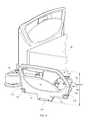
- a hospital bed 10 having a longitudinally extending centerline 20extends longitudinally from a head end 12 to a foot end 14 and laterally from a left side 16 to a right side 18 .
- the bedincludes a base frame 26 and an elevatable frame 28 mounted on the base frame by interframe links 30 .
- the elevatable frameincludes a deck 32 .
- a mattress 34rests on the deck. Casters 38 extend from the base frame to the floor 40 .
- the bedalso includes left and right head end siderails 50 , 52 and left and right foot end siderails 54 , 56 .
- the head end siderailsare substantially mirror images of each other.
- the foot end siderailsare substantially mirror images of each other.
- Each head end sideraildiffers from its neighboring foot end siderail, however the differences do not extend to the variable height attribute described herein. Accordingly it will suffice to describe only one siderail in detail.
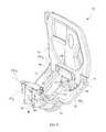
- right side head end siderail 52includes a rail 70 having a lower edge 72 extending longitudinally from a rail head end 74 to a rail foot end 76 , thereby defining the longitudinal extent L of the lower edge.
- a longitudinally outer link 80comprises a head side outer link segment 82 and a foot side outer link segment 84 .
- Each outer link segmentis connected to the rail at joints OR and to the host frame 28 at joints OF.
- An inner link 110having a laterally outer side 112 , a laterally inner side 114 , a head side edge 116 and a foot side edge 118 resides longitudinally intermediate the outer link segments 82 , 84 .
- the inner linkis connected to rail 70 at a joint IR and to host frame 28 at a joint IF.
- the joints IR, OR, IF, and OFdefine pivot axes IR X , OR X , IF X , OF X that extend parallel to centerline 20 .
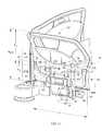
- Joints IR and ORare laterally displaceable relative to the frame such that rail 70 , outer link 80 , inner link 110 and frame 28 comprise a four bar linkage enabling movement of the rail between a deployed or raised position ( FIGS. 3 , 5 , 7 - 9 ) and a stored or lowered position ( FIGS. 4 , 10 ). The progression from the deployed position to the stowed position is seen best in the sequence of views of FIGS. 7-10 .
- Each outer link segment 82 , 84has a frame end 88 , a rail end 90 and an elbow portion 92 extending between the frame and rail ends.
- the frame end 88 of each segmentis connected to frame 28 at joints OF.
- the frame end 88 of each outer link segmenthas a longitudinally inboard edge 96 and a longitudinally outboard edge 98 , the longitudinally inboard edge 96 being longitudinally closer to inner link 110 , and the longitudinally outboard 98 edge being longitudinally further away from the inner link.
- the rail end 90 of each outer link segmentextends from joint OR in a direction nonparallel to that of the frame end 88 . For example, when the siderail is in the deployed state as seen in FIG. 7 , the frame end 88 of each outer link segment is oriented approximately horizontally while the rail end 90 is oriented substantially vertically.
- the rail end of each outer link segmentincludes a wing portion 94 having a top edge 106 .
- the rail ends 90 of the outer link segmentsextend longitudinally toward the inner link, but not far enough to overlap the inner link, even partially.
- the rail end of the head side outer link segment 82extends longitudinally from approximately the head end 74 of the rail lower edge, toward the inner link, and terminates at a terminus 100 longitudinally outboard of the inner link.
- each outer link segment 82 , 84in addition to being connected to rail 70 at a joint OR, is also connected to rail 70 at a joint P near the longitudinal ends 74 , 76 of the rail.
- Joint Pis a joint between the rail 70 and the wing portion 94 of rail end 90 of each link segment.
- Joint Pdefines a pivot axis P X which is common with pivot axis OR X of joint OR.
- Rail end 90 of each outer link segmenthas a top edge 106 spaced from rail lower edge 72 along substantially all of the longitudinal extent of the rail end of the outer link thereby defining interedge space 130 .
- the presence of inter-edge space 130addresses a pinch risk that would be formed by edges 72 , 106 if they were separated by a smaller distance.
- any pinch riskis limited to the regions 132 where the wing portions 94 are in close proximity to the rail in order to be connected thereto at joint P.
- the spacealso facilitates cleaning.
- a larger space 130will be more advantageous for limiting pinch risk and facilitating cleaning; a smaller space will be less advantageous.
- the size of space 130may be determined by the siderail designer or prescribed by regulation or voluntary standards. As is evident from FIGS. 7-10 , adequate inter-edge spacing is maintained throughout the range of travel of the rail from deployed to stored.
- each outer linkIn the deployed state (e.g. FIG. 7 ) the rail end of each outer link, including wing portion 94 , extends substantially vertically relative to the rail. Consequently the siderail 52 has an effective height h UP defined by a height h 1 of the rail and a height h 2 of the rail end of the outer link segments.
- h UPAs the siderail is lowered ( FIGS. 8 , 9 ) to a fully stored state ( FIG. 10 or FIG. 4 ) the rail end of each outer link panel, including wing portion 94 , folds up laterally inwardly of the rail (i.e. behind the rail). Consequently, the siderail, when in the stored state, has an effective height h DOWN which is less than h UP .
- no part of the outer link segments 82 , 84projects vertically below lower edge 72 of the rail when the siderail is in the stored state. Accordingly, the outer link segments make no contribution to the height h DOWN .
- the smaller effective height h DOWNprovides additional latitude for a bed occupant to position his heels under his center of gravity, which is desirable when a bed occupant is moving out of or into the bed by way of a sitting position with his or her legs draped over the side of the bed.
- the smaller effective heightalso offers an improved line of sight and access to foot pedal controls, such as foot pedals 42 ( FIG. 1 ).
- a siderail 52 ′comprises a rail 70 ′ having an upper panel 70 and a lower panel 94 ′.
- the upper panel lower edge 72extends longitudinally from upper panel head end 74 to upper panel foot end 76 .
- the siderailalso includes longitudinally outer link 80 comprising head side outer link segment 82 and foot side outer link segment 84 .
- Each outer link segmentcomprises the arm 140 comprising frame end, rail end and elbow portions 88 , 90 , 92 respectively, and the separately manufactured panel 94 ′ affixed to its rail end by fasteners 142 .
- the siderailalso includes inner link 110 longitudinally intermediate the outer link segments. The inner link is connected to the upper panel 70 at joint IR and to the host frame 78 at joint IF.
- the rail lower panel 94comprises head side and foot side subpanels 94 ′H, 94 ′F, each of which is connected to one of the outer link segments by the fasteners 142 so that the subpanels, and therefore the lower panel 94 ′ as a whole, are stationary with respect to the outer link 80 .
- the lower panelextends longitudinally from substantially the head end 74 to the foot end 76 of the upper panel lower edge 72 without longitudinally overlapping or crossing over the laterally outer side 112 of the inner link.
- the illustrated lower panelavoids crossing over the inner link by virtue of the twin panel construction in which subpanel 94 ′H extends longitudinally footwardly toward the inner link but has a terminus 100 longitudinally outboard of head side edge 116 of the inner link, and subpanel 94 ′F extends longitudinally headwardly toward the inner link but has a terminus 102 longitudinally outboard of inner link foot side edge 118 .
- each subpanel 94 ′H, 94 ′Fin addition to being connected to one of the arms 140 , may also be pivotably connected to upper panel 70 at joint P.
- the lower panelmakes no contribution to the height h DOWN .
- FIGS. 13-14show a bed with siderails whose physical configuration differs from that of the siderails shown in FIGS. 1-12 .
- the space 130 between the wing portion of the outer link segments and the railis smaller than the space 130 of FIGS. 1-12 .
- the differences in appearancedo not affect the variable height attribute already described herein.
Landscapes
- Health & Medical Sciences (AREA)
- Nursing (AREA)
- Life Sciences & Earth Sciences (AREA)
- Animal Behavior & Ethology (AREA)
- General Health & Medical Sciences (AREA)
- Public Health (AREA)
- Veterinary Medicine (AREA)
- Invalid Beds And Related Equipment (AREA)
Abstract
Description
Claims (17)
Priority Applications (2)
| Application Number | Priority Date | Filing Date | Title |
|---|---|---|---|
| US13/733,980US8646131B2 (en) | 2010-07-30 | 2013-01-04 | Variable height siderail |
| US14/176,188US9060619B2 (en) | 2010-07-09 | 2014-02-10 | Variable height siderail |
Applications Claiming Priority (4)
| Application Number | Priority Date | Filing Date | Title |
|---|---|---|---|
| US36915210P | 2010-07-30 | 2010-07-30 | |
| US36949910P | 2010-07-30 | 2010-07-30 | |
| PCT/US2011/043392WO2012006545A2 (en) | 2010-07-09 | 2011-07-08 | Person support systems, devices, and methods |
| US13/733,980US8646131B2 (en) | 2010-07-30 | 2013-01-04 | Variable height siderail |
Related Parent Applications (1)
| Application Number | Title | Priority Date | Filing Date |
|---|---|---|---|
| PCT/US2011/043392ContinuationWO2012006545A2 (en) | 2010-07-09 | 2011-07-08 | Person support systems, devices, and methods |
Related Child Applications (1)
| Application Number | Title | Priority Date | Filing Date |
|---|---|---|---|
| US14/176,188ContinuationUS9060619B2 (en) | 2010-07-09 | 2014-02-10 | Variable height siderail |
Publications (2)
| Publication Number | Publication Date |
|---|---|
| US20130117934A1 US20130117934A1 (en) | 2013-05-16 |
| US8646131B2true US8646131B2 (en) | 2014-02-11 |
Family
ID=48279244
Family Applications (2)
| Application Number | Title | Priority Date | Filing Date |
|---|---|---|---|
| US13/733,980ActiveUS8646131B2 (en) | 2010-07-09 | 2013-01-04 | Variable height siderail |
| US14/176,188ActiveUS9060619B2 (en) | 2010-07-09 | 2014-02-10 | Variable height siderail |
Family Applications After (1)
| Application Number | Title | Priority Date | Filing Date |
|---|---|---|---|
| US14/176,188ActiveUS9060619B2 (en) | 2010-07-09 | 2014-02-10 | Variable height siderail |
Country Status (1)
| Country | Link |
|---|---|
| US (2) | US8646131B2 (en) |
Cited By (2)
| Publication number | Priority date | Publication date | Assignee | Title |
|---|---|---|---|---|
| US9060619B2 (en) | 2010-07-09 | 2015-06-23 | Hill-Rom Services, Inc. | Variable height siderail |
| US20190350780A1 (en)* | 2018-05-21 | 2019-11-21 | Hill-Rom Services, Inc. | Patient support apparatus adaptable to multiple modes of transport |
Families Citing this family (8)
| Publication number | Priority date | Publication date | Assignee | Title |
|---|---|---|---|---|
| USD804885S1 (en)* | 2016-05-28 | 2017-12-12 | Hill-Rom Services, Inc. | Headboard |
| USD804884S1 (en) | 2016-05-28 | 2017-12-12 | Hill-Rom Services, Inc. | Footboard |
| USD812401S1 (en)* | 2016-05-28 | 2018-03-13 | Hill-Rom Services, Inc. | Headboard |
| WO2018074936A1 (en)* | 2016-10-19 | 2018-04-26 | Howard Wright Limited | A side rail |
| CN106691747B (en)* | 2016-12-17 | 2019-02-01 | 莱州科亿宏电动床有限公司 | A kind of medical bed with the fitting closestool that floats |
| JP7185561B2 (en)* | 2019-02-27 | 2022-12-07 | パラマウントベッド株式会社 | bed equipment |
| USD1006516S1 (en)* | 2021-02-11 | 2023-12-05 | Linet Spol. S R.O. | Bed |
| USD1058214S1 (en)* | 2021-09-15 | 2025-01-21 | Linet Spol. S.R.O. | Bed |
Citations (10)
| Publication number | Priority date | Publication date | Assignee | Title |
|---|---|---|---|---|
| US20020144348A1 (en) | 2000-12-29 | 2002-10-10 | Ganance Francis C. | Bed siderail apparatus |
| US7028352B2 (en) | 2001-08-22 | 2006-04-18 | Hill-Rom Services, Inc. | Apparatus and method for closing hospital bed gaps |
| US7073220B2 (en)* | 2002-09-06 | 2006-07-11 | Hill-Rom Services, Inc. | Bed siderail having a latch |
| US7350248B2 (en) | 2000-10-19 | 2008-04-01 | Hill-Rom Sas | Bed with articulated barrier elements |
| US7676862B2 (en) | 2004-09-13 | 2010-03-16 | Kreg Medical, Inc. | Siderail for hospital bed |
| EP2210529A1 (en) | 2007-11-13 | 2010-07-28 | Paramount Bed Co., Ltd. | Folding side rail |
| US20120023666A1 (en) | 2010-07-30 | 2012-02-02 | Heimbrock Richard H | Siderail assembly for patient support apparatus |
| US20120023667A1 (en) | 2010-07-30 | 2012-02-02 | Wiggins Brian T | Variable Height Siderail |
| US20120102643A1 (en) | 2010-11-03 | 2012-05-03 | Turner Jonathan D | Siderail assembly for patient support apparatus |
| US20120144583A1 (en) | 2010-12-08 | 2012-06-14 | Turner Jonathan D | Siderail movable to separate chair egress position |
Family Cites Families (191)
| Publication number | Priority date | Publication date | Assignee | Title |
|---|---|---|---|---|
| US421656A (en) | 1890-02-18 | Removable siding for beds | ||
| US2710976A (en) | 1955-06-21 | martensen | ||
| US993119A (en) | 1910-04-22 | 1911-05-23 | Percival D Stannard | Footboard-quilt. |
| US1398203A (en) | 1921-02-19 | 1921-11-22 | Henry A Schmidt | Convertible bed-spring |
| US2164484A (en) | 1937-03-10 | 1939-07-04 | Joseph A Wolfe | Detachable side panel for beds |
| US2136088A (en) | 1937-08-17 | 1938-11-08 | Frank A Hall & Sons | Bed attachment |
| US2281209A (en) | 1938-07-29 | 1942-04-28 | Smith Orville Dale | Combination bed and carriage |
| US2452366A (en) | 1944-08-11 | 1948-10-26 | Robert R Freund | Patient adjustable foot section for articulated beds |
| US2556591A (en) | 1946-02-06 | 1951-06-12 | Walter M Loxley | Invalid bed |
| US2644173A (en) | 1948-03-13 | 1953-07-07 | Wallace O James | Impervious sheet with inflatable sides |
| US2587291A (en) | 1948-10-25 | 1952-02-26 | Rochers Jean B Des | Folding bed guard |
| US2605151A (en) | 1949-03-23 | 1952-07-29 | Shampaine Hyman Robert | Obstetrical and delivery operating table |
| US2564083A (en) | 1949-04-21 | 1951-08-14 | Alfred H W Stechert | Invalid's bed with manual control |
| US2722017A (en) | 1951-11-16 | 1955-11-01 | Hill Rom Co Inc | Side guards for hospital beds |
| US2766463A (en) | 1952-02-19 | 1956-10-16 | Bendersky Sadie | Means for converting a bed to a chair |
| US2817854A (en) | 1954-10-04 | 1957-12-31 | Edmond O Pratt | Guard attachment for beds |
| US2817855A (en) | 1955-04-08 | 1957-12-31 | Edmond O Pratt | Adjustable fence attachment for beds |
| US2869614A (en) | 1955-05-25 | 1959-01-20 | Floyd B Wamsley | Combination wheel chair and stretcher |
| US3010121A (en) | 1957-04-12 | 1961-11-28 | Roy Frederick Thompson | Adjustable support device |
| US2951252A (en) | 1958-07-25 | 1960-09-06 | Harvard Mfg Company | Bedframe side rail end cap |
| US3021534A (en) | 1958-12-24 | 1962-02-20 | Simmons Co | Adjustable bed rails |
| US3018492A (en) | 1959-04-22 | 1962-01-30 | Rosen Norman | Protective bumper device |
| US3053568A (en) | 1960-02-05 | 1962-09-11 | Clarence A Silva | Chair-bed combination |
| US3099440A (en) | 1960-09-26 | 1963-07-30 | Ritter Co Inc | Apparatus for controlling the flow of fluids |
| US3055020A (en) | 1961-02-10 | 1962-09-25 | Hard Mfg Co | Restraining structure for beds |
| US3138805A (en) | 1961-04-11 | 1964-06-30 | Salvatore J Piazza | Bed-wheelchair |
| US3233255A (en) | 1961-05-22 | 1966-02-08 | Miller Herman Inc | Bed construction |
| US3112500A (en) | 1961-05-24 | 1963-12-03 | Benjamin R F Macdonald | Hospital bed |
| US3210779A (en) | 1961-09-11 | 1965-10-12 | Ted E Herbold | Multiple position combination chair-bed |
| US3148387A (en) | 1961-09-14 | 1964-09-15 | Jr Michael C Sarnie | Support attachment for sleeping surfaces |
| US3239853A (en) | 1962-01-15 | 1966-03-15 | Benjamin R F Macdonald | Convertible hospital bed-chair |
| DK116534B (en) | 1962-08-23 | 1970-01-19 | A Michelsen | Seating and reclining furniture, especially ottoman with magazine back. |
| US3309717A (en) | 1963-03-20 | 1967-03-21 | American Seating Co | Hospital bed |
| US3220022A (en) | 1963-12-23 | 1965-11-30 | Nelson Ted | Hospital bed sliding foot section |
| US3220021A (en) | 1964-04-09 | 1965-11-30 | Nelson Ted | Adjustable seat length hospital bed |
| US3249387A (en) | 1965-02-16 | 1966-05-03 | Mobilaid Inc | Swinging arm rest |
| FR1450817A (en) | 1965-07-16 | 1966-06-24 | Le Lit Tous Soins | Removable grid for medical beds |
| SE300672B (en) | 1965-09-02 | 1968-05-06 | Redev Ab | |
| CA795223A (en) | 1966-04-11 | 1968-09-24 | M. Tabler John | Baby mattress with attached side pads |
| US3351962A (en) | 1966-07-01 | 1967-11-14 | Bedline Inc | Adjustable guard frame for beds |
| US3344445A (en) | 1966-08-12 | 1967-10-03 | Institutional Ind Inc | Side panel construction for stretcher-beds |
| US3456269A (en) | 1967-10-16 | 1969-07-22 | Robert Goodman | Foldable bed with adjustable contour bed spring |
| US3486176A (en) | 1967-11-16 | 1969-12-30 | Lumex | Safety and patient assist device |
| US3593350A (en) | 1969-03-13 | 1971-07-20 | Dominion Metalware Ind Ltd The | Retractable bed |
| US3640556A (en) | 1969-08-22 | 1972-02-08 | Moreland P Bennett | Tab welded joint and method of making |
| US3585659A (en) | 1969-10-15 | 1971-06-22 | Hill Rom Co Inc | Safety side guard for hospital beds |
| US3619824A (en) | 1970-02-10 | 1971-11-16 | Bunny Bear Inc | Crib bumper |
| US3905591A (en) | 1970-09-24 | 1975-09-16 | Siemens Ag | Patient{3 s couch |
| US3742530A (en) | 1971-06-16 | 1973-07-03 | M Clark | Bedside rail cover |
| US3851345A (en) | 1972-05-17 | 1974-12-03 | Interroyal Corp | Safety side mechanism |
| US3845511A (en) | 1972-08-10 | 1974-11-05 | Interroyal Corp | Universal headboard construction |
| DE2406374A1 (en) | 1973-02-14 | 1975-08-14 | Fritz Kerstholt | Divan with adjustable outer parts - has bearing spring arrangement operated by body weight and locked manually |
| US3897973A (en) | 1973-06-05 | 1975-08-05 | Amerco Inc | Blood drawing chair |
| US3865434A (en) | 1973-07-20 | 1975-02-11 | Everest & Jennings | Rotating wheelchair arm |
| US3893197A (en) | 1974-02-11 | 1975-07-08 | Maurine E Ricke | Hospital bed footboard assembly |
| US3877090A (en) | 1974-04-12 | 1975-04-15 | Fine Art Pillow And Spec Corp | Crib bumper and mattress |
| GB1466080A (en) | 1974-10-30 | 1977-03-02 | Siddall Hilton Ltd | Hospital bed attachments |
| US3971083A (en) | 1974-11-27 | 1976-07-27 | Joerns Furniture Company | Side guard for beds |
| US4127906A (en) | 1976-07-15 | 1978-12-05 | Zur Henry C | Adjustable bed-chair |
| US4258445A (en) | 1976-07-15 | 1981-03-31 | Zur Henry C | Beds and adjustable body supporting assemblies |
| US4139917A (en) | 1977-10-17 | 1979-02-20 | Loel Fenwick | Labor, delivery and patient care bed |
| US4168099A (en) | 1978-03-27 | 1979-09-18 | Midmark Corporation | Multi-position examination chair |
| US4183015A (en) | 1978-06-26 | 1980-01-08 | Hill-Rom Company, Inc. | Side guard for bed including means for controlling remote electrical devices |
| US4186456A (en) | 1978-07-14 | 1980-02-05 | American Hospital Supply Corporation | Rail system for bed or stretcher |
| US4215446A (en) | 1978-08-28 | 1980-08-05 | Patsie Mahoney | Padded hospital bed siderail cover |
| US4240169A (en) | 1979-01-26 | 1980-12-23 | Roos Kjell E | Patient transferring apparatus |
| NL7901576A (en) | 1979-02-28 | 1980-09-01 | Philips Nv | PATIENT CARRIER WITH TILTABLE CARRIERS. |
| US4232415A (en) | 1979-03-19 | 1980-11-11 | Webber Gloria C | Mattress sling |
| US4214326A (en) | 1979-05-31 | 1980-07-29 | Spann Donald C | Body positioner and protection apparatus |
| US4336621A (en) | 1980-02-25 | 1982-06-29 | Schwartz Donald R | Disposable orthopedic overmattress for articulated beds |
| US4332042A (en) | 1980-03-31 | 1982-06-01 | Burlington Industries, Inc. | Geriatric environmental systeming |
| US4370765A (en) | 1980-09-05 | 1983-02-01 | Webber Gloria C | Envelope for a bed having side rails |
| US4439880A (en) | 1980-09-18 | 1984-04-03 | Burlington Industries, Inc. | Geriatric bed construction with sideguards |
| US4409695A (en) | 1981-02-03 | 1983-10-18 | Burke, Inc. | Adjustable bed for morbidly obese patients |
| US4453732A (en) | 1981-12-24 | 1984-06-12 | Assanah Albert A | Patient transport and care vehicle |
| FR2523437A1 (en) | 1982-03-18 | 1983-09-23 | Idetec Entreprise | MEDICAL BED |
| USD276112S (en) | 1982-06-10 | 1984-10-30 | Ferrell Linda S | Hospital bed protective device |
| DE3464696D1 (en) | 1983-08-17 | 1987-08-20 | Moelnlycke Ab | A chair and/or bed arrangement |
| US4612679A (en) | 1984-03-01 | 1986-09-23 | Amedco Health Care Inc. | Bed side guard assembly |
| US4676687A (en) | 1984-03-09 | 1987-06-30 | Henry Koffler | Universal bedside rail clamp |
| US4873734A (en) | 1985-04-15 | 1989-10-17 | Pollard Dianne J | Bumper sheet |
| US4607402A (en) | 1985-04-15 | 1986-08-26 | Pollard Dianne J | Retainer sheet |
| US4776047A (en) | 1985-05-07 | 1988-10-11 | Med Bed Technologies, Inc. | Multiple function invalid bed arrangement |
| US4685159A (en) | 1985-05-09 | 1987-08-11 | Hans Oetiker | Hospital bed |
| DE3682501D1 (en) | 1985-08-13 | 1991-12-19 | William Brian Plewright | VEHICLE FOR PATIENT RELOCATION AND REQUIREMENT. |
| US4745647A (en) | 1985-12-30 | 1988-05-24 | Ssi Medical Services, Inc. | Patient support structure |
| US4768249A (en) | 1985-12-30 | 1988-09-06 | Ssi Medical Services, Inc. | Patient support structure |
| US4672698A (en) | 1986-02-07 | 1987-06-16 | Sands Donald F | Bed rail cushion system |
| US4670923A (en) | 1986-03-17 | 1987-06-09 | Gabriel Janice Y | Transparent crib bumper pads |
| US4653129A (en) | 1986-04-25 | 1987-03-31 | Midmark Corporation | Side rail assembly for a wheeled stretcher |
| US4704750A (en) | 1986-07-07 | 1987-11-10 | Wheelock Barry E | Assembleable, free-standing, bed suspension apparatus |
| US4747171A (en) | 1986-08-12 | 1988-05-31 | Simmons Healthcare, Inc. | Hospital bed rail assembly |
| US4800600A (en) | 1986-08-20 | 1989-01-31 | Baum Marilyn J | Decorative crib bumper |
| YU46743B (en) | 1986-12-02 | 1994-04-05 | Milenko Pupović | BED WITH ADJUSTABLE POSITIONS |
| US4710049A (en) | 1987-01-30 | 1987-12-01 | Virco Mfg. Corporation | Safety hinge |
| US4751754A (en) | 1987-04-02 | 1988-06-21 | Hill-Rom Company, Inc. | Dual hydraulic hospital bed with emergency bypass circuit |
| US4710992A (en) | 1987-05-01 | 1987-12-08 | Falwell Bobby R | Waterbed rail cap |
| US4862530A (en) | 1987-07-27 | 1989-09-05 | Chen Chung C | Convertible bed |
| US4783864A (en) | 1987-08-03 | 1988-11-15 | Turner Ronald L | Producing subconscious integumental reflex action to keep children away from guard rail while sleeping on bunk bed |
| US4974905A (en) | 1987-08-10 | 1990-12-04 | Davis John W | Chair bed |
| US4767419A (en) | 1987-09-28 | 1988-08-30 | Fattore Mary E | Protective pad for crib rail |
| IL85442A (en) | 1988-02-17 | 1992-11-15 | Oded Sheinfeld | Combined bed and relaxation chair |
| US4827545A (en) | 1988-03-09 | 1989-05-09 | Arp Norman T | Removable protective covering assembly for a bed restraining side rail |
| US4858260A (en) | 1988-03-11 | 1989-08-22 | Hausted, Inc. | Patient transport apparatus including Trendelenburg mechanism and guard rail |
| WO1989009590A1 (en) | 1988-03-23 | 1989-10-19 | Robert Ferrand | Patient support system |
| US4872228A (en) | 1988-06-27 | 1989-10-10 | Bishop Carolyn B | Bed guard |
| US4862529A (en) | 1988-07-13 | 1989-09-05 | Hill-Rom Company, Inc. | Hospital bed convertible to chair |
| US4894876A (en) | 1988-07-15 | 1990-01-23 | Hill-Rom Company, Inc. | Multipurpose maternity care bed |
| US5216768A (en) | 1988-11-17 | 1993-06-08 | Oliver H. Bodine, Jr. | Bed system |
| US5010611A (en) | 1989-06-07 | 1991-04-30 | Sarah Mallett | Fitted safety crib sheet with integral bumper liner |
| WO1991000079A1 (en) | 1989-06-26 | 1991-01-10 | Tadashi Iura | Bed |
| US5083332A (en) | 1989-07-28 | 1992-01-28 | Hill-Rom Company, Inc. | Hospital bed with collapsible side edges and laterally-movable side guards |
| US5179744A (en) | 1989-07-28 | 1993-01-19 | Hill-Rom Company, Inc. | Hospital bed with inflatable and collapsible side edges and laterally-movable side guards |
| US5077843A (en) | 1990-07-28 | 1992-01-07 | Hill-Rom Company, Inc. | Hospital bed and assemblies of hospital care apparatus |
| US4985946A (en) | 1989-07-28 | 1991-01-22 | Hill-Rom Company, Inc. | Hospital bed adapted for use with a C-arm |
| US4993089A (en) | 1990-03-21 | 1991-02-19 | Amfab, Incorporated, Division Of Bissell, Inc. | Bed rail mechanism |
| US5577279A (en) | 1990-05-16 | 1996-11-26 | Hill-Rom Company, Inc. | Hospital bed |
| US5454126A (en) | 1994-01-25 | 1995-10-03 | Hill-Rom Company, Inc. | Foot egress chair bed |
| US5479666A (en) | 1994-01-25 | 1996-01-02 | Hill-Rom Company, Inc. | Foot egress chair bed |
| US5040253A (en) | 1990-07-16 | 1991-08-20 | Cheng Yen Feng | Variable bed having multiple functions |
| US5035014A (en) | 1990-08-10 | 1991-07-30 | Ssi Medical Services, Inc. | Comfort guard for low air loss patient support systems |
| US5083334A (en) | 1990-10-12 | 1992-01-28 | Ssi Medical Services, Inc. | Side guard for patient support |
| US5060327A (en) | 1990-10-18 | 1991-10-29 | Hill-Rom Company, Inc. | Labor grips for birthing bed |
| GB2250189B (en) | 1990-11-28 | 1993-11-24 | Nesbit Evans & Co Ltd | Beds |
| US5129117A (en)* | 1990-11-28 | 1992-07-14 | Hill-Rom Company, Inc. | Birth assist protection guard |
| USD336577S (en) | 1990-12-17 | 1993-06-22 | Hill-Rom Company, Inc. | Sideguard for a birthing bed |
| US5084925A (en) | 1991-02-19 | 1992-02-04 | Product Strategies, Inc. | Hospital bed guard extender |
| US5072463A (en) | 1991-04-11 | 1991-12-17 | Willis William J | EZ access bed |
| US5193633A (en) | 1991-06-07 | 1993-03-16 | Wright State University | Motorized transfer and transport system for the disabled |
| US5175897A (en) | 1991-06-17 | 1993-01-05 | Marra Jr John J | Cover for hospital bed rails |
| US5097550A (en) | 1991-06-17 | 1992-03-24 | Marra Jr John J | Cover for hospital bed rails |
| US5197156A (en) | 1991-07-31 | 1993-03-30 | Stryker Corporation | Transfer board support lever and support post |
| US5230113A (en) | 1992-04-14 | 1993-07-27 | Good Turn, Inc. | Multiple position adjustable day night patient bed chair |
| US5191663A (en) | 1992-07-02 | 1993-03-09 | Hill-Rom Company, Inc. | Hospital bed sideguard pads |
| US5384927A (en) | 1993-01-27 | 1995-01-31 | Canadian Aging & Rehabilitation Product Development Corp. | Security rail attachment for a bed |
| US5381571A (en) | 1993-04-13 | 1995-01-17 | Gabhart; Thomas S. | Pivotable and lockable hospital bed guard |
| US5365623A (en) | 1993-08-27 | 1994-11-22 | Springer Maurice D | Telephone holder for bed side rail |
| US5410765A (en) | 1993-11-24 | 1995-05-02 | Youngblood; Kevin | Crib bumper pad |
| US5715548A (en) | 1994-01-25 | 1998-02-10 | Hill-Rom, Inc. | Chair bed |
| US5537701A (en) | 1994-03-15 | 1996-07-23 | Maxwell Products, Inc. | Adjustable articulated bed |
| US5481772A (en) | 1994-03-24 | 1996-01-09 | Glynn; William D. | Bed rail apparatus |
| US5421046A (en) | 1994-05-04 | 1995-06-06 | Vande Streek; Janet L. | Bed bumper pad |
| US5524306A (en) | 1994-05-20 | 1996-06-11 | Morales, George Hector | Bed restraint |
| US5455973A (en) | 1994-05-23 | 1995-10-10 | Brumfield; Barbara A. | Cushion cover with adjustable peripheral sideguard |
| US5450641A (en) | 1994-06-21 | 1995-09-19 | Connecticut Artcraft Corp | Inflatable bed rail guard |
| US5575025A (en) | 1994-11-14 | 1996-11-19 | Peters; Michael J. | Gurney with protective cover |
| US6212714B1 (en) | 1995-01-03 | 2001-04-10 | Hill-Rom, Inc. | Hospital bed and mattress having a retracting foot section |
| US5577277A (en) | 1995-03-30 | 1996-11-26 | Safety 1St, Inc. | Collapsable bed side rail |
| US5542135A (en) | 1995-05-15 | 1996-08-06 | Safe Surroundings, Inc. | Self-retaining bumper pad |
| US5678267A (en) | 1995-07-11 | 1997-10-21 | Kinder; Florence E. | Medical examination table handle system |
| US5557817A (en) | 1995-07-14 | 1996-09-24 | Haddock; Henry J. | Protective cover for hospital bed rails |
| US5732423A (en) | 1995-08-04 | 1998-03-31 | Hill-Rom, Inc. | Bed side rails |
| US5630238A (en) | 1995-08-04 | 1997-05-20 | Hill-Rom, Inc. | Bed with a plurality of air therapy devices, having control modules and an electrical communication network |
| US5926873A (en) | 1995-08-21 | 1999-07-27 | Fountain; Irene | Crib railing guard |
| ATE164498T1 (en) | 1995-12-18 | 1998-04-15 | Le Couviour Sa | BED SIDE PART |
| US5642545A (en) | 1996-05-13 | 1997-07-01 | Howard; Bridget | Fitted crib pads adapted to cover horizontal and vertical rails |
| US5781945A (en) | 1996-05-20 | 1998-07-21 | Brk Brands, Inc. | Portable foldable bed rail |
| GB2313303B (en) | 1996-05-20 | 2000-04-12 | Egerton Hospital Equip | Improvements in and relating to beds |
| CA2181021C (en) | 1996-07-11 | 2007-10-02 | Eric Laganiere | Split side guards |
| US5749112A (en) | 1996-09-30 | 1998-05-12 | Metzler; Donald L. | Invalid bed guard sheet |
| US5771506A (en) | 1996-10-22 | 1998-06-30 | Joiner; Glenda P. | Protection apparatus |
| ATE256986T1 (en) | 1996-10-23 | 2004-01-15 | Hill Rom Services Inc | INTEGRATED SIDE RAIL AND ACCESSORIES CARRYING DEVICE FOR A BED |
| US5802636A (en) | 1996-11-12 | 1998-09-08 | Hill-Rom, Inc. | Integrated siderail and accessory rail for a bed |
| US5761756A (en) | 1996-10-25 | 1998-06-09 | The First Years Inc. | Portable bed rail |
| US5671490A (en) | 1996-11-13 | 1997-09-30 | Wu; Sung-Tsun | Collapsible bed rail structure |
| US5878452A (en) | 1996-12-03 | 1999-03-09 | Hill-Rom, Inc. | Long term care bed controls |
| US6089593A (en) | 1997-02-10 | 2000-07-18 | Hill-Rom, Inc. | Ambulatory care chair |
| US6058531A (en) | 1997-05-23 | 2000-05-09 | Carroll Intelli Corp. | Dual-position assist and guard rail for beds |
| US5864900A (en) | 1998-01-12 | 1999-02-02 | Landau; James | Patient-protective side panel for beds |
| US6286166B1 (en) | 1998-06-19 | 2001-09-11 | Hill-Rom Services, Inc. | Modular foam mattress |
| US6038721A (en) | 1998-10-05 | 2000-03-21 | Gordon; Illinois J. | Split rail bed guard system |
| DE19900602C1 (en) | 1999-01-11 | 2000-07-13 | Wissner Bosserhoff Gmbh | Sickbed side guard with top and bottom positions swings down via axis or gearwheel guided to the belt round half circle swivel shaft using co-ordinated stop to arrest raised guard position. |
| US6401277B1 (en) | 1999-03-12 | 2002-06-11 | Hill-Rom Services, Inc. | Siderail extender |
| US5987666A (en) | 1999-03-15 | 1999-11-23 | St. Luke Foundation | Gap-filling pad disposable between a mattress and a bed rail |
| US6427264B1 (en) | 1999-03-19 | 2002-08-06 | Hill-Rom Services, Inc. | Gap filler for bed |
| US6374440B1 (en) | 1999-04-20 | 2002-04-23 | Arthur W. Thim, Jr. | Back support |
| CA2311187A1 (en) | 1999-08-12 | 2001-02-12 | Hill-Rom, Inc. | Ambulatory assist arm for a bed |
| US6347422B2 (en) | 2000-04-19 | 2002-02-19 | Thomas Heavrin | Bed pads |
| US6401281B1 (en) | 2000-12-08 | 2002-06-11 | Josephine L. Younge | Bed rail pads |
| US7055193B2 (en) | 2002-09-17 | 2006-06-06 | Summer Infant, Inc. | Bed guard assembly |
| US7454804B2 (en) | 2002-09-17 | 2008-11-25 | Summer Infant Inc. | Bed guard assembly |
| US6725476B2 (en) | 2002-09-17 | 2004-04-27 | Summer Infant, Inc. | Bed guard assembly |
| US6959463B2 (en) | 2002-09-17 | 2005-11-01 | Summer Infant, Inc. | Bed guard assembly |
| US7080419B2 (en) | 2002-09-17 | 2006-07-25 | Summer Infant, Inc. | Bed guard assembly |
| US6938289B2 (en) | 2004-01-28 | 2005-09-06 | Stryker Corporation | Siderail mounting assembly |
| CA2523168C (en) | 2004-10-18 | 2014-02-18 | Stryker Corporation | Bed siderail |
| TWM334708U (en) | 2007-07-03 | 2008-06-21 | Optima Healthcare Inc | Handrail mechanism of bed frame |
| FR2918256B1 (en) | 2007-07-06 | 2009-10-09 | Hill Rom Sas Soc Par Actions S | BED OF SICK WITH SIDE BARRIER REMOVABLE. |
| US7930778B2 (en) | 2007-12-07 | 2011-04-26 | Hill-Rom Services, Inc. | Pinch-preventing unit for bed guardrail |
| US8176583B2 (en)* | 2010-03-15 | 2012-05-15 | Hill-Rom Services, Inc. | Siderail assembly |
| US8646131B2 (en) | 2010-07-30 | 2014-02-11 | Hill-Rom Services, Inc. | Variable height siderail |
- 2013
- 2013-01-04USUS13/733,980patent/US8646131B2/enactiveActive
- 2014
- 2014-02-10USUS14/176,188patent/US9060619B2/enactiveActive
Patent Citations (11)
| Publication number | Priority date | Publication date | Assignee | Title |
|---|---|---|---|---|
| US7350248B2 (en) | 2000-10-19 | 2008-04-01 | Hill-Rom Sas | Bed with articulated barrier elements |
| US20080201844A1 (en) | 2000-10-19 | 2008-08-28 | Sebastien Gemeline | Bed With Simultaneously Movable Barrier and Bed Plane Elements |
| US20020144348A1 (en) | 2000-12-29 | 2002-10-10 | Ganance Francis C. | Bed siderail apparatus |
| US7028352B2 (en) | 2001-08-22 | 2006-04-18 | Hill-Rom Services, Inc. | Apparatus and method for closing hospital bed gaps |
| US7073220B2 (en)* | 2002-09-06 | 2006-07-11 | Hill-Rom Services, Inc. | Bed siderail having a latch |
| US7676862B2 (en) | 2004-09-13 | 2010-03-16 | Kreg Medical, Inc. | Siderail for hospital bed |
| EP2210529A1 (en) | 2007-11-13 | 2010-07-28 | Paramount Bed Co., Ltd. | Folding side rail |
| US20120023666A1 (en) | 2010-07-30 | 2012-02-02 | Heimbrock Richard H | Siderail assembly for patient support apparatus |
| US20120023667A1 (en) | 2010-07-30 | 2012-02-02 | Wiggins Brian T | Variable Height Siderail |
| US20120102643A1 (en) | 2010-11-03 | 2012-05-03 | Turner Jonathan D | Siderail assembly for patient support apparatus |
| US20120144583A1 (en) | 2010-12-08 | 2012-06-14 | Turner Jonathan D | Siderail movable to separate chair egress position |
Non-Patent Citations (16)
| Title |
|---|
| Affinity Siderails Photographs dated Dec. 2009, numbered 1-6. |
| Final Office Action for Application No. 13/0233,133, dated Jul. 30, 2013. |
| Information Disclosure Statement By Applicant dated Jan. 24, 2013. |
| Non-Final Office Action for U.S. Appl. No. 13/023,133, dated Feb. 1, 2013. |
| Notice of Appeal From the Examiner to the Patent Trial and Appeal Board, Dated Dec. 2, 2013. |
| PTO-892 from U.S. Appl. No. 13/023,133. |
| Response to Office Action dated Feb. 1, 2013, filed on Jun. 28, 2013. |
| Response to Office Action dated Jul. 30, 2013, filed on Dec. 2, 2013. |
| Service Manual AvantGuard® 1600 Electric bed LI160Ax 149223 Rev. 002. Second edition, Apr. 2010 first printing, Mar. 2008. |
| Service Manual Hill-Rom® Basic Care(TM) Bed, Hill-Rom® 305 Manual Bed, Hill-Rom® 405 Electric Bed From Hill-Rom Product No. P1440/P1441 MAN336 Rev 2. Second Edition Mar. 2008 First Printing May 2004 printed in the USA. |
| Service Manual Hill-Rom® Basic Care™ Bed, Hill-Rom® 305 Manual Bed, Hill-Rom® 405 Electric Bed From Hill-Rom Product No. P1440/P1441 MAN336 Rev 2. Second Edition Mar. 2008 First Printing May 2004 printed in the USA. |
| Services Manual AvantGuard® 1600 Electric bed with weigh system L1160A2. 155725 Rev. 003. Third edition, Apr. 2010, first printing 2009. |
| User Manual Affinity® Three Birthing Bed and Affinity® Four Birthing Bed From Hill-Rom Product No. P3700 USR025 Rev 4. Dec. 2009. |
| User Manual AvantGuard® 1600/L1160Ax Electric Bed, 149214 Rev. 006, Mar. 2010. |
| User Manual Hill-Rom® Basic Care(TM) Bed, Hill-Rom® 405 Electric Bed From Hill-Rom Product No. P1440/P1441 USR124 Rev 7. Seventh Edition Dec. 2007, first Printing Mar. 2004. |
| User Manual Hill-Rom® Basic Care™ Bed, Hill-Rom® 405 Electric Bed From Hill-Rom Product No. P1440/P1441 USR124 Rev 7. Seventh Edition Dec. 2007, first Printing Mar. 2004. |
Cited By (5)
| Publication number | Priority date | Publication date | Assignee | Title |
|---|---|---|---|---|
| US9060619B2 (en) | 2010-07-09 | 2015-06-23 | Hill-Rom Services, Inc. | Variable height siderail |
| US20190350780A1 (en)* | 2018-05-21 | 2019-11-21 | Hill-Rom Services, Inc. | Patient support apparatus adaptable to multiple modes of transport |
| US11628102B2 (en)* | 2018-05-21 | 2023-04-18 | Hill-Rom Services, Inc. | Patient support apparatus adaptable to multiple modes of transport |
| US20230248593A1 (en)* | 2018-05-21 | 2023-08-10 | Hill-Rom Services, Inc. | Patient support apparatus having detachable barrier assembly |
| US12336941B2 (en)* | 2018-05-21 | 2025-06-24 | Hill-Rom Services, Inc. | Patient support apparatus having detachable barrier assembly |
Also Published As
| Publication number | Publication date |
|---|---|
| US20140150180A1 (en) | 2014-06-05 |
| US20130117934A1 (en) | 2013-05-16 |
| US9060619B2 (en) | 2015-06-23 |
Similar Documents
| Publication | Publication Date | Title |
|---|---|---|
| US8646131B2 (en) | Variable height siderail | |
| US8607384B2 (en) | Bed frame assembly with a lift system having a translatable carriage | |
| US8732875B2 (en) | Patient support apparatus with movable siderail assembly | |
| US20110010861A1 (en) | Transition Assist Siderail and Article Employing the Same | |
| US8621688B2 (en) | Siderail assembly for patient support apparatus | |
| US8732876B2 (en) | Upper body support mechanism | |
| EP0850038B1 (en) | Bed having a reduced-shear pivot and step deck combination | |
| EP1988867B1 (en) | Articulating bed | |
| US8745786B2 (en) | Siderail assembly for patient support apparatus | |
| US8713727B2 (en) | Siderail assembly for patient support apparatus | |
| US8176583B2 (en) | Siderail assembly | |
| US9629768B2 (en) | Variable height siderail | |
| US20120124746A1 (en) | Patient support apparatus with egress units | |
| US8973187B2 (en) | Bed frame assembly with a lift system having a translatable carriage | |
| US20130086746A1 (en) | Patient support apparatus with movable siderail assembly | |
| US20120084922A1 (en) | Patient support apparatus with storable egress handles | |
| US20030229941A1 (en) | Bed, particularly a hospital or nursing bed | |
| US20120144583A1 (en) | Siderail movable to separate chair egress position | |
| US20180000253A1 (en) | Motorized mechanism and motorized furniture | |
| US20110088167A1 (en) | Hospital bed with adjustable sleeping surface | |
| US7712165B2 (en) | Bed with a retractable side barrier | |
| US12016808B2 (en) | Patient support apparatus having patient support deck and gap covering deck section | |
| US10098797B2 (en) | Endboard for a person support apparatus | |
| JP6581459B2 (en) | Bed equipment | |
| US20250213047A1 (en) | Adjustable Bed Base With Decline Feature On Both Ends |
Legal Events
| Date | Code | Title | Description |
|---|---|---|---|
| AS | Assignment | Owner name:HILL-ROM SERVICES, INC. (INDIANA CORPORATION), IND Free format text:CHANGE OF STATE OF INCORPORATION FROM DELAWARE TO INDIANA;ASSIGNOR:HILL-ROM SERVICES, INC. (DELAWARE CORPORATION);REEL/FRAME:031910/0627 Effective date:20101228 | |
| STCF | Information on status: patent grant | Free format text:PATENTED CASE | |
| AS | Assignment | Owner name:JPMORGAN CHASE BANK, N.A., AS COLLATERAL AGENT, ILLINOIS Free format text:SECURITY INTEREST;ASSIGNORS:ALLEN MEDICAL SYSTEMS, INC.;HILL-ROM SERVICES, INC.;ASPEN SURGICAL PRODUCTS, INC.;AND OTHERS;REEL/FRAME:036582/0123 Effective date:20150908 Owner name:JPMORGAN CHASE BANK, N.A., AS COLLATERAL AGENT, IL Free format text:SECURITY INTEREST;ASSIGNORS:ALLEN MEDICAL SYSTEMS, INC.;HILL-ROM SERVICES, INC.;ASPEN SURGICAL PRODUCTS, INC.;AND OTHERS;REEL/FRAME:036582/0123 Effective date:20150908 | |
| AS | Assignment | Owner name:JPMORGAN CHASE BANK, N.A., AS COLLATERAL AGENT, ILLINOIS Free format text:SECURITY AGREEMENT;ASSIGNORS:HILL-ROM SERVICES, INC.;ASPEN SURGICAL PRODUCTS, INC.;ALLEN MEDICAL SYSTEMS, INC.;AND OTHERS;REEL/FRAME:040145/0445 Effective date:20160921 Owner name:JPMORGAN CHASE BANK, N.A., AS COLLATERAL AGENT, IL Free format text:SECURITY AGREEMENT;ASSIGNORS:HILL-ROM SERVICES, INC.;ASPEN SURGICAL PRODUCTS, INC.;ALLEN MEDICAL SYSTEMS, INC.;AND OTHERS;REEL/FRAME:040145/0445 Effective date:20160921 | |
| FPAY | Fee payment | Year of fee payment:4 | |
| AS | Assignment | Owner name:WELCH ALLYN, INC., NEW YORK Free format text:RELEASE BY SECURED PARTY;ASSIGNOR:JPMORGAN CHASE BANK, N.A.;REEL/FRAME:050254/0513 Effective date:20190830 Owner name:HILL-ROM, INC., ILLINOIS Free format text:RELEASE BY SECURED PARTY;ASSIGNOR:JPMORGAN CHASE BANK, N.A.;REEL/FRAME:050254/0513 Effective date:20190830 Owner name:VOALTE, INC., FLORIDA Free format text:RELEASE BY SECURED PARTY;ASSIGNOR:JPMORGAN CHASE BANK, N.A.;REEL/FRAME:050254/0513 Effective date:20190830 Owner name:ALLEN MEDICAL SYSTEMS, INC., ILLINOIS Free format text:RELEASE BY SECURED PARTY;ASSIGNOR:JPMORGAN CHASE BANK, N.A.;REEL/FRAME:050254/0513 Effective date:20190830 Owner name:MORTARA INSTRUMENT, INC., WISCONSIN Free format text:RELEASE BY SECURED PARTY;ASSIGNOR:JPMORGAN CHASE BANK, N.A.;REEL/FRAME:050254/0513 Effective date:20190830 Owner name:HILL-ROM COMPANY, INC., ILLINOIS Free format text:RELEASE BY SECURED PARTY;ASSIGNOR:JPMORGAN CHASE BANK, N.A.;REEL/FRAME:050254/0513 Effective date:20190830 Owner name:MORTARA INSTRUMENT SERVICES, INC., WISCONSIN Free format text:RELEASE BY SECURED PARTY;ASSIGNOR:JPMORGAN CHASE BANK, N.A.;REEL/FRAME:050254/0513 Effective date:20190830 Owner name:ANODYNE MEDICAL DEVICE, INC., FLORIDA Free format text:RELEASE BY SECURED PARTY;ASSIGNOR:JPMORGAN CHASE BANK, N.A.;REEL/FRAME:050254/0513 Effective date:20190830 Owner name:HILL-ROM SERVICES, INC., ILLINOIS Free format text:RELEASE BY SECURED PARTY;ASSIGNOR:JPMORGAN CHASE BANK, N.A.;REEL/FRAME:050254/0513 Effective date:20190830 | |
| AS | Assignment | Owner name:JPMORGAN CHASE BANK, N.A., ILLINOIS Free format text:SECURITY AGREEMENT;ASSIGNORS:HILL-ROM HOLDINGS, INC.;HILL-ROM, INC.;HILL-ROM SERVICES, INC.;AND OTHERS;REEL/FRAME:050260/0644 Effective date:20190830 | |
| MAFP | Maintenance fee payment | Free format text:PAYMENT OF MAINTENANCE FEE, 8TH YEAR, LARGE ENTITY (ORIGINAL EVENT CODE: M1552); ENTITY STATUS OF PATENT OWNER: LARGE ENTITY Year of fee payment:8 | |
| AS | Assignment | Owner name:HILL-ROM HOLDINGS, INC., ILLINOIS Free format text:RELEASE OF SECURITY INTEREST AT REEL/FRAME 050260/0644;ASSIGNOR:JPMORGAN CHASE BANK, N.A.;REEL/FRAME:058517/0001 Effective date:20211213 Owner name:BARDY DIAGNOSTICS, INC., ILLINOIS Free format text:RELEASE OF SECURITY INTEREST AT REEL/FRAME 050260/0644;ASSIGNOR:JPMORGAN CHASE BANK, N.A.;REEL/FRAME:058517/0001 Effective date:20211213 Owner name:VOALTE, INC., FLORIDA Free format text:RELEASE OF SECURITY INTEREST AT REEL/FRAME 050260/0644;ASSIGNOR:JPMORGAN CHASE BANK, N.A.;REEL/FRAME:058517/0001 Effective date:20211213 Owner name:HILL-ROM, INC., ILLINOIS Free format text:RELEASE OF SECURITY INTEREST AT REEL/FRAME 050260/0644;ASSIGNOR:JPMORGAN CHASE BANK, N.A.;REEL/FRAME:058517/0001 Effective date:20211213 Owner name:WELCH ALLYN, INC., NEW YORK Free format text:RELEASE OF SECURITY INTEREST AT REEL/FRAME 050260/0644;ASSIGNOR:JPMORGAN CHASE BANK, N.A.;REEL/FRAME:058517/0001 Effective date:20211213 Owner name:ALLEN MEDICAL SYSTEMS, INC., ILLINOIS Free format text:RELEASE OF SECURITY INTEREST AT REEL/FRAME 050260/0644;ASSIGNOR:JPMORGAN CHASE BANK, N.A.;REEL/FRAME:058517/0001 Effective date:20211213 Owner name:HILL-ROM SERVICES, INC., ILLINOIS Free format text:RELEASE OF SECURITY INTEREST AT REEL/FRAME 050260/0644;ASSIGNOR:JPMORGAN CHASE BANK, N.A.;REEL/FRAME:058517/0001 Effective date:20211213 Owner name:BREATHE TECHNOLOGIES, INC., CALIFORNIA Free format text:RELEASE OF SECURITY INTEREST AT REEL/FRAME 050260/0644;ASSIGNOR:JPMORGAN CHASE BANK, N.A.;REEL/FRAME:058517/0001 Effective date:20211213 | |
| MAFP | Maintenance fee payment | Free format text:PAYMENT OF MAINTENANCE FEE, 12TH YEAR, LARGE ENTITY (ORIGINAL EVENT CODE: M1553); ENTITY STATUS OF PATENT OWNER: LARGE ENTITY Year of fee payment:12 |