US8644894B2 - Mobile wireless device with multi-band antenna and related methods - Google Patents
Mobile wireless device with multi-band antenna and related methodsDownload PDFInfo
- Publication number
- US8644894B2 US8644894B2US12/945,200US94520010AUS8644894B2US 8644894 B2US8644894 B2US 8644894B2US 94520010 AUS94520010 AUS 94520010AUS 8644894 B2US8644894 B2US 8644894B2
- Authority
- US
- United States
- Prior art keywords
- pcb
- antenna
- mobile wireless
- carried
- communications device
- Prior art date
- Legal status (The legal status is an assumption and is not a legal conclusion. Google has not performed a legal analysis and makes no representation as to the accuracy of the status listed.)
- Active, expires
Links
Images


Classifications
- H—ELECTRICITY
- H01—ELECTRIC ELEMENTS
- H01Q—ANTENNAS, i.e. RADIO AERIALS
- H01Q1/00—Details of, or arrangements associated with, antennas
- H01Q1/12—Supports; Mounting means
- H01Q1/22—Supports; Mounting means by structural association with other equipment or articles
- H01Q1/24—Supports; Mounting means by structural association with other equipment or articles with receiving set
- H01Q1/241—Supports; Mounting means by structural association with other equipment or articles with receiving set used in mobile communications, e.g. GSM
- H01Q1/242—Supports; Mounting means by structural association with other equipment or articles with receiving set used in mobile communications, e.g. GSM specially adapted for hand-held use
- H01Q1/243—Supports; Mounting means by structural association with other equipment or articles with receiving set used in mobile communications, e.g. GSM specially adapted for hand-held use with built-in antennas
- H—ELECTRICITY
- H01—ELECTRIC ELEMENTS
- H01Q—ANTENNAS, i.e. RADIO AERIALS
- H01Q5/00—Arrangements for simultaneous operation of antennas on two or more different wavebands, e.g. dual-band or multi-band arrangements
- H01Q5/30—Arrangements for providing operation on different wavebands
- H01Q5/307—Individual or coupled radiating elements, each element being fed in an unspecified way
- H01Q5/342—Individual or coupled radiating elements, each element being fed in an unspecified way for different propagation modes
- H01Q5/357—Individual or coupled radiating elements, each element being fed in an unspecified way for different propagation modes using a single feed point
- H01Q5/364—Creating multiple current paths
- H01Q5/371—Branching current paths
- H—ELECTRICITY
- H01—ELECTRIC ELEMENTS
- H01Q—ANTENNAS, i.e. RADIO AERIALS
- H01Q9/00—Electrically-short antennas having dimensions not more than twice the operating wavelength and consisting of conductive active radiating elements
- H01Q9/04—Resonant antennas
- H01Q9/30—Resonant antennas with feed to end of elongated active element, e.g. unipole
- H01Q9/40—Element having extended radiating surface
- Y—GENERAL TAGGING OF NEW TECHNOLOGICAL DEVELOPMENTS; GENERAL TAGGING OF CROSS-SECTIONAL TECHNOLOGIES SPANNING OVER SEVERAL SECTIONS OF THE IPC; TECHNICAL SUBJECTS COVERED BY FORMER USPC CROSS-REFERENCE ART COLLECTIONS [XRACs] AND DIGESTS
- Y10—TECHNICAL SUBJECTS COVERED BY FORMER USPC
- Y10T—TECHNICAL SUBJECTS COVERED BY FORMER US CLASSIFICATION
- Y10T29/00—Metal working
- Y10T29/49—Method of mechanical manufacture
- Y10T29/49002—Electrical device making
- Y10T29/49016—Antenna or wave energy "plumbing" making
- Y—GENERAL TAGGING OF NEW TECHNOLOGICAL DEVELOPMENTS; GENERAL TAGGING OF CROSS-SECTIONAL TECHNOLOGIES SPANNING OVER SEVERAL SECTIONS OF THE IPC; TECHNICAL SUBJECTS COVERED BY FORMER USPC CROSS-REFERENCE ART COLLECTIONS [XRACs] AND DIGESTS
- Y10—TECHNICAL SUBJECTS COVERED BY FORMER USPC
- Y10T—TECHNICAL SUBJECTS COVERED BY FORMER US CLASSIFICATION
- Y10T29/00—Metal working
- Y10T29/49—Method of mechanical manufacture
- Y10T29/49002—Electrical device making
- Y10T29/49105—Switch making
Definitions
- the present disclosuregenerally relates to the field of wireless communications systems, and, more particularly, to mobile wireless communications devices and related methods.
- cellular telephonesallow users to place and receive voice calls almost anywhere they travel.
- cellular telephone technologyhas increased, so too has the functionality of cellular devices and the different types of devices available to users.
- PDApersonal digital assistant
- multi-function devicesmay also allow users to wirelessly send and receive electronic mail (email) messages and access the Internet via a cellular network and/or a wireless local area network (WLAN), for example.
- emailelectronic mail
- WLANwireless local area network
- FIG. 1is a front view of a mobile wireless communications device including an antenna assembly in accordance with one exemplary aspect.
- FIG. 2is a schematic diagram of the printed circuit board (PCB) of the device of FIG. 1 .
- FIG. 3is an enlarged view of the antenna assembly of FIG. 2 .
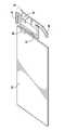
- FIG. 4is perspective view of the antenna assembly of FIG. 2 separated from the PCB.
- FIG. 5is a radiation pattern of the antenna assembly of FIG. 2 .
- FIG. 6is a radiation pattern of a three-branch antenna assembly.
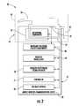
- FIG. 7is a schematic block diagram illustrating additional components that may be included in the mobile wireless communications device of FIG. 1 .
- a mobile wireless communications devicemay include a portable housing and a printed circuit board (PCB) carried by the housing and having upper and lower portions.
- the mobile wireless communications devicemay also include at least one wireless transceiver carried by the portable housing, and a satellite positioning signal receiver carried by the portable housing.
- An antenna assemblymay be carried adjacent the upper portion of the PCB.
- the antenna assemblymay include a horizontal conductor extending along the upper portion of the PCB in spaced relation therefrom.
- the horizontal conductormay be coupled to the satellite positioning receiver.
- the antenna assemblymay further include a loop conductor extending from the horizontal conductor toward the lower portion of the PCB and in spaced relation from the PCB.
- the loop conductormay be coupled to the at least one wireless transceiver.
- the mobile wireless communications devicemay further include a cellular antenna carried adjacent the lower portion of the PCB and coupled to the at least one wireless transceiver.
- the loop conductormay be configured to provide a diversity antenna for the cellular antenna, and configured to provide a Personal Communications Service (PCS) antenna, for example, and the horizontal conductor may be configured to provide a Global Positioning System (GPS) antenna, for example.
- PCSPersonal Communications Service
- GPSGlobal Positioning System
- the antenna assemblymay further include an additional conductor extending from the horizontal conductor toward the lower portion of the PCB and in spaced relation from the PCB and adjacent portions of the loop conductor.
- the antenna assemblymay be a tri-band antenna assembly, for example.
- the PCBmay include an antenna coupling area
- the mobile wireless communications devicemay further include a coupling member configured to couple the antenna assembly to the PCB at the antenna coupling area.
- the mobile wireless communications devicemay further include at least one additional component carried by the PCB beneath the antenna assembly.
- a method aspectis directed to a method for making an antenna assembly for a mobile wireless communications device including a portable housing, a printed circuit board (PCB) carried by the housing and having opposing upper and lower portions, at least one wireless transceiver carried by the portable housing, and a satellite positioning signal receiver carried by the portable housing.
- the methodmay include forming a horizontal conductor to extend along the upper portion of the PCB in spaced relation therefrom, the horizontal conductor to be coupled to the satellite positioning receiver, for example.
- the methodmay further include forming a loop conductor extending from the horizontal conductor toward the lower portion of the PCB and in spaced relation from the PCB, the loop conductor to be coupled to the at least one wireless transceiver, for example.
- a mobile wireless communications device 30illustratively includes a portable housing 31 , a printed circuit board (PCB) 32 carried by the portable housing and having an upper portion 41 and a lower portion 42 , and a wireless transceiver 33 carried by the portable housing.
- the PCB 32may be replaced by or used in conjunction with a metal chassis or other substrate.
- the PCB 32may also include a conductive layer (not shown) defining a ground plane.
- a satellite positioning signal receiver 34is also carried by the portable housing 31 .
- the satellite positioning signal receiver 34may be a Global Positioning System (GPS) satellite receiver, for example.
- GPSGlobal Positioning System
- a cellular antenna 44is illustratively carried adjacent the lower portion 42 of the PCB 32 and coupled to the wireless transceiver 33 .
- the cellular antenna 44may be carried by another portion of the PCB 32 in other embodiments.
- the cellular antenna 44may be configured to provide a Global System for Mobile Communications (GSM) antenna and a code division multiple access (CDMA) antenna, for example.
- GSMGlobal System for Mobile Communications
- CDMAcode division multiple access
- the cellular antenna 44may be configured to operate at other frequencies.
- the cellular antenna 44typically occupies a relatively large amount of space within the portable housing 31 .
- the exemplary device 30further illustratively includes a display 60 and a plurality of control keys including an “off hook” (i.e., initiate phone call) key 61 , an “on hook” (i.e., discontinue phone call) key 62 , a menu key 63 , and a return or escape key 64 . Operation of the various device components and input keys, etc., will be described further below with reference to FIG. 7 .
- the device 30further illustratively includes a tri-band antenna assembly 35 carried adjacent the upper portion 41 of the PCB 32 .
- the antenna assembly 35is carried adjacent the upper portion 41 because the cellular antenna 44 occupies the lower portion 42 of the PCB 32 and/or housing 31 .
- the antenna assembly 35includes a horizontal conductor 36 extending along the upper portion 41 of the PCB 32 in spaced relation from the upper portion of the PCB.
- the horizontal conductor 36is coupled to the satellite positioning receiver 34 .
- the horizontal conductor 36may be configured to provide a GPS antenna and may operate from 1565 MHz to 1585 MHz, for example.
- the horizontal conductor 36may be configured to operate at other frequencies in other embodiments.
- a loop conductor 37extends from the horizontal conductor 36 toward the lower portion of the PCB 32 .
- the loop conductor 37illustratively extends along a backside of the PCB 32 and is in spaced relation from the PCB.
- the loop conductor 37may be coupled to the wireless transceiver 33 .
- the loop conductor 37may be configured to provide one or both of a diversity antenna for the cellular antenna 44 that may operate between 869 MHz and 894 MHz and a Personal Communications Service (PCS) antenna that may operate between 1930 MHz and 1990 MHz, for example.
- PCSPersonal Communications Service
- the loop conductor 37may be configured to provide another antenna operating at other frequencies in other embodiments.
- the length of the horizontal conductor 36may affect the resonant frequencies of the loop conductor 37 , for example, PCS resonance.
- the antenna assembly 35advantageously cooperates with the PCB 32 to provide an improved GPS radiation pattern ( FIG. 5 ).
- the GPS radiation patternwould have a maximum radiation pointing downward or toward the ground (i.e., toward the lower portion 42 of the PCB 32 ), as illustrated in FIG. 6 .
- a substantially reduced amount, or a small amount of radiationwould be directed skyward (i.e. toward the upper portion 41 of the PCB 32 ) in contrast to the energy directed toward the lower portion 42 or ground ( FIG. 6 ).
- the antenna assembly 35is in spaced relation from the backside of the PCB 32 such that additional components 52 may be carried by the PCB beneath the antenna assembly. More particularly, the loop conductor 37 is in spaced relation from the PCB 32 such that a camera flash, a speaker, an audio jack, and other components, for example, may be between the loop conductor and the PCB or chassis.
- the spaced relation of the antenna assembly 35 and more particularly the loop conductor 37advantageously allows for improved utilization of the limited space on the PCB 32 and within the housing 31 .
- the antenna assembly 35further illustratively includes an additional conductor 45 extending from the horizontal conductor 36 toward the lower portion.
- the additional conductor 45is in spaced relation from the PCB 32 and is adjacent portions of the loop conductor 37 . In other words, the additional conductor 45 extends along a side of the PCB 32 .
- the additional conductor 45advantageously enhances the performance of the loop antenna 37 , and more particularly, the additional conductor may be configured to enhance a PCS antenna configured loop conductor.
- the antenna assembly 35 including the horizontal conductor 36 , the loop conductor 37 , and additional conductor 45may be a flexible antenna assembly.
- the conductorsmay be printed on a flexible film or substrate.
- the flexible antenna assembly including the flexible filmmay be adhered to the inside back portion of the housing 31 , for example.
- the inside back portion of the housingmay include a stanchion (not shown) for supporting the flexible antenna assembly.
- the PCB 32further includes an antenna coupling area 46 .
- the antenna assemblyfurther includes a coupling member 47 configured to couple the antenna assembly 35 to the PCB 32 at the antenna coupling area 46 .
- the coupling member 47is illustratively L-shaped, and may be, for example, a clip.
- the mobile wireless communications device 30may further include an impedance matching 48 circuit configured to match the impedance of the antenna assembly to a desired impedance.
- the impedance matching 48 circuitmay include lumped components in three different frequency bands, for example.
- the impedance matching circuit 48matches the antenna assembly impedance to 50 ohms, for example.
- a controller 51 or processormay also be carried by the PCB 32 .
- the controller 51may cooperate with the other components, for example, the antenna assembly 35 , the satellite positioning signal receiver 34 , the cellular antenna 44 , and the wireless transceiver 33 to coordinate and control operations of the mobile wireless communications device 30 .
- Operationsmay include mobile voice and data operations, including email and Internet data.
- a method aspectis directed to a method of making an antenna assembly 35 for a mobile wireless communications device 30 .
- the mobile wireless communications device 30includes a portable housing 31 , and a PCB 32 carried by portable housing and having opposing upper and lower portions 41 , 42 .
- the mobile wireless communications device 30also includes a wireless transceiver 33 carried by the portable housing 31 , and a satellite positioning signal receiver 34 also carried by the portable housing.
- the methodincludes forming a horizontal conductor 36 to extend along the upper portion 41 of the PCB 32 in spaced relation therefrom.
- the horizontal conductor 36is to be coupled to the satellite positioning receiver 34 .
- the methodalso includes forming a loop conductor 37 extending from the horizontal conductor 36 toward the lower portion 42 of the PCB 32 and in spaced relation from the PCB.
- the loop conductor 37is to be coupled to the wireless transceiver 33 .
- the device 1000illustratively includes a housing 1200 , a keypad 1400 and an output device 1600 .
- the output device shownis a display 1600 , which may comprise a full graphic LCD.
- display 1600may comprise a touch-sensitive input and output device.
- a processing device 1800is contained within the housing 1200 and is coupled between the keypad 1400 and the display 1600 .
- the processing device 1800controls the operation of the display 1600 , as well as the overall operation of the mobile device 1000 , in response to actuation of keys on the keypad 1400 by the user.
- keypad 1400may comprise a physical keypad or a virtual keypad (e.g., using a touch-sensitive interface) or both.
- the housing 1200may be elongated vertically, or may take on other sizes and shapes (including clamshell housing structures, for example).
- the keypad 1400may include a mode selection key, or other hardware or software for switching between text entry and telephony entry.
- FIG. 7In addition to the processing device 1800 , other parts of the mobile device 1000 are shown schematically in FIG. 7 . These include a communications subsystem 1001 ; a short-range communications subsystem 1020 ; the keypad 1400 and the display 1600 , along with other input/output devices 1060 , 1080 , 1100 and 1120 ; as well as memory devices 1160 , 1180 and various other device subsystems 1201 .
- the mobile device 1000may comprise a two-way RF communications device having voice and data communications capabilities. In addition, the mobile device 1000 may have the capability to communicate with other computer systems via the Internet.
- Operating system software executed by the processing device 1800may be stored in a persistent store, such as the flash memory 1160 , but may be stored in other types of memory devices, such as a read only memory (ROM) or similar storage element.
- system software, specific device applications, or parts thereofmay be temporarily loaded into a volatile store, such as the random access memory (RAM) 1180 .
- Communications signals received by the mobile devicemay also be stored in the RAM 1180 .
- the processing device 1800in addition to its operating system functions, enables execution of software applications or modules 1300 A- 1300 N on the device 1000 , such as software modules for performing various steps or operations.
- a predetermined set of applications that control basic device operations, such as data and voice communications 1300 A and 1300 B,may be installed on the device 1000 during manufacture.
- a personal information manager (PIM) applicationmay be installed during manufacture.
- the PIMmay be capable of organizing and managing data items, such as e-mail, calendar events, voice mails, appointments, and task items.
- the PIM applicationmay also be capable of sending and receiving data items via a wireless network 1401 .
- the PIM data itemsmay be seamlessly integrated, synchronized and updated via the wireless network 1401 with the device user's corresponding data items stored or associated with a host computer system.
- the communications subsystem 1001includes a receiver 1500 , a transmitter 1520 , and one or more antennas 1540 and 1560 .
- the communications subsystem 1001also includes a processing module, such as a digital signal processor (DSP) 1580 , and local oscillators (Las) 1601 .
- DSPdigital signal processor
- Laslocal oscillators
- a mobile device 1000may include a communications subsystem 1001 designed to operate with the MobitexTM, Data TACTM or General Packet Radio Service (GPRS) mobile data communications networks, and also designed to operate with any of a variety of voice communications networks, such as AMPS, TDMA, CDMA, WCDMA, PCS, GSM, EDGE, etc. Other types of data and voice networks, both separate and integrated, may also be utilized with the mobile device 1000 .
- the mobile device 1000may also be compliant with other communications standards such as GSM, 3G, UMTS, 4G, etc.
- Network access requirementsvary depending upon the type of communication system. For example, in the Mobitex and DataTAC networks, mobile devices are registered on the network using a unique personal identification number or PIN associated with each device. In GPRS networks, however, network access is associated with a subscriber or user of a device. A GPRS device therefore utilizes a subscriber identity module, commonly referred to as a SIM card, in order to operate on a GPRS network.
- SIM cardsubscriber identity module
- the mobile device 1000may send and receive communications signals over the communication network 1401 .
- Signals received from the communications network 1401 by the antenna 1540are routed to the receiver 1500 , which provides for signal amplification, frequency down conversion, filtering, channel selection, etc., and may also provide analog to digital conversion. Analog-to-digital conversion of the received signal allows the DSP 1580 to perform more complex communications functions, such as demodulation and decoding.
- signals to be transmitted to the network 1401are processed (e.g. modulated and encoded) by the DSP 1580 and are then provided to the transmitter 1520 for digital to analog conversion, frequency up conversion, filtering, amplification and transmission to the communication network 1401 (or networks) via the antenna 1560 .
- the DSP 1580provides for control of the receiver 1500 and the transmitter 1520 .
- gains applied to communications signals in the receiver 1500 and transmitter 1520may be adaptively controlled through automatic gain control algorithms implemented in the DSP 1580 .
- a received signalsuch as a text message or web page download
- the communications subsystem 1001is input to the processing device 1800 .
- the received signalis then further processed by the processing device 1800 for an output to the display 1600 , or alternatively to some other auxiliary I/O device 1060 .
- a device usermay also compose data items, such as e-mail messages, using the keypad 1400 and/or some other auxiliary I/O device 1060 , such as a touchpad, a rocker switch, a thumb-wheel, or some other type of input device.
- the composed data itemsmay then be transmitted over the communications network 1401 via the communications subsystem 1001 .
- a voice communications modeIn a voice communications mode, overall operation of the device is substantially similar to the data communications mode, except that received signals are output to a speaker 1100 , and signals for transmission are generated by a microphone 1120 .
- Alternative voice or audio I/O subsystemssuch as a voice message recording subsystem, may also be implemented on the device 1000 .
- the display 1600may also be utilized in voice communications mode, for example to display the identity of a calling party, the duration of a voice call, or other voice call related information.
- the short-range communications subsystemenables communication between the mobile device 1000 and other proximate systems or devices, which need not necessarily be similar devices.
- the short-range communications subsystemmay include an infrared device and associated circuits and components, or a BluetoothTM communications module to provide for communication with similarly-enabled systems and devices.
Landscapes
- Engineering & Computer Science (AREA)
- Computer Networks & Wireless Communication (AREA)
- Support Of Aerials (AREA)
- Telephone Set Structure (AREA)
- Manufacturing & Machinery (AREA)
- Mobile Radio Communication Systems (AREA)
Abstract
Description
Claims (21)
Priority Applications (2)
| Application Number | Priority Date | Filing Date | Title |
|---|---|---|---|
| US12/945,200US8644894B2 (en) | 2010-03-12 | 2010-11-12 | Mobile wireless device with multi-band antenna and related methods |
| US14/134,994US9698468B2 (en) | 2010-03-12 | 2013-12-19 | Mobile wireless device with multi-band antenna and related methods |
Applications Claiming Priority (2)
| Application Number | Priority Date | Filing Date | Title |
|---|---|---|---|
| US31333710P | 2010-03-12 | 2010-03-12 | |
| US12/945,200US8644894B2 (en) | 2010-03-12 | 2010-11-12 | Mobile wireless device with multi-band antenna and related methods |
Related Child Applications (1)
| Application Number | Title | Priority Date | Filing Date |
|---|---|---|---|
| US14/134,994ContinuationUS9698468B2 (en) | 2010-03-12 | 2013-12-19 | Mobile wireless device with multi-band antenna and related methods |
Publications (2)
| Publication Number | Publication Date |
|---|---|
| US20110223873A1 US20110223873A1 (en) | 2011-09-15 |
| US8644894B2true US8644894B2 (en) | 2014-02-04 |
Family
ID=44219142
Family Applications (2)
| Application Number | Title | Priority Date | Filing Date |
|---|---|---|---|
| US12/945,200Active2032-04-26US8644894B2 (en) | 2010-03-12 | 2010-11-12 | Mobile wireless device with multi-band antenna and related methods |
| US14/134,994Active2031-11-01US9698468B2 (en) | 2010-03-12 | 2013-12-19 | Mobile wireless device with multi-band antenna and related methods |
Family Applications After (1)
| Application Number | Title | Priority Date | Filing Date |
|---|---|---|---|
| US14/134,994Active2031-11-01US9698468B2 (en) | 2010-03-12 | 2013-12-19 | Mobile wireless device with multi-band antenna and related methods |
Country Status (3)
| Country | Link |
|---|---|
| US (2) | US8644894B2 (en) |
| EP (1) | EP2365581B1 (en) |
| CA (1) | CA2733853C (en) |
Cited By (1)
| Publication number | Priority date | Publication date | Assignee | Title |
|---|---|---|---|---|
| US20140104120A1 (en)* | 2010-03-12 | 2014-04-17 | Blackberry Limited | Mobile wireless device with multi-band antenna and related methods |
Families Citing this family (12)
| Publication number | Priority date | Publication date | Assignee | Title |
|---|---|---|---|---|
| ES2640983T3 (en) | 2011-05-17 | 2017-11-07 | Koninklijke Philips N.V. | Neck cord incorporating extensions of the ground plane |
| US11769949B2 (en)* | 2016-08-29 | 2023-09-26 | Silicon Laboratories Inc. | Apparatus with partitioned radio frequency antenna and matching network and associated methods |
| US11749893B2 (en) | 2016-08-29 | 2023-09-05 | Silicon Laboratories Inc. | Apparatus for antenna impedance-matching and associated methods |
| US11894622B2 (en) | 2016-08-29 | 2024-02-06 | Silicon Laboratories Inc. | Antenna structure with double-slotted loop and associated methods |
| US11764473B2 (en) | 2016-08-29 | 2023-09-19 | Silicon Laboratories Inc. | Apparatus with partitioned radio frequency antenna and matching network and associated methods |
| US11764749B2 (en) | 2016-08-29 | 2023-09-19 | Silicon Laboratories Inc. | Apparatus with partitioned radio frequency antenna and matching network and associated methods |
| JP6825429B2 (en)* | 2017-03-09 | 2021-02-03 | 富士通株式会社 | Multi-band antenna and wireless communication device |
| US11894621B2 (en) | 2017-12-18 | 2024-02-06 | Silicon Laboratories Inc. | Radio-frequency apparatus with multi-band balun with improved performance and associated methods |
| US11894826B2 (en) | 2017-12-18 | 2024-02-06 | Silicon Laboratories Inc. | Radio-frequency apparatus with multi-band balun and associated methods |
| US11750167B2 (en) | 2017-11-27 | 2023-09-05 | Silicon Laboratories Inc. | Apparatus for radio-frequency matching networks and associated methods |
| US11916514B2 (en) | 2017-11-27 | 2024-02-27 | Silicon Laboratories Inc. | Radio-frequency apparatus with multi-band wideband balun and associated methods |
| US11862872B2 (en) | 2021-09-30 | 2024-01-02 | Silicon Laboratories Inc. | Apparatus for antenna optimization and associated methods |
Citations (14)
| Publication number | Priority date | Publication date | Assignee | Title |
|---|---|---|---|---|
| US5083136A (en)* | 1989-11-16 | 1992-01-21 | Wells Donald H | Transmission line coupling device with closed impedance matching loop |
| US5198826A (en)* | 1989-09-22 | 1993-03-30 | Nippon Sheet Glass Co., Ltd. | Wide-band loop antenna with outer and inner loop conductors |
| US5748512A (en) | 1995-02-28 | 1998-05-05 | Microsoft Corporation | Adjusting keyboard |
| US6160354A (en) | 1999-07-22 | 2000-12-12 | 3Com Corporation | LED matrix current control system |
| WO2003107168A1 (en) | 2002-06-14 | 2003-12-24 | Nokia Corporation | Electronic device and method of managing its keyboard |
| US6980173B2 (en)* | 2003-07-24 | 2005-12-27 | Research In Motion Limited | Floating conductor pad for antenna performance stabilization and noise reduction |
| US7068230B2 (en)* | 2004-06-02 | 2006-06-27 | Research In Motion Limited | Mobile wireless communications device comprising multi-frequency band antenna and related methods |
| US20060186986A1 (en) | 2005-02-23 | 2006-08-24 | Ma Jun T | Method of monitoring and controlling devices with instant messaging |
| US7113135B2 (en) | 2004-06-08 | 2006-09-26 | Skycross, Inc. | Tri-band antenna for digital multimedia broadcast (DMB) applications |
| US7205942B2 (en) | 2005-07-06 | 2007-04-17 | Nokia Corporation | Multi-band antenna arrangement |
| US20070171158A1 (en) | 2006-01-22 | 2007-07-26 | Shalabh Kumar | Low power led-based marquee systems |
| US20070247429A1 (en) | 2006-04-25 | 2007-10-25 | Apple Computer, Inc. | Keystroke tactility arrangement on a smooth touch surface |
| US7310344B1 (en) | 2001-12-28 | 2007-12-18 | Cisco Technology, Inc. | Method and system for an instant messenger home automation system interface using a home router |
| US7679569B2 (en)* | 2006-04-10 | 2010-03-16 | Hitachi Metals, Ltd. | Antenna device and multi-band type wireless communication apparatus using same |
Family Cites Families (13)
| Publication number | Priority date | Publication date | Assignee | Title |
|---|---|---|---|---|
| US171158A (en)* | 1875-12-14 | Improvement in swinging gates | ||
| US186986A (en)* | 1877-02-06 | Improvement in the manufacture of hollow glassware | ||
| US247429A (en)* | 1881-09-20 | Means for elevating and depressing propellers | ||
| US6618019B1 (en)* | 2002-05-24 | 2003-09-09 | Motorola, Inc. | Stubby loop antenna with common feed point |
| TW549620U (en)* | 2002-11-13 | 2003-08-21 | Hon Hai Prec Ind Co Ltd | Multi-band antenna |
| JP3843429B2 (en)* | 2003-01-23 | 2006-11-08 | ソニーケミカル&インフォメーションデバイス株式会社 | Electronic equipment and printed circuit board mounted with antenna |
| US6909402B2 (en)* | 2003-06-11 | 2005-06-21 | Sony Ericsson Mobile Communications Ab | Looped multi-branch planar antennas having multiple resonant frequency bands and wireless terminals incorporating the same |
| US7592958B2 (en)* | 2003-10-22 | 2009-09-22 | Sony Ericsson Mobile Communications, Ab | Multi-band antennas and radio apparatus incorporating the same |
| TWI237419B (en)* | 2003-11-13 | 2005-08-01 | Hitachi Ltd | Antenna, method for manufacturing the same and portable radio terminal employing it |
| JP2007123982A (en)* | 2005-10-25 | 2007-05-17 | Sony Ericsson Mobilecommunications Japan Inc | Multiband compatible antenna system and communication terminal |
| JP4231867B2 (en)* | 2005-11-18 | 2009-03-04 | 株式会社東芝 | Wireless device and electronic device |
| TW200933985A (en)* | 2008-01-16 | 2009-08-01 | Quanta Comp Inc | Dual frequency antenna |
| US8644894B2 (en)* | 2010-03-12 | 2014-02-04 | Blackberry Limited | Mobile wireless device with multi-band antenna and related methods |
- 2010
- 2010-11-12USUS12/945,200patent/US8644894B2/enactiveActive
- 2010-11-12EPEP10191093.3Apatent/EP2365581B1/enactiveActive
- 2011
- 2011-03-11CACA2733853Apatent/CA2733853C/enactiveActive
- 2013
- 2013-12-19USUS14/134,994patent/US9698468B2/enactiveActive
Patent Citations (14)
| Publication number | Priority date | Publication date | Assignee | Title |
|---|---|---|---|---|
| US5198826A (en)* | 1989-09-22 | 1993-03-30 | Nippon Sheet Glass Co., Ltd. | Wide-band loop antenna with outer and inner loop conductors |
| US5083136A (en)* | 1989-11-16 | 1992-01-21 | Wells Donald H | Transmission line coupling device with closed impedance matching loop |
| US5748512A (en) | 1995-02-28 | 1998-05-05 | Microsoft Corporation | Adjusting keyboard |
| US6160354A (en) | 1999-07-22 | 2000-12-12 | 3Com Corporation | LED matrix current control system |
| US7310344B1 (en) | 2001-12-28 | 2007-12-18 | Cisco Technology, Inc. | Method and system for an instant messenger home automation system interface using a home router |
| WO2003107168A1 (en) | 2002-06-14 | 2003-12-24 | Nokia Corporation | Electronic device and method of managing its keyboard |
| US6980173B2 (en)* | 2003-07-24 | 2005-12-27 | Research In Motion Limited | Floating conductor pad for antenna performance stabilization and noise reduction |
| US7068230B2 (en)* | 2004-06-02 | 2006-06-27 | Research In Motion Limited | Mobile wireless communications device comprising multi-frequency band antenna and related methods |
| US7113135B2 (en) | 2004-06-08 | 2006-09-26 | Skycross, Inc. | Tri-band antenna for digital multimedia broadcast (DMB) applications |
| US20060186986A1 (en) | 2005-02-23 | 2006-08-24 | Ma Jun T | Method of monitoring and controlling devices with instant messaging |
| US7205942B2 (en) | 2005-07-06 | 2007-04-17 | Nokia Corporation | Multi-band antenna arrangement |
| US20070171158A1 (en) | 2006-01-22 | 2007-07-26 | Shalabh Kumar | Low power led-based marquee systems |
| US7679569B2 (en)* | 2006-04-10 | 2010-03-16 | Hitachi Metals, Ltd. | Antenna device and multi-band type wireless communication apparatus using same |
| US20070247429A1 (en) | 2006-04-25 | 2007-10-25 | Apple Computer, Inc. | Keystroke tactility arrangement on a smooth touch surface |
Non-Patent Citations (3)
| Title |
|---|
| Cheng et al., Temporal Vision-Guided Energy Minimization for Portable Displays, Oct. 2006, pp. 1-6. |
| Himberg et al., On-Line Personalization of a Touch Screen Based Keyboard, Jan. 2003, pp. 1-8. |
| Jung et al., Internal Folded Loop Antenna with Tuning Notches for GSM/GPS/DCS/PCS Mobile Handset Applications, Aug. 2006, pp. 1501-1504. |
Cited By (2)
| Publication number | Priority date | Publication date | Assignee | Title |
|---|---|---|---|---|
| US20140104120A1 (en)* | 2010-03-12 | 2014-04-17 | Blackberry Limited | Mobile wireless device with multi-band antenna and related methods |
| US9698468B2 (en)* | 2010-03-12 | 2017-07-04 | Blackberry Limited | Mobile wireless device with multi-band antenna and related methods |
Also Published As
| Publication number | Publication date |
|---|---|
| CA2733853A1 (en) | 2011-09-12 |
| EP2365581B1 (en) | 2017-08-23 |
| US20110223873A1 (en) | 2011-09-15 |
| CA2733853C (en) | 2014-09-16 |
| EP2365581A2 (en) | 2011-09-14 |
| US9698468B2 (en) | 2017-07-04 |
| EP2365581A3 (en) | 2014-03-05 |
| US20140104120A1 (en) | 2014-04-17 |
Similar Documents
| Publication | Publication Date | Title |
|---|---|---|
| US9698468B2 (en) | Mobile wireless device with multi-band antenna and related methods | |
| US9337528B2 (en) | Mobile wireless communications device including electrically conductive portable housing sections defining an antenna | |
| US8497806B2 (en) | Mobile wireless device with multi-band loop antenna with arms defining a slotted opening and related methods | |
| US8326385B2 (en) | Mobile wireless communications device with proximity based transmitted power control and related methods | |
| US8253635B2 (en) | Mobile wireless communications device including a ground patch providing specific absorption rate (SAR) reduction and related methods | |
| US20090219216A1 (en) | Mobile wireless communications device with selective load switching for antennas and related methods | |
| EP2509229A1 (en) | Mobile wireless communications device with proximity based transmitted power control and related methods | |
| EP2621017A1 (en) | Mobile wireless communications device including electrically conductive portable housing sections defining an antenna | |
| US8952852B2 (en) | Mobile wireless communications device including antenna assembly having shorted feed points and inductor-capacitor circuit and related methods | |
| US20120299784A1 (en) | Mobile wireless communications device including an antenna having a shorting plate | |
| US8761847B2 (en) | Mobile wireless communications device having an antenna assembly with corner coupled rectangular base conductor portions and related methods | |
| US8933847B2 (en) | Mobile wireless communications device having antenna assembly with electrically conductive base enclosing an elongate slot and associated methods | |
| CA2770798C (en) | Mobile wireless communications device including antenna assembly having shorted feed points and inductor-capacitor circuit and related methods | |
| US8797217B2 (en) | Mobile wireless communications device including antenna assembly having spaced apart parallel conductor arms and related methods | |
| EP1981119B1 (en) | Mobile wireless communications device including a ground patch providing specific absorption rate (SAR) reduction and related methods |
Legal Events
| Date | Code | Title | Description |
|---|---|---|---|
| AS | Assignment | Owner name:RESEARCH IN MOTION LIMITED, CANADA Free format text:ASSIGNMENT OF ASSIGNORS INTEREST;ASSIGNOR:QIU, MEIDE;REEL/FRAME:025512/0887 Effective date:20101105 | |
| AS | Assignment | Owner name:BLACKBERRY LIMITED, ONTARIO Free format text:CHANGE OF NAME;ASSIGNOR:RESEARCH IN MOTION LIMITED;REEL/FRAME:031896/0305 Effective date:20130709 | |
| STCF | Information on status: patent grant | Free format text:PATENTED CASE | |
| FPAY | Fee payment | Year of fee payment:4 | |
| MAFP | Maintenance fee payment | Free format text:PAYMENT OF MAINTENANCE FEE, 8TH YEAR, LARGE ENTITY (ORIGINAL EVENT CODE: M1552); ENTITY STATUS OF PATENT OWNER: LARGE ENTITY Year of fee payment:8 | |
| AS | Assignment | Owner name:MALIKIE INNOVATIONS LIMITED, IRELAND Free format text:ASSIGNMENT OF ASSIGNORS INTEREST;ASSIGNOR:BLACKBERRY LIMITED;REEL/FRAME:064104/0103 Effective date:20230511 | |
| AS | Assignment | Owner name:MALIKIE INNOVATIONS LIMITED, IRELAND Free format text:NUNC PRO TUNC ASSIGNMENT;ASSIGNOR:BLACKBERRY LIMITED;REEL/FRAME:064270/0001 Effective date:20230511 | |
| MAFP | Maintenance fee payment | Free format text:PAYMENT OF MAINTENANCE FEE, 12TH YEAR, LARGE ENTITY (ORIGINAL EVENT CODE: M1553); ENTITY STATUS OF PATENT OWNER: LARGE ENTITY Year of fee payment:12 |