US8644557B2 - Method and apparatus for estimating position of moving vehicle such as mobile robot - Google Patents
Method and apparatus for estimating position of moving vehicle such as mobile robotDownload PDFInfo
- Publication number
- US8644557B2 US8644557B2US13/296,989US201113296989AUS8644557B2US 8644557 B2US8644557 B2US 8644557B2US 201113296989 AUS201113296989 AUS 201113296989AUS 8644557 B2US8644557 B2US 8644557B2
- Authority
- US
- United States
- Prior art keywords
- motion
- noise
- unit
- image frame
- moving vehicle
- Prior art date
- Legal status (The legal status is an assumption and is not a legal conclusion. Google has not performed a legal analysis and makes no representation as to the accuracy of the status listed.)
- Active, expires
Links
Images


Classifications
- G—PHYSICS
- G06—COMPUTING OR CALCULATING; COUNTING
- G06V—IMAGE OR VIDEO RECOGNITION OR UNDERSTANDING
- G06V20/00—Scenes; Scene-specific elements
- G06V20/10—Terrestrial scenes
- B—PERFORMING OPERATIONS; TRANSPORTING
- B25—HAND TOOLS; PORTABLE POWER-DRIVEN TOOLS; MANIPULATORS
- B25J—MANIPULATORS; CHAMBERS PROVIDED WITH MANIPULATION DEVICES
- B25J13/00—Controls for manipulators
- B—PERFORMING OPERATIONS; TRANSPORTING
- B25—HAND TOOLS; PORTABLE POWER-DRIVEN TOOLS; MANIPULATORS
- B25J—MANIPULATORS; CHAMBERS PROVIDED WITH MANIPULATION DEVICES
- B25J19/00—Accessories fitted to manipulators, e.g. for monitoring, for viewing; Safety devices combined with or specially adapted for use in connection with manipulators
- B25J19/02—Sensing devices
- B25J19/04—Viewing devices
- G—PHYSICS
- G06—COMPUTING OR CALCULATING; COUNTING
- G06T—IMAGE DATA PROCESSING OR GENERATION, IN GENERAL
- G06T7/00—Image analysis
- G06T7/70—Determining position or orientation of objects or cameras
- G06T7/77—Determining position or orientation of objects or cameras using statistical methods
- G—PHYSICS
- G06—COMPUTING OR CALCULATING; COUNTING
- G06T—IMAGE DATA PROCESSING OR GENERATION, IN GENERAL
- G06T2207/00—Indexing scheme for image analysis or image enhancement
- G06T2207/10—Image acquisition modality
- G06T2207/10016—Video; Image sequence
- G—PHYSICS
- G06—COMPUTING OR CALCULATING; COUNTING
- G06T—IMAGE DATA PROCESSING OR GENERATION, IN GENERAL
- G06T2207/00—Indexing scheme for image analysis or image enhancement
- G06T2207/30—Subject of image; Context of image processing
- G06T2207/30244—Camera pose
- G—PHYSICS
- G06—COMPUTING OR CALCULATING; COUNTING
- G06T—IMAGE DATA PROCESSING OR GENERATION, IN GENERAL
- G06T2207/00—Indexing scheme for image analysis or image enhancement
- G06T2207/30—Subject of image; Context of image processing
- G06T2207/30248—Vehicle exterior or interior
- G06T2207/30252—Vehicle exterior; Vicinity of vehicle
Definitions
- Apparatuses and methods consistent with exemplary embodimentsrelate to estimating a position of a moving vehicle such as a mobile robot.
- Robotsoriginally refer to automatic dolls having hands and other parts operating like a human and also having a human shape made by assembling mechanical apparatuses therein. Recently, the word “robot” signifies any automated equipment performing a job by itself regardless of its shape. In particular, mobile robots are widely adopted because they can perform an operation on behalf of a human under an extreme environment or in a dangerous place. Also, home mobile robots, such as cleaning robots, for helping housework while moving around in a house by itself, have been widely distributed.
- the robotIn order for a robot to automatically perform various jobs, the robot is capable of moving by itself. To address a robot's self moving matter, localization for recognizing its own position is essential for performing a job by itself while moving around.
- One of localization technologiesis a simultaneous localization and mapping (SLAM).
- the SLAM of a robotis a method of detecting surrounding environment information, processing obtained information, making a map corresponding to a space for performing a job, and tracking its own absolute position.
- GPSglobal positioning system
- LIDARlight detection and ranging
- a cameraa camera
- GPSglobal positioning system
- LIDARlight detection and ranging
- a cameraa camera
- the GPSis often erroneous and works properly only in an outdoor environment.
- the LIDARis known to be accurate but easily fails to track the position of a robot due to non-reflection of light when used outdoors.
- One or more exemplary embodimentsprovide a method and apparatus for estimating a position of a moving vehicle such as mobile robot by which the position of the moving vehicle may be effectively estimated at a low cost using an image obtained from a single camera.
- an apparatus of estimating a position of a moving vehiclemay include a feature point matching unit which generates vectors connecting feature points of a previous image frame and feature points of a current image frame, corresponding to the feature points of the previous image frame, and determines spatial correlations between the feature points of the current image frame, a clustering unit which configures at least one motion cluster by grouping at least one vector among the vectors based on the spatial correlations in a feature space, and a noise removal unit which removes noise from each motion cluster of the at least one motion cluster, wherein the position of the moving vehicle is estimated based on the at least one motion cluster.
- the feature point matching unitmay include a feature point extraction unit which tracks the feature points of the current image, and generates the vectors connecting the corresponding feature points between the two image frames by detecting optical flow of each pixel, and a correlation determination unit which determines the spatial correlations.
- a method of estimating a position of a moving vehiclemay include generating vectors connecting feature points of a previous image frame and feature points of a current image frame corresponding to the feature points of the previous image frame, determining spatial correlations between the feature points of the current image frame, configuring at least one motion cluster by grouping the vectors based on the spatial correlations in a feature space, and removing noise from each motion cluster of the at least one motion cluster.
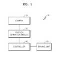
- FIG. 1is a block diagram schematically illustrating an internal structure of a robot according to an exemplary embodiment
- FIG. 2is block diagram schematically illustrating an internal structure of an apparatus for estimating the position of a robot according to an exemplary embodiment
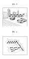
- FIG. 3illustrates an example in which vectors are indicated according to feature point matching performed on input image frames according to an exemplary embodiment
- FIG. 4illustrates an example in which motion clusters of an input image frame are configured according to an exemplary embodiment
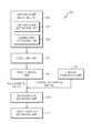
- FIG. 5is a flowchart for explaining a method of estimating the position of a robot according to an exemplary embodiment
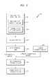
- FIG. 6is a flowchart for explaining a method of determining a fundamental matrix for estimating the position of a robot according to an exemplary embodiment.
- FIG. 1is a block diagram schematically illustrating an internal structure of a robot 10 according to an exemplary embodiment.
- the robot 10according to the present exemplary embodiment includes a camera 20 , a position estimation module 30 , a controller 40 , and a driving unit 50 .
- the robot 10may be a mobile robot for performing a particular job while moving around in a predetermined area.
- the movement and job performance of the robot 10are automatically executed.
- the robot 10needs to accurately recognize its own position.
- the camera 20obtains an image of a scene that the robot 10 sees directly ahead in a moving direction.
- the direction in which a scene is to be obtainedmay be changed by rotating the robot 10 or by horizontally rotating the camera 20 around the center of the robot 10 .
- the position estimation module 30estimates a position of the robot 10 . Since the robot 10 is equipped with the camera 20 , position estimation by the camera 20 and position estimation by the robot 10 may be interchangeably referred to in the following description to describe the same position estimation.
- the position estimation module 30analyzes the position of the robot 10 or the camera 20 based on a feature point matching algorithm of two sequential video frames, without using GPS or odometry information. Various algorithms may be used for processing information of the position estimation module 30 .
- a simultaneous localization and mapping (SLAM) technologymay be typically used therefor.
- the SLAMis a method of estimating an absolute position in a space using a relative position value of the robot 10 and a surrounding environment.
- the position estimation module 30extracts a feature point from a current image frame and a feature point from a previous image frame, and matches the feature points extracted from the two image frames. During feature point matching, the position estimation module 30 extracts and tracks the feature points using a Kanade-Lucas-Tomasi (KLT) tracker and a Harris corner detector, and sets correlations between the feature points by applying a Delaunay triangulation technique, thereby obtaining spatial information.
- KLTKanade-Lucas-Tomasi
- the position estimation module 30clusters vectors generated by the feature point matching using the spatial information among the feature points.
- the position estimation module 30may perform clustering by applying a Markov random field (MRF) optimization algorithm to a feature space.
- MRFMarkov random field
- the position estimation module 30removes noise by excluding an outlier of each cluster, and determines a fundamental matrix for each cluster.
- the position estimation module 30may remove the outlier by applying random sample consensus (RANSAC) to each cluster.
- RBSACrandom sample consensus
- the controller 40controls the operations of the position estimation module 30 and the driving unit 50 .
- the driving unit 50controls the movement of the robot 10 and provides power to the robot 10 .
- the driving unit 50includes arms, legs, joints or wheels, and may be configured by a mechanism including a direction control apparatus, a drive motor, gears, etc. to move the robot 10 .
- FIG. 2is block diagram schematically illustrating an internal structure of an apparatus 300 for estimating the position of a robot, according to an exemplary embodiment.
- the apparatus 300may represent the position estimation module 30 in FIG. 1 .
- the robot position estimation apparatus 300includes a feature point matching unit 301 , a clustering unit 303 , a noise removal unit 305 , a camera calibration unit 307 , a three-dimensional (3D) coordinate estimation unit 309 , and a robot position estimation unit 311 .
- the feature point matching unit 301extracts a feature point from a current image frame and a feature point from a previous image frame input by the camera 20 , and matches the feature points extracted from the two image frames.
- the matchingincludes an operation of identifying corresponding points between the current image frame and the previous image frame.
- a related art fundamental matrix determination algorithm using feature point matchingoperates only in a static environment due to its own characteristic. For example, when an epipolar constraint condition is use, at least seven matched feature points are needed to determine a fundamental matrix. These matched two feature points that are corresponding points or correspondences are located on epipolar lines of different cameras. Thus, assuming that the corresponding points are points extracted from a mobile object, the corresponding points may not be located on an epipolar line.
- the feature point matching unit 301 of the present exemplary embodimentperforms accurate feature point matching in a dynamic environment using a matching type of a feature point, that is, a context of a moving history.
- the feature point matching unit 301includes a feature point extraction unit 321 and a correlation determination unit 323 .
- the feature point extraction unit 321extracts feature points from a current image frame and corresponding feature points from a previous image frame. That is, the feature point extraction unit 321 extracts feature points of a current image frame corresponding to those of a previous image frame, and generates vectors connecting the corresponding feature points between the two image frames by detecting optical flow of each pixel.
- the optical flowsignifies a movement, which is represented by a set of vectors, appearing on two input image frames, photographed by a camera, at different time points.
- FIG. 3illustrates an example in which vectors are indicated according to feature point matching performed on input image frames according to an exemplary embodiment.
- the feature point extraction unit 321may extract feature points by using the KLT tracker and the Harris corner detector.
- the present inventive conceptis not limited thereto, and a variety of methods for extracting a feature point may be employed therefor.
- the correlation determination unit 323determines spatial correlations with respect to feature points of an image frame.
- the points that are spatially adjacent to each otherare highly likely to belong to the same object and have the same movement.
- the correlation determination unit 323may indicate a correlation between feature points by triangularizing the feature points on a two-dimensional (2D) plane using, for example, the Delaunay triangulation technique.
- 2Dtwo-dimensional
- the inventive conceptis not limited thereto, and other triangulation techniques capable of defining spatial correlations may be used therefor.
- the clustering unit 303performs spatially coherent motion clustering to group static backgrounds and a plurality of movements.
- the clustering unit 303groups vectors based on spatial correlations considering positions of the vectors in the feature space with parameters of vectors' movement directions, thereby configuring at least one motion cluster.
- FIG. 4illustrates an example in which motion clusters a, b, and c of an input image frame are configured according to an exemplary embodiment.
- the clustering unit 303may perform motion clustering by applying the MRF optimization algorithm to a lattice formed in a triangle by the Delaunay triangulation technique.
- a graph-cut techniquemay be used to MRF optimization.
- the inventive conceptis not limited thereto, and a variety of techniques capable of performing clustering may be used therefor.
- the noise removal unit 305configures at least one motion cluster removed of noise by removing an outlier from each motion cluster.
- An outlier that is one of the vectorshas a large error in a motion cluster, that is, a vector having a remarkably low consistency.
- the outlieris noise including a sensor outlier generated by sensor noise and a motion outlier generated by a mobile object.
- the noise removal unit 305determines a fundamental matrix for each motion cluster removed of noise.
- outliersmay be removed by applying RANSAC to each motion cluster.
- the camera calibration unit 307determines a camera calibration matrix by obtaining camera internal parameters.
- the 3D coordinate estimation unit 309determines 3D coordinates of feature points based on camera external parameters such as rotation and translation of the camera 20 for each motion cluster.
- the 3D coordinate estimation unit 309determines an essential matrix from the fundamental matrix and the camera calibration matrix.
- the 3D coordinate estimation unit 309extracts rotation and translation components of the camera 20 from the determined essential matrix.
- the 3D coordinate estimation unit 309determines a camera matrix from the essential matrix and determines 3D coordinates of the camera 20 from the camera matrix.
- the robot position estimation unit 311estimates a position of the robot 10 based on the 3D coordinates of the camera 20 determined for each motion cluster.
- the robot position estimation unit 311estimates the position of the robot 10 by tracking a relative position of the camera 20 determined for each motion cluster on an assumption of a constant speed. In doing so, an extended Kalman filter algorithm may be used.
- FIG. 5is a flowchart for explaining a method of estimating a position of a robot according to an exemplary embodiment, in reference to FIGS. 1 and 2 .
- the robot 10extracts feature points from input image frames and matches the feature points extracted from a current image frame and a previous image frame (S 501 ).
- the robot 10may extract and track the feature points using the KLT tracker and the Harris corner detector, and set correlations between the feature points by applying the Delaunay triangulation technique, thereby obtaining spatial information.
- the robot 10clusters vectors generated by the feature point matching, using spatial information between the feature points (S 503 ).
- the robot 10may perform clustering by applying the MRF optimization algorithm to a feature space.
- the robot 10removes noise by excluding an outlier of each cluster (S 505 ).
- the robot 10may remove the outlier by applying the RANSAC to each cluster.
- the robot 10determines an essential matrix based on a fundamental matrix and a camera calibration matrix determined on each cluster removed of noise (S 507 ).
- the rotation and translation components of the camera 20are extracted from the essential matrix.
- 3D coordinates of the camera 20may be determined.
- the 3D coordinatesinclude rotation and translation parameters.
- the robot 10estimates its position based on the 3D coordinates of the camera 20 determined for each cluster (S 509 ).
- FIG. 6is a flowchart for explaining a method of determining a fundamental matrix for estimating the position of a robot according to an exemplary embodiment, in reference to FIGS. 1 , 2 and 5 .
- the position estimation module 30 of the robot 10extracts feature points from input image frames (S 601 ).
- the position estimation module 30tracks feature points of a current image frame corresponding to feature points of a previous image frame (S 603 ).
- the position estimation module 30detects optical flow of each pixel and generates vectors connecting the corresponding feature points between the two image frames (S 605 ).
- the position estimation module 30determines spatial correlations between the feature points (S 607 ).
- the position estimation module 30configures a motion cluster based on the spatial correlations in a feature space (S 609 ).
- the position estimation module 30removes noise from each motion cluster by excluding an outlier for each motion cluster and determines a fundamental matrix for each motion cluster (S 611 ).
- a portable systemmay be implemented. Also, in the field of mobile robots, cost of sensors such as a GPS or an odometry may be reduced, and thus, a size or a weight of a system may be reduced as well.
- a 3D environmentmay be reconfigured using amateur video images and uploaded on a web.
- an accurate position of a robotmay be estimated by determining a firm fundamental matrix using an image obtained from a single camera under a dynamic environment in which various movements exist.
Landscapes
- Engineering & Computer Science (AREA)
- Physics & Mathematics (AREA)
- Theoretical Computer Science (AREA)
- General Physics & Mathematics (AREA)
- Bioinformatics & Cheminformatics (AREA)
- Life Sciences & Earth Sciences (AREA)
- Multimedia (AREA)
- Bioinformatics & Computational Biology (AREA)
- Evolutionary Biology (AREA)
- Probability & Statistics with Applications (AREA)
- Computer Vision & Pattern Recognition (AREA)
- Robotics (AREA)
- Mechanical Engineering (AREA)
- Image Analysis (AREA)
Abstract
Description
Claims (20)
Applications Claiming Priority (2)
| Application Number | Priority Date | Filing Date | Title |
|---|---|---|---|
| KR1020100113486AKR101665386B1 (en) | 2010-11-15 | 2010-11-15 | Method and apparatus for estimating position in a mobile robot |
| KR10-2010-0113486 | 2010-11-15 |
Publications (2)
| Publication Number | Publication Date |
|---|---|
| US20120121131A1 US20120121131A1 (en) | 2012-05-17 |
| US8644557B2true US8644557B2 (en) | 2014-02-04 |
Family
ID=46047788
Family Applications (1)
| Application Number | Title | Priority Date | Filing Date |
|---|---|---|---|
| US13/296,989Active2032-03-21US8644557B2 (en) | 2010-11-15 | 2011-11-15 | Method and apparatus for estimating position of moving vehicle such as mobile robot |
Country Status (2)
| Country | Link |
|---|---|
| US (1) | US8644557B2 (en) |
| KR (1) | KR101665386B1 (en) |
Cited By (2)
| Publication number | Priority date | Publication date | Assignee | Title |
|---|---|---|---|---|
| US20140049644A1 (en)* | 2012-08-20 | 2014-02-20 | Honda Research Institute Europe Gmbh | Sensing system and method for detecting moving objects |
| US11315256B2 (en)* | 2018-12-06 | 2022-04-26 | Microsoft Technology Licensing, Llc | Detecting motion in video using motion vectors |
Families Citing this family (23)
| Publication number | Priority date | Publication date | Assignee | Title |
|---|---|---|---|---|
| KR101901586B1 (en)* | 2011-12-23 | 2018-10-01 | 삼성전자주식회사 | Apparatus for estimating the robot pose and method thereof |
| US9420265B2 (en)* | 2012-06-29 | 2016-08-16 | Mitsubishi Electric Research Laboratories, Inc. | Tracking poses of 3D camera using points and planes |
| KR101439619B1 (en)* | 2012-08-29 | 2014-09-11 | 연세대학교 산학협력단 | Apparatus and method for navigation, and computer readable recording medium storing program for performing the method |
| US9582722B2 (en)* | 2012-08-31 | 2017-02-28 | Xerox Corporation | Video-based vehicle speed estimation from motion vectors in video streams |
| KR20150049535A (en)* | 2013-10-30 | 2015-05-08 | 삼성전자주식회사 | Electronic device and method thereof |
| KR102016551B1 (en)* | 2014-01-24 | 2019-09-02 | 한화디펜스 주식회사 | Apparatus and method for estimating position |
| KR101693106B1 (en)* | 2014-04-30 | 2017-01-05 | 한국과학기술원 | Motion segmentation method and system in video using randomized voting |
| KR101689252B1 (en)* | 2015-05-21 | 2016-12-23 | 국민대학교산학협력단 | Vehicle positioning method using OCC |
| DE102016123058A1 (en) | 2016-11-30 | 2018-05-30 | Connaught Electronics Ltd. | Optical flow with confidence estimate |
| KR101900759B1 (en)* | 2016-12-26 | 2018-09-21 | 경희대학교 산학협력단 | Mobile terminal performing augmented reality servcie and mehod thereof |
| US10529080B2 (en)* | 2017-06-23 | 2020-01-07 | Satori Worldwide, Llc | Automatic thoroughfare recognition and traffic counting |
| US10565714B2 (en) | 2018-05-25 | 2020-02-18 | Denso Corporation | Feature tracking for visual odometry |
| KR102707596B1 (en)* | 2018-08-07 | 2024-09-19 | 삼성전자주식회사 | Device and method to estimate ego motion |
| CN109195106B (en)* | 2018-09-17 | 2020-01-03 | 北京三快在线科技有限公司 | Train positioning method and device |
| KR102151814B1 (en)* | 2018-12-12 | 2020-09-03 | 충북대학교 산학협력단 | Method and Apparatus for Vehicle Detection Using Ladar Sensor and Camera |
| KR102204582B1 (en)* | 2019-03-28 | 2021-01-19 | 주식회사 팀엘리시움 | Method for measuring joint angle of joint of subject and apparatus using the same |
| CN109917419B (en)* | 2019-04-12 | 2021-04-13 | 中山大学 | Depth filling dense system and method based on laser radar and image |
| CN110600132B (en)* | 2019-08-31 | 2023-12-15 | 深圳市广宁股份有限公司 | Digital twin intelligent health prediction method and device based on vibration detection |
| KR20230001327A (en)* | 2021-06-28 | 2023-01-04 | 에스케이텔레콤 주식회사 | Method of constructing positioning db using clustering of local features and apparatus for constructing positioning db |
| KR20240114176A (en) | 2023-01-16 | 2024-07-23 | 선문대학교 산학협력단 | Robot coordinate data acquisition system using UWB on ROS |
| KR102607487B1 (en)* | 2023-03-29 | 2023-11-29 | 주식회사 아임토리 | Method and Apparatus for Reducing Noise in a Robot Arm |
| CN116630368B (en)* | 2023-06-08 | 2025-08-05 | 南京邮电大学 | Optical flow estimation method, device and system based on global pulse aggregation |
| KR102831609B1 (en)* | 2024-12-16 | 2025-07-07 | 국립금오공과대학교 산학협력단 | Method for estimating robot position in dynamic environment |
Citations (5)
| Publication number | Priority date | Publication date | Assignee | Title |
|---|---|---|---|---|
| US7023432B2 (en) | 2001-09-24 | 2006-04-04 | Geomagic, Inc. | Methods, apparatus and computer program products that reconstruct surfaces from data point sets |
| US7030875B2 (en) | 2002-09-04 | 2006-04-18 | Honda Motor Company Ltd. | Environmental reasoning using geometric data structure |
| US7142600B1 (en)* | 2003-01-11 | 2006-11-28 | Neomagic Corp. | Occlusion/disocclusion detection using K-means clustering near object boundary with comparison of average motion of clusters to object and background motions |
| US20060280249A1 (en)* | 2005-06-13 | 2006-12-14 | Eunice Poon | Method and system for estimating motion and compensating for perceived motion blur in digital video |
| KR20100015141A (en) | 2008-08-04 | 2010-02-12 | 에이알비전 (주) | Method and apparatus for image synthesis in stereoscopic moving picture |
Family Cites Families (3)
| Publication number | Priority date | Publication date | Assignee | Title |
|---|---|---|---|---|
| US7266220B2 (en)* | 2002-05-09 | 2007-09-04 | Matsushita Electric Industrial Co., Ltd. | Monitoring device, monitoring method and program for monitoring |
| JP4492036B2 (en) | 2003-04-28 | 2010-06-30 | ソニー株式会社 | Image recognition apparatus and method, and robot apparatus |
| KR100911472B1 (en) | 2007-07-19 | 2009-08-11 | 엘지전자 주식회사 | Mobile robot and its operation method |
- 2010
- 2010-11-15KRKR1020100113486Apatent/KR101665386B1/enactiveActive
- 2011
- 2011-11-15USUS13/296,989patent/US8644557B2/enactiveActive
Patent Citations (5)
| Publication number | Priority date | Publication date | Assignee | Title |
|---|---|---|---|---|
| US7023432B2 (en) | 2001-09-24 | 2006-04-04 | Geomagic, Inc. | Methods, apparatus and computer program products that reconstruct surfaces from data point sets |
| US7030875B2 (en) | 2002-09-04 | 2006-04-18 | Honda Motor Company Ltd. | Environmental reasoning using geometric data structure |
| US7142600B1 (en)* | 2003-01-11 | 2006-11-28 | Neomagic Corp. | Occlusion/disocclusion detection using K-means clustering near object boundary with comparison of average motion of clusters to object and background motions |
| US20060280249A1 (en)* | 2005-06-13 | 2006-12-14 | Eunice Poon | Method and system for estimating motion and compensating for perceived motion blur in digital video |
| KR20100015141A (en) | 2008-08-04 | 2010-02-12 | 에이알비전 (주) | Method and apparatus for image synthesis in stereoscopic moving picture |
Non-Patent Citations (3)
| Title |
|---|
| Kim et al. "The Study of the Image Geometric Transforms for Moving Object Detection." 2006 Korea Computer Congress: Collected Papers vol. 33, No. 1 (B). |
| Li et al. "Scene Reconstruction using MRF Optimization with Image Content Adaptive Energy Functions.", Oct. 2008. |
| Seungdo Jeong, Jonglyul Chung, Sanghoon Lee, Il Hong Suh, and Byunguk Choi. 2005. Design of a simultaneous mobile robot localization and spatial context recognition system. In Proceedings of the 9th international conference on Knowledge-Based Intelligent Information and Engineering Systems-vol. Part III (KES'05).* |
Cited By (3)
| Publication number | Priority date | Publication date | Assignee | Title |
|---|---|---|---|---|
| US20140049644A1 (en)* | 2012-08-20 | 2014-02-20 | Honda Research Institute Europe Gmbh | Sensing system and method for detecting moving objects |
| US9516274B2 (en)* | 2012-08-20 | 2016-12-06 | Honda Research Institute Europe Gmbh | Sensing system and method for detecting moving objects |
| US11315256B2 (en)* | 2018-12-06 | 2022-04-26 | Microsoft Technology Licensing, Llc | Detecting motion in video using motion vectors |
Also Published As
| Publication number | Publication date |
|---|---|
| KR101665386B1 (en) | 2016-10-12 |
| KR20120052042A (en) | 2012-05-23 |
| US20120121131A1 (en) | 2012-05-17 |
Similar Documents
| Publication | Publication Date | Title |
|---|---|---|
| US8644557B2 (en) | Method and apparatus for estimating position of moving vehicle such as mobile robot | |
| KR102016551B1 (en) | Apparatus and method for estimating position | |
| US10796151B2 (en) | Mapping a space using a multi-directional camera | |
| CN107907131B (en) | positioning system, method and applicable robot | |
| KR101725060B1 (en) | Apparatus for recognizing location mobile robot using key point based on gradient and method thereof | |
| KR101776622B1 (en) | Apparatus for recognizing location mobile robot using edge based refinement and method thereof | |
| Munoz-Banón et al. | Targetless camera-LiDAR calibration in unstructured environments | |
| KR101776621B1 (en) | Apparatus for recognizing location mobile robot using edge based refinement and method thereof | |
| US20170153647A1 (en) | Apparatus of updating key frame of mobile robot and method thereof | |
| TW202013251A (en) | Systems and methods for vslam scale estimation using optical flow sensor on a robotic device | |
| KR20150144730A (en) | APPARATUS FOR RECOGNIZING LOCATION MOBILE ROBOT USING KEY POINT BASED ON ADoG AND METHOD THEREOF | |
| CN114187344B (en) | Map construction method, device and equipment | |
| Kerl | Odometry from rgb-d cameras for autonomous quadrocopters | |
| Ataer-Cansizoglu et al. | Calibration of non-overlapping cameras using an external SLAM system | |
| WO2020195875A1 (en) | Information processing device, information processing method, and program | |
| Huang et al. | Mobile robot localization using ceiling landmarks and images captured from an rgb-d camera | |
| US11514588B1 (en) | Object localization for mapping applications using geometric computer vision techniques | |
| US20180200614A1 (en) | 6DoF Inside-Out Tracking Game Controller | |
| Schneider et al. | Real-time accurate geo-localization of a mav with omnidirectional visual odometry and gps | |
| Zach et al. | Self-Supervised Deep Visual Stereo Odometry with 3D-Geometric Constraints | |
| Mair et al. | Efficient camera-based pose estimation for real-time applications | |
| Pirahansiah et al. | Camera Calibration and Video Stabilization Framework for Robot Localization | |
| Saeedi et al. | 3D localization and tracking in unknown environments | |
| Ren | An improved binocular LSD_SLAM method for object localization | |
| Thapa et al. | A review on visual odometry techniques for mobile robots: Types and challenges |
Legal Events
| Date | Code | Title | Description |
|---|---|---|---|
| AS | Assignment | Owner name:SAMSUNG TECHWIN CO., LTD., KOREA, REPUBLIC OF Free format text:ASSIGNMENT OF ASSIGNORS INTEREST;ASSIGNOR:KIM, DONG-SHIN;REEL/FRAME:027231/0097 Effective date:20111114 | |
| FEPP | Fee payment procedure | Free format text:PAYOR NUMBER ASSIGNED (ORIGINAL EVENT CODE: ASPN); ENTITY STATUS OF PATENT OWNER: LARGE ENTITY | |
| STCF | Information on status: patent grant | Free format text:PATENTED CASE | |
| AS | Assignment | Owner name:HANWHA TECHWIN CO., LTD., KOREA, DEMOCRATIC PEOPLE Free format text:CHANGE OF NAME;ASSIGNOR:SAMSUNG TECHWIN CO., LTD.;REEL/FRAME:036714/0757 Effective date:20150629 | |
| AS | Assignment | Owner name:HANWHA TECHWIN CO., LTD., KOREA, REPUBLIC OF Free format text:CORRECTIVE ASSIGNMENT TO CORRECT THE RECEIVING PARTY ADDRESS PREVIOUSLY RECORDED AT REEL: 036714 FRAME: 0757. ASSIGNOR(S) HEREBY CONFIRMS THE CHANGE OF NAME;ASSIGNOR:SAMSUNG TECHWIN CO., LTD.;REEL/FRAME:037072/0008 Effective date:20150629 | |
| AS | Assignment | Owner name:HANWHA LAND SYSTEMS CO., LTD., KOREA, REPUBLIC OF Free format text:ASSIGNMENT OF ASSIGNORS INTEREST;ASSIGNOR:HANWHA TECHWIN CO., LTD.;REEL/FRAME:043020/0680 Effective date:20170713 | |
| FPAY | Fee payment | Year of fee payment:4 | |
| AS | Assignment | Owner name:HANWHA DEFENSE CO., LTD., KOREA, REPUBLIC OF Free format text:CHANGE OF NAME;ASSIGNOR:HANWHA LAND SYSTEMS CO., LTD.;REEL/FRAME:048473/0529 Effective date:20190103 | |
| MAFP | Maintenance fee payment | Free format text:PAYMENT OF MAINTENANCE FEE, 8TH YEAR, LARGE ENTITY (ORIGINAL EVENT CODE: M1552); ENTITY STATUS OF PATENT OWNER: LARGE ENTITY Year of fee payment:8 | |
| AS | Assignment | Owner name:HANWHA AEROSPACE CO., LTD., KOREA, REPUBLIC OF Free format text:MERGER;ASSIGNOR:HANWHA DEFENSE CO., LTD.;REEL/FRAME:062213/0912 Effective date:20221107 | |
| MAFP | Maintenance fee payment | Free format text:PAYMENT OF MAINTENANCE FEE, 12TH YEAR, LARGE ENTITY (ORIGINAL EVENT CODE: M1553); ENTITY STATUS OF PATENT OWNER: LARGE ENTITY Year of fee payment:12 |