US8644223B2 - Enterprise mobile network for providing cellular wireless service using licensed radio frequency spectrum and the session initiation protocol - Google Patents
Enterprise mobile network for providing cellular wireless service using licensed radio frequency spectrum and the session initiation protocolDownload PDFInfo
- Publication number
- US8644223B2 US8644223B2US13/588,172US201213588172AUS8644223B2US 8644223 B2US8644223 B2US 8644223B2US 201213588172 AUS201213588172 AUS 201213588172AUS 8644223 B2US8644223 B2US 8644223B2
- Authority
- US
- United States
- Prior art keywords
- sip
- enterprise
- mss
- mobile network
- function
- Prior art date
- Legal status (The legal status is an assumption and is not a legal conclusion. Google has not performed a legal analysis and makes no representation as to the accuracy of the status listed.)
- Active
Links
Images


Classifications
- H—ELECTRICITY
- H04—ELECTRIC COMMUNICATION TECHNIQUE
- H04W—WIRELESS COMMUNICATION NETWORKS
- H04W88/00—Devices specially adapted for wireless communication networks, e.g. terminals, base stations or access point devices
- H04W88/08—Access point devices
- H04W88/085—Access point devices with remote components
- A—HUMAN NECESSITIES
- A45—HAND OR TRAVELLING ARTICLES
- A45C—PURSES; LUGGAGE; HAND CARRIED BAGS
- A45C9/00—Purses, Luggage or bags convertible into objects for other use
- A—HUMAN NECESSITIES
- A45—HAND OR TRAVELLING ARTICLES
- A45F—TRAVELLING OR CAMP EQUIPMENT: SACKS OR PACKS CARRIED ON THE BODY
- A45F4/00—Travelling or camp articles which may be converted into other articles or into objects for other use; Sacks or packs carried on the body and convertible into other articles or into objects for other use
- A45F4/02—Sacks or packs convertible into other articles or into objects for other use
- A45F4/06—Sacks or packs convertible into other articles or into objects for other use into beds or mattresses
- A—HUMAN NECESSITIES
- A47—FURNITURE; DOMESTIC ARTICLES OR APPLIANCES; COFFEE MILLS; SPICE MILLS; SUCTION CLEANERS IN GENERAL
- A47C—CHAIRS; SOFAS; BEDS
- A47C1/00—Chairs adapted for special purposes
- A47C1/14—Beach chairs ; Chairs for outdoor use, e.g. chairs for relaxation or sun-tanning
- A47C1/146—Beach chairs ; Chairs for outdoor use, e.g. chairs for relaxation or sun-tanning of legless type
Definitions
- a macro base stationcomprises multiple transceiver units, outputs relatively high power (that is, 10 watts or more) to its antenna(s) and is communicatively coupled to a telephone network via a backhaul connection.
- the backhaul connectionincludes a T1 connection (in the United States) or an E1 connection (in Europe) to a base station controller (BSC) which is, in turn, connected to a mobile switching center (MSC), and external telephone network.
- BSCbase station controller
- MSCmobile switching center
- the capacity of a macro base stationcan be expanded to a limited degree by the addition of transceivers and antennas to the macro base station. Additional macro base stations can also be added to the cellular network. However, these measures have limitations due to interference among macro base stations as a result of their large coverage areas and high output power.
- a micro base stationLike a macro base station, a micro base station comprises multiple transceiver units and is communicatively coupled to a telephone network via a backhaul connection to the BSC and MSC. However, compared to the output power of a macro base station, a micro base station outputs relatively lower power (that is, in the range of 1-2 watts) to its antenna(s).
- a conventional pico base stationis also typically communicatively coupled to a telephone network via a backhaul connection, but comprises only a single transceiver unit and typically uses an Internet protocol (IP) backhaul connection in which voice signals are converted to IP packets.
- IPInternet protocol
- a conventional pico base stationalso outputs even lower power (that is, less than one watt) to its antenna.
- Pico base stationscan be located indoors, such as in offices, shopping centers, convention centers, and airports.
- micro and pico base stations for Code Division Multiple Access (CDMA) and broadband wireless protocolsalso support lower capacity levels than macro base stations due to their reduced processing power.
- CDMACode Division Multiple Access
- a drawback to this approach for adding capacity to the networkis that the micro or pico base stations are located at sites where the additional capacity is needed and therefore require additional infrastructure for each site. Furthermore, they are not easily accessible for maintenance or upgrades. Also, because an additional backhaul link is required for each micro or pico base station, the backhaul links tend to increase installation and maintenance expense. Moreover, the coverage provided by the pico base stations is typically limited and often problematic in indoor deployments due to walls and building configuration.
- the enterprise mobile networkcomprises a base station subsystem (BSS) deployed on a premises of the enterprise to provide wireless capacity within the coverage area using the licensed radio frequency spectrum and a mobile switching subsystem (MSS) communicatively coupled to a public land mobile network.
- BSSbase station subsystem
- MSSmobile switching subsystem
- IPInternet Protocol
- the MSSis configured to implement at least some networking switching subsystem (NSS) functions for local subscribers of the enterprise mobile network.
- the MSScomprises a Session Initiation Protocol (SIP) user agent to communicate with at least one SIP server.
- SIPSession Initiation Protocol
- the SIP user agentis configured to function as a first SIP client when communicating with the SIP server.
- the MSSis configured to use the SIP user agent to establish a communication session between a mobile device that wirelessly communicates with the BSS using the licensed radio frequency spectrum and a second SIP client coupled to the SIP server.
- Another embodimentis directed to a mobile switching subsystem (MSS) for use with a base station subsystem (BSS) deployed on a premises of an enterprise to provide wireless service within a coverage area associated with the enterprise using licensed radio frequency spectrum as a part of an enterprise mobile network.
- the MSScomprises at least some networking switching subsystem (NSS) functions for local subscribers of the enterprise mobile network and a Session Initiation Protocol (SIP) user agent to communicate with at least one SIP server.
- the SIP user agentis configured to function as a first SIP client when communicating with the SIP server.
- the MSSis configured to use the SIP user agent to establish a communication session between a mobile device that wirelessly communicates with the BSS using the licensed radio frequency spectrum and a second SIP client coupled to the SIP server.
- the enterprise mobile networkcomprises a base station subsystem (BSS) deployed on a premises of the enterprise to provide wireless capacity within the coverage area using the licensed radio frequency spectrum.
- the BSScomprises a Session Initiation Protocol (SIP) user agent to communicate with at least one SIP server.
- SIPSession Initiation Protocol
- the SIP user agentis configured to function as a first SIP client when communicating with the SIP server.
- the BSSis configured to use the SIP user agent to establish a communication session between a mobile device that wirelessly communicates with the BSS using the licensed radio frequency spectrum and a second SIP client coupled to the SIP server.
- MSSmobile switching subsystem
- BSSbase station subsystem
- the MSScomprises switching functionality that comprises a Session Initiation Protocol (SIP) proxy function, a SIP redirect function, and a SIP register function, a visitor location register (VLR) function that comprises a SIP location function, and a home location register (HLR) that is configured to store SIP profiles.
- SIPSession Initiation Protocol
- VLRvisitor location register
- HLRhome location register
- FIG. 1illustrates one embodiment of a system for providing improved wireless capacity and coverage in a building.
- FIG. 2is a block diagram of an embodiment of a multiple-TRX pico base station.
- FIG. 3is a block diagram of an embodiment of a multiple-TRX pico base station.
- FIG. 4is a block diagram of an embodiment of a multiple-TRX pico base station.
- FIG. 5illustrates one example of a distributed architecture for an enterprise mobile network.
- FIG. 6illustrates an example of an architecture for an enterprise mobile network.
- FIG. 7illustrates an example of an architecture for an enterprise mobile network.
- FIG. 8illustrates an example of an architecture for an enterprise mobile network.
- FIG. 9illustrates an example of an architecture for an enterprise mobile network.
- FIG. 10illustrates an example of an architecture for an enterprise mobile network.
- FIG. 11illustrates a usage scenario in which the technology described here is used to provide wireless local loop (WLL) service for both voice and data within an enterprise.
- WLLwireless local loop
- FIG. 12illustrates a usage scenario in which the technology described here is used to provide only roaming service within an enterprise.
- FIG. 13illustrates a usage scenario in which an enterprise mobile network is configured to support both local subscribers and “hybrid” subscribers.
- FIG. 14illustrates a usage scenario in which an enterprise mobile network includes a Private A-link Intelligent Multiplexer (PALIM) switching function.
- PALIMPrivate A-link Intelligent Multiplexer
- FIG. 15illustrates an example in which an enterprise mobile network is implemented across two offices of an enterprise.
- FIG. 16illustrates an example in which two separate enterprise mobile networks share a GSN and MSS.
- FIG. 17illustrates an example in which an IP PBX is integrated with an enterprise mobile network.
- FIG. 18illustrates an example in which an access gateway is integrated with an enterprise mobile network.
- FIG. 19illustrates an example of an enterprise mobile network.
- FIG. 20illustrates an example of an enterprise mobile network.
- FIG. 21illustrates an example of an enterprise mobile network.
- FIG. 22illustrates an example of an enterprise mobile network.
- FIG. 23illustrates how a mobile device is registered with the IP PBX of FIG. 22 in connection with a location update.
- FIG. 24illustrates how a mobile device that is camped onto the enterprise mobile network of FIG. 22 can make a call to a device connected to the PSTN.
- FIG. 25illustrates how a call that is made to a MSISDN number associated with a local subscriber can be completed in the enterprise mobile network shown in FIG. 22 .
- FIG. 26illustrates how a call that is made to a PBX extension number associated with a local subscriber can be completed in the enterprise mobile network shown in FIG. 22 .
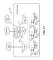
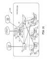
- FIG. 27illustrates an example of an enterprise mobile network.
- FIG. 28illustrates an example of how a telephone call made to PBX extension associated with a local subscriber of an enterprise is handled in the enterprise mobile network shown in FIG. 27 .
- FIG. 29illustrates an example in which someone uses a fixed SIP phone to call a user's PBX extension.
- FIG. 30illustrates an example in which someone uses a mobile device to call a user's local MSISDN number.
- FIG. 31illustrates an example in which someone uses a UC end point to call a user's UC end point.
- FIG. 32illustrates an example in which a computer/telephone integration (CTI) application installed on a UC end point is used to remotely control a mobile device.
- CTIcomputer/telephone integration
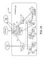
- FIG. 33illustrates an example deployment of an enterprise mobile network that includes a virtual IP PBX.
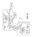
- FIG. 34is illustrates the use of security gateway (SEG) functionality in an enterprise mobile network.
- SEGsecurity gateway
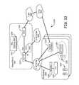
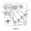
- FIG. 35illustrates how SIP-server functionality can be integrated into an MSS as a part of a FMC solution.
- FIG. 36illustrates how a SIP User Agent can be implemented in a base station subsystem.
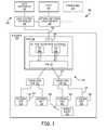
- FIG. 1illustrates one embodiment of a system 100 for providing improved wireless capacity and coverage in a building 134 .
- the system 100comprises a multiple-TRX pico base station 102 that is communicatively coupled to a public land mobile network (PLMN) 104 via a backhaul link 106 .
- PLMNpublic land mobile network
- the backhaul link 106is coupled to a base station controller (BSC) 108 , which is, in turn, coupled to a network switching subsystem (NSS) 110 .
- BSCbase station controller
- NSSnetwork switching subsystem
- the NSS 110is coupled to a public switched telephone network (PSTN) 112 (e.g., for voice communications) and to other public land mobile networks 105 .
- PSTNpublic switched telephone network
- the BSC 108is communicatively coupled to one or more data nodes (for example, a Serving GPRS Support Node (SGSN)) for communicatively coupling the BSC 108 (and the multiple-TRX pico base station 102 ) to one or more data networks 114 such as the Internet (e.g., for data communications).
- data nodesfor example, a Serving GPRS Support Node (SGSN)
- SGSNServing GPRS Support Node
- BSSBSS
- the concepts described herecan also be applied to embodiments that make use of network elements that are referred to using other terms, such as Node B, eNB, RNC, and radio access network (RAN) that are more frequently associated with 3G and 4G networks.
- RANradio access network
- the BSC 108performs various conventional BSC functions including radio channel allocation, call handovers among base stations, configuring the multiple-TRX pico base station 102 , handling alarms and performing network management functions.
- the BSC 108includes or is communicatively coupled to an appropriate network element (for example, a packet control unit (PCU)) for directing traffic to and from the data network 114 .
- PCUpacket control unit
- the NSS 110performs various conventional functions including circuit switching, and providing applications and call features to mobile subscribers, such as call ringing and roaming.
- the NSS 110typically includes a mobile switching center (MSC) and other functionality such as a home location register (HLR) and visitor location register (VLR).
- MSCmobile switching center
- HLRhome location register
- VLRvisitor location register
- certain of the features conventionally performed by the BSC 108 and NSS 110may instead be performed by the multiple-TRX pico base station 102 .
- the multiple-TRX pico base station 102may include a local server which is configured with a Linux (or other) operating system to implement these functions.
- the multiple-TRX pico base station 102comprises multiple transceiver units (TRXs) 116 .
- the multiple-TRX pico base station 102comprises two TRXs 116 .
- TRXstransceiver units
- Each of the TRXs 116is used to output a low power (specifically, less than one watt) RF channel.
- the multiple TRXs 116are implemented as a multi-carrier radio card comprising one or more digital signal processors (DSP) that produce and process baseband downlink and uplink wireless signals for each of the multiple RF channels supported by the multiple TRXs 116 , one or more upconverters to upconvert downlink wireless baseband signals to appropriate RF frequencies, and one or more downconverters to downconvert uplink RF signals received by the radio card to wireless baseband signals for processing by the one or more DSPs.
- DSPdigital signal processors
- Such a multi-carrier radio cardalso includes other conventional base station components known to those skilled in the art including, for example, filters and amplifiers (for example, an appropriate amplifier to cause the radio card to output low power RF signals).
- each of the multiple TRXs 116can also be implemented in other ways.
- a separate radio cardcan be used to implement each of the multiple TRXs 116 .
- the multiple-TRX pico base station 102comprises a suitable interface 115 to communicatively couple the multiple-TRX pico base station 102 (and the TRXs 116 included therein) to the network 104 .
- the multiple-TRX pico base station 102uses an Internet protocol (IP) backhaul connection in which voice and data signals are converted to IP packets for the communication via the backhaul link 106 to the BSC 108 (for example, using a cable modem or DSL modem).
- IPInternet protocol
- the multiple-TRX pico base station 102may use a T1 or E1 connection (that is, a time division multiplexing (TDM) connection) for the backhaul link 106 .
- TDMtime division multiplexing
- a wireless linkfor example, a WIMAX wireless link
- the interface 115would comprise a suitable WIMAX interface.
- a single backhaul link 106need be provided in order to service the multiple TRXs 116 that are included in the multiple-TRX base station 102 . This is in contrast to conventional pico base station deployments in which multiple, single TRX pico base stations are deployed, each of which requires a separate backhaul link.
- the GSM A-bis interfaceis used to communicate between the multiple-TRX pico base station 102 and the BSC 108 over the backhaul connection 106 .
- the BSC 108communicates with an MSC in the NSS 110 using the GSM A interface and a packet control unit of the BSC 108 communicates with a SGSN in the data network 114 using the GPRS Gb interface.
- the various interfacesare implemented in software executing on the multiple-TRX pico base station 102 .
- a BSC 108can communicate with one or more multiple-TRX pico base stations 102 .
- Each of the transceiver units 116communicates in a single bi-directional RF channel of a particular licensed wireless RF communications band. Each such bi-directional RF channel comprises an upstream channel and downlink channel.
- each of the transceiver units 116 of the multiple-TRX pico base station 102transmits and receives 200 kHz GSM uplink and downlink RF channels within the 850 MHz frequency band (for example, 824-849 MHz uplink and 869-894 MHz downlink).
- each of the transceiver units 116 of the multiple-TRX pico base station 102transmits and receives in 1.25 MHz CDMA uplink and downlink RF channels within the 1900 MHz frequency band (for example, 1850-1910 MHz uplink and 1930-1990 MHz downlink).
- the transceiver units 116support other wireless protocols (for example, other GSM bands, other CDMA bands and GPRS, EDGE, UMTS, W-CDMA, LTE, EVDO, CDMA2000, UMB, HSPA, and WIMAX protocols).
- the multiple-TRX pico base station 102may support multiple, different wireless protocols so that the different wireless protocols can be supported by a single multi-mode multiple-TRX pico base station 102 .
- one transceiver 116may support one wireless protocol while other transceivers 116 may support other wireless protocols.
- the multiple-TRX pico base station 102is also communicatively coupled to a distributed antenna system (DAS) 118 .
- the DAS 118comprises a multi-port repeater hub 120 which is communicatively coupled to a plurality of antenna units 122 .
- Each antenna unit 122includes or is coupled to at least one antenna 124 from which the antenna unit 122 receives and radiates RF signals.
- the DAS 118is used to provide RF wireless coverage from the remotely located and spatially separated antenna units 122 using the capacity that is provided by the multiple-TRX pico base station 102 .
- the TRXs 116 of the pico base stations 102are centralized and can be located in a secure location (for example, a utility or server closet or room).
- the hub 120is communicatively coupled to the antenna units 122 via one or more intermediate expansion hubs 126 .
- the hub 120is communicatively coupled to each of the expansion hubs 126 via one or more cables 128 .
- the cables 128comprise one or more fiber optic cables.
- the antenna units 122are communicatively coupled to the expansion hub 126 via appropriate cabling 130 (for example, thin coaxial cabling, CATV cabling, or fiber optic cabling). In other embodiments, the antenna units 122 may be communicatively coupled to the hub 120 directly without the use of intermediate expansion hubs 126 .
- the hub 120receives a downlink RF channel from each of the transceiver units 116 included in the multiple-TRX pico base station 102 .
- the hub 120downconverts each such downlink RF channel to an intermediate frequency (IF) for distribution to the antenna units 122 .
- IFintermediate frequency
- the downconverted IF channelsare combined and communicated to each expansion hub 126 over a respective fiber link 128 using an analog optical modulator.
- Each expansion hub 126receives and demodulates the optical signal to recover the combined downlink IF signal, which is then transmitted to each of the antenna units 122 that are coupled to that expansion hub 126 using the cabling 130 .
- Each antenna unit 122receives the combined IF signal and separates the IF signals into separate IF signals for each downlink RF channel received from the multiple-TRX pico base station 102 .
- the antenna unit 122then upconverts each such separated IF signal to its original RF frequency as was received from pico base station 102 .
- the upconverted downlink RF signalsare then combined and radiated from an antenna 124 coupled to the antenna unit 122 .
- a similar processis performed in the uplink direction.
- RF signals that are received from the antenna 124 coupled to that antenna unit 122are filtered in order to produce an uplink RF channel for each of the transceiver units 116 included in the multiple-TRX pico base station 102 .
- the antenna unit 122downconverts each such uplink RF channel to an intermediate frequency (IF) for distribution back to the hub 120 via an expansion hub 126 .
- IFintermediate frequency
- the downconverted IF channelsare combined and communicated to each expansion hub 126 over a cable 130 .
- Each expansion hub 126combines the various IF channels it receives from the antenna units 122 that are coupled thereto and communicates the combined IF channels to the hub 120 over a fiber link 128 using an analog optical modulator.
- the hub 120receives and demodulates the optical signal from each expansion hub 126 to recover the combined IF signal transmitted from that expansion hub 126 .
- the recovered combined IF signals from all of the expansion hubs 126are then combined.
- the hub 120then separates the combined IF signals into separate IF signals for each uplink RF channel supported by a transceiver unit 116 in the multiple-TRX pico base station 102 .
- the hub 120then upconverts each such separated IF signal to its original RF frequency as was received over the air.
- Each upconverted uplink RF channelis then communicated to a respective transceiver unit 116 in the multiple-TRX pico base station 102 .
- separation of the signalsis not required if the IF and RF frequencies are selected such that a block upconverters and block downconverters can be used (instead of using separate, individual narrowband upconverters and downconverters).
- a block upconverters and block downconverterscan be used (instead of using separate, individual narrowband upconverters and downconverters).
- the entire IF spectrumcould be upconverted as one continuous block versus having individual narrow band upconverters and likewise with the downconversion of the RF spectrum
- the DAS 118may include one or more of the following filtering, amplification, wave division multiplexing, duplexing, synchronization, and monitoring functionality as needed and as is known in the art. Also, power may also be provided to the antenna units 122 over the cabling 130 such that no additional power source is needed to power the antenna units 122 .
- a suitable DAS 118is the InterReach FUSION in-building distributed antenna system that is commercially available from ADC Telecommunications, Inc., of Eden Prairie, Minn.
- DASdigital radio frequency transport
- wireless signals communicated between the multiple-TRX pico base station 102 and the antennas 124can be transported in one or more of the following forms: analog RF form, analog IF form, analog baseband form, digitized RF form, digitized IF form, and digitized baseband form.
- the multiple-TRX pico base station 102 and the hub 120 of the DAS 118are installed in a building 134 in which coverage and capacity is to be provided.
- the building 134is not controlled by the service provider that operates the network 104 . That is, the building 134 comprises a customer premise that is owned, controlled, or otherwise used by a person or entity other than the service provider that operates the network 104 , such as an “enterprise” (for example, an “enterprise” such as a business, non-profit organization, or government entity). Examples of such buildings include, without limitation, office buildings, shopping centers, educational or governmental buildings, airports, sports or entertainment arenas or stadiums, hospitals, single family homes, condominiums, apartments, or hotels or motels.
- the multiple-TRX pico base station unit 102 and hub 120 of the DAS 118are installed within a rack 136 that is included in a utility or server room or closet of the building 134 .
- a rack 136that is included in a utility or server room or closet of the building 134 .
- at least a portion of such equipmentis “rack mountable”. That is, at least a portion of such equipment is packaged in such a way to fit within one or more standard racks 136 located within the utility room.
- racks 136enable such rack-mountable equipment to be stacked within the rack in an efficient, organized, and standard manner.
- a 19-inch rackfor example, a 19-inch rack that complies with one or more of the following standards: Electronic Industries Alliance (EIA) 310-D, International Electrotechnical Commission (IEC) 60297 and Deutsches Institut für Normung e.V (DIN) 41494 SC48D).
- EIAElectronic Industries Alliance
- IECInternational Electrotechnical Commission
- DINDeutsches Institut für Normung e.V
- the multiple-TRX pico base station 102 and the hub 120are rack mountable. That is, each respective chassis in which the various components of the multiple-TRX pico base station 102 and the hub 120 are housed and designed to fit (and be installed) in the rack 136 . Each such chassis includes appropriate fastening and structural support elements to fasten the multiple-TRX pico base station 102 and the hub 120 to the rack 136 and to support the multiple-TRX pico base station 102 and the hub 120 when installed in the rack 136 .
- the base station 102 and the hub 120are housed within the same physical chassis (for example, the same rack-mountable physical chassis).
- the antenna units 122form one or more coverage areas.
- the antenna units 122are distributed throughout the building 134 so as to form one or more coverage areas that substantially include the occupied areas within the building 134 .
- Mobile communications equipment 132within a coverage area is communicatively coupled to the network 104 via one or more of the antenna units 122 , an expansion hub 126 , the hub 120 , the multiple-TRX pico base station 102 and the backhaul 106 .
- the multiple-TRX pico base station 102 shown in FIG. 1is described above as sending and receiving RF signals with the DAS 118 . It is to be understood that in other embodiments, the transceivers 116 of the multiple-TRX pico base station 102 sends and receives other types of the signals (which are distributed by the DAS 118 and which are ultimately used to produce an RF signal in the downlink and which were originally received as an RF signal in the uplink).
- the transceivers 116 and the DAS 118can communicate using IF signals, in which case, in the downlink, the transceivers 116 upconvert the downlink baseband signals to appropriate IF frequencies and, in the uplink, the DAS 118 provides IF signals to the transceivers 116 , which downconvert the received IF signals to baseband for processing.
- analog baseband signals or digital datacan be communicated between the transceivers 116 and the DAS 118 (in which case, in the downlink direction, the RF signals are ultimately produced in the DAS 118 and, in the uplink direction, the DAS 118 receives the original RF signals from mobile equipment 132 and processes the RF signals in order to produce the desired signal for communication to the transceivers 116 ).
- FIG. 2is a block diagram of an alternative embodiment of a multiple-TRX pico base station 202 .
- the multiple-TRX pico base station 202 shown in FIG. 2comprises multiple TRXs 116 .
- the multiple-TRX pico base station 202 of FIG. 2also comprises at least a portion of the base station controller functionality 208 necessary to control the multiple TRXs 116 included in the multiple-TRX pico base station 202 and for the multiple-TRX pico base station 202 to communicate with a PLMN 204 (for example, with the NSS 110 and/or a data network 114 ).
- the base station controller functionality 208is implemented in software that executes on one or more programmable processors that are included in the multiple-TRX pico base station 202 .
- the BSC functionality 208implements at least a portion of the GSM A interface in order to communicate with the NSS 110 over the backhaul 106 and implements at least part of the GPRS Gb interface in order to communicate with a SGSN included in the data network 114 .
- FIG. 3is a block diagram of one such alternative embodiment of a multiple-TRX pico base station 302 .
- the multiple-TRX pico base station 302 shown in FIG. 3comprises multiple TRXs 116 .
- base station control functionality 308necessary to control the multiple TRXs 116 included in the multiple-TRX pico base station 302 and for the multiple-TRX pico base station 302 to communicate with a PLMN 304 (for example, with the public NSS 110 and/or a data network 114 ).
- the base station controller functionality 308is implemented in software that executes on one or more programmable processors that are included in the multiple-TRX pico base station 302 .
- the multiple-TRX pico base station 302 shown in FIG. 3also includes NSS functionality 310 .
- the NSS functionality 310implements at least a portion of the call switching functionality normally implemented in a MSC (for example, GSM media gateway (MGW) functionality 340 ).
- MSCfor example, GSM media gateway (MGW) functionality 340
- MGWGSM media gateway
- the MGW functionality 340 in the multiple-TRX pico base station 302is able to locally switch the call traffic for that call when instructed to do so by a public MSC included in the public NSS 110 .
- the call trafficneed not be backhauled back to the public MSC in the public NSS 110 and only the signaling traffic necessary to establish the calls needs to be backhauled to the public MSC.
- the NSS functionality 310implements an appropriate interface (for example, the GSM Mc interface) between the MGW functionality 340 and the public MSC in order to permit the public MSC to control the MGW functionality 340 via the backhaul link 106 .
- the NSS functionality 310is implemented in software that executes on one or more programmable processors that are included in the multiple-TRX pico base station 310 (for example, the same one or more processors that execute the software that implements the BSC functionality 308 ).
- FIG. 4is a block diagram of one such alternative embodiment of a multiple-TRX pico base station 402 .
- the multiple-TRX pico base station 402 shown in FIG. 4comprises multiple TRXs 116 .
- base station control functionality 408necessary to control the multiple TRXs 116 included in the multiple-TRX pico base station 402 and for the multiple-TRX pico base station 402 to communicate with a PLMN 404 (for example, with the public NSS 110 and/or a data network 114 ).
- the base station controller functionality 408is implemented in software that executes on one or more programmable processors that are included in the multiple-TRX pico base station 402 .
- the multiple-TRX pico base station 402comprises NSS functionality 410 .
- the NSS functionality 410includes MGW functionality 440 as described above in connection with FIG. 3 .
- the NSS functionality 410 in the embodiment shown in FIG. 4also implements private GSM MSC server functionality (MSC-S) 442 and a private home location register (HLR) 444 .
- MSC-SGSM MSC server functionality
- HLRprivate home location register
- the private MSC-S functionality 442 and the private HLR 444enable the NSS functionality 410 to perform full mobility management and call management for calls between mobile stations 132 that are communicating with the multiple-TRX pico base station 402 or between one or more mobile stations 132 that are communicating with the multiple-TRX pico base station 402 and one or more pieces of fixed equipment 456 (or other SIP entities) that are located within the building 134 .
- the fixed equipment 456comprises voice over IP (VOIP) telephones that are communicatively coupled to an IP PBX 454 over a corporate IP local area network (LAN) 450 .
- VOIPvoice over IP
- the NSS functionality 410further comprises a Session Initiation Protocol (SIP) agent 452 to enable the private MSC-S functionality 442 and the IP PBX 454 to use the SIP protocol to establish sessions between the mobile equipment 132 (which do not otherwise support the SIP protocol) and the fixed equipment 456 .
- the SIP agent 452enables the private MSC-S functionality 442 to establish sessions with other network entities that support the SIP protocol including, for example, a unified communication server 458 (for example, the MICROSOFT OFFICE COMMUNICATIONS SERVER 2007). As a result, such sessions can be established without using the PSTN 112 or the PLMN 404 .
- SIPSession Initiation Protocol
- the private MSC-S functionality 442can be configured to support call handovers to the PLMN 404 or other PLMN 105 in the event that such a mobile station 132 moves outside of the coverage area of the pico base station 402 while such a session is still in progress.
- the private MSC-S functionality 442can be configured to support inbound handovers from another MSC when such a mobile station 132 comes into the coverage area of the pico base station 402 .
- the MGW functionality 440communicates, for example, with a SIP session border controller (SBC) 460 in order to communicate the call traffic between the mobile equipment 132 and the fixed equipment 456 (or other SIP entities) and perform any transcoding that is required.
- SBCSIP session border controller
- the private MSC-S functionality 442 and private HLR 444are “private” in the sense that such functionality is only used for establishing sessions among licensed-RF-spectrum mobile stations 132 that are in the private HLR 444 and SIP-enabled equipment that is communicatively coupled to the corporate IP LAN 450 .
- each mobile station 132 that is in the private HLR 44is also in a public HLR within the PLMN 404 .
- the MSC-S functionality of the public MSCis used to establish such a call, in which case the public MSC interacts with pico base station 402 in the conventional manner.
- the MSC-S functionality of the public MSC in the public NSS 110is used to establish such a call (directly or by interacting with another public NSS), in which case the public MSC in the NSS 110 interacts with pico base station 402 in the conventional manner.
- the MSC-S functionality and HLR integrated into the pico base station 402is “public” and acts as conventional MSC-S and HLR in such scenarios (for example, by including other NSS functionality such as a visitor location register (VLR) and prepaid services (PPS)).
- VLRvisitor location register
- PPSprepaid services
- features that are provided by the unified communication server 458can be provided to the non-SIP-enabled mobile devices that are in the private HLR 444 .
- the private MSC-S functionality 442can be configured to route calls from mobile equipment 132 to the PSTN 112 via the IP PBX 454 and its connection to the PSTN 112 (for example, where doing so results in the least cost to the enterprise).
- supplemental servicescan be implemented locally using the IP PBX 454 and the private MSC-S functionality 442 of the multiple-TRX pico base station 402 .
- a user who has both a fixed VOIP telephone coupled to the IP PBX 454 and a mobile device that communicates with the multiple-TRX pico base station 402can have outside calls that come into either device forwarded to the other device such that both devices ring when such an outside calls comes in.
- voice mail messages that are received via either devicecan be routed to the unified communication server 458 (for example, for delivery via a user's email account), thereby providing a single repository of voice mail messages.
- the above-mentioned enhanced SIP-related featurescan be provided to licensed-RF-spectrum (i.e., GSM) mobile devices that are in the private HLR 444 while still permitting other licensed-RF-spectrum mobile devices to communicate with the PLMN 404 or another PLMN 105 using conventional cellular technology.
- licensed-RF-spectrumi.e., GSM
- the NSS functionality 410is implemented in software that executes on one or more programmable processors that are included in the multiple-TRX pico base station 410 (for example, the same one or more processors that execute the software that implements the BSC functionality 408 ).
- the functionality described above in connection with FIGS. 3 and 4can, in other embodiments, also be implemented using base stations other than multiple-TRX pico base stations (for example, using single-TRX pico base stations, micro base stations, and macro base stations). Moreover, such functionality is described above as being implemented in an integrated base station device. It is to be understood, however, that in some other embodiments, such functionality is implemented using separate network nodes.
- the various elements described abovecan be deployed in various architectures and usage scenarios.
- FIG. 5illustrates one example of a distributed architecture 500 in which the technology described above (for example, a multiple-TRX pico base station and DAS) can be deployed to provide coverage and capacity to GSM/GPRS mobile devices while in an enterprise 502 .
- a pico base station subsystem 504is coupled to a DAS 506 .
- the pico base station 504is communicatively coupled to a corporate IP local area network 508 (using a GSM Ater-over-IP interface for calls and a GPRS Gb-over-IP interface for data).
- the corporate IP LAN 508is used to gain access to the wireless service operator's central office 510 via an IP Network 512 , where a MSC server (MSC-S) 514 , a media gateway (MGW) 516 , and GSN 518 are located.
- MSC-SMSC server
- MGWmedia gateway
- GSNGSN 518
- a router 532is used to communicatively couple the IP network 512 to the various elements of the operator's central office 510 .
- the MSC- 514handles signaling traffic routed to the central office 510 and controls the MGW 516 .
- the MSC-S 514includes a SIP user agent (UA) 530 to handle SIP-related signaling (as described below).
- the MGW 516switches calls and performs any needed media conversion (for example, conversions between formats used in the enterprise 502 and formats used in the public switched telephone network or by a another PLMN (collectively shown at reference numeral 526 in FIG. 5 )).
- the GSN 518is also coupled to an IP network 528 (over the Gb interface) and implements conventional SGSN functionality.
- the NSS functionalityis centralized in the central office 510 while the base station subsystem (BSS) is located in the enterprise 502 .
- the pico base station subsystem 504implements functionality similar to that described above in connection with FIGS. 3 and 4 to enable the pico base station subsystem 504 to locally switch sessions among mobiles 520 that are within its coverage area and/or sessions with an IP PBX 522 (and the SIP phones 534 coupled thereto).
- the IP PBX 522 and the SIP phones 534are coupled to the pico base station subsystem 504 over the corporate local area network 508 using a SIP session border controller (SBC) 524 , which manages the signaling and media streams for sessions established with such devices (implementing, for example, a Back-to-Back User-Agent).
- SBC 524handles, for example, transcoding and NAT traversal (using, for example, the Interactive Connectivity Establishment (ICE) protocol or the Session Traversal Utilities for NAT (STUN) protocol).
- ICEInteractive Connectivity Establishment
- STUNSession Traversal Utilities for NAT
- the NSS functionalityis centralized and located in the operator's central office 510 , which makes it easier to maintain such NSS functionality.
- firewallsare typically used to communicatively couple such NSS functionality to the pico base station subsystem 504 in the enterprise 502
- some mechanismfor Internet Protocol Security (IPsec) software
- IPsecInternet Protocol Security
- QOSquality of service
- communications between the NSS functionality located in the operator's central office 510 and the pico BSS 504 in the enterprise 502involve at least one Network Address Translation (NAT) traversal.
- NATNetwork Address Translation
- FIG. 6illustrates another architecture 600 for an enterprise mobile phone system 601 where an enterprise 602 connects a media gateway (MG) 604 and a mobile switching center server (MSS) 606 to the enterprise's IP-based Intranet 608 .
- MGmedia gateway
- MSSmobile switching center server
- a pico base station subsystem 610 and a DAS 612are installed and are coupled to the MG 604 and MSS 606 via the enterprise's Intranet 608 .
- the pico BSS/DAS equipment installed in the various offices 603 of the enterprise 602can share the MG 604 and MSS 606 via the Intranet 608 .
- the MG 604 and the MSC-S 606are communicatively coupled to a wireless operator's PLMN 616 using a suitable backhaul link (for example, TDM links).
- a suitable backhaul linkfor example, TDM links.
- the pico BSS 610 , DAS 612 , MG 604 , MSS 606 , and the Intranet 608are located in the enterprise.
- the elements of the enterprise mobile phone system 601are communicatively coupled to one another using the Intranet 608 (the solid lines betweens such elements and the Intranet 608 depict IP communication links).
- SS7 and GSM compatible signaling(for example, signaling formatted according to the ISDN user part (ISUP) and mobile application part (MAP) protocols) are communicated between nodes in the operator's PLMN 616 and the MSS 606 and between the MSS 606 and the pico BSS 610 .
- SS7-related signalingis shown in FIGS. 6-10 using dashed lines.
- the call-related media streamsare communicated between the pico BSS 610 and the MG 604 using the Real-time Transport Protocol (RTP).
- RTPReal-time Transport Protocol
- the MSS 606controls the various media gateway functions in the system 601 using, for example, the Media Gateway Control Protocol (MGCP).
- MGCPMedia Gateway Control Protocol
- SIGTRANis also used to communicate signaling data over the IP links.
- FIG. 7illustrates an architecture 700 that is similar to the one shown in FIG. 6 (and those elements that are the same as the ones used in the example shown in FIG. 6 are referenced in FIG. 7 using the same reference numerals used in FIG. 6 ).
- Architecture 700is extended to further include an enterprise IP phone system 720 that is deployed in the enterprise.
- the enterprise IP phone system 720includes an IP PBX 722 that supports communications with SIP phones 724 .
- a SIP Session Border Controller (SBC) 726is used to couple the SIP phones 724 to Intranet 608 .
- the SBC 726manages the signaling and media streams for sessions established with such devices and performs any needed transcoding.
- SBCSession Border Controller
- the MSS 606includes a SIP user agent (SIP UA) 614 to set up sessions between mobiles 618 that are being handled by the pico BSS 610 and SIP Phones 724 or the IP PBX 722 .
- Ses between such mobiles 618 and devices that are coupled to the PSTN 728can be setup using the SIP UA 614 and the connection to the PSTN 728 provided by the IP PBX 722 .
- sessions between such mobiles 618 and devices that are coupled to the PSTN 728can be routed through the operator's PLMN 616 (as is the case with the example shown in FIG. 6 ).
- a firewallis not used to couple the MSS 606 , MG 604 , and each of the pico BSSs 610 to the Intranet 608 .
- IPSec and SRTPare not needed to secure communications among these devices. If the intranet backhaul bandwidth and QOS is sufficient to support the services provided by the enterprise mobile phone system 601 (for example, by using a dedicated VPN) then special QOS features and devices are not required to provide such backhaul. If backhaul QOS is an issue, a resource reservation mechanism may be needed to prioritize data flows and to help ensure a desired quality of service.
- the MSS 606 , MG 604 , and each of the pico BSSs 610are assigned a respective Intranet IP address, and communications among those devices do not involve any NAT traversals.
- FIG. 8illustrates an architecture 800 that is similar to the one shown in FIG. 6 (and those elements that are the same as the ones used in the example shown in FIG. 6 are referenced in FIG. 8 using the same reference numerals used in FIG. 6 ).
- the example architecture 800 shown in FIG. 8is similar to the example shown in FIG. 6 except that the MSS 606 , MG 604 , and pico BSSs 610 are coupled to one another over the public Internet 830 instead of an enterprise's Intranet.
- firewalls 832are needed to couple the MSS 606 , MG 604 , and each pico base station subsystem 610 to the Internet 830 .
- IPSec and SRTPare used to secure communications among these devices
- QOSis used to prioritize data flows and to help ensure a desired quality of service for communications among these devices using the Internet 830 .
- each of the MSS 606 , MG 604 , and each pico base station subsystem 610is assigned an Internet IP address, and communications among those devices occurs over the Internet 830 .
- FIG. 9illustrates an example architecture 900 that is similar to the one shown in FIGS. 7-8 (and those elements that are the same as the ones used in the examples shown in FIGS. 7-8 are referenced in FIG. 9 using the same reference numerals used in FIGS. 7-8 ).
- the example architecture 900 shown in FIG. 9is similar to the example shown in FIG. 7 except that the one shown in FIG. 9 uses an enterprise's Intranet 934 and the Internet 830 to integrate an IP PBX 722 and SIP Phones 724 into the system.
- the SIP user agent (SIP UA) 614 included in the MSS 606is used to set up sessions between mobiles 618 that are being handled by the MSC-S 606 and SIP Phones 724 or the IP PBX 722 .
- Sessions between mobiles 618 and the PSTN 728can be setup using the SIP UA 614 , in which case the connection to the PSTN 728 is provided by the IP PBX 722 .
- the SBC 726 , IP PBX 722 and SIP Phones 724are located behind the firewall 832 that stands between the Intranet 934 and the Internet 830 .
- the IP PBX 722 and SIP Phones 724are assigned Intranet IP addresses, and communications that go through the SBC 726 involve a NAT traversal.
- the SBC 726manages the signaling and media streams for sessions established with such devices (implementing, for example, a Back-to-Back User-Agent).
- the SBC 726handles, for example, transcoding and NAT traversal (using, for example, the Interactive Connectivity Establishment (ICE) protocol or the Session Traversal Utilities for NAT (STUN) protocol).
- ICEInteractive Connectivity Establishment
- STUNSession Traversal Utilities for NAT
- IPSec and SRTPare needed to secure communications among the MSS 606 , MG 604 , the pico BSSs 610 , and the enterprise IP phone system 720 that occur over the Internet 830 .
- QOSis needed to prioritize data flows and to help ensure a desired quality of service for communications among the MSS 606 , MG 604 , and the pico BSSs 610 that occur over the Internet 830 .
- FIG. 10illustrates an example architecture 1000 that is similar to the example shown in FIG. 9 (and those elements that are the same as the ones used in the example shown in FIG. 9 are referenced in FIG. 10 using the same reference numerals used in FIG. 9 ).
- the example architecture 1000 shown in FIG. 10is similar to the example shown in FIG. 9 except that each pico BSS/DAS deployment is also coupled to an enterprise's Intranet 934 .
- each pico base station 610is assigned an Intranet IP address and is behind the Intranet's firewall 832 .
- Communications between the pico base station 610 and either the MSS 606 or the MG 604traverse the Intranet's NAT and go over the Internet 830 and, therefore, IPSec/SRTP is used to secure such communications and QOS is used to help ensure a desired quality of service.
- FIG. 11illustrates one such scenario in which the technology described here is used to provide wireless local loop (WLL) service for both voice and data within an enterprise (for example, using low-power RF spectrum) to implement an enterprise mobile network 1100 to provide wireless service within the enterprise.
- WLLwireless local loop
- a MSS 1102provides MSC, HLR, and PPS services for local mobiles 1104 that are local subscribers to that enterprise mobile network 1100 and provides no roaming for any non-local mobiles that happen to roam into a coverage area associated with the enterprise.
- Sessionscan be established between a local mobile 1104 and a non-local device via the PSTN 1106 .
- a media gateway (MG) 1112is used to communicatively couple the elements of the enterprise mobile network 1100 to the PSTN 1106 and, under control of the MSS 1102 , to switch call media streams between mobiles 1104 and devices connected to the PSTN 1106 and to perform any needed transcoding.
- a GPRS Support Node (GSN) 1114is included in the private network 1100 to provide GPRS data service to local mobiles 1104 .
- the GSN 1114is coupled to the Internet 1116 using a firewall 1118 .
- the elements of the enterprise mobile network 1100are communicatively coupled to one another using the enterprise's IP Intranet 1120 .
- FIG. 12illustrates another scenario in which the technology described here is used to provide only roaming service within an enterprise.
- the MSS 1202implements MSC/VLR functionality to support such roaming.
- the enterprise mobile network 1200is used to provide roaming services to other wireless networks and does not itself have any local subscribers.
- the MSS 1202 of the enterprise mobile network 1200appears to be another MSC/VLR of the PLMN 1222 .
- the MSS 1202 of the enterprise network 1200communicates with the other elements of the PLMN 1222 using the MAP protocol.
- a media gateway 1224is used to communicatively couple the elements of the enterprise network 1200 to the PLMN 1222 and, under control of the MSS 1202 , to switch call media streams between mobiles 1104 and devices connected to the PLMN 1222 and to perform any needed transcoding. Authentication and other functions are provided by the NSS functionality of the PLMN 1222 . Otherwise, the enterprise mobile network 1200 is similar to the enterprise mobile network 1100 of FIG. 11 .
- FIG. 13illustrates another usage scenario in which an enterprise mobile network 1300 is configured to support both local subscribers and “hybrid” subscribers.
- hybrid subscribersare both local subscribers of the enterprise mobile network 1300 and subscribers of the PLMN 1222 .
- each hybrid subscriberhas a local MSISDN that is assigned by the enterprise mobile network 1300 and a public MSISDN that is assigned by the PLMN 1222 .
- a location updateis performed with the MSS 1302 of the enterprise mobile network 1300 .
- the local MSS 1302acts as a MSC/VLR for the hybrid subscriber's public MSISDN number and communicates with the public HLR (not shown) in the PLMN 1222 to complete a location update for the hybrid subscriber's public MSISDN number using the MAP/D protocol. Also, the local MSS 1302 , in connection with such a location update, performs a location update for the hybrid subscriber's local MSISDN number and handles both the MSC/VLR and HLR/PPS functions for the location update.
- the hybrid subscriberwhen a hybrid subscriber is within a coverage area associated with the enterprise mobile network 1300 , the hybrid subscriber is able to receive calls made to both its local MSISDN number and its public MSISDN number. When the hybrid subscriber is outside of the coverage area of the enterprise mobile network 1300 , the hybrid subscriber is only able to receive calls made to its public MSISDN number.
- the MSS 1302 of the enterprise mobile network 1300also acts as a MSC/VLR to support handovers and the like, as well.
- FIG. 14illustrates another usage scenario in which an enterprise mobile network 1400 also includes Private A-link Intelligent Multiplexer (PALIM) switching function 1426 to support three types of subscribers—private subscribers (subscribers that are subscribers of only the private enterprise mobile network 1400 ), hybrid subscribers (subscribers that are subscribers of both the private enterprise mobile network 1400 and the public PLMN 1222 ), and public subscribers (subscribers that are subscribers of the public PLMN 1222 and not a subscriber of the private enterprise mobile network 1400 ).
- the PALIM switching technology 1426enables the enterprise mobile network 1400 to provide local NSS functionality for private and hybrid subscribers that are within a coverage area of the enterprise mobile network 1400 while supporting roaming for public subscribers.
- PALIMPrivate A-link Intelligent Multiplexer
- the PALIM function 1426is used to logically couple the rest of the elements of the enterprise mobile network 1400 to the PLMN 1222 using the GSM A interface so that the enterprise mobile network 1400 appears, from the perspective of the PLMN 1222 , as another base station subsystem of the PLMN 1222 in connection with providing service to public subscribers and to hybrid subscribers in connection with their public MSISDN numbers.
- the enterprise mobile network 1400provides full NSS functionality (that is, MSC/VLR and HLR/PSS functions).
- FIG. 15illustrates an example in which an enterprise mobile network 1500 is implemented across two offices of an enterprise.
- two intranets 1520in respective offices A and B) are communicatively coupled to one another using a virtual private network (VPN) connection (using, for example, the IPSec protocol).
- VPNvirtual private network
- the MSS 1402 and GSN 1114are deployed in Office A, while the PSTN connection and associated MG 1112 is located in Office B.
- Mobile network trafficis routed among the Intranets 1520 using the underlying IP network technology.
- FIG. 16illustrates an example in which two separate enterprise mobile networks 1600 share a GSN 1614 and MSS 1602 .
- the GSN 1614 and MSS 1602are located in a wireless operator's central office 1628 and are connected to the respective intranets 1620 of the two enterprises using a VPN.
- Mobile network trafficis routed among the Intranets 1620 and the MSS 1602 and GSN 1614 using the underlying IP network technology.
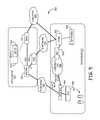
- FIG. 17illustrates an example in which an IP PBX 1730 is integrated with the enterprise mobile network 1700 .
- a SIP User Agent (SIP UA) 1732 included in the MSS 1702enables wireless mobile devices 1104 to use the SIP protocol to establish sessions with SIP phones 1734 that are attached to the IP PBX 1730 .
- the IP PBX 1730is coupled to the PSTN 1106 via a media gateway 1740 .
- the IP PBX 1730can be configured to associate PBX extension numbers with local subscribers of the enterprise mobile network 1700 (for example, private and hybrid subscribers). For example, where a local subscriber also has a fixed SIP phone 1734 that has a particular PBX extension number, the IP PBX 1730 and MSS 1702 can be configured to associate the same PBX extension number with the local subscriber's mobile 1104 and calls made to that PBX extension cause both the SIP phone 1734 and the mobile 1104 to ring. In this way, the mobile devices 1104 can act as wireless extensions of the IP PBX 1730 .
- FIG. 18illustrates an example in which an access gateway 1836 is integrated with the enterprise mobile network 1800 .
- the access gateway 1836is used to couple SIP devices to other types of voice networks.
- the access gateway 1836is used to couple SIP devices to the PSTN 1106 using an analog trunk line 1838 .
- the SIP User Agent 1732 included in the MSS 1702enables the MSS 1702 to use the access gateway 1836 to gain access to the devices and networks coupled to it (such as the SIP phones 1734 and analog phones 1840 ).
- FIGS. 19-36illustrate additional examples of services and usage scenarios that can be implemented using the technology described here.
- FIG. 19illustrates one example of an enterprise mobile network 1900 in which the technology described above (for example, a multiple-TRX pico base station and DAS) can be deployed to provide coverage and capacity to GSM/GPRS mobile devices 1902 located within an enterprise 1904 .
- the enterprise mobile network 1900is not coupled to any PLMN and is also referred to here as an “isolated” enterprise mobile network 1900 .
- the enterprise 1904must gain access to suitable GSM spectrum, which is typically licensed spectrum.
- suitable GSM spectrumwhich is typically licensed spectrum.
- one way in which an enterprise 1904 may access suitable GSM spectrum for use in such an isolated enterprise mobile network 1900is to obtain a license to use low-power RF spectrum that is available in some jurisdictions.
- a pico base station subsystem 1906is coupled to a DAS 1908 .
- the enterprise mobile network 1900also comprises a mobile switching subsystem (MSS) 1910 that is coupled to the pico base station subsystem 1906 and is also located in the enterprise 1904 .
- the MSS 1910provides all the NSS related functions for the enterprise mobile network 1900 .
- the MSS 1910is coupled to the PSTN 1912 via an analog PBX 1914 .
- the analog PBX 1914is also coupled to various analog phones 1916 .
- a media gateway 1918is used provided to perform any needed media conversions between the media formats used by the MSS 1910 and pico base station subsystem 1906 and the media formats used by the analog PBX 1914 .
- the enterprise mobile network 1900also includes a GSN 1920 that is coupled to the Internet 1922 .
- the GSN 1920is used to provide GPRS data service to the mobile device 1902 while they are camped on the enterprise mobile network 1900 .
- the enterprise mobile network 1900is configured to be used with the same mobile devices 1902 that the users use when they are outside of the coverage area of the enterprise mobile network 1900 . That is, in this example, the mobile devices 1902 (and the associated subscriber identity module (SIM) cards) have a home PLMN that is not the enterprise mobile network 1900 .
- the enterprise mobile network 1900is configured to be used with these mobile devices 1902 without requiring the users to change their subscriber identity module (SIM) cards. If the coverage area of a user's home PLMN overlaps with the coverage area of the enterprise mobile network 1900 , the user may need to manually select the appropriate network to use.
- Each local user of the enterprise mobile network 1900registers with the network 1900 using the International Mobile Equipment Identity (IMEI) assigned to the user's mobile device 1902 (which the user can access from the mobile device 1902 itself via the device's user interface).
- IMEIInternational Mobile Equipment Identity
- Each local user(also referred to here as a “local subscriber”) is assigned a local phone number (local MSISDN) that is used by the enterprise mobile network 1900 to provide wireless cellular service to that local subscriber.
- local MSISDNlocal phone number
- each such userhas a regular public mobile phone number that is used in the user's home PLMN and a local mobile phone number that can be used in the enterprise mobile network 1900 .
- each local subscriberhas an associated analog phone 1916 that has an associated PBX extension number.
- the usercan use the call forwarding function provided by the user's home PLMN to, while the user is not camped onto the home PLMN, forward calls that are made to the user's public phone number to the user's PBX extension number.
- the PBX 1914supports a twin ring feature and is configured so that when a call is made to the user's PBX extension number, the PBX 1914 causes both user's analog fixed phone 1916 and mobile phone 1902 (using the user's local mobile phone number) to ring for that call.
- the PBX 1914rings the mobile phone 1902 by forwarding the associated signaling and call data to the MSS 1910 .
- FIG. 20illustrates another example of an enterprise mobile network 2000 in which the technology described above (for example, a multiple-TRX pico base station and DAS) can be deployed to provide coverage and capacity to GSM/GPRS mobile devices 2002 located within an enterprise 2004 .
- the technology described abovefor example, a multiple-TRX pico base station and DAS
- the enterprise mobile network 2000gains access to RF spectrum by entering into an agreement with the operator of a PLMN 2006 .
- the enterprise mobile network 2000is configured to support local subscribers and non-local subscribers (that is, roamers).
- a pico base station subsystem 2008 and DAS 2010is provided within each office of the enterprise 2004 .
- a local MSS 2012is provided in the enterprise 2004 that is coupled to the pico base station subsystem 2008 .
- the local MSS 2012is also coupled to a central MSS 2014 located in the operator's central office 2016 .
- the local MSS 2012serves as the MSC/VLR for those mobile devices 2002 that are located within a coverage area associated with the enterprise mobile network 2000
- the central MSS 2014implements the GMSC and HLR functionality for all of the offices of the enterprise 2004 and the local subscribers thereof.
- Each local MSS 2012is coupled to the central MSS 2014 over an IP Network 2018 using the MAP and ISUP protocols.
- the enterprise mobile network 2000also includes a GSN 2020 that is coupled to the mobile devices 2002 in each office of the enterprise 2004 via the IP network 2018 .
- the GSN 2020is used to provide GPRS data service to the mobile device 2002 while they are camped on the enterprise mobile network 2000 .
- the GSN 2020is also connected to an IP network 2022 via which the GPRS service is provided.
- the central office 2016also includes a media gateway (MGW) 2024 that switches calls and performs any needed media conversion.
- the central office 2016also includes a router 2026 for coupling the MSS 2014 , GSN 2020 , and MGW 2024 to the IP network 2018 .
- Each local MSS 2012is also coupled to the PSTN 2026 via an analog PBX 2028 .
- the analog PBX 2028is also coupled to various analog phones 2030 .
- a media gateway 2032is used provided to perform any needed media conversions between the media formats used by local MSS 2012 and pico base station subsystem 2008 and the media formats used by the analog PBX 2028 .
- the HLR in the central MSS 2014is the HLR for the enterprise's local subscribers and is managed by the operator of the PLMN 2006 .
- the local subscriberscan be registered using their IMSI numbers.
- the local subscribersare otherwise provided service in a manner similar to that described above in connection with FIG. 19 (including, for example, the integration with PBX 2028 ).
- the enterprise mobile network 2000is also used to provide wireless service to non-local subscribers (including subscribers of the PLMN 2006 and roamers).
- the local MSS 2012serves as the MSC/VLR and the roaming service is provided using the roaming arrangements and functionality in the PLMN 2006 , which the local MSS 2012 accesses via the IP network 2018 .
- FIG. 21illustrates another example of an enterprise mobile network 2100 in which the technology described above (for example, a multiple-TRX pico base station and DAS) can be deployed to provide coverage and capacity to GSM/GPRS mobile devices 2102 located within an enterprise 2104 .
- the technology described abovefor example, a multiple-TRX pico base station and DAS
- FIG. 21illustrates another example of an enterprise mobile network 2100 in which the technology described above (for example, a multiple-TRX pico base station and DAS) can be deployed to provide coverage and capacity to GSM/GPRS mobile devices 2102 located within an enterprise 2104 .
- base station capacityis deployed within each office of the enterprise 2104 and all NSS functions are performed in a PLMN 2106 .
- the enterprise mobile network 2100does not have local subscribers and, instead, is a part of the PLMN 2106 .
- a pico base station subsystem 2108 and DAS 2110is provided within each office of the enterprise 2104 .
- Each pico base station subsystem 2108is coupled to the NSS functionality of the PLMN 2106 via an IP network 2112 .
- a MSS 2114 , a GSN 2116 , and a MGW 2118are deployed within a central office 2120 of the operator of the PLMN 2106 .
- the MSS 2114serves as the MSC/VLR for the mobile devices 2102 that are within a coverage area associated with the enterprise 2104 .
- the GSN 2116is used to provide GPRS data service to the mobile device 2102 while they are camped on the enterprise mobile network 2100 .
- the GSN 2116is also connected to an IP network 2122 via which the GPRS service is provided.
- the central office 2120also includes and MGW 2118 that switches calls and performs any needed media conversion.
- the central office 2120also includes a router 2124 for coupling the MSS 2114 , GSN 2116 , and MGW 2118 to the IP network 2112 .
- the enterprise mobile network 2100can be configured to implement various types of location based services such as the use of a call routing table to selectively route calls, Computer Supported Telecommunications Applications (CSTA)/Call Detail Record (CDR) integration, location based tariffs, virtual HLR/VLR support, local switching, and distributed mobile station roaming number (MSRN) support.
- CSTAComputer Supported Telecommunications Applications
- CDRCall Detail Record
- MSRNdistributed mobile station roaming number
- FIG. 22illustrates another example of an enterprise mobile network 2200 in which the technology described above (for example, a multiple-TRX pico base station and DAS) can be deployed to provide coverage and capacity to GSM/GPRS mobile devices 2202 located within an enterprise 2204 .
- the technology described abovefor example, a multiple-TRX pico base station and DAS
- This exampleillustrates how the enterprise mobile network 2200 can be integrated with an IP PBX.
- the enterprise mobile network 2200gains access to RF spectrum by entering into an agreement with the operator of a PLMN 2206 .
- enterprise mobile network 2200is configured to support local subscribers and non-local subscribers (that is, roamers).
- a pico base station subsystem 2208 and DAS 2210is provided within each office of the enterprise 2204 .
- each pico base station subsystem 2208is coupled to a MSS 2212 located in the operator's central office 2214 .
- the MSS 2212serves as the MSC/VLR for those mobile devices 2202 that are located within a coverage area associated with the enterprise mobile network 2200 .
- the MSS 2212implements the GMSC and HLR functionality for all of the local subscribers of all of the offices of the enterprise 2202 .
- Each pico base station subsystem 2208is coupled to the MSS 2212 over an IP Network 2216 using an “Ater over IP” interface.
- the enterprise mobile network 2200also includes a GSN 2218 that is coupled to the mobile devices 2202 in each office of the enterprise 2204 via the IP network 2216 .
- the GSN 2218is used to provide GPRS data service to mobile devices 2202 while they are camped on to the enterprise mobile network 2200 .
- the GSN 2218is also connected to an IP network 2220 via which the GPRS service is provided.
- the central office 2214also includes a media gateway (MGW) 2222 that switches calls and performs any needed media conversion.
- the central office 2214also includes a router 2224 for coupling the MSS 2212 , GSN 2218 , and MGW 2222 to the IP network 2216 .
- the HLR in the MSS 2212is the HLR for the enterprise's local subscribers and is managed by the operator of the PLMN 2206 .
- the local subscriberscan be registered using their IMSI numbers.
- the enterprise mobile network 2200is also used to provide wireless service to non-local subscribers (including subscribers of the PLMN 2206 and roamers).
- the MSS 2212serves as the MSC/VLR and the roaming service is provided using the roaming arrangements and functionality in the PLMN 2206 , which the MSS 2212 accesses via the IP network 2216 .
- Each pico base station subsystem 2208is also coupled to the PSTN 2226 via an IP PBX 2228 .
- the IP PBX 2228is also coupled to various SIP phones 2230 .
- Each pico base station subsystem 2208is coupled to the IP PBX 2228 via a corporate IP LAN 2232 .
- a SIP session border controller (SBC) 2234which manages the signaling and media streams for sessions established with mobile devices 2202 .
- the SBC 2234routes SIP signaling data for such sessions between a SIP User Agent (SIP UA) 2236 in the MSS 2212 and the IP PBX 2228 as needed by routing media streams for such sessions among the pico base station subsystem 2208 (for ultimate communication with the mobile devices 2202 ) and the SIP phones 2230 . Also, in this example, the SBC 2234 handles transcoding media streams communicated between the SIP phones 2230 and the mobile devices 2202 and any NAT traversals.
- SIP UASIP User Agent
- the enterprise mobile network 2200is configured to be used with the same mobile devices 2202 that the users use when they are outside of the coverage area of the enterprise mobile network 2200 . That is, in this example, the mobile devices 2202 (and the associated SIM cards) have a home PLMN that is not the enterprise mobile network 2200 .
- the enterprise mobile network 2200is configured to be used with these mobile devices 2202 without requiring the users to change their SIM cards. If the coverage area of a user's home PLMN overlaps with the coverage area of the enterprise mobile network 2200 , the user may need to manually select the appropriate network to use.
- Each local subscriber of the enterprise mobile network 2200is registered with the network 2200 and is assigned a local phone number (local MSISDN) that is used by the enterprise mobile network 2200 to provide wireless cellular service to that local subscriber.
- each such local subscriberhas a regular public mobile phone number (also referred to here as the “public MSISDN” or “home MSISDN”) that is used in the user's home PLMN 2206 (and for which the user has an associated record in the main home HLR in the home PLMN 2206 ) and a local mobile phone number that is used in the enterprise mobile network 2200 (and for which the user has an associated record in the enterprise HLR that the MSS 2212 maintains).
- each local subscriberhas an associated SIP phone 2230 that has an associated PBX extension number, which is managed by the IP PBX 2228 .
- the local subscriber's mobile device 2202performs a location update with the MSS 2212 .
- This location updateis forwarded from the pico base station subsystem 2208 to the MSS 2212 over the IP Network 2216 .
- the MSS 2212acting as an MSC/VLR, handles the location update in the normal manner to update the local subscriber's information in the home HLR in the home PLMN 2206 with respect to the local subscriber's home MSISDN number. This enables the local subscriber to receive calls made to the subscriber's home MSISDN number while the local subscriber is camped onto the enterprise mobile network 2200 .
- the subscriber's local MSISDN numberis registered with the enterprise HLR that the MSS 2212 maintains. Also, the SIP UA 2236 in the MSS 2212 registers with the IP PBX 2228 so that the IP PBX 2228 will contact it when calls are made to the local subscriber's PBX extension using the twin ring feature of the IP PBX 2228 .
- FIG. 24illustrates how a mobile device 2202 that is camped onto the enterprise mobile network 2200 can make a call to a device connected to the PSTN 2206 .
- the signaling data for the mobile originated (MO) leg of the callis communicated to the MSS 2212 .
- the MSS 2212is configured to set-up the call using the IP PBX 2228 . This is done by having the SIP UA 2236 in the MSS 2212 make the call using IP PBX 2228 . In other words, the SIP UA 2236 appears to be another SIP Phone 2230 that is making a call.
- the media streams for the MO leg of the callare routed between the mobile device 2202 and the IP PBX 2228 using the corporate LAN 2232 and the SBC 2234 , where the SBC 2234 performs any needed media conversions between the media formats used by mobile device 2202 and the format used by the IP PBX 2228 and the IP PBX 2228 performs any needed media conversions between the format used by the IP PBX 2228 and format used by the PSTN 2226 .
- the MSS 2212is configured to set-up the call using the PLMN 2206 like any other GSM call.
- the media streams for the MO leg of the callare routed between the mobile device 2202 and the PLMN 2206 using the MGW 2222 , which performs any needed media conversions.
- the pico base station subsystem 2208is used to provide the radio link to the mobile device 2202 .
- FIG. 25illustrates how a call that is made to a MSISDN number associated with a local subscriber (for example, the subscriber's local MSISDN or public home MSISDN) can be completed using the enterprise mobile network 2200 of FIG. 22 .
- a local subscriberis camped onto the enterprise mobile network 2200 and a call is made to a MSISDN number associated with that local subscriber
- the PLMN 2206will route the signaling associated with the call to the MSS 2212 .
- the MSS 2212acts as the MSC/VLR for the PLMN 2206 and will cause the local subscriber's mobile device 2202 to ring by sending appropriate signaling messages to the mobile device 2202 using the pico base station subsystem 2208 .
- the MSS 2212sets up the media streams for the call in the conventional GSM manner using the pico base station subsystem 2208 and MGW 2222 .
- the MSS 2212will also cause the SIP phone 2230 associated with that local subscriber to ring as well.
- the MSS 2212does this by having the SIP UA 2230 setup a call with the IP PBX 2228 that is addressed to the local subscriber's associated PBX extension.
- the IP PBX 2228will ring the SIP phone 2230 associated with that PBX extension.
- the MSS 2212sets up media streams for the call between the PLMN 2206 (and the calling phone) and the SIP phone 2230 using the MGW 2222 (which performs any needed media conversions between the media formats used by the SIP phone 2230 (for example, the RTP format) and the GSM media formats used in the PLMN 2206 ).
- FIG. 26illustrates how a call that is made to a PBX extension number associated with a local subscriber can be completed in using the enterprise mobile network 2200 of FIG. 22 .
- the PSTN 2226will route the signaling associated with such a call to the IP PBX 2228 .
- the IP PBX 2228in the conventional manner, will cause the local subscriber's SIP phone 2230 to ring by sending appropriate signaling messages to the SIP phone 2230 .
- the IP PBX 2228sets up the media streams for the call in the conventional manner between the IP PBX 2228 and the SIP phone 2230 .
- the IP BPX 2228will also cause the mobile device 2202 associated with that local subscriber to ring as well (using the twin ring feature of the IP PBX 2228 ).
- the IP PBX 2228does this by interacting with the SIP UA 2236 in the MSS 2212 as if the SIP UA 2236 was another SIP Phone.
- the SIP UA 2236causes the mobile device 2202 to ring using the pico base station subsystem 2208 .
- the MSS 2212sets up the call between the mobile device 2202 and the IP PBX 2228 .
- the media streams for the callare routed between the mobile device 2202 and the IP PBX 2228 using the corporate LAN 2232 and the SBC 2234 , where the SBC 2234 performs any needed media conversions between the media formats used by mobile device 2202 and the format used by the IP PBX 2228 and the IP PBX 2228 performs any needed media conversions between the format used by the IP PBX 2228 and the format used by the PSTN 2226 .
- FIG. 27illustrates another example of an enterprise mobile network 2700 in which the technology described above (for example, a multiple-TRX pico base station and DAS) can be deployed to provide coverage and capacity to GSM/GPRS mobile devices 2702 located within an enterprise 2704 .
- the technology described abovefor example, a multiple-TRX pico base station and DAS
- a pico base station subsystem 2706is coupled to a DAS 2708 .
- the enterprise mobile network 2700also comprises a mobile switching subsystem (MSS) 2710 that is coupled to the pico base station subsystem 2706 and is also located in the enterprise 2704 .
- the enterprise mobile network 2700is coupled to a PLMN 2718 with which the enterprise 2704 has an agreement.
- the local subscribers of the enterprise 2704have both a local MSISDN numbers and a public MSISDN number as described above, and the MSS 2710 acts as the HLR (as well as the MSC/VLR) for the local subscribers with respect to their local MSISDN numbers but only acts as an MSC/VLR for the local subscribers with respect to their public MSISDN numbers.
- the MSS 2710is also coupled to the PSTN 2712 via an IP PBX 2714 .
- the MSS 2710is coupled to the IP PBX 2714 via a corporate LAN and session border controller (both of which are not shown in FIG. 27 ).
- the IP PBX 2714is also coupled to various SIP phones 2716 . Any needed transcoding between the media formats used by the pico base station subsystem 2706 and those used by the IP PBX 2714 can be performed by the SBC and/or the IP PBX 274 itself.
- the enterprise mobile network 2700also includes a GSN 2720 that is coupled to the Internet 2722 .
- the GSN 2720is used to provide GPRS data service to the mobile device 2702 while they are camped on the enterprise mobile network 2700 .
- the enterprise 2704has also deployed unified communications (UC) technology.
- the UC technologyis implemented in the enterprise 2704 using one or more UC servers 2724 that are communicatively coupled to various UC end points 2726 (such as personal computers, telephones, and video conferencing equipment) and other IP devices (such as the SIP phones 2716 and the IP PBX 2714 ) using the corporate IP LAN.
- UC end points 2726such as personal computers, telephones, and video conferencing equipment
- IP devicessuch as the SIP phones 2716 and the IP PBX 2714
- the UC servers 2724integrate and manage real-time, synchronous communication services (such as VOIP telephony, instant messaging, audio and video conferencing, and private cellular telephony) and asynchronous communication services and unified messaging (such as asynchronous communication services like email, voice mail, faxes, calendaring, and presence) in order to, among other things, provide unified messaging to users' “inboxes”.
- synchronous communication servicessuch as VOIP telephony, instant messaging, audio and video conferencing, and private cellular telephony
- asynchronous communication services and unified messagingsuch as asynchronous communication services like email, voice mail, faxes, calendaring, and presence
- the UC servers 2724are implemented using Microsoft Office Communications Server 2007 to integrate and manage synchronous communication services and Microsoft Exchange Server 2007 to integrate and manage asynchronous communication services and to deliver unified messaging.
- the UC server softwareis hosted locally within the enterprise 2704 (that is, the UC server software executes on server hardware that is deployed in the enterprise 2704 ).
- the UC servers 2724are shown in FIG. 27 as being deployed within the enterprise 2704 , it is to be understood that in other embodiments the UC servers 2724 include one or more UC servers or services that are provided by outside service providers (also referred to as “hosted” services), such as hosted Microsoft Exchange Server services or Microsoft Office Communications Server services).
- various UC end points 2726run UC client software that is compatible with the UC servers 2724 (such as Microsoft Office Communicator 2007 for synchronous communication service and/or Microsoft Outlook 2007 for asynchronous communication service and to access the user's unified messaging inbox).
- the UC server 2724 that manages synchronous communication servicesintegrates the IP PBX 2714 and the SIP phones 2716 into the overall UC solution.
- the MSS 2710includes SIP User Agent (UA) (not shown in FIGS. 27-31 ) that the MSS 2710 uses to interact with the IP PBX 2714 and the UC server 2724 . In this way, the mobile devices 2702 appear to the IP PBX 2714 and UC 2714 to be another SIP device.
- USIP User Agent
- the UC technologycan be used to unify each local subscriber's mobile device 2702 , fixed SIP phone 2716 , and other UC end points 2726 with respect to synchronous and asynchronous communications. For example, as shown in FIG. 28 , when a telephone call is made to a PBX extension associated with a local subscriber of the enterprise 2704 , the call will be received at the IP PBX 2714 from the PSTN 2712 .
- the IP PBX 2714is configured to ring the SIP phone 2716 of the called user in the normal manner.
- the IP PBX 2714is configured to interact with the SIP UA in the MSS 2710 in order to cause the called user's mobile device 2702 to ring (if the mobile device 2702 is camped onto the enterprise mobile network 2700 at that time).
- the SIP UA in the MSS 2710appears to be, from the perspective of the IP PBX 2714 , another SIP device.
- the IP PBX 2714is also configured to interact with the UC server 2724 that handles synchronous communication services to indicate that there is an incoming call for the called user.
- the UC server 2724causes the called user's UC end point 2726 to ring or otherwise indicate that an incoming call is being attempted.
- the IP PBX 2714sets ups the media streams for the call in the conventional manner between the IP PBX 2714 and the fixed SIP phone 2716 . If the user uses the UC end point 2726 to answer the call, the UC server 2724 and the IP PBX 2714 set up the call.
- the IP PBX 2714sets up the call with the SIP UA in the MSS 2710 , and the MSS 2710 in turn sets up the call with the called user's mobile device 2702 (via the pico base station subsystem 2706 and DAS 2708 ).
- the media streams for the callare routed between the called mobile device 2702 and the calling device connected to the PSTN 2712 (where any needed transcoding can be performed by a SBC that is used to couple the pico base station subsystem 2706 to the corporate IP LAN and the IP PBX 2714 ).
- FIG. 29illustrates an example in which someone uses a fixed SIP phone 2716 to call a user's PBX extension.
- the processing of such callis substantially similar to the processing described above in connection with FIG. 28 .
- FIG. 30illustrates an example in which someone uses a mobile device 2702 to call a user's local MSISDN number.
- the MSS 2710is configured to ring the called local subscriber's mobile device 2702 in the normal manner. Also, the MSS 2710 uses the SIP UA to call both the IP PBX 2714 and the UC server 2724 that handles synchronous communication services. The IP PBX 2714 and the UC server 2724 cause the called user's fixed SIP phone 2716 and UC end point 2726 , respectively, to ring or otherwise indicate that an incoming call is being attempted.
- the MSS 2710sets up the call in the normal manner.
- the IP PBX 2714sets up the call with the SIP UA in the MSS 2710 , and the MSS 2710 in turn sets up the call with the calling user's mobile device 2702 (via the pico base station subsystem 2706 and DAS 2708 ).
- the media streams for the callare routed between the called mobile device 2702 and the calling fixed SIP phone 2716 (where any needed transcoding can be performed by a SBC that is used to couple the pico base station subsystem 2706 to the corporate IP LAN).
- the UC server 2724sets up the call with the SIP UA in the MSS 2710 , and the MSS 2710 in turn sets up the call with the calling user's mobile device 2702 (via the pico base station subsystem 2706 and DAS 2708 ).
- the media streams for the callare routed between the calling mobile device 2702 and the called UC end point 2726 (where any needed transcoding can be performed by a SBC that is used to couple the pico base station subsystem 2706 to the corporate IP LAN).
- FIG. 31illustrates an example in which someone uses a UC end point 2726 (such as a computer) to call a user's UC end point 2726 .
- the UC server 2724 that handles synchronous communicationsis configured to ring the called user's UC end point 2726 (or otherwise indicate at the called user's UC end point 2726 that an incoming call is being attempted) in the normal manner. Also, the UC server 2724 causes the called user's fixed SIP phone 2716 to ring using the IP PBX 2714 in the normal manner.
- the UC server 2724is also configured to interact with the SIP UA in the MSS 2710 in order to cause the called user's mobile device 2702 to ring (if the mobile device 2702 is camped onto the enterprise mobile network 2700 at that time).
- the SIP UA in the MSS 2710appears to be, from the perspective of the UC server 2724 , another SIP device.
- the UC server 2724sets up the call between the calling UC end point 2726 and the called UC end point 2726 in the normal manner.
- the UC server 2724 and the IP PBX 2714set up the call with the fixed SIP phone 2716 in the normal manner.
- the UC server 2724sets up the call with the SIP UA in the MSS 2710 , and the MSS 2710 in turn sets up the call with the called user's mobile device 2702 (via the pico base station subsystem 2706 and DAS 2708 ).
- the media streams for the callare routed between the called mobile device 2702 and the calling UC server 2724 (where any needed transcoding can be performed by a SBC that is used to couple the pico base station subsystem 2706 to the corporate IP LAN).
- FIG. 32illustrates an example in which a computer/telephone integration (CTI) application 3202 installed on the UC end point 2726 is used to remotely control the user's mobile device 2702 .
- the MSS 2710includes a Computer Supported Telecommunications Applications (CSTA)/SIP interface 3204 that is used to interact with CTI applications that may be executing on the UC end points 2726 .
- the CTI application 3202is designed to remotely control the user's mobile device 2702 .
- the UC technologymay include a so called “click to call” function, whereby a user can click on some part of the user interface of the UC end point 2726 in order to initiate a call.
- This click-to-call functioncan be extended to initiate a call using the user's mobile device 2702 .
- the CTI application 3202interacts with the CSTA/SIP interface 3204 in the MSS 2710 indicating the MSS 2710 should initiate an mobile originated (MO) call from the mobile device 2702 , which the MSS 2710 proceeds to do if the user's mobile device 2702 is camped onto the enterprise mobile network 2702 . If the call is answered, the MSS 2710 sets up the call with the mobile device 2702 and the called party as if the user used the mobile device 2702 to make the call.
- MOmobile originated
- the MSS 2710can be configured to provide presence information to the UC server 2724 about the mobile device 2702 for use by the UC servers 2724 (for example, to display presence information about the mobile devices 2702 in an UC client (such as Microsoft Office Communicator 2007 ) executing on the UC end points 2726 ).
- an UC clientsuch as Microsoft Office Communicator 2007
- FIG. 33illustrates another example deployment of an enterprise mobile network 3300 in which the technology described above (for example, a multiple-TRX pico base station and DAS) can be deployed to provide coverage and capacity to GSM/GPRS mobile devices 3302 located within an enterprise 3304 .
- the technology described abovefor example, a multiple-TRX pico base station and DAS
- FIG. 33illustrates another example deployment of an enterprise mobile network 3300 in which the technology described above (for example, a multiple-TRX pico base station and DAS) can be deployed to provide coverage and capacity to GSM/GPRS mobile devices 3302 located within an enterprise 3304 .
- the example shown in FIG. 33is similar to the one shown in FIG. 22 except that there is no IP PBX deployed locally within one or more of the offices of the enterprise 3304 .
- the enterprise mobile network 3300 shown in FIG. 33includes a pico base station subsystem 3308 and DAS 3310 are provided within each office of the enterprise 3304 .
- each pico base station subsystem 3308is coupled to a MSS 3312 located in the operator's central office 3314 .
- the MSS 3312serves as the MSC/VLR for those mobile devices 3302 that are located within a coverage area associated with the enterprise mobile network 3300 .
- the MSS 3312implements the GMSC and HLR functionality for the local subscribers of all of the offices of the enterprise 3300 .
- Each pico base station subsystem 3308is coupled to the MSS 3312 over an IP Network 3316 .
- the enterprise mobile network 3300 shown in FIG. 33includes a GSN 3318 that is coupled to the mobile devices 3302 in each office of the enterprise 3304 via the IP network 3316 .
- the GSN 3318is used to provide GPRS data service to the mobile device 3302 while they are camped on to the enterprise mobile network 3300 .
- the GSN 3318is also connected to an IP network 3320 via which the GPRS service is provided.
- the central office 3314also includes a media gateway (MGW) 3322 that switches calls and performs any needed media conversion.
- the central office 3314also includes a router 3324 for coupling the MSS 3312 , GSN 3318 , and MGW 3322 to the IP network 3316 .
- MGWmedia gateway
- virtual IP PBX software 3328executes on the MSS 3312 so that the MSS 3312 can act as a PBX for the enterprise 3300 for both the mobile devices 3302 and any other SIP devices (such as fixed SIP telephones 3330 ).
- the virtual IP PBX software 3328 and the SIP devicescommunicate with one another over the IP Network 3316 using the SIP protocol for signaling and a suitable media format (such as the Real-time Transport Protocol (RTP)) for the call data.
- RTPReal-time Transport Protocol
- the virtual IP PBX 3328is also configured to associate a PBX extension number with a respective fixed SIP telephone 3330 so that calls made to that PBX extension number will cause the associated fixed SIP telephone 3330 to ring.
- each office of the enterprise 3304includes an access gateway 3350 that is controlled by the virtual IP PBX software 3328 (for example, using the Media Gateway Control Protocol (MGCP)).
- the access gateway 3350serves as a local gateway to the PSTN 3326 so that call data sent to or from SIP phones 3330 or the mobile devices 3302 can be communicated to the PSTN 3326 without having to pass through the MSS 3312 and the PLMN 3306 .
- the access gateway 3350is coupled to the SIP phones 3330 and the pico base station subsystem 3308 via a corporate IP LAN (not shown in FIG. 33 ).
- the access gateway 3350performs any needed media conversion between the media formats used in the enterprise mobile network 3300 and the formats used in the PSTN 3326 ).
- the virtual IP PBX software 3328(and the devices coupled thereto) can also accesses the PSTN 3326 via the PLMN 3306 .
- the virtual IP PBX software 3328is used to provide Centrex-like services that wireless telephony providers have historically provided for fixed wireline telephones.
- the virtual IP PBX software 3328 executing on the MSS 3312implements Centrex-type features such as short number dialing, outgoing calls using a special leading digit (for example, the number “9”), and outgoing call barring.
- the virtual IP PBX software 3328can also be coupled to a voice mail server to provide voice mail service for user's of the enterprise mobile network 3300 .
- the central virtual IP PBX software 3328 of FIG. 33is configured to ring both the fixed SIP telephone 3330 and the mobile device 3302 associated with a given local subscriber when an incoming call is made to a number associated with either of those devices.
- FIG. 34illustrates one approach to securing such IP traffic. As shown in FIG.
- security gateway (SEG) functionality 3450is deployed at the pico base station subsystem 3406 , a router 3410 used to couple elements deployed with in the enterprise 3400 to a public IP network 3418 , the router 3426 used to couple the elements deployed at the wireless operator's office 3416 to the public IP network 3418 , at the MSS 3412 deployed in the wireless operator's office 3416 , and at the media gateway (MGW) 3422 deployed in the wireless operator's office 3416 .
- SEGsecurity gateway
- the IP traffic that passes between the enterprise 3404 and the wireless operator's office 3416is secured using the Internet Protocol Security (IPSEC) protocol.
- the SEG functionality 3450supports the IPSEC protocol and is used to implement a virtual private network over which such IP traffic can be communicated in a secure manner, where SEG functionality 3450 is used at each end of each VPN channel.
- the devices in the network 3400use the Secure RTP (SRTP) protocol to further secure the media streams that are communicated over the public IP network 3418 , while signaling data (for example, Ater-over-IP data, Gb-over-IP data, and/or SIP data) is secured using the underlying IPSEC channel.
- SRTPSecure RTP
- the SEG functionality 3450can be integrated into the relevant network element (for example, in the pico base station subsystem 3406 or the MSS 3412 (if there is sufficient processing capability to do so) and/or in the routers 3410 and 3426 and the media gateway 3422 ) or provided by a separate device deployed with the relevant network element where the relevant network element does not have sufficient processing capability to implement the SEG functionality 3450 (for example, by deploying a CISCO router supporting the relevant security functions where the MSS 3412 does not have sufficient processing capability to itself implement the SEG functionality 3450 ).
- a SIP user agentis deployed in the MSS in order to couple the mobile network elements to SIP-based network elements (including SIP servers such as an IP PBX or UC server).
- SIP-based network elementsincluding SIP servers such as an IP PBX or UC server.
- FMCfixed-mobile convergence
- the mobile devicesthemselves can execute a SIP client to act as a peer in such SIP systems (as defined in the 3GPP/IMS specifications) using a packet-switched core network.
- the enterprise mobile networkis not able to support such an approach (for example, because the enterprise mobile network does not implement UMTS), other approaches can be used.
- SIP-server functionalitycan be integrated into the MSS, a SIP user agent can be deployed in the MSS, or a SIP user agent can be deployed in the base station subsystem.
- FIG. 35illustrates how SIP-server functionality can be integrated into an MSS 3500 as a part of a FMC solution.
- the MSC (switching) functionality 3502 of the MSS 3500is extended to support the SIP Proxy function 3504 , SIP Redirect function 3506 , and SIP Registrar function 3508 .
- the VLR 3510 of the MSS 3500is enhanced to support the SIP Location function 3512 .
- the HLR 3514 of the MSS 3500is extended to store each subscriber's SIP Profile 3516 with the GSM subscription information.
- the authentication center (AUC) 3518 in the MSS 3500is extended to support the SIP Authentication algorithms 3520 .
- AUCauthentication center
- the MSS 3500can be used to support SIP devices and SIP servers such as SIP phones and an IP PBX.
- the MSS 3500can also be configured to provide GSM services to SIP phones. Examples of such GSM services include basic call support, mobility management, supplementary services, prepaid services, call data record (CDR)/call statistics, voice announcements, and voice mail.
- GSM servicesinclude basic call support, mobility management, supplementary services, prepaid services, call data record (CDR)/call statistics, voice announcements, and voice mail.
- CDRcall data record
- the SIP User Agentcan be implemented in the MSS.
- FIG. 36illustrates how a SIP User Agent can be implemented in a base station subsystem.
- the example shown in FIG. 36is implemented in a modified version of the enterprise mobile network 2200 described above in connection with FIGS. 22-26 .
- the SIP User Agent (SIP UA) 3650is implemented in a pico base station subsystem 3608 , instead of in a MSS 3612 .
- the SIP UA 3650 in the pico base station subsystem 3608registers the local subscriber with the IP PBX 2228 .
- the SIP UA 3650from the perspective of the IP PBX 2228 , appears to be another, normal SIP device.
- the IP PBX 2228When a user uses a SIP phone 2230 to call the PBX extension of a local subscriber of the enterprise mobile network 2200 , the IP PBX 2228 causes the fixed SIP phone 2230 associated with the called PBX extension to ring.
- the IP PBX 2228is also configured to interact with the SIP UA 3650 in order to ring the called party's mobile device 2202 . From the perspective of the IP PBX 2228 , the SIP UA 3650 in the pico base station subsystem 3608 appears to be a normal SIP device and the IP PBX 2228 uses standard SIP signaling to let the SIP UA 3650 know that an incoming call has been received for the called party.
- the SIP UA 3650in turn, generates appropriate GSM signaling messages from the SIP messages received from the IP PBX 2228 and generates appropriate SIP messages from GSM signaling messages it receives from the mobile device 2202 (via the pico base station subsystem 3608 ). If the user uses the mobile device 2202 to answer the incoming call, the IP PBX 2228 sets up the call with the SIP UA in the pico base station subsystem 3608 , and the pico base station subsystem 3608 in turn sets up the call with the called party's mobile device 2202 (via the pico base station subsystem 3608 and DAS 2208 ).
- the media streams for the callare routed between the called mobile device 2202 and the calling SIP Phone 2230 (where any needed transcoding can be performed by a SBC used to couple pico base station subsystem 3608 to the corporate IP LAN 2232 ).
- the methods and techniques described heremay be implemented in digital electronic circuitry, or with a programmable processor (for example, a special-purpose processor or a general-purpose processor such as a computer) firmware, software, or in combinations of them.
- Apparatus embodying these techniquesmay include appropriate input and output devices, a programmable processor, and a storage medium tangibly embodying program instructions for execution by the programmable processor.
- a process embodying these techniquesmay be performed by a programmable processor executing a program of instructions to perform desired functions by operating on input data and generating appropriate output.
- the techniquesmay advantageously be implemented in one or more programs that are executable on a programmable system including at least one programmable processor coupled to receive data and instructions from, and to transmit data and instructions to, a data storage system, at least one input device, and at least one output device.
- a processorwill receive instructions and data from a read-only memory and/or a random access memory.
- Storage devices suitable for tangibly embodying computer program instructions and datainclude all forms of non-volatile memory, including by way of example semiconductor memory devices, such as EPROM, EEPROM, and flash memory devices; magnetic disks such as internal hard disks and removable disks; magneto-optical disks; and DVD disks. Any of the foregoing may be supplemented by, or incorporated in, specially-designed application-specific integrated circuits (ASICs).
- ASICsapplication-specific integrated circuits
Landscapes
- Engineering & Computer Science (AREA)
- Computer Networks & Wireless Communication (AREA)
- Signal Processing (AREA)
- Health & Medical Sciences (AREA)
- Dentistry (AREA)
- General Health & Medical Sciences (AREA)
- Mobile Radio Communication Systems (AREA)
- Telephonic Communication Services (AREA)
Abstract
Description
Claims (20)
Priority Applications (1)
| Application Number | Priority Date | Filing Date | Title |
|---|---|---|---|
| US13/588,172US8644223B2 (en) | 2008-02-08 | 2012-08-17 | Enterprise mobile network for providing cellular wireless service using licensed radio frequency spectrum and the session initiation protocol |
Applications Claiming Priority (3)
| Application Number | Priority Date | Filing Date | Title |
|---|---|---|---|
| US2736308P | 2008-02-08 | 2008-02-08 | |
| US12/367,458US8274929B2 (en) | 2008-02-08 | 2009-02-06 | Enterprise mobile network for providing cellular wireless service using licensed radio frequency spectrum and the session initiation protocol |
| US13/588,172US8644223B2 (en) | 2008-02-08 | 2012-08-17 | Enterprise mobile network for providing cellular wireless service using licensed radio frequency spectrum and the session initiation protocol |
Related Parent Applications (1)
| Application Number | Title | Priority Date | Filing Date |
|---|---|---|---|
| US12/367,458ContinuationUS8274929B2 (en) | 2008-02-08 | 2009-02-06 | Enterprise mobile network for providing cellular wireless service using licensed radio frequency spectrum and the session initiation protocol |
Publications (2)
| Publication Number | Publication Date |
|---|---|
| US20120309349A1 US20120309349A1 (en) | 2012-12-06 |
| US8644223B2true US8644223B2 (en) | 2014-02-04 |
Family
ID=40952474
Family Applications (6)
| Application Number | Title | Priority Date | Filing Date |
|---|---|---|---|
| US12/367,449CeasedUS8548526B2 (en) | 2008-02-08 | 2009-02-06 | Multiple-TRX PICO base station for providing improved wireless capacity and coverage in a building |
| US12/367,458Expired - Fee RelatedUS8274929B2 (en) | 2008-02-08 | 2009-02-06 | Enterprise mobile network for providing cellular wireless service using licensed radio frequency spectrum and the session initiation protocol |
| US12/367,454Expired - Fee RelatedUS8107464B2 (en) | 2008-02-08 | 2009-02-06 | Enterprise mobile network for providing cellular wireless service using licensed radio frequency spectrum and supporting multiple-device ring for incoming calls |
| US12/367,451Active2031-02-11US8279800B2 (en) | 2008-02-08 | 2009-02-06 | Enterprise mobile network for providing cellular wireless service using licensed radio frequency spectrum and internet protocol backhaul |
| US13/588,172ActiveUS8644223B2 (en) | 2008-02-08 | 2012-08-17 | Enterprise mobile network for providing cellular wireless service using licensed radio frequency spectrum and the session initiation protocol |
| US14/872,846Active2031-08-11USRE49346E1 (en) | 2008-02-08 | 2015-10-01 | Multiple-TRX pico base station for providing improved wireless capacity and coverage in a building |
Family Applications Before (4)
| Application Number | Title | Priority Date | Filing Date |
|---|---|---|---|
| US12/367,449CeasedUS8548526B2 (en) | 2008-02-08 | 2009-02-06 | Multiple-TRX PICO base station for providing improved wireless capacity and coverage in a building |
| US12/367,458Expired - Fee RelatedUS8274929B2 (en) | 2008-02-08 | 2009-02-06 | Enterprise mobile network for providing cellular wireless service using licensed radio frequency spectrum and the session initiation protocol |
| US12/367,454Expired - Fee RelatedUS8107464B2 (en) | 2008-02-08 | 2009-02-06 | Enterprise mobile network for providing cellular wireless service using licensed radio frequency spectrum and supporting multiple-device ring for incoming calls |
| US12/367,451Active2031-02-11US8279800B2 (en) | 2008-02-08 | 2009-02-06 | Enterprise mobile network for providing cellular wireless service using licensed radio frequency spectrum and internet protocol backhaul |
Family Applications After (1)
| Application Number | Title | Priority Date | Filing Date |
|---|---|---|---|
| US14/872,846Active2031-08-11USRE49346E1 (en) | 2008-02-08 | 2015-10-01 | Multiple-TRX pico base station for providing improved wireless capacity and coverage in a building |
Country Status (7)
| Country | Link |
|---|---|
| US (6) | US8548526B2 (en) |
| EP (3) | EP2241026B1 (en) |
| JP (4) | JP5412444B2 (en) |
| CN (3) | CN101940058B (en) |
| CA (3) | CA2714565A1 (en) |
| ES (2) | ES2554541T3 (en) |
| WO (4) | WO2009100398A2 (en) |
Cited By (2)
| Publication number | Priority date | Publication date | Assignee | Title |
|---|---|---|---|---|
| USRE49346E1 (en) | 2008-02-08 | 2022-12-27 | Strong Force Iot Portfolio 2016, Llc | Multiple-TRX pico base station for providing improved wireless capacity and coverage in a building |
| US12219656B2 (en) | 2022-08-19 | 2025-02-04 | T-Mobile Usa, Inc. | Selectively restricting Wi-Fi calls supported by telecommunications network |
Families Citing this family (152)
| Publication number | Priority date | Publication date | Assignee | Title |
|---|---|---|---|---|
| US8380143B2 (en) | 2002-05-01 | 2013-02-19 | Dali Systems Co. Ltd | Power amplifier time-delay invariant predistortion methods and apparatus |
| US8811917B2 (en) | 2002-05-01 | 2014-08-19 | Dali Systems Co. Ltd. | Digital hybrid mode power amplifier system |
| US7385956B2 (en) | 2002-08-22 | 2008-06-10 | At&T Mobility Ii Llc | LAN based wireless communications system |
| KR101003440B1 (en)* | 2003-04-23 | 2010-12-28 | 텔레콤 이탈리아 소시에떼 퍼 아찌오니 | Wireless Telephone Network with Multi-carrier Packet Data Transmission |
| US8873585B2 (en) | 2006-12-19 | 2014-10-28 | Corning Optical Communications Wireless Ltd | Distributed antenna system for MIMO technologies |
| CN102017553B (en) | 2006-12-26 | 2014-10-15 | 大力系统有限公司 | Method and system for baseband predistortion linearization in a multi-channel broadband communication system |
| US9276656B2 (en) | 2007-02-19 | 2016-03-01 | Corning Optical Communications Wireless Ltd | Method and system for improving uplink performance |
| CN101257433B (en)* | 2007-03-01 | 2011-09-14 | 华为技术有限公司 | Method and system for realizing network address convert traversing |
| US20080267170A1 (en)* | 2007-04-30 | 2008-10-30 | Research In Motion Limited | System and method for presenting media to multiple parties in a SIP environment |
| US9706045B2 (en)* | 2007-04-30 | 2017-07-11 | Blackberry Limited | System and method for integrating an outgoing cellular call as an enterprise call in an IMS environment |
| US8265614B2 (en)* | 2007-04-30 | 2012-09-11 | Research In Motion Limited | System and method for integrating an outgoing cellular call as an enterprise call |
| US20100054746A1 (en) | 2007-07-24 | 2010-03-04 | Eric Raymond Logan | Multi-port accumulator for radio-over-fiber (RoF) wireless picocellular systems |
| US8792118B2 (en)* | 2007-09-26 | 2014-07-29 | Ringcentral Inc. | User interfaces and methods to provision electronic facsimiles |
| US20090086278A1 (en)* | 2007-09-27 | 2009-04-02 | Ringcentral, Inc. | Electronic facsimile delivery systems and methods |
| US8670545B2 (en) | 2007-09-28 | 2014-03-11 | Ringcentral, Inc. | Inbound call identification and management |
| US8600391B2 (en) | 2008-11-24 | 2013-12-03 | Ringcentral, Inc. | Call management for location-aware mobile devices |
| US8275110B2 (en) | 2007-09-28 | 2012-09-25 | Ringcentral, Inc. | Active call filtering, screening and dispatching |
| US8175459B2 (en) | 2007-10-12 | 2012-05-08 | Corning Cable Systems Llc | Hybrid wireless/wired RoF transponder and hybrid RoF communication system using same |
| US8594133B2 (en) | 2007-10-22 | 2013-11-26 | Corning Mobileaccess Ltd. | Communication system using low bandwidth wires |
| US8175649B2 (en) | 2008-06-20 | 2012-05-08 | Corning Mobileaccess Ltd | Method and system for real time control of an active antenna over a distributed antenna system |
| US8644844B2 (en)* | 2007-12-20 | 2014-02-04 | Corning Mobileaccess Ltd. | Extending outdoor location based services and applications into enclosed areas |
| US9072120B2 (en)* | 2008-07-21 | 2015-06-30 | Go Net Systems Ltd. | Methods circuits and systems for providing cellular base station functionality at one or more nodes of a data network |
| US20100159895A1 (en)* | 2008-07-30 | 2010-06-24 | Mavenir Systems, Inc. | Providing enhanced edge services to devices in femtozones |
| JP5101464B2 (en)* | 2008-11-19 | 2012-12-19 | 株式会社日立国際電気 | Communication processing device |
| US8780383B2 (en) | 2008-11-25 | 2014-07-15 | Ringcentral, Inc. | Authenticated facsimile transmission from mobile devices |
| WO2010062981A2 (en) | 2008-11-26 | 2010-06-03 | Ringcentral, Inc. | Centralized status server for call management of location-aware mobile devices |
| US8467306B2 (en) | 2008-12-04 | 2013-06-18 | At&T Intellectual Property I, L. P. | Blending telephony services in an internet protocol multimedia subsystem |
| GB0822849D0 (en)* | 2008-12-16 | 2009-01-21 | Vodafone Plc | Control of service handover |
| US9673904B2 (en) | 2009-02-03 | 2017-06-06 | Corning Optical Communications LLC | Optical fiber-based distributed antenna systems, components, and related methods for calibration thereof |
| CN102369678B (en) | 2009-02-03 | 2015-08-19 | 康宁光缆系统有限责任公司 | Optical fiber based distributed antenna systems, assemblies and related methods for calibrating optical fiber based distributed antenna systems, assemblies |
| CN102396171B (en) | 2009-02-03 | 2015-09-30 | 康宁光缆系统有限责任公司 | Based on the distributing antenna system of optical fiber, assembly and the correlation technique for monitoring and configure distributing antenna system based on optical fiber, assembly |
| WO2010089719A1 (en) | 2009-02-08 | 2010-08-12 | Mobileaccess Networks Ltd. | Communication system using cables carrying ethernet signals |
| US8588614B2 (en)* | 2009-05-22 | 2013-11-19 | Extenet Systems, Inc. | Flexible distributed antenna system |
| US20100317331A1 (en)* | 2009-06-12 | 2010-12-16 | Jimmie Linden Miller | Private branch exchange data processing unit |
| KR101904811B1 (en)* | 2009-07-24 | 2018-10-05 | 가부시키가이샤 한도오따이 에네루기 켄큐쇼 | Semiconductor device |
| US9590733B2 (en) | 2009-07-24 | 2017-03-07 | Corning Optical Communications LLC | Location tracking using fiber optic array cables and related systems and methods |
| US20110038366A1 (en)* | 2009-07-29 | 2011-02-17 | Mavenir Systems, Inc. | Switching data streams between core networks |
| US8548330B2 (en) | 2009-07-31 | 2013-10-01 | Corning Cable Systems Llc | Sectorization in distributed antenna systems, and related components and methods |
| US8280259B2 (en) | 2009-11-13 | 2012-10-02 | Corning Cable Systems Llc | Radio-over-fiber (RoF) system for protocol-independent wired and/or wireless communication |
| US9350845B2 (en)* | 2009-12-01 | 2016-05-24 | Ringcentral, Inc. | Universal call management platform |
| US8838169B2 (en) | 2010-01-19 | 2014-09-16 | Ringcentral, Inc. | Provisioning interfaces for accessing virtual private branch exchange services through a mobile device |
| US8275265B2 (en) | 2010-02-15 | 2012-09-25 | Corning Cable Systems Llc | Dynamic cell bonding (DCB) for radio-over-fiber (RoF)-based networks and communication systems and related methods |
| US20110223958A1 (en)* | 2010-03-10 | 2011-09-15 | Fujitsu Limited | System and Method for Implementing Power Distribution |
| US8792933B2 (en)* | 2010-03-10 | 2014-07-29 | Fujitsu Limited | Method and apparatus for deploying a wireless network |
| WO2011123336A1 (en) | 2010-03-31 | 2011-10-06 | Corning Cable Systems Llc | Localization services in optical fiber-based distributed communications components and systems, and related methods |
| JP5373690B2 (en)* | 2010-04-16 | 2013-12-18 | パナソニック株式会社 | Communication system, main unit, radio access unit, and communication method |
| US20110268446A1 (en) | 2010-05-02 | 2011-11-03 | Cune William P | Providing digital data services in optical fiber-based distributed radio frequency (rf) communications systems, and related components and methods |
| US9525488B2 (en) | 2010-05-02 | 2016-12-20 | Corning Optical Communications LLC | Digital data services and/or power distribution in optical fiber-based distributed communications systems providing digital data and radio frequency (RF) communications services, and related components and methods |
| CN102347888A (en)* | 2010-07-30 | 2012-02-08 | 潘德烈 | Mobile communication system and control method thereof |
| US8570914B2 (en) | 2010-08-09 | 2013-10-29 | Corning Cable Systems Llc | Apparatuses, systems, and methods for determining location of a mobile device(s) in a distributed antenna system(s) |
| WO2012024247A1 (en) | 2010-08-16 | 2012-02-23 | Corning Cable Systems Llc | Remote antenna clusters and related systems, components, and methods supporting digital data signal propagation between remote antenna units |
| KR101835254B1 (en) | 2010-08-17 | 2018-03-06 | 달리 시스템즈 씨오. 엘티디. | Neutral host architecture for a distributed antenna system |
| US8825059B2 (en)* | 2010-08-28 | 2014-09-02 | Jung-Tao Liu | Enterprise network and femtocell thereof |
| CN103597807B (en) | 2010-09-14 | 2015-09-30 | 大理系统有限公司 | Remotely reconfigurable distributed antenna system and method |
| CN102438085A (en)* | 2010-09-29 | 2012-05-02 | 国基电子(上海)有限公司 | Switch and method for same to search extension telephone |
| US9252874B2 (en) | 2010-10-13 | 2016-02-02 | Ccs Technology, Inc | Power management for remote antenna units in distributed antenna systems |
| US9160449B2 (en) | 2010-10-13 | 2015-10-13 | Ccs Technology, Inc. | Local power management for remote antenna units in distributed antenna systems |
| EP2643947B1 (en) | 2010-11-24 | 2018-09-19 | Corning Optical Communications LLC | Power distribution module(s) capable of hot connection and/or disconnection for distributed antenna systems, and related power units, components, and methods |
| US11296504B2 (en) | 2010-11-24 | 2022-04-05 | Corning Optical Communications LLC | Power distribution module(s) capable of hot connection and/or disconnection for wireless communication systems, and related power units, components, and methods |
| KR101196437B1 (en)* | 2011-01-14 | 2012-11-05 | 인텔라 주식회사 | Super femtocell base station having a plural of antennas installed at remote sites separately |
| EP2678972B1 (en) | 2011-02-21 | 2018-09-05 | Corning Optical Communications LLC | Providing digital data services as electrical signals and radio-frequency (rf) communications over optical fiber in distributed communications systems, and related components and methods |
| WO2012148938A1 (en) | 2011-04-29 | 2012-11-01 | Corning Cable Systems Llc | Determining propagation delay of communications in distributed antenna systems, and related components, systems and methods |
| WO2012148940A1 (en) | 2011-04-29 | 2012-11-01 | Corning Cable Systems Llc | Systems, methods, and devices for increasing radio frequency (rf) power in distributed antenna systems |
| KR101260416B1 (en)* | 2011-08-02 | 2013-05-07 | 한국과학기술원 | Integrated base station managing a plurality of simplified radio access points |
| AU2012302074B2 (en) | 2011-08-29 | 2017-02-16 | Commscope Technologies Llc | Configuring a distributed antenna system |
| JP5450546B2 (en)* | 2011-09-20 | 2014-03-26 | 株式会社東芝 | Communication device, base station, and base station system |
| US11564110B2 (en) | 2011-11-07 | 2023-01-24 | Dali Wireless, Inc. | Soft hand-off and routing data in a virtualized distributed antenna system |
| US20130176943A1 (en)* | 2012-01-06 | 2013-07-11 | Futurewei Technologies, Inc. | System and Method for Distributed Mobility Management |
| KR20130093320A (en)* | 2012-02-14 | 2013-08-22 | 삼성전자주식회사 | Method, apparatus and system for providing presence function in enterprise mobility system |
| EP2817983B1 (en)* | 2012-02-23 | 2018-04-25 | Markport Limited | A home routing system and method for mobile networks |
| EP2829152A2 (en) | 2012-03-23 | 2015-01-28 | Corning Optical Communications Wireless Ltd. | Radio-frequency integrated circuit (rfic) chip(s) for providing distributed antenna system functionalities, and related components, systems, and methods |
| EP2832012A1 (en) | 2012-03-30 | 2015-02-04 | Corning Optical Communications LLC | Reducing location-dependent interference in distributed antenna systems operating in multiple-input, multiple-output (mimo) configuration, and related components, systems, and methods |
| US9781553B2 (en) | 2012-04-24 | 2017-10-03 | Corning Optical Communications LLC | Location based services in a distributed communication system, and related components and methods |
| WO2013162988A1 (en) | 2012-04-25 | 2013-10-31 | Corning Cable Systems Llc | Distributed antenna system architectures |
| WO2013181247A1 (en) | 2012-05-29 | 2013-12-05 | Corning Cable Systems Llc | Ultrasound-based localization of client devices with inertial navigation supplement in distributed communication systems and related devices and methods |
| EP2873164A4 (en) | 2012-07-11 | 2016-03-02 | Adc Telecommunications Inc | Distributed antenna system with managed connectivity |
| US9154222B2 (en) | 2012-07-31 | 2015-10-06 | Corning Optical Communications LLC | Cooling system control in distributed antenna systems |
| WO2014024192A1 (en) | 2012-08-07 | 2014-02-13 | Corning Mobile Access Ltd. | Distribution of time-division multiplexed (tdm) management services in a distributed antenna system, and related components, systems, and methods |
| DE202013012858U1 (en) | 2012-08-09 | 2021-05-07 | Axel Wireless Ltd. | Capacity-centered digital distributed antenna system |
| US9439242B2 (en) | 2012-08-13 | 2016-09-06 | Dali Systems Co., Ltd. | Time synchronized routing in a distributed antenna system |
| US9112549B2 (en) | 2012-10-05 | 2015-08-18 | Dali Systems Co. Ltd. | DAS integrated digital off-air repeater |
| US9455784B2 (en) | 2012-10-31 | 2016-09-27 | Corning Optical Communications Wireless Ltd | Deployable wireless infrastructures and methods of deploying wireless infrastructures |
| US10257056B2 (en) | 2012-11-28 | 2019-04-09 | Corning Optical Communications LLC | Power management for distributed communication systems, and related components, systems, and methods |
| CN105308876B (en) | 2012-11-29 | 2018-06-22 | 康宁光电通信有限责任公司 | Remote unit antennas in distributing antenna system combines |
| US9647758B2 (en) | 2012-11-30 | 2017-05-09 | Corning Optical Communications Wireless Ltd | Cabling connectivity monitoring and verification |
| US8660536B1 (en)* | 2012-12-07 | 2014-02-25 | Enterprising Apps, LLC | Mobile Device Management Solution |
| KR101502139B1 (en)* | 2012-12-11 | 2015-03-12 | 주식회사 케이티 | Apparatus for providing integrated wire and wireless networks in in-building, and method for allocating resource thereof |
| US9158864B2 (en) | 2012-12-21 | 2015-10-13 | Corning Optical Communications Wireless Ltd | Systems, methods, and devices for documenting a location of installed equipment |
| JP5657038B2 (en)* | 2013-01-23 | 2015-01-21 | ヤフー株式会社 | Information providing system, information providing apparatus, and information providing method |
| US9497706B2 (en) | 2013-02-20 | 2016-11-15 | Corning Optical Communications Wireless Ltd | Power management in distributed antenna systems (DASs), and related components, systems, and methods |
| US9955361B2 (en)* | 2013-02-26 | 2018-04-24 | Dali Systems Co., Ltd. | Method and system for WI-FI data transmission |
| CN105452951B (en) | 2013-06-12 | 2018-10-19 | 康宁光电通信无线公司 | Voltage type optical directional coupler |
| WO2014199380A1 (en) | 2013-06-12 | 2014-12-18 | Corning Optical Communications Wireless, Ltd. | Time-division duplexing (tdd) in distributed communications systems, including distributed antenna systems (dass) |
| US9247543B2 (en) | 2013-07-23 | 2016-01-26 | Corning Optical Communications Wireless Ltd | Monitoring non-supported wireless spectrum within coverage areas of distributed antenna systems (DASs) |
| US9661781B2 (en) | 2013-07-31 | 2017-05-23 | Corning Optical Communications Wireless Ltd | Remote units for distributed communication systems and related installation methods and apparatuses |
| EP3039814B1 (en) | 2013-08-28 | 2018-02-21 | Corning Optical Communications Wireless Ltd. | Power management for distributed communication systems, and related components, systems, and methods |
| CN103491028A (en)* | 2013-09-05 | 2014-01-01 | 北京创毅讯联科技股份有限公司 | Method for carrying out voice service in enterprise network and enterprise network system |
| US9385810B2 (en) | 2013-09-30 | 2016-07-05 | Corning Optical Communications Wireless Ltd | Connection mapping in distributed communication systems |
| WO2015063758A1 (en) | 2013-10-28 | 2015-05-07 | Corning Optical Communications Wireless Ltd. | Unified optical fiber-based distributed antenna systems (dass) for supporting small cell communications deployment from multiple small cell service providers, and related devices and methods |
| WO2015079435A1 (en) | 2013-11-26 | 2015-06-04 | Corning Optical Communications Wireless Ltd. | Selective activation of communications services on power-up of a remote unit(s) in a distributed antenna system (das) based on power consumption |
| US20170250927A1 (en) | 2013-12-23 | 2017-08-31 | Dali Systems Co. Ltd. | Virtual radio access network using software-defined network of remotes and digital multiplexing switches |
| US9178635B2 (en) | 2014-01-03 | 2015-11-03 | Corning Optical Communications Wireless Ltd | Separation of communication signal sub-bands in distributed antenna systems (DASs) to reduce interference |
| US20150256358A1 (en)* | 2014-03-05 | 2015-09-10 | Dali Systems Co. Ltd. | Distributed radio system with remote radio heads |
| US9775123B2 (en) | 2014-03-28 | 2017-09-26 | Corning Optical Communications Wireless Ltd. | Individualized gain control of uplink paths in remote units in a distributed antenna system (DAS) based on individual remote unit contribution to combined uplink power |
| US9357551B2 (en) | 2014-05-30 | 2016-05-31 | Corning Optical Communications Wireless Ltd | Systems and methods for simultaneous sampling of serial digital data streams from multiple analog-to-digital converters (ADCS), including in distributed antenna systems |
| AU2015266704A1 (en)* | 2014-05-30 | 2016-11-17 | Commscope Technologies Llc | Integrated analog and digital distributed antenna system (DAS) utilizing an all fiber optic network |
| US9509133B2 (en) | 2014-06-27 | 2016-11-29 | Corning Optical Communications Wireless Ltd | Protection of distributed antenna systems |
| US10574832B1 (en)* | 2014-06-30 | 2020-02-25 | 8X8, Inc. | Call redirect from mobile device in IPBX |
| US9832002B2 (en)* | 2014-07-17 | 2017-11-28 | Huawei Technologies Co., Ltd. | Phalanx radio system architecture for high capacity wireless communication |
| US9525472B2 (en) | 2014-07-30 | 2016-12-20 | Corning Incorporated | Reducing location-dependent destructive interference in distributed antenna systems (DASS) operating in multiple-input, multiple-output (MIMO) configuration, and related components, systems, and methods |
| WO2016030880A2 (en) | 2014-08-25 | 2016-03-03 | Corning Optical Communications Wireless Ltd. | Supporting an add-on remote unit (ru) in an optical fiber-based distributed antenna system (das) over an existing optical fiber communications medium using radio frequency (rf) multiplexing |
| US9730228B2 (en) | 2014-08-29 | 2017-08-08 | Corning Optical Communications Wireless Ltd | Individualized gain control of remote uplink band paths in a remote unit in a distributed antenna system (DAS), based on combined uplink power level in the remote unit |
| US9653861B2 (en) | 2014-09-17 | 2017-05-16 | Corning Optical Communications Wireless Ltd | Interconnection of hardware components |
| CA2961696A1 (en) | 2014-09-23 | 2016-03-31 | Axell Wireless Ltd. | Automatic mapping and handling pim and other uplink interferences in digital distributed antenna systems |
| US9602210B2 (en) | 2014-09-24 | 2017-03-21 | Corning Optical Communications Wireless Ltd | Flexible head-end chassis supporting automatic identification and interconnection of radio interface modules and optical interface modules in an optical fiber-based distributed antenna system (DAS) |
| US9184960B1 (en) | 2014-09-25 | 2015-11-10 | Corning Optical Communications Wireless Ltd | Frequency shifting a communications signal(s) in a multi-frequency distributed antenna system (DAS) to avoid or reduce frequency interference |
| US10659163B2 (en) | 2014-09-25 | 2020-05-19 | Corning Optical Communications LLC | Supporting analog remote antenna units (RAUs) in digital distributed antenna systems (DASs) using analog RAU digital adaptors |
| US9420542B2 (en) | 2014-09-25 | 2016-08-16 | Corning Optical Communications Wireless Ltd | System-wide uplink band gain control in a distributed antenna system (DAS), based on per band gain control of remote uplink paths in remote units |
| US9655005B2 (en) | 2014-10-07 | 2017-05-16 | Qualcomm Incorporated | Offload services via a neutral host network |
| WO2016071902A1 (en) | 2014-11-03 | 2016-05-12 | Corning Optical Communications Wireless Ltd. | Multi-band monopole planar antennas configured to facilitate improved radio frequency (rf) isolation in multiple-input multiple-output (mimo) antenna arrangement |
| WO2016075696A1 (en) | 2014-11-13 | 2016-05-19 | Corning Optical Communications Wireless Ltd. | Analog distributed antenna systems (dass) supporting distribution of digital communications signals interfaced from a digital signal source and analog radio frequency (rf) communications signals |
| US9729267B2 (en) | 2014-12-11 | 2017-08-08 | Corning Optical Communications Wireless Ltd | Multiplexing two separate optical links with the same wavelength using asymmetric combining and splitting |
| WO2016098109A1 (en) | 2014-12-18 | 2016-06-23 | Corning Optical Communications Wireless Ltd. | Digital interface modules (dims) for flexibly distributing digital and/or analog communications signals in wide-area analog distributed antenna systems (dass) |
| WO2016098111A1 (en) | 2014-12-18 | 2016-06-23 | Corning Optical Communications Wireless Ltd. | Digital- analog interface modules (da!ms) for flexibly.distributing digital and/or analog communications signals in wide-area analog distributed antenna systems (dass) |
| EP3238352A4 (en) | 2014-12-23 | 2018-08-22 | Axell Wireless Ltd. | Harmonizing noise aggregation and noise management in distributed antenna system |
| CN104618895B (en)* | 2014-12-29 | 2019-07-05 | 京信通信系统(中国)有限公司 | Safe communication system based on micro-base station |
| CN104486358B (en)* | 2014-12-29 | 2018-07-06 | 京信通信系统(中国)有限公司 | A kind of converged communication system based on micro-base station |
| US20160249365A1 (en) | 2015-02-19 | 2016-08-25 | Corning Optical Communications Wireless Ltd. | Offsetting unwanted downlink interference signals in an uplink path in a distributed antenna system (das) |
| US9735981B2 (en)* | 2015-03-03 | 2017-08-15 | At&T Intellectual Property I, L.P. | Facilitation of session initiation protocol trunking |
| US9785175B2 (en) | 2015-03-27 | 2017-10-10 | Corning Optical Communications Wireless, Ltd. | Combining power from electrically isolated power paths for powering remote units in a distributed antenna system(s) (DASs) |
| US9681313B2 (en) | 2015-04-15 | 2017-06-13 | Corning Optical Communications Wireless Ltd | Optimizing remote antenna unit performance using an alternative data channel |
| US10541863B2 (en) | 2015-04-24 | 2020-01-21 | Mitel Networks, Inc. | Provisioning hybrid services |
| US9838108B2 (en)* | 2015-06-18 | 2017-12-05 | International Business Machines Corporation | IP based real-time communications over a mobile network |
| US9948349B2 (en) | 2015-07-17 | 2018-04-17 | Corning Optical Communications Wireless Ltd | IOT automation and data collection system |
| US10560214B2 (en) | 2015-09-28 | 2020-02-11 | Corning Optical Communications LLC | Downlink and uplink communication path switching in a time-division duplex (TDD) distributed antenna system (DAS) |
| US9648580B1 (en) | 2016-03-23 | 2017-05-09 | Corning Optical Communications Wireless Ltd | Identifying remote units in a wireless distribution system (WDS) based on assigned unique temporal delay patterns |
| US10236924B2 (en) | 2016-03-31 | 2019-03-19 | Corning Optical Communications Wireless Ltd | Reducing out-of-channel noise in a wireless distribution system (WDS) |
| US9860075B1 (en)* | 2016-08-26 | 2018-01-02 | At&T Intellectual Property I, L.P. | Method and communication node for broadband distribution |
| CN110249650A (en)* | 2016-12-12 | 2019-09-17 | 康普技术有限责任公司 | LTE-WIFI polymerization (LWA) in cloud radio access network system is supported |
| US10742321B2 (en)* | 2016-12-19 | 2020-08-11 | Cable Television Laboratories, Inc. | Systems and methods for delta-sigma digitization |
| US10652056B2 (en) | 2017-11-14 | 2020-05-12 | Cable Television Laboratories, Inc | Systems and methods for delta-sigma digitization |
| US10178242B2 (en)* | 2017-03-17 | 2019-01-08 | Microsoft Technology Licensing, Llc | Enterprise gateway to mobile operator |
| US10805791B2 (en)* | 2019-03-14 | 2020-10-13 | T-Mobile Usa, Inc. | MSISDN sharing between UES and PBX devices |
| US11777935B2 (en) | 2020-01-15 | 2023-10-03 | Cisco Technology, Inc. | Extending secondary authentication for fast roaming between service provider and enterprise network |
| US11778463B2 (en) | 2020-03-31 | 2023-10-03 | Cisco Technology, Inc. | Techniques to generate wireless local area access network fast transition key material based on authentication to a private wireless wide area access network |
| US11765581B2 (en) | 2020-03-31 | 2023-09-19 | Cisco Technology, Inc. | Bootstrapping fast transition (FT) keys on wireless local area access network nodes based on private wireless wide area access network information |
| US11706619B2 (en) | 2020-03-31 | 2023-07-18 | Cisco Technology, Inc. | Techniques to facilitate fast roaming between a mobile network operator public wireless wide area access network and an enterprise private wireless wide area access network |
| CN112804691B (en)* | 2021-01-29 | 2025-03-25 | 京信网络系统股份有限公司 | Indoor distribution system and signal transmission method |
| US11622046B2 (en) | 2021-03-29 | 2023-04-04 | Intermedia.Net, Inc. | System for cloud-enabling a premise PBX |
| US12418850B2 (en) | 2022-08-26 | 2025-09-16 | T-Mobile Usa. Inc. | Disabling roaming in overlapping coverage areas of wireless telecommunications networks |
| WO2025008939A1 (en)* | 2023-07-05 | 2025-01-09 | Jio Platforms Limited | System and method for facilitating network coverage in an indoor facility |
| US20250080588A1 (en)* | 2023-07-28 | 2025-03-06 | Rakuten Mobile, Inc. | Communication management for location connected to mobile communication network |
Citations (97)
| Publication number | Priority date | Publication date | Assignee | Title |
|---|---|---|---|---|
| US4611323A (en) | 1983-05-24 | 1986-09-09 | Ant Nachrichtentechnik Gmbh | Method for transmitting digitally coded analog signals |
| US4628501A (en) | 1983-12-29 | 1986-12-09 | The United States Of America As Represented By The Secretary Of The Army | Optical communications systems |
| US4654843A (en) | 1982-09-17 | 1987-03-31 | U.S. Philips Corporation | Signal distribution system |
| US4691292A (en) | 1983-04-13 | 1987-09-01 | Rca Corporation | System for digital multiband filtering |
| EP0391597A2 (en) | 1989-04-04 | 1990-10-10 | AT&T Corp. | Optical fiber microcellular mobile radio |
| US4999831A (en) | 1989-10-19 | 1991-03-12 | United Telecommunications, Inc. | Synchronous quantized subcarrier multiplexer for digital transport of video, voice and data |
| US5193109A (en) | 1989-02-06 | 1993-03-09 | Pactel Corporation | Zoned microcell with sector scanning for cellular telephone system |
| US5243598A (en) | 1991-04-02 | 1993-09-07 | Pactel Corporation | Microcell system in digital cellular |
| US5321849A (en) | 1991-05-22 | 1994-06-14 | Southwestern Bell Technology Resources, Inc. | System for controlling signal level at both ends of a transmission link based on a detected valve |
| US5339184A (en) | 1992-06-15 | 1994-08-16 | Gte Laboratories Incorporated | Fiber optic antenna remoting for multi-sector cell sites |
| US5577029A (en) | 1995-05-04 | 1996-11-19 | Interwave Communications | Cellular communication network having intelligent switching nodes |
| US5682256A (en) | 1988-11-11 | 1997-10-28 | British Telecommunications Public Limited Company | Communications system |
| US5734699A (en) | 1995-05-04 | 1998-03-31 | Interwave Communications International, Ltd. | Cellular private branch exchanges |
| US5734979A (en) | 1995-05-04 | 1998-03-31 | Interwave Communications International, Ltd. | Cellular base station with intelligent call routing |
| US5781582A (en) | 1995-05-04 | 1998-07-14 | Interwave Communications International Ltd. | Frequency agile transceiver with multiple frequency synthesizers per transceiver |
| US5818824A (en) | 1995-05-04 | 1998-10-06 | Interwave Communications International, Ltd. | Private multiplexing cellular network |
| US5842138A (en) | 1995-05-04 | 1998-11-24 | Interwave Communications International Ltd. | Configuration-independent methods and apparatus for software communication in a cellular network |
| US5887256A (en) | 1995-05-04 | 1999-03-23 | Interwave Communications International, Ltd. | Hybrid cellular communication apparatus and method |
| US5946622A (en) | 1996-11-19 | 1999-08-31 | Ericsson Inc. | Method and apparatus for providing cellular telephone service to a macro-cell and pico-cell within a building using shared equipment |
| US5953651A (en) | 1995-05-04 | 1999-09-14 | Interwave Communications International, Ltd. | Cellular adjunct to a public wired network |
| US5995843A (en) | 1996-12-18 | 1999-11-30 | Telefonaktiebolaget Lm Ericsson | Method and arrangement for using a mobile phone in a wireless office network |
| US6009159A (en) | 1998-06-15 | 1999-12-28 | Lucent Technologies Inc. | Apparatus, method and system for controlling the start of alerting of multiple leg telecommunication sessions |
| US6070071A (en) | 1995-11-13 | 2000-05-30 | Interwave Communications International Ltd. | Multiple antenna cellular network |
| US6078823A (en) | 1995-11-13 | 2000-06-20 | Interwave Communications International Ltd. | Multiple antenna cellular network |
| US6081716A (en) | 1995-05-04 | 2000-06-27 | Interwave Communications, Inc. | Wireless private branch exchange |
| US6101400A (en) | 1997-08-20 | 2000-08-08 | Interwave Communications, Inc. | Methods and apparatus for improved base station transceivers |
| JP2000312261A (en) | 1999-03-01 | 2000-11-07 | Alcatel | A system including a system part that can be changed mutually, and the system part |
| US6147983A (en) | 1996-12-23 | 2000-11-14 | Telefonaktiebolaget Lm Ericsson | Telecommunications systems |
| US6169907B1 (en) | 1997-10-21 | 2001-01-02 | Interwave Communications International Ltd. | Power control of remote communication devices |
| US6195545B1 (en) | 1998-02-27 | 2001-02-27 | Avaya Technology Corp. | Proximity-based registration in a communication system |
| US6381463B1 (en) | 1995-05-04 | 2002-04-30 | Interwave Communications International, Ltd. | Method and apparatus for providing intelligent cellular handoff |
| US6405048B1 (en) | 1996-08-28 | 2002-06-11 | Telefonaktiebolaget L M Ericsson | Method and system for autonomously allocating frequencies to a radio system sharing frequencies with an overlapping macro radio system |
| US20020131395A1 (en)* | 2001-03-19 | 2002-09-19 | Chenghui Wang | Session initiation protocol (SIP) user agent in a serving GPRS support node (SGSN) |
| US20020131387A1 (en) | 2001-03-19 | 2002-09-19 | Pitcher Gary J. | Cellular system with cybercells |
| US20020191595A1 (en) | 2001-06-18 | 2002-12-19 | Mar Jack K. | Providing communications capabilities to mobile devices at an enterprise |
| US6535732B1 (en) | 1995-05-04 | 2003-03-18 | Interwave Communications International, Ltd. | Cellular network having a concentrated base transceiver station and a plurality of remote transceivers |
| US6539237B1 (en) | 1998-11-09 | 2003-03-25 | Cisco Technology, Inc. | Method and apparatus for integrated wireless communications in private and public network environments |
| US6542754B1 (en) | 1999-05-12 | 2003-04-01 | Cisco Systems, Inc. | Synchronizing clock signals in wireless networks |
| US6556811B1 (en) | 1999-10-08 | 2003-04-29 | Cisco Technology Inc. | Transceiver unit |
| US6580924B1 (en) | 1995-05-04 | 2003-06-17 | Interwave Communications International, Ltd. | Wireless co-tenant base station |
| US20030171119A1 (en) | 2002-03-07 | 2003-09-11 | Mcintosh Chris P. | Wireless network having a virtual hlr and method of operating the same |
| US6640108B2 (en) | 1997-09-11 | 2003-10-28 | Interwave Communications International, Ltd. | Cellular communication system |
| US6687243B1 (en) | 1999-09-29 | 2004-02-03 | Cisco Technology, Inc. | Method and apparatus for integrated wireless communications in private and public network environments |
| US6694134B1 (en) | 2002-03-18 | 2004-02-17 | Interwave Communications International, Ltd. | Terminal device emulator |
| US6729929B1 (en) | 1999-03-17 | 2004-05-04 | Cisco Systems, Inc. | Method and apparatus for controlling wireless networks |
| US6754871B1 (en) | 2001-07-31 | 2004-06-22 | Cisco Technology, Inc. | Method and apparatus for using fire decoder to correct burst errors in a real-time communications system |
| US20040143671A1 (en) | 2002-09-24 | 2004-07-22 | Idnani Ajaykumar R. | Method and apparatus for maintaining SIP contact addresses |
| US6771933B1 (en)* | 2001-03-26 | 2004-08-03 | Lgc Wireless, Inc. | Wireless deployment of bluetooth access points using a distributed antenna architecture |
| US6801788B1 (en) | 1997-09-09 | 2004-10-05 | Samsung Electronics Co., Ltd. | Distributed architecture for a base station transceiver subsystem having a radio unit that is remotely programmable |
| US20040204097A1 (en) | 2002-10-25 | 2004-10-14 | Ibis Telecom, Inc. | Internet base station |
| US6829477B1 (en) | 1997-08-27 | 2004-12-07 | Interwave Communications International, Ltd. | Private multiplexing cellular network |
| US6847653B1 (en) | 1999-11-09 | 2005-01-25 | Interwave Communications International, Ltd. | Protocol for voice and data priority virtual channels in a wireless local area networking system |
| US6862082B1 (en) | 2001-10-05 | 2005-03-01 | Cisco Technology, Inc. | System and method for handover execution in a wireless environment |
| US20050068943A1 (en) | 2001-10-03 | 2005-03-31 | Stefan Scheinert | Internet base station with a telephone line |
| US6879568B1 (en) | 1999-12-20 | 2005-04-12 | Cisco Technology, Inc. | Quick layer-3 message multiplexing |
| CN1606835A (en) | 2001-12-20 | 2005-04-13 | 美商内数位科技公司 | Cell search using peak quality factors |
| US20050088999A1 (en) | 2002-01-31 | 2005-04-28 | Waylett Nicholas S. | Communication system having a community wireless local area network for voice and high speed data communication |
| US20050113109A1 (en) | 2003-11-25 | 2005-05-26 | Farid Adrangi | Method, apparatus and system for context-based registrations based on intelligent location detection |
| US6901116B1 (en) | 2001-04-02 | 2005-05-31 | Cisco Technology, Inc. | Method and system for reducing false detections of access signals |
| US20050148368A1 (en) | 2002-10-25 | 2005-07-07 | Stefan Scheinert | System and method for automatically configuring and integrating a radio base station into an existing wireless cellular communication network with full bi-directional roaming and handover capability |
| US6954654B2 (en) | 2001-07-31 | 2005-10-11 | Lucent Technologies Inc. | Provision of services in a communication system including an interworking mobile switching center |
| US6961323B1 (en) | 2000-02-14 | 2005-11-01 | Cisco Technologies, Inc. | Guaranteed air connection |
| US6975877B1 (en) | 2001-10-17 | 2005-12-13 | Cisco Technology, Inc. | System and method for synchronizing clock dividers in a wireless network |
| US20060002536A1 (en) | 2004-07-02 | 2006-01-05 | Ambrose Toby R | System and method for real-time call log status |
| US6993359B1 (en) | 2000-04-28 | 2006-01-31 | Cisco Technology, Inc. | Method and apparatus for inter-cell handover in wireless networks using multiple protocols |
| US20060025140A1 (en) | 2004-07-29 | 2006-02-02 | Sprint Spectrum L.P. | Method and system for selective application of cellular-PBX integration service |
| US20060025147A1 (en) | 2002-10-18 | 2006-02-02 | Gallagher Michael D | GPRS signaling protocol architecture for an unlicensed wireless communication system |
| US20060034229A1 (en) | 2000-09-05 | 2006-02-16 | Cisco Technology, Inc., A California Corporation | Method of handoff control in an enterprise code division multiple access wireless system |
| JP2006074771A (en) | 2004-09-02 | 2006-03-16 | Samsung Electronics Co Ltd | Call processing apparatus and call processing method in private wireless communication system |
| US20060071785A1 (en) | 2004-09-27 | 2006-04-06 | Osman Ahmed | Cage telemetry system using intermediate transponders |
| US20060251113A1 (en)* | 2003-09-15 | 2006-11-09 | Cisco Technology, Inc. | System and Method for Providing Transparency in Delivering Private Network Features |
| US20060268900A1 (en) | 2005-05-25 | 2006-11-30 | Telefonaktiebolaget Lm Ericsson (Publ) | Local switching of calls setup by multimedia core network |
| US20070025457A1 (en) | 2005-07-28 | 2007-02-01 | Hung-Hsiang Wang | Synchronization method and apparatus for OFDM systems |
| US20070054668A1 (en) | 2002-10-25 | 2007-03-08 | Ibis Telecom, Inc. | Private base station with exclusivity |
| WO2007040451A1 (en) | 2005-10-04 | 2007-04-12 | Telefonaktiebolaget Lm Ericsson (Publ) | Radio network controller selection for ip-connected radio base station |
| US20070121856A1 (en) | 2005-11-02 | 2007-05-31 | Qwest Communications International Inc. | Cross-platform message notification |
| US20070140246A1 (en) | 2005-12-15 | 2007-06-21 | Bala Rajagopalan | Dynamic quality of service (QoS) provisioning in wireless networks |
| WO2006126959A9 (en) | 2005-05-25 | 2007-07-26 | Ericsson Telefon Ab L M | Local switching of calls setup by multimedia core network |
| US20070177577A1 (en) | 2002-08-14 | 2007-08-02 | Sergio Kolor | Core network interoperability in a pico cell system |
| US7260078B1 (en) | 2000-02-08 | 2007-08-21 | Siemens Aktiengesellschaft | Method and system for providing management protocol mediation in wireless communications networks |
| US20070208807A1 (en)* | 2006-03-06 | 2007-09-06 | Infineon Technologies Ag | Tree-based broadcasting service over push-to-talk mobile IP network |
| CN101072389A (en) | 2006-05-12 | 2007-11-14 | 中兴通讯股份有限公司 | System and method for prompting user access failure for digital trunking communication system |
| CN101076200A (en) | 2007-06-29 | 2007-11-21 | 中兴通讯股份有限公司 | Method for discriminating use category in mobile telecommunication network |
| US20070298765A1 (en) | 2006-06-27 | 2007-12-27 | Richard Dickinson | Public services access point (PSAP) designation of preferred emergency call routing method via internet or public switched telephone network (PSTN) |
| US20080005806A1 (en) | 2006-06-30 | 2008-01-03 | Nokia Corporation | Apparatus, network entity and associated methods and computer program products for selectively enabling features subject to digital rights management |
| WO2008014045A2 (en) | 2006-07-27 | 2008-01-31 | Motorola, Inc. | An internet protocol multimedia subsystem network element and method of operation therefor |
| US20080026726A1 (en) | 2006-07-11 | 2008-01-31 | Radioframe Networks, Inc. | Access control in a cellular system |
| US7330710B1 (en) | 2001-05-29 | 2008-02-12 | Cisco Technology, Inc. | Private emergency or service-specific call approach in GSM systems |
| US20080057950A1 (en) | 2006-08-30 | 2008-03-06 | Nec Infrontia Corporation | Mobile communication system and communication holding method |
| US20080058018A1 (en) | 2006-08-29 | 2008-03-06 | Lgc Wireless, Inc. | Distributed antenna communications system and methods of implementing thereof |
| US20080132239A1 (en)* | 2006-10-31 | 2008-06-05 | Amit Khetawat | Method and apparatus to enable hand-in for femtocells |
| US20080160995A1 (en) | 2005-02-23 | 2008-07-03 | Alcatel Lucent | Device for Controlling Access of Subscriber Terminals of a Cs Domain to Services of an Ims Communication Network |
| US7469142B2 (en) | 2000-04-28 | 2008-12-23 | Cisco Technology, Inc. | Method and apparatus for inter-cell handover in wireless networks using multiple protocols |
| US20090028063A1 (en) | 2007-07-25 | 2009-01-29 | Dean Chang | Systems and methods for connecting a packet-based call to a conventional telephone network |
| US20090061939A1 (en) | 2007-08-29 | 2009-03-05 | Telefonaktiebolaget Lm Ericsson (Publ) | System and method for indoor coverage of user equipment terminals |
| US20090285200A1 (en) | 2006-08-23 | 2009-11-19 | Miek Dekeyser | Device and method for enabling sip dect terminal mobility |
| US7844273B2 (en) | 2006-07-14 | 2010-11-30 | Lgc Wireless, Inc. | System for and method of for providing dedicated capacity in a cellular network |
Family Cites Families (33)
| Publication number | Priority date | Publication date | Assignee | Title |
|---|---|---|---|---|
| US4183054A (en) | 1977-09-30 | 1980-01-08 | Harris Corporation | Digital, frequency-translated, plural-channel, vestigial sideband television communication system |
| GB2197531B (en)* | 1986-11-08 | 1991-02-06 | Stc Plc | Distributed feedback laser |
| US4970722A (en)* | 1987-11-02 | 1990-11-13 | Amp Incorporated | Broadband local area network |
| GB9008162D0 (en) | 1990-04-10 | 1990-06-06 | British Telecomm | Signal distribution |
| JPH08172673A (en) | 1994-12-16 | 1996-07-02 | Nippon Telegr & Teleph Corp <Ntt> | PHS incoming call control device |
| JPH09102977A (en)* | 1995-10-03 | 1997-04-15 | Mitsubishi Electric Corp | Base station system |
| US6411825B1 (en)* | 1997-09-09 | 2002-06-25 | Samsung Electronics, Co., Ltd. | Distributed architecture for a base station transceiver subsystem |
| JP3804268B2 (en)* | 1998-04-07 | 2006-08-02 | 松下電器産業株式会社 | Mobile phone |
| CA2242846A1 (en)* | 1998-07-09 | 2000-01-09 | Newbridge Networks Corporation | Radio interface card for a broadband wireless atm system |
| KR100270216B1 (en) | 1998-07-10 | 2000-10-16 | 김영환 | How to Implement Wireless Virtual Private Networking in CDMA Systems |
| US6405018B1 (en)* | 1999-01-11 | 2002-06-11 | Metawave Communications Corporation | Indoor distributed microcell |
| US6501964B1 (en)* | 1999-12-20 | 2002-12-31 | Nortel Networks Limited | Sub-macro cellular base station |
| KR100630195B1 (en)* | 1999-12-29 | 2006-09-29 | 삼성전자주식회사 | Apparatus and method for power distribution of pico-base stations |
| WO2001060091A1 (en)* | 2000-02-08 | 2001-08-16 | Opuswave Networks, Inc. | Method and system for interworking voice signaling messages between circuit-switched and packet-switched networks |
| KR20010107015A (en)* | 2000-05-24 | 2001-12-07 | 윤종용 | Apparatus for transmitting/receiving radio signals in pico base station transceiver system |
| KR100450961B1 (en)* | 2001-09-28 | 2004-10-02 | 삼성전자주식회사 | Apparatus and method for coincidence of subscriber status between public land mobile network and private network |
| US20030081565A1 (en)* | 2001-11-01 | 2003-05-01 | Mcintosh Chris P. | Method and apparatus for providing communication between a PBX terminal and a public wireless network via a private wireless network |
| KR20030063063A (en)* | 2002-01-22 | 2003-07-28 | (주)보익스 | Method and Apparatus for Exchanging a Rout of Telephone Call by Using an IP-PBX |
| US20040204105A1 (en)* | 2002-05-24 | 2004-10-14 | Ying-Chang Liang | Method and apparatus for a base station with multiple distributed antennas to communicate with mobile stations |
| US7263293B2 (en)* | 2002-06-10 | 2007-08-28 | Andrew Corporation | Indoor wireless voice and data distribution system |
| JP2004328170A (en)* | 2003-04-22 | 2004-11-18 | Fusion Communications Corp | Cordless internet protocol phone system, and base station control server and base station therefor |
| KR100728403B1 (en) | 2005-09-01 | 2007-06-13 | 에스케이네트웍스 주식회사 | Calling method in the campus wireless switching system and the campus wireless switching system |
| US20070263608A1 (en)* | 2006-04-04 | 2007-11-15 | Han Wen K | Data conversion |
| JP2007300554A (en)* | 2006-05-02 | 2007-11-15 | Ricoh Co Ltd | Abbreviated number processing apparatus, communication apparatus, and abbreviated number processing method |
| CA2662181C (en)* | 2006-08-31 | 2015-06-16 | Telcordia Technologies, Inc. | Methods of mitigation of trombone routing in an ims/mmd network |
| US8873585B2 (en)* | 2006-12-19 | 2014-10-28 | Corning Optical Communications Wireless Ltd | Distributed antenna system for MIMO technologies |
| US7787418B2 (en)* | 2007-06-08 | 2010-08-31 | Intel Corporation | Apparatus and method to support VoIP calls for mobile subscriber stations |
| US8010116B2 (en)* | 2007-06-26 | 2011-08-30 | Lgc Wireless, Inc. | Distributed antenna communications system |
| US9130965B2 (en)* | 2007-11-20 | 2015-09-08 | Alcatel Lucent | Method of call conferencing to support session continuity for multi-mode clients |
| ES2554541T3 (en) | 2008-02-08 | 2015-12-21 | Adc Telecommunications, Inc | A company mobile network to provide a wireless (cellular) mobile phone service using a licensed radio frequency spectrum and an internet protocol return network |
| EP2559292B1 (en)* | 2010-04-16 | 2017-07-26 | Qualcomm Incorporated | Apparatus and method for transitioning from a serving network node that supports an enhanced security context to a legacy serving network node |
| AU2015274511B2 (en)* | 2014-06-11 | 2019-08-15 | Outdoor Wireless Networks LLC | Bitrate efficient transport through distributed antenna systems |
| US9980318B2 (en)* | 2015-03-16 | 2018-05-22 | Commscope Technologies Llc | DAS management by radio access network node |
- 2009
- 2009-02-06ESES09709404.9Tpatent/ES2554541T3/enactiveActive
- 2009-02-06WOPCT/US2009/033486patent/WO2009100398A2/enactiveApplication Filing
- 2009-02-06CACA2714565Apatent/CA2714565A1/ennot_activeAbandoned
- 2009-02-06USUS12/367,449patent/US8548526B2/ennot_activeCeased
- 2009-02-06CACA2714564Apatent/CA2714564C/ennot_activeExpired - Fee Related
- 2009-02-06EPEP09709404.9Apatent/EP2241026B1/ennot_activeNot-in-force
- 2009-02-06CNCN200980104680.9Apatent/CN101940058B/ennot_activeExpired - Fee Related
- 2009-02-06ESES09707929.7Tpatent/ES2565837T3/enactiveActive
- 2009-02-06EPEP09707929.7Apatent/EP2241158B1/ennot_activeNot-in-force
- 2009-02-06JPJP2010546081Apatent/JP5412444B2/ennot_activeExpired - Fee Related
- 2009-02-06EPEP09707960Apatent/EP2243333A4/ennot_activeWithdrawn
- 2009-02-06USUS12/367,458patent/US8274929B2/ennot_activeExpired - Fee Related
- 2009-02-06WOPCT/US2009/033485patent/WO2009100397A2/enactiveApplication Filing
- 2009-02-06WOPCT/US2009/033483patent/WO2009100395A1/enactiveApplication Filing
- 2009-02-06CACA2714513Apatent/CA2714513C/ennot_activeExpired - Fee Related
- 2009-02-06JPJP2010546079Apatent/JP5406217B2/ennot_activeExpired - Fee Related
- 2009-02-06USUS12/367,454patent/US8107464B2/ennot_activeExpired - Fee Related
- 2009-02-06USUS12/367,451patent/US8279800B2/enactiveActive
- 2009-02-06CNCN200980104684.7Apatent/CN101965693B/ennot_activeExpired - Fee Related
- 2009-02-06WOPCT/US2009/033484patent/WO2009100396A1/enactiveApplication Filing
- 2009-02-06JPJP2010546080Apatent/JP2011517147A/enactivePending
- 2009-02-06CNCN200980104451.7Apatent/CN101953223B/ennot_activeExpired - Fee Related
- 2012
- 2012-08-17USUS13/588,172patent/US8644223B2/enactiveActive
- 2013
- 2013-02-07JPJP2013022554Apatent/JP5503761B2/ennot_activeExpired - Fee Related
- 2015
- 2015-10-01USUS14/872,846patent/USRE49346E1/enactiveActive
Patent Citations (110)
| Publication number | Priority date | Publication date | Assignee | Title |
|---|---|---|---|---|
| US4654843A (en) | 1982-09-17 | 1987-03-31 | U.S. Philips Corporation | Signal distribution system |
| US4691292A (en) | 1983-04-13 | 1987-09-01 | Rca Corporation | System for digital multiband filtering |
| US4611323A (en) | 1983-05-24 | 1986-09-09 | Ant Nachrichtentechnik Gmbh | Method for transmitting digitally coded analog signals |
| US4628501A (en) | 1983-12-29 | 1986-12-09 | The United States Of America As Represented By The Secretary Of The Army | Optical communications systems |
| US5682256A (en) | 1988-11-11 | 1997-10-28 | British Telecommunications Public Limited Company | Communications system |
| US5193109A (en) | 1989-02-06 | 1993-03-09 | Pactel Corporation | Zoned microcell with sector scanning for cellular telephone system |
| EP0391597A2 (en) | 1989-04-04 | 1990-10-10 | AT&T Corp. | Optical fiber microcellular mobile radio |
| US4999831A (en) | 1989-10-19 | 1991-03-12 | United Telecommunications, Inc. | Synchronous quantized subcarrier multiplexer for digital transport of video, voice and data |
| US5243598A (en) | 1991-04-02 | 1993-09-07 | Pactel Corporation | Microcell system in digital cellular |
| US5321849A (en) | 1991-05-22 | 1994-06-14 | Southwestern Bell Technology Resources, Inc. | System for controlling signal level at both ends of a transmission link based on a detected valve |
| US5339184A (en) | 1992-06-15 | 1994-08-16 | Gte Laboratories Incorporated | Fiber optic antenna remoting for multi-sector cell sites |
| US5887256A (en) | 1995-05-04 | 1999-03-23 | Interwave Communications International, Ltd. | Hybrid cellular communication apparatus and method |
| US5999813A (en) | 1995-05-04 | 1999-12-07 | Interwave Communications | Overlay cellular communication system |
| US5734979A (en) | 1995-05-04 | 1998-03-31 | Interwave Communications International, Ltd. | Cellular base station with intelligent call routing |
| US5761195A (en) | 1995-05-04 | 1998-06-02 | Interwave Communications International, Ltd. | Methods and apparatus for connecting calls in a hierarchical cellular network |
| US5781582A (en) | 1995-05-04 | 1998-07-14 | Interwave Communications International Ltd. | Frequency agile transceiver with multiple frequency synthesizers per transceiver |
| US5818824A (en) | 1995-05-04 | 1998-10-06 | Interwave Communications International, Ltd. | Private multiplexing cellular network |
| US5842138A (en) | 1995-05-04 | 1998-11-24 | Interwave Communications International Ltd. | Configuration-independent methods and apparatus for software communication in a cellular network |
| US6535732B1 (en) | 1995-05-04 | 2003-03-18 | Interwave Communications International, Ltd. | Cellular network having a concentrated base transceiver station and a plurality of remote transceivers |
| US6173177B1 (en) | 1995-05-04 | 2001-01-09 | Interwave Communications International Ltd. | Cellular base station with intelligent call routing |
| US5953651A (en) | 1995-05-04 | 1999-09-14 | Interwave Communications International, Ltd. | Cellular adjunct to a public wired network |
| US6212395B1 (en) | 1995-05-04 | 2001-04-03 | Interwave Communications International Ltd. | Cellular communication system |
| US6580924B1 (en) | 1995-05-04 | 2003-06-17 | Interwave Communications International, Ltd. | Wireless co-tenant base station |
| US5734699A (en) | 1995-05-04 | 1998-03-31 | Interwave Communications International, Ltd. | Cellular private branch exchanges |
| US5577029A (en) | 1995-05-04 | 1996-11-19 | Interwave Communications | Cellular communication network having intelligent switching nodes |
| US6381463B1 (en) | 1995-05-04 | 2002-04-30 | Interwave Communications International, Ltd. | Method and apparatus for providing intelligent cellular handoff |
| US6081716A (en) | 1995-05-04 | 2000-06-27 | Interwave Communications, Inc. | Wireless private branch exchange |
| US6078823A (en) | 1995-11-13 | 2000-06-20 | Interwave Communications International Ltd. | Multiple antenna cellular network |
| US6070071A (en) | 1995-11-13 | 2000-05-30 | Interwave Communications International Ltd. | Multiple antenna cellular network |
| US6549772B1 (en) | 1995-11-13 | 2003-04-15 | Interwave Communications International Ltd. | Multiple antenna cellular network |
| US6405048B1 (en) | 1996-08-28 | 2002-06-11 | Telefonaktiebolaget L M Ericsson | Method and system for autonomously allocating frequencies to a radio system sharing frequencies with an overlapping macro radio system |
| US5946622A (en) | 1996-11-19 | 1999-08-31 | Ericsson Inc. | Method and apparatus for providing cellular telephone service to a macro-cell and pico-cell within a building using shared equipment |
| US5995843A (en) | 1996-12-18 | 1999-11-30 | Telefonaktiebolaget Lm Ericsson | Method and arrangement for using a mobile phone in a wireless office network |
| US6147983A (en) | 1996-12-23 | 2000-11-14 | Telefonaktiebolaget Lm Ericsson | Telecommunications systems |
| US6101400A (en) | 1997-08-20 | 2000-08-08 | Interwave Communications, Inc. | Methods and apparatus for improved base station transceivers |
| US6829477B1 (en) | 1997-08-27 | 2004-12-07 | Interwave Communications International, Ltd. | Private multiplexing cellular network |
| US6801788B1 (en) | 1997-09-09 | 2004-10-05 | Samsung Electronics Co., Ltd. | Distributed architecture for a base station transceiver subsystem having a radio unit that is remotely programmable |
| US6640108B2 (en) | 1997-09-11 | 2003-10-28 | Interwave Communications International, Ltd. | Cellular communication system |
| US6169907B1 (en) | 1997-10-21 | 2001-01-02 | Interwave Communications International Ltd. | Power control of remote communication devices |
| US6195545B1 (en) | 1998-02-27 | 2001-02-27 | Avaya Technology Corp. | Proximity-based registration in a communication system |
| US6009159A (en) | 1998-06-15 | 1999-12-28 | Lucent Technologies Inc. | Apparatus, method and system for controlling the start of alerting of multiple leg telecommunication sessions |
| JP2000069173A (en) | 1998-06-15 | 2000-03-03 | Lucent Technol Inc | Method, device, and system for calling |
| US6539237B1 (en) | 1998-11-09 | 2003-03-25 | Cisco Technology, Inc. | Method and apparatus for integrated wireless communications in private and public network environments |
| US6807431B2 (en) | 1998-11-09 | 2004-10-19 | Cisco Technology, Inc. | Method and apparatus for integrated wireless communications in private and public network environments |
| US7486966B2 (en) | 1998-11-09 | 2009-02-03 | Cisco Technology, Inc. | Method and apparatus for integrated wireless communications in private and public network environments |
| JP2000312261A (en) | 1999-03-01 | 2000-11-07 | Alcatel | A system including a system part that can be changed mutually, and the system part |
| US6729929B1 (en) | 1999-03-17 | 2004-05-04 | Cisco Systems, Inc. | Method and apparatus for controlling wireless networks |
| US6542754B1 (en) | 1999-05-12 | 2003-04-01 | Cisco Systems, Inc. | Synchronizing clock signals in wireless networks |
| US6687243B1 (en) | 1999-09-29 | 2004-02-03 | Cisco Technology, Inc. | Method and apparatus for integrated wireless communications in private and public network environments |
| US7496103B1 (en) | 1999-09-29 | 2009-02-24 | Cisco Technology, Inc. | Method and apparatus for integrated wireless communications in private and public network environments |
| US6556811B1 (en) | 1999-10-08 | 2003-04-29 | Cisco Technology Inc. | Transceiver unit |
| US6847653B1 (en) | 1999-11-09 | 2005-01-25 | Interwave Communications International, Ltd. | Protocol for voice and data priority virtual channels in a wireless local area networking system |
| US6879568B1 (en) | 1999-12-20 | 2005-04-12 | Cisco Technology, Inc. | Quick layer-3 message multiplexing |
| US7260078B1 (en) | 2000-02-08 | 2007-08-21 | Siemens Aktiengesellschaft | Method and system for providing management protocol mediation in wireless communications networks |
| US6961323B1 (en) | 2000-02-14 | 2005-11-01 | Cisco Technologies, Inc. | Guaranteed air connection |
| US7469142B2 (en) | 2000-04-28 | 2008-12-23 | Cisco Technology, Inc. | Method and apparatus for inter-cell handover in wireless networks using multiple protocols |
| US6993359B1 (en) | 2000-04-28 | 2006-01-31 | Cisco Technology, Inc. | Method and apparatus for inter-cell handover in wireless networks using multiple protocols |
| US20060034229A1 (en) | 2000-09-05 | 2006-02-16 | Cisco Technology, Inc., A California Corporation | Method of handoff control in an enterprise code division multiple access wireless system |
| US20020131395A1 (en)* | 2001-03-19 | 2002-09-19 | Chenghui Wang | Session initiation protocol (SIP) user agent in a serving GPRS support node (SGSN) |
| US20020131387A1 (en) | 2001-03-19 | 2002-09-19 | Pitcher Gary J. | Cellular system with cybercells |
| US6771933B1 (en)* | 2001-03-26 | 2004-08-03 | Lgc Wireless, Inc. | Wireless deployment of bluetooth access points using a distributed antenna architecture |
| US6901116B1 (en) | 2001-04-02 | 2005-05-31 | Cisco Technology, Inc. | Method and system for reducing false detections of access signals |
| US7330710B1 (en) | 2001-05-29 | 2008-02-12 | Cisco Technology, Inc. | Private emergency or service-specific call approach in GSM systems |
| US20020191595A1 (en) | 2001-06-18 | 2002-12-19 | Mar Jack K. | Providing communications capabilities to mobile devices at an enterprise |
| US6754871B1 (en) | 2001-07-31 | 2004-06-22 | Cisco Technology, Inc. | Method and apparatus for using fire decoder to correct burst errors in a real-time communications system |
| US6954654B2 (en) | 2001-07-31 | 2005-10-11 | Lucent Technologies Inc. | Provision of services in a communication system including an interworking mobile switching center |
| US7231579B1 (en) | 2001-07-31 | 2007-06-12 | Cisco Technology, Inc. | Method and apparatus for using fire decoder to correct burst errors in a real-time communications system |
| US20050068943A1 (en) | 2001-10-03 | 2005-03-31 | Stefan Scheinert | Internet base station with a telephone line |
| US6862082B1 (en) | 2001-10-05 | 2005-03-01 | Cisco Technology, Inc. | System and method for handover execution in a wireless environment |
| US7200398B1 (en) | 2001-10-05 | 2007-04-03 | Cisco Technology, Inc. | System and method for handover execution in a wireless environment |
| US6975877B1 (en) | 2001-10-17 | 2005-12-13 | Cisco Technology, Inc. | System and method for synchronizing clock dividers in a wireless network |
| CN1606835A (en) | 2001-12-20 | 2005-04-13 | 美商内数位科技公司 | Cell search using peak quality factors |
| US20050088999A1 (en) | 2002-01-31 | 2005-04-28 | Waylett Nicholas S. | Communication system having a community wireless local area network for voice and high speed data communication |
| US6658259B2 (en) | 2002-03-07 | 2003-12-02 | Interwave Communications International, Ltd. | Wireless network having a virtual HLR and method of operating the same |
| US20030171119A1 (en) | 2002-03-07 | 2003-09-11 | Mcintosh Chris P. | Wireless network having a virtual hlr and method of operating the same |
| US6694134B1 (en) | 2002-03-18 | 2004-02-17 | Interwave Communications International, Ltd. | Terminal device emulator |
| US20070177577A1 (en) | 2002-08-14 | 2007-08-02 | Sergio Kolor | Core network interoperability in a pico cell system |
| US20040143671A1 (en) | 2002-09-24 | 2004-07-22 | Idnani Ajaykumar R. | Method and apparatus for maintaining SIP contact addresses |
| US20060025147A1 (en) | 2002-10-18 | 2006-02-02 | Gallagher Michael D | GPRS signaling protocol architecture for an unlicensed wireless communication system |
| US20040204097A1 (en) | 2002-10-25 | 2004-10-14 | Ibis Telecom, Inc. | Internet base station |
| US20070054668A1 (en) | 2002-10-25 | 2007-03-08 | Ibis Telecom, Inc. | Private base station with exclusivity |
| US20050148368A1 (en) | 2002-10-25 | 2005-07-07 | Stefan Scheinert | System and method for automatically configuring and integrating a radio base station into an existing wireless cellular communication network with full bi-directional roaming and handover capability |
| US20060251113A1 (en)* | 2003-09-15 | 2006-11-09 | Cisco Technology, Inc. | System and Method for Providing Transparency in Delivering Private Network Features |
| US20050113109A1 (en) | 2003-11-25 | 2005-05-26 | Farid Adrangi | Method, apparatus and system for context-based registrations based on intelligent location detection |
| US20060002536A1 (en) | 2004-07-02 | 2006-01-05 | Ambrose Toby R | System and method for real-time call log status |
| US20060025140A1 (en) | 2004-07-29 | 2006-02-02 | Sprint Spectrum L.P. | Method and system for selective application of cellular-PBX integration service |
| JP2006074771A (en) | 2004-09-02 | 2006-03-16 | Samsung Electronics Co Ltd | Call processing apparatus and call processing method in private wireless communication system |
| US20060071785A1 (en) | 2004-09-27 | 2006-04-06 | Osman Ahmed | Cage telemetry system using intermediate transponders |
| US20080160995A1 (en) | 2005-02-23 | 2008-07-03 | Alcatel Lucent | Device for Controlling Access of Subscriber Terminals of a Cs Domain to Services of an Ims Communication Network |
| WO2006126959A9 (en) | 2005-05-25 | 2007-07-26 | Ericsson Telefon Ab L M | Local switching of calls setup by multimedia core network |
| US20060268900A1 (en) | 2005-05-25 | 2006-11-30 | Telefonaktiebolaget Lm Ericsson (Publ) | Local switching of calls setup by multimedia core network |
| US20070025457A1 (en) | 2005-07-28 | 2007-02-01 | Hung-Hsiang Wang | Synchronization method and apparatus for OFDM systems |
| US20070097939A1 (en) | 2005-10-04 | 2007-05-03 | Telefonaktiebolaget Lm Ericsson (Publ) | Automatic configuration of pico radio base station |
| WO2007040451A1 (en) | 2005-10-04 | 2007-04-12 | Telefonaktiebolaget Lm Ericsson (Publ) | Radio network controller selection for ip-connected radio base station |
| US20070121856A1 (en) | 2005-11-02 | 2007-05-31 | Qwest Communications International Inc. | Cross-platform message notification |
| US20070140246A1 (en) | 2005-12-15 | 2007-06-21 | Bala Rajagopalan | Dynamic quality of service (QoS) provisioning in wireless networks |
| US20070208807A1 (en)* | 2006-03-06 | 2007-09-06 | Infineon Technologies Ag | Tree-based broadcasting service over push-to-talk mobile IP network |
| CN101072389A (en) | 2006-05-12 | 2007-11-14 | 中兴通讯股份有限公司 | System and method for prompting user access failure for digital trunking communication system |
| US20070298765A1 (en) | 2006-06-27 | 2007-12-27 | Richard Dickinson | Public services access point (PSAP) designation of preferred emergency call routing method via internet or public switched telephone network (PSTN) |
| US20080005806A1 (en) | 2006-06-30 | 2008-01-03 | Nokia Corporation | Apparatus, network entity and associated methods and computer program products for selectively enabling features subject to digital rights management |
| US20080026726A1 (en) | 2006-07-11 | 2008-01-31 | Radioframe Networks, Inc. | Access control in a cellular system |
| US7844273B2 (en) | 2006-07-14 | 2010-11-30 | Lgc Wireless, Inc. | System for and method of for providing dedicated capacity in a cellular network |
| WO2008014045A2 (en) | 2006-07-27 | 2008-01-31 | Motorola, Inc. | An internet protocol multimedia subsystem network element and method of operation therefor |
| US20090285200A1 (en) | 2006-08-23 | 2009-11-19 | Miek Dekeyser | Device and method for enabling sip dect terminal mobility |
| US20080058018A1 (en) | 2006-08-29 | 2008-03-06 | Lgc Wireless, Inc. | Distributed antenna communications system and methods of implementing thereof |
| US20080057950A1 (en) | 2006-08-30 | 2008-03-06 | Nec Infrontia Corporation | Mobile communication system and communication holding method |
| US20080132239A1 (en)* | 2006-10-31 | 2008-06-05 | Amit Khetawat | Method and apparatus to enable hand-in for femtocells |
| CN101076200A (en) | 2007-06-29 | 2007-11-21 | 中兴通讯股份有限公司 | Method for discriminating use category in mobile telecommunication network |
| US20090028063A1 (en) | 2007-07-25 | 2009-01-29 | Dean Chang | Systems and methods for connecting a packet-based call to a conventional telephone network |
| US20090061939A1 (en) | 2007-08-29 | 2009-03-05 | Telefonaktiebolaget Lm Ericsson (Publ) | System and method for indoor coverage of user equipment terminals |
Non-Patent Citations (45)
| Title |
|---|
| Cao et al. , "Performance and Capacity Analysis for Downlink Pico-Cellular Distributed Antenna Systems With Transmit Antenna Selection", "2007 International Symposium on Intelligent Signal Processing and Communication Systems", Dec. 1, 2007, pp. 240-243, Publisher: IEEE Xplore. |
| Chinese Patent Office, "First Office Action", "from Foreign Counterpart of U.S. Appl. No. 12/367,451", Nov. 1, 2012, pp. 1-24, Published in: CN. |
| Chinese Patent Office, "First Office Action", "from Foreign Counterpart of U.S. Appl. No. 12/367,458", Oct. 10, 2012, pp. 1-12, Published in: CN. |
| Chinese Patent Office, "Office Action", "from Foreign Counterpart of U.S. Appl. No. 12/367,454", Dec. 4, 2012, pp. 1-12, Published in: CN. |
| Chinese Patent Office, "Office Action", "from Foreign Counterpart of U.S. Appl. No. 13/588,172", Jun. 13, 2013, pp. 1-18, Published in: CN. |
| European Patent Office, "European Search Report", "from Foreign Counterpart of U.S. Appl. No. 12/367,451", Jan. 10, 2013, pp. 1-7, Published in: EP. |
| European Patent Office, "European Search Report", "from Foreign Counterpart of U.S. Appl. No. 12/367,454", Dec. 17, 2012, pp. 1-7, Published in: EP. |
| European Patent Office, "European Search Report", "from Foreign Counterpart of U.S. Appl. No. 12/367,458", Nov. 21, 2012, pp. 1-9, Published in: EP. |
| Grace, Martin K., "Synchronous Quantized Subcarrier Multiplexing for Transport of Video, Voice and Data", "IEEE Journal on Selected Areas in Communications", Sep. 1990, pp. 1351-1358, vol. 8, No. 7, Publisher: IEEE. |
| Harvey et al., "Cordless Communications Utilising Radio Over Fibre Techniques for the Local Loop", "IEEE International Conference on Communications", Jun. 1991, pp. 1171-1175, Publisher: IEEE. |
| International Preliminary Examining Authority, "International Preliminary Report on Patentability" from Foreign Counterpart of U.S. Appl. No. 12/367,449, Aug. 19, 2010, Published in: WO. |
| International Preliminary Examining Authority, "International Preliminary Report on Patentability", "from Foreign Counterpart of U.S. Appl. No. 12/367,449", Aug. 19, 2010, pp. 1-5, Published in: WO. |
| International Searching Authority, "International Search Report and Written Opinion" from Foreign Counterpart of U.S. Appl. No. 12/367,451, Mailed Jun. 24, 2009, Published in: WO. |
| International Searching Authority, "International Search Report" from Foreign Counterpart of U.S. Appl. No. 12/367,451, Mailed Jun. 24, 2009, Published in: WO. |
| International Searching Authority, "International Search Report" from Foreign Counterpart of U.S. Appl. No. 12/367,454, Mailed Sep. 21, 2009, Published in: WO. |
| International Searching Authority, "International Search Report" from Foreign Counterpart of U.S. Appl. No. 12/367,458, Mailed Sep. 22, 2009, Published in: WO. |
| International Searching Authority, "International Search Report", "from Foreign Counterpart of U.S. Appl. No. 12/367,449", Jun. 24, 2009, pp. 1-10, Published in: WO. |
| Japan Patent Office, "Notification of Reasons For Rejection" from Foreign Counterpart of U.S. Appl. No. 12/367,454, Mailed Apr. 17, 2012, Published in: JP. |
| Japan Patent Office, "Notification of Reasons For Rejection", "from Foreign Counterpart of U.S. Appl. No. 12/367,451", May 7, 2013, pp. 1-5, Published in: JP. |
| Japan Patent Office, "Notification of Reasons For Rejection", "from Foreign Counterpart of U.S. Appl. No. 12/367,454", Oct. 9, 2012, pp. 1-7, Published in: JP. |
| Japan Patent Office, "Notification of Reasons For Rejection", "from Foreign Counterpart of U.S. Appl. No. 13/588,172", Jun. 25, 2013, pp. 1-7, Published in: JP. |
| State Intellectual Property Office, P.R. China, "Second Office Action", "from Foreign Counterpart of U.S. Appl. No. 12/367,451", Jul. 17, 2013, pp. 120, Published in: CN. |
| State Intellectual Property Office, P.R. China, "Second Office Action", "from Foreign Counterpart of U.S. Appl. No. 12/367,454", Aug. 15, 2013, pp. 120, Published in: CN. |
| State Intellectual Property Office, P.R. China, "Third Office Action", "from Foreign Counterpart of U.S. Appl. No. 12/367,458", Dec. 11, 2013, Published in: CN. |
| U.S. Patent and Trademark Office, "Advisory Action", "U.S. Appl. No 12/367,449", Feb. 7, 2012, pp. 1-6. |
| U.S. Patent and Trademark Office, "Advisory Action", "U.S. Appl. No. 12/367,449", Feb. 7, 2012. |
| U.S. Patent and Trademark Office, "Final Office Action", "U.S. Appl. No. 12/367,449", May 23, 2012. |
| U.S. Patent and Trademark Office, "Final Office Action", "U.S. Appl. No. 12/367,449", Nov. 25, 2011, pp. 1-18. |
| U.S. Patent and Trademark Office, "Final Office Action", "U.S. Appl. No. 12/367,449", Nov. 25, 2011. |
| U.S. Patent and Trademark Office, "Final Office Action", "U.S. Appl. No. 12/367,449", Nov. 8, 2012, pp. 1-28. |
| U.S. Patent and Trademark Office, "Final Office Action", "U.S. Appl. No. 12/367,451", Jan. 17, 2012. |
| U.S. Patent and Trademark Office, "Final Office Action", "U.S. Appl. No. 12/367,458", Jan. 9, 2012. |
| U.S. Patent and Trademark Office, "Notice of Allowance and Fees Due", "from U.S. Appl. No. 12/367,449," Aug. 9, 2013, pp. 1-20. |
| U.S. Patent and Trademark Office, "Notice of Allowance", "U.S. Appl. No. 12/367,451", May 29, 2012. |
| U.S. Patent and Trademark Office, "Notice of Allowance", "U.S. Appl. No. 12/367,454", Oct. 4, 2011. |
| U.S. Patent and Trademark Office, "Notice of Allowance", "U.S. Appl. No. 12/367,458", May 24, 2012. |
| U.S. Patent and Trademark Office, "Office Action", "U.S. Appl. 12/367,449", Mar. 29, 2013, pp. 1-21. |
| U.S. Patent and Trademark Office, "Office Action", "U.S. Appl. No. 12/367,449", Jul. 5, 2011, pp. 1-29. |
| U.S. Patent and Trademark Office, "Office Action", "U.S. Appl. No. 12/367,449", Jul. 5, 2011. |
| U.S. Patent and Trademark Office, "Office Action", "U.S. Appl. No. 12/367,449", May 23, 2012, pp. 1-16. |
| U.S. Patent and Trademark Office, "Office Action", "U.S. Appl. No. 12/367,451", Sep. 14, 2011. |
| U.S. Patent and Trademark Office, "Office Action", "U.S. Appl. No. 12/367,458", Sep. 15, 2011. |
| U.S. Patent and Trademark Office, "Pre-Appeal Brief Decision", "U.S. Appl. No. 12/367,449", Mar. 23, 2012, pp. 1-2. |
| U.S. Patent and Trademark Office, "Pre-Appeal Brief Decision", "U.S. Appl. No. 12/367,449", Mar. 23, 2012. |
| U.S. Patent and Trademark Office, "Pre-Appeal Brief Decision", "U.S. Appl. No. 12/367,449", Mar. 8, 2013, pp. 1-2. |
Cited By (2)
| Publication number | Priority date | Publication date | Assignee | Title |
|---|---|---|---|---|
| USRE49346E1 (en) | 2008-02-08 | 2022-12-27 | Strong Force Iot Portfolio 2016, Llc | Multiple-TRX pico base station for providing improved wireless capacity and coverage in a building |
| US12219656B2 (en) | 2022-08-19 | 2025-02-04 | T-Mobile Usa, Inc. | Selectively restricting Wi-Fi calls supported by telecommunications network |
Also Published As
Similar Documents
| Publication | Publication Date | Title |
|---|---|---|
| USRE49346E1 (en) | Multiple-TRX pico base station for providing improved wireless capacity and coverage in a building | |
| US12200814B2 (en) | Apparatus and methods for registration and operation in wireless networks | |
| US11405797B2 (en) | Apparatus and methods for cell activation in wireless networks | |
| US8855048B2 (en) | Method and system for peer-to-peer cellular communications | |
| JP2011514738A5 (en) | ||
| WO2016107195A1 (en) | Unified communication system based on micro base station | |
| US20090253425A1 (en) | Method and system for reducing the radiation within cells of a cellular network | |
| US10158415B1 (en) | Macro base station to manage a frequency list |
Legal Events
| Date | Code | Title | Description |
|---|---|---|---|
| AS | Assignment | Owner name:LGC WIRELESS, INC., CALIFORNIA Free format text:ASSIGNMENT OF ASSIGNORS INTEREST;ASSIGNOR:O'CONNELL, JOHN;REEL/FRAME:028804/0569 Effective date:20070515 Owner name:ADC TELECOMMUNICATIONS, INC., MINNESOTA Free format text:MERGER;ASSIGNOR:LGC WIRELESS, LLC;REEL/FRAME:028804/0697 Effective date:20110926 Owner name:ADC TELECOMMUNICATIONS, INC., MINNESOTA Free format text:ASSIGNMENT OF ASSIGNORS INTEREST;ASSIGNORS:SCHMIDT, ROBERT D.;JAIN, RAHUL;SCHUTZER, MARK F.;AND OTHERS;SIGNING DATES FROM 20090413 TO 20090419;REEL/FRAME:028804/0482 Owner name:LGC WIRELESS, LLC, CALIFORNIA Free format text:CHANGE OF NAME;ASSIGNOR:LGC WIRELESS, INC.;REEL/FRAME:028804/0633 Effective date:20101208 | |
| STCF | Information on status: patent grant | Free format text:PATENTED CASE | |
| AS | Assignment | Owner name:TYCO ELECTRONICS SERVICES GMBH, SWITZERLAND Free format text:ASSIGNMENT OF ASSIGNORS INTEREST;ASSIGNORS:ADC TELECOMMUNICATIONS, INC.;TE CONNECTIVITY SOLUTIONS GMBH;REEL/FRAME:036908/0443 Effective date:20150825 | |
| AS | Assignment | Owner name:COMMSCOPE EMEA LIMITED, IRELAND Free format text:ASSIGNMENT OF ASSIGNORS INTEREST;ASSIGNOR:TYCO ELECTRONICS SERVICES GMBH;REEL/FRAME:036956/0001 Effective date:20150828 | |
| AS | Assignment | Owner name:COMMSCOPE TECHNOLOGIES LLC, NORTH CAROLINA Free format text:ASSIGNMENT OF ASSIGNORS INTEREST;ASSIGNOR:COMMSCOPE EMEA LIMITED;REEL/FRAME:037012/0001 Effective date:20150828 | |
| AS | Assignment | Owner name:JPMORGAN CHASE BANK, N.A., AS COLLATERAL AGENT, ILLINOIS Free format text:PATENT SECURITY AGREEMENT (TERM);ASSIGNOR:COMMSCOPE TECHNOLOGIES LLC;REEL/FRAME:037513/0709 Effective date:20151220 Owner name:JPMORGAN CHASE BANK, N.A., AS COLLATERAL AGENT, ILLINOIS Free format text:PATENT SECURITY AGREEMENT (ABL);ASSIGNOR:COMMSCOPE TECHNOLOGIES LLC;REEL/FRAME:037514/0196 Effective date:20151220 Owner name:JPMORGAN CHASE BANK, N.A., AS COLLATERAL AGENT, IL Free format text:PATENT SECURITY AGREEMENT (TERM);ASSIGNOR:COMMSCOPE TECHNOLOGIES LLC;REEL/FRAME:037513/0709 Effective date:20151220 Owner name:JPMORGAN CHASE BANK, N.A., AS COLLATERAL AGENT, IL Free format text:PATENT SECURITY AGREEMENT (ABL);ASSIGNOR:COMMSCOPE TECHNOLOGIES LLC;REEL/FRAME:037514/0196 Effective date:20151220 | |
| FPAY | Fee payment | Year of fee payment:4 | |
| AS | Assignment | Owner name:ALLEN TELECOM LLC, ILLINOIS Free format text:RELEASE BY SECURED PARTY;ASSIGNOR:JPMORGAN CHASE BANK, N.A.;REEL/FRAME:048840/0001 Effective date:20190404 Owner name:COMMSCOPE, INC. OF NORTH CAROLINA, NORTH CAROLINA Free format text:RELEASE BY SECURED PARTY;ASSIGNOR:JPMORGAN CHASE BANK, N.A.;REEL/FRAME:048840/0001 Effective date:20190404 Owner name:COMMSCOPE TECHNOLOGIES LLC, NORTH CAROLINA Free format text:RELEASE BY SECURED PARTY;ASSIGNOR:JPMORGAN CHASE BANK, N.A.;REEL/FRAME:048840/0001 Effective date:20190404 Owner name:REDWOOD SYSTEMS, INC., NORTH CAROLINA Free format text:RELEASE BY SECURED PARTY;ASSIGNOR:JPMORGAN CHASE BANK, N.A.;REEL/FRAME:048840/0001 Effective date:20190404 Owner name:ANDREW LLC, NORTH CAROLINA Free format text:RELEASE BY SECURED PARTY;ASSIGNOR:JPMORGAN CHASE BANK, N.A.;REEL/FRAME:048840/0001 Effective date:20190404 Owner name:ANDREW LLC, NORTH CAROLINA Free format text:RELEASE BY SECURED PARTY;ASSIGNOR:JPMORGAN CHASE BANK, N.A.;REEL/FRAME:049260/0001 Effective date:20190404 Owner name:COMMSCOPE TECHNOLOGIES LLC, NORTH CAROLINA Free format text:RELEASE BY SECURED PARTY;ASSIGNOR:JPMORGAN CHASE BANK, N.A.;REEL/FRAME:049260/0001 Effective date:20190404 Owner name:COMMSCOPE, INC. OF NORTH CAROLINA, NORTH CAROLINA Free format text:RELEASE BY SECURED PARTY;ASSIGNOR:JPMORGAN CHASE BANK, N.A.;REEL/FRAME:049260/0001 Effective date:20190404 Owner name:ALLEN TELECOM LLC, ILLINOIS Free format text:RELEASE BY SECURED PARTY;ASSIGNOR:JPMORGAN CHASE BANK, N.A.;REEL/FRAME:049260/0001 Effective date:20190404 Owner name:REDWOOD SYSTEMS, INC., NORTH CAROLINA Free format text:RELEASE BY SECURED PARTY;ASSIGNOR:JPMORGAN CHASE BANK, N.A.;REEL/FRAME:049260/0001 Effective date:20190404 | |
| AS | Assignment | Owner name:JPMORGAN CHASE BANK, N.A., NEW YORK Free format text:ABL SECURITY AGREEMENT;ASSIGNORS:COMMSCOPE, INC. OF NORTH CAROLINA;COMMSCOPE TECHNOLOGIES LLC;ARRIS ENTERPRISES LLC;AND OTHERS;REEL/FRAME:049892/0396 Effective date:20190404 Owner name:JPMORGAN CHASE BANK, N.A., NEW YORK Free format text:TERM LOAN SECURITY AGREEMENT;ASSIGNORS:COMMSCOPE, INC. OF NORTH CAROLINA;COMMSCOPE TECHNOLOGIES LLC;ARRIS ENTERPRISES LLC;AND OTHERS;REEL/FRAME:049905/0504 Effective date:20190404 Owner name:WILMINGTON TRUST, NATIONAL ASSOCIATION, AS COLLATE Free format text:PATENT SECURITY AGREEMENT;ASSIGNOR:COMMSCOPE TECHNOLOGIES LLC;REEL/FRAME:049892/0051 Effective date:20190404 Owner name:WILMINGTON TRUST, NATIONAL ASSOCIATION, AS COLLATERAL AGENT, CONNECTICUT Free format text:PATENT SECURITY AGREEMENT;ASSIGNOR:COMMSCOPE TECHNOLOGIES LLC;REEL/FRAME:049892/0051 Effective date:20190404 | |
| MAFP | Maintenance fee payment | Free format text:PAYMENT OF MAINTENANCE FEE, 8TH YEAR, LARGE ENTITY (ORIGINAL EVENT CODE: M1552); ENTITY STATUS OF PATENT OWNER: LARGE ENTITY Year of fee payment:8 | |
| AS | Assignment | Owner name:WILMINGTON TRUST, DELAWARE Free format text:SECURITY INTEREST;ASSIGNORS:ARRIS SOLUTIONS, INC.;ARRIS ENTERPRISES LLC;COMMSCOPE TECHNOLOGIES LLC;AND OTHERS;REEL/FRAME:060752/0001 Effective date:20211115 | |
| AS | Assignment | Owner name:STRONG FORCE IOT PORTFOLIO 2016, LLC, FLORIDA Free format text:ASSIGNMENT OF ASSIGNORS INTEREST;ASSIGNOR:COMMSCOPE TECHNOLOGIES LLC;REEL/FRAME:059559/0172 Effective date:20220317 | |
| AS | Assignment | Owner name:ARRIS ENTERPRISES LLC, NORTH CAROLINA Free format text:PARTIAL RELEASE OF ABL SECURITY INTEREST;ASSIGNOR:JPMORGAN CHASE BANK, N.A.;REEL/FRAME:060073/0483 Effective date:20220513 Owner name:COMMSCOPE TECHNOLOGIES LLC, NORTH CAROLINA Free format text:PARTIAL RELEASE OF ABL SECURITY INTEREST;ASSIGNOR:JPMORGAN CHASE BANK, N.A.;REEL/FRAME:060073/0483 Effective date:20220513 Owner name:ARRIS ENTERPRISES LLC, NORTH CAROLINA Free format text:PARTIAL RELEASE OF TERM LOAN SECURITY INTEREST;ASSIGNOR:JPMORGAN CHASE BANK, N.A.;REEL/FRAME:060073/0399 Effective date:20220513 Owner name:COMMSCOPE TECHNOLOGIES LLC, NORTH CAROLINA Free format text:PARTIAL RELEASE OF TERM LOAN SECURITY INTEREST;ASSIGNOR:JPMORGAN CHASE BANK, N.A.;REEL/FRAME:060073/0399 Effective date:20220513 | |
| AS | Assignment | Owner name:COMMSCOPE TECHNOLOGIES LLC, NORTH CAROLINA Free format text:PARTIAL TERMINATION AND RELEASE OF SECURITY INTEREST IN PATENTS;ASSIGNOR:WILMINGTON TRUST, NATIONAL ASSOCIATION, AS COLLATERAL AGENT;REEL/FRAME:060163/0662 Effective date:20220513 | |
| AS | Assignment | Owner name:RUCKUS WIRELESS, LLC (F/K/A RUCKUS WIRELESS, INC.), NORTH CAROLINA Free format text:RELEASE OF SECURITY INTEREST AT REEL/FRAME 049905/0504;ASSIGNOR:JPMORGAN CHASE BANK, N.A., AS COLLATERAL AGENT;REEL/FRAME:071477/0255 Effective date:20241217 Owner name:COMMSCOPE TECHNOLOGIES LLC, NORTH CAROLINA Free format text:RELEASE OF SECURITY INTEREST AT REEL/FRAME 049905/0504;ASSIGNOR:JPMORGAN CHASE BANK, N.A., AS COLLATERAL AGENT;REEL/FRAME:071477/0255 Effective date:20241217 Owner name:COMMSCOPE, INC. OF NORTH CAROLINA, NORTH CAROLINA Free format text:RELEASE OF SECURITY INTEREST AT REEL/FRAME 049905/0504;ASSIGNOR:JPMORGAN CHASE BANK, N.A., AS COLLATERAL AGENT;REEL/FRAME:071477/0255 Effective date:20241217 Owner name:ARRIS SOLUTIONS, INC., NORTH CAROLINA Free format text:RELEASE OF SECURITY INTEREST AT REEL/FRAME 049905/0504;ASSIGNOR:JPMORGAN CHASE BANK, N.A., AS COLLATERAL AGENT;REEL/FRAME:071477/0255 Effective date:20241217 Owner name:ARRIS TECHNOLOGY, INC., NORTH CAROLINA Free format text:RELEASE OF SECURITY INTEREST AT REEL/FRAME 049905/0504;ASSIGNOR:JPMORGAN CHASE BANK, N.A., AS COLLATERAL AGENT;REEL/FRAME:071477/0255 Effective date:20241217 Owner name:ARRIS ENTERPRISES LLC (F/K/A ARRIS ENTERPRISES, INC.), NORTH CAROLINA Free format text:RELEASE OF SECURITY INTEREST AT REEL/FRAME 049905/0504;ASSIGNOR:JPMORGAN CHASE BANK, N.A., AS COLLATERAL AGENT;REEL/FRAME:071477/0255 Effective date:20241217 | |
| FEPP | Fee payment procedure | Free format text:MAINTENANCE FEE REMINDER MAILED (ORIGINAL EVENT CODE: REM.); ENTITY STATUS OF PATENT OWNER: LARGE ENTITY |