US8643481B2 - Interior rearview mirror assembly with integrated indicator symbol - Google Patents
Interior rearview mirror assembly with integrated indicator symbolDownload PDFInfo
- Publication number
- US8643481B2 US8643481B2US12/898,283US89828310AUS8643481B2US 8643481 B2US8643481 B2US 8643481B2US 89828310 AUS89828310 AUS 89828310AUS 8643481 B2US8643481 B2US 8643481B2
- Authority
- US
- United States
- Prior art keywords
- reflective element
- symbol
- mirror assembly
- input
- reflective
- Prior art date
- Legal status (The legal status is an assumption and is not a legal conclusion. Google has not performed a legal analysis and makes no representation as to the accuracy of the status listed.)
- Active, expires
Links
Images


Classifications
- F—MECHANICAL ENGINEERING; LIGHTING; HEATING; WEAPONS; BLASTING
- F21—LIGHTING
- F21V—FUNCTIONAL FEATURES OR DETAILS OF LIGHTING DEVICES OR SYSTEMS THEREOF; STRUCTURAL COMBINATIONS OF LIGHTING DEVICES WITH OTHER ARTICLES, NOT OTHERWISE PROVIDED FOR
- F21V23/00—Arrangement of electric circuit elements in or on lighting devices
- F21V23/04—Arrangement of electric circuit elements in or on lighting devices the elements being switches
- F21V23/0442—Arrangement of electric circuit elements in or on lighting devices the elements being switches activated by means of a sensor, e.g. motion or photodetectors
- F21V23/0485—Arrangement of electric circuit elements in or on lighting devices the elements being switches activated by means of a sensor, e.g. motion or photodetectors the sensor sensing the physical interaction between a user and certain areas located on the lighting device, e.g. a touch sensor
- B—PERFORMING OPERATIONS; TRANSPORTING
- B60—VEHICLES IN GENERAL
- B60Q—ARRANGEMENT OF SIGNALLING OR LIGHTING DEVICES, THE MOUNTING OR SUPPORTING THEREOF OR CIRCUITS THEREFOR, FOR VEHICLES IN GENERAL
- B60Q3/00—Arrangement of lighting devices for vehicle interiors; Lighting devices specially adapted for vehicle interiors
- B60Q3/20—Arrangement of lighting devices for vehicle interiors; Lighting devices specially adapted for vehicle interiors for lighting specific fittings of passenger or driving compartments; mounted on specific fittings of passenger or driving compartments
- B60Q3/258—Rear-view mirrors
- B—PERFORMING OPERATIONS; TRANSPORTING
- B60—VEHICLES IN GENERAL
- B60Q—ARRANGEMENT OF SIGNALLING OR LIGHTING DEVICES, THE MOUNTING OR SUPPORTING THEREOF OR CIRCUITS THEREFOR, FOR VEHICLES IN GENERAL
- B60Q3/00—Arrangement of lighting devices for vehicle interiors; Lighting devices specially adapted for vehicle interiors
- B60Q3/80—Circuits; Control arrangements
- B—PERFORMING OPERATIONS; TRANSPORTING
- B60—VEHICLES IN GENERAL
- B60R—VEHICLES, VEHICLE FITTINGS, OR VEHICLE PARTS, NOT OTHERWISE PROVIDED FOR
- B60R1/00—Optical viewing arrangements; Real-time viewing arrangements for drivers or passengers using optical image capturing systems, e.g. cameras or video systems specially adapted for use in or on vehicles
- B60R1/12—Mirror assemblies combined with other articles, e.g. clocks
- B60R2001/1215—Mirror assemblies combined with other articles, e.g. clocks with information displays
Definitions
- This inventionrelates generally to interior rearview minor assemblies for vehicles and, more particularly, to interior rearview mirror assemblies having touch screen inputs corresponding to a symbol.
- FIG. 1illustrates an example of an electrical circuit of a trainable transceiver in block and schematic form.
- Trainable transceiver 43includes a conventional switch interface circuit 49 connected to one terminal of each of the push button switches 44 , 46 , and 47 .
- transceiver circuit 55includes a radio frequency (RF) circuit 58 coupled to microcontroller 57 and to an antenna 59 .
- RFradio frequency
- switches 44 , 46 , and 47may each correspond to a different device or appliance to be controlled such as different garage doors, electrically operated access gates, house lighting controls or the like, each of which may have their own unique operating RF frequency, modulation scheme, and/or security code.
- switches 44 , 45 , and 47correspond to a different radio frequency channel for trainable transceiver 43 .
- FIG. 2shows an interior rearview minor assembly.
- Interior rearview mirror 10has a reflective surface 11 encased in a frame or bezel 12 .
- User inputs 18 acorrespond, for example, to switches 44 , 46 and 47 of FIG. 1 and likewise operate a different device or appliance to be controlled. Appearing on each of the inputs 18 a is a logo, icon, indicia or graphics, such as a vehicle logo, and may have other appearances as desired.
- the HomelinkTM iconappears on three of the four user inputs 18 a , each of which may be backlit with one or more illumination sources or LEDs. Selection of a user input 18 a operates to backlight the input, indicating selection of the corresponding user input 18 a .
- each user input 18 amay not be backlit, but instead illuminates LED 22 when selected.
- FIG. 3shows a touch sensitive interior rearview mirror assembly in accordance with the prior art.
- Reflective element 410 ′includes a surface capacitive touch screen or touch screen system incorporated at the mirror glass, and is able to determine the location of a touch at the front surface 410 b ′ of the reflective element 410 ′ by sensing current flow at discrete locations.
- the touch screenmay determine the location of a touch at the front surface of the reflective element 410 ′. For example, when a finger 472 ′ touches the front surface 410 b ′ of the reflective element 410 ′, the finger conducts or draws current away from the glass.
- the sensed currentis detected by a controller to determine the location of the finger 472 ′ on the reflective element 410 ′.
- the location detectedmay also correspond to a character or number of a keypad, for example, which in turn generates an appropriate signal to appropriate circuitry in the mirror system.
- this inventionrelates to interior rearview mirror assemblies for vehicles and, more particularly, to interior rearview minor assemblies having touch screen inputs corresponding to a symbol.
- interior rearview mirror assembliesfor vehicles and, more particularly, to interior rearview minor assemblies having touch screen inputs corresponding to a symbol.
- this inventionmay also be used with any interior or exterior mirror assembly.
- a minor assembly for a vehicleincluding a reflective element configured to accept an input; a minor housing to support the reflective element, wherein the reflective element is operable to sense a touch or proximity of the input so as to determine a point on the reflective element corresponding to the sensed input.
- a minor system of a vehicleincluding an rearview mirror assembly for a vehicle having a reflective element configured to accept an input and a minor housing to support the reflective element, wherein the reflective element is operable to sense a touch or proximity of the input so as to determine a point on the reflective element corresponding to the sensed input, and the reflective element is a transflective element such that the at least one symbol is visible upon activation and hidden during deactivation.
- the point on the reflective elementcorresponds to at least one symbol disposed behind said reflective surface, the activation of which causes the symbol to be illuminated.
- the reflective elementis configured as a resistive element comprising at least two electrically conductive layers separated by a narrow gap, wherein when the input selects the point on the reflective element's outer surface, the at least two electrically conductive layers become connected at that point causing a change in electrical current and activates or deactivates the at least one symbol.
- the reflective elementis configured as a capacitive element comprising an insulator coated with a conductor such that touching an outer surface of the reflective element allows a measurable change in capacitance which activates the at least one symbol at the point.
- the capacitive elementis one of a surface capacitive element, a projected capacitive element, a mutual capacitive element and a self capacitive element.
- the reflective elementis configured as an optical image sensor having at least one image sensor located at edges behind the reflective element such that when the input is sensed, it is triangulated to locate the point on the reflective element corresponding to the sensed input.
- the reflective elementis configured as an opto-electrical sensor having at least one photodetector behind the reflective element such that a change in level of illumination is detected causing activation or deactivation of the at least one symbol.
- the reflective elementis transflective such that the at least one symbol is visible upon activation and hidden upon deactivation.
- the at least one symbolis activated by at least one of the following conditions: selection of the input, starting an ignition of the vehicle, opening of a vehicle door, status of vehicle headlamps, user activated feature and sensing user movement.
- an intensity of the at least one illumination sourceis dependent on at least one of sensitivity of ambient light, status of the headlamps, and intensity of vehicle dashboard lighting.
- the at least one symbolis located such that it illuminates a portion of an edge of the reflective element.
- the at least one symbolis a multi-color symbol configured to indicate various functions corresponding to a controllable device actuated by the input.
- the at least one symbolis a reconfigurable display.
- the at least one illumination sourceis at least one of: a light emitting diode, organic light emitting diode, inorganic light emitting diode, electroluminescent light emitting junction, element and multiple elements.
- the reflective elementis not supported by a bezel.
- activation of the at least one symbolprovides at least one of a tactile feedback and an audible response.
- FIG. 1illustrates an example of an electrical circuit of a trainable transceiver in block and schematic form.
- FIG. 2shows an interior rearview mirror assembly in accordance with the prior art.
- FIG. 3shows a touch sensitive interior rearview minor assembly in accordance with the prior art.
- FIG. 4shows an exemplary interior rearview minor assembly in accordance with one embodiment of the invention.
- FIG. 5shows an exemplary interior rearview minor assembly in accordance with one embodiment of the invention.
- FIG. 6 ashows an exemplary interior rearview mirror assembly in accordance with one embodiment of the invention.
- FIG. 6 bshows an exploded view of an element appearing on the interior rearview minor assembly of FIG. 5 a.
- FIG. 7shows an exemplary interior rearview minor assembly in accordance with one embodiment of the invention.
- FIG. 8shows an exemplary touch sensitive interior review mirror assembly in accordance with one embodiment of the invention.
- FIG. 9shows a cross-sectional view of the mirror assembly of FIG. 8 in accordance with one embodiment of the invention.
- FIG. 10shows an exemplary touch sensitive interior review mirror assembly in accordance with one embodiment of the invention.
- FIG. 11shows another exemplary touch sensitive interior review mirror assembly in accordance with one embodiment of the invention.
- the inventionrelates to a mirror assembly for vehicles and, more particularly, to a rearview minor assembly having selectable inputs or buttons corresponding to a reflective element displayed on a reflective surface of the minor.
- the mirror assemblymay be an interior or exterior minor assembly, such as vanity mirrors, rearview mirrors, side-view minors, etc.
- FIG. 4shows an exemplary interior rearview minor assembly in accordance with one embodiment of the invention.
- An interior rearview minor assembly 100 for a vehicleincludes a reflective element 105 and inputs 110 a , 110 b and 110 c .
- the reflective element 105may be partially transmissive, partially reflective, transflective, etc. such that objects behind the element may be viewed, while at least partially maintaining the reflectivity of the element to act as a mirror.
- the reflective elementmay be electrochromatic or any other type of reflective element as readily understood in the art.
- the mirror assembly 100does not have a traditional frame or bezel, contrary to the conventional minor illustrated in FIG. 2 (although the minor assembly may include the traditional frame or bezel).
- the mirror assemblyappears without a retaining bezel and provides full reflectivity on the face of the reflective element 105 .
- the inputs (or buttons) 110 a , 110 b and 110 cmay no longer be located on the bezel itself. Rather, the inputs 110 a , 110 b and 110 c are relocated to the structure or housing ( FIG. 9 , 102 ) now supporting the reflecting element 105 , as illustrated. It is understood that the number of inputs and location of the inputs is not limited to the depicted embodiment, but may include any number of inputs and any location as readily understood by the skilled artisan.
- each of the inputs 110 a , 110 b and 110 cappearing on each of the inputs 110 a , 110 b and 110 c is a logo, icon, indicia or graphics, such as a vehicle logo, and may have other appearances as desired.
- the HomelinkTM iconappears on the inputs 110 a , 110 b and 110 c , each of which may be backlit with one or more illumination sources or LEDs.
- a usere.g. driver
- FIG. 5shows an exemplary interior rearview minor assembly in accordance with one embodiment of the invention.
- the minor assembly 100includes, for example, reflective element 105 , inputs 110 a , 110 b and 110 c , and symbols 120 a , 120 b and 120 c .
- Illumination elements or sources( FIG. 9 , 112 ) are disposed behind reflective element 105 , and include a display device or element, such as an illumination source in the form of a light emitting diode (LED) or an arrays of LEDs, multi-color LEDs or a multi-color display or similar and/or corresponding circuitry.
- LEDlight emitting diode
- the illuminations sourceswhen illuminated, form symbols 120 a , 120 b and 120 c which are readily visible through the reflective element 105 when any one of the illumination sources are activated.
- the illuminations sourcesmay be separate from the symbols (e.g. the illumination sources act to illuminate the symbols), or part of the symbols (e.g. the illuminations sources are also the symbols themselves). It is therefore understood that the terms illumination sources and symbols may be interchangeable or separate elements.
- the symbols 120 a , 120 b and 120 care activated and deactivated, for example, by user or automatic selection of a corresponding input 110 a , 110 b and 110 c , start of an ignition in the vehicle, opening of a vehicle door, etc.
- the usermay select and determine which of the aforementioned systems enable activation of the symbols, as well as the length of activation of the symbols.
- the symbolsmay also act as an indicator to indicate that a device or appliance operated by inputs 110 a , 110 b and 110 c is being controlled, as well as provide the status of the device.
- the illumination sourcesmay be disposed at a circuit element, such as a printed circuit board, and the circuit element may include or support or be connected to circuitry associated with the illuminations sources and/or display device, dimming control or any other accessory or system associated with the mirror assembly 100 in the vehicle.
- the brightness and color of the illumination sources and/or symbols when activatedare not limited to a single level.
- brightness and colormay be tied to various factors, such as amount of ambient light, user selection, headlamp status, user movement or any other factor. Ambient light may also determine the intensity of the illumination source and/or symbol. It is also appreciated that the illumination sources and/or symbols may be in any form, shape or pattern, including characters, symbols, numbers, etc., and are not limited to the specific embodiments illustrated in the drawings.
- FIG. 6 ashows an exemplary interior rearview mirror assembly in accordance with one embodiment of the invention.
- the interior rearview mirror assembly 100is similar to that described with respect to FIG. 5 .
- this embodimentdiscloses a single symbol 125 that is configured to be used with any one of or all inputs 110 a , 110 b and 110 c . That is, symbol 125 may also include an indicator, such as an LED, that is also operable to indicate selection of one of inputs 110 a , 110 b or 110 c .
- an indicatorsuch as an LED
- symbol 125is activated such that it becomes visible to the user from behind reflective element 105 .
- the symbol 125displays a number (depicted in the illustrated embodiment) that corresponds to input 110 a .
- symbol 125which may be an LED, may be illuminated to provide the number “1,” which number corresponds to input 110 a .
- the input(s)may correspond to a specific device or appliance, such as garage door, lights, etc., or indicative of the status of any device or appliance being controlled. Similar to the embodiment illustrated in FIG. 5 , the displayed symbol 125 may be substantially or completely hidden (i.e. not visible) to a person viewing the minor assembly 100 when the mirror assembly is mounted in the vehicle, and when the symbol 125 is not activated. This enables the mirror assembly 100 to be fully utilized as a rearview mirror without distraction on part of a user.
- FIG. 6 bshows an exploded view of an element appearing on the interior rearview minor assembly of FIG. 6 a .
- symbol 125may also have a reconfigurable display, for example a seven-segment indicator (represented by the “8” in the drawings) that is capable of indicating which of the corresponding inputs 110 a , 110 b and 110 c (which inputs correspond to a device or appliance, as described above) has been selected.
- the symbol 125 and reconfigurable displaymay be activated/deactivated together or separately to create different visual responses. Additionally, the color (or multiple colors), brightness, activity, etc.
- symbol 125 and the reconfigurable displaymay be the same or provided differently for visual response or otherwise. Text, characters, symbols, etc. may also be displayed as part of symbol 125 and/or the reconfigurable display.
- the reconfigurable displaymay be any display as readily understood in the art, including segmented, dot matrix, TFT, LCD, etc.
- Symbol 125may also be configured to illuminate for a predetermined or user selectable amount/length of time.
- FIG. 7shows an exemplary interior rearview minor assembly in accordance with one embodiment of the invention.
- the indicators 130 a , 130 b and 130 care displayed (when activated) as a single LED, the indicator(s) may appear in any desired shape or pattern, and in any color. Additionally, the indicator(s) may have a brightness that varies with ambient light or is set to a desired level. While LED(s) are used as the indicator 130 a , 130 b and 130 c in the preferred embodiment, it is appreciated that any type of illumination source may be used.
- an organic or inorganic light emitting diode, electroluminescent light emitting junction or element or multiple elementsmay be included and located at, or disposed at or behind the reflective element 105 . It is also appreciated that the indicators may be located anywhere behind the reflective element 105 , including along the edge of the reflective element 105 , thereby intentionally lighting the edge of the reflective element 105 in a specific area.
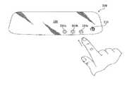
- FIG. 8shows an interior review minor assembly in accordance with one embodiment of the invention, where the mirror assembly is a touch screen.
- the mirror assembly 100includes, for example, a reflective element 105 , symbol 125 and cross-section 9 - 9 (shown in FIG. 9 ).
- the touch screenprovides the minor assembly 100 the ability to detect the touch or approach of an input device, such as a user's finger, pen or similar, at any location on the reflective element 105 (although it is understood that all or only a portion or multiple portions of the reflective element may be touch sensitive).
- FIG. 9shows a cross-sectional view 9 - 9 of the minor assembly of FIG. 8 in accordance with one embodiment of the invention.
- the minor assembly 100includes, for example, a housing 102 , a reflective element 105 , an illumination source 112 (in this embodiment depicted as a light source), a light guide 137 , a printed circuit board (PCB) 139 and a sensor 141 .
- the illumination source 112located behind the reflective element 105 , may also be touch sensitive. It is also appreciated that while the illumination source 112 is illustrated as a light source in the depicted embodiment, it may also form symbol 125 which is readily visible through the reflective element 105 .
- illumination source 112may be separate from the symbols, or part of the symbols.
- the illumination sourcesinclude a display device or element, such as illumination source 112 in the form of a LED, array of LEDs, multi-color LEDs, OLED and an array of OLEDs or multi-color display or similar and/or corresponding circuitry.
- the minor assembly 100may use any known touch sensitive or non-contact technology to determine input proximity to the reflective element 105 .
- indicators 110 a , 110 b and 110 cmay also act as inputs (i.e. the indicators may act as only and indicator or an input, or together as an indicator and an input).
- Indicators 110 a , 110 b and 110 care activated/deactivated when sensor 141 detects an input on or approaching the minor assembly 100 .
- illumination source 112upon activation of the indicators 110 a , 110 b and/or 110 c , emits light to light guide 137 .
- Light guide 137located behind the reflective element 105 , delivers light onto the rear side of reflective element 105 such that it is transmitted through the reflective element 105 at selected portions.
- the PCB 139(or alternatively circuit elements), responsible for operation, include touch controller circuitry and/or other circuitry or sensors or accessories depending on the desired application of the mirror assembly.
- the PCB 139may be located within the housing 102 , or at a location remote from the mirror assembly (such as within the vehicle or a location remote from the vehicle).
- the PCB 139may also include the HomelinkTM circuitry, or may be completely independent therefrom.
- the indicators 110 a , 110 b and 110 care displayed/visible (when activated) as a single LED, the indicator(s) may appear in any desired shape or pattern, and in any color. Additionally, the indicator(s) may have a brightness that varies with ambient light or is set to a desired level.
- Detecting of an input on or approaching the mirror assembly 100may include, but is not limited to, optical, capacitive, projected capacitive, projected capacitive, resistive, etc. or any other electro-optic and non-electro-optic technology.
- a light element(s)may be disposed at or near an optical sensor to gather and direct light toward the optical sensor.
- An input touching or approaching the screenmay change the light sensed at the optical sensor, thereby actuating portion(s) of the screen that correspond to the detection.
- a capacitive touch screen technologyfor example, the location of a touch on the reflective element 105 by an input is detected by sensing the current flow at multiple discrete locations around the reflective element 105 .
- a user's finger touching the screenconducts or draws current away from the screen.
- the amount of current that flows through various locations in proximity to the touched area of the screenis measured, and the location of the area on the screen touched, which may correspond for example to indicator 110 b , is determined.
- a signal corresponding to selection of the associated indicator 110 bmay then be generated accordingly.
- symbol 125may be illuminated to indicated that indicator 110 b has been selected.
- FIG. 10shows an exemplary touch sensitive interior review mirror assembly in accordance with one embodiment of the invention
- FIG. 11shows another exemplary touch sensitive interior review mirror assembly in accordance with one embodiment of the invention.
- a user inputi.e. finger
- FIG. 11shows user selection of a specific indicator, namely indicator 110 b .
- inputs 110 a , 110 b and 110 care illustrated as visible, they may be visible all the time or only when the illumination source (e.g.
- the indicators(s)can be lit (made visible) for a variable period of time based on another input from the vehicle, such as opening the door, turning on interior lights, starting the car, etc. which will allow the user to recognize this hidden feature.
- the method of activation and length of timecould be programmable by a user, such as from a vehicle message center.
- the inputsmay also be characters, numerals or symbols. The entire character, numeral or symbol or a portion thereof (such as the center of symbol 125 ) can be backlit by a single monochrome LED, use a multi-color display, or any other method known in the art.
- the three indicators 110 a , 110 b and 110 care only one embodiment. It is understood that any number of inputs and/or symbols may be used on the touch screen, and that any indicator (input) and/or symbol may be separate or the same elements (i.e. the symbol 125 may also act as an input and/or indicator and vice versa), as described above with reference to FIGS. 4-7 .
- tactile feedbackmay be provided when an indicator 110 a , 110 b , 110 c or a symbol 125 is selected (i.e. touched) by a user, for example as an indication that the indicator has been properly selected
- the tactile feedbackmay also indicate which of the indicators has been selected. For example, selection of a first indicator 110 a may illicit a single, short vibration, whereas selection of a second indicator 110 b may illicit two, short vibrations.
- selection of a symbol(s) 125may be indicated through the speakers in the vehicle or built into the mirror assembly itself.
Landscapes
- Engineering & Computer Science (AREA)
- Mechanical Engineering (AREA)
- Multimedia (AREA)
- Human Computer Interaction (AREA)
- General Engineering & Computer Science (AREA)
- Arrangements Of Lighting Devices For Vehicle Interiors, Mounting And Supporting Thereof, Circuits Therefore (AREA)
- Optical Elements Other Than Lenses (AREA)
Abstract
Description
Claims (29)
Priority Applications (3)
| Application Number | Priority Date | Filing Date | Title |
|---|---|---|---|
| US12/898,283US8643481B2 (en) | 2010-09-17 | 2010-10-05 | Interior rearview mirror assembly with integrated indicator symbol |
| PCT/US2011/054476WO2012050988A2 (en) | 2010-10-05 | 2011-10-01 | Interior rearview mirror assembly with integrated indicator symbol |
| US14/169,406US9841173B2 (en) | 2010-09-17 | 2014-01-31 | Interior rearview mirror assembly with integrated indicator symbol |
Applications Claiming Priority (2)
| Application Number | Priority Date | Filing Date | Title |
|---|---|---|---|
| US12/885,191US9180819B2 (en) | 2010-09-17 | 2010-09-17 | Interior rearview mirror assembly with integrated indicator symbol |
| US12/898,283US8643481B2 (en) | 2010-09-17 | 2010-10-05 | Interior rearview mirror assembly with integrated indicator symbol |
Related Parent Applications (1)
| Application Number | Title | Priority Date | Filing Date |
|---|---|---|---|
| US12/885,191Continuation-In-PartUS9180819B2 (en) | 2010-09-17 | 2010-09-17 | Interior rearview mirror assembly with integrated indicator symbol |
Related Child Applications (1)
| Application Number | Title | Priority Date | Filing Date |
|---|---|---|---|
| US14/169,406ContinuationUS9841173B2 (en) | 2010-09-17 | 2014-01-31 | Interior rearview mirror assembly with integrated indicator symbol |
Publications (2)
| Publication Number | Publication Date |
|---|---|
| US20120069444A1 US20120069444A1 (en) | 2012-03-22 |
| US8643481B2true US8643481B2 (en) | 2014-02-04 |
Family
ID=45938898
Family Applications (2)
| Application Number | Title | Priority Date | Filing Date |
|---|---|---|---|
| US12/898,283Active2032-03-16US8643481B2 (en) | 2010-09-17 | 2010-10-05 | Interior rearview mirror assembly with integrated indicator symbol |
| US14/169,406Active2030-10-20US9841173B2 (en) | 2010-09-17 | 2014-01-31 | Interior rearview mirror assembly with integrated indicator symbol |
Family Applications After (1)
| Application Number | Title | Priority Date | Filing Date |
|---|---|---|---|
| US14/169,406Active2030-10-20US9841173B2 (en) | 2010-09-17 | 2014-01-31 | Interior rearview mirror assembly with integrated indicator symbol |
Country Status (2)
| Country | Link |
|---|---|
| US (2) | US8643481B2 (en) |
| WO (1) | WO2012050988A2 (en) |
Cited By (15)
| Publication number | Priority date | Publication date | Assignee | Title |
|---|---|---|---|---|
| US20140146551A1 (en)* | 2010-09-17 | 2014-05-29 | Douglas C. Campbell | Interior rearview mirror assembly with integrated indicator symbol |
| US20150336506A1 (en)* | 2014-05-23 | 2015-11-26 | Hyundai Motor Company | Method of controlling button symbol of inside mirror |
| US9365315B2 (en)* | 2014-01-28 | 2016-06-14 | Omnicell, Inc. | Versatile lighting system for dispensing cabinets |
| US9576408B2 (en) | 2014-07-30 | 2017-02-21 | Gentex Corporation | Battery powered trainable remote garage door opener module |
| US9715772B2 (en) | 2013-11-15 | 2017-07-25 | Gentex Corporation | Internet-connected garage door control system |
| US10119694B2 (en)* | 2015-06-18 | 2018-11-06 | Mary L. Ellis | Door integrated lighted mirror system |
| US10137857B1 (en)* | 2017-08-22 | 2018-11-27 | Ford Global Technologies, Llc | Vehicle unlocking systems, devices, and methods |
| DE212017000226U1 (en) | 2016-10-05 | 2019-05-13 | Gentex Corporation | Vehicle-based remote control system |
| US10300889B2 (en) | 2017-09-08 | 2019-05-28 | Ford Global Technologies, Llc | Iris-detection alignment for vehicle feature activation |
| US11014532B2 (en)* | 2018-05-14 | 2021-05-25 | Gentex Corporation | Vehicle control module for smart home control system |
| US11024192B2 (en) | 2016-06-07 | 2021-06-01 | Gentex Corporation | Vehicle trainable transceiver for allowing cloud-based transfer of data between vehicles |
| US11411594B2 (en) | 2019-04-30 | 2022-08-09 | Gentex Corporation | Vehicle trainable transceiver having a programmable oscillator |
| US11470063B2 (en) | 2018-08-17 | 2022-10-11 | Gentex Corporation | Vehicle configurable transmitter for allowing cloud-based transfer of data between vehicles |
| US11745662B2 (en) | 2019-11-27 | 2023-09-05 | Unimicron Technology Corp. | Electrochromic mirror module |
| WO2025134054A1 (en)* | 2023-12-20 | 2025-06-26 | Gentex Corporation | Vehicle rearview assembly with through bezel infrared illumination and proximity sensor |
Families Citing this family (42)
| Publication number | Priority date | Publication date | Assignee | Title |
|---|---|---|---|---|
| US9134585B2 (en) | 2002-09-30 | 2015-09-15 | Gentex Corporation | Automotive rearview mirror with capacitive switches |
| US9346402B2 (en) | 2002-09-30 | 2016-05-24 | Gentex Corporation | Vehicular rearview mirror elements and assemblies incorporating these elements |
| US8169684B2 (en) | 2002-09-30 | 2012-05-01 | Gentex Corporation | Vehicular rearview mirror elements and assemblies incorporating these elements |
| US8004741B2 (en) | 2004-02-27 | 2011-08-23 | Gentex Corporation | Vehicular rearview mirror elements and assemblies incorporating these elements |
| US9056584B2 (en) | 2010-07-08 | 2015-06-16 | Gentex Corporation | Rearview assembly for a vehicle |
| US9316347B2 (en) | 2012-01-24 | 2016-04-19 | Gentex Corporation | Rearview assembly with interchangeable rearward viewing device |
| US8879139B2 (en) | 2012-04-24 | 2014-11-04 | Gentex Corporation | Display mirror assembly |
| EP3881723A1 (en)* | 2012-06-01 | 2021-09-22 | Pioneer Corporation | Device |
| US8864322B2 (en) | 2012-08-24 | 2014-10-21 | Gentex Corporation | Shaped rearview mirror assembly |
| US8970352B2 (en)* | 2012-10-23 | 2015-03-03 | GM Global Technology Operations LLC | Remote activated garage door opener functions via a graphical user interface in a vehicle |
| US9327648B2 (en) | 2013-01-04 | 2016-05-03 | Gentex Corporation | Rearview assembly with exposed carrier plate |
| WO2014110124A1 (en) | 2013-01-09 | 2014-07-17 | Gentex Corporation | Printed appliqué and method thereof |
| KR101992340B1 (en)* | 2013-03-27 | 2019-06-25 | 삼성디스플레이 주식회사 | Window and display device |
| US9031624B2 (en)* | 2013-08-07 | 2015-05-12 | Brian Ignomirello | Intelligent mirror |
| JP2016534915A (en) | 2013-09-24 | 2016-11-10 | ジェンテックス コーポレイション | Display mirror assembly |
| CN111994037A (en) | 2014-03-26 | 2020-11-27 | 麦格纳车镜美国有限公司 | Vehicle function control system using projected icons |
| US9694751B2 (en) | 2014-09-19 | 2017-07-04 | Gentex Corporation | Rearview assembly |
| WO2016073848A1 (en) | 2014-11-07 | 2016-05-12 | Gentex Corporation | Full display mirror actuator |
| US10071689B2 (en) | 2014-11-13 | 2018-09-11 | Gentex Corporation | Rearview mirror system with a display |
| US10131279B2 (en) | 2014-12-03 | 2018-11-20 | Gentex Corporation | Display mirror assembly with an RF shield bezel |
| USD746744S1 (en) | 2014-12-05 | 2016-01-05 | Gentex Corporation | Rearview device |
| JP2018513810A (en) | 2015-04-20 | 2018-05-31 | ジェンテックス コーポレイション | Rear view assembly with decoration |
| EP3297870B1 (en) | 2015-05-18 | 2020-02-05 | Gentex Corporation | Full display rearview device |
| WO2017075420A1 (en) | 2015-10-30 | 2017-05-04 | Gentex Corporation | Toggle paddle |
| CN108349436B (en) | 2015-10-30 | 2019-12-20 | 金泰克斯公司 | Rear-view device |
| US10760783B2 (en)* | 2015-12-09 | 2020-09-01 | Margaux Reynolds | Table with attached lamp and embedded touch controls |
| DE102016201882A1 (en)* | 2016-02-09 | 2017-08-10 | Bayerische Motoren Werke Aktiengesellschaft | Light module of a vehicle |
| KR102496913B1 (en) | 2016-03-24 | 2023-02-08 | 삼성디스플레이 주식회사 | Organic light emitting display device |
| USD845851S1 (en)* | 2016-03-31 | 2019-04-16 | Gentex Corporation | Rearview device |
| US10254634B2 (en)* | 2016-04-15 | 2019-04-09 | Panavision International, L.P. | Camera optical element having tactile indicator |
| USD817238S1 (en)* | 2016-04-29 | 2018-05-08 | Gentex Corporation | Rearview device |
| US10025138B2 (en) | 2016-06-06 | 2018-07-17 | Gentex Corporation | Illuminating display with light gathering structure |
| USD809984S1 (en) | 2016-12-07 | 2018-02-13 | Gentex Corporation | Rearview assembly |
| USD854473S1 (en) | 2016-12-16 | 2019-07-23 | Gentex Corporation | Rearview assembly |
| EP3339099A1 (en)* | 2016-12-22 | 2018-06-27 | Fico Mirrors S.A. | Rear view mirror for motor vehicles |
| CN106549660A (en)* | 2017-01-16 | 2017-03-29 | 福州丹诺西诚电子科技有限公司 | A car central control solid wood switch |
| CN106802743A (en)* | 2017-03-09 | 2017-06-06 | 东莞崧崴电子科技有限公司 | Contactor control device on mirror |
| US10602861B2 (en)* | 2018-07-03 | 2020-03-31 | Ksenia Meyers | Digital vanity mirror assembly |
| JP7162246B2 (en)* | 2018-11-22 | 2022-10-28 | パナソニックIpマネジメント株式会社 | input device |
| CN112455328A (en)* | 2020-12-09 | 2021-03-09 | 广州新晨汽车零部件有限公司 | Touch device for automobile atmosphere lamp and implementation method |
| US11646797B2 (en)* | 2021-03-31 | 2023-05-09 | Gentex Corporation | Integral communication access in trainable transceiver |
| WO2023130056A1 (en)* | 2021-12-30 | 2023-07-06 | Gentex Corporation | Rearview assembly |
Citations (14)
| Publication number | Priority date | Publication date | Assignee | Title |
|---|---|---|---|---|
| JPH01289725A (en) | 1988-05-17 | 1989-11-21 | Yazaki Corp | Display for vehicle |
| US5604644A (en) | 1993-12-21 | 1997-02-18 | Mekra Rangau Plastics Gmbh & Co. Kg | Rear-view mirror, in particular for trucks |
| US20050264891A1 (en)* | 2004-06-01 | 2005-12-01 | Uken John T | Mirror assembly for vehicle |
| US20060158351A1 (en) | 2004-12-31 | 2006-07-20 | Horng-Wen Lee | Integrated driving information displaying device for a vehicle |
| US7084859B1 (en) | 1992-09-18 | 2006-08-01 | Pryor Timothy R | Programmable tactile touch screen displays and man-machine interfaces for improved vehicle instrumentation and telematics |
| US7224324B2 (en)* | 2000-03-27 | 2007-05-29 | Donnelly Corporation | Interactive automotive rearvision system |
| US7488080B2 (en) | 1999-11-24 | 2009-02-10 | Donnelly Corporation | Information display system for a vehicle |
| US20090067032A1 (en) | 1994-05-05 | 2009-03-12 | Donnelly Corporation | Vehicular signal mirror |
| EP2042373A2 (en) | 2007-09-28 | 2009-04-01 | Murakami Corporation | Vehicle rear-view mirror |
| US20090115631A1 (en) | 2007-11-05 | 2009-05-07 | Magna Mirrors Of America, Inc. | Exterior mirror with indicator |
| US20090201690A1 (en) | 2008-02-07 | 2009-08-13 | Joseph Ivan Rodolph Boivin | Indicator display assembly for a vehicle rearview mirror |
| US20090243824A1 (en) | 2008-03-31 | 2009-10-01 | Magna Mirrors Of America, Inc. | Interior rearview mirror system |
| US20090251913A1 (en) | 2008-04-03 | 2009-10-08 | Visiocorp Patents S.A.R.L. | Plastic Glass Interior Mirror With Illumination |
| US20100097469A1 (en) | 2008-10-16 | 2010-04-22 | Magna Mirrors Of America, Inc. | Interior mirror assembly with display |
Family Cites Families (33)
| Publication number | Priority date | Publication date | Assignee | Title |
|---|---|---|---|---|
| US5174643A (en)* | 1988-05-18 | 1992-12-29 | Priesemuth W | Electric light switching arrangement for illuminating the interior of a motor vehicle |
| US5555172A (en)* | 1994-08-22 | 1996-09-10 | Prince Corporation | User interface for controlling accessories and entering data in a vehicle |
| US5786772A (en)* | 1996-03-22 | 1998-07-28 | Donnelly Corporation | Vehicle blind spot detection display system |
| US6028537A (en)* | 1996-06-14 | 2000-02-22 | Prince Corporation | Vehicle communication and remote control system |
| US6592230B2 (en)* | 1997-10-16 | 2003-07-15 | Holland Hitch Company | Truck rearview mirror assembly having a display for displaying trailer coupling status information |
| US6124647A (en)* | 1998-12-16 | 2000-09-26 | Donnelly Corporation | Information display in a rearview mirror |
| GB9903189D0 (en)* | 1999-02-13 | 1999-04-07 | Rover Group | A user interface unit for a vehicle |
| US6614579B2 (en)* | 1999-10-22 | 2003-09-02 | Gentex Corporation | Proximity switch and vehicle rearview mirror assembly incorporating the same and having a transparent housing |
| US6803906B1 (en)* | 2000-07-05 | 2004-10-12 | Smart Technologies, Inc. | Passive touch system and method of detecting user input |
| US7255451B2 (en)* | 2002-09-20 | 2007-08-14 | Donnelly Corporation | Electro-optic mirror cell |
| JP4081287B2 (en)* | 2002-04-11 | 2008-04-23 | Kpe株式会社 | Game machine |
| WO2004103772A2 (en)* | 2003-05-19 | 2004-12-02 | Donnelly Corporation | Mirror assembly for vehicle |
| US7253723B2 (en)* | 2003-05-19 | 2007-08-07 | Donnelly Corporation | Mirror assembly |
| KR20060091310A (en)* | 2003-09-30 | 2006-08-18 | 코닌클리케 필립스 일렉트로닉스 엔.브이. | Gestures that define the position, size, and / or content of the content window on the display |
| US7308341B2 (en)* | 2003-10-14 | 2007-12-11 | Donnelly Corporation | Vehicle communication system |
| EP1697827B1 (en)* | 2003-11-18 | 2017-01-04 | Johnson Controls Technology Company | Reconfigurable user interface |
| US7488099B2 (en)* | 2004-04-16 | 2009-02-10 | Gentex Corporation | Rearview mirror light |
| US7728316B2 (en)* | 2005-09-30 | 2010-06-01 | Apple Inc. | Integrated proximity sensor and light sensor |
| US7485843B2 (en)* | 2006-03-31 | 2009-02-03 | Masstech Group Inc. | Touch/proximity-sensing using reflective optical sensor and a light pipe for specularly reflecting light |
| US20080147321A1 (en)* | 2006-12-18 | 2008-06-19 | Damian Howard | Integrating Navigation Systems |
| US7817020B2 (en)* | 2006-10-17 | 2010-10-19 | Gentex Corporation | Optical user interface system for automotive modules |
| US20080215240A1 (en)* | 2006-12-18 | 2008-09-04 | Damian Howard | Integrating User Interfaces |
| US20090096937A1 (en)* | 2007-08-16 | 2009-04-16 | Bauer Frederick T | Vehicle Rearview Assembly Including a Display for Displaying Video Captured by a Camera and User Instructions |
| US7868750B2 (en)* | 2008-02-06 | 2011-01-11 | Ford Global Technologies, Llc | System and method for controlling a safety restraint status based on driver status |
| US20100007463A1 (en)* | 2008-07-09 | 2010-01-14 | Magna Mirrors Of America, Inc. | Vehicle handle with control circuitry |
| US8704653B2 (en)* | 2009-04-02 | 2014-04-22 | GM Global Technology Operations LLC | Enhanced road vision on full windshield head-up display |
| CN102648113B (en)* | 2009-10-07 | 2015-05-27 | 麦格纳镜片美国有限公司 | Frameless interior rearview mirror assembly |
| CN102096526B (en)* | 2009-12-15 | 2015-11-25 | 乐金显示有限公司 | Optical sensing unit, display module and display device using optical sensing unit |
| US8519860B2 (en)* | 2010-04-09 | 2013-08-27 | Weather Decision Technologies | Multimedia alerting |
| US8643481B2 (en)* | 2010-09-17 | 2014-02-04 | Johnson Controls Technology Company | Interior rearview mirror assembly with integrated indicator symbol |
| EP2758944B1 (en)* | 2011-09-23 | 2019-10-30 | Gentex Corporation | Systems and methods for rear view mirror displays |
| US8886399B2 (en)* | 2013-03-15 | 2014-11-11 | Honda Motor Co., Ltd. | System and method for controlling a vehicle user interface based on gesture angle |
| KR101575477B1 (en)* | 2014-05-23 | 2015-12-07 | 현대자동차주식회사 | Control method for button symbol of inside mirror |
- 2010
- 2010-10-05USUS12/898,283patent/US8643481B2/enactiveActive
- 2011
- 2011-10-01WOPCT/US2011/054476patent/WO2012050988A2/enactiveApplication Filing
- 2014
- 2014-01-31USUS14/169,406patent/US9841173B2/enactiveActive
Patent Citations (14)
| Publication number | Priority date | Publication date | Assignee | Title |
|---|---|---|---|---|
| JPH01289725A (en) | 1988-05-17 | 1989-11-21 | Yazaki Corp | Display for vehicle |
| US7084859B1 (en) | 1992-09-18 | 2006-08-01 | Pryor Timothy R | Programmable tactile touch screen displays and man-machine interfaces for improved vehicle instrumentation and telematics |
| US5604644A (en) | 1993-12-21 | 1997-02-18 | Mekra Rangau Plastics Gmbh & Co. Kg | Rear-view mirror, in particular for trucks |
| US20090067032A1 (en) | 1994-05-05 | 2009-03-12 | Donnelly Corporation | Vehicular signal mirror |
| US7488080B2 (en) | 1999-11-24 | 2009-02-10 | Donnelly Corporation | Information display system for a vehicle |
| US7224324B2 (en)* | 2000-03-27 | 2007-05-29 | Donnelly Corporation | Interactive automotive rearvision system |
| US20050264891A1 (en)* | 2004-06-01 | 2005-12-01 | Uken John T | Mirror assembly for vehicle |
| US20060158351A1 (en) | 2004-12-31 | 2006-07-20 | Horng-Wen Lee | Integrated driving information displaying device for a vehicle |
| EP2042373A2 (en) | 2007-09-28 | 2009-04-01 | Murakami Corporation | Vehicle rear-view mirror |
| US20090115631A1 (en) | 2007-11-05 | 2009-05-07 | Magna Mirrors Of America, Inc. | Exterior mirror with indicator |
| US20090201690A1 (en) | 2008-02-07 | 2009-08-13 | Joseph Ivan Rodolph Boivin | Indicator display assembly for a vehicle rearview mirror |
| US20090243824A1 (en) | 2008-03-31 | 2009-10-01 | Magna Mirrors Of America, Inc. | Interior rearview mirror system |
| US20090251913A1 (en) | 2008-04-03 | 2009-10-08 | Visiocorp Patents S.A.R.L. | Plastic Glass Interior Mirror With Illumination |
| US20100097469A1 (en) | 2008-10-16 | 2010-04-22 | Magna Mirrors Of America, Inc. | Interior mirror assembly with display |
Cited By (20)
| Publication number | Priority date | Publication date | Assignee | Title |
|---|---|---|---|---|
| US9841173B2 (en)* | 2010-09-17 | 2017-12-12 | Gentex Corporation | Interior rearview mirror assembly with integrated indicator symbol |
| US20140146551A1 (en)* | 2010-09-17 | 2014-05-29 | Douglas C. Campbell | Interior rearview mirror assembly with integrated indicator symbol |
| US10339734B2 (en) | 2013-11-15 | 2019-07-02 | Gentex Corporation | Internet-connected garage door control system |
| US9715772B2 (en) | 2013-11-15 | 2017-07-25 | Gentex Corporation | Internet-connected garage door control system |
| US9365315B2 (en)* | 2014-01-28 | 2016-06-14 | Omnicell, Inc. | Versatile lighting system for dispensing cabinets |
| US20150336506A1 (en)* | 2014-05-23 | 2015-11-26 | Hyundai Motor Company | Method of controlling button symbol of inside mirror |
| US9663029B2 (en)* | 2014-05-23 | 2017-05-30 | Hyundai Motor Company | Method of controlling button symbol of inside mirror |
| US9576408B2 (en) | 2014-07-30 | 2017-02-21 | Gentex Corporation | Battery powered trainable remote garage door opener module |
| US10134213B2 (en) | 2014-07-30 | 2018-11-20 | Gentex Corporation | Battery powered trainable remote garage door opener module |
| US10119694B2 (en)* | 2015-06-18 | 2018-11-06 | Mary L. Ellis | Door integrated lighted mirror system |
| US11024192B2 (en) | 2016-06-07 | 2021-06-01 | Gentex Corporation | Vehicle trainable transceiver for allowing cloud-based transfer of data between vehicles |
| DE212017000226U1 (en) | 2016-10-05 | 2019-05-13 | Gentex Corporation | Vehicle-based remote control system |
| US10137857B1 (en)* | 2017-08-22 | 2018-11-27 | Ford Global Technologies, Llc | Vehicle unlocking systems, devices, and methods |
| US10300889B2 (en) | 2017-09-08 | 2019-05-28 | Ford Global Technologies, Llc | Iris-detection alignment for vehicle feature activation |
| US11167725B2 (en) | 2017-09-08 | 2021-11-09 | Ford Global Technologies, Llc | Iris-detection alignment for vehicle feature activation |
| US11014532B2 (en)* | 2018-05-14 | 2021-05-25 | Gentex Corporation | Vehicle control module for smart home control system |
| US11470063B2 (en) | 2018-08-17 | 2022-10-11 | Gentex Corporation | Vehicle configurable transmitter for allowing cloud-based transfer of data between vehicles |
| US11411594B2 (en) | 2019-04-30 | 2022-08-09 | Gentex Corporation | Vehicle trainable transceiver having a programmable oscillator |
| US11745662B2 (en) | 2019-11-27 | 2023-09-05 | Unimicron Technology Corp. | Electrochromic mirror module |
| WO2025134054A1 (en)* | 2023-12-20 | 2025-06-26 | Gentex Corporation | Vehicle rearview assembly with through bezel infrared illumination and proximity sensor |
Also Published As
| Publication number | Publication date |
|---|---|
| US20120069444A1 (en) | 2012-03-22 |
| WO2012050988A3 (en) | 2012-07-26 |
| US9841173B2 (en) | 2017-12-12 |
| US20140146551A1 (en) | 2014-05-29 |
| WO2012050988A2 (en) | 2012-04-19 |
Similar Documents
| Publication | Publication Date | Title |
|---|---|---|
| US8643481B2 (en) | Interior rearview mirror assembly with integrated indicator symbol | |
| JP4292647B2 (en) | Compound display device | |
| EP2084686B1 (en) | Optical user interface system for automotive modules | |
| US6420800B1 (en) | Rearview mirror with buttons incorporating display | |
| US8847897B2 (en) | Touch-operating input device and electronic device equipped with the same | |
| CN210162053U (en) | Input keypad assembly on a vehicle | |
| KR20120015349A (en) | User interface with circular optical waveguided ring with adaptive shape according to function | |
| CN105814526B (en) | Display operating area with modulated light | |
| KR20070073122A (en) | Control button for refrigerator | |
| US20100225499A1 (en) | Device for inputting control commands | |
| US7098895B2 (en) | Optical trackball device and electronic apparatus | |
| CN112930276B (en) | Surface-illuminated decorative element with optically activated symbol body | |
| US9180819B2 (en) | Interior rearview mirror assembly with integrated indicator symbol | |
| CN213734612U (en) | Vehicle operation panel | |
| JP2007080808A (en) | Capacitance switch, automotive electrical component, vehicle meter and interior lighting device | |
| KR102034114B1 (en) | Transparent touch screen and doorlock having the touch screen | |
| EP4003788B1 (en) | Interior rearview device with human machine interface and vehicle therewith | |
| JP2020204868A (en) | Display device | |
| KR100918211B1 (en) | Dimming control switch and its control method | |
| CN114537143B (en) | Vehicle operation panel | |
| US11646797B2 (en) | Integral communication access in trainable transceiver | |
| US11600732B2 (en) | Variable transmittance window assembly | |
| KR101262599B1 (en) | Apparatus for controlling mood lamp using touch slide switch | |
| US20230377815A1 (en) | All-in-one-security system controller with tactile input | |
| JP3067753B1 (en) | Taxi meter |
Legal Events
| Date | Code | Title | Description |
|---|---|---|---|
| AS | Assignment | Owner name:JOHNSON CONTROLS TECHNOLOGY COMPANY, MICHIGAN Free format text:ASSIGNMENT OF ASSIGNORS INTEREST;ASSIGNORS:CAMPBELL, DOUGLAS C.;EICH, RODGER WILLIAM;REEL/FRAME:025094/0368 Effective date:20101005 | |
| STCF | Information on status: patent grant | Free format text:PATENTED CASE | |
| AS | Assignment | Owner name:GENTEX CORPORATION, MICHIGAN Free format text:ASSIGNMENT OF ASSIGNORS INTEREST;ASSIGNOR:GENTEX CORPORATION;REEL/FRAME:032471/0695 Effective date:20130927 | |
| AS | Assignment | Owner name:GENTEX CORPORATION, MICHIGAN Free format text:CORRECTIVE ASSIGNMENT TO CORRECT THE PATENT # 5703941 IS INCORRECT AND SHOULD BE 6703941. PATENT # 6330569 IS INCORRECT AND SHOULD BE 8330569. PREVIOUSLY RECORDED ON REEL 032471 FRAME 0695. ASSIGNOR(S) HEREBY CONFIRMS THE ASSIGNMENT OF ASSIGNORS INTEREST;ASSIGNOR:GENTEX CORPORATION;REEL/FRAME:032514/0564 Effective date:20130927 | |
| AS | Assignment | Owner name:GENTEX CORPORATION, MICHIGAN Free format text:CORRECTIVE ASSIGNMENT TO CORRECT THE ASSIGNOR, SHOULD BE JOHNSON CONTROLS TECHNOLOGY COMPANY. ADDITIONAL CORRECTIVE ASSIGNMENT RECORDED @ 032514/0564. PREVIOUSLY RECORDED ON REEL 032471 FRAME 0695. ASSIGNOR(S) HEREBY CONFIRMS THE ASSIGNMENT OF ASSIGNORS INTEREST;ASSIGNOR:JOHNSON CONTROLS TECHNOLOGY COMPANY;REEL/FRAME:032621/0757 Effective date:20130927 | |
| AS | Assignment | Owner name:GENTEX CORPORATION, MICHIGAN Free format text:CORRECTIVE ASSIGNMENT TO CORRECT THE ASSIGNOR, IT SHOULD BE JOHNSON CONTROLS TECHNOLOGY COMPANY. PREVIOUSLY RECORDED ON REEL 032514 FRAME 0564. ASSIGNOR(S) HEREBY CONFIRMS THE ASSIGNMENT OF ASSIGNORS INTEREST;ASSIGNOR:JOHNSON CONTROLS TECHNOLOGY COMPANY;REEL/FRAME:032664/0688 Effective date:20130927 | |
| CC | Certificate of correction | ||
| FPAY | Fee payment | Year of fee payment:4 | |
| MAFP | Maintenance fee payment | Free format text:PAYMENT OF MAINTENANCE FEE, 8TH YEAR, LARGE ENTITY (ORIGINAL EVENT CODE: M1552); ENTITY STATUS OF PATENT OWNER: LARGE ENTITY Year of fee payment:8 | |
| MAFP | Maintenance fee payment | Free format text:PAYMENT OF MAINTENANCE FEE, 12TH YEAR, LARGE ENTITY (ORIGINAL EVENT CODE: M1553); ENTITY STATUS OF PATENT OWNER: LARGE ENTITY Year of fee payment:12 |