US8642900B2 - Modular electromagnetically shielded enclosure - Google Patents
Modular electromagnetically shielded enclosureDownload PDFInfo
- Publication number
- US8642900B2 US8642900B2US12/906,875US90687510AUS8642900B2US 8642900 B2US8642900 B2US 8642900B2US 90687510 AUS90687510 AUS 90687510AUS 8642900 B2US8642900 B2US 8642900B2
- Authority
- US
- United States
- Prior art keywords
- enclosure
- shells
- interior volume
- continuously
- shell
- Prior art date
- Legal status (The legal status is an assumption and is not a legal conclusion. Google has not performed a legal analysis and makes no representation as to the accuracy of the status listed.)
- Active, expires
Links
Images


Classifications
- H—ELECTRICITY
- H05—ELECTRIC TECHNIQUES NOT OTHERWISE PROVIDED FOR
- H05K—PRINTED CIRCUITS; CASINGS OR CONSTRUCTIONAL DETAILS OF ELECTRIC APPARATUS; MANUFACTURE OF ASSEMBLAGES OF ELECTRICAL COMPONENTS
- H05K9/00—Screening of apparatus or components against electric or magnetic fields
- H05K9/0001—Rooms or chambers
- H—ELECTRICITY
- H05—ELECTRIC TECHNIQUES NOT OTHERWISE PROVIDED FOR
- H05K—PRINTED CIRCUITS; CASINGS OR CONSTRUCTIONAL DETAILS OF ELECTRIC APPARATUS; MANUFACTURE OF ASSEMBLAGES OF ELECTRICAL COMPONENTS
- H05K7/00—Constructional details common to different types of electric apparatus
- H05K7/14—Mounting supporting structure in casing or on frame or rack
- H05K7/1485—Servers; Data center rooms, e.g. 19-inch computer racks
- H05K7/1497—Rooms for data centers; Shipping containers therefor
- Y—GENERAL TAGGING OF NEW TECHNOLOGICAL DEVELOPMENTS; GENERAL TAGGING OF CROSS-SECTIONAL TECHNOLOGIES SPANNING OVER SEVERAL SECTIONS OF THE IPC; TECHNICAL SUBJECTS COVERED BY FORMER USPC CROSS-REFERENCE ART COLLECTIONS [XRACs] AND DIGESTS
- Y10—TECHNICAL SUBJECTS COVERED BY FORMER USPC
- Y10T—TECHNICAL SUBJECTS COVERED BY FORMER US CLASSIFICATION
- Y10T29/00—Metal working
- Y10T29/49—Method of mechanical manufacture
- Y10T29/49002—Electrical device making
Definitions
- the present disclosurerelates to enclosures providing protection from electromagnetic fields.
- the present disclosurerelates to a modular electromagnetically shielded enclosure, or to a system of electromagnetically shielded enclosures.
- Exposure to electromagnetic fieldscan cause interference or damage to such electronic equipment, causing that equipment to malfunction or rendering it nonoperational.
- These electronicsare susceptible to being disrupted or damaged by electromagnetic interference, such as an electromagnetic pulse (generally characterized by frequencies between 14 kHz and 1 GHz) or intentional electromagnetic interference (generally characterized by frequencies between 10 MHz and 10 GHz) (EMP/IEMI) event.
- electromagnetic interferencesuch as an electromagnetic pulse (generally characterized by frequencies between 14 kHz and 1 GHz) or intentional electromagnetic interference (generally characterized by frequencies between 10 MHz and 10 GHz) (EMP/IEMI) event.
- EMP/IEMIintentional electromagnetic interference
- These electromagnetic eventsare capable of producing electromagnetic environments of much higher intensity than current electronic equipment is designed to operate in. Environments requiring the shielding of sensitive electronic equipment have not been considered in current standards for protection against electromagnetic interference and protection in these environments requires shielding sensitive electronic equipment in ways that have not been adopted in the industry related to electromagnetic compatibility is required.
- HEMPhigh altitude nuclear electromagnetic pulse
- Standardsare written toward protecting facilities, and physically substantial shielding is used in such construction.
- Electromagnetic shieldinghas been previously used to address discrete circumstances. Such examples are magnetic resonance imaging (MRI) rooms, shielding rooms used to test equipment and electromagnetic standards, shielding used in research facilities to protect sensitive equipment from interference.
- MRImagnetic resonance imaging
- shielding rooms used to test equipment and electromagnetic standardsshielding used in research facilities to protect sensitive equipment from interference.
- a shield against EMP/IEMI eventscan be constructed making a solid electromagnetically conductive enclosure (sometimes called a “Faraday cage”).
- Faraday cagesolid electromagnetically conductive enclosure
- These enclosureslack practical applicability, however, as any attempt to access the interior of the enclosure disrupts the shielding effect and exposes any sensitive equipment housed in the enclosure to a timely EMP/IEMI event.
- Existing and planned data centers using such enclosurestend to be individually engineered in that the physical layout of the spaces is different from data center to data center. This type of approach leads to high design and construction costs.
- existing methods for protecting sensitive electronics from electromagnetic interferenceare designed with a narrow range of applicability in mind and do not cover the entire range of potential EMP/IEMI threats.
- the enclosures of the present disclosureproposed are an engineered system that can be built at remote locations, hauled, and installed at the data center location with relative ease, efficiency, and cost effectiveness. Moreover, the enclosures of the present disclosure provide protection from a wide range of EMP/IEMI threats. Additionally, large-scale data centers typically used to perform operations in a number of industries are not currently designed with these concerns in mind, and are constructed in such a way to make modifications, whether for protection, expansion, or other reasons, extremely difficult.
- an enclosure providing shielding from EMP/IEMI eventsincludes a continuously-welded shell, at least one two-door sally port, and at least one point of grounding.
- the continuously-welded shell and each door of the two-door sally portare constructed from electromagnetically conductive materials.
- Such an enclosurepermits access to the interior of the enclosure without disrupting the continuity of protection against potentially harmful EMP/IEMI events.
- resourcessuch as air, water, electricity, and electronic communications can be imported and exported into or out of the enclosure.
- an enclosure as described abovethat can be used as a modular assembly of independent, interconnected shells.
- These shellscan be connected using any of a variety of known electromagnetically-conductive connections, provided that all joints of the connection are continuously welded to provide continuous electromagnetic shielding.
- Resourcessuch as air, water, electricity, and electronic communications can be shared between interconnected shells through these connections or through other, independent fixtures.
- a modular enclosure of this descriptioncan house equipment such as generators, chillers, electronic data storage servers, as well as a variety of sensors and detectors to make the enclosure completely self-sufficient.
- an enclosure as described abovethat can be used as a modular assembly of independent, interconnected shells.
- These shellscan be connected using any of a variety of known electromagnetically-conductive connections, provided that all joints of the connection are continuously welded to provide continuous electromagnetic shielding. Resources such as air, water, electricity, and electronic communications can be shared between interconnected shells through these connections or through other, independent fixtures.
- the enclosureincludes at least one shell in which computing equipment operates 424 , at least one shell in which power delivery equipment 410 operates, at least one shell in which cooling equipment 412 operates, and at least one shell in which an electric generator 416 operates.
- the enclosuremay also include at least one external supplemental cooling apparatus 414 for cooling liquids or gases that is not electromagnetically shielded but is configured to operate without disruption during and after an EMP/IEMI event.
- the enclosurefurther includes at least one environmental sensor 418 , such as a smoke detector, to monitor conditions within the enclosure.
- a method of manufacturing an electromagnetically shielded enclosureincludes providing an electromagnetically conductive top, an electromagnetically conductive bottom, and a plurality of electromagnetically side walls. The method further includes positioning each of these elements so that they enclose an interior volume. The method further includes the step of continuously welding all seams formed between these elements. The method also includes a step of providing a sally port constructed of electromagnetically conductive material including a first door constructed from electromagnetically conductive material and a second door constructed from electromagnetically conductive materials. The method further includes the step of positioning the sally port so that at either the first or second door allows access to the interior volume of the enclosure. The method further includes at least one point of ground electrically connecting the enclosure to a reference ground.
- Enclosures built according to the present disclosureprovide shielding against electromagnetic shielding across a wide range of frequencies. Moreover, enclosures build according to the present disclosure are easily transported to the site of installation and can be easily arranged to suit the needs of a variety of applications by limiting engineering and construction costs.
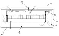
- FIG. 1is an overhead line drawing of an electromagnetically shielded enclosure according to an example embodiment of the present disclosure
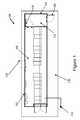
- FIG. 2is a perspective view of the electromagnetically shielded enclosure shown in FIG. 1 ;
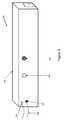
- FIG. 3is a perspective view of the electromagnetically shielded enclosure shown in FIG. 1 ;
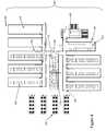
- FIG. 4is an overhead line drawing of a modular, electromagnetically shielded enclosure according to an example embodiment of the present disclosure
- FIG. 5Ais an overhead line drawing of a connection between two continuously-welded shells forming a portion of a modular, electromagnetically shielded enclosure
- FIG. 5Bis an overhead line drawing of a connection between two continuously-welded shells forming a portion of a modular, electromagnetically shielded enclosure.
- FIG. 6is a perspective view of a support mechanism forming a portion of a modular, electromagnetically shielded enclosure.
- the present disclosurerelates to an electromagnetically shielded enclosure, and in particular an enclosure shielded against EMP/IEMI events.
- the electromagnetically shielded enclosures of the present disclosureare configured to specifically protect against signals having a frequency between 14 kHz and 10 GHz, and having high electrical field (e.g., in excess of 100,000 Volts/meter).
- the electromagnetically shielded enclosureis made from a number of portable units, forming a modular enclosure. Even in such arrangements, connections between individual modules are constructed to retain the electromagnetic shielding of each individual module.
- An enclosure built according to the present disclosureprovides spatially- and temporally-continuous electromagnetic shielding while allowing access to an electronic instruments operating within the enclosure.
- An enclosure built according to the present disclosurealso provides modularity, allowing expansion of the enclosure with relative ease.
- an electromagnetically shielded enclosure 100is provided.
- the enclosureincludes a shell 102 .
- the shellmay take any shape, but must surround an interior volume 104 continuously in all directions.
- the shellincludes a top 202 , a bottom 204 , and four side walls 206 .
- the top 202can include a pitched roof, or otherwise be altered in shape.
- the shell 102may take any size. In various embodiments, the shell 102 is sized to allow transportation via flatbed truck to a desired location. In one embodiment, the interior volume 104 is sized to receive electronic equipment and allow human entry. In another embodiment, the shell 102 is 12 feet wide, 49 feet long, and 10 feet 6 inches tall.
- the shell 102can be constructed from any electromagnetically conductive materials.
- the electromagnetically conductive materialis steel plate, for instance 1 ⁇ 4-inch thick steel plate.
- the electromagnetically conductive materialmay be aluminum, copper, or any other electromagnetically conductive material or combination of materials. Any joints or seams formed at the intersection of two or more pieces of these construction materials must be continuously welded to provide for a complete electromagnetic shield.
- the enclosurealso includes a sally port 106 that is located at least partially within the shell 102 .
- the sally portincludes a first door 108 and a second door 110 .
- the sally portdefines a secondary interior volume 112 within the shell 102 and includes an intermediate shielded interior volume sized to allow human entry through one of the first 108 and second 110 doors.
- To provide continuous electromagnetic shieldingat least one of the first door 108 and second door 110 is closed at all times.
- Each of the first door 108 and the second door 110is constructed from electromagnetically conductive materials.
- the electromagnetically conductive materialis steel, but alternative materials, such as aluminum, copper, or any other electromagnetically conductive material or combination of any such materials, may be used. Doors appropriate for use in an electromagnetically shielded enclosure as described are commercially available.
- the enclosuremust be suitably grounded. In one embodiment, the enclosure is grounded at a single point. In another embodiment, the enclosure is grounded at multiple points. All points of grounding 114 must be electrically connected to the shell 102 . In order to ensure that the enclosure remains grounded at desired points, the shell 102 must be separated from the ground by a non-electromagnetically conductive spacer 116 .
- the spacermay be a neoprene pad, but other appropriate spacers may be used.
- the spacer 116is a flexible pad that allows physical movement related to expansion and contraction caused by temperature extremes found in some climates. In one embodiment, the spacer 116 also permits anchoring of the modules in a manner that prevents compromise of the desired points of ground by use of conductive fasteners.
- the enclosuremay include an emergency exit 118 that is constructed of the same materials as the doors of the sally port 106 described above. When closed, the emergency exit 118 will provide continuous electromagnetic shielding, but shielding will be disrupted when the emergency exit is opened.
- the shell 102includes a top 202 , a bottom 204 , and a plurality of side walls 206 enclosing interior volume 104 .
- each seam 208 joining the side walls 206 , the top 202 , and the bottom 206must be continuously welded to ensure complete electromagnetic shielding.
- the electromagnetically shielded enclosure described abovemay be constructed by providing a top, bottom, and plurality of side walls as described above and positioning these elements to form a shell with an interior volume.
- the seams formed between the top, bottom, and plurality of side wallsmust be continuously welded along their entire lengths to ensure proper electromagnetic shielding.
- a sally portcan be incorporated into the enclosure by providing a two-door sally port as described above and positioning the sally port so that one door allows access to the interior volume of the shell.
- the enclosuremust then be grounded by providing at least one point of grounding electrically connecting the shell to the reference ground.
- Air exchange into and out of the enclosure 100by providing a electromagnetically shielded vent 302 that penetrates shell 102 .
- the seams between the shell 102 and the shielded vent 302are continuously welded to ensure continuous protection.
- mechanical attachment of vent 302 to the shell 102 and the use of an electromagnetically conductive gasketare disclosed.
- the vent 302can include an opening that is guarded using any appropriate waveguide beyond cutoff that will sufficiently shield against EMP/IEMI threats.
- the ventincludes a waveguide beyond cutoff configured to filter electromagnetic frequencies between approximately 14 kHz and 10 GHz.
- the vent 302includes a waveguide beyond cutoff with individual cells having a diameter of 1 inch or smaller configured for a cutoff frequency of 10 GHz with minimum attenuation of 80 dB at this frequency.
- the dimensions of the waveguidesinclude a cell diameter of 1 ⁇ 8 inch and a thickness of 1 inch.
- Electricitymay also be imported into the enclosure 100 through use of an appropriate electrical power filter 304 extending from external to the electromagnetic shielded enclosure 100 into the interior volume.
- the electrical power filter 304may then be used to deliver power to electronic equipment held within the interior volume. Protection against power surges such as those caused by EMP or IEMI may be provided by the power filter 304 .
- a number of commercially-available power filtersmay be used.
- the power filter 304is configured to filter electromagnetic signals carried on the electrical conductor between approximately 14 kHz and 10 GHz.
- the seams between the shell 102 and the power filter 104are continuously welded to ensure continuous protection.
- mechanical attachment of power filter 304 to the shell 102 and the use of an electromagnetically conductive gasketare disclosed. The seams between the shell 102 and the power filter 304 must be continuously welded or gasketed to ensure continuous protection.
- Electronic communicationsmay be imported into the enclosure through use of an appropriate communicative connection 308 extending from external to the electromagnetic shielded enclosure 100 into the interior volume.
- the communicative connection 308may, in one embodiment, be a fiber optic cable.
- a fiber-optic cablemay be routed through a waveguide beyond cutoff 310 . Any suitable fiber-optic waveguide may be used, but in one embodiment the fiber-optic waveguide 310 is configured to filter electromagnetic frequencies below 10 GHz.
- Filtered conductive penetrationsmay be imported into the enclosure through use of an electrical filter 306 .
- Any acceptable filter 306may be used.
- the filter 306is configured to filter electromagnetic frequencies between 14 kHz and 10 GHz with 80 dB of attenuation at these frequencies.
- the seams between the filter 306 and the shell 102are continuously welded to ensure continuous protection.
- mechanical attachment of filter 306 to the shell 102 and the use of an electromagnetically conductive gasketare disclosed. The seams between the shell 102 and the filter 306 must be continuously welded or gasketed to ensure continuous protection.
- fixturessuch as the shielded vent 302 , electrical conduit 304 , and communicative connection 308 may be configured to connect the shielded enclosure 100 to another shielded enclosure.
- Such configurationpermits practical expansion of the total electromagnetically-shielded interior volume without compromising protection against EMP/IEMI events.
- the present disclosurealso contemplates a modular, electromagnetically shielded enclosure that may be used to form an electromagnetically shielded data center.
- a modular, electromagnetically shielded enclosure 400is shown.
- the modular enclosure 400is made up of a plurality of continuously-welded shells 402 constructed as described above. Each shell 402 is self-contained but interconnected with at least one other shell.
- the connections 404 between each of the shellsare each constructed from electromagnetically conductive materials. In one embodiment these connections are constructed from steel, but other conductive materials, such as aluminum, copper, and any other electromagnetically conductive material may be used.
- the shells 402are joined with connections 404 that are electromagnetically conductive and continuous.
- the connection 404 between the modulesis a continuously-welded common corridor that provides access to each of the shells 402 and permits the transport of resources between each of the shells 402 .
- the connection 404is a continuously welded conduit providing only for the exchange of resources.
- the connection 404is located at one end of each shell 402 , but other configurations are possible. For instance, a common connection 404 may run through the middle of multiple shells 402 .
- the modular enclosure 400includes at least one sally port 406 located at least partially within one of the plurality of continuously welded shells 402 .
- the sally portis constructed as described above and is constructed from electromagnetically conductive materials.
- the sally portis constructed from steel, but other conductive materials, such as aluminum and copper may be used.
- a variety of electronic equipmentmay be housed within the modular, electromagnetically shielded enclosure 400 .
- computing equipment 408may be housed within the interior volume of any of the continuously welded shells 402 .
- power delivery equipment 410may be operated within the interior volume of at least one of the plurality of shells 402 .
- the power delivery equipment 410may be configured to deliver power to the computing equipment 408 .
- Any acceptable power delivery equipment 410may be used.
- cooling equipment 412may be operated at least partially within the interior volume of at least one of the plurality of shells 402 .
- the cooling equipment 412may be configured to circulate cooled fluid throughout the interior volumes of each of the plurality of shells 402 . Any acceptable cooling equipment 412 may be used.
- Other equipment, such as an electrical generator 416 and/or sensitive instrumentsmay be housed in interior volume of one of the shells 402 .
- a modular enclosure 400 like that shown in FIG. 4may also include support shells 419 dedicated to support the equipment operating within other shells.
- these support shells 419are used as living quarters, but other uses are contemplated.
- the modular systemis constructed so that individual users have access only to specific shells, for instance through secured doors, for increased security or separation of computer equipment.
- an electromagnetically shielded enclosureincluding more than one shell (e.g., enclosure 400 )
- different shellscan be used to house different categories of electronic equipment.
- one shellcould have its interior volume dedicated to storage of computing equipment 408
- a second shellcould have its interior volume dedicated to power delivery equipment 410 .
- a mixed set of types of electronic equipmentcould be included within a single shell, forming a complete data center within a single shell.
- a number of modules including computing equipmentcan be included in shells 402 that are separable by access doors 424 .
- the access doorscan be electromagnetically shielded in the same manner as the doors 108 , 110 of the sally port, but also can include either key-based or keycard-based access controls, such that only certain individuals having access to the interior of the enclosure 400 can in fact access that equipment. This may be useful, for example, in a collocation facility in which different corporate entities or interests have separate sets of computing resources at the same facility, but due to security concerns or other data concerns those entities should not have physical access to other companies' dedicated computing equipment.
- one or more sensorscan be included in or near one or more of the shells of a particular enclosure.
- the sensorscan include environmental detectors 418 , such as electrical field detectors, thermostats, barometers, humidity, carbon monoxide, carbon dioxide, and smoke detectors may also be housed within the interior volume of at least one of the shells 402 .
- the sensorscan be communicatively interconnected, and can be configured to communicate sensed values to a remote location, to allow remote or centralized monitoring of conditions at different points within or external to the shells 402 .
- the modular, the electromagnetically shielded enclosurecan form a modular data center 420 , in which various computing equipment can be located on one or more such arranged shells.
- the modular enclosuremay also include one or more emergency exists 422 that are not part of a sally port.
- These emergency exits 422are constructed of electromagnetically conductive materials, such as steel, but opening these exits will disrupt electromagnetic shielding.
- first shell 510 and a second shell 512may be joined in a flange and gasket system such that a first flange 514 , forming a portion of the first shell 510 , is connected to a second flange 516 , forming a portion of the second shell 512 .
- An electromagnetically conductive gasket 518is disposed between the flanges 514 and 516 .
- the first flange 514 and the second flange 516may be joined by mechanical means or continuous welding.
- Each shell of the shielded enclosure described abovemay be secured by a support mechanism 600 in a fashion that enables movement of the shells independently and ensures the enclosures stay grounded at only desired points.
- the shell 602sits upon a nonconductive pad 604 , such as a neoprene pad.
- the shell 602sits directly on a beam 606 .
- the beam 606is, in turn, supported by a plate 608 .
- the plate 608is a 10-gauge stainless steel plate with a length and width of 8 inches. The plate 608 rests upon a nonconductive pad 604 .
- the nonconductive pad 604is a neoprene/fiber pad with a typical length and width of 7 inches and a thickness of 3 ⁇ 4 inch.
- the nonconductive pad 604rests upon a bearing plate 610 .
- the bearing plate 610is an 8 inch by 12 inch, 10-gauge stainless steel plate, but other plates may be used.
- the bearing platerests upon a layer of grout 614 .
- the groutrests upon a drilled pier 616 .
- the pieris a 16 inch drilled pier, but other piers may be used.
- the plate 608 , nonconductive pad 604 , bearing plate 610 , and grout 614are secured to the pier by a plurality of screw anchors 612 .
- the screw anchors 612are 1 ⁇ 2 inch diameter stainless steel screw anchors.
Landscapes
- Engineering & Computer Science (AREA)
- Microelectronics & Electronic Packaging (AREA)
- Computer Hardware Design (AREA)
- General Engineering & Computer Science (AREA)
- Shielding Devices Or Components To Electric Or Magnetic Fields (AREA)
Abstract
Description
Claims (32)
Priority Applications (2)
| Application Number | Priority Date | Filing Date | Title |
|---|---|---|---|
| US12/906,875US8642900B2 (en) | 2009-10-16 | 2010-10-18 | Modular electromagnetically shielded enclosure |
| US13/004,693US8547710B2 (en) | 2009-10-16 | 2011-01-11 | Electromagnetically shielded power module |
Applications Claiming Priority (4)
| Application Number | Priority Date | Filing Date | Title |
|---|---|---|---|
| US25253409P | 2009-10-16 | 2009-10-16 | |
| US29398110P | 2010-01-11 | 2010-01-11 | |
| US33082010P | 2010-05-03 | 2010-05-03 | |
| US12/906,875US8642900B2 (en) | 2009-10-16 | 2010-10-18 | Modular electromagnetically shielded enclosure |
Related Child Applications (1)
| Application Number | Title | Priority Date | Filing Date |
|---|---|---|---|
| US13/004,693Continuation-In-PartUS8547710B2 (en) | 2009-10-16 | 2011-01-11 | Electromagnetically shielded power module |
Publications (2)
| Publication Number | Publication Date |
|---|---|
| US20110088940A1 US20110088940A1 (en) | 2011-04-21 |
| US8642900B2true US8642900B2 (en) | 2014-02-04 |
Family
ID=43500294
Family Applications (1)
| Application Number | Title | Priority Date | Filing Date |
|---|---|---|---|
| US12/906,875Active2031-10-30US8642900B2 (en) | 2009-10-16 | 2010-10-18 | Modular electromagnetically shielded enclosure |
Country Status (2)
| Country | Link |
|---|---|
| US (1) | US8642900B2 (en) |
| WO (1) | WO2011047376A2 (en) |
Cited By (29)
| Publication number | Priority date | Publication date | Assignee | Title |
|---|---|---|---|---|
| US8933393B2 (en) | 2011-04-06 | 2015-01-13 | Emprimus, Llc | Electromagnetically-shielded optical system having a waveguide beyond cutoff extending through a shielding surface of an electromagnetically shielding enclosure |
| US9093755B2 (en) | 2010-12-20 | 2015-07-28 | Emprimus, Llc | Lower power localized distributed radio frequency transmitter |
| US9347222B2 (en) | 2014-07-18 | 2016-05-24 | Herve Bottin | Welded roof for modular building units |
| US9420219B2 (en) | 2010-12-20 | 2016-08-16 | Emprimus, Llc | Integrated security video and electromagnetic pulse detector |
| US9556612B2 (en) | 2014-07-18 | 2017-01-31 | Williams Scotsman, Inc. | Floor assembly for modular building units |
| US9631365B2 (en) | 2014-07-18 | 2017-04-25 | Williams Scotsman, Inc. | Interlocking wall panels for modular building units |
| US9642290B2 (en) | 2013-03-14 | 2017-05-02 | Emprimus, Llc | Electromagnetically protected electronic enclosure |
| US10283915B2 (en) | 2015-05-07 | 2019-05-07 | Samsung Electronics Co., Ltd | Connector and electronic device including the same |
| US10674645B2 (en) | 2018-07-20 | 2020-06-02 | Event Secure, Inc. | Modular EMF/RF shielded enclosures |
| US10869415B1 (en) | 2019-07-19 | 2020-12-15 | Dell Products L.P. | System and method for operating electromagnetically isolated device |
| US10876471B2 (en) | 2016-04-12 | 2020-12-29 | Cummins Power Generation Limited | Modular genset enclosure components |
| US10917996B1 (en) | 2019-07-19 | 2021-02-09 | Dell Products L.P. | System and method for device level thermal management and electromagnetic interference management |
| US10931096B2 (en) | 2015-01-06 | 2021-02-23 | Techhold Llc | Systems and methods for actuating a transformer neutral blocking system |
| US10980159B2 (en) | 2019-07-19 | 2021-04-13 | Dell Products L.P. | System and method for managing multiple connections |
| US10985559B2 (en) | 2017-02-03 | 2021-04-20 | Techhold Llc | Method and system for improved operation of power grid components in the presence of direct current (DC) |
| US11122718B2 (en) | 2019-07-19 | 2021-09-14 | Dell Products L.P. | System and method for device level electromagnetic interference management |
| US11129307B2 (en) | 2019-07-19 | 2021-09-21 | Dell Products L.P. | System and method for managing thermal states of devices |
| US11132038B2 (en) | 2019-07-19 | 2021-09-28 | Dell Products L.P. | System and method for thermal management of shadowed devices |
| US11143682B2 (en) | 2019-07-19 | 2021-10-12 | Dell Products L.P. | System and method for communicating externally from an electromagnetic interference suppressed volume |
| USRE48775E1 (en) | 2010-07-20 | 2021-10-12 | Techhold, Llc | Self-testing features of sensing and control electronics for a power grid protection system |
| US11147194B2 (en) | 2019-08-21 | 2021-10-12 | Dell Products L.P. | System and method for managing electromagnetic interference |
| US11234350B2 (en)* | 2019-08-21 | 2022-01-25 | Dell Products L.P. | System and method for isolated device access |
| US11234347B2 (en) | 2019-07-19 | 2022-01-25 | Dell Products L.P. | System and method for physical management of devices |
| US11378608B2 (en) | 2019-07-19 | 2022-07-05 | Dell Products L.P. | System and method for device state determination |
| US11399450B2 (en) | 2019-07-19 | 2022-07-26 | Dell Products L.P. | System and method for managing electromagnetic interference |
| US11451047B2 (en) | 2017-03-30 | 2022-09-20 | Techhold, Llc | Protection of electrical devices based on electromagnetic pulse signal |
| US11644425B2 (en) | 2019-07-19 | 2023-05-09 | Dell Products L.P. | System and method for optical state determination |
| US12004336B2 (en) | 2019-07-19 | 2024-06-04 | Dell Products L.P. | System and method for thermal management and electromagnetic interference management |
| WO2025038724A1 (en) | 2023-08-14 | 2025-02-20 | Techhold Llc | Protection circuit for electrical power distribution system components |
Families Citing this family (17)
| Publication number | Priority date | Publication date | Assignee | Title |
|---|---|---|---|---|
| US8760859B2 (en) | 2010-05-03 | 2014-06-24 | Emprimus, Llc | Electromagnetically-shielded portable storage device |
| US8599576B2 (en) | 2010-10-29 | 2013-12-03 | Emprimus, Llc | Electromagnetically-protected electronic equipment |
| US8754980B2 (en) | 2010-11-05 | 2014-06-17 | Emprimus, Llc | Electromagnetically shielded camera and shielded enclosure for image capture devices |
| US8643772B2 (en) | 2010-11-05 | 2014-02-04 | Emprimus, Llc | Electromagnetically shielded video camera and shielded enclosure for image capture devices |
| TW201240592A (en)* | 2011-03-21 | 2012-10-01 | Hon Hai Prec Ind Co Ltd | Container data center |
| BR112017004353A2 (en) | 2014-09-05 | 2017-12-05 | Hyperfine Res Inc | ferromagnetic magnification for magnetic resonance imaging |
| US9420733B2 (en) | 2014-10-13 | 2016-08-16 | Twin Harbor Labs, LLC | Electromagnetic pulse protected hard drive |
| WO2016077417A1 (en) | 2014-11-11 | 2016-05-19 | Hyperfine Research, Inc. | Low field magnetic resonance methods and apparatus |
| US10539637B2 (en) | 2016-11-22 | 2020-01-21 | Hyperfine Research, Inc. | Portable magnetic resonance imaging methods and apparatus |
| US10718842B2 (en) | 2016-11-22 | 2020-07-21 | Hyperfine Research, Inc. | Systems and methods for automated detection in magnetic resonance images |
| US10585153B2 (en) | 2016-11-22 | 2020-03-10 | Hyperfine Research, Inc. | Rotatable magnet methods and apparatus for a magnetic resonance imaging system |
| US10627464B2 (en) | 2016-11-22 | 2020-04-21 | Hyperfine Research, Inc. | Low-field magnetic resonance imaging methods and apparatus |
| US10483727B2 (en) | 2017-09-01 | 2019-11-19 | Eaton Intelligent Power Limited | Cooling system for tanks |
| MX2020012537A (en) | 2018-05-21 | 2021-02-16 | Hyperfine Res Inc | B<sub>0</sub> MAGNET METHODS AND APPARATUS FOR A MAGNETIC RESONANCE IMAGING SYSTEM. |
| SE543654C2 (en)* | 2020-03-12 | 2021-05-18 | Cesium Ab | SUPPLY UNIT FOR ELECTROMAGNETIC SCREEN AND BEDROOF ROOM |
| US11782080B2 (en)* | 2021-07-30 | 2023-10-10 | JaXon Engineering and Maintenance LLC | Remotely controlled, automated shielding effectiveness test system for high-altitude electromagnetic pulse detection |
| WO2025123124A1 (en)* | 2023-12-11 | 2025-06-19 | Titan Trailers Inc | Electromagnetically shielded healthcare services compartment |
Citations (131)
| Publication number | Priority date | Publication date | Assignee | Title |
|---|---|---|---|---|
| GB294513A (en) | 1927-04-25 | 1928-07-25 | Equipto Ltd | Improvements in printing and like appliances applicable to web delivery apparatus |
| US3009984A (en) | 1958-08-07 | 1961-11-21 | Erik A Lindgren | Door for a shielded enclosure |
| US3075818A (en) | 1960-08-17 | 1963-01-29 | Equipto Electronics Corp | Equipment enclosure structure |
| US3158016A (en) | 1961-10-30 | 1964-11-24 | Equipto Electronics Corp | Door latch for modular cabinet |
| US3189394A (en) | 1962-09-17 | 1965-06-15 | Equipto Electronics Corp | Cabinet with an invertible horizontal or sloped work writing top |
| US3231663A (en) | 1962-11-01 | 1966-01-25 | Schwartz Edward | Electromagnetic shield having multiple electroconductive passages |
| US3297383A (en) | 1965-04-29 | 1967-01-10 | Equipto Electronics Corp | Corner construction for a cabinet |
| US3390491A (en)* | 1966-07-20 | 1968-07-02 | Garrett Corp | Inflatable electromagnetically shielded enclosure |
| US3962550A (en) | 1972-07-18 | 1976-06-08 | Siemens Aktiengesellschaft | Joint seals for electromagnetic wave shields |
| USD245303S (en) | 1975-12-24 | 1977-08-09 | Equipto Electronics Corporation | Electronic modular desk, or similar article |
| US4060709A (en) | 1976-04-28 | 1977-11-29 | Hanson Charles G | Power supply control |
| US4066305A (en) | 1976-08-09 | 1978-01-03 | Equipto Electronics Corporation | Modular electronic desk |
| USD248003S (en) | 1976-11-23 | 1978-05-30 | Equipto Electronics Corporation | Electronic modular desk |
| US4102554A (en) | 1976-12-15 | 1978-07-25 | Equipto Electronics Corporation | Instrument cabinet |
| US4115656A (en)* | 1976-04-08 | 1978-09-19 | Sanders Associates, Inc. | Shielded passageway interconnection for electromagnetic interference shielded shelters |
| US4177353A (en) | 1977-03-18 | 1979-12-04 | The United States Of America As Represented By The Secretary Of The Army | RFI shielded doors with inflatable gaskets |
| US4655012A (en) | 1983-10-27 | 1987-04-07 | Nordam | System for joining two adjacent building structures |
| US4660014A (en) | 1985-06-19 | 1987-04-21 | Jaycor | Electromagnetic pulse isolation transformer |
| US4677251A (en) | 1984-01-16 | 1987-06-30 | Merewether David E | Voltage dividing shielded door seal |
| US4691483A (en) | 1984-12-31 | 1987-09-08 | Craig Systems Corporation | Shelter |
| US4748790A (en) | 1985-12-27 | 1988-06-07 | Lhotellier Bachmann Industrie (L.B.I.) S.A. | Shelter with armoring composite walls and doors |
| US4750957A (en)* | 1985-02-22 | 1988-06-14 | Ake Gustafson | Method of making a shield that is substantially opaque to electromagnetic radiation |
| US4755630A (en) | 1985-05-29 | 1988-07-05 | Mri Support Systems Corporation | Enclosure for providing electromagnetic and magnetic shielding |
| USH526H (en) | 1985-02-26 | 1988-09-06 | The United States Of America As Represented By The Secretary Of The Air Force | Non-metallic chassis structure with electromagnetic field attenuating capability |
| US4787181A (en) | 1986-09-15 | 1988-11-29 | Nordam | Shelter and shelter construction method |
| USD300097S (en) | 1986-06-24 | 1989-03-07 | Crenlo, Inc. | Door for RFI and EMI shielded enclosure |
| US4884171A (en) | 1988-12-15 | 1989-11-28 | Howell Instruments | Electromagnetic interference shielding device for a portable aircraft engine tester |
| US4894489A (en) | 1987-05-19 | 1990-01-16 | Shimizu Construction Co., Ltd. | Electromagnetic shield-type doorway for buildings and electromagnetic shielding system therefor |
| US4913476A (en) | 1988-08-04 | 1990-04-03 | Crenlo, Inc. | Door latch and release apparatus |
| US5045636A (en) | 1989-06-06 | 1991-09-03 | Chomerics, Inc. | Low closure force EMI/RFI shielded door |
| US5079388A (en) | 1989-12-01 | 1992-01-07 | Peter J. Balsells | Gasket for sealing electromagnetic waves |
| US5117066A (en) | 1988-04-25 | 1992-05-26 | Peter J. Balsells | Retaining and locking electromagnetic gasket |
| US5136453A (en) | 1990-04-04 | 1992-08-04 | Oliver Bernard M | Method and means for suppressing geomagnetically induced currents |
| US5136119A (en)* | 1991-09-18 | 1992-08-04 | The United States Of America As Represented By The Secretaty Of The Navy | Lightweight portable EMI shielding container |
| US5148111A (en) | 1990-04-27 | 1992-09-15 | State Of Israel, Ministry Of Defense, Rafael-Armament Development Authority | Electromagnetic pulse simulator |
| US5179489A (en) | 1990-04-04 | 1993-01-12 | Oliver Bernard M | Method and means for suppressing geomagnetically induced currents |
| US5184311A (en) | 1990-06-19 | 1993-02-02 | At&T Bell Laboratories | Method of operating an installation that comprises one or more long electrical conductors |
| US5191544A (en) | 1990-06-15 | 1993-03-02 | International Business Machines Corp. | Personal computer enclosure with shielding |
| US5190479A (en) | 1991-09-30 | 1993-03-02 | Honeywell Inc. | Electrical connector incorporating EMI/RFI/EMP isolation |
| US5241132A (en) | 1990-06-22 | 1993-08-31 | The United States Of America As Represented By The Secretary Of The Army | Electromagnetically shielded door |
| US5436786A (en) | 1992-12-21 | 1995-07-25 | Dairyland Electrical Industries, Inc. | Isolator surge protector for DC isolation and AC grounding of cathodically protected systems |
| EP0668692A1 (en) | 1994-02-18 | 1995-08-23 | Siemens Aktiengesellschaft | Video camera protected against electromagnetic radiation |
| US5465534A (en) | 1994-05-26 | 1995-11-14 | Equipto | Flooring substructure |
| US5594200A (en) | 1995-06-09 | 1997-01-14 | Ramsey Electronics, Inc. | Electromagnetic isolation chamber |
| US5600290A (en) | 1995-09-05 | 1997-02-04 | Hughes Aircraft Company | Hermetically sealed electromagnetic window and method of forming the same |
| US5685358A (en) | 1994-05-30 | 1997-11-11 | Tokyo Denshi Yakin Co., Ltd. | Method for melt-molding Ge, Si, or Ge-Si alloy |
| US5749178A (en)* | 1996-08-06 | 1998-05-12 | Garmong; Victor H. | Shielded enclosure |
| US5751530A (en) | 1995-08-18 | 1998-05-12 | Dairyland Electrical Industries, Inc. | High power DC blocking device for AC and fault current grounding |
| US5828220A (en) | 1995-11-02 | 1998-10-27 | The United States Of America As Represented By The Secretary Of The Army | Method and system utilizing radio frequency for testing the electromagnetic shielding effectiveness of an electromagnetically shielded enclosure |
| US5983578A (en) | 1997-11-19 | 1999-11-16 | Arizona Public Service Company | Penetration-resistant security passway and door therefor |
| US6011504A (en)* | 1999-04-23 | 2000-01-04 | Singapore Technologies Aerospace, Ltd. | Method for building a low cost, large scale, portable EMI shielded enclosure |
| US6068009A (en)* | 1992-02-03 | 2000-05-30 | Paes; Ned Z. | Free-standing, portable tent assembly with flexible, electronic signal shielded enclosure |
| US6090728A (en) | 1998-05-01 | 2000-07-18 | 3M Innovative Properties Company | EMI shielding enclosures |
| US6157546A (en) | 1999-03-26 | 2000-12-05 | Ericsson Inc. | Shielding apparatus for electronic devices |
| US6185065B1 (en) | 1990-12-11 | 2001-02-06 | Fujitsu Limited | Electromagnetic shielding apparatus for a memory storage disk module which permits air flow for cooling |
| US6210787B1 (en) | 1998-08-10 | 2001-04-03 | Sumitomo Bakelite Company Limited | Transparent electromagnetic wave shield |
| US6292373B1 (en) | 1999-07-23 | 2001-09-18 | 3Com Corporation | Electromagnetic interference (EMI) shield for a disk drive |
| US6320123B1 (en) | 1999-10-20 | 2001-11-20 | Steven S. Reimers | System and method for shielding electrical components from electromagnetic waves |
| US6324075B1 (en) | 1999-12-20 | 2001-11-27 | Intel Corporation | Partially covered motherboard with EMI partition gateway |
| US20010046128A1 (en) | 2000-05-09 | 2001-11-29 | Hiroki Ogata | Electronic device |
| US6346330B1 (en) | 2000-12-14 | 2002-02-12 | 3M Innovative Properties Company | Form-in-place gasket for electronic applications |
| US6377473B1 (en) | 1999-08-20 | 2002-04-23 | Hon Hai Precision Ind. Co., Ltd. | EMI shield device for mobile phone |
| US6380482B1 (en) | 2000-08-31 | 2002-04-30 | Avaya Technology Corp. | Electromagnetic compatibility sleeve for electrical interconnections |
| US6426459B1 (en) | 1999-08-17 | 2002-07-30 | Parker-Hannifin Corporation | EMI shielding vent panel for high volume applications |
| US6442046B1 (en) | 2000-04-28 | 2002-08-27 | Powerwave Technologies, Inc. | Electronic equipment with cavity isolator |
| US20030024172A1 (en) | 2001-06-05 | 2003-02-06 | Jerold Lyons | Method and apparatus for providing a modular shielded enclosure |
| US20030042990A1 (en)* | 2001-08-31 | 2003-03-06 | Schumacher Richard A. | EMI enclosure having a waveguide for cables |
| US6542384B1 (en) | 2001-12-14 | 2003-04-01 | Sun Microsystems, Inc. | Riser card local EMI shield for a computer chassis |
| US6542380B1 (en) | 2001-10-15 | 2003-04-01 | Dell Products, L.P. | Dielectric coupling of electromagnetic energy to an external current return path |
| US6613979B1 (en) | 1995-01-06 | 2003-09-02 | Quell Corporation | Electrical circuit suspension system |
| US20030174487A1 (en) | 2002-03-13 | 2003-09-18 | Garmong Victor H. | Enclosure with shielded power compartment and methods of shielding enclosures |
| US6683245B1 (en) | 1997-01-13 | 2004-01-27 | Sony Corporation | Electromagnetic shield |
| US20040112205A1 (en) | 2002-12-12 | 2004-06-17 | General Atomics | Electromagnetic gun and rotating pulse forming network |
| US20040232847A1 (en) | 2003-05-23 | 2004-11-25 | Howard James Millington | Electromagnetic pulse device |
| US6838613B2 (en) | 2001-04-20 | 2005-01-04 | Hewlett-Packard Development Company, L.P. | Electromagnetic interference shield |
| US6870092B2 (en) | 2001-12-04 | 2005-03-22 | Laird Technologies, Inc. | Methods and apparatus for EMI shielding |
| US6872971B2 (en) | 2000-03-24 | 2005-03-29 | The State Of Oregon Acting By And Through The State Board Of Higher Education On Behalf Of The University Of Oregon | Scaffold-organized clusters and electronic made using such clusters |
| US6891478B2 (en) | 2000-06-09 | 2005-05-10 | Jay Warren Gardner | Methods and apparatus for controlling electric appliances during reduced power conditions |
| US20050174749A1 (en) | 2002-06-28 | 2005-08-11 | Telefonaktiebolaget Lm Ericsson (Publ) | Integrated filter construction |
| US20050247471A1 (en)* | 2004-05-10 | 2005-11-10 | International Business Machines Corporation | Electromagnetic shield using meta-material |
| US20060272857A1 (en) | 2003-06-19 | 2006-12-07 | Wavezero, Inc. | Emi absorbing shielding for a printed circuit board |
| US20060274517A1 (en) | 2005-04-21 | 2006-12-07 | Stmicroelectronics Sa | Electronic circuit protection device |
| US20070002547A1 (en)* | 2002-03-13 | 2007-01-04 | Garmong Victor H | Shielded enclosure with extendable mast |
| US20070025095A1 (en) | 2005-07-28 | 2007-02-01 | Dell Products L.P. | Tool-less, translating hard drive bay |
| EP1114423B1 (en) | 1998-09-18 | 2007-02-28 | Westinghouse Electric Company LLC | Digital plant protection system |
| US20070093135A1 (en)* | 2005-10-26 | 2007-04-26 | Hon Hai Precision Industry Co., Ltd. | Enclosure with emi shield |
| US7210557B2 (en) | 2004-04-06 | 2007-05-01 | Ets-Lindgren, L.P. | Low profile acoustic flooring |
| US20070105445A1 (en) | 2005-10-27 | 2007-05-10 | Instant Access Networks, Llc | System and method for providing certifiable electromagnetic pulse and rfi protection through mass-produced shielded containers and rooms |
| US20070126871A1 (en) | 2005-12-06 | 2007-06-07 | Henninger Paul E Iii | Modular surveillance camera system with self-identification capability |
| US20070127129A1 (en) | 2005-12-07 | 2007-06-07 | Bright View Technologies, Inc. | Optically transparent electromagnetic interference (EMI) shields for direct-view displays |
| US20070158914A1 (en) | 2005-12-07 | 2007-07-12 | Prisco Tammaro | Radiation limiting opening for a structure |
| US7258574B2 (en) | 2004-09-30 | 2007-08-21 | International Business Machines Corporation | Snap-fit electromagnetic shield |
| US20080050172A1 (en) | 2004-09-10 | 2008-02-28 | Elekta Ab (Publ) | Joint Structure Between the Wall Elements of a Magnetically Shielded Room |
| US20080080158A1 (en) | 2006-09-28 | 2008-04-03 | Crocker Michael A | EMI protection housing and connector seal for circuit packs installed in electronics systems |
| US7369416B2 (en) | 2002-07-08 | 2008-05-06 | Siemens Aktiengesellschaft | Electrically shielded module carrier |
| US7418802B2 (en) | 2005-09-09 | 2008-09-02 | Gichner Systems Group, Inc. | Expandable shelter system |
| US20080250726A1 (en) | 2007-04-10 | 2008-10-16 | Modular Security Systems, Inc. | Modular access control system |
| US7475624B1 (en) | 2006-05-26 | 2009-01-13 | The United States Of America As Represented By The Secretary Of The Navy | Electromagnetic pulse generator |
| US7498524B2 (en) | 2007-04-23 | 2009-03-03 | Hewlett-Packard Development Company, L.P. | Enclosure and gasket assembly for reducing EMI |
| US20090067141A1 (en) | 2007-09-04 | 2009-03-12 | Apple Inc. | Assembly of a handheld electronic device |
| US7504590B2 (en) | 2006-12-06 | 2009-03-17 | Laird Technologies, Inc. | EMI shielding gaskets |
| US7512430B2 (en) | 2005-04-18 | 2009-03-31 | Anritsu Corporation | Electromagnetic wave shield box |
| US7515219B2 (en) | 2006-05-17 | 2009-04-07 | Visteon Global Technologies, Inc. | Electromagnetic shield for display |
| US20090125316A1 (en) | 2006-03-17 | 2009-05-14 | Moore Barrett H | Rescue container method and apparatus |
| US20090140499A1 (en) | 2006-09-22 | 2009-06-04 | Laird Technologies, Inc. | Gaskets for providing environmental sealing and/or electromagnetic interference (emi) shielding |
| US7561444B2 (en) | 2007-09-07 | 2009-07-14 | Hong Fu Jin Precision Industry (Shenzhen) Co., Ltd. | Mounting assembly for shielding apparatus |
| US7560135B2 (en) | 2001-11-20 | 2009-07-14 | Bridgestone Corporation | Electromagnetic-wave shielding and light transmitting plate and manufacturing method thereof |
| US7576289B2 (en) | 2005-05-17 | 2009-08-18 | Wolfgang Kessel | Electromagnetic shielding |
| US7589943B2 (en) | 2007-03-24 | 2009-09-15 | Ramirez Vanessa De Los Angeles | GIC reducer |
| US20090229194A1 (en) | 2008-03-11 | 2009-09-17 | Advanced Shielding Technologies Europe S.I. | Portable modular data center |
| US20090244876A1 (en) | 2008-03-31 | 2009-10-01 | Universal Scientific Industrial Co.Ltd. | Multi-cavity electromagnetic shielding device |
| US20090268420A1 (en) | 2008-04-24 | 2009-10-29 | Shenzhen Futaihong Precision Industry Co., Ltd. | Shielding assembly |
| US20090278729A1 (en) | 2006-05-16 | 2009-11-12 | Thales | Electromagnetic pulse reflector detection method |
| US20090291608A1 (en) | 2006-07-04 | 2009-11-26 | Jeongwan Choi | Electromagnetic wave shielding gasket having elasticity and adhesiveness |
| US20100103628A1 (en) | 2008-10-29 | 2010-04-29 | Steffler Joseph B | Methods and system for backup power supply |
| US7710708B2 (en) | 2006-06-12 | 2010-05-04 | Samsung Electronics Co., Ltd. | Two-axis geomagnetic sensor and method for manufacturing the same |
| US20100116542A1 (en) | 2007-04-17 | 2010-05-13 | Seiren Co., Ltd. | Flame retardant metal coated fabric, and electromagnetic wave shielding gasket |
| US20100128455A1 (en) | 2008-11-26 | 2010-05-27 | Rosemount Aerospace Inc. | Faraday cage for camera |
| US20100208433A1 (en) | 2007-07-19 | 2010-08-19 | Qwest Communications International Inc. | Protective telecommunications enclosure systems and methods |
| US7839020B2 (en) | 2005-04-22 | 2010-11-23 | Toyota Jidosha Kabushiki Kaisha | Electric power supply system |
| US20100315792A1 (en) | 2009-06-16 | 2010-12-16 | Jones Thomas L | Module for housing electronic components and method of manufacturing the same |
| US20100315199A1 (en)* | 2004-11-19 | 2010-12-16 | Modular Security Systems, Inc. | Containerized access control unit |
| US20110222249A1 (en)* | 2009-10-16 | 2011-09-15 | James Nicholas Ruehl | Electromagnetically Shielded Power Module |
| US8085554B2 (en) | 2005-04-27 | 2011-12-27 | Flextronics Sales and Marketing (A-P) Ltd | Air inlet diffuser |
| US8351221B2 (en) | 2011-01-14 | 2013-01-08 | Rf Micro Devices, Inc. | Stacked shield compartments for electronic components |
| US8358515B2 (en) | 2009-09-15 | 2013-01-22 | Microelectronics Technology, Inc. | Low noise block converter |
| US8358512B2 (en) | 2009-11-25 | 2013-01-22 | Kabushiki Kaisha Toshiba | Electronic device |
| US8373998B2 (en) | 2010-09-28 | 2013-02-12 | Schneider Electric USA, Inc. | Resistor shield to minimize crosstalk and power supply interference |
| US8406012B2 (en) | 2009-09-15 | 2013-03-26 | Samsung Display Co., Ltd. | Flat panel display |
| US20130152485A1 (en)* | 2011-11-18 | 2013-06-20 | Douglas Austin | Non-Bearing Modular Construction System |
| US20130170159A1 (en) | 2011-12-29 | 2013-07-04 | Chi Mei Communication Systems, Inc. | Housing for portable electronic devices |
- 2010
- 2010-10-18WOPCT/US2010/053046patent/WO2011047376A2/enactiveApplication Filing
- 2010-10-18USUS12/906,875patent/US8642900B2/enactiveActive
Patent Citations (135)
| Publication number | Priority date | Publication date | Assignee | Title |
|---|---|---|---|---|
| GB294513A (en) | 1927-04-25 | 1928-07-25 | Equipto Ltd | Improvements in printing and like appliances applicable to web delivery apparatus |
| US3009984A (en) | 1958-08-07 | 1961-11-21 | Erik A Lindgren | Door for a shielded enclosure |
| US3075818A (en) | 1960-08-17 | 1963-01-29 | Equipto Electronics Corp | Equipment enclosure structure |
| US3158016A (en) | 1961-10-30 | 1964-11-24 | Equipto Electronics Corp | Door latch for modular cabinet |
| US3189394A (en) | 1962-09-17 | 1965-06-15 | Equipto Electronics Corp | Cabinet with an invertible horizontal or sloped work writing top |
| US3231663A (en) | 1962-11-01 | 1966-01-25 | Schwartz Edward | Electromagnetic shield having multiple electroconductive passages |
| US3297383A (en) | 1965-04-29 | 1967-01-10 | Equipto Electronics Corp | Corner construction for a cabinet |
| US3390491A (en)* | 1966-07-20 | 1968-07-02 | Garrett Corp | Inflatable electromagnetically shielded enclosure |
| US3962550A (en) | 1972-07-18 | 1976-06-08 | Siemens Aktiengesellschaft | Joint seals for electromagnetic wave shields |
| USD245303S (en) | 1975-12-24 | 1977-08-09 | Equipto Electronics Corporation | Electronic modular desk, or similar article |
| US4115656A (en)* | 1976-04-08 | 1978-09-19 | Sanders Associates, Inc. | Shielded passageway interconnection for electromagnetic interference shielded shelters |
| US4060709A (en) | 1976-04-28 | 1977-11-29 | Hanson Charles G | Power supply control |
| US4066305A (en) | 1976-08-09 | 1978-01-03 | Equipto Electronics Corporation | Modular electronic desk |
| USD248003S (en) | 1976-11-23 | 1978-05-30 | Equipto Electronics Corporation | Electronic modular desk |
| US4102554A (en) | 1976-12-15 | 1978-07-25 | Equipto Electronics Corporation | Instrument cabinet |
| US4177353A (en) | 1977-03-18 | 1979-12-04 | The United States Of America As Represented By The Secretary Of The Army | RFI shielded doors with inflatable gaskets |
| US4655012A (en) | 1983-10-27 | 1987-04-07 | Nordam | System for joining two adjacent building structures |
| US4677251A (en) | 1984-01-16 | 1987-06-30 | Merewether David E | Voltage dividing shielded door seal |
| US4691483A (en) | 1984-12-31 | 1987-09-08 | Craig Systems Corporation | Shelter |
| US4750957A (en)* | 1985-02-22 | 1988-06-14 | Ake Gustafson | Method of making a shield that is substantially opaque to electromagnetic radiation |
| USH526H (en) | 1985-02-26 | 1988-09-06 | The United States Of America As Represented By The Secretary Of The Air Force | Non-metallic chassis structure with electromagnetic field attenuating capability |
| US4755630A (en) | 1985-05-29 | 1988-07-05 | Mri Support Systems Corporation | Enclosure for providing electromagnetic and magnetic shielding |
| US4660014A (en) | 1985-06-19 | 1987-04-21 | Jaycor | Electromagnetic pulse isolation transformer |
| US4748790A (en) | 1985-12-27 | 1988-06-07 | Lhotellier Bachmann Industrie (L.B.I.) S.A. | Shelter with armoring composite walls and doors |
| USD300097S (en) | 1986-06-24 | 1989-03-07 | Crenlo, Inc. | Door for RFI and EMI shielded enclosure |
| US4787181A (en) | 1986-09-15 | 1988-11-29 | Nordam | Shelter and shelter construction method |
| US4894489A (en) | 1987-05-19 | 1990-01-16 | Shimizu Construction Co., Ltd. | Electromagnetic shield-type doorway for buildings and electromagnetic shielding system therefor |
| US5117066A (en) | 1988-04-25 | 1992-05-26 | Peter J. Balsells | Retaining and locking electromagnetic gasket |
| US4913476A (en) | 1988-08-04 | 1990-04-03 | Crenlo, Inc. | Door latch and release apparatus |
| US4884171A (en) | 1988-12-15 | 1989-11-28 | Howell Instruments | Electromagnetic interference shielding device for a portable aircraft engine tester |
| US5045636A (en) | 1989-06-06 | 1991-09-03 | Chomerics, Inc. | Low closure force EMI/RFI shielded door |
| US5079388A (en) | 1989-12-01 | 1992-01-07 | Peter J. Balsells | Gasket for sealing electromagnetic waves |
| US5136453A (en) | 1990-04-04 | 1992-08-04 | Oliver Bernard M | Method and means for suppressing geomagnetically induced currents |
| US5179489A (en) | 1990-04-04 | 1993-01-12 | Oliver Bernard M | Method and means for suppressing geomagnetically induced currents |
| US5148111A (en) | 1990-04-27 | 1992-09-15 | State Of Israel, Ministry Of Defense, Rafael-Armament Development Authority | Electromagnetic pulse simulator |
| US5191544A (en) | 1990-06-15 | 1993-03-02 | International Business Machines Corp. | Personal computer enclosure with shielding |
| US5184311A (en) | 1990-06-19 | 1993-02-02 | At&T Bell Laboratories | Method of operating an installation that comprises one or more long electrical conductors |
| US5241132A (en) | 1990-06-22 | 1993-08-31 | The United States Of America As Represented By The Secretary Of The Army | Electromagnetically shielded door |
| US6185065B1 (en) | 1990-12-11 | 2001-02-06 | Fujitsu Limited | Electromagnetic shielding apparatus for a memory storage disk module which permits air flow for cooling |
| US5136119A (en)* | 1991-09-18 | 1992-08-04 | The United States Of America As Represented By The Secretaty Of The Navy | Lightweight portable EMI shielding container |
| US5190479A (en) | 1991-09-30 | 1993-03-02 | Honeywell Inc. | Electrical connector incorporating EMI/RFI/EMP isolation |
| US6068009A (en)* | 1992-02-03 | 2000-05-30 | Paes; Ned Z. | Free-standing, portable tent assembly with flexible, electronic signal shielded enclosure |
| US5436786A (en) | 1992-12-21 | 1995-07-25 | Dairyland Electrical Industries, Inc. | Isolator surge protector for DC isolation and AC grounding of cathodically protected systems |
| EP0668692A1 (en) | 1994-02-18 | 1995-08-23 | Siemens Aktiengesellschaft | Video camera protected against electromagnetic radiation |
| US5465534A (en) | 1994-05-26 | 1995-11-14 | Equipto | Flooring substructure |
| US5685358A (en) | 1994-05-30 | 1997-11-11 | Tokyo Denshi Yakin Co., Ltd. | Method for melt-molding Ge, Si, or Ge-Si alloy |
| US6613979B1 (en) | 1995-01-06 | 2003-09-02 | Quell Corporation | Electrical circuit suspension system |
| US5594200A (en) | 1995-06-09 | 1997-01-14 | Ramsey Electronics, Inc. | Electromagnetic isolation chamber |
| US5751530A (en) | 1995-08-18 | 1998-05-12 | Dairyland Electrical Industries, Inc. | High power DC blocking device for AC and fault current grounding |
| US5600290A (en) | 1995-09-05 | 1997-02-04 | Hughes Aircraft Company | Hermetically sealed electromagnetic window and method of forming the same |
| US5828220A (en) | 1995-11-02 | 1998-10-27 | The United States Of America As Represented By The Secretary Of The Army | Method and system utilizing radio frequency for testing the electromagnetic shielding effectiveness of an electromagnetically shielded enclosure |
| US5749178A (en)* | 1996-08-06 | 1998-05-12 | Garmong; Victor H. | Shielded enclosure |
| US6683245B1 (en) | 1997-01-13 | 2004-01-27 | Sony Corporation | Electromagnetic shield |
| US5983578A (en) | 1997-11-19 | 1999-11-16 | Arizona Public Service Company | Penetration-resistant security passway and door therefor |
| US6090728A (en) | 1998-05-01 | 2000-07-18 | 3M Innovative Properties Company | EMI shielding enclosures |
| US6485595B1 (en) | 1998-05-01 | 2002-11-26 | 3M Innovative Properties Company | EMI shielding enclosures |
| US6210787B1 (en) | 1998-08-10 | 2001-04-03 | Sumitomo Bakelite Company Limited | Transparent electromagnetic wave shield |
| EP1114423B1 (en) | 1998-09-18 | 2007-02-28 | Westinghouse Electric Company LLC | Digital plant protection system |
| US6157546A (en) | 1999-03-26 | 2000-12-05 | Ericsson Inc. | Shielding apparatus for electronic devices |
| US6011504A (en)* | 1999-04-23 | 2000-01-04 | Singapore Technologies Aerospace, Ltd. | Method for building a low cost, large scale, portable EMI shielded enclosure |
| US6292373B1 (en) | 1999-07-23 | 2001-09-18 | 3Com Corporation | Electromagnetic interference (EMI) shield for a disk drive |
| US6426459B1 (en) | 1999-08-17 | 2002-07-30 | Parker-Hannifin Corporation | EMI shielding vent panel for high volume applications |
| US6377473B1 (en) | 1999-08-20 | 2002-04-23 | Hon Hai Precision Ind. Co., Ltd. | EMI shield device for mobile phone |
| US6320123B1 (en) | 1999-10-20 | 2001-11-20 | Steven S. Reimers | System and method for shielding electrical components from electromagnetic waves |
| US6324075B1 (en) | 1999-12-20 | 2001-11-27 | Intel Corporation | Partially covered motherboard with EMI partition gateway |
| US6872971B2 (en) | 2000-03-24 | 2005-03-29 | The State Of Oregon Acting By And Through The State Board Of Higher Education On Behalf Of The University Of Oregon | Scaffold-organized clusters and electronic made using such clusters |
| US6442046B1 (en) | 2000-04-28 | 2002-08-27 | Powerwave Technologies, Inc. | Electronic equipment with cavity isolator |
| US20010046128A1 (en) | 2000-05-09 | 2001-11-29 | Hiroki Ogata | Electronic device |
| US6891478B2 (en) | 2000-06-09 | 2005-05-10 | Jay Warren Gardner | Methods and apparatus for controlling electric appliances during reduced power conditions |
| US6380482B1 (en) | 2000-08-31 | 2002-04-30 | Avaya Technology Corp. | Electromagnetic compatibility sleeve for electrical interconnections |
| US6346330B1 (en) | 2000-12-14 | 2002-02-12 | 3M Innovative Properties Company | Form-in-place gasket for electronic applications |
| US6838613B2 (en) | 2001-04-20 | 2005-01-04 | Hewlett-Packard Development Company, L.P. | Electromagnetic interference shield |
| US20030024172A1 (en) | 2001-06-05 | 2003-02-06 | Jerold Lyons | Method and apparatus for providing a modular shielded enclosure |
| US20030029101A1 (en)* | 2001-06-05 | 2003-02-13 | Lyons Jerold P. | Method and apparatus for providing a modular shielded enclosure |
| US20030042990A1 (en)* | 2001-08-31 | 2003-03-06 | Schumacher Richard A. | EMI enclosure having a waveguide for cables |
| US6542380B1 (en) | 2001-10-15 | 2003-04-01 | Dell Products, L.P. | Dielectric coupling of electromagnetic energy to an external current return path |
| US7560135B2 (en) | 2001-11-20 | 2009-07-14 | Bridgestone Corporation | Electromagnetic-wave shielding and light transmitting plate and manufacturing method thereof |
| US6870092B2 (en) | 2001-12-04 | 2005-03-22 | Laird Technologies, Inc. | Methods and apparatus for EMI shielding |
| US6542384B1 (en) | 2001-12-14 | 2003-04-01 | Sun Microsystems, Inc. | Riser card local EMI shield for a computer chassis |
| US20070002547A1 (en)* | 2002-03-13 | 2007-01-04 | Garmong Victor H | Shielded enclosure with extendable mast |
| US20030174487A1 (en) | 2002-03-13 | 2003-09-18 | Garmong Victor H. | Enclosure with shielded power compartment and methods of shielding enclosures |
| US20050174749A1 (en) | 2002-06-28 | 2005-08-11 | Telefonaktiebolaget Lm Ericsson (Publ) | Integrated filter construction |
| US7369416B2 (en) | 2002-07-08 | 2008-05-06 | Siemens Aktiengesellschaft | Electrically shielded module carrier |
| US20040112205A1 (en) | 2002-12-12 | 2004-06-17 | General Atomics | Electromagnetic gun and rotating pulse forming network |
| US7071631B2 (en) | 2003-05-23 | 2006-07-04 | Bio-Reg Associates, Inc. | Electromagnetic pulse device |
| US20040232847A1 (en) | 2003-05-23 | 2004-11-25 | Howard James Millington | Electromagnetic pulse device |
| US20060272857A1 (en) | 2003-06-19 | 2006-12-07 | Wavezero, Inc. | Emi absorbing shielding for a printed circuit board |
| US7210557B2 (en) | 2004-04-06 | 2007-05-01 | Ets-Lindgren, L.P. | Low profile acoustic flooring |
| US20050247471A1 (en)* | 2004-05-10 | 2005-11-10 | International Business Machines Corporation | Electromagnetic shield using meta-material |
| US20080050172A1 (en) | 2004-09-10 | 2008-02-28 | Elekta Ab (Publ) | Joint Structure Between the Wall Elements of a Magnetically Shielded Room |
| US7258574B2 (en) | 2004-09-30 | 2007-08-21 | International Business Machines Corporation | Snap-fit electromagnetic shield |
| US20100315199A1 (en)* | 2004-11-19 | 2010-12-16 | Modular Security Systems, Inc. | Containerized access control unit |
| US7512430B2 (en) | 2005-04-18 | 2009-03-31 | Anritsu Corporation | Electromagnetic wave shield box |
| US20060274517A1 (en) | 2005-04-21 | 2006-12-07 | Stmicroelectronics Sa | Electronic circuit protection device |
| US7839020B2 (en) | 2005-04-22 | 2010-11-23 | Toyota Jidosha Kabushiki Kaisha | Electric power supply system |
| US8085554B2 (en) | 2005-04-27 | 2011-12-27 | Flextronics Sales and Marketing (A-P) Ltd | Air inlet diffuser |
| US7576289B2 (en) | 2005-05-17 | 2009-08-18 | Wolfgang Kessel | Electromagnetic shielding |
| US20070025095A1 (en) | 2005-07-28 | 2007-02-01 | Dell Products L.P. | Tool-less, translating hard drive bay |
| US7418802B2 (en) | 2005-09-09 | 2008-09-02 | Gichner Systems Group, Inc. | Expandable shelter system |
| US20070093135A1 (en)* | 2005-10-26 | 2007-04-26 | Hon Hai Precision Industry Co., Ltd. | Enclosure with emi shield |
| US20070105445A1 (en) | 2005-10-27 | 2007-05-10 | Instant Access Networks, Llc | System and method for providing certifiable electromagnetic pulse and rfi protection through mass-produced shielded containers and rooms |
| US20070126871A1 (en) | 2005-12-06 | 2007-06-07 | Henninger Paul E Iii | Modular surveillance camera system with self-identification capability |
| US7420742B2 (en) | 2005-12-07 | 2008-09-02 | Bright View Technologies, Inc. | Optically transparent electromagnetic interference (EMI) shields for direct-view displays |
| US20070158914A1 (en) | 2005-12-07 | 2007-07-12 | Prisco Tammaro | Radiation limiting opening for a structure |
| US20070127129A1 (en) | 2005-12-07 | 2007-06-07 | Bright View Technologies, Inc. | Optically transparent electromagnetic interference (EMI) shields for direct-view displays |
| US20090125316A1 (en) | 2006-03-17 | 2009-05-14 | Moore Barrett H | Rescue container method and apparatus |
| US20090278729A1 (en) | 2006-05-16 | 2009-11-12 | Thales | Electromagnetic pulse reflector detection method |
| US7515219B2 (en) | 2006-05-17 | 2009-04-07 | Visteon Global Technologies, Inc. | Electromagnetic shield for display |
| US7475624B1 (en) | 2006-05-26 | 2009-01-13 | The United States Of America As Represented By The Secretary Of The Navy | Electromagnetic pulse generator |
| US7710708B2 (en) | 2006-06-12 | 2010-05-04 | Samsung Electronics Co., Ltd. | Two-axis geomagnetic sensor and method for manufacturing the same |
| US20090291608A1 (en) | 2006-07-04 | 2009-11-26 | Jeongwan Choi | Electromagnetic wave shielding gasket having elasticity and adhesiveness |
| US20090140499A1 (en) | 2006-09-22 | 2009-06-04 | Laird Technologies, Inc. | Gaskets for providing environmental sealing and/or electromagnetic interference (emi) shielding |
| US20080080158A1 (en) | 2006-09-28 | 2008-04-03 | Crocker Michael A | EMI protection housing and connector seal for circuit packs installed in electronics systems |
| US7504590B2 (en) | 2006-12-06 | 2009-03-17 | Laird Technologies, Inc. | EMI shielding gaskets |
| US7589943B2 (en) | 2007-03-24 | 2009-09-15 | Ramirez Vanessa De Los Angeles | GIC reducer |
| US20080250726A1 (en) | 2007-04-10 | 2008-10-16 | Modular Security Systems, Inc. | Modular access control system |
| US20100116542A1 (en) | 2007-04-17 | 2010-05-13 | Seiren Co., Ltd. | Flame retardant metal coated fabric, and electromagnetic wave shielding gasket |
| US7498524B2 (en) | 2007-04-23 | 2009-03-03 | Hewlett-Packard Development Company, L.P. | Enclosure and gasket assembly for reducing EMI |
| US20100208433A1 (en) | 2007-07-19 | 2010-08-19 | Qwest Communications International Inc. | Protective telecommunications enclosure systems and methods |
| US20090067141A1 (en) | 2007-09-04 | 2009-03-12 | Apple Inc. | Assembly of a handheld electronic device |
| US7561444B2 (en) | 2007-09-07 | 2009-07-14 | Hong Fu Jin Precision Industry (Shenzhen) Co., Ltd. | Mounting assembly for shielding apparatus |
| US20090229194A1 (en) | 2008-03-11 | 2009-09-17 | Advanced Shielding Technologies Europe S.I. | Portable modular data center |
| US20090244876A1 (en) | 2008-03-31 | 2009-10-01 | Universal Scientific Industrial Co.Ltd. | Multi-cavity electromagnetic shielding device |
| US20090268420A1 (en) | 2008-04-24 | 2009-10-29 | Shenzhen Futaihong Precision Industry Co., Ltd. | Shielding assembly |
| US20100103628A1 (en) | 2008-10-29 | 2010-04-29 | Steffler Joseph B | Methods and system for backup power supply |
| US20100128455A1 (en) | 2008-11-26 | 2010-05-27 | Rosemount Aerospace Inc. | Faraday cage for camera |
| US20100315792A1 (en) | 2009-06-16 | 2010-12-16 | Jones Thomas L | Module for housing electronic components and method of manufacturing the same |
| US8358515B2 (en) | 2009-09-15 | 2013-01-22 | Microelectronics Technology, Inc. | Low noise block converter |
| US8406012B2 (en) | 2009-09-15 | 2013-03-26 | Samsung Display Co., Ltd. | Flat panel display |
| US20110222249A1 (en)* | 2009-10-16 | 2011-09-15 | James Nicholas Ruehl | Electromagnetically Shielded Power Module |
| US8358512B2 (en) | 2009-11-25 | 2013-01-22 | Kabushiki Kaisha Toshiba | Electronic device |
| US8373998B2 (en) | 2010-09-28 | 2013-02-12 | Schneider Electric USA, Inc. | Resistor shield to minimize crosstalk and power supply interference |
| US8351221B2 (en) | 2011-01-14 | 2013-01-08 | Rf Micro Devices, Inc. | Stacked shield compartments for electronic components |
| US20130152485A1 (en)* | 2011-11-18 | 2013-06-20 | Douglas Austin | Non-Bearing Modular Construction System |
| US20130170159A1 (en) | 2011-12-29 | 2013-07-04 | Chi Mei Communication Systems, Inc. | Housing for portable electronic devices |
Non-Patent Citations (69)
| Title |
|---|
| Braden Shielding Systems, Anechoic Chambers, EMC Chambers, MRI Enclosures, 1 Page. |
| Crenlo-Emcor-Product-Options-Doors, 12 pages. |
| EEP-Electromagnetic Radiation Shielding & Magnetic Field Shielding Technology-Products and Services, 3 Pages. |
| EEP—Electromagnetic Radiation Shielding & Magnetic Field Shielding Technology—Products and Services, 3 Pages. |
| Equipto Electronic Corporation-Technical Guide to EMI/RFI Suppression in Electronic Cabinets, 16 pages, Apr. 2005. |
| Equipto Electronic Corporation—Technical Guide to EMI/RFI Suppression in Electronic Cabinets, 16 pages, Apr. 2005. |
| ETS-Lindgren-Auto Latching Door System, 2 Pages. |
| ETS-Lindgren—Auto Latching Door System, 2 Pages. |
| ETS-Lindgren-Double Electrically Isolated RF Enclosures, for Industrial, Communication, and Research and Development Applications, 8 Pages, 2005. |
| ETS-Lindgren—Double Electrically Isolated RF Enclosures, for Industrial, Communication, and Research and Development Applications, 8 Pages, 2005. |
| ETS-Lindgren-High Performance EMI/RFI Shielding Solutions, 2 Pages, 2002. |
| ETS-Lindgren—High Performance EMI/RFI Shielding Solutions, 2 Pages, 2002. |
| ETS-Lindgren-RF Shielded Doors, 5 Pages. |
| ETS-Lindgren—RF Shielded Doors, 5 Pages. |
| ETS-Lindgren-Table Top Enclosure-5240 Series, 2 Pages, 2009. |
| ETS-Lindgren—Table Top Enclosure—5240 Series, 2 Pages, 2009. |
| ETS-Lindgren-Tempest Information Processing System (TIPS), 2 Pages, 2008. |
| ETS-Lindgren—Tempest Information Processing System (TIPS), 2 Pages, 2008. |
| FLEMING-RF & EMI Shielded Doors, Radiation Shielded Doors, 3 Pages. |
| FLEMING—RF & EMI Shielded Doors, Radiation Shielded Doors, 3 Pages. |
| H. Bloks, "NEMP/EMI Shielding," EMC Technology, vol. 5, No. 6, Nov.-Dec. 1986, 5 Pages. |
| Holland Shielding Systems BV, EMI-RFI-EMP-Shielded Doors for Faraday Cages and EMI-RFI Shielded Room, 5 pages. |
| Holland Shielding Systems BV, EMI-RFI-EMP—Shielded Doors for Faraday Cages and EMI-RFI Shielded Room, 5 pages. |
| Holland Shielding Systems BV, Innovative EMI Shielding Solutions-Gasket Selection, 36 pages. |
| Holland Shielding Systems BV, Innovative EMI Shielding Solutions—Gasket Selection, 36 pages. |
| Holland Shielding Systems BV, Shielding Gaskets With or Without Water Seal (EMI-RFI-IP Gaskets), 2 pages. |
| IEEE Std 299-1997, IEEE Standard Method for Measuring the Effectiveness of Electromagnetic Shielding Enclosures, 44 Pages, 1997. |
| Leland H. Hemming, Architectural Electromagnetic Shielding Handbook-A Design Specification Guide, IEEE PRESS, 232 Pages, 1991. |
| Leland H. Hemming, Architectural Electromagnetic Shielding Handbook—A Design Specification Guide, IEEE PRESS, 232 Pages, 1991. |
| Magnetic Shield Corp.-Bensenville, Illinois, Magnetic Shielding, 2 Pages. |
| Magnetic Shield Corp.—Bensenville, Illinois, Magnetic Shielding, 2 Pages. |
| Military Handbook 1195, Radio Frequency Shielded Enclosures, 86 Pages, Sep. 1988. |
| Military Handbook 1857, Grounding, Bonding and Shielding Design Practices, 185 Pages, 1998. |
| Military Handbook 235-1B, Electromagnetic (Radiated) Environment Considerations for Design and Procurement of Electrical and Electronic Equipment, Subsystems and Systems, Part 1B, General Guidance, 20 Pages, 1993. |
| Military Handbook 237B, Department of Defense Handbook, Guidance for Controlling Electromagnetic Environmental Effects on Platforms, Systems, and Equipment, 248 Pages, 1997. |
| Military Handbook 253, Guidance for the Design and Test of Systems Protected Against the Effects of Electromagnetic Energy, 27 Pages, 1978. |
| Military Handbook 273, Survivability Enhancement, Aircraft, Nuclear Weapon Threat, Design and Evaluation Guidelines, 228 Pages, 1983. |
| Military Handbook 411B, Power and the Environment for Sensitive DoD Electronic Equipment (General), vol. 1, 658 pages, 1990. |
| Military Handbook 419A, Grounding, Bonding, and Shielding for Electronic Equipments and Facilities, vol. 1 of 2 vols., Basic Theory, 812 Pages, 1987. |
| Military Handbook 5961A, List of Standard Semiconductor Devices, 33 pages, 1999. |
| Military Standard 1542B (USAF), Electromagnetic Compatibility and Grounding Requirements for Space System Facilities, 52 Pages, 1991. |
| Military Standard 188-124B, Grounding, Bonding and Shielding, for Common Long Haul/Tactical Communication Systems Including Ground Based Communications-Electronics Facilities and Equipments, 41 Pages, 1992. |
| Military Standard 188-125, High-Altitude Electromagnetic Pulse (HEMP) Protection for Ground-Based C41 Facilities Performing Critical, Time-Urgent Missions (vol. 1-Fixed Facilities), 114 Pages, Feb. 1994. |
| Military Standard 188-125, High-Altitude Electromagnetic Pulse (HEMP) Protection for Ground-Based C41 Facilities Performing Critical, Time-Urgent Missions (vol. 1—Fixed Facilities), 114 Pages, Feb. 1994. |
| Military Standard 188-125-1, Department of Defense Interface Standard, High-Altitude Electromagnetic Pulse (HEMP) Protection for Ground-Based C41 Facilities Performing Critical, Time-Urgent Missions (Part 1-Fixed Facilities), 107 Pages, 1998. |
| Military Standard 188-125-1, Department of Defense Interface Standard, High-Altitude Electromagnetic Pulse (HEMP) Protection for Ground-Based C41 Facilities Performing Critical, Time-Urgent Missions (Part 1—Fixed Facilities), 107 Pages, 1998. |
| Military Standard 188-125-2, Department of Defense Interface Standard, High-Altitude Electromagnetic Pulse (HEMP) Protection for Ground-Based C41 Facilities Performing Critical, Time-Urgent Missions (Part 2-Transportable Systems), 148 Pages, 1999. |
| Military Standard 188-125-2, Department of Defense Interface Standard, High-Altitude Electromagnetic Pulse (HEMP) Protection for Ground-Based C41 Facilities Performing Critical, Time-Urgent Missions (Part 2—Transportable Systems), 148 Pages, 1999. |
| Military Standard 220C, Department of Defense-Test Method Standard-Method of Insertion Loss Measurement, 19 Pages, 2009. |
| Military Standard 220C, Department of Defense—Test Method Standard—Method of Insertion Loss Measurement, 19 Pages, 2009. |
| Military Standard 285, Military Standard Attenuation Measurements for Enclosures, Electromagnetic Shielding, for Electronic Test Purposes, 15 Pages, 1956. |
| Military Standard 285-Notice of Cancellation-MIL-STD-285, dated 1956 canceled, 17 Pages, 1997. |
| Military Standard 285—Notice of Cancellation—MIL-STD-285, dated 1956 canceled, 17 Pages, 1997. |
| Military Standard 461C, Electromagnetic Emission and Susceptibility Requirements for the Control of Electromagnetic Interference, 183 Pages, 1986. |
| Military Standard 461E, Requirements for the Control of Electromagnetic Interference Characteristics of Subsystems and Equipment, 253 Pages, 1999. |
| Military Standard 461F, Requirements for the Control of Electromagnetic Interference Characteristics of Subsystems and Equipment, 269 Pages, 2007. |
| Military Standard 462, Electromagnetic Interference Characteristics, 80 Pages, 1967. |
| Military Standard 462D, Measurement of Electromagnetic Interference Characteristics, 203 Pages, 1993. |
| Military Standard 464, Electromagnetic Environmental Effects Requirements for Systems, 116 pages, 1997. |
| Military Standard 464A, Electromagnetic Environmental Effects Requirements for Systems, 121 pages, 2002. |
| Military Standard 469B, Radar Engineering Interface Requirements, Electromagnetic Compatibility, 98 Pages, 1996. |
| NSA-94-106, National Security Agency Specification for Shielded Enclosures, 9 Pages, 1994. |
| RFI/EMI Shielded Cabinets and Features Available, 4 pages. |
| Special Door Company, EMP Doors: Electro Magnetic Pulse Doors, 3 pages. |
| Special Door Company, Radiation Shielding Doors: SH Door Tech, 2 pages. |
| Specification NSA No. 94-106, National Security Agency Specification for Shielded Enclosures, 9 Pages, 1994. |
| USAF Handbook for the Design and Construction of HEMP/TEMPEST Shielded Facilities, AF Regional Civil Engineer Central Region, Dallas, Texas, 39 Pages, 1986. |
| W. E. Curran, "Shielding for HEMP/TEMPEST Requirements," Item, 1988, 10 Pages. |
| W.E. Curran, "New Techniques in Shielding," ITEM, 1984, 9 Pages. |
Cited By (32)
| Publication number | Priority date | Publication date | Assignee | Title |
|---|---|---|---|---|
| USRE48775E1 (en) | 2010-07-20 | 2021-10-12 | Techhold, Llc | Self-testing features of sensing and control electronics for a power grid protection system |
| US9093755B2 (en) | 2010-12-20 | 2015-07-28 | Emprimus, Llc | Lower power localized distributed radio frequency transmitter |
| US9420219B2 (en) | 2010-12-20 | 2016-08-16 | Emprimus, Llc | Integrated security video and electromagnetic pulse detector |
| US8933393B2 (en) | 2011-04-06 | 2015-01-13 | Emprimus, Llc | Electromagnetically-shielded optical system having a waveguide beyond cutoff extending through a shielding surface of an electromagnetically shielding enclosure |
| US9642290B2 (en) | 2013-03-14 | 2017-05-02 | Emprimus, Llc | Electromagnetically protected electronic enclosure |
| US10136567B2 (en) | 2013-03-14 | 2018-11-20 | Emprimus, Llc | Electromagnetically protected electronic enclosure |
| US9347222B2 (en) | 2014-07-18 | 2016-05-24 | Herve Bottin | Welded roof for modular building units |
| US9556612B2 (en) | 2014-07-18 | 2017-01-31 | Williams Scotsman, Inc. | Floor assembly for modular building units |
| US9631365B2 (en) | 2014-07-18 | 2017-04-25 | Williams Scotsman, Inc. | Interlocking wall panels for modular building units |
| US10931096B2 (en) | 2015-01-06 | 2021-02-23 | Techhold Llc | Systems and methods for actuating a transformer neutral blocking system |
| US10283915B2 (en) | 2015-05-07 | 2019-05-07 | Samsung Electronics Co., Ltd | Connector and electronic device including the same |
| US10876471B2 (en) | 2016-04-12 | 2020-12-29 | Cummins Power Generation Limited | Modular genset enclosure components |
| US11506118B2 (en) | 2016-04-12 | 2022-11-22 | Cummins Power Generation Limited | Modular genset enclosure components |
| US10985559B2 (en) | 2017-02-03 | 2021-04-20 | Techhold Llc | Method and system for improved operation of power grid components in the presence of direct current (DC) |
| US11451047B2 (en) | 2017-03-30 | 2022-09-20 | Techhold, Llc | Protection of electrical devices based on electromagnetic pulse signal |
| US10674645B2 (en) | 2018-07-20 | 2020-06-02 | Event Secure, Inc. | Modular EMF/RF shielded enclosures |
| US11122718B2 (en) | 2019-07-19 | 2021-09-14 | Dell Products L.P. | System and method for device level electromagnetic interference management |
| US11234347B2 (en) | 2019-07-19 | 2022-01-25 | Dell Products L.P. | System and method for physical management of devices |
| US11132038B2 (en) | 2019-07-19 | 2021-09-28 | Dell Products L.P. | System and method for thermal management of shadowed devices |
| US11143682B2 (en) | 2019-07-19 | 2021-10-12 | Dell Products L.P. | System and method for communicating externally from an electromagnetic interference suppressed volume |
| US10980159B2 (en) | 2019-07-19 | 2021-04-13 | Dell Products L.P. | System and method for managing multiple connections |
| US12004336B2 (en) | 2019-07-19 | 2024-06-04 | Dell Products L.P. | System and method for thermal management and electromagnetic interference management |
| US11906438B2 (en) | 2019-07-19 | 2024-02-20 | Dell Products L.P. | System and method for optical state determination |
| US11129307B2 (en) | 2019-07-19 | 2021-09-21 | Dell Products L.P. | System and method for managing thermal states of devices |
| US11378608B2 (en) | 2019-07-19 | 2022-07-05 | Dell Products L.P. | System and method for device state determination |
| US11399450B2 (en) | 2019-07-19 | 2022-07-26 | Dell Products L.P. | System and method for managing electromagnetic interference |
| US10917996B1 (en) | 2019-07-19 | 2021-02-09 | Dell Products L.P. | System and method for device level thermal management and electromagnetic interference management |
| US10869415B1 (en) | 2019-07-19 | 2020-12-15 | Dell Products L.P. | System and method for operating electromagnetically isolated device |
| US11644425B2 (en) | 2019-07-19 | 2023-05-09 | Dell Products L.P. | System and method for optical state determination |
| US11234350B2 (en)* | 2019-08-21 | 2022-01-25 | Dell Products L.P. | System and method for isolated device access |
| US11147194B2 (en) | 2019-08-21 | 2021-10-12 | Dell Products L.P. | System and method for managing electromagnetic interference |
| WO2025038724A1 (en) | 2023-08-14 | 2025-02-20 | Techhold Llc | Protection circuit for electrical power distribution system components |
Also Published As
| Publication number | Publication date |
|---|---|
| WO2011047376A3 (en) | 2011-11-17 |
| WO2011047376A2 (en) | 2011-04-21 |
| US20110088940A1 (en) | 2011-04-21 |
Similar Documents
| Publication | Publication Date | Title |
|---|---|---|
| US8642900B2 (en) | Modular electromagnetically shielded enclosure | |
| US8547710B2 (en) | Electromagnetically shielded power module | |
| US8599576B2 (en) | Electromagnetically-protected electronic equipment | |
| Hemming | Architectural electromagnetic shielding handbook: a design and specification guide | |
| US8849595B2 (en) | System and method for providing certifiable electromagnetic pulse and RFI protection through mass-produced shielded containers and rooms | |
| EP1886390B1 (en) | Shielded frame | |
| KR101036816B1 (en) | EMP Protective Room | |
| JPH04506283A (en) | shielded personal computer | |
| US12012752B2 (en) | Shielded enclosures and related methods for protection from high-altitude electromagnetic pulses | |
| Bates et al. | The ATLAS SCT grounding and shielding concept and implementation | |
| KR101841642B1 (en) | Electromagnetic-Pulse Shield Room | |
| Zhang | The key construction points of electromagnetic shielding environment in the anechoic chamber | |
| KR102223802B1 (en) | Distribution board for monitoring service | |
| KR101033864B1 (en) | Construction method of EMP protective room | |
| Fascitelli et al. | Predeployment progress of the Canister Deposition Field Demonstration | |
| KR101046167B1 (en) | Body for EMP Protective Room | |
| US20240263479A1 (en) | Ballistic barrier panel for energy transmission equipment | |
| CN119445738A (en) | Fire alarm system control box and fire alarm system of nuclear power plant | |
| Encheva et al. | Challenges of ITER diagnostic electrical services | |
| Hartal et al. | Design Consideration for Very Large Honey Comb Type Vents for EMP Protected Facilities | |
| Akpinar et al. | The important points for determining the requirements of EMC chambers | |
| WO2012086886A1 (en) | Emp protection room, main body thereof, and method of constructing the emp protection room | |
| Aronson | RF Shielded Structures Against: A. EMP (Electromagnetic Pulse), B. Interference to Frequencies up to 40 GHz | |
| CN118076080A (en) | A strong electromagnetic pulse shielding room | |
| KR20140033646A (en) | Hemp protection facility with plane wave full-time monitoring system |
Legal Events
| Date | Code | Title | Description |
|---|---|---|---|
| AS | Assignment | Owner name:EMPRIMUS, INC., MINNESOTA Free format text:ASSIGNMENT OF ASSIGNORS INTEREST;ASSIGNORS:NORDLING, GALE;JACKSON, DAVID;FAXVOG, FREDERICK R.;AND OTHERS;REEL/FRAME:025155/0291 Effective date:20101018 | |
| AS | Assignment | Owner name:ANDERSON, GEORGE ELI, MINNESOTA Free format text:SECURITY AGREEMENT;ASSIGNOR:EMPRIMUS, LLC;REEL/FRAME:027626/0581 Effective date:20120130 | |
| AS | Assignment | Owner name:EMPRIMUS, LLC, MINNESOTA Free format text:ASSIGNMENT OF ASSIGNORS INTEREST;ASSIGNORS:NORDLING, GALE K.;JACKSON, DAVID BLAKE;FAXVOG, FREDERICK R.;AND OTHERS;SIGNING DATES FROM 20131014 TO 20131015;REEL/FRAME:031839/0746 | |
| STCF | Information on status: patent grant | Free format text:PATENTED CASE | |
| FPAY | Fee payment | Year of fee payment:4 | |
| AS | Assignment | Owner name:TECHHOLD, LLC, MINNESOTA Free format text:SECURITY INTEREST;ASSIGNOR:ANDERSON, GEORGE E.;REEL/FRAME:050980/0765 Effective date:20191108 | |
| AS | Assignment | Owner name:TECHHOLD, LLC, MINNESOTA Free format text:ASSIGNMENT OF ASSIGNORS INTEREST;ASSIGNOR:EMPRIMUS, LLC;REEL/FRAME:052320/0529 Effective date:20191111 | |
| MAFP | Maintenance fee payment | Free format text:PAYMENT OF MAINTENANCE FEE, 8TH YR, SMALL ENTITY (ORIGINAL EVENT CODE: M2552); ENTITY STATUS OF PATENT OWNER: SMALL ENTITY Year of fee payment:8 | |
| MAFP | Maintenance fee payment | Free format text:PAYMENT OF MAINTENANCE FEE, 12TH YR, SMALL ENTITY (ORIGINAL EVENT CODE: M2553); ENTITY STATUS OF PATENT OWNER: SMALL ENTITY Year of fee payment:12 |