US8641901B2 - Filter structure - Google Patents
Filter structureDownload PDFInfo
- Publication number
- US8641901B2 US8641901B2US13/477,804US201213477804AUS8641901B2US 8641901 B2US8641901 B2US 8641901B2US 201213477804 AUS201213477804 AUS 201213477804AUS 8641901 B2US8641901 B2US 8641901B2
- Authority
- US
- United States
- Prior art keywords
- filter
- axial
- casing
- filter body
- dirty
- Prior art date
- Legal status (The legal status is an assumption and is not a legal conclusion. Google has not performed a legal analysis and makes no representation as to the accuracy of the status listed.)
- Active
Links
Images


Classifications
- B—PERFORMING OPERATIONS; TRANSPORTING
- B01—PHYSICAL OR CHEMICAL PROCESSES OR APPARATUS IN GENERAL
- B01D—SEPARATION
- B01D29/00—Filters with filtering elements stationary during filtration, e.g. pressure or suction filters, not covered by groups B01D24/00 - B01D27/00; Filtering elements therefor
- B01D29/01—Filters with filtering elements stationary during filtration, e.g. pressure or suction filters, not covered by groups B01D24/00 - B01D27/00; Filtering elements therefor with flat filtering elements
- B01D29/012—Making filtering elements
- B—PERFORMING OPERATIONS; TRANSPORTING
- B01—PHYSICAL OR CHEMICAL PROCESSES OR APPARATUS IN GENERAL
- B01D—SEPARATION
- B01D29/00—Filters with filtering elements stationary during filtration, e.g. pressure or suction filters, not covered by groups B01D24/00 - B01D27/00; Filtering elements therefor
- B01D29/01—Filters with filtering elements stationary during filtration, e.g. pressure or suction filters, not covered by groups B01D24/00 - B01D27/00; Filtering elements therefor with flat filtering elements
- B01D29/05—Filters with filtering elements stationary during filtration, e.g. pressure or suction filters, not covered by groups B01D24/00 - B01D27/00; Filtering elements therefor with flat filtering elements supported
- B01D29/07—Filters with filtering elements stationary during filtration, e.g. pressure or suction filters, not covered by groups B01D24/00 - B01D27/00; Filtering elements therefor with flat filtering elements supported with corrugated, folded or wound filtering sheets
- B01D29/073—Filters with filtering elements stationary during filtration, e.g. pressure or suction filters, not covered by groups B01D24/00 - B01D27/00; Filtering elements therefor with flat filtering elements supported with corrugated, folded or wound filtering sheets with wound filtering sheets
- B—PERFORMING OPERATIONS; TRANSPORTING
- B01—PHYSICAL OR CHEMICAL PROCESSES OR APPARATUS IN GENERAL
- B01D—SEPARATION
- B01D29/00—Filters with filtering elements stationary during filtration, e.g. pressure or suction filters, not covered by groups B01D24/00 - B01D27/00; Filtering elements therefor
- B01D29/11—Filters with filtering elements stationary during filtration, e.g. pressure or suction filters, not covered by groups B01D24/00 - B01D27/00; Filtering elements therefor with bag, cage, hose, tube, sleeve or like filtering elements
- B01D29/13—Supported filter elements
- B01D29/23—Supported filter elements arranged for outward flow filtration
- B01D29/232—Supported filter elements arranged for outward flow filtration with corrugated, folded or wound sheets
- B01D29/237—Supported filter elements arranged for outward flow filtration with corrugated, folded or wound sheets with wound sheets
- B—PERFORMING OPERATIONS; TRANSPORTING
- B01—PHYSICAL OR CHEMICAL PROCESSES OR APPARATUS IN GENERAL
- B01D—SEPARATION
- B01D29/00—Filters with filtering elements stationary during filtration, e.g. pressure or suction filters, not covered by groups B01D24/00 - B01D27/00; Filtering elements therefor
- B01D29/50—Filters with filtering elements stationary during filtration, e.g. pressure or suction filters, not covered by groups B01D24/00 - B01D27/00; Filtering elements therefor with multiple filtering elements, characterised by their mutual disposition
- B01D29/56—Filters with filtering elements stationary during filtration, e.g. pressure or suction filters, not covered by groups B01D24/00 - B01D27/00; Filtering elements therefor with multiple filtering elements, characterised by their mutual disposition in series connection
- B01D29/58—Filters with filtering elements stationary during filtration, e.g. pressure or suction filters, not covered by groups B01D24/00 - B01D27/00; Filtering elements therefor with multiple filtering elements, characterised by their mutual disposition in series connection arranged concentrically or coaxially
- B01D46/0023—
- B—PERFORMING OPERATIONS; TRANSPORTING
- B01—PHYSICAL OR CHEMICAL PROCESSES OR APPARATUS IN GENERAL
- B01D—SEPARATION
- B01D46/00—Filters or filtering processes specially modified for separating dispersed particles from gases or vapours
- B01D46/52—Particle separators, e.g. dust precipitators, using filters embodying folded corrugated or wound sheet material
- B01D46/521—Particle separators, e.g. dust precipitators, using filters embodying folded corrugated or wound sheet material using folded, pleated material
- B01D46/525—Particle separators, e.g. dust precipitators, using filters embodying folded corrugated or wound sheet material using folded, pleated material which comprises flutes
- B01D46/527—Particle separators, e.g. dust precipitators, using filters embodying folded corrugated or wound sheet material using folded, pleated material which comprises flutes in wound arrangement
- B—PERFORMING OPERATIONS; TRANSPORTING
- B01—PHYSICAL OR CHEMICAL PROCESSES OR APPARATUS IN GENERAL
- B01D—SEPARATION
- B01D46/00—Filters or filtering processes specially modified for separating dispersed particles from gases or vapours
- B01D46/56—Filters or filtering processes specially modified for separating dispersed particles from gases or vapours with multiple filtering elements, characterised by their mutual disposition
- B01D46/62—Filters or filtering processes specially modified for separating dispersed particles from gases or vapours with multiple filtering elements, characterised by their mutual disposition connected in series
- B—PERFORMING OPERATIONS; TRANSPORTING
- B01—PHYSICAL OR CHEMICAL PROCESSES OR APPARATUS IN GENERAL
- B01D—SEPARATION
- B01D2201/00—Details relating to filtering apparatus
- B01D2201/12—Pleated filters
- B—PERFORMING OPERATIONS; TRANSPORTING
- B01—PHYSICAL OR CHEMICAL PROCESSES OR APPARATUS IN GENERAL
- B01D—SEPARATION
- B01D2201/00—Details relating to filtering apparatus
- B01D2201/24—Tools used for the removal of filters
- B—PERFORMING OPERATIONS; TRANSPORTING
- B01—PHYSICAL OR CHEMICAL PROCESSES OR APPARATUS IN GENERAL
- B01D—SEPARATION
- B01D2201/00—Details relating to filtering apparatus
- B01D2201/31—Other construction details
Definitions
- the inventionrelates to filters.
- Filtersinclude, in part, filter media which removes impurities from a fluid, such as, for example, air, oil or fuel that passes through filter media.
- the filter elementincludes a filter casing defining an inner radial surface, a filter body disposed within the casing, the filter body having an axial, dirty side surface and an axial, clean side surface, wherein the filter body includes fluted filter media having one or more flutes that extend from the dirty side surface to the clean side surface and a pre-filter including an axial, dirty side surface and an axial, clean side surface, the pre-filter arranged within the casing so that the dirty side surface of the pre-filter is proximate the clean side surface of the filter body, wherein the filter body and the pre-filter are fixably retained by the inner radial surface of the casing.
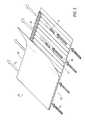
- FIG. 1is an exploded, perspective view of a filter structure in accordance with an exemplary embodiment of the invention
- FIG. 2is an assembled, perspective view of the filter structure of FIG. 1 in accordance with an exemplary embodiment of the invention
- FIG. 3is a perspective, cross-sectional view of the filter structure of FIG. 2 according to line 3 - 3 in accordance with an exemplary embodiment of the invention
- FIGS. 4A-4Geach illustrate an enlarged, cross-sectional view of the filter structure of FIG. 3 according to line 4 in accordance with an exemplary embodiment of the invention.
- FIG. 5is a perspective view of a layer of filter media of the filter structure in accordance with an exemplary embodiment of the invention.
- the filter structure 10includes a pre-filter 12 , a filter body 14 , a casing 16 and a seal 18 .
- the filter structure 10may include a core 19 .
- an axis, A-Agenerally extends through the filter structure 10 .
- the filter body 14includes an outer side surface 20 , that may be bound by a first axial end surface 22 and a second axial end surface 24 .
- the filter body 14is designed to receive a dirty fluid, such as, for example, air, according to the direction of the arrow, F D .
- a dirty fluidsuch as, for example, air
- the dirty fluid, F Denters the filter body 14 at the pre-filter 12 and the first axial end surface 22 of the filter body 14 ; as such, the first axial end surface 22 may be referred to as the “dirty side flow face” of the filter body 14 .
- any impurities that are contained in the dirty fluid, F Dare removed therefrom such that the dirty fluid, F D , is thereafter referred to as clean fluid, that is directed away from the filter body 14 according to the direction of the arrow, F C .
- the clean fluid, F Cexits the filter body 14 from the second axial end surface 24 .
- the second axial end surface 24may be referred to as the “clean side flow face.”
- the casing 16may include a sidewall 26 .
- the sidewall 26includes an inner surface 28 and an outer surface 30 .
- the casing 16may include one or more upper lips 32 a and one or more lower lips 32 b that extend radially outwardly and away from the outer surface 30 of the sidewall 26 .
- each lip 32 a , 32 bincludes a dirty side surface 34 and a clean side surface 36 .
- a collar 38extends axially away from the dirty side surface 34 of the one or more upper lips 32 a .
- the collar 38includes an inner surface 40 and an outer surface 42 .
- the casing 16further includes a dirty side axial end surface 44 and a clean side axial end surface 46 .
- the dirty side axial end surface 44 of the casing 16includes the collar 38 .
- the clean side axial end surface 46 of the casing 16includes one or more of the lower lips 32 b and sidewall 26 .
- the casing 16is defined by a length, L, that extends from the dirty side axial end surface 44 to the clean side axial end surface 46 .
- the length, Lincludes a first sub-length, L 1 , and a second sub-length, L 2 .
- the first sub-length, L 1extends from about the dirty side axial end surface 44 to the clean side surface 36 of the one or more upper lips 32 s .
- the second sub-length, L 2extends from about the clean side surface 36 of the one or more upper lips 32 a to the clean side axial end surface 46 of the casing 16 .
- the relationship of the first sub-length, L 1 , and the second sub-length, L 2 , to the remaining elements of the filter structure 10is described in greater detail in the foregoing disclosure.
- the collar 38is aligned with the sidewall 26 .
- the sidewall 26 and collar 38define a volume, V, including a first sub-volume, V 1 , and a second sub-volume, V 2 .
- the first sub-volume, V 1functions by receiving the pre-filter 12 and filter body 14 .
- function of the second sub-volume, V 2is described in greater detail herein.
- the casing 16is an integral component, comprising a substantially rigid material.
- the material used with the casing 16may include, for example, nylon, polypropylene or the like.
- the filter body 14is disposed within the first sub-volume, V 1 , of the casing 16 such that the outer side surface 20 of the filter body 14 is disposed substantially adjacent the inner side surface 28 of the casing 16 .
- the seal 18is formed/disposed over a portion 48 of the clean side flow face 24 of the filter body 14 and the clean side axial end surface 46 of the casing 16 .
- the seal 18may comprise a substantially flexible, non-rigid material.
- the material defining the seal 18may include, for example, polyurethane.
- the portion 48 of the clean side flow face 24 of the filter body 14includes a stepped ledge defined by an axial ledge surface 50 and a radial ledge surface 52 .
- the seal 18substantially covers all of the axial ledge surface 50 and at least partially covers the radial ledge surface 52 .
- the clean side flow face 24 of the filter body 14extends axially past the clean side axial end surface 46 of the casing 16 .
- an axial portion 54 a of the seal 18extends axially past the clean side flow face 24 of the filter body 14 .
- a radial portion 54 b of the seal 18extends radially past the outer surface 30 of the casing 16 . It will be appreciated, however, that the filter body 14 and seal 18 may include any desirable dimension relative the casing 16 and is not limited to the embodiment shown and described in the present disclosure.
- the pre-filter 12may be disposed within the first sub-volume, V 1 , of the casing 16 , proximate the collar 38 , and substantially adjacent one or more of the inner surface 28 of the sidewall 26 and the dirty side flow face 22 of the filter body 14 .
- the pre-filter 12is positioned into the first sub-volume, V 1 , at a distance away from the dirty side axial end surface 44 approximately equal to the first sub-length, L 1 , of the casing 16 .
- the pre-filter 12defines a substantially annular shape having an outer circumferential surface 56 , a dirty side surface 58 and a clean side surface 60 .
- the pre-filter 12defines a substantially porous foam material, such as, for example, polyurethane ester. It will be appreciated, however, that the pre-filter 12 may include materials other than foam, such as, for example, a non-woven fabric, a wire mesh, a plastic mesh, or the like.
- a filter structureis shown generally at 10 a in accordance with an embodiment of the invention.
- the clean side surface 60 of the pre-filter 12is disposed substantially adjacent the dirty side flow face 22 of the filter body 14
- the outer side surface 56is disposed substantially adjacent the inner surface 28 of the casing 16 .
- an adhesivemay be applied to one or more surfaces 56 , 60 or 22 , 28 in order to attach the pre-filter 12 to one or more of the filter body 14 and casing 16 .
- an adhesivemay be applied to the dirty side flow face 22 of the filter body 14 such that upon disposing the pre-filter 12 adjacent the filter body 14 , the clean side surface 60 of pre-filter 12 is axially adhered to the filter body 14 .
- an adhesivemay be applied to the clean side surface 60 of the pre-filter 12 such that upon disposing the pre-filter 12 adjacent the filter body 14 , the clean side surface 60 of pre-filter 12 is axially adhered to the filter body 14 .
- an adhesivemay be applied adjacent to the inner surface 28 of the casing 16 such that the outer circumferential surface 56 of the pre-filter 12 is radially adhered to the casing 16 .
- an adhesivemay be applied to the outer circumferential surface 56 of the pre-filter 12 such that the outer circumferential surface 56 of the pre-filter 12 is radially adhered to the casing 16 .
- a filter structureis shown generally at 10 b that may not, in an embodiment, include adhesive.
- the pre-filter 12 of the filter structure 10 bmay define a first radial cross-sectional geometry, which is shown generally at G 1 .
- a portion of the casing 16 that is proximate, for example, the collar 38may define a second radial cross-sectional geometry, which is shown generally at G 2 .
- the first radial cross-sectional geometry, G 1may be substantially similar to the second radial cross-sectional geometry, G 2 .
- the pre-filter 12may be retained adjacent the casing 16 in a friction-fit connection, FF (see, e.g., FIG. 4B ), such that the outer circumferential surface 56 of the pre-filter 12 is forced into and presses against the inner surface 28 of the casing 16 .
- FFfriction-fit connection
- the pre-filter 12may not be disposed substantially adjacent the dirty side flow face 22 of the filter body 14 , and, appear to buckle/bubble, B, axially away from the dirty side flow face 22 of the filter body 14 at a location substantially near or proximate the inner surface 28 of the casing 16 .
- any buckling/bubbling, Bmay be obviated by sizing the first radial cross-sectional geometry, G 1 , to be greater than, but approximately equal to the second radial cross-sectional geometry, G 2 , of the casing 16 .
- the friction-fit connection, FFmay be enhanced, modified or supported by the application of the adhesive to one or more of the surfaces 56 , 60 or 22 , 28 as described above in a previous embodiment.
- the first radial cross-sectional geometry, G 1 , of the pre-filter 12is proportionally the same as, but, slightly greater than the second radial cross-sectional geometry, G 2 , of a portion of the casing 16 as similarly described above.
- the inner side surface 28 of the casing 16may be defined by a radial recess 62 defined by an axial, lower ledge surface 64 , a radial side surface 66 and an axial, upper ledge surface 68 .
- a circumferential portion 70 of the pre-filter 12is nested within the radial recess 62 .
- the circumferential portion 70includes a portion of the clean side surface 60 of the pre-filter 12 disposed adjacent the axial, lower ledge surface 64 , the outer circumferential surface 56 disposed adjacent the radial side surface 66 , and a portion of the dirty side surface 58 disposed adjacent the upper ledge surface 68 .
- filter structure 10 cincludes the pre-filter 12 having the first radial cross-sectional geometry, G 1 , that is proportionally the same as, but, slightly greater than the second radial cross-sectional geometry, G 2 , of the casing 16 proximate the collar 38 , the buckling/bubbling, B, that may be potentially exhibited by the pre-filter 12 , as shown in FIG. 4B , is obviated, and, the clean side surface 60 of the pre-filter 12 may be disposed substantially axially adjacent the dirty side flow face 22 of the filter body 14 without interruption.
- the nested connection of the pre-filter 12 at the radial recess 62 of the casing 16may be enhanced, modified or supported by the application of the adhesive to one or more of the surfaces 56 , 60 or 22 , 28 as described above in a previous embodiment, and/or, an application of the adhesive to one or more of the surfaces 64 - 68 defined by the radial recess 62 .
- the inner side surface 28 of the casing 12includes a plurality of radially inwardly projecting barbs 72 .
- the plurality of radially-inwardly projecting barbs 72extend radially inwardly along a portion of the inner side surface 28 of the casing 12 for a length approximately equal to a thickness, T 1 (see also, e.g. FIG. 3 ), of the pre-filter 12 .
- the clean side surface 60 of the pre-filter 12is disposed substantially adjacent the dirty side flow face 22 of the filter body 14
- the outer side surface 56is disposed substantially adjacent the plurality of radially-inwardly projecting barbs 72 .
- the pre-filter 12may be structurally retained by the casing 16 .
- the structural connection of the pre-filter 12 and the casing 16 described abovemay be enhanced, modified or supported by the application of the adhesive to one or more of the plurality of radially inwardly projecting barbs 72 and surfaces 56 , 60 or 22 , 28 as described above in a previous embodiment.
- the filter structure 10 eis substantially similar to the filter structure 10 c with the exception that the clean side surface 60 of the pre-filter 12 is spaced away from the dirty side flow face 22 of the filter body 14 at a distance, D.
- the distance, Dmay be achieved by reducing an overall thickness, T 2 (see, e.g., FIG. 3 ), of the filter body 14 such that upon nesting the circumferential portion 70 into the radial recess 62 of the casing 16 , the spacing as defined by the distance, D, is created.
- FIG. 4Fanother embodiment of a filter structure is shown generally at 10 f in accordance with an embodiment of the invention.
- the filter structure 10 fis substantially similar to the filter structure 10 a with the exception that the clean side surface 60 of the pre-filter 12 is spaced away from the dirty side flow face 22 of the filter body 14 at the distance, D.
- the distance, Dmay be achieved by disposing a porous spacing member 75 between the clean side surface 60 of the pre-filter 12 and the dirty side flow face 22 of the filter body 14 .
- the overall thickness, T 2 , of the filter body 14may be reduced in order to accommodate the disposing of the porous spacing portion 75 within the first sub-volume, V 1 .
- the porous spacing member 75may include a wire mesh or the like. It will be appreciated, however, that the porous spacing member 75 is not limited to a wire mesh and may include, for example, a plastic mesh, non-woven fabric or the like.
- the porous spacing member 75may include, for example, a substantially sinusoidal cross-section.
- an upper surface/peak portion 77 of the porous spacing member 75may be disposed substantially adjacent the clean side surface of the pre-filter 12
- a lower surface/valley portion 79may be disposed adjacent the dirty side flow face 22 of the filter body 14 .
- the porous spacing member 75is not limited to include a substantially sinusoidal cross-section and that the porous spacing member 75 may include any desirable cross-section, such as, for example, a substantially uniform cross-section defining a substantially flat sheet having parallel upper and lower surfaces 77 , 79 .
- the porous spacing member 75may provide an additional function as a filter element. Accordingly, in an embodiment, the pre-filter 12 may be referred to as a first stage pre-filter, and, the porous spacing member 75 may be referred to as a second stage pre-filter. Accordingly, in an embodiment, it will be appreciated that the porous spacing member 75 may include any desirable material, such as, for example, a foam material, a non-woven fabric, a wire mesh, or a plastic mesh that functions as a pre-filter in a substantially similar manner as that of the pre-filter 12 .
- pre-filter 12includes a flange 81 that axially depends toward the filter body 14 , when the pre-filter 12 is disposed upon the filter body 14 or installed within the casing 16 .
- flange 81may continuously extend around the pre-filter 12 or the flange 81 may be selectively positioned around the pre-filter.
- the flange 81is provided to positionally retain the pre-filter 12 within the casing 16 as it becomes snugly disposed between the filter body 14 and the inner surface 28 of the sidewall 26 of the casing 16 .
- the pre-filteris compressably retained thereby.
- the pre-filter 12is arranged proximate the filter 14 such that the flange 81 of the pre-filter is proximate a side of filter body 14 to form a sub-assembly; thereafter, this subassembly is inserted into casing 16 so that the subassembly frictionally engages the inner surface 28 of the sidewall 26 of the casing 16 whereby the flange 81 is intermediately disposed between inner surface 28 of the sidewall 26 of the casing and a side of the filter body 14 . While the depiction of FIG.
- 4Gillustrates that a space may be provided axially beneath a terminal end of flange 81 and between the inner surface 28 of the sidewall 26 of the casing 16 and the side of the filter element, it is to be appreciated (based on this disclosure) that the space may be de minimis or, depending on the width and compressibility of the pre-filter 12 , eliminated.
- the spacemay be de minimis or, depending on the width and compressibility of the pre-filter 12 , eliminated.
- the pre-filer 12 and the filter body 14define a filter sub-assembly 74 that is disposed within the first sub-volume, V 1 , of the casing 12 .
- the filter sub-assembly 74may be defined to have a thickness, T.
- the thickness, Tmay be defined by the sum of the thickness, T 1 , of the pre-filter 12 and the thickness, T 2 , of the filter body 14 .
- the thickness, T, of the filter sub-assembly 74is approximately equal to, but greater than the second sub-length, L 2 , of the casing 16 .
- the impurities that are contained in the dirty fluid, F Dmay include, for example, fine particulates, P 1 , course particulates, P 2 , and large particulates, P 3 .
- the fine particulates, P 1may include, for example, microscopic dust particles, dirt particles, or the like.
- the course particulates, P 2may include, for example, relatively small stones, rocks or pebbles.
- the large particulates, P 3may include, for examples, leafs, plastic bags, or the like.
- the pre-filter 12filters one or more of the course particulates, P 2 , and the large particulates, P 3 , from the fine particulates, P 1 , by receiving and retaining one or more of the course particulates, P 2 , and the large particulates, P 3 , at the dirty side surface 58 of the pre-filter 12 .
- the pre-filter 12is disposed and recessed into the first sub-volume, V 1 , at a distance away from the dirty side axial end surface 44 approximately equal to the first sub-length, L 1 , such that the second sub-volume, V 2 , is not occupied by one or more of the pre-filter 12 and filter body 14 .
- the second sub-volume, V 2is defined by the inner surface 40 of the collar 38 and the dirty side surface 58 of the pre-filter 12 .
- the structure defining the second sub-volume, V 2i.e. the pre-filter 12 and the collar 38 ), may contain the course particulates, P 2 , and the large particulates, P 3 , that are removed from the dirty fluid, F D , as the fine particulates, P 1 , are permitted to pass through the pre-filter 12 .
- the porosity of the pre-filter 12is porous enough such that the fine particulates, P 1 , are permitted to be filtered by and/or passed through the thickness, T 1 , of the pre-filter 12 such that the fine particulates, P 1 , are permitted to enter into the filter body 14 at the dirty side flow face 22 . It will be appreciated that when one or more of the course particulates, P 2 , and the large particulates, P 3 , are received and retained within the second sub-volume, V 2 , the life and/or filtering capacity/capability of the media body 14 is increased.
- the filter media body 14is generally defined by a sheet 76 of fluted or corrugated filter media. As seen in FIG. 1 , the sheet 76 is rolled upon itself to form the filter media body 14 . In an embodiment, the sheet 76 is defined by a plurality of neighboring channels 78 each having an entrance opening 80 and an exit opening 82 . In an embodiment, the plurality of entrance openings 80 generally define the dirty side flow face 22 . In an embodiment, the plurality of exit openings 82 generally define the clean side flow face 24 .
- the filter body 14removes the fine particulates, P 1 , from the dirty fluid, F D , by permitting the dirty fluid, F D , to axially enter the entrance opening 80 , and then, after axially entering the entrance opening 80 , the dirty fluid, F D , is radially directed, R, from the channel 78 , and through the sheet 76 . Once moved through the sheet 76 , the fine particulates, P 1 , are removed from the dirty fluid, F D , such that the dirty fluid, F D , is thereafter referred to as clean fluid, F C , that axially exits the filter body 14 at the exit opening 82 .
- the filter body 14does not have to be serviced or replaced with a greater frequency by removing one or more of the course particulates, P 2 , and the large particulates, P 3 , from the dirty side flow face 22 of the filter body 14 .
Landscapes
- Chemical & Material Sciences (AREA)
- Chemical Kinetics & Catalysis (AREA)
- Filtering Of Dispersed Particles In Gases (AREA)
- Filtering Materials (AREA)
Abstract
Description
Claims (12)
Priority Applications (1)
| Application Number | Priority Date | Filing Date | Title |
|---|---|---|---|
| US13/477,804US8641901B2 (en) | 2009-04-01 | 2012-05-22 | Filter structure |
Applications Claiming Priority (2)
| Application Number | Priority Date | Filing Date | Title |
|---|---|---|---|
| US12/416,717US8192623B2 (en) | 2009-04-01 | 2009-04-01 | Filter structure |
| US13/477,804US8641901B2 (en) | 2009-04-01 | 2012-05-22 | Filter structure |
Related Parent Applications (1)
| Application Number | Title | Priority Date | Filing Date |
|---|---|---|---|
| US12/416,717ContinuationUS8192623B2 (en) | 2009-04-01 | 2009-04-01 | Filter structure |
Publications (2)
| Publication Number | Publication Date |
|---|---|
| US20120228210A1 US20120228210A1 (en) | 2012-09-13 |
| US8641901B2true US8641901B2 (en) | 2014-02-04 |
Family
ID=42825312
Family Applications (2)
| Application Number | Title | Priority Date | Filing Date |
|---|---|---|---|
| US12/416,717Active2030-05-17US8192623B2 (en) | 2009-04-01 | 2009-04-01 | Filter structure |
| US13/477,804ActiveUS8641901B2 (en) | 2009-04-01 | 2012-05-22 | Filter structure |
Family Applications Before (1)
| Application Number | Title | Priority Date | Filing Date |
|---|---|---|---|
| US12/416,717Active2030-05-17US8192623B2 (en) | 2009-04-01 | 2009-04-01 | Filter structure |
Country Status (1)
| Country | Link |
|---|---|
| US (2) | US8192623B2 (en) |
Cited By (1)
| Publication number | Priority date | Publication date | Assignee | Title |
|---|---|---|---|---|
| USD1085386S1 (en)* | 2018-05-08 | 2025-07-22 | Cummins Filtration Ip, Inc. | Filter element |
Families Citing this family (28)
| Publication number | Priority date | Publication date | Assignee | Title |
|---|---|---|---|---|
| CN1079275C (en)* | 1996-04-26 | 2002-02-20 | 唐纳森公司 | Fluted filter media |
| US8192623B2 (en)* | 2009-04-01 | 2012-06-05 | Wix Filtration Corp Llc | Filter structure |
| US8920066B1 (en) | 2011-01-12 | 2014-12-30 | Tuf-Tite, Inc. | Tactile sidewalk surface |
| USD706831S1 (en)* | 2011-02-11 | 2014-06-10 | Briggs & Stratton Corporation | Air filter |
| USD690407S1 (en)* | 2012-12-10 | 2013-09-24 | K&N Engineering, Inc. | Air filter |
| USD697191S1 (en)* | 2012-12-11 | 2014-01-07 | K&N Engineering, Inc. | Air filter |
| USD804004S1 (en)* | 2013-09-04 | 2017-11-28 | Mann+Hummel Gmbh | Air filter element |
| USD775317S1 (en)* | 2013-09-04 | 2016-12-27 | Mann+Hummel Gmbh | Air filter element |
| USD766415S1 (en)* | 2015-04-01 | 2016-09-13 | Coway Co., Ltd. | Air purifier |
| USD798907S1 (en) | 2015-11-20 | 2017-10-03 | Baldwin Filters, Inc. | Filter element |
| USD786935S1 (en)* | 2015-11-20 | 2017-05-16 | Baldwin Filters, Inc. | Filter element |
| USD799657S1 (en)* | 2016-05-12 | 2017-10-10 | Briggs & Stratton Corporation | Filter |
| USD852345S1 (en)* | 2017-04-07 | 2019-06-25 | Champion Laboratories, Inc. | Filter |
| USD885546S1 (en)* | 2017-08-09 | 2020-05-26 | Donaldson Company, Inc. | Filter cartridge |
| USD885545S1 (en)* | 2017-08-09 | 2020-05-26 | Donaldson Company, Inc. | Filter cartridge |
| KR102585171B1 (en) | 2017-08-09 | 2023-10-05 | 도날드슨 컴파니, 인코포레이티드 | Filter cartridges, air cleaner assemblies, housings, features, components, and methods |
| US10480784B2 (en)* | 2017-08-10 | 2019-11-19 | Lennox Industries Inc. | Inlet screen assembly for ultra low NOx gas-air mixing system |
| DE112018006269T5 (en) | 2017-12-08 | 2020-08-20 | Cummins Filtration Ip, Inc. | Oval seal with stabilizing contour |
| US10920378B2 (en) | 2018-01-19 | 2021-02-16 | Tuf-Tite, Inc. | Stamped steel detectable warning tile and method of manufacture |
| FR3078490B1 (en)* | 2018-03-05 | 2022-10-14 | Cummins Filtration Sarl | FILTERING ELEMENT AND HOUSING HAVING NON-CIRCULAR CROSS-SECTIONS |
| US10918978B2 (en) | 2018-05-08 | 2021-02-16 | Cummins Filtration Ip, Inc. | Oval filter with exterior elliptical radial seal and internal support structure |
| USD1002792S1 (en) | 2019-02-05 | 2023-10-24 | Donaldson Company, Inc. | Filter cartridge |
| USD969289S1 (en) | 2020-03-05 | 2022-11-08 | Cummins Filtration Inc. | Filter element |
| JP1679793S (en)* | 2020-03-25 | 2021-04-19 | ||
| JP1679792S (en)* | 2020-03-25 | 2021-04-19 | ||
| USD946733S1 (en)* | 2020-07-05 | 2022-03-22 | Champion Laboratories, Inc. | Filter frame |
| USD1067404S1 (en) | 2022-01-07 | 2025-03-18 | Donaldson Company, Inc. | Filter cartridge |
| USD1064220S1 (en) | 2022-01-07 | 2025-02-25 | Donaldson Company, Inc. | Filter cartridge |
Citations (41)
| Publication number | Priority date | Publication date | Assignee | Title |
|---|---|---|---|---|
| US2582388A (en)* | 1948-12-29 | 1952-01-15 | Edward H Mansfield | Filter |
| US3386580A (en)* | 1965-07-22 | 1968-06-04 | Allen Bradley Co | Stackable sieve construction for use in reciprocating air column sifters and the like |
| US4689145A (en)* | 1986-08-01 | 1987-08-25 | Mathews Lester R | Dry well filtration system |
| US5690825A (en)* | 1993-12-21 | 1997-11-25 | Genera Technologies Limited | Filtration method and apparatus |
| US5820646A (en) | 1996-04-26 | 1998-10-13 | Donaldson Company, Inc. | Inline filter apparatus |
| USD417268S (en) | 1996-04-26 | 1999-11-30 | Donaldson Company, Inc. | Oval filter |
| US6179890B1 (en) | 1999-02-26 | 2001-01-30 | Donaldson Company, Inc. | Air cleaner having sealing arrangement between media arrangement and housing |
| USD437402S1 (en) | 1999-11-05 | 2001-02-06 | Donaldson Company, Inc. | Filter element with centerpiece |
| US6190432B1 (en) | 1999-02-26 | 2001-02-20 | Donaldson Company, Inc. | Filter arrangement; sealing system; and methods |
| US6235195B1 (en) | 1999-02-26 | 2001-05-22 | Donaldson Company, Inc. | Filter element incorporating a handle member |
| US6348085B1 (en) | 1999-11-10 | 2002-02-19 | Donaldson Company, Inc. | Filter arrangement and methods |
| US6416605B1 (en) | 1999-11-24 | 2002-07-09 | Donaldson Company, Inc. | Method for manufacturing fluted media |
| USD466602S1 (en) | 1999-02-26 | 2002-12-03 | Donaldson Company, Inc. | Filter element having sealing system |
| US6517598B2 (en) | 2001-06-06 | 2003-02-11 | Donaldson Company, Inc. | Filter element having flange and methods |
| US6554139B1 (en) | 2000-06-01 | 2003-04-29 | Parker-Hannifin Corporation | Extension and locking assembly for dripless element, and container therefore |
| US6610126B2 (en) | 2001-06-06 | 2003-08-26 | Donaldson Company, Inc. | Filter element having sealing members and methods |
| US6610117B2 (en) | 1999-02-26 | 2003-08-26 | Donaldson Company, Inc. | Filter arrangement; sealing system; and methods |
| US20030205140A1 (en)* | 2000-06-05 | 2003-11-06 | Flaugher David V | Ploypropylene or polyester plastic dessicant cartridge with fiberglass filter and bead cage ends |
| USD483459S1 (en) | 2002-01-23 | 2003-12-09 | Donaldson Company, Inc. | Air filter element for engine |
| US6746518B2 (en) | 1999-11-05 | 2004-06-08 | Donaldson Company, Inc. | Filter element, air cleaner, and methods |
| US6797168B1 (en) | 1999-12-03 | 2004-09-28 | Parker-Hannifin Corporation | Keyed latch valve for fuel filter |
| USD497202S1 (en) | 2002-11-22 | 2004-10-12 | Donaldson Company, Inc. | Filter for engine |
| US6966940B2 (en) | 2002-04-04 | 2005-11-22 | Donaldson Company, Inc. | Air filter cartridge |
| US7140560B2 (en) | 2003-09-26 | 2006-11-28 | Parker-Hannifin Corporation | Nozzle assembly with fuel tube deflector |
| US7147110B2 (en) | 2003-08-01 | 2006-12-12 | Parker-Hannifin Corporation | Filter assembly with vented filter element |
| US20070039296A1 (en) | 2003-03-18 | 2007-02-22 | Donaldson Company Inc. | Process and materials for coiling z-filter media, and/or closing flutes of filter media; and, products |
| US20070175194A1 (en) | 2003-11-12 | 2007-08-02 | Donaldson Company, Inc. | Filter arrangements; side-entry housings; and methods |
| US20070261374A1 (en) | 2006-05-10 | 2007-11-15 | Benny Kevin Nelson | Air filter arrangement; assembly; and, methods |
| US20070289265A1 (en) | 2004-04-30 | 2007-12-20 | Donaldson Company, Inc. | Filter Arrangements; Housing; Assemblies; and, Methods |
| US20080016832A1 (en) | 2004-03-24 | 2008-01-24 | Donaldson Company, Inc. | Filter Elements; Air Cleaner; Assemby; And Methods |
| US20080066434A1 (en) | 2006-06-22 | 2008-03-20 | Kuempel Bradley A | Air cleaner arrangements; components thereof; and, methods |
| US20080086990A1 (en) | 2006-01-20 | 2008-04-17 | Kuempel Bradley A | Air cleaner configured for receipt of various sized filter cartridges; components thereof; and, methods |
| US20080110142A1 (en) | 2004-07-20 | 2008-05-15 | Donaldson Company, Inc. | Z-Filter Media Pack Arrangement; Filter Cartridge; Air Cleaner Arrangement; and, Methods |
| US20080115758A1 (en) | 2003-02-11 | 2008-05-22 | Donaldson Company, Inc. | Air cleaner arrangements; serviceable filter elements; and, methods |
| US20080115470A1 (en) | 2006-06-22 | 2008-05-22 | Kuempel Bradley A | Air cleaner arrangements; components thereof; and, methods |
| US7396376B2 (en) | 2003-12-22 | 2008-07-08 | Donaldson Company, Inc. | Seal arrangement for filter element; filter element assembly; and, methods |
| US7396375B2 (en) | 2002-05-09 | 2008-07-08 | Donaldson Company, Inc. | Air filter having fluted filter media |
| US20080216654A1 (en) | 1996-04-26 | 2008-09-11 | Donaldson Company, Inc. | Fluted filter media |
| US20080250766A1 (en) | 2004-06-08 | 2008-10-16 | Donaldson Company, Inc. | Z-Filter Media Pack Arrangement; and, Methods |
| US20080276582A1 (en) | 2004-06-14 | 2008-11-13 | Bruce Allen Boehrs | Air Filter Arrangement; Assembly; and, Methods |
| US8192623B2 (en)* | 2009-04-01 | 2012-06-05 | Wix Filtration Corp Llc | Filter structure |
- 2009
- 2009-04-01USUS12/416,717patent/US8192623B2/enactiveActive
- 2012
- 2012-05-22USUS13/477,804patent/US8641901B2/enactiveActive
Patent Citations (58)
| Publication number | Priority date | Publication date | Assignee | Title |
|---|---|---|---|---|
| US2582388A (en)* | 1948-12-29 | 1952-01-15 | Edward H Mansfield | Filter |
| US3386580A (en)* | 1965-07-22 | 1968-06-04 | Allen Bradley Co | Stackable sieve construction for use in reciprocating air column sifters and the like |
| US4689145A (en)* | 1986-08-01 | 1987-08-25 | Mathews Lester R | Dry well filtration system |
| US5690825A (en)* | 1993-12-21 | 1997-11-25 | Genera Technologies Limited | Filtration method and apparatus |
| US20080216654A1 (en) | 1996-04-26 | 2008-09-11 | Donaldson Company, Inc. | Fluted filter media |
| US5820646A (en) | 1996-04-26 | 1998-10-13 | Donaldson Company, Inc. | Inline filter apparatus |
| USD417268S (en) | 1996-04-26 | 1999-11-30 | Donaldson Company, Inc. | Oval filter |
| US6350291B1 (en) | 1999-02-26 | 2002-02-26 | Donaldson Company, Inc. | Filter arrangement; sealing system; and methods |
| US6610117B2 (en) | 1999-02-26 | 2003-08-26 | Donaldson Company, Inc. | Filter arrangement; sealing system; and methods |
| US6235195B1 (en) | 1999-02-26 | 2001-05-22 | Donaldson Company, Inc. | Filter element incorporating a handle member |
| US20010003893A1 (en) | 1999-02-26 | 2001-06-21 | Donaldson Company, Inc. | Air cleaner, filter element, and methods |
| US6179890B1 (en) | 1999-02-26 | 2001-01-30 | Donaldson Company, Inc. | Air cleaner having sealing arrangement between media arrangement and housing |
| US6783565B2 (en) | 1999-02-26 | 2004-08-31 | Donaldson Company, Inc. | Filter arrangement; sealing system; and methods |
| USD466602S1 (en) | 1999-02-26 | 2002-12-03 | Donaldson Company, Inc. | Filter element having sealing system |
| US6190432B1 (en) | 1999-02-26 | 2001-02-20 | Donaldson Company, Inc. | Filter arrangement; sealing system; and methods |
| US20080209874A1 (en) | 1999-02-26 | 2008-09-04 | Donaldson Company, Inc. | Filter arrangement; sealing system; and methods |
| US7303604B2 (en) | 1999-02-26 | 2007-12-04 | Donaldson Company, Inc. | Filter arrangement; sealing system; and methods |
| US6746518B2 (en) | 1999-11-05 | 2004-06-08 | Donaldson Company, Inc. | Filter element, air cleaner, and methods |
| USD437402S1 (en) | 1999-11-05 | 2001-02-06 | Donaldson Company, Inc. | Filter element with centerpiece |
| US6533845B2 (en) | 1999-11-10 | 2003-03-18 | Donaldson Company, Inc. | Filter arrangement and methods |
| US7252704B2 (en) | 1999-11-10 | 2007-08-07 | Donaldson Company, Inc. | Filter arrangement and methods |
| US6994744B2 (en) | 1999-11-10 | 2006-02-07 | Donaldson Company, Inc. | Filter arrangement and methods |
| US6960245B2 (en) | 1999-11-10 | 2005-11-01 | Donaldson Company, Inc. | Filter arrangement and methods |
| US6348085B1 (en) | 1999-11-10 | 2002-02-19 | Donaldson Company, Inc. | Filter arrangement and methods |
| US6416605B1 (en) | 1999-11-24 | 2002-07-09 | Donaldson Company, Inc. | Method for manufacturing fluted media |
| US6797168B1 (en) | 1999-12-03 | 2004-09-28 | Parker-Hannifin Corporation | Keyed latch valve for fuel filter |
| US6986426B2 (en) | 2000-06-01 | 2006-01-17 | Parker Intangibles Inc. | Extension and locking assembly for dripless element, and container therefore |
| US7086537B2 (en) | 2000-06-01 | 2006-08-08 | Parker-Hannifin Corporation | Extension and locking assembly for dripless element, and container therefore |
| US6554139B1 (en) | 2000-06-01 | 2003-04-29 | Parker-Hannifin Corporation | Extension and locking assembly for dripless element, and container therefore |
| US20030205140A1 (en)* | 2000-06-05 | 2003-11-06 | Flaugher David V | Ploypropylene or polyester plastic dessicant cartridge with fiberglass filter and bead cage ends |
| US6610126B2 (en) | 2001-06-06 | 2003-08-26 | Donaldson Company, Inc. | Filter element having sealing members and methods |
| US20080264008A1 (en) | 2001-06-06 | 2008-10-30 | Donaldson Company, Inc. | Filter element having sealing members and methods |
| US6878190B1 (en) | 2001-06-06 | 2005-04-12 | Donaldson Company, Inc. | Filter element having sealing members and methods |
| US6517598B2 (en) | 2001-06-06 | 2003-02-11 | Donaldson Company, Inc. | Filter element having flange and methods |
| US6997968B2 (en) | 2001-06-06 | 2006-02-14 | Donaldson Company, Inc. | Filter element having sealing members and methods |
| US7393375B2 (en) | 2001-06-06 | 2008-07-01 | Donaldson Company, Inc. | Filter element having sealing members and methods |
| USD483459S1 (en) | 2002-01-23 | 2003-12-09 | Donaldson Company, Inc. | Air filter element for engine |
| US6966940B2 (en) | 2002-04-04 | 2005-11-22 | Donaldson Company, Inc. | Air filter cartridge |
| US7396375B2 (en) | 2002-05-09 | 2008-07-08 | Donaldson Company, Inc. | Air filter having fluted filter media |
| US20080271423A1 (en) | 2002-05-09 | 2008-11-06 | Donaldson Company, Inc. | Air filter having fluted filter media |
| USD497202S1 (en) | 2002-11-22 | 2004-10-12 | Donaldson Company, Inc. | Filter for engine |
| US20080115758A1 (en) | 2003-02-11 | 2008-05-22 | Donaldson Company, Inc. | Air cleaner arrangements; serviceable filter elements; and, methods |
| US20070039296A1 (en) | 2003-03-18 | 2007-02-22 | Donaldson Company Inc. | Process and materials for coiling z-filter media, and/or closing flutes of filter media; and, products |
| US7147110B2 (en) | 2003-08-01 | 2006-12-12 | Parker-Hannifin Corporation | Filter assembly with vented filter element |
| US7140560B2 (en) | 2003-09-26 | 2006-11-28 | Parker-Hannifin Corporation | Nozzle assembly with fuel tube deflector |
| US20070175194A1 (en) | 2003-11-12 | 2007-08-02 | Donaldson Company, Inc. | Filter arrangements; side-entry housings; and methods |
| US7396376B2 (en) | 2003-12-22 | 2008-07-08 | Donaldson Company, Inc. | Seal arrangement for filter element; filter element assembly; and, methods |
| US20080264020A1 (en) | 2003-12-22 | 2008-10-30 | Donaldson Company, Inc. | Seal arrangement for filter element; filter element assembly; and, methods |
| US20080016832A1 (en) | 2004-03-24 | 2008-01-24 | Donaldson Company, Inc. | Filter Elements; Air Cleaner; Assemby; And Methods |
| US20070289265A1 (en) | 2004-04-30 | 2007-12-20 | Donaldson Company, Inc. | Filter Arrangements; Housing; Assemblies; and, Methods |
| US20080250766A1 (en) | 2004-06-08 | 2008-10-16 | Donaldson Company, Inc. | Z-Filter Media Pack Arrangement; and, Methods |
| US20080276582A1 (en) | 2004-06-14 | 2008-11-13 | Bruce Allen Boehrs | Air Filter Arrangement; Assembly; and, Methods |
| US20080110142A1 (en) | 2004-07-20 | 2008-05-15 | Donaldson Company, Inc. | Z-Filter Media Pack Arrangement; Filter Cartridge; Air Cleaner Arrangement; and, Methods |
| US20080086990A1 (en) | 2006-01-20 | 2008-04-17 | Kuempel Bradley A | Air cleaner configured for receipt of various sized filter cartridges; components thereof; and, methods |
| US20070261374A1 (en) | 2006-05-10 | 2007-11-15 | Benny Kevin Nelson | Air filter arrangement; assembly; and, methods |
| US20080115470A1 (en) | 2006-06-22 | 2008-05-22 | Kuempel Bradley A | Air cleaner arrangements; components thereof; and, methods |
| US20080066434A1 (en) | 2006-06-22 | 2008-03-20 | Kuempel Bradley A | Air cleaner arrangements; components thereof; and, methods |
| US8192623B2 (en)* | 2009-04-01 | 2012-06-05 | Wix Filtration Corp Llc | Filter structure |
Non-Patent Citations (2)
| Title |
|---|
| Non-Final Office Action dated Aug. 25, 2011, relating to U.S. Appl. No. 12/416,717. |
| Restriction Requirement dated Jun. 14, 2011, relating to U.S. Appl. No. 12/416,717. |
Cited By (1)
| Publication number | Priority date | Publication date | Assignee | Title |
|---|---|---|---|---|
| USD1085386S1 (en)* | 2018-05-08 | 2025-07-22 | Cummins Filtration Ip, Inc. | Filter element |
Also Published As
| Publication number | Publication date |
|---|---|
| US20120228210A1 (en) | 2012-09-13 |
| US20100252495A1 (en) | 2010-10-07 |
| US8192623B2 (en) | 2012-06-05 |
Similar Documents
| Publication | Publication Date | Title |
|---|---|---|
| US8641901B2 (en) | Filter structure | |
| US7740678B2 (en) | High capacity filter | |
| US9889398B2 (en) | Filter cartridges; features and methods of assembly; air cleaner assemblies; and, filter cartridge combinations | |
| US20190358572A1 (en) | Filter element, air cleaner, and methods | |
| EP1214962B1 (en) | Multi-element cylindrical filter with equalized flow | |
| US5152890A (en) | Filter device | |
| US8172920B2 (en) | Filter and method | |
| US20070271886A1 (en) | Axial Flow Filter Element | |
| US7435341B2 (en) | Pressure relief valve for filter assembly | |
| JPH078735A (en) | High-speed air filter | |
| US20120211411A1 (en) | Extended Area Filter | |
| US5871567A (en) | Dual Media air filter with electrostatic charge | |
| US20120211408A1 (en) | Extended Area Filter With Internal Support Structures | |
| US6159258A (en) | Air filter elements with foam pre-cleaners | |
| KR102468898B1 (en) | Tank filter system including liquid filter and liquid filter | |
| US8876931B2 (en) | Filter assembly | |
| JP2024540332A (en) | Circular filter element and filter device | |
| JP4622665B2 (en) | Oil filter for automatic transmission | |
| WO2019112560A1 (en) | Filter element with barrier | |
| US7410575B1 (en) | Fluid filter and cap member | |
| CN210460798U (en) | Oil filter to remove iron filings | |
| JP4861213B2 (en) | Air cleaner | |
| US12403415B2 (en) | Star pleating with inside out flow having water drainage through the center | |
| US12427463B2 (en) | Integrated abrasion resistant barrier for filter media | |
| US20090178963A1 (en) | Two Part Resilient Combination Bottom Support and Relief Valve End Seal Assembly for Fluid Filters |
Legal Events
| Date | Code | Title | Description |
|---|---|---|---|
| AS | Assignment | Owner name:BANK OF AMERICA, N.A., AS ADMINISTRATIVE AGENT, MI Free format text:SECURITY AGREEMENT;ASSIGNOR:WIX FILTRATION CORP LLC;REEL/FRAME:030291/0354 Effective date:20130425 Owner name:BANK OF AMERICA, N.A., AS ADMINISTRATIVE AGENT, MICHIGAN Free format text:SECURITY AGREEMENT;ASSIGNOR:WIX FILTRATION CORP LLC;REEL/FRAME:030291/0354 Effective date:20130425 | |
| AS | Assignment | Owner name:JPMORGAN CHASE BANK, N.A., AS ADMINISTRATIVE AGENT, ILLINOIS Free format text:SECURITY AGREEMENT;ASSIGNOR:WIX FILTRATION CORP LLC;REEL/FRAME:030466/0180 Effective date:20130425 Owner name:JPMORGAN CHASE BANK, N.A., AS ADMINISTRATIVE AGENT Free format text:SECURITY AGREEMENT;ASSIGNOR:WIX FILTRATION CORP LLC;REEL/FRAME:030466/0180 Effective date:20130425 | |
| STCF | Information on status: patent grant | Free format text:PATENTED CASE | |
| AS | Assignment | Owner name:WIX FILTRATION CORP LLC, NORTH CAROLINA Free format text:RELEASE BY SECURED PARTY;ASSIGNOR:BANK OF AMERICA, N.A.;REEL/FRAME:038663/0231 Effective date:20160504 | |
| AS | Assignment | Owner name:WIX FILTRATION CORP LLC, NORTH CAROLINA Free format text:RELEASE BY SECURED PARTY;ASSIGNOR:JPMORGAN CHASE BANK N.A.;REEL/FRAME:038665/0551 Effective date:20160504 | |
| FPAY | Fee payment | Year of fee payment:4 | |
| MAFP | Maintenance fee payment | Free format text:PAYMENT OF MAINTENANCE FEE, 8TH YEAR, LARGE ENTITY (ORIGINAL EVENT CODE: M1552); ENTITY STATUS OF PATENT OWNER: LARGE ENTITY Year of fee payment:8 | |
| MAFP | Maintenance fee payment | Free format text:PAYMENT OF MAINTENANCE FEE, 12TH YEAR, LARGE ENTITY (ORIGINAL EVENT CODE: M1553); ENTITY STATUS OF PATENT OWNER: LARGE ENTITY Year of fee payment:12 |