US8640696B2 - System and method for determining humidity in a respiratory treatment system - Google Patents
System and method for determining humidity in a respiratory treatment systemDownload PDFInfo
- Publication number
- US8640696B2 US8640696B2US11/481,323US48132306AUS8640696B2US 8640696 B2US8640696 B2US 8640696B2US 48132306 AUS48132306 AUS 48132306AUS 8640696 B2US8640696 B2US 8640696B2
- Authority
- US
- United States
- Prior art keywords
- gas
- patient circuit
- humidity level
- patient
- humidifier
- Prior art date
- Legal status (The legal status is an assumption and is not a legal conclusion. Google has not performed a legal analysis and makes no representation as to the accuracy of the status listed.)
- Active, expires
Links
Images


Classifications
- A—HUMAN NECESSITIES
- A61—MEDICAL OR VETERINARY SCIENCE; HYGIENE
- A61M—DEVICES FOR INTRODUCING MEDIA INTO, OR ONTO, THE BODY; DEVICES FOR TRANSDUCING BODY MEDIA OR FOR TAKING MEDIA FROM THE BODY; DEVICES FOR PRODUCING OR ENDING SLEEP OR STUPOR
- A61M16/00—Devices for influencing the respiratory system of patients by gas treatment, e.g. ventilators; Tracheal tubes
- A61M16/10—Preparation of respiratory gases or vapours
- A61M16/14—Preparation of respiratory gases or vapours by mixing different fluids, one of them being in a liquid phase
- A61M16/16—Devices to humidify the respiration air
- A—HUMAN NECESSITIES
- A61—MEDICAL OR VETERINARY SCIENCE; HYGIENE
- A61M—DEVICES FOR INTRODUCING MEDIA INTO, OR ONTO, THE BODY; DEVICES FOR TRANSDUCING BODY MEDIA OR FOR TAKING MEDIA FROM THE BODY; DEVICES FOR PRODUCING OR ENDING SLEEP OR STUPOR
- A61M16/00—Devices for influencing the respiratory system of patients by gas treatment, e.g. ventilators; Tracheal tubes
- A61M16/0057—Pumps therefor
- A61M16/0066—Blowers or centrifugal pumps
- A61M16/0069—Blowers or centrifugal pumps the speed thereof being controlled by respiratory parameters, e.g. by inhalation
- A—HUMAN NECESSITIES
- A61—MEDICAL OR VETERINARY SCIENCE; HYGIENE
- A61M—DEVICES FOR INTRODUCING MEDIA INTO, OR ONTO, THE BODY; DEVICES FOR TRANSDUCING BODY MEDIA OR FOR TAKING MEDIA FROM THE BODY; DEVICES FOR PRODUCING OR ENDING SLEEP OR STUPOR
- A61M16/00—Devices for influencing the respiratory system of patients by gas treatment, e.g. ventilators; Tracheal tubes
- A61M16/10—Preparation of respiratory gases or vapours
- A61M16/1075—Preparation of respiratory gases or vapours by influencing the temperature
- A61M16/109—Preparation of respiratory gases or vapours by influencing the temperature the humidifying liquid or the beneficial agent
- A—HUMAN NECESSITIES
- A61—MEDICAL OR VETERINARY SCIENCE; HYGIENE
- A61M—DEVICES FOR INTRODUCING MEDIA INTO, OR ONTO, THE BODY; DEVICES FOR TRANSDUCING BODY MEDIA OR FOR TAKING MEDIA FROM THE BODY; DEVICES FOR PRODUCING OR ENDING SLEEP OR STUPOR
- A61M16/00—Devices for influencing the respiratory system of patients by gas treatment, e.g. ventilators; Tracheal tubes
- A61M16/10—Preparation of respiratory gases or vapours
- A61M16/14—Preparation of respiratory gases or vapours by mixing different fluids, one of them being in a liquid phase
- A61M16/16—Devices to humidify the respiration air
- A61M16/161—Devices to humidify the respiration air with means for measuring the humidity
- A—HUMAN NECESSITIES
- A61—MEDICAL OR VETERINARY SCIENCE; HYGIENE
- A61M—DEVICES FOR INTRODUCING MEDIA INTO, OR ONTO, THE BODY; DEVICES FOR TRANSDUCING BODY MEDIA OR FOR TAKING MEDIA FROM THE BODY; DEVICES FOR PRODUCING OR ENDING SLEEP OR STUPOR
- A61M16/00—Devices for influencing the respiratory system of patients by gas treatment, e.g. ventilators; Tracheal tubes
- A61M16/20—Valves specially adapted to medical respiratory devices
- A61M16/201—Controlled valves
- A61M16/202—Controlled valves electrically actuated
- A—HUMAN NECESSITIES
- A61—MEDICAL OR VETERINARY SCIENCE; HYGIENE
- A61M—DEVICES FOR INTRODUCING MEDIA INTO, OR ONTO, THE BODY; DEVICES FOR TRANSDUCING BODY MEDIA OR FOR TAKING MEDIA FROM THE BODY; DEVICES FOR PRODUCING OR ENDING SLEEP OR STUPOR
- A61M16/00—Devices for influencing the respiratory system of patients by gas treatment, e.g. ventilators; Tracheal tubes
- A61M16/0051—Devices for influencing the respiratory system of patients by gas treatment, e.g. ventilators; Tracheal tubes with alarm devices
- A—HUMAN NECESSITIES
- A61—MEDICAL OR VETERINARY SCIENCE; HYGIENE
- A61M—DEVICES FOR INTRODUCING MEDIA INTO, OR ONTO, THE BODY; DEVICES FOR TRANSDUCING BODY MEDIA OR FOR TAKING MEDIA FROM THE BODY; DEVICES FOR PRODUCING OR ENDING SLEEP OR STUPOR
- A61M16/00—Devices for influencing the respiratory system of patients by gas treatment, e.g. ventilators; Tracheal tubes
- A61M16/0057—Pumps therefor
- A61M16/0066—Blowers or centrifugal pumps
- A—HUMAN NECESSITIES
- A61—MEDICAL OR VETERINARY SCIENCE; HYGIENE
- A61M—DEVICES FOR INTRODUCING MEDIA INTO, OR ONTO, THE BODY; DEVICES FOR TRANSDUCING BODY MEDIA OR FOR TAKING MEDIA FROM THE BODY; DEVICES FOR PRODUCING OR ENDING SLEEP OR STUPOR
- A61M16/00—Devices for influencing the respiratory system of patients by gas treatment, e.g. ventilators; Tracheal tubes
- A61M16/021—Devices for influencing the respiratory system of patients by gas treatment, e.g. ventilators; Tracheal tubes operated by electrical means
- A61M16/022—Control means therefor
- A61M16/024—Control means therefor including calculation means, e.g. using a processor
- A—HUMAN NECESSITIES
- A61—MEDICAL OR VETERINARY SCIENCE; HYGIENE
- A61M—DEVICES FOR INTRODUCING MEDIA INTO, OR ONTO, THE BODY; DEVICES FOR TRANSDUCING BODY MEDIA OR FOR TAKING MEDIA FROM THE BODY; DEVICES FOR PRODUCING OR ENDING SLEEP OR STUPOR
- A61M16/00—Devices for influencing the respiratory system of patients by gas treatment, e.g. ventilators; Tracheal tubes
- A61M16/0003—Accessories therefor, e.g. sensors, vibrators, negative pressure
- A61M2016/0015—Accessories therefor, e.g. sensors, vibrators, negative pressure inhalation detectors
- A61M2016/0018—Accessories therefor, e.g. sensors, vibrators, negative pressure inhalation detectors electrical
- A61M2016/0021—Accessories therefor, e.g. sensors, vibrators, negative pressure inhalation detectors electrical with a proportional output signal, e.g. from a thermistor
- A—HUMAN NECESSITIES
- A61—MEDICAL OR VETERINARY SCIENCE; HYGIENE
- A61M—DEVICES FOR INTRODUCING MEDIA INTO, OR ONTO, THE BODY; DEVICES FOR TRANSDUCING BODY MEDIA OR FOR TAKING MEDIA FROM THE BODY; DEVICES FOR PRODUCING OR ENDING SLEEP OR STUPOR
- A61M16/00—Devices for influencing the respiratory system of patients by gas treatment, e.g. ventilators; Tracheal tubes
- A61M16/0003—Accessories therefor, e.g. sensors, vibrators, negative pressure
- A61M2016/0027—Accessories therefor, e.g. sensors, vibrators, negative pressure pressure meter
- A—HUMAN NECESSITIES
- A61—MEDICAL OR VETERINARY SCIENCE; HYGIENE
- A61M—DEVICES FOR INTRODUCING MEDIA INTO, OR ONTO, THE BODY; DEVICES FOR TRANSDUCING BODY MEDIA OR FOR TAKING MEDIA FROM THE BODY; DEVICES FOR PRODUCING OR ENDING SLEEP OR STUPOR
- A61M16/00—Devices for influencing the respiratory system of patients by gas treatment, e.g. ventilators; Tracheal tubes
- A61M16/0003—Accessories therefor, e.g. sensors, vibrators, negative pressure
- A61M2016/003—Accessories therefor, e.g. sensors, vibrators, negative pressure with a flowmeter
- A61M2016/0033—Accessories therefor, e.g. sensors, vibrators, negative pressure with a flowmeter electrical
- A61M2016/0039—Accessories therefor, e.g. sensors, vibrators, negative pressure with a flowmeter electrical in the inspiratory circuit
- A—HUMAN NECESSITIES
- A61—MEDICAL OR VETERINARY SCIENCE; HYGIENE
- A61M—DEVICES FOR INTRODUCING MEDIA INTO, OR ONTO, THE BODY; DEVICES FOR TRANSDUCING BODY MEDIA OR FOR TAKING MEDIA FROM THE BODY; DEVICES FOR PRODUCING OR ENDING SLEEP OR STUPOR
- A61M16/00—Devices for influencing the respiratory system of patients by gas treatment, e.g. ventilators; Tracheal tubes
- A61M16/10—Preparation of respiratory gases or vapours
- A61M16/1005—Preparation of respiratory gases or vapours with O2 features or with parameter measurement
- A61M2016/102—Measuring a parameter of the content of the delivered gas
- A61M2016/103—Measuring a parameter of the content of the delivered gas the CO2 concentration
- A—HUMAN NECESSITIES
- A61—MEDICAL OR VETERINARY SCIENCE; HYGIENE
- A61M—DEVICES FOR INTRODUCING MEDIA INTO, OR ONTO, THE BODY; DEVICES FOR TRANSDUCING BODY MEDIA OR FOR TAKING MEDIA FROM THE BODY; DEVICES FOR PRODUCING OR ENDING SLEEP OR STUPOR
- A61M2205/00—General characteristics of the apparatus
- A61M2205/33—Controlling, regulating or measuring
- A61M2205/3365—Rotational speed
- A—HUMAN NECESSITIES
- A61—MEDICAL OR VETERINARY SCIENCE; HYGIENE
- A61M—DEVICES FOR INTRODUCING MEDIA INTO, OR ONTO, THE BODY; DEVICES FOR TRANSDUCING BODY MEDIA OR FOR TAKING MEDIA FROM THE BODY; DEVICES FOR PRODUCING OR ENDING SLEEP OR STUPOR
- A61M2205/00—General characteristics of the apparatus
- A61M2205/33—Controlling, regulating or measuring
- A61M2205/3368—Temperature
- A—HUMAN NECESSITIES
- A61—MEDICAL OR VETERINARY SCIENCE; HYGIENE
- A61M—DEVICES FOR INTRODUCING MEDIA INTO, OR ONTO, THE BODY; DEVICES FOR TRANSDUCING BODY MEDIA OR FOR TAKING MEDIA FROM THE BODY; DEVICES FOR PRODUCING OR ENDING SLEEP OR STUPOR
- A61M2205/00—General characteristics of the apparatus
- A61M2205/33—Controlling, regulating or measuring
- A61M2205/3375—Acoustical, e.g. ultrasonic, measuring means
- A—HUMAN NECESSITIES
- A61—MEDICAL OR VETERINARY SCIENCE; HYGIENE
- A61M—DEVICES FOR INTRODUCING MEDIA INTO, OR ONTO, THE BODY; DEVICES FOR TRANSDUCING BODY MEDIA OR FOR TAKING MEDIA FROM THE BODY; DEVICES FOR PRODUCING OR ENDING SLEEP OR STUPOR
- A61M2205/00—General characteristics of the apparatus
- A61M2205/50—General characteristics of the apparatus with microprocessors or computers
- A61M2205/502—User interfaces, e.g. screens or keyboards
- A—HUMAN NECESSITIES
- A61—MEDICAL OR VETERINARY SCIENCE; HYGIENE
- A61M—DEVICES FOR INTRODUCING MEDIA INTO, OR ONTO, THE BODY; DEVICES FOR TRANSDUCING BODY MEDIA OR FOR TAKING MEDIA FROM THE BODY; DEVICES FOR PRODUCING OR ENDING SLEEP OR STUPOR
- A61M2205/00—General characteristics of the apparatus
- A61M2205/80—General characteristics of the apparatus voice-operated command
- A—HUMAN NECESSITIES
- A61—MEDICAL OR VETERINARY SCIENCE; HYGIENE
- A61M—DEVICES FOR INTRODUCING MEDIA INTO, OR ONTO, THE BODY; DEVICES FOR TRANSDUCING BODY MEDIA OR FOR TAKING MEDIA FROM THE BODY; DEVICES FOR PRODUCING OR ENDING SLEEP OR STUPOR
- A61M2230/00—Measuring parameters of the user
- A61M2230/40—Respiratory characteristics
- A61M2230/43—Composition of exhalation
- A61M2230/432—Composition of exhalation partial CO2 pressure (P-CO2)
Definitions
- the inventionrelates to respiratory treatment systems, and, in particular, to a system and method of humidifying gas in a respiratory treatment system based on the ambient conditions.
- Humidifiersare commonly used with ventilators, pressure support systems, and other respiratory devices to add humidity to the gas being supplied to a patient via a patient circuit.
- the humidity added to the gas supplied to the patient by a conventional ventilator or pressure support systemis typically monitored and/or controlled in a feedback loop to provide a consistent humidity level.
- the humidityhas been monitored by placing a temperature and/or humidity sensor in the ventilator itself, or within the patient circuit to monitor the humidity of the air in the ventilator.
- An example of such a conventional feedback humidification systemis described in published U.S. patent application Ser. No. 09/808,567 (pub. no. 2001/0050080).
- the method of the present inventionincludes determining a humidity level of ambient gas outside a patient circuit, which is used to deliver the flow of gas to the user's airway. Gas is drawn into the patient circuit, and vapor is added to the gas drawn into the circuit. The humidity level of the gas drawn into the patient circuit is determined based upon the humidity of ambient gas outside the circuit and a rate at which the vapor is added to the gas drawn into the circuit.
- a patient treatment systemthat includes a patient circuit, a pressurizing flow module disposed in the patient circuit, a humidifier disposed in the gas circuit, a monitor, sensors within the circuit, and a processor.
- the patient circuitdelivers a flow of gas from a gas source to an airway of a patient.
- the pressurizing flow moduleelevates the pressure of the gas within the patient circuit, is the pressure from the gas source is below the therapeutic level, or controls the pressure of the flow of gas delivered to the user if the pressure from the gas source is at or above the therapeutic level.
- the humidifierelevates the humidity of the gas in the patient circuit to a circuit humidity level.
- the monitormonitors at least one parameter of the gas from the gas source.
- the sensorsgenerate corresponding signals that can be processed to estimate a rate at which vapor is added to the gas in the circuit.
- the processordetermines the humidity level of the gas in the circuit downstream from the humidifier based on the signals generated by the sensors and the at least one parameter of the gas in the gas source.
- Another aspect of the present inventionrelates to a method for determining humidity of gas within a patient circuit.
- the method according to this aspect of the present inventioncomprises determining a humidity of ambient gas outside the patient circuit, drawing ambient gas into the patient circuit, pressurizing the gas within the patient circuit, adding humidity to the gas within the patient circuit, and determining a humidity level of the gas within the patient circuit after the humidity has been added thereto. Determining the humidity level of the gas in the patient circuit is accomplished based upon the humidity of ambient gas outside the circuit, and at least one parameter of the gas (other than humidity within the circuit).
- Another aspect of the inventionrelates to a method of delivering gas from a gas source to a patient along a patient circuit.
- the pressure of the gas within the patient circuitis elevated by a pressurizing flow module, and the humidity level of the gas within the patient circuit is elevated by a humidifier.
- the methodcomprises determining the pressure of the gas within the patient circuit, determining a flow rate of the gas within the patient circuit, determining at least one parameter of the gas in the gas source, determining at least one parameter of the operation of the humidifier, and determining a humidity level of the gas in the patient circuit downstream from the humidifier based at least in part on the flow rate of the gas within the patient circuit, the pressure of the gas within the patient circuit, the at least one parameter of the gas in the gas source, and the at least one parameter of the operation of the humidifier.
- Another aspect of the inventionrelates to a method of delivering gas from a gas source to a patient along a patient circuit, wherein the pressure of the gas within the patient circuit is elevated by a pressurizing flow module, and the humidity level of the gas within the circuit is elevated by a humidifier.
- the methodcomprises determining the pressure of the gas within the patient circuit, determining a flow rate of the gas within the patient circuit, determining a humidity level of the gas in the gas source, determining a temperature associated with the humidifier, and determining a humidity level of the gas in the patient circuit downstream from the humidifier based at least in part on the flow rate of the gas within the patient circuit, the pressure of the gas within the patient circuit, the humidity level of the gas in the gas source, and the temperature associated with the humidifier.
- FIG. 1illustrates a patient treatment system, including a humidifier, according to an embodiment of the invention
- FIG. 2illustrates an exemplary embodiment of a pressurizing flow module according to an embodiment of the invention
- FIG. 3illustrates an alternative exemplary configuration of the pressurizing flow module in accordance with an embodiment of the invention
- FIG. 4illustrates a method of predicting a circuit humidity level in accordance with an embodiment of the invention
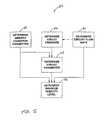
- FIG. 5illustrates a method of determining a maximum humidity level according to an embodiment of the invention.
- FIG. 6illustrates a method of operating the patient treatment system, in accordance with an embodiment of the invention.
- FIG. 1schematically illustrates an exemplary embodiment of a patient treatment system 10 according to the principles of the present invention.
- Patient treatment system 10is capable of providing breathable gas to a patient while automatically controlling the pressure of the breathable gas according to a predetermined mode of ventilation.
- Patient treatment system 10includes a patient circuit 12 that provides the breathable gas to the patient from a gas source.
- the gas sourceis ambient air, but may be other types of sources, as will be described later.
- the breathable gasis introduced into circuit 12 from the gas source at an intake 14 .
- Intake 14may include a port, a vent, or an opening.
- intake 14may include a filter that filters the breathable gas as it is introduced into circuit 12 .
- a pressurizing flow module 16controls the pressure and flow of the gas in circuit 12 from intake 14 to a patient interface 17 where the breathable gas is delivered to an airway of the patient.
- Circuit 12also includes a humidifier 18 that operates to elevate the humidity of the gas in circuit 12 to a selectably controllable circuit humidity level.
- the patient treatment system 10further includes a control module 28 that interfaces with a control interface 30 , memory 32 , and monitor 50 , as will be described in detail later.
- pressurizing flow module 16is illustrated according to one exemplary embodiment of the invention.
- pressurizing flow module 16includes a pressure generator 19 that receives the breathable gas in patient circuit 12 and elevates the pressure of that gas for delivery to the airway of a patient.
- Pressure generator 19is any device, such as a pump, blower, piston, or bellows, that is capable of elevating the pressure of the received breathable gas for delivery to a patient.
- the present inventionalso contemplates that gas other than ambient atmospheric air may be introduced into circuit 12 for delivery to the patient.
- a pressurized canister or tank of gas containing air, oxygen, or other breathable gas mixturecan supply the intake 14 to pressure generator 19 .
- pressure generator 19need not be provided, but instead the breathable gas can by pressurized by the pressure of the canister or tank of pressurized gas itself, with the pressure delivered to the patient being controlled by a pressure regulator.
- pressure generator 19is a blower that is driven at a substantially constant speed during the course of the pressure support treatment to provide the gas in circuit 12 with a substantially constant elevated pressure and/or flow rate.
- control valve 20controls the circuit pressure and/or the circuit flow rate of the gas in circuit 12 downstream from pressurizing flow module 16 .
- control valve 20include at least one valve, such as sleeve or poppet valve, that exhausts gas from circuit 12 as a method of controlling the circuit pressure and circuit flow rate in circuit 12 .
- pressure generator 19is a blower that operates at only one speed
- one or more control settings of control valve 20can be adjusted to provide control over the circuit pressure and the circuit flow rate for the breathable gas in circuit 12 .
- one or more control settings related to the operation of pressure generator 19such as a blower speed
- one or more control settings related to the operation of pressure generator 19are adjusted alone or in combination with the control settings of control valve 20 to control the circuit pressure and the circuit flow rate for the breathable gas delivered to the patient along circuit 12 .
- a circuit pressure and a circuit flow rate close to the desired circuit pressure and circuit flow ratecan be set by adjusting an appropriate operating speed for pressure generator 19 (macro control).
- Fine tuning (micro control) of the circuit pressure and the circuit flow ratecan then be provided by adjusting one or more control settings associated with control valve 20 so that the two, operating together, determine the final circuit pressure for the breathable gas in circuit 12 downstream from pressurizing flow module 16 . If the operation of the pressure generator alone is used to control the pressure or the flow of gas in the patient circuit, control valve 20 can be omitted, as shown in FIG. 3 .
- pressurizing flow module 16includes a pressure/flow sensor 22 .
- Pressure/flow sensor 22is a device, assembly, system, or combination thereof that is capable of outputting a signal indicative of a pressure, a flow, or both, associated with the gas in the patient circuit.
- the pressure of the gas in patient circuit 12is monitored using a conventional pressure sensor.
- the flow of breathable gas output from control valve 20is delivered to pressure/flow sensor 22 , which outputs a signal indicative of the rate of flow of gas in conduit 24 .
- This signalcan be used to determine the instantaneous volume (V) of gas delivered to the patient, the instantaneous flow rate (V′) of such gas to the patient, or both.
- Pressure/flow sensor 22is any device suitable for measuring these parameters, such as a spirometer, pneumotach, variable orifice transducer, differential pressure transducer, or other conventional flow transducer.
- pressure/flow sensor 22is provided within pressurizing flow module 16 , at a location relatively distant from patient interface 17 .
- the present inventioncontemplates locating pressure/flow sensor 22 at any location along circuit 12 as well as at patient interface 17 .
- U.S. Pat. No. 6,017,315the contents of which are incorporated herein by reference, teaches a quantitative flow member that is located at patient interface 17 .
- the pressure/flow sensoris any device capable of measure a parameter indicative of the flow of gas in the patient circuit. It is to be understood that gas flow can be determined by monitoring the operation of pressure generator 19 , such as the voltage, current, or power provided to the blower, its operating speed, etc., all of which vary with the pressure or flow in the patient circuit.
- the present inventionalso contemplates monitoring the operation of control valve 20 , such as the position of the valve, as a means for determining the flow of gas in the patient circuit, for it is known that the position of the valve in a feedback controlled pressure generating module corresponds to the flow of gas in the patient circuit.
- pressure/flow sensor 22can be incorporated into pressure generator 19 , control valve 20 , or both.
- FIG. 3An alternate embodiment of a pressurizing flow module 16 ′ is illustrated in FIG. 3 .
- the embodiment of FIG. 3controls the pressure of breathable gas delivered to the patient based solely on the output of pressure generator 19 .
- the control module 28may control the pressure of breathable gas delivered to the patient by controlling only a motor speed of a blower associated with pressure generator 19 .
- the embodiments of the present inventioncontemplate providing, if desired, ancillary feedback systems, such as a pressure monitor in circuit 12 , motor speed monitor, valve monitor, or pressure generator output monitor that provides feedback data to the control module 28 for controlling the operation of pressurizing flow module 16 .
- conduit 24the flow of breathable gas is carried between the various components in circuit 12 via sections of a conduit 24 .
- some or all of the various sections of conduit 24may be provided by flexible tubing, rigid tubing, or by other members that would provide a conduit for the breathable gas therethrough.
- conduit 24forms all or part of the patient circuit that communicates gas with the airway of the patient.
- Patient interface 17is any appliance, either invasive or non-invasive, such as a nasal mask, nasal/oral mask, total face mask, nasal cannula, endotracheal tube, or tracheal tube, suitable for communicating a supply of breathable gas to the airway of a patient.
- Patient interface assembly 17may include headgear for mounting the appliance on the head of a patient.
- patient interface 17 and/or conduit 24includes a suitable exhaust port 26 for exhausting gas from these components to ambient atmosphere.
- Exhaust port 26is preferably a passive exhaust port in the form of a continuously open port that imposes a flow restriction on the exhaust gas to permit control of the pressure of gas within patient interface 17 .
- exhaust port 26can be an active exhaust port that assumes different configurations to control the exhaust rate.
- suitable exhaust portsare taught, for example, in U.S. Pat. Nos. 5,725,296 and 5,937,855, the contents of which are incorporated herein by reference.
- Control module 28is operatively linked to pressurizing flow module 16 and humidifier 18 .
- the output of sensor 22is provided to control module 28 , which comprises a processor and suitable programming for determining the instantaneous volume (V) of gas delivered to the patient, or the instantaneous flow rate (V′) of such gas to the patient, or both based on the signals from sensor 22 .
- the instantaneous volumecan be determined by integrating the measured flow rate. Because the flow sensor 22 is located relatively far from patient interface 17 , in order to determine the actual flow rate of gas to the patient or the actuation flow rate of gas from the patient, which is considered a negative flow, control module 28 receives the output from sensor 22 as an estimated flow. Control module 28 processes this estimated flow information, for example, by performing leak estimation, to determine the actual flow at the patient's airway, as is known to those skilled in the art.
- control interface 30provides data and commands to control module 28 and outputs, in human perceivable form, any information of interest. For example, commands may be provided at control interface 30 to control module 28 to adjust one or more control settings associated with patient treatment system 10 .
- Control interface 30is any device suitable to provide information and/or commands to control module 28 via an operative link and to present information to the patient, or another user, in a human perceivable format. Examples of a suitable input/output device includes a keypad, keyboard, touch pad, mouse, visual display (e.g., LCD or LED screen), microphone, speaker, switches, button, dials, lamps, or any other devices that allow a user to input information to and receive information from treatment system 10 . Interface 30 can also include hardwired or wireless techniques for communicating information and/or commands with processor 40 , such as a serial port, parallel port, USB port, RS-232 port, smart card terminal, modem port, etc.
- patient circuit 12is a single-limb circuit. It is to be understood, however, that the present invention also contemplates that patient circuit 12 can be a two-limb circuit, which is common in conventional ventilators.
- the first limb in a two-limb circuitlike patient circuit 12 shown in the figures except that it lacks an exhaust port, carries a flow of gas from a source of such gas to the patient.
- the second limb in a two-limb circuitcarries the exhaust gases from the patient to ambient atmosphere.
- an active exhaust port or exhaust valveis provided in the second limb under the control of control module 28 to maintain a desired level of positive end expiratory pressure (PEEP) in the patient.
- PEEPpositive end expiratory pressure
- patient circuit 12 and related componentscan include other conventional devices, such as a heater, bacteria filter, temperature sensor, pressure sensor, and a gas sensor (e.g., a capnometer that measures, monitors, analyzes, etc. the flow of gas to or from the patient).
- a heatere.g., a heater, bacteria filter, temperature sensor, pressure sensor, and a gas sensor (e.g., a capnometer that measures, monitors, analyzes, etc. the flow of gas to or from the patient).
- a gas sensore.g., a capnometer that measures, monitors, analyzes, etc. the flow of gas to or from the patient.
- Control module 28controls the actuation of a control valve associated with pressurizing flow module 16 (e.g., control valve 20 of FIG. 2 ) by adjusting one or more control settings, thereby controlling the circuit pressure, the circuit flow rate, or both of the breathable gas in circuit 12 .
- the pressure of the breathable gasis provided to the patient according to the CPAP, Bi-level, auto-titrating, PAV, C-Flex, Bi-Flex, or PPAP modes of ventilation or pressure support.
- control module 28is suitably programmed with the necessary algorithm or algorithms for calculating the circuit pressure and circuit flow rate to be applied to the patient according to these modes of ventilation.
- Memory 32is optionally provided and can be linked with control module 28 to provide storage for the algorithms or programs provided above, as well as other data associated with system 10 .
- humidifier 18includes a chamber 38 that holds a reservoir of fluid 40 .
- the fluidmay be composed primarily, or entirely, of water.
- the reservoir of fluid 40is heated by a heating element 42 to cause the reservoir of fluid 40 to evaporate, thereby producing vapor within chamber 38 .
- the vapor in chamber 38is delivered to the gas, thereby elevating the humidity of the gas in patient circuit 12 downstream from humidifier 18 .
- the amount by which the humidity level of the gas is increased by humidifier 18depends on the amount of vapor delivered to the gas as it passes through humidifier 18 . This is a function of, among other things, the density of the vapor in chamber 38 , which depends in part on the rate at which the reservoir of fluid 40 is evaporated.
- the degree of the increase in the circuit humidity level of the gas passing through humidifier 18can be controlled via control module 28 by adjusting one or more humidifier parameters that affect the rate of evaporation of the reservoir of fluid 40 , such as the temperature of heating element 42 , the size of chamber inlet 44 , the size of chamber outlet 46 , the amount of fluid in reservoir of fluid 40 , the surface area of reservoir of fluid 40 , the temperature of the reservoir of fluid 40 , or other humidifier parameters.
- the one or more humidity parametersare adjusted by control module 28 via an operative link.
- humidifier 18may include any suitable device for delivering vapor to the gas in circuit 12 to elevate the humidity level of the gas in an adjustable manner.
- any suitable device for delivering vapor to the gas in circuit 12 to elevate the humidity level of the gas in an adjustable mannerfor example, U.S. Pat. No. 5,655,542, the contents of which are incorporated herein by reference, teaches a passive humidifier for use with a PAP device that may be implemented as humidifier 18 in one embodiment.
- humidifier 18includes a sensor 48 that monitors a humidifier parameter.
- sensor 48is associated with heating element 42 and monitors the temperature of heating element 42 .
- sensor 48may instead be disposed within chamber 38 and used to monitor the temperature of the reservoir of fluid 40 .
- Sensor 48communicates information associated with the monitored humidifier parameter to control module 28 via an operative link. It will be appreciated that although humidifier 18 is illustrated as being disposed in circuit 12 downstream from pressurizing flow module 16 , in other embodiments, humidifier 18 may be disposed in an upstream position from pressurizing flow module 16 .
- Patient treatment system 10includes a monitor 50 that is disposed outside of patient circuit 12 .
- Monitor 50monitors one or more ambient condition parameters of the breathable gas prior to the breathable gas being introduced into the patient circuit at intake 14 .
- the ambient condition parameters monitored by monitor 50include an ambient humidity level (via, e.g., a relative humidity sensor, a capacitive humidity sensor, a resistive humidity sensor, etc.) and/or an ambient temperature (via, e.g., a thermometer, a thermostat, a thermocouple, a thermistor, etc.).
- Monitor 50is operatively linked to control module 28 , and communicates information associated with the ambient condition parameters monitored to control module 28 via the operative link.
- FIG. 4illustrates a method 52 of operation of the present invention. Specifically, the method entails predicting the circuit humidity level.
- a determination of one or more ambient condition parametersis made.
- the ambient condition parametersare determined by control module 28 based on information received by control module 28 from monitor 50 .
- the ambient condition parametersmay include, for example, the ambient humidity level, the ambient temperature, and/or the ambient barometric pressure.
- humidity levelas used herein, may include monitoring and/or determinations made with respect to any one of absolute humidity level, relative humidity level, or dewpoint.
- Method 52includes an operation 56 , at which the circuit flow rate of the gas in circuit 12 is determined by control module 28 .
- control module 28determines the circuit flow rate by processing a signal generated by pressure/flow sensor 22 .
- the circuit flow ratemay be determined without monitoring the gas in circuit 12 with a sensor, but rather may be based on one or more control settings, such as a blower speed, a valve control setting, or other control settings.
- the circuit pressure of the gas in circuit 12is determined by control module 28 .
- the circuit pressureis determined based on, for example, a signal generated by a pressure/flow sensor 22 operatively coupled to patient circuit 12 .
- the circuit pressuremay be determined based on one or more control settings, similar to the determination of the circuit flow rate based on control settings as described above, such as the pressure setting to be delivered to the patient.
- Method 52includes an operation 60 , at which one or more circuit parameters of the gas in patient circuit 12 are determined by control module 28 .
- the circuit parametersinclude the circuit temperature and the circuit humidity level upstream from humidifier 18 .
- the parameters of the gasincluding the temperature and the humidity level prior to entering humidifier 18 , are determined because as pressurizing flow module 16 elevates the flow rate and the pressure of the gas, the temperature and humidity level of the gas are indirectly altered due to the change in pressure.
- the circuit parametersmay be determined based on the determination of the ambient condition parameters made by control module 28 via monitor 50 at operation 54 and the determination(s) of the circuit pressure and/or the circuit flow rate made at operations 56 , 58 .
- one or more of the circuit parameters, such as temperaturemay be measured directly via one or more sensors disposed within the circuit.
- one or more humidifier parametersare determined by control module 28 .
- the humidifier parametersare related to the increase in the circuit humidity level applied to the gas in circuit 12 as it passes through humidifier 18 .
- control module 28determines the humidifier parameters based on information related to the temperature of heating element 42 provided by sensor 48 .
- the temperature of heating element 42is associated with the temperature of reservoir of fluid 40 held in chamber 38 , which corresponds to the rate of evaporation of the reservoir of fluid 40 .
- the temperature of heating element 42may be monitored based on a control setting that controls the temperature of heating element 42 .
- the temperature of the reservoir of fluid 40may be monitored directly by a temperature sensor (e.g., thermocouple, thermometer, or other temperature sensing device).
- Method 52includes an operation 64 , at which the circuit humidity level is predicted by control module 28 . This determination is based on a predicted rise in the humidity of the gas as a result of passing through humidifier 18 . As has been outlined above, this rise in the humidity level is dependent on circuit flow rate determined at operation 56 the circuit parameters determined at operation 60 , and the humidifier parameters determined at operation 62 . In one embodiment, the humidity level may be determined based on a look-up table. The values in the look-up table may be derived via an algorithm, or determined experimentally.
- Method 66includes operations 68 , 70 , 72 , and 74 , which correspond to operations 54 , 56 , 58 , and 60 of method 52 , respectively, and generate determinations of the ambient condition parameters, the circuit flow rate, the circuit pressure, and the circuit parameters by control module 28 according to the manner described above with respect to operations 54 , 56 , 58 , and 60 .
- operations 68 , 70 , 72 , and 74are omitted for the sake of brevity.
- the maximum humidity levelis determined.
- the determination of the maximum humidity levelis based on the circuit flow rate determined at operation 70 , the ambient condition parameters determined at operation 68 , and the circuit parameters determined at operation 74 .
- the maximum humidity levelmay be determined based on a look-up table. The values in the look-up table may be derived via an algorithm, or determined experimentally.
- Method 78includes an operation 80 at which the system 10 is activated.
- system 10is activated in response to input received by system 10 via control interface 30 , and includes activating pressurizing flow module 16 and humidifier 18 .
- the present inventionalso contemplates that the patient treatment system can be activated (and deactivated) automatically, for example when the system detects that the patient is breathing into patient interface 17 .
- An example of an auto on/off systemis described in U.S. Pat. No. 6,629,527.
- Method 78includes an operation 82 , at which a target humidity level is determined.
- the target humidity levelis automatically set at the maximum humidity level, which is determined by control module 28 at operation 82 according to method 66 .
- determining the target humidity levelmay include receiving a selected humidity level input to system 10 at control interface 30 .
- the current circuit humidity level downstream of humidifier 18is predicted.
- the circuit humidity levelis predicted by control module 28 according to method 52 .
- the prediction of the current circuit humidity levelis then compared with the target humidity level by control module 28 at an operation 86 . This comparison includes determining if the circuit humidity level is substantially equal to the target humidity level.
- the circuit humidity level and the target humidity levelmay be determined to be substantially equivalent.
- the predetermined rangeincludes circuit humidity levels within range boundaries that are offset from the target humidity level by plus and minus a predetermined amount.
- the predetermined rangemay only include circuit humidity levels within range boundaries wherein one of the range boundaries is set at or near the target humidity level and the other range boundary is set either above or below the target humidity level by a predetermined offset.
- control module 28adjusts one or more humidifier parameters.
- the humidifier parameter that is adjustedis the temperature of heating element 42 .
- the temperature of heating element 42may be adjusted in the appropriate direction (e.g., hotter or cooler) by a predetermined amount, or the amount of adjustment may be based on the degree of the difference in the values of the target humidity level and the circuit humidity level.
- the determination made at operation 90may include determining if a deactivation command has been input to system 10 at control interface 30 .
- the present inventionalso contemplates automatically deactivating the system and/or issuing a deactivation signal if, for example, patient breathing into the patient interface 17 is no longer detected. If no deactivation command has been received by system 10 , then method 78 returns to operations 82 and 84 . If a deactivation command has been received by system 10 , then system 10 is deactivated at an operation 92 .
- Deactivating system 10includes deactivating pressurizing flow module 16 and humidifier 18 . In one embodiment, deactivating system 10 may include deactivating only one or the other of pressurizing flow module 16 and humidifier 18 .
- the humidity level of the gas in the circuitcan be determined without use of a humidity sensor in the circuit.
- the determined humidity level in the circuitcan then be fed back to the processor in a closed loop to enable the patient to set and/or control the humidity level for increased comfort, and optionally without generating excessive condensation in the system.
Landscapes
- Health & Medical Sciences (AREA)
- Emergency Medicine (AREA)
- Pulmonology (AREA)
- Engineering & Computer Science (AREA)
- Anesthesiology (AREA)
- Biomedical Technology (AREA)
- Heart & Thoracic Surgery (AREA)
- Hematology (AREA)
- Life Sciences & Earth Sciences (AREA)
- Animal Behavior & Ethology (AREA)
- General Health & Medical Sciences (AREA)
- Public Health (AREA)
- Veterinary Medicine (AREA)
- Air Conditioning Control Device (AREA)
Abstract
Description
Claims (18)
Priority Applications (1)
| Application Number | Priority Date | Filing Date | Title |
|---|---|---|---|
| US11/481,323US8640696B2 (en) | 2005-07-07 | 2006-07-05 | System and method for determining humidity in a respiratory treatment system |
Applications Claiming Priority (2)
| Application Number | Priority Date | Filing Date | Title |
|---|---|---|---|
| US69713005P | 2005-07-07 | 2005-07-07 | |
| US11/481,323US8640696B2 (en) | 2005-07-07 | 2006-07-05 | System and method for determining humidity in a respiratory treatment system |
Publications (2)
| Publication Number | Publication Date |
|---|---|
| US20080308100A1 US20080308100A1 (en) | 2008-12-18 |
| US8640696B2true US8640696B2 (en) | 2014-02-04 |
Family
ID=40131183
Family Applications (1)
| Application Number | Title | Priority Date | Filing Date |
|---|---|---|---|
| US11/481,323Active2030-11-18US8640696B2 (en) | 2005-07-07 | 2006-07-05 | System and method for determining humidity in a respiratory treatment system |
Country Status (1)
| Country | Link |
|---|---|
| US (1) | US8640696B2 (en) |
Cited By (17)
| Publication number | Priority date | Publication date | Assignee | Title |
|---|---|---|---|---|
| US20130087143A1 (en)* | 2010-06-04 | 2013-04-11 | Koninklijke Philips Electronics N.V. | Automatic humidity control in a pressure support system |
| US20130174841A1 (en)* | 2009-12-23 | 2013-07-11 | Fisher & Paykel Healthcare Limited | Humidified gases delivery apparatus and methods for controlling same |
| US20180250490A1 (en)* | 2014-09-03 | 2018-09-06 | Fisher & Paykel Healthcare Limited | Deterministically controlled humidification system |
| US10426902B2 (en) | 2009-12-23 | 2019-10-01 | Fisher & Paykel Healthcare Limited | Systems for laparoscopic surgery |
| US10709866B2 (en) | 2014-05-13 | 2020-07-14 | Fisher & Paykel Healthcare Limited | Usability features for respiratory humidification system |
| US10828482B2 (en) | 2013-12-20 | 2020-11-10 | Fisher & Paykel Healthcare Limited | Humidification system connections |
| US10905836B2 (en) | 2015-04-02 | 2021-02-02 | Hill-Rom Services Pte. Ltd. | Manifold for respiratory device |
| US10974015B2 (en) | 2012-03-15 | 2021-04-13 | Fisher & Paykel Healthcare Limited | Respiratory gas humidification system |
| US11129956B2 (en) | 2012-04-27 | 2021-09-28 | Fisher & Paykel Healthcare Limited | Usability features for respiratory humidification system |
| US11173272B2 (en) | 2014-05-02 | 2021-11-16 | Fisher & Paykel Healthcare Limited | Gas humidification arrangement |
| US11278689B2 (en) | 2014-11-17 | 2022-03-22 | Fisher & Paykel Healthcare Limited | Humidification of respiratory gases |
| US11324911B2 (en) | 2014-06-03 | 2022-05-10 | Fisher & Paykel Healthcare Limited | Flow mixers for respiratory therapy systems |
| US11351332B2 (en) | 2016-12-07 | 2022-06-07 | Fisher & Paykel Healthcare Limited | Sensing arrangements for medical devices |
| US11511069B2 (en) | 2013-09-13 | 2022-11-29 | Fisher & Paykel Healthcare Limited | Humidification system |
| US11559653B2 (en) | 2014-02-07 | 2023-01-24 | Fisher & Paykel Healthcare Limited | Respiratory humidification system |
| US11801360B2 (en) | 2013-09-13 | 2023-10-31 | Fisher & Paykel Healthcare Limited | Connections for humidification system |
| US12226569B2 (en) | 2009-12-23 | 2025-02-18 | Fisher & Paykel Healthcare Limted | Systems for laparoscopic surgery |
Families Citing this family (27)
| Publication number | Priority date | Publication date | Assignee | Title |
|---|---|---|---|---|
| US8739780B2 (en) | 2005-08-15 | 2014-06-03 | Resmed Limited | Low cost CPAP flow generator and humidifier assembly |
| US11833301B2 (en) | 2005-09-12 | 2023-12-05 | ResMed Pty Ltd | High flow therapy device utilizing a non-sealing respiratory interface and related methods |
| US11458270B2 (en) | 2005-09-12 | 2022-10-04 | ResMed Pty Ltd | High flow therapy device utilizing a non-sealing respiratory interface and related methods |
| US11717174B2 (en) | 2005-09-12 | 2023-08-08 | ResMed Pty Ltd | High flow therapy device utilizing a non-sealing respiratory interface and related methods |
| US11696992B2 (en) | 2005-09-12 | 2023-07-11 | ResMed Pty Ltd | High flow therapy device utilizing a non-sealing respiratory interface and related methods |
| US11497407B2 (en) | 2005-09-12 | 2022-11-15 | ResMed Pty Ltd | High flow therapy device utilizing a non-sealing respiratory interface and related methods |
| US11318267B2 (en)* | 2006-09-12 | 2022-05-03 | ResMed Pty Ltd | High flow therapy device utilizing a non-sealing respiratory interface and related methods |
| MX2010001827A (en)* | 2007-08-14 | 2010-06-01 | Plastiflex Belgium | A respiratory system. |
| US8287506B2 (en) | 2007-10-26 | 2012-10-16 | Electrochemical Oxygen Concepts, Inc. | Apparatus and methods for controlling tissue oxygenation for wound healing and promoting tissue viability |
| US10226610B2 (en) | 2007-10-26 | 2019-03-12 | Electrochemical Oxygen Concepts, Inc. | Apparatus and methods for controlling tissue oxygenation for wound healing and promoting tissue viability |
| US9802022B2 (en)* | 2008-03-06 | 2017-10-31 | Resmed Limited | Humidification of respiratory gases |
| AU2015203636B2 (en)* | 2008-05-27 | 2017-08-31 | Fisher & Paykel Healthcare Limited | Control of humidifier chamber temperature for accurate humidity control |
| AU2009251939B2 (en)* | 2008-05-27 | 2015-08-06 | Fisher & Paykel Healthcare Limited | Control of humidifier chamber temperature for accurate humidity control |
| US20130239965A1 (en)* | 2010-01-15 | 2013-09-19 | Koninklijke Philips Electronics N.V. | Humidification system with signal transmission optimization |
| EP2575944B1 (en) | 2010-06-04 | 2017-02-22 | Koninklijke Philips N.V. | Automatic control of temperature in a patient circuit |
| CN103189089A (en)* | 2010-09-07 | 2013-07-03 | 耐斯特科技有限公司 | Remaining service life indication for gas mask cartridges and canisters |
| US9314582B2 (en)* | 2010-11-23 | 2016-04-19 | Carefusion 2200, Inc. | Humidification system |
| CN102294185B (en)* | 2011-06-28 | 2013-06-05 | 哈尔滨工业大学 | Gas preparation apparatus for preparing gas with imitative human exhaled air ratio and regulation of temperature/humidity, and method thereof |
| US8733348B2 (en)* | 2011-09-30 | 2014-05-27 | Carefusion 207, Inc. | Humidifying respiratory gases |
| US9205220B2 (en) | 2011-09-30 | 2015-12-08 | Carefusion 207, Inc. | Fluted heater wire |
| US10168046B2 (en) | 2011-09-30 | 2019-01-01 | Carefusion 207, Inc. | Non-metallic humidification component |
| CN119280635A (en) | 2015-12-07 | 2025-01-10 | 电化学氧概念公司 | Devices and methods for controlling tissue oxygenation and promoting tissue vitality in wound healing |
| EP3405245A4 (en) | 2016-01-18 | 2019-09-11 | Fisher&Paykel Healthcare Limited | HUMIDIFICATION OF RESPIRATORY GASES |
| JP7301744B2 (en) | 2016-10-11 | 2023-07-03 | フィッシャー アンド ペイケル ヘルスケア リミテッド | How to detect connection errors in humidification systems |
| US10702686B2 (en) | 2017-06-30 | 2020-07-07 | Electrochemical Oxygen Concepts, Inc. | Wound oxygen supply system |
| JP7526199B2 (en) | 2019-03-29 | 2024-07-31 | フィッシャー アンド ペイケル ヘルスケア リミテッド | System and method for detecting misconnections in a humidification system |
| US20220143356A1 (en)* | 2019-06-06 | 2022-05-12 | Vincent Medical (Dong Guoan) Manufacturing Co., Ltd. | Dew point sensor system, method for modulating a humidifier heater plate, and humidifier/medical device containing |
Citations (27)
| Publication number | Priority date | Publication date | Assignee | Title |
|---|---|---|---|---|
| US3659604A (en) | 1970-03-30 | 1972-05-02 | Fisher & Paykel | Humidifying means |
| US4038980A (en) | 1973-11-12 | 1977-08-02 | Imre Fodor | Air humidifiers |
| US4367734A (en) | 1980-08-28 | 1983-01-11 | Dragerwerk Aktiengesellschaft | Y-Fitting in the patient system of respirators |
| US5031612A (en) | 1990-04-24 | 1991-07-16 | Devilbiss Health Care, Inc. | System and method for delivering warm humidified air |
| US5092326A (en) | 1987-11-19 | 1992-03-03 | Winn Bryan D | Apparatus and method for a ventilator system |
| US5163423A (en) | 1990-11-30 | 1992-11-17 | Origin Medical Instrument Co., Ltd. | Humidifier |
| US5368786A (en) | 1992-09-30 | 1994-11-29 | Wisconsin Alumni Research Foundation | Apparatus and methods for humidity control |
| US5429123A (en) | 1993-12-15 | 1995-07-04 | Temple University - Of The Commonwealth System Of Higher Education | Process control and apparatus for ventilation procedures with helium and oxygen mixtures |
| US5468961A (en) | 1991-10-08 | 1995-11-21 | Fisher & Paykel Limited | Infrared gas analyser and humidity sensor |
| US5558084A (en) | 1991-10-04 | 1996-09-24 | Fisher & Paykel Limited | Humidifier with delivery tube condensation preventing structure and control |
| US5769071A (en) | 1995-02-16 | 1998-06-23 | Smiths Industries Plc | Humidifier systems |
| US5988164A (en) | 1995-07-31 | 1999-11-23 | Paluch; Bernard | Breathing circuits with humidity controls |
| US6050260A (en)* | 1996-12-02 | 2000-04-18 | Fisher & Paykel Limited | Humidifier sleep apnea treatment apparatus |
| US6095505A (en) | 1998-07-15 | 2000-08-01 | Pegasus Research Corporation | Patient-end humidifier |
| US6102037A (en)* | 1998-02-28 | 2000-08-15 | Drager Medizintechnik Gmbh | Respiration humidifier |
| US6272933B1 (en) | 1997-06-17 | 2001-08-14 | Fisher & Paykel Limited | Respiratory humidification system |
| EP1138341A2 (en) | 2000-03-21 | 2001-10-04 | FISHER & PAYKEL LIMITED | Humidification apparatus |
| US20020017298A1 (en) | 2000-08-05 | 2002-02-14 | Drager Medical Ag & Co. Kgaa | Evaporation chamber for a respiratory gas humidifier |
| US6349724B1 (en) | 2000-07-05 | 2002-02-26 | Compumedics Sleep Pty. Ltd. | Dual-pressure blower for positive air pressure device |
| US6367472B1 (en) | 1996-05-29 | 2002-04-09 | Dragerwerk Aktiengesellschaft | Respiration humidifier |
| US20020050656A1 (en) | 1998-01-09 | 2002-05-02 | The Holmes Group, Inc. | Modular performance indicator for a humidifier |
| US6435180B1 (en) | 1999-07-01 | 2002-08-20 | J&M Distributors Limited | Method and apparatus for delivering humidified air to a face mask |
| US20020112725A1 (en) | 1999-08-23 | 2002-08-22 | Mohammad Thudor | Humidity controller |
| WO2004020031A1 (en) | 2002-08-30 | 2004-03-11 | Fisher & Paykel Healthcare Limited | Humidification system |
| US20040221844A1 (en)* | 1997-06-17 | 2004-11-11 | Hunt Peter John | Humidity controller |
| US20070137646A1 (en) | 2005-12-01 | 2007-06-21 | Weinstein Lawrence A | Inline vaporizer |
| WO2008024001A1 (en) | 2006-08-25 | 2008-02-28 | Fisher & Paykel Healthcare Limited | Humidifier with internal heating element and heater plate |
Family Cites Families (1)
| Publication number | Priority date | Publication date | Assignee | Title |
|---|---|---|---|---|
| US6425180B1 (en)* | 2001-02-05 | 2002-07-30 | Donald W. Schuenemann | High density electrical connector |
- 2006
- 2006-07-05USUS11/481,323patent/US8640696B2/enactiveActive
Patent Citations (33)
| Publication number | Priority date | Publication date | Assignee | Title |
|---|---|---|---|---|
| US3659604A (en) | 1970-03-30 | 1972-05-02 | Fisher & Paykel | Humidifying means |
| US4038980A (en) | 1973-11-12 | 1977-08-02 | Imre Fodor | Air humidifiers |
| US4367734A (en) | 1980-08-28 | 1983-01-11 | Dragerwerk Aktiengesellschaft | Y-Fitting in the patient system of respirators |
| US5092326A (en) | 1987-11-19 | 1992-03-03 | Winn Bryan D | Apparatus and method for a ventilator system |
| US5031612A (en) | 1990-04-24 | 1991-07-16 | Devilbiss Health Care, Inc. | System and method for delivering warm humidified air |
| US5163423A (en) | 1990-11-30 | 1992-11-17 | Origin Medical Instrument Co., Ltd. | Humidifier |
| US5558084A (en) | 1991-10-04 | 1996-09-24 | Fisher & Paykel Limited | Humidifier with delivery tube condensation preventing structure and control |
| US5468961A (en) | 1991-10-08 | 1995-11-21 | Fisher & Paykel Limited | Infrared gas analyser and humidity sensor |
| US5368786A (en) | 1992-09-30 | 1994-11-29 | Wisconsin Alumni Research Foundation | Apparatus and methods for humidity control |
| US5429123A (en) | 1993-12-15 | 1995-07-04 | Temple University - Of The Commonwealth System Of Higher Education | Process control and apparatus for ventilation procedures with helium and oxygen mixtures |
| US5769071A (en) | 1995-02-16 | 1998-06-23 | Smiths Industries Plc | Humidifier systems |
| US5988164A (en) | 1995-07-31 | 1999-11-23 | Paluch; Bernard | Breathing circuits with humidity controls |
| US6367472B1 (en) | 1996-05-29 | 2002-04-09 | Dragerwerk Aktiengesellschaft | Respiration humidifier |
| US6050260A (en)* | 1996-12-02 | 2000-04-18 | Fisher & Paykel Limited | Humidifier sleep apnea treatment apparatus |
| US6272933B1 (en) | 1997-06-17 | 2001-08-14 | Fisher & Paykel Limited | Respiratory humidification system |
| US20040221844A1 (en)* | 1997-06-17 | 2004-11-11 | Hunt Peter John | Humidity controller |
| US20040079370A1 (en)* | 1997-06-17 | 2004-04-29 | Fisher & Paykel Limited | Respiratory humidification system |
| US20020139367A1 (en) | 1997-06-17 | 2002-10-03 | Fisher & Paykel Limited | Respiratory humidification system |
| US20020129815A1 (en) | 1997-06-17 | 2002-09-19 | Fisher & Paykel Limited | Respiratory humidification system |
| US6349722B1 (en) | 1997-06-17 | 2002-02-26 | Fisher & Paykel Limited | Respiratory humidification system |
| US20020050656A1 (en) | 1998-01-09 | 2002-05-02 | The Holmes Group, Inc. | Modular performance indicator for a humidifier |
| US6102037A (en)* | 1998-02-28 | 2000-08-15 | Drager Medizintechnik Gmbh | Respiration humidifier |
| US6095505A (en) | 1998-07-15 | 2000-08-01 | Pegasus Research Corporation | Patient-end humidifier |
| US6435180B1 (en) | 1999-07-01 | 2002-08-20 | J&M Distributors Limited | Method and apparatus for delivering humidified air to a face mask |
| US20020112725A1 (en) | 1999-08-23 | 2002-08-22 | Mohammad Thudor | Humidity controller |
| US20010050080A1 (en)* | 2000-03-21 | 2001-12-13 | Seakins Paul John | Breathing assistance apparatus |
| EP1138341A2 (en) | 2000-03-21 | 2001-10-04 | FISHER & PAYKEL LIMITED | Humidification apparatus |
| US6349724B1 (en) | 2000-07-05 | 2002-02-26 | Compumedics Sleep Pty. Ltd. | Dual-pressure blower for positive air pressure device |
| US20020017298A1 (en) | 2000-08-05 | 2002-02-14 | Drager Medical Ag & Co. Kgaa | Evaporation chamber for a respiratory gas humidifier |
| WO2004020031A1 (en) | 2002-08-30 | 2004-03-11 | Fisher & Paykel Healthcare Limited | Humidification system |
| JP2005537083A (en) | 2002-08-30 | 2005-12-08 | フィッシャー アンド ペイケル ヘルスケア リミテッド | Humidification system |
| US20070137646A1 (en) | 2005-12-01 | 2007-06-21 | Weinstein Lawrence A | Inline vaporizer |
| WO2008024001A1 (en) | 2006-08-25 | 2008-02-28 | Fisher & Paykel Healthcare Limited | Humidifier with internal heating element and heater plate |
Cited By (35)
| Publication number | Priority date | Publication date | Assignee | Title |
|---|---|---|---|---|
| US11129957B2 (en) | 2009-12-23 | 2021-09-28 | Fisher & Paykel Healthcare Limited | Humidified gases delivery apparatus and methods for controlling same |
| US11980719B2 (en) | 2009-12-23 | 2024-05-14 | Fisher & Paykel Healthcare Limited | Humidified gases delivery apparatus and methods for controlling same |
| US9440042B2 (en)* | 2009-12-23 | 2016-09-13 | Fisher & Paykel Healthcare Limited | Humidified gases delivery apparatus and methods for controlling same |
| US11439775B2 (en) | 2009-12-23 | 2022-09-13 | Fisher & Paykel Healthcare Limited | Systems for laparoscopic surgery |
| US20130174841A1 (en)* | 2009-12-23 | 2013-07-11 | Fisher & Paykel Healthcare Limited | Humidified gases delivery apparatus and methods for controlling same |
| US10220177B2 (en) | 2009-12-23 | 2019-03-05 | Fisher & Paykel Healthcare Limited | Humidified gases delivery apparatus and methods for controlling same |
| US10426902B2 (en) | 2009-12-23 | 2019-10-01 | Fisher & Paykel Healthcare Limited | Systems for laparoscopic surgery |
| US12226569B2 (en) | 2009-12-23 | 2025-02-18 | Fisher & Paykel Healthcare Limted | Systems for laparoscopic surgery |
| US10046136B2 (en)* | 2010-06-04 | 2018-08-14 | Koninklijke Philips N.V. | Automatic humidity control in a pressure support system |
| US20130087143A1 (en)* | 2010-06-04 | 2013-04-11 | Koninklijke Philips Electronics N.V. | Automatic humidity control in a pressure support system |
| US10974015B2 (en) | 2012-03-15 | 2021-04-13 | Fisher & Paykel Healthcare Limited | Respiratory gas humidification system |
| US12350436B2 (en) | 2012-03-15 | 2025-07-08 | Fisher & Paykel Healthcare Limited | Respiratory gas humidification system |
| US11878093B2 (en) | 2012-04-27 | 2024-01-23 | Fisher & Paykel Healthcare Limited | Usability features for respiratory humidification system |
| US11129956B2 (en) | 2012-04-27 | 2021-09-28 | Fisher & Paykel Healthcare Limited | Usability features for respiratory humidification system |
| US12053589B2 (en) | 2013-09-13 | 2024-08-06 | Fisher & Paykel Healthcare Limited | Humidification system |
| US11511069B2 (en) | 2013-09-13 | 2022-11-29 | Fisher & Paykel Healthcare Limited | Humidification system |
| US11801360B2 (en) | 2013-09-13 | 2023-10-31 | Fisher & Paykel Healthcare Limited | Connections for humidification system |
| US11826538B2 (en) | 2013-12-20 | 2023-11-28 | Fisher & Paykel Healthcare Limited | Humidification system connections |
| US10828482B2 (en) | 2013-12-20 | 2020-11-10 | Fisher & Paykel Healthcare Limited | Humidification system connections |
| US11559653B2 (en) | 2014-02-07 | 2023-01-24 | Fisher & Paykel Healthcare Limited | Respiratory humidification system |
| US12397127B2 (en) | 2014-02-07 | 2025-08-26 | Fisher & Paykel Healthcare Limited | Respiratory humidification system |
| US11173272B2 (en) | 2014-05-02 | 2021-11-16 | Fisher & Paykel Healthcare Limited | Gas humidification arrangement |
| US10709866B2 (en) | 2014-05-13 | 2020-07-14 | Fisher & Paykel Healthcare Limited | Usability features for respiratory humidification system |
| US11992622B2 (en) | 2014-05-13 | 2024-05-28 | Fisher & Paykel Healthcare Limited | Usability features for respiratory humidification system |
| US11712536B2 (en) | 2014-06-03 | 2023-08-01 | Fisher & Paykel Healthcare Limited | Flow mixers for respiratory therapy systems |
| US11324911B2 (en) | 2014-06-03 | 2022-05-10 | Fisher & Paykel Healthcare Limited | Flow mixers for respiratory therapy systems |
| US20200269006A1 (en)* | 2014-09-03 | 2020-08-27 | Fisher & Paykel Healthcare Limited | Deterministically controlled humidification system |
| AU2023263503B2 (en)* | 2014-09-03 | 2025-03-06 | Fisher & Paykel Healthcare Limited | Deterministically controlled humidification system |
| US10688272B2 (en)* | 2014-09-03 | 2020-06-23 | Fisher & Paykel Healthcare Limited | Deterministically controlled humidification system |
| US20180250490A1 (en)* | 2014-09-03 | 2018-09-06 | Fisher & Paykel Healthcare Limited | Deterministically controlled humidification system |
| US11278689B2 (en) | 2014-11-17 | 2022-03-22 | Fisher & Paykel Healthcare Limited | Humidification of respiratory gases |
| US10905837B2 (en) | 2015-04-02 | 2021-02-02 | Hill-Rom Services Pte. Ltd. | Respiratory therapy cycle control and feedback |
| US10905836B2 (en) | 2015-04-02 | 2021-02-02 | Hill-Rom Services Pte. Ltd. | Manifold for respiratory device |
| US11992611B2 (en) | 2015-04-02 | 2024-05-28 | Hill-Rom Services Pte. Ltd. | Respiratory therapy apparatus control |
| US11351332B2 (en) | 2016-12-07 | 2022-06-07 | Fisher & Paykel Healthcare Limited | Sensing arrangements for medical devices |
Also Published As
| Publication number | Publication date |
|---|---|
| US20080308100A1 (en) | 2008-12-18 |
Similar Documents
| Publication | Publication Date | Title |
|---|---|---|
| US8640696B2 (en) | System and method for determining humidity in a respiratory treatment system | |
| EP2307082B1 (en) | System and method for determining humidity in a respiratory treatment system | |
| JP7451637B2 (en) | humidification breathing device control | |
| US9669172B2 (en) | Discreet respiratory therapy system | |
| US20220176063A1 (en) | Respiratory humidifier communication systems and methods | |
| US10426914B2 (en) | System and method for adjusting humidification during pressure support therapy | |
| US8671936B2 (en) | Apparatus for supplying respiratory gas and a method for controlling the apparatus | |
| JP6433659B2 (en) | System and method for managing humidified gas for ventilated patients | |
| US9199048B2 (en) | Automatic identification of a patient interface device in a pressure support system | |
| US10279140B2 (en) | Humidity control liquid maximization pressure support device | |
| US20070044799A1 (en) | Modular oxygen regulator system and respiratory treatment system | |
| CA2504359A1 (en) | System for sensing the delivery of gases to a patient | |
| EP2817057B1 (en) | System for determining a target subject interface temperature based on a baseline temperature |
Legal Events
| Date | Code | Title | Description |
|---|---|---|---|
| AS | Assignment | Owner name:RIC INVESTMENTS, LLC, DELAWARE Free format text:ASSIGNMENT OF ASSIGNORS INTEREST;ASSIGNORS:PUJOL, J. RAYMOND;PERROZ JR., WILLIAM;RYBICKI, ROBERT;REEL/FRAME:018081/0579;SIGNING DATES FROM 20060628 TO 20060629 Owner name:RIC INVESTMENTS, LLC, DELAWARE Free format text:ASSIGNMENT OF ASSIGNORS INTEREST;ASSIGNORS:PUJOL, J. RAYMOND;PERROZ JR., WILLIAM;RYBICKI, ROBERT;SIGNING DATES FROM 20060628 TO 20060629;REEL/FRAME:018081/0579 | |
| STCF | Information on status: patent grant | Free format text:PATENTED CASE | |
| FPAY | Fee payment | Year of fee payment:4 | |
| MAFP | Maintenance fee payment | Free format text:PAYMENT OF MAINTENANCE FEE, 8TH YEAR, LARGE ENTITY (ORIGINAL EVENT CODE: M1552); ENTITY STATUS OF PATENT OWNER: LARGE ENTITY Year of fee payment:8 | |
| AS | Assignment | Owner name:RESPIRONICS, INC.., PENNSYLVANIA Free format text:MERGER;ASSIGNOR:RIC INVESTMENTS, LLC;REEL/FRAME:062900/0553 Effective date:20180619 | |
| AS | Assignment | Owner name:PHILIPS RS NORTH AMERICA LLC, PENNSYLVANIA Free format text:CHANGE OF NAME;ASSIGNOR:RESPIRONICS, INC.;REEL/FRAME:063012/0881 Effective date:20201027 | |
| MAFP | Maintenance fee payment | Free format text:PAYMENT OF MAINTENANCE FEE, 12TH YEAR, LARGE ENTITY (ORIGINAL EVENT CODE: M1553); ENTITY STATUS OF PATENT OWNER: LARGE ENTITY Year of fee payment:12 |