US8640086B2 - Graphical user interface system and method for presenting objects - Google Patents
Graphical user interface system and method for presenting objectsDownload PDFInfo
- Publication number
- US8640086B2 US8640086B2US11/647,956US64795606AUS8640086B2US 8640086 B2US8640086 B2US 8640086B2US 64795606 AUS64795606 AUS 64795606AUS 8640086 B2US8640086 B2US 8640086B2
- Authority
- US
- United States
- Prior art keywords
- objects
- graphical
- nodes
- node
- session
- Prior art date
- Legal status (The legal status is an assumption and is not a legal conclusion. Google has not performed a legal analysis and makes no representation as to the accuracy of the status listed.)
- Active, expires
Links
Images


Classifications
- G—PHYSICS
- G06—COMPUTING OR CALCULATING; COUNTING
- G06F—ELECTRIC DIGITAL DATA PROCESSING
- G06F11/00—Error detection; Error correction; Monitoring
- G06F11/36—Prevention of errors by analysis, debugging or testing of software
- G06F11/3698—Environments for analysis, debugging or testing of software
- G—PHYSICS
- G06—COMPUTING OR CALCULATING; COUNTING
- G06F—ELECTRIC DIGITAL DATA PROCESSING
- G06F9/00—Arrangements for program control, e.g. control units
- G06F9/06—Arrangements for program control, e.g. control units using stored programs, i.e. using an internal store of processing equipment to receive or retain programs
- G06F9/44—Arrangements for executing specific programs
- G06F9/451—Execution arrangements for user interfaces
Definitions
- This inventionrelates generally to the field of data processing systems. More particularly, the invention relates to a graphical user interface system and method for presenting object graphs.
- FIG. 1 aTraditional client-server systems employed a two-tiered architecture such as that illustrated in FIG. 1 a .
- Applications 102 executed on the client side 100 of the two-tiered architectureare comprised of a monolithic set of program code including a graphical user interface component, presentation logic, business logic and a network interface that enables the client 100 to communicate over a network 103 with one or more servers 101 .
- a database 104 maintained on the server 101provides non-volatile or “persistent” storage for the data accessed and/or processed by the application 102 .
- the “business logic” component of the applicationrepresents the core program code of the application, i.e., the rules governing the underlying business process (or other functionality) provided by the application.
- the “presentation logic”describes the specific manner in which the results of the business logic are formatted for display on the user interface.
- the “database” 104includes data access logic used by the business logic to store and retrieve data.
- the limitations of the two-tiered architecture illustrated in FIG. 1 abecome apparent when employed within a large enterprise. For example, installing and maintaining up-to-date client-side applications on a large number of different clients is a difficult task, even with the aid of automated administration tools. Moreover, a tight coupling of business logic, presentation logic and the user interface logic makes the client-side code very brittle. Changing the client-side user interface of such applications is extremely hard without breaking the business logic, and vice versa. This problem is aggravated by the fact that, in a dynamic enterprise environment, the business logic may be changed frequently in response to changing business rules. Accordingly, the two-tiered architecture is an inefficient solution for enterprise systems.
- FIG. 1 ba multi-tiered architecture has been developed, as illustrated in FIG. 1 b .
- the presentation logic 121 , business logic 122 and database 123are logically separated from the user interface 120 of the application. These layers are moved off of the client 125 to one or more dedicated servers on the network 103 .
- the presentation logic 121 , the business logic 122 , and the database 123may each be maintained on separate servers, 126 , 127 and 128 , respectively.
- This separation of logical components and the user interfaceprovides a more flexible and scalable architecture compared to that provided by the two-tier model. For example, the separation ensures that all clients 125 share a single implementation of business logic 122 . If business rules change, changing the current implementation of business logic 122 to a new version may not require updating any client-side program code.
- presentation logic 121may be provided which generates code for a variety of different user interfaces 120 , which may be standard browsers such as Internet Explorer® or Netscape Navigator®.
- the multi-tiered architecture illustrated in FIG. 1 bmay be implemented using a variety of different application technologies at each of the layers of the multi-tier architecture, including those based on the Java 2 Enterprise Edition (“J2EE”) standard, the Microsoft .NET standard and/or the Advanced Business Application Programming (“ABAP”) standard developed by SAP AG.
- J2EEJava 2 Enterprise Edition
- Microsoft .NETthe Microsoft .NET
- SAP AGAdvanced Business Application Programming
- the business layer 122which handles the core business logic of the application, is comprised of Enterprise Java Bean (“EJB”) components with support for EJB containers.
- EJBEnterprise Java Bean
- the presentation layer 121is responsible for generating servlets and Java Server Pages (“JSP”) interpretable by different types of browsers at the user interface layer 120 .
- JSPJava Server Pages
- FIG. 2illustrates a typical J2EE application server 200 in which the presentation layer is implemented by a “Web container” 211 and the business layer is implemented by an Enterprise Java Bean (“EJB”) container 201 .
- Containersare runtime environments which provide standard common services 219 , 209 to runtime components.
- JNDIJava Naming and Directory Interface
- Containersalso provide unified access to enterprise information systems 217 such as relational databases through the Java Database Connectivity (“JDBC”) service, and legacy computer systems through the J2EE Connector Architecture (“JCA”) service.
- JDBCJava Database Connectivity
- JCAJ2EE Connector Architecture
- containersprovide a declarative mechanism for configuring application components at deployment time through the use of deployment descriptors.
- each layer of the J2EE architectureincludes multiple containers.
- the Web container 211is itself comprised of a servlet container 215 for processing servlets and a Java Server Pages (“JSP”) container 216 for processing Java server pages.
- JSPJava Server Pages
- the EJB container 201includes three different containers for supporting three different types of enterprise Java beans: a session bean container 205 for session beans, an entity bean container 206 for entity beans, and a message driven bean container 207 for message driven beans.
- J2EE containers and J2EE servicescan be found in R AGAE G HALY AND K RISHNA K OTHAPALLI , SAMS T EACH Y OURSELF EJB IN 21 D AYS (2003) (see, e.g., pages 353-376).
- the computer systems described aboveconsist of many smaller pieces of program code referred to as “objects” which interact each other.
- objectsFor example in a computer program for booking cars at least three objects are required for storing the relevant information: one for the person who makes the booking (name, credit card number etc), one for the booked car (model, engine, class, etc) and another for the booking itself (booking date, return date, etc).
- objectsreference other objects to form very complex object networks.
- information about the structure of an object networkis needed without knowledge about the real data and semantics of the objects in the network.
- structural datasuch as how many people are linked, how clustered the tree is, etc, it is not necessary to know the details about each person—just the properties of the network itself. For that purpose, a consistent, flexible way to represent the object network structure would be desirable.
- a computer-implemented methodcomprises: receiving object graph data from a remote computing system, the object graph data representing characteristics of objects and relationships between objects in object-oriented program code executed on the remote computer system; interpreting the object graph data to determine one or more characteristics of each of the objects; and generating a graphical user interface (“GUI”) comprised of a plurality of graphical nodes arranged in a graph structure, each of the nodes representing one of the objects and the graph structure representing the relationships between the objects, wherein the graphical nodes are rendered with graphical characteristics representing characteristics of the objects which they represent, the graphical characteristics including at least a color and a shape.
- GUIgraphical user interface
- FIG. 1 aillustrates a traditional two-tier client-server architecture.
- FIG. 1 billustrates a prior art multi-tier client-server architecture.
- FIG. 2illustrates a multi-tiered-application server architecture according to the Java 2 Enterprise Edition (“J2EE”) standard.
- J2EEJava 2 Enterprise Edition
- FIG. 3illustrates an exemplary object graph structure.
- FIG. 4illustrates an architecture for processing object graph data according to one embodiment of the invention.
- FIG. 5illustrates a graphical user interface according to one embodiment of the invention.
- FIG. 6illustrates session data within a prior art J2EE application server architecture.
- FIG. 7illustrates a hierarchical session domain architecture according to one embodiment of the invention.
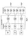
- FIG. 8illustrates an exemplary set of session objects.
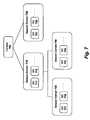
- FIG. 9 aillustrates hierarchical session domains for the session object in FIG. 8 .
- FIG. 9 billustrates session domains for an HTTP session context.
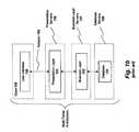
- FIG. 10illustrates data contained within one embodiment of a session domain.
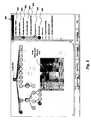
- FIG. 11illustrates a session/cache object graph service employed in one embodiment of the invention.
- FIGS. 12 a - cillustrate a method for measuring differences in memory consumption between objects.
- FIG. 13illustrates an application server architecture according to one embodiment of the invention.
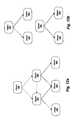
- FIG. 3illustrates an exemplary network of objects 300 - 305 which will be used to describe the various embodiments of the invention.
- object 300references objects 301 and 302 .
- object 300points to objects 301 and 302 (e.g., object 300 may include object 301 , 302 instances as its properties).
- the contained object stateis part of the state of the object—container.
- object 302references objects 301 and 304 - 305 and object 301 references objects 303 - 304 .
- information about the structure of an object networksuch as the one shown in FIG. 3 may be needed without the need for the data and semantics of the objects themselves.
- information related to how each of the objects reference one anothermay be needed rather than the underlying data contained within the objects. In these situations, it is inefficient to transfer all of the data when all that is required is information related to the relationships between the objects.
- one embodiment of the inventionanalyzes object oriented program code and generates a math graph structure to represent the object network.
- the math graph structuremay then be viewed within a visualization tool and/or stored within a mass storage device (as described below).
- the graph structureconsists of one or many “nodes,” each of which represents an object, and zero or many “arcs” (such as arcs 310 ) between the nodes.
- an oriented graphis used because Java object “has a” relationships are parent-child relationships (e.g., a car “has a” make, model, year, and engine).
- every object in computer memoryis represented by one graph node and every object-to-object relationship is represented by one arc.
- FIG. 4illustrates one embodiment of an architecture for performing the foregoing operations.
- a local computer system 411requests object graph information related to object-oriented program code 402 executed on a remote computer system 410 .
- An object graph processing service 404extracts information from the object-oriented program code 402 to generate the object graph and other types of data described herein. The object graph and other data are then transmitted over a network to the requesting computer system 411 .
- Object graph interpreter logic 406 on the requesting computer system 411interprets the serialized object graph and other data to graphically display the results within an object graph graphical user interface 408 sometimes referred to herein as a “visualization tool” (such as the one described below).
- the object graph and other datamay be stored within a storage medium 409 such as a file system or database for later retrieval and viewing.
- the object graph processing logic 404generates and/or collects additional information about objects (nodes) and references (arcs) and transmits the additional information with the object graph information. For example, in one embodiment, the following additional information is generated and/or collected:
- the “memory size” of each objectThis is the relative amount of random access memory consumed by each object.
- the object graph processing logic 404calculates the memory size in terms of a weighted value rather than an absolute value.
- a different weighted valueis assigned to each of the generic types within the object (e.g., based on the relative memory consumption of those types). For example, an integer (INT) may be assigned a weight of 4 whereas a Boolean type may be assigned a weight of 1.
- Various other weightsmay be assigned to other generic types including, for example, char, float, double, byte, short, long and string.
- the object's unique identification code for the graph structureIn one embodiment, the object graph processing logic 404 assigns each object an integer value which uniquely identifies the object within the graph structure.
- the reference namei.e., the class field name.
- transient fieldis one which is neither serialized or persisted.
- the graph structure and additional information related to the object networkare then serialized and transmitted as metadata to a requesting client.
- Thisis advantageous because the graph structure and additional information can be observed as any other graph object using various different types of graph visualization tools. It can also be transmitted over a network such as the Internet (without sending the actual objects and data). It may also be saved on disk in a specified file type (e.g., a text/Extensible Markup Language (XML) file) or as a Java serialized object file for later observation.
- XMLtext/Extensible Markup Language
- the object graph processing logic 404may format and store the object graph data is a variety of ways while still complying with the underlying principles of the invention. For example, both list structures and matrix structures may be used, or a combination of both. List structures are often used for sparse graphs as they have smaller memory requirements whereas matrix structures provide faster access but may consume significant amounts of memory if the graph is very large.
- List structure typesmay include an incidence list structure or an adjacency list structure.
- the edgesare represented by an array containing pairs (ordered if directed) of nodes (that the edge connects) and eventually weight and other data.
- each nodealso sometimes referred to as a “vertex”
- each nodehas a list of which vertices it is adjacent to. This causes redundancy in an undirected graph: for example, if vertices A and B are adjacent, A's adjacency list contains B, while B's list contains A.
- Adjacency queriesare faster, at the cost of extra storage space.
- Matrix structuresmay include an incidence matrix structure in which the graph is represented by a matrix of E (edges) by V (vertices), where [edge, vertex] contains the edge's data and/or an adjacency matrix which is an N by N matrix, where N is the number of vertices in the graph. If there is an edge from some vertex X to some vertex Y, then the element M x,y is 1; otherwise it is 0. This type of matrix makes it easier to locate subgraphs, and to reverse graphs if needed.
- Other possible matrix typesinclude a Laplacian matrix, Kirchhoff matrix, admittance matrix and a distance matrix.
- one embodiment of the inventionemploys a unique graphical visualization tool to observe the object graph and data.
- a visualization tool 408is illustrated in FIG. 5 .
- the graphis drawn as a tree using the selected node 520 as the root.
- the visualization tool 408renders each of the child nodes further up in the hierarchy before their children (i.e., it employs a breadth-first scan).
- the underlying principles of the inventionare not limited to the order in which the nodes are rendered. If a node is referenced more than once the visualization tool 408 renders it each time as a child node but does not traverse its sub-tree more than once. One reason for this is that it avoids cyclic dependencies and potentially endless drawing.
- the visualization tool 408employs different shapes, colors and graphics to indicate different types of nodes and arcs.
- the visualization tooluses a different filling color for nodes referenced once or many times.
- an orange filling coloris used to identify nodes referenced mode than once, as indicated by entry 503 in the legend window 500
- a yellow filling coloris used to identify nodes referenced only once.
- a green filing coloris used to identify “dummy” nodes 507 .
- Dummy nodesare used to improve system performance when working with extremely large graphs.
- a particular object graphmay be very large (e.g., over 1 Gbyte) and may include hundreds of thousands of nodes. In this case, it may take a significant amount of time to traverse and render the entire graph.
- the object graph processing logic 404 and/or the visualization tool 408may stop rendering and insert dummy nodes at the lowest level of the graph structure. The remainder of the graph structure may be drawn upon user request (e.g., by selecting one or more of the dummy nodes).
- nodes without childrenare circular, as indicated by legend entry 501
- nodes with childrenare square with curved corners, as indicated by legend entry 502 .
- different shape contour colorsare used to mark nodes having different properties. For example, a light red contour color is used for nodes which are not shareable, as indicated by legend entry 504 , and a dark red contour color is used for nodes which have children which are non-shareable, as indicated by legend entry 505 .
- Various different contour colorsmay be used to identify different node properties (e.g., serializable nodes may be assigned another contour color).
- the underlying principles of the inventionare not limited to any particular shapes and/or colors.
- the visualization tool 408uses a graphic indicating multiple overlayed nodes for “compound” nodes.
- a compound nodeis an array of nodes of the same type (class).
- the visualization tool 408appends a label on each node.
- the labelcomprises the identification code assigned to each node.
- various other and/or additional informationmay be displayed including, for example, the node weight and/or the percentage of the node's parent weight.
- the visualization tool 408generates the tree dynamically, in response to user input. For example, the visualization tool 408 may expand/collapse the tree upon selection of a node. In addition, in one embodiment, the visualization tool 408 skips certain nodes which do not meet a user-specified criteria (e.g., displaying only nodes which are not shareable). In one embodiment, the visualization tool 408 skips nodes from a given type (class) (class fields with a given name, etc).
- the visualization tool 408displays the additional data collected for each node in response to user input.
- a node information window 510is generated when the user moves a cursor over a particular node.
- the node information window 510may include any of the information described herein including, for example, the node ID, the type, the relative weight (i.e., “Native Size”), and whether the node is shareable.
- additional metadata related to each of the object referencesis generated and/or collected such as the reference name (i.e., the class field name); an indication as to whether the reference is a transient field in Java terms; and the identity of two nodes initiating this relationship.
- This informationmay then be visually displayed within the visualization tool. For example, as indicated in FIG. 5 , lines representing transient references may be provided in a different color than those for standard references.
- Various other graphical featuresmay be employed to convey information about object relationships (e.g., such as a dotted line for unexplored node references).
- the assignee of the present applicationhas developed advanced, hierarchical architectures for managing session objects and cache objects. See, e.g., Session Management Within a Multi-Tiered Enterprise Network, Ser. No. 11/025,200, Filed Dec. 28, 2004, for session object management and Distributed Cache Architecture, Ser. No. 11/025,714, Filed Dec 28, 2005, for cache management.
- Session Management Within a Multi-Tiered Enterprise NetworkSer. No. 11/025,200, Filed Dec. 28, 2004, for session object management and Distributed Cache Architecture, Ser. No. 11/025,714, Filed Dec 28, 2005, for cache management.
- Each of these co-pending patent applicationsis assigned to the assignee of the present application and is incorporated herein by reference.
- An application servermanages session data associated with each client interaction.
- the session datadefines the current conversational state between the client and the application server. For example, if the user is purchasing books from an online bookstore, the session data may define the current state of the user's “shopping cart” (e.g., the books the user has selected for purchase). Similarly, if the user is logged in to a particular Web portal (e.g., “My Yahoo”), the session data may define the state of the Web pages opened in the user's Web browser.
- a particular Web portale.g., “My Yahoo”
- HTTPhypertext transfer protocol
- a single client 630 request from a Web browseran hypertext transfer protocol (HTTP) session object 641 (e.g., an instance of javax.servlet.HttpSession) containing HTTP session data is managed within the Web container 640 and (depending on the type of application) multiple session beans 651 - 653 may be managed within the EJB container 650 .
- HTTPhypertext transfer protocol
- Additional HTTP session objects 642 and session beans 654 - 655may be managed concurrently to define the conversational state with additional clients 631 for the same application (e.g., the shopping cart application) or other applications (e.g., a “search” application).
- the state of any given set of applications such as the user's shopping cartmay be spread across multiple containers.
- session management logicemploys a hierarchical structure for storing different types of related session data within each enterprise application (e.g., HTTP sessions, session EJBs, etc).
- session management layergroups related session objects within a logical hierarchy.
- session context object 700At the top of the hierarchy is a session context object 700 .
- Session domainsare the base configurable objects within the session hierarchy and are positioned beneath the session context 700 .
- the session domainsrepresent abstract storage units for sessions that have similar characteristics (e.g., similar life cycles, applications, etc).
- session objects 711 and 712are managed within session domain 710
- session objects 721 and 722are managed within session domain 720 .
- Both session domains 710 and 720are positioned directly beneath the session context 700 .
- each session domain 710 and 720contains session objects related to different applications.
- session domain 710may contain session objects related to a “shopping cart” application and session domain 720 may contain session objects related to a “calculator” application.
- Two additional session domains 730 and 740are logically positioned beneath session domain 710 within the hierarchy.
- these session domains 730 and 740include session objects 731 , 732 and 741 , 742 , respectively, from the same application associated with session domain 710 .
- session domains 730 and 740include session objects related to the shopping cart application.
- a different session context 700 and associated hierarchy of session domainsis maintained by session management logic for each layer of the application server.
- This embodimentwill be described using the example illustrated in FIG. 8 in which a plurality of session objects are managed for two different applications, identified as applications “A” and “B.”
- the conversational state between client 830 and application Ais maintained via three session bean objects 801 - 803 within the EJB container 842 ; an HTTP session object 811 within the Web container 840 ; and two portal session objects 820 - 821 within the enterprise portal container.
- the conversational state between client 831 and application Ais maintained via two session bean objects 804 , 806 , one HTTP session object 812 , and one portal session object 822 .
- the conversational state between client 832 and application Bis maintained via two session bean objects 807 - 808 , one HTTP session object 813 , and one portal session object 823 .
- session bean objects 801 and 804are instances of a particular session bean, “EJB A,” and session bean objects 802 and 806 are instances of another session bean, “EJB B.”
- Session bean objects 803 , 807 and 808are instances of session beans C, D and E, respectively.
- the enterprise portal container 841is built on top of the Web container 840 .
- a single HTTP session object 811may be related to multiple portal session objects 821 , 821 , which store user-specific session data for a plurality of user-specific Web content (e.g., Web pages) generated during the session.
- user-specific Web contente.g., Web pages
- a single HTTP session object 811is managed within the Web container 840 and separate portal session data related for each individual window of the user's browser is stored within the portal session objects 820 - 821 .
- the HTTP session object 811manages session data related to the entire user session with the application server, whereas the portal session objects store session data for specific pages generated during the session (e.g., “My Yahoo” pages on the “Yahoo” Website).
- each different type of session object shown in FIG. 8is managed within a session domain under a different context.
- a session domainFor example, as illustrated in FIG. 9 a , separate session domains 910 and 920 , are maintained for applications A and B, respectively, under session bean context 900 .
- a separate EJB session domainis used to store and manage session instances for each session bean of each application.
- session domain 910session domain 930 associated with EJB A stores session objects 501 , 504 which are instances of session bean A; session domain 940 associated with EJB B stores session objects 502 , 506 which are instances of session bean B; and session domain 950 associated with EJB C stores session objects 503 which are instances of session bean C.
- session domain 960 associated with EJB Dstores session objects 507 which are instances of session bean D
- session domain 970 associated with EJB Estores session objects 508 which are instances of session bean E.
- HTTP session domains 911 and 921 associated with applications A and B, respectivelyare managed under an HTTP session context 901 .
- the HTTP session domainsstore session data associated with each applications' HTTP sessions. For example, HTTP session objects 511 and 512 are stored within the session domain 911 for application A, and HTTP session object 513 is stored within the session domain 921 for application B.
- portal session domains associated with applications A and B, respectivelyare managed under an application portal session context 902 .
- the portal session domainsstore portal session objects containing portal data associated with each application.
- portal session objects 820 - 822are stored under the portal session domain for application A
- portal session object 823is stored under the session domain for application B.
- FIG. 10illustrates additional details related to the configuration of each session domain 1000 according to one embodiment of the invention.
- each session domain 1000includes a set of configuration policy objects 1003 , a set of local storage attributes 1002 and a set of global storage attributes 1001 .
- the configuration policy objects 1003define the behavior of each session domain.
- the configuration policies implemented by the policy objectsinclude, but are not limited to, a “thresholds” policy for setting limits on the number of sessions objects which are stored within each domain. For example, one session object may be joined to one or more session requests based on the thresholds policy.
- a session access policyis implemented which allows the application or other entity which created the session domain (the “domain owner”) to restrict or otherwise influence session access. For example, the domain owner may prevent multithreaded session access via the session access policy.
- the configuration policy 1003further includes a session invalidation policy which defines the behavior of the session object in the case of session invalidation. For example, as described in greater detail below, in one embodiment, transparent session objects are employed under certain conditions.
- inactive sessionsmay be stored to persistent storage (e.g., the database or file system) and reactivated at a later time in response to subsequent requests.
- a persistence policyis also implemented within the configuration policy objects 1003 to define whether persistent storage should be used and, if so, the particular type of persistent storage that should be used.
- Session persistence typesmay include, but are not limited to, in-memory session persistence (i.e., session objects within the domain are stored within the memory of a single process); in-memory replication persistence (i.e., session object state is stored within a server process memory and is replicated to other server processes); database-based persistence (i.e., the session objects are stored in the database and may be shared across server processes); file system persistence (i.e., sessions are stored within a directory of the file system and can be shared across processes); and cookie-based persistence (i.e., session data is stored within the client in a cookie). It should be noted, however, that the underlying principles of the invention are not limited to any particular set of configuration properties.
- the global storage attributes 1001 of each session domain 1000define attributes of the session domain which are shared across different virtual machines (e.g., different instances of the session domain implemented on different virtual machines).
- the global session attributesmay specify that all sessions within the particular domain 1000 have the same expiration time (e.g., become inactive/invalid after a period of non-responsiveness from a client).
- EJB application descriptorsmay be parsed once and shared between each of the EJB domains located under the session bean context 900
- Web application descriptorsmay be parsed only once and shared between each of the session objects located under the HTTP session context 901 .
- global storage attributesare used only in a shared memory implementation (i.e., in which virtual machines 321 - 325 share session objects via shared memory 340 - 341 as described herein).
- global attributesare identified in shared memory using a unique global attribute name.
- the local storage attributes 1002 of the session domaindefine session attributes which are specific to each individual virtual machine (i.e., they are container-specific). For example, if a particular virtual machine relies on a socket connection to a particular remote server, then this information may be provided within the local storage attributes. Local storage attributes may also include specific references to files within the file system/database and specific references to database connections. In an embodiment which does not employ a shared memory implementation, all attributes of the session domain 1000 are stored within the local storage attributes 1002 .
- the different containerscan use the local storage attributes 1002 to keep certain attributes banded to each concrete server process.
- the HttpSessionincludes the method javax.servlet.ServletContext getServletContext( ).
- ServletContextcan not be shared between different virtual machines because it maintains references to different resources that are local for the concrete server process.
- the Web containerbinds the ServletContext as a local attribute for the session domain.
- the getServletContext( ) methodis implemented to provide a lookup of this attribute from the SessionDomain. Using this technique, the getServletContext( ) will return different objects based on the server process where the session is activated.
- one embodiment of the inventionuses the object graph processing techniques described herein for generating session and cache object graphs and extracting associated data. For example, in one embodiment, object graphs are generated to represent the hierarchical session domains described above.
- FIG. 11illustrates one embodiment of an architecture for performing these operations.
- This embodimentincludes a session/cache object graph service 1004 for generating object graph data related to the session object network 1102 and a cache object network 1103 .
- both the session object network 1102 and the cache object network 1103are executed within a J2EE engine 1110 .
- a local computer system 411requests object graph information related to the session object network 1102 and/or the cache object network 1103 .
- the session/cache object graph service 1004extracts information from the session object network 1102 and the cache object network 1103 to generate an object graph representing the networks as well as the other types of data described herein (e.g., memory size, type, each object's identification code, etc).
- the object graph and other dataare then serialized and transmitted over a network to the requesting computer system 411 .
- Object graph interpreter logic 406 on the requesting computer system 411interprets the serialized session/cache object graphs and other data to graphically display the results within a the visualization tool 408 .
- the object graph and other datamay be stored within a storage medium 409 such as a file system or database for later retrieval and viewing.
- a storage medium 409such as a file system or database for later retrieval and viewing.
- Every object within an object-oriented computer programconsumes a different amount of a computer's memory. Even objects of the same type can consume different amounts. For example, in a rental car reservation system, if two different people book cars, the object for the person with the longest name will consume more memory for its data presentation. Moreover, the fact that objects may reference other objects makes the problem of measuring memory consumption more difficult.
- each “booking” objectholds references to the “person” and “car” objects related to the bookings. Consequently, one object (reservation) holds references to two other objects (person and car). This gets even more complicated when two objects are referencing each other. For example, in an implementation for managing human resources, each “manager” object holds references for its “employer” objects and every “employer” object holds references to its “manager” objects.
- the “characteristic” data for each objectis identified (which is not referenced directly by other objects) and the memory difference between the “characteristic” data is measured.
- the objects and their referencesare represented as math graph structures, generated as described above.
- FIG. 12 aillustrates an example using the object relationships previously illustrated in FIG. 3 .
- an attemptwill be made to measure the difference in memory consumed between nodes 301 and 302 .
- Node 302references node 305 which is characteristic data for it, and node 301 references node 303 that is not referenced directly from node 302 .
- the memory consumption difference between node 302 and node 301is the difference between node 305 and node 303 and the difference of the memory taken by node 302 and node 301 themselves.
- FIG. 12 cOne embodiment of a method for measuring the memory consumption difference between two nodes is illustrated in FIG. 12 c .
- all incoming references to both nodesare removed. This is indicated in FIG. 12 a by arrows with dotted lines.
- the resulting sub-graphsare built from both nodes, as indicated in FIG. 12 b .
- the sum of the memory consumed by each node in the sub-graphis calculated for both sub-graphs. In one embodiment, this is calculated by summing the weights of the node and it's children.
- the memory consumption of node 301is equal to the combined memory consumption of nodes 301 , 303 and 304 .
- the memory consumption of node 302is the is equal to the combined memory consumption of nodes 302 , 304 and 304 .
- the difference between the sums of the memory consumption for nodes 301 and 302is calculated by subtracting the sums.
- delta ( 301 , 302 )nativeSize( 301 )+nativeSize( 303 )+nativeSize( 304 ) ⁇ nativeSize( 302 ) ⁇ nativeSize( 304 ) ⁇ nativeSize( 305 )
- delta ( 301 , 302 )nativeSize( 301 )+nativeSize( 303 ) ⁇ nativeSize( 302 ) ⁇ nativeSize( 305 ).
- the difference between the memory consumed by two objectsmay be determined and, more specifically, the difference between “unique” parts of memory consumed by these objects.
- the object graphis so complex that each node references directly or indirectly (e.g., through a child) any other node. In these cases, while it is not possible to say in general which node takes less memory, the “delta” measure between the two nodes may still be used.
- node 302holds memory of node 303 because it has a reference to 302 which has reference to 303 . It also holds a reference to node 305 .
- the delta between these two objects 301 and 302depends more on the size of object 303 minus the size of object 305 . This, if 301 is bigger using the delta function we will examine its graph and determine that it is because of node 303 . Consequently, optimizing its memory (for node 303 ) will lead to optimizing the memory taken by 301 and 302 .
- FIG. 13A system architecture on which embodiments of the invention may be implemented is illustrated in FIG. 13 .
- the architectureincludes a plurality of application server “instances” 1301 and 1302 .
- the application server instances 1301 and 1302each include a group of worker nodes 1312 - 1314 and 1315 - 1316 (also sometimes referred to herein as “server nodes”), respectively, and a dispatcher 1311 and 1312 , respectively.
- the application server instances 1301 , 1302communicate through a central services instance 1300 using message passing.
- the central services instance 1300includes a locking service and a messaging service (described below).
- the combination of all of the application server instances 1301 and 1302 and the central services instance 1300is referred to herein as a “cluster.” Although the following description will focus solely on instance 1301 for the purpose of explanation, the same principles apply to other instances within the cluster.
- the worker/server nodes 1312 - 1314 within instance 1301provide the business and presentation logic for the network applications supported by the system including, for example, the Web container 211 and the EJB container 201 functionality described herein.
- Each of the worker nodes 1012 - 1014 within a particular instancemay be configured with a redundant set of programming logic and associated data, represented as virtual machines 1321 - 1323 in FIG. 13 .
- the dispatcher 1311distributes service requests from clients to one or more of the worker nodes 1312 - 1314 based on the load on each of the servers. For example, in one embodiment, the dispatcher maintains separate queues for each of the worker nodes 1312 - 1314 in a shared memory 1340 .
- the dispatcher 1311fills the queues with client requests and the worker nodes 1312 - 1314 consume the requests from each of their respective queues.
- the client requestsmay be from external clients (e.g., browser requests) or from other components/objects within the instance 1301 or cluster.
- the worker nodes 1312 - 1314may be Java 2 Enterprise Edition (“J2EE”) worker nodes which support Enterprise Java Bean (“EJB”) components and EJB containers (at the business layer) and Servlets and Java Server Pages (“JSP”) (at the presentation layer).
- J2EEJava 2 Enterprise Edition
- the virtual machines 1321 - 1325implement the J2EE standard (as well as the additional non-standard features described herein). It should be noted, however, that certain high-level features described herein may be implemented in the context of different software platforms including, by way of example, Microsoft .NET platforms and/or the Advanced Business Application Programming (“ABAP”) platforms developed by SAP AG, the assignee of the present application.
- J2EEJava 2 Enterprise Edition
- SAP AGAdvanced Business Application Programming
- a object graph processing service 1330such as the one described above may be executed across each of the instances 1301 , 1302 .
- the object graph processing service 1330implements the various object graph processing techniques described herein.
- the central services instance 1300includes a messaging service and a locking service.
- the message serviceallows each of the servers within each of the instances to communicate with one another via a message passing protocol. For example, messages from one server may be broadcast to all other servers within the cluster via the messaging service (e.g., such as the cache configuration messages described below). Alternatively, messages may be addressed directly to specific servers within the cluster (i.e., rather than being broadcast to all servers).
- the locking servicedisables access to (i.e., locks) certain specified portions of configuration data and/or program code stored within a central database 1345 .
- the locking servicelocks data on behalf of various system components which need to synchronize access to specific types of data and program code.
- the central services instance 1300is the same central services instance as implemented within the Web Application Server version 6.3 and/or 6.4 developed by SAP AG.
- SAP AGWeb Application Server version 6.3 and/or 6.4 developed by SAP AG.
- the underlying principles of the inventionare not limited to any particular type of central services instance.
- one embodiment of the inventionshares objects across virtual machines 1321 - 1325 .
- objectssuch as session objects which are identified as “shareable” are stored within a shared memory region 1340 , 1341 and are made accessible to multiple virtual machines 1321 - 1325 .
- Creating new object instances from scratch in response to client requestscan be a costly process, consuming processing power and network bandwidth.
- sharing objects between virtual machines as described hereinimproves the overall response time of the system and reduces server load.
- a shared memory area 1340 , 1341 or “heap”is used to store data objects that can be accessed by multiple virtual machines 1321 - 1325 .
- the data objects in a shared memory heapshould generally not have any pointers or references into any private heap (e.g., the private memory regions/heaps of the individual virtual machines). This is because if an object in the shared memory heap had a member variable with a reference to a private object in one particular virtual machine, that reference would be invalid for all the other virtual machines that use that shared object.
- this restrictioncan be thought of as follows: For every shared object, the transitive closure of the objects referenced by the initial object should only contain shared objects at all times. Accordingly, in one implementation of the invention, objects are not put into the shared memory heap by themselves—rather, objects (such as the scheduling analysis module 402 and scheduling file 404 described above) are put into the shared memory heap in groups known as “shared closures.”
- a shared closureis an initial object plus the transitive closure of all the objects referenced by the initial object.
- Embodiments of the inventionmay include various steps as set forth above.
- the stepsmay be embodied in machine-executable instructions which cause a general-purpose or special-purpose processor to perform certain steps.
- these stepsmay be performed by specific hardware components that contain hardwired logic for performing the steps, or by any combination of programmed computer components and custom hardware components.
- Elements of the present inventionmay also be provided as a machine-readable medium for storing the machine-executable instructions.
- the machine-readable mediummay include, but is not limited to, flash memory, optical disks, compact disc read-only memories (CD-ROMs, digital video disc read-only memories (DVD ROMs, random access memories (RAMs, erasable programmable read-only memories (EPROMs, electrically erasable programmable read-only memories (EEPROMs), magnetic or optical cards, propagation media or other type of machine-readable media suitable for storing electronic instructions.
- the present inventionmay be downloaded as a computer program which may be transferred from a remote computer (e.g., a server) to a requesting computer (e.g., a client) by way of data signals embodied in a carrier wave or other propagation medium via a communication link (e.g., a modem or network connection).
- a remote computere.g., a server
- a requesting computere.g., a client
- a communication linke.g., a modem or network connection
Landscapes
- Engineering & Computer Science (AREA)
- Theoretical Computer Science (AREA)
- Software Systems (AREA)
- Physics & Mathematics (AREA)
- General Engineering & Computer Science (AREA)
- General Physics & Mathematics (AREA)
- Computer Hardware Design (AREA)
- Quality & Reliability (AREA)
- Human Computer Interaction (AREA)
- Information Retrieval, Db Structures And Fs Structures Therefor (AREA)
- Stored Programmes (AREA)
Abstract
Description
Claims (18)
Priority Applications (3)
| Application Number | Priority Date | Filing Date | Title |
|---|---|---|---|
| US11/647,956US8640086B2 (en) | 2006-12-29 | 2006-12-29 | Graphical user interface system and method for presenting objects |
| PCT/EP2007/010883WO2008080526A1 (en) | 2006-12-29 | 2007-12-12 | Graphical user interface system and method for presenting objects |
| EP07856631AEP2115590A1 (en) | 2006-12-29 | 2007-12-12 | Graphical user interface system and method for presenting objects |
Applications Claiming Priority (1)
| Application Number | Priority Date | Filing Date | Title |
|---|---|---|---|
| US11/647,956US8640086B2 (en) | 2006-12-29 | 2006-12-29 | Graphical user interface system and method for presenting objects |
Publications (2)
| Publication Number | Publication Date |
|---|---|
| US20080163124A1 US20080163124A1 (en) | 2008-07-03 |
| US8640086B2true US8640086B2 (en) | 2014-01-28 |
Family
ID=39281791
Family Applications (1)
| Application Number | Title | Priority Date | Filing Date |
|---|---|---|---|
| US11/647,956Active2031-01-25US8640086B2 (en) | 2006-12-29 | 2006-12-29 | Graphical user interface system and method for presenting objects |
Country Status (3)
| Country | Link |
|---|---|
| US (1) | US8640086B2 (en) |
| EP (1) | EP2115590A1 (en) |
| WO (1) | WO2008080526A1 (en) |
Cited By (39)
| Publication number | Priority date | Publication date | Assignee | Title |
|---|---|---|---|---|
| US9083579B1 (en)* | 2012-09-28 | 2015-07-14 | Emc Corporation | Stateless services in content management clients |
| US9311082B2 (en) | 2006-12-29 | 2016-04-12 | Sap Se | System and method for processing graph objects |
| US20160117322A1 (en)* | 2014-10-27 | 2016-04-28 | Tata Consultancy Services Limited | Knowledge representation in a multi-layered database |
| US9665471B1 (en)* | 2013-10-22 | 2017-05-30 | The Mathworks, Inc. | Program code interface for providing program code and corresponding results of evaluating the program code |
| US9935851B2 (en) | 2015-06-05 | 2018-04-03 | Cisco Technology, Inc. | Technologies for determining sensor placement and topology |
| US9967158B2 (en) | 2015-06-05 | 2018-05-08 | Cisco Technology, Inc. | Interactive hierarchical network chord diagram for application dependency mapping |
| US20180137667A1 (en)* | 2016-11-14 | 2018-05-17 | Oracle International Corporation | Graph Visualization Tools With Summary Visualization For Very Large Labeled Graphs |
| US10033766B2 (en) | 2015-06-05 | 2018-07-24 | Cisco Technology, Inc. | Policy-driven compliance |
| US10089099B2 (en) | 2015-06-05 | 2018-10-02 | Cisco Technology, Inc. | Automatic software upgrade |
| US10116559B2 (en) | 2015-05-27 | 2018-10-30 | Cisco Technology, Inc. | Operations, administration and management (OAM) in overlay data center environments |
| US10142353B2 (en) | 2015-06-05 | 2018-11-27 | Cisco Technology, Inc. | System for monitoring and managing datacenters |
| US10171357B2 (en) | 2016-05-27 | 2019-01-01 | Cisco Technology, Inc. | Techniques for managing software defined networking controller in-band communications in a data center network |
| US10177977B1 (en) | 2013-02-13 | 2019-01-08 | Cisco Technology, Inc. | Deployment and upgrade of network devices in a network environment |
| US10250446B2 (en) | 2017-03-27 | 2019-04-02 | Cisco Technology, Inc. | Distributed policy store |
| US10289438B2 (en) | 2016-06-16 | 2019-05-14 | Cisco Technology, Inc. | Techniques for coordination of application components deployed on distributed virtual machines |
| US10374904B2 (en) | 2015-05-15 | 2019-08-06 | Cisco Technology, Inc. | Diagnostic network visualization |
| US10523512B2 (en) | 2017-03-24 | 2019-12-31 | Cisco Technology, Inc. | Network agent for generating platform specific network policies |
| US10523541B2 (en) | 2017-10-25 | 2019-12-31 | Cisco Technology, Inc. | Federated network and application data analytics platform |
| US10554501B2 (en) | 2017-10-23 | 2020-02-04 | Cisco Technology, Inc. | Network migration assistant |
| US10574575B2 (en) | 2018-01-25 | 2020-02-25 | Cisco Technology, Inc. | Network flow stitching using middle box flow stitching |
| US10594560B2 (en) | 2017-03-27 | 2020-03-17 | Cisco Technology, Inc. | Intent driven network policy platform |
| US10594542B2 (en) | 2017-10-27 | 2020-03-17 | Cisco Technology, Inc. | System and method for network root cause analysis |
| US10680887B2 (en) | 2017-07-21 | 2020-06-09 | Cisco Technology, Inc. | Remote device status audit and recovery |
| US10708152B2 (en) | 2017-03-23 | 2020-07-07 | Cisco Technology, Inc. | Predicting application and network performance |
| US10708183B2 (en) | 2016-07-21 | 2020-07-07 | Cisco Technology, Inc. | System and method of providing segment routing as a service |
| US10764141B2 (en) | 2017-03-27 | 2020-09-01 | Cisco Technology, Inc. | Network agent for reporting to a network policy system |
| US10798015B2 (en) | 2018-01-25 | 2020-10-06 | Cisco Technology, Inc. | Discovery of middleboxes using traffic flow stitching |
| US10826803B2 (en) | 2018-01-25 | 2020-11-03 | Cisco Technology, Inc. | Mechanism for facilitating efficient policy updates |
| US10873794B2 (en) | 2017-03-28 | 2020-12-22 | Cisco Technology, Inc. | Flowlet resolution for application performance monitoring and management |
| US10873593B2 (en) | 2018-01-25 | 2020-12-22 | Cisco Technology, Inc. | Mechanism for identifying differences between network snapshots |
| US10917438B2 (en) | 2018-01-25 | 2021-02-09 | Cisco Technology, Inc. | Secure publishing for policy updates |
| US10931629B2 (en) | 2016-05-27 | 2021-02-23 | Cisco Technology, Inc. | Techniques for managing software defined networking controller in-band communications in a data center network |
| US10972388B2 (en) | 2016-11-22 | 2021-04-06 | Cisco Technology, Inc. | Federated microburst detection |
| US10999149B2 (en) | 2018-01-25 | 2021-05-04 | Cisco Technology, Inc. | Automatic configuration discovery based on traffic flow data |
| US11106715B1 (en)* | 2018-04-24 | 2021-08-31 | Facebook, Inc. | Systems and methods for using heterogeneous graphs to derive object embeddings |
| US11128700B2 (en) | 2018-01-26 | 2021-09-21 | Cisco Technology, Inc. | Load balancing configuration based on traffic flow telemetry |
| US11233821B2 (en) | 2018-01-04 | 2022-01-25 | Cisco Technology, Inc. | Network intrusion counter-intelligence |
| US11556316B2 (en)* | 2021-03-31 | 2023-01-17 | Intuit Inc. | Distributed extensible dynamic graph |
| US11765046B1 (en) | 2018-01-11 | 2023-09-19 | Cisco Technology, Inc. | Endpoint cluster assignment and query generation |
Families Citing this family (41)
| Publication number | Priority date | Publication date | Assignee | Title |
|---|---|---|---|---|
| US8204931B2 (en) | 2004-12-28 | 2012-06-19 | Sap Ag | Session management within a multi-tiered enterprise network |
| US20060143256A1 (en) | 2004-12-28 | 2006-06-29 | Galin Galchev | Cache region concept |
| US8589562B2 (en) | 2005-04-29 | 2013-11-19 | Sap Ag | Flexible failover configuration |
| US7725505B2 (en)* | 2006-12-29 | 2010-05-25 | Sap Ag | System and method for measuring memory consumption differences between objects within an object-oriented programming environment |
| US8607197B2 (en)* | 2007-08-28 | 2013-12-10 | International Business Machines Corporation | Displaying HTTP session entry and exit points |
| US8046692B2 (en)* | 2007-10-26 | 2011-10-25 | Microsoft Corporation | User interface mapping modules to deployment targets |
| US20090172601A1 (en)* | 2007-12-27 | 2009-07-02 | Sap Ag | System and method for viewing arbitrary hierarchies in a browser |
| US8046385B2 (en)* | 2008-06-20 | 2011-10-25 | Ab Initio Technology Llc | Data quality tracking |
| US9026993B2 (en)* | 2008-06-27 | 2015-05-05 | Microsoft Technology Licensing, Llc | Immutable types in imperitive language |
| WO2010065623A1 (en)* | 2008-12-02 | 2010-06-10 | Ab Initio Software Llc | Visualizing relationships between data elements and graphical representations of data element attributes |
| US8984482B2 (en)* | 2008-12-09 | 2015-03-17 | Microsoft Technology Licensing, Llc | Abstracting request from a development environment to object model |
| US9569282B2 (en) | 2009-04-24 | 2017-02-14 | Microsoft Technology Licensing, Llc | Concurrent mutation of isolated object graphs |
| KR101615707B1 (en)* | 2009-09-17 | 2016-04-26 | 삼성전자주식회사 | Data processing apparatus and method |
| US20110314028A1 (en)* | 2010-06-18 | 2011-12-22 | Microsoft Corporation | Presenting display characteristics of hierarchical data structures |
| US8856460B2 (en) | 2010-09-15 | 2014-10-07 | Oracle International Corporation | System and method for zero buffer copying in a middleware environment |
| US9185054B2 (en) | 2010-09-15 | 2015-11-10 | Oracle International Corporation | System and method for providing zero buffer copying in a middleware machine environment |
| US8533724B1 (en) | 2010-12-20 | 2013-09-10 | Amazon Technologies, Inc. | Virtual resource provisioning by assigning colors to virtual resources in multi-tenant resource pool |
| US8868766B1 (en) | 2011-03-29 | 2014-10-21 | Amazon Technologies, Inc. | Optimizing communication among collections of computing resources |
| US9086909B2 (en) | 2011-05-17 | 2015-07-21 | Oracle International Corporation | System and method for supporting work sharing muxing in a cluster |
| US8874742B2 (en) | 2011-07-11 | 2014-10-28 | Oracle International Corporation | System and method for supporting virtual machine migration in a middleware machine environment |
| US8775438B1 (en) | 2011-09-22 | 2014-07-08 | Amazon Technologies, Inc. | Inferring resource allocation decisions from descriptive information |
| US8849824B2 (en)* | 2011-10-07 | 2014-09-30 | Kabushiki Kaisha Square Enix | Database visualization system |
| JP5645897B2 (en)* | 2011-10-07 | 2014-12-24 | 株式会社スクウェア・エニックス | Database visualization system |
| US10460615B2 (en) | 2011-11-23 | 2019-10-29 | Rodney A. Weems | Systems and methods using mathematical reasoning blocks |
| US9852153B2 (en) | 2012-09-28 | 2017-12-26 | Ab Initio Technology Llc | Graphically representing programming attributes |
| US10110412B2 (en)* | 2012-10-17 | 2018-10-23 | Disney Enterprises, Inc. | Dynamically allocated computing method and system for distributed node-based interactive workflows |
| US8996565B2 (en)* | 2012-12-18 | 2015-03-31 | Sap Se | Systems and methods for in-memory database processing |
| US9116603B2 (en) | 2012-12-26 | 2015-08-25 | Ab Initio Technology Llc | Managing interactions with data having membership in multiple groupings |
| US20140189650A1 (en)* | 2013-05-21 | 2014-07-03 | Concurix Corporation | Setting Breakpoints Using an Interactive Graph Representing an Application |
| US9734040B2 (en)* | 2013-05-21 | 2017-08-15 | Microsoft Technology Licensing, Llc | Animated highlights in a graph representing an application |
| CN105229617A (en)* | 2013-05-21 | 2016-01-06 | 肯赛里克斯公司 | For the chart of navigation application code |
| US8990777B2 (en) | 2013-05-21 | 2015-03-24 | Concurix Corporation | Interactive graph for navigating and monitoring execution of application code |
| US9280841B2 (en) | 2013-07-24 | 2016-03-08 | Microsoft Technology Licensing, Llc | Event chain visualization of performance data |
| US9292415B2 (en) | 2013-09-04 | 2016-03-22 | Microsoft Technology Licensing, Llc | Module specific tracing in a shared module environment |
| WO2015060844A1 (en)* | 2013-10-23 | 2015-04-30 | Hewlett-Packard Development Company, L.P. | Tracking a status of a process |
| CN105765560B (en) | 2013-11-13 | 2019-11-05 | 微软技术许可有限责任公司 | The component software executed based on multiple tracking is recommended |
| CN118916521A (en) | 2016-12-01 | 2024-11-08 | 起元技术有限责任公司 | Method, system and medium for updating data structure |
| CN113590086B (en)* | 2020-04-30 | 2023-09-12 | 广东中砼物联网科技有限公司 | Method for rapidly developing software, computer device and storage medium |
| US20240211784A1 (en)* | 2020-06-05 | 2024-06-27 | State Farm Mutual Automobile Insurance Company | Systems and methods for processing using directed acyclic graphs |
| US11467859B2 (en)* | 2021-01-27 | 2022-10-11 | Salesforce.Com, Inc. | Optimized data resolution for web components |
| US11467860B2 (en)* | 2021-01-27 | 2022-10-11 | Salesforce.Com, Inc. | Optimized data resolution for web components |
Citations (44)
| Publication number | Priority date | Publication date | Assignee | Title |
|---|---|---|---|---|
| US5933601A (en) | 1996-09-30 | 1999-08-03 | Ncr Corporation | Method for systems management of object-based computer networks |
| US5966127A (en)* | 1997-05-15 | 1999-10-12 | Yajima; Mantaro | Graph processing method and apparatus |
| US6125400A (en)* | 1997-11-10 | 2000-09-26 | International Business Machines Corporation | Method and system of running object oriented programs across a network through compression and distillation of remote method invocation |
| US20030135503A1 (en) | 2002-01-11 | 2003-07-17 | Goldberg Robert N. | Determining object graph and object graph projection |
| US20030135509A1 (en) | 2002-01-11 | 2003-07-17 | Davis Andrew Thomas | Edge server java application framework having application server instance resource monitoring and management |
| US20040073532A1 (en)* | 2002-10-10 | 2004-04-15 | Sun Mircrosystems, Inc. | Method, system, and program for retrieving an object graph |
| US20040133759A1 (en) | 2002-12-26 | 2004-07-08 | Fujitsu Limited | Method and apparatus for optimizing heap size, and program and program recording medium thereof |
| US20040181782A1 (en)* | 2003-03-13 | 2004-09-16 | Piotr Findeisen | System and method for optimizing memory usage by locating lingering objects |
| US20040205162A1 (en) | 2003-04-11 | 2004-10-14 | Parikh Jay G. | Method of executing an edge-enabled application in a content delivery network (CDN) |
| US20050065973A1 (en)* | 2003-09-23 | 2005-03-24 | Microsoft Corporation | Region-based memory management for object-oriented programs |
| US20050071813A1 (en)* | 2003-09-30 | 2005-03-31 | Reimer Darrell Christopher | Program analysis tool presenting object containment and temporal flow information |
| US20050071460A1 (en)* | 2003-09-29 | 2005-03-31 | International Business Machines Corporation | Automated scalable and adaptive system for memory analysis via identification of leak root candidates |
| US20050086656A1 (en) | 2003-10-20 | 2005-04-21 | Gemstone Systems, Inc. | Methods and systems for inter-process copy sharing of data objects |
| US20050182844A1 (en)* | 2004-02-17 | 2005-08-18 | Sun Microsystems, Inc. | Efficient communication in a client-server scene graph system |
| US20060074733A1 (en)* | 2004-10-01 | 2006-04-06 | Microsoft Corporation | Framework for seamlessly authoring and editing workflows at design and runtime |
| US20060143609A1 (en)* | 2004-12-28 | 2006-06-29 | Georgi Stanev | System and method for managing memory of Java session objects |
| US20060150169A1 (en)* | 2005-01-05 | 2006-07-06 | Microsoft Corporation | Object model tree diagram |
| US20060155867A1 (en) | 2004-12-28 | 2006-07-13 | Frank Kilian | Connection manager having a common dispatcher for heterogeneous software suites |
| US20060212852A1 (en) | 2005-03-16 | 2006-09-21 | Jinwoo Hwang | Methods, systems and computer program products for detecting memory leaks |
| US20060235810A1 (en) | 2005-04-13 | 2006-10-19 | Microsoft Corporation | Method and system for ranking objects of different object types |
| US20060248350A1 (en)* | 2005-04-29 | 2006-11-02 | Georgi Stanev | Persistent storage implementations for session data within a multi-tiered enterprise network |
| US20060271586A1 (en) | 1996-07-17 | 2006-11-30 | Next Software, Inc. | Object graph editing context and methods of use |
| US20070118538A1 (en) | 2005-11-18 | 2007-05-24 | International Business Machines Corporation | Forms integration of an external data model not implemented through a document object model (DOM) accessible application programming interface (API) |
| US7254634B1 (en) | 2002-03-08 | 2007-08-07 | Akamai Technologies, Inc. | Managing web tier session state objects in a content delivery network (CDN) |
| US20070195959A1 (en)* | 2006-02-21 | 2007-08-23 | Microsoft Corporation | Synchronizing encrypted data without content decryption |
| US20070226683A1 (en) | 2006-03-24 | 2007-09-27 | Stoodley Kevin A | Method of efficiently performing precise profiling in a multi-threaded dynamic compilation environment |
| US20070250779A1 (en) | 2001-12-18 | 2007-10-25 | Matt Wallach | Method and system for providing real-time clinical trial enrollment data |
| US20070255722A1 (en) | 2006-04-28 | 2007-11-01 | Apple Computer, Inc. | Data-driven page layout |
| US20070261043A1 (en)* | 2006-05-04 | 2007-11-08 | Ho Wing H | Attributing memory usage by individual software components |
| US20070266039A1 (en)* | 2006-05-11 | 2007-11-15 | Boykin James R | Simplifying A Visual Depiction of A Graph |
| US7325226B2 (en)* | 2003-06-19 | 2008-01-29 | Microsoft Corporation | Modular object serialization architecture |
| US20080127050A1 (en)* | 2006-08-18 | 2008-05-29 | Wendy Wan-Ju Wang | Method of improving user interaction with an object management tool |
| US20080134138A1 (en)* | 2006-12-01 | 2008-06-05 | Fady Chamieh | Producer graph oriented programming and execution |
| US20080162552A1 (en)* | 2006-12-29 | 2008-07-03 | Sap Ag | System and method for processing graph objects |
| US20080163063A1 (en)* | 2006-12-29 | 2008-07-03 | Sap Ag | Graphical user interface system and method for presenting information related to session and cache objects |
| US20080162565A1 (en)* | 2006-12-28 | 2008-07-03 | Sag Ag | Data structures for context information related to business events |
| US20080162547A1 (en)* | 2006-12-29 | 2008-07-03 | Sap Ag | System and method for measuring memory consumption differences between objects within an object-oriented programming environment |
| US7444644B1 (en) | 2000-05-09 | 2008-10-28 | Sun Microsystems, Inc. | Secure access of objects generated from data representation language representations of the objects in a distributed computing environment |
| US20090307666A1 (en)* | 2008-06-04 | 2009-12-10 | Microsoft Corporation | Real-time validation of interactive applications |
| US20110029951A1 (en)* | 2009-07-30 | 2011-02-03 | International Business Machines Corporation | Visually Presenting Inherited Members in Object-Oriented Languages |
| US20110145794A1 (en)* | 2009-12-14 | 2011-06-16 | Sap Ag | Enterprise javabeans explorer |
| US20110154236A1 (en)* | 2009-12-18 | 2011-06-23 | Christoph Stoeck | Application specific memory consumption and analysis |
| US8161087B2 (en)* | 2008-12-30 | 2012-04-17 | Sap France | Displaying and manipulating virtual objects on virtual surfaces |
| US20120148088A1 (en)* | 2010-12-14 | 2012-06-14 | Microsoft Corporation | Extensions for modifying a graphical object to display data |
Family Cites Families (22)
| Publication number | Priority date | Publication date | Assignee | Title |
|---|---|---|---|---|
| CA2097232C (en)* | 1993-05-28 | 1999-01-19 | Phillip J. Beaudet | Displaying partial graphs by expanding and collapsing nodes |
| US5619632A (en)* | 1994-09-14 | 1997-04-08 | Xerox Corporation | Displaying node-link structure with region of greater spacings and peripheral branches |
| US5592600A (en)* | 1994-09-27 | 1997-01-07 | International Business Machines Corporation | Animated display showing execution of object-oriented programs |
| US8621032B2 (en)* | 1996-07-18 | 2013-12-31 | Ca, Inc. | Method and apparatus for intuitively administering networked computer systems |
| US5911145A (en)* | 1996-07-29 | 1999-06-08 | Rae Technology, Inc. | Hierarchical structure editor for web sites |
| US6144962A (en)* | 1996-10-15 | 2000-11-07 | Mercury Interactive Corporation | Visualization of web sites and hierarchical data structures |
| US5933127A (en)* | 1996-12-06 | 1999-08-03 | The Rowland Institute For Science | Electronic stereoscopic display |
| US6262734B1 (en)* | 1997-01-24 | 2001-07-17 | Sony Corporation | Graphic data generating apparatus, graphic data generation method, and medium of the same |
| US6392667B1 (en)* | 1997-06-09 | 2002-05-21 | Aprisma Management Technologies, Inc. | Method and apparatus for representing objects as visually discernable entities based on spatial definition and perspective |
| JP3484096B2 (en)* | 1999-03-03 | 2004-01-06 | インターナショナル・ビジネス・マシーンズ・コーポレーション | Logical zoom method in logical zoom device for directed graph |
| US7206820B1 (en)* | 2000-03-18 | 2007-04-17 | Digimarc Corporation | System for linking from object to remote resource |
| US6742015B1 (en)* | 1999-08-31 | 2004-05-25 | Accenture Llp | Base services patterns in a netcentric environment |
| US7139982B2 (en)* | 2000-12-21 | 2006-11-21 | Xerox Corporation | Navigation methods, systems, and computer program products for virtual three-dimensional books |
| US20030028859A1 (en)* | 2001-07-31 | 2003-02-06 | Nigel Street | Method of collecting, visualizing and analyzing object interaction |
| US20040221265A1 (en)* | 2003-02-07 | 2004-11-04 | Smart Technologies Inc. | Connected and overlapped shapes enhancements |
| US7165238B2 (en)* | 2003-06-06 | 2007-01-16 | Intentional Software Corporation | Method and system for organizing and manipulating nodes by category in a program tree |
| US7246156B2 (en)* | 2003-06-09 | 2007-07-17 | Industrial Defender, Inc. | Method and computer program product for monitoring an industrial network |
| US7650574B2 (en)* | 2004-05-11 | 2010-01-19 | National Instruments Corporation | Visually indicating problems found during programmatic analysis of a graphical program |
| US7441206B2 (en)* | 2004-06-14 | 2008-10-21 | Medical Simulation Corporation | 3D visual effect creation system and method |
| US20060106772A1 (en)* | 2004-11-15 | 2006-05-18 | International Business Machines Corporation | Optimization of communication of data structures using program analysis |
| US7512904B2 (en)* | 2005-03-22 | 2009-03-31 | Microsoft Corporation | Operating system launch menu program listing |
| US8112514B2 (en)* | 2005-06-27 | 2012-02-07 | ARB Intellectual Property Holdings (HK), Limited | Method and system for defining media objects for computer network monitoring |
- 2006
- 2006-12-29USUS11/647,956patent/US8640086B2/enactiveActive
- 2007
- 2007-12-12WOPCT/EP2007/010883patent/WO2008080526A1/enactiveApplication Filing
- 2007-12-12EPEP07856631Apatent/EP2115590A1/ennot_activeCeased
Patent Citations (49)
| Publication number | Priority date | Publication date | Assignee | Title |
|---|---|---|---|---|
| US20060271586A1 (en) | 1996-07-17 | 2006-11-30 | Next Software, Inc. | Object graph editing context and methods of use |
| US5933601A (en) | 1996-09-30 | 1999-08-03 | Ncr Corporation | Method for systems management of object-based computer networks |
| US5966127A (en)* | 1997-05-15 | 1999-10-12 | Yajima; Mantaro | Graph processing method and apparatus |
| US6125400A (en)* | 1997-11-10 | 2000-09-26 | International Business Machines Corporation | Method and system of running object oriented programs across a network through compression and distillation of remote method invocation |
| US7444644B1 (en) | 2000-05-09 | 2008-10-28 | Sun Microsystems, Inc. | Secure access of objects generated from data representation language representations of the objects in a distributed computing environment |
| US20070250779A1 (en) | 2001-12-18 | 2007-10-25 | Matt Wallach | Method and system for providing real-time clinical trial enrollment data |
| US7127713B2 (en) | 2002-01-11 | 2006-10-24 | Akamai Technologies, Inc. | Java application framework for use in a content delivery network (CDN) |
| US20030135503A1 (en) | 2002-01-11 | 2003-07-17 | Goldberg Robert N. | Determining object graph and object graph projection |
| US20030135509A1 (en) | 2002-01-11 | 2003-07-17 | Davis Andrew Thomas | Edge server java application framework having application server instance resource monitoring and management |
| US20030154239A1 (en) | 2002-01-11 | 2003-08-14 | Davis Andrew Thomas | Java application framework for use in a content delivery network (CDN) |
| US7254634B1 (en) | 2002-03-08 | 2007-08-07 | Akamai Technologies, Inc. | Managing web tier session state objects in a content delivery network (CDN) |
| US20040073532A1 (en)* | 2002-10-10 | 2004-04-15 | Sun Mircrosystems, Inc. | Method, system, and program for retrieving an object graph |
| US20040133759A1 (en) | 2002-12-26 | 2004-07-08 | Fujitsu Limited | Method and apparatus for optimizing heap size, and program and program recording medium thereof |
| US20040181782A1 (en)* | 2003-03-13 | 2004-09-16 | Piotr Findeisen | System and method for optimizing memory usage by locating lingering objects |
| US20040205162A1 (en) | 2003-04-11 | 2004-10-14 | Parikh Jay G. | Method of executing an edge-enabled application in a content delivery network (CDN) |
| US7325226B2 (en)* | 2003-06-19 | 2008-01-29 | Microsoft Corporation | Modular object serialization architecture |
| US20050065973A1 (en)* | 2003-09-23 | 2005-03-24 | Microsoft Corporation | Region-based memory management for object-oriented programs |
| US20050071460A1 (en)* | 2003-09-29 | 2005-03-31 | International Business Machines Corporation | Automated scalable and adaptive system for memory analysis via identification of leak root candidates |
| US20050071813A1 (en)* | 2003-09-30 | 2005-03-31 | Reimer Darrell Christopher | Program analysis tool presenting object containment and temporal flow information |
| US20050086656A1 (en) | 2003-10-20 | 2005-04-21 | Gemstone Systems, Inc. | Methods and systems for inter-process copy sharing of data objects |
| US20050182844A1 (en)* | 2004-02-17 | 2005-08-18 | Sun Microsystems, Inc. | Efficient communication in a client-server scene graph system |
| US20060074733A1 (en)* | 2004-10-01 | 2006-04-06 | Microsoft Corporation | Framework for seamlessly authoring and editing workflows at design and runtime |
| US20060143609A1 (en)* | 2004-12-28 | 2006-06-29 | Georgi Stanev | System and method for managing memory of Java session objects |
| US20060155867A1 (en) | 2004-12-28 | 2006-07-13 | Frank Kilian | Connection manager having a common dispatcher for heterogeneous software suites |
| US20060150169A1 (en)* | 2005-01-05 | 2006-07-06 | Microsoft Corporation | Object model tree diagram |
| US20060212852A1 (en) | 2005-03-16 | 2006-09-21 | Jinwoo Hwang | Methods, systems and computer program products for detecting memory leaks |
| US20060235810A1 (en) | 2005-04-13 | 2006-10-19 | Microsoft Corporation | Method and system for ranking objects of different object types |
| US20060248350A1 (en)* | 2005-04-29 | 2006-11-02 | Georgi Stanev | Persistent storage implementations for session data within a multi-tiered enterprise network |
| US20070118538A1 (en) | 2005-11-18 | 2007-05-24 | International Business Machines Corporation | Forms integration of an external data model not implemented through a document object model (DOM) accessible application programming interface (API) |
| US20070195959A1 (en)* | 2006-02-21 | 2007-08-23 | Microsoft Corporation | Synchronizing encrypted data without content decryption |
| US20070226683A1 (en) | 2006-03-24 | 2007-09-27 | Stoodley Kevin A | Method of efficiently performing precise profiling in a multi-threaded dynamic compilation environment |
| US20070255722A1 (en) | 2006-04-28 | 2007-11-01 | Apple Computer, Inc. | Data-driven page layout |
| US20070261043A1 (en)* | 2006-05-04 | 2007-11-08 | Ho Wing H | Attributing memory usage by individual software components |
| US7472132B2 (en)* | 2006-05-04 | 2008-12-30 | International Business Machines Corporation | Attributing memory usage by individual software components |
| US20070266039A1 (en)* | 2006-05-11 | 2007-11-15 | Boykin James R | Simplifying A Visual Depiction of A Graph |
| US20080127050A1 (en)* | 2006-08-18 | 2008-05-29 | Wendy Wan-Ju Wang | Method of improving user interaction with an object management tool |
| US20080134138A1 (en)* | 2006-12-01 | 2008-06-05 | Fady Chamieh | Producer graph oriented programming and execution |
| US8191052B2 (en)* | 2006-12-01 | 2012-05-29 | Murex S.A.S. | Producer graph oriented programming and execution |
| US20080162565A1 (en)* | 2006-12-28 | 2008-07-03 | Sag Ag | Data structures for context information related to business events |
| US20080162547A1 (en)* | 2006-12-29 | 2008-07-03 | Sap Ag | System and method for measuring memory consumption differences between objects within an object-oriented programming environment |
| US20080163063A1 (en)* | 2006-12-29 | 2008-07-03 | Sap Ag | Graphical user interface system and method for presenting information related to session and cache objects |
| US20080162552A1 (en)* | 2006-12-29 | 2008-07-03 | Sap Ag | System and method for processing graph objects |
| US7725505B2 (en)* | 2006-12-29 | 2010-05-25 | Sap Ag | System and method for measuring memory consumption differences between objects within an object-oriented programming environment |
| US20090307666A1 (en)* | 2008-06-04 | 2009-12-10 | Microsoft Corporation | Real-time validation of interactive applications |
| US8161087B2 (en)* | 2008-12-30 | 2012-04-17 | Sap France | Displaying and manipulating virtual objects on virtual surfaces |
| US20110029951A1 (en)* | 2009-07-30 | 2011-02-03 | International Business Machines Corporation | Visually Presenting Inherited Members in Object-Oriented Languages |
| US20110145794A1 (en)* | 2009-12-14 | 2011-06-16 | Sap Ag | Enterprise javabeans explorer |
| US20110154236A1 (en)* | 2009-12-18 | 2011-06-23 | Christoph Stoeck | Application specific memory consumption and analysis |
| US20120148088A1 (en)* | 2010-12-14 | 2012-06-14 | Microsoft Corporation | Extensions for modifying a graphical object to display data |
Non-Patent Citations (75)
Cited By (130)
| Publication number | Priority date | Publication date | Assignee | Title |
|---|---|---|---|---|
| US9311082B2 (en) | 2006-12-29 | 2016-04-12 | Sap Se | System and method for processing graph objects |
| US9853912B2 (en) | 2012-09-28 | 2017-12-26 | Open Text Corporation | Stateless services in content management clients |
| US9083579B1 (en)* | 2012-09-28 | 2015-07-14 | Emc Corporation | Stateless services in content management clients |
| US10177977B1 (en) | 2013-02-13 | 2019-01-08 | Cisco Technology, Inc. | Deployment and upgrade of network devices in a network environment |
| US9665471B1 (en)* | 2013-10-22 | 2017-05-30 | The Mathworks, Inc. | Program code interface for providing program code and corresponding results of evaluating the program code |
| US20160117322A1 (en)* | 2014-10-27 | 2016-04-28 | Tata Consultancy Services Limited | Knowledge representation in a multi-layered database |
| US10169355B2 (en)* | 2014-10-27 | 2019-01-01 | Tata Consultancy Services Limited | Knowledge representation in a multi-layered database |
| US10374904B2 (en) | 2015-05-15 | 2019-08-06 | Cisco Technology, Inc. | Diagnostic network visualization |
| US10116559B2 (en) | 2015-05-27 | 2018-10-30 | Cisco Technology, Inc. | Operations, administration and management (OAM) in overlay data center environments |
| US11522775B2 (en) | 2015-06-05 | 2022-12-06 | Cisco Technology, Inc. | Application monitoring prioritization |
| US10623283B2 (en) | 2015-06-05 | 2020-04-14 | Cisco Technology, Inc. | Anomaly detection through header field entropy |
| US10089099B2 (en) | 2015-06-05 | 2018-10-02 | Cisco Technology, Inc. | Automatic software upgrade |
| US10116530B2 (en) | 2015-06-05 | 2018-10-30 | Cisco Technology, Inc. | Technologies for determining sensor deployment characteristics |
| US10116531B2 (en) | 2015-06-05 | 2018-10-30 | Cisco Technology, Inc | Round trip time (RTT) measurement based upon sequence number |
| US10009240B2 (en) | 2015-06-05 | 2018-06-26 | Cisco Technology, Inc. | System and method of recommending policies that result in particular reputation scores for hosts |
| US10129117B2 (en) | 2015-06-05 | 2018-11-13 | Cisco Technology, Inc. | Conditional policies |
| US10142353B2 (en) | 2015-06-05 | 2018-11-27 | Cisco Technology, Inc. | System for monitoring and managing datacenters |
| US12335275B2 (en) | 2015-06-05 | 2025-06-17 | Cisco Technology, Inc. | System for monitoring and managing datacenters |
| US10171319B2 (en) | 2015-06-05 | 2019-01-01 | Cisco Technology, Inc. | Technologies for annotating process and user information for network flows |
| US9979615B2 (en) | 2015-06-05 | 2018-05-22 | Cisco Technology, Inc. | Techniques for determining network topologies |
| US12278746B2 (en) | 2015-06-05 | 2025-04-15 | Cisco Technology, Inc. | Auto update of sensor configuration |
| US10177998B2 (en) | 2015-06-05 | 2019-01-08 | Cisco Technology, Inc. | Augmenting flow data for improved network monitoring and management |
| US10181987B2 (en) | 2015-06-05 | 2019-01-15 | Cisco Technology, Inc. | High availability of collectors of traffic reported by network sensors |
| US10230597B2 (en) | 2015-06-05 | 2019-03-12 | Cisco Technology, Inc. | Optimizations for application dependency mapping |
| US10243817B2 (en) | 2015-06-05 | 2019-03-26 | Cisco Technology, Inc. | System and method of assigning reputation scores to hosts |
| US12231308B2 (en) | 2015-06-05 | 2025-02-18 | Cisco Technology, Inc. | Unique ID generation for sensors |
| US12231307B2 (en) | 2015-06-05 | 2025-02-18 | Cisco Technology, Inc. | System and method for user optimized application dependency mapping |
| US10305757B2 (en) | 2015-06-05 | 2019-05-28 | Cisco Technology, Inc. | Determining a reputation of a network entity |
| US10320630B2 (en) | 2015-06-05 | 2019-06-11 | Cisco Technology, Inc. | Hierarchichal sharding of flows from sensors to collectors |
| US10326672B2 (en) | 2015-06-05 | 2019-06-18 | Cisco Technology, Inc. | MDL-based clustering for application dependency mapping |
| US10326673B2 (en) | 2015-06-05 | 2019-06-18 | Cisco Technology, Inc. | Techniques for determining network topologies |
| US9967158B2 (en) | 2015-06-05 | 2018-05-08 | Cisco Technology, Inc. | Interactive hierarchical network chord diagram for application dependency mapping |
| US10439904B2 (en) | 2015-06-05 | 2019-10-08 | Cisco Technology, Inc. | System and method of determining malicious processes |
| US10454793B2 (en) | 2015-06-05 | 2019-10-22 | Cisco Technology, Inc. | System and method of detecting whether a source of a packet flow transmits packets which bypass an operating system stack |
| US10505827B2 (en) | 2015-06-05 | 2019-12-10 | Cisco Technology, Inc. | Creating classifiers for servers and clients in a network |
| US10505828B2 (en) | 2015-06-05 | 2019-12-10 | Cisco Technology, Inc. | Technologies for managing compromised sensors in virtualized environments |
| US10516586B2 (en) | 2015-06-05 | 2019-12-24 | Cisco Technology, Inc. | Identifying bogon address spaces |
| US10516585B2 (en) | 2015-06-05 | 2019-12-24 | Cisco Technology, Inc. | System and method for network information mapping and displaying |
| US12224921B2 (en) | 2015-06-05 | 2025-02-11 | Cisco Technology, Inc. | Technologies for managing compromised sensors in virtualized environments |
| US12212476B2 (en) | 2015-06-05 | 2025-01-28 | Cisco Technology, Inc. | System and method for network policy simulation |
| US10536357B2 (en) | 2015-06-05 | 2020-01-14 | Cisco Technology, Inc. | Late data detection in data center |
| US12192078B2 (en) | 2015-06-05 | 2025-01-07 | Cisco Technology, Inc. | System and method of assigning reputation scores to hosts |
| US10567247B2 (en) | 2015-06-05 | 2020-02-18 | Cisco Technology, Inc. | Intra-datacenter attack detection |
| US12177097B2 (en) | 2015-06-05 | 2024-12-24 | Cisco Technology, Inc. | Policy utilization analysis |
| US12113684B2 (en) | 2015-06-05 | 2024-10-08 | Cisco Technology, Inc. | Identifying bogon address spaces |
| US11968103B2 (en) | 2015-06-05 | 2024-04-23 | Cisco Technology, Inc. | Policy utilization analysis |
| US10623282B2 (en) | 2015-06-05 | 2020-04-14 | Cisco Technology, Inc. | System and method of detecting hidden processes by analyzing packet flows |
| US10623284B2 (en) | 2015-06-05 | 2020-04-14 | Cisco Technology, Inc. | Determining a reputation of a network entity |
| US11368378B2 (en) | 2015-06-05 | 2022-06-21 | Cisco Technology, Inc. | Identifying bogon address spaces |
| US10659324B2 (en) | 2015-06-05 | 2020-05-19 | Cisco Technology, Inc. | Application monitoring prioritization |
| US11968102B2 (en) | 2015-06-05 | 2024-04-23 | Cisco Technology, Inc. | System and method of detecting packet loss in a distributed sensor-collector architecture |
| US10686804B2 (en) | 2015-06-05 | 2020-06-16 | Cisco Technology, Inc. | System for monitoring and managing datacenters |
| US10693749B2 (en) | 2015-06-05 | 2020-06-23 | Cisco Technology, Inc. | Synthetic data for determining health of a network security system |
| US11936663B2 (en) | 2015-06-05 | 2024-03-19 | Cisco Technology, Inc. | System for monitoring and managing datacenters |
| US11924072B2 (en) | 2015-06-05 | 2024-03-05 | Cisco Technology, Inc. | Technologies for annotating process and user information for network flows |
| US10728119B2 (en) | 2015-06-05 | 2020-07-28 | Cisco Technology, Inc. | Cluster discovery via multi-domain fusion for application dependency mapping |
| US10735283B2 (en) | 2015-06-05 | 2020-08-04 | Cisco Technology, Inc. | Unique ID generation for sensors |
| US10742529B2 (en) | 2015-06-05 | 2020-08-11 | Cisco Technology, Inc. | Hierarchichal sharding of flows from sensors to collectors |
| US11924073B2 (en) | 2015-06-05 | 2024-03-05 | Cisco Technology, Inc. | System and method of assigning reputation scores to hosts |
| US10797970B2 (en) | 2015-06-05 | 2020-10-06 | Cisco Technology, Inc. | Interactive hierarchical network chord diagram for application dependency mapping |
| US10797973B2 (en) | 2015-06-05 | 2020-10-06 | Cisco Technology, Inc. | Server-client determination |
| US11902121B2 (en) | 2015-06-05 | 2024-02-13 | Cisco Technology, Inc. | System and method of detecting whether a source of a packet flow transmits packets which bypass an operating system stack |
| US11902122B2 (en) | 2015-06-05 | 2024-02-13 | Cisco Technology, Inc. | Application monitoring prioritization |
| US10862776B2 (en) | 2015-06-05 | 2020-12-08 | Cisco Technology, Inc. | System and method of spoof detection |
| US11902120B2 (en) | 2015-06-05 | 2024-02-13 | Cisco Technology, Inc. | Synthetic data for determining health of a network security system |
| US11894996B2 (en) | 2015-06-05 | 2024-02-06 | Cisco Technology, Inc. | Technologies for annotating process and user information for network flows |
| US11700190B2 (en) | 2015-06-05 | 2023-07-11 | Cisco Technology, Inc. | Technologies for annotating process and user information for network flows |
| US10904116B2 (en) | 2015-06-05 | 2021-01-26 | Cisco Technology, Inc. | Policy utilization analysis |
| US11695659B2 (en) | 2015-06-05 | 2023-07-04 | Cisco Technology, Inc. | Unique ID generation for sensors |
| US10033766B2 (en) | 2015-06-05 | 2018-07-24 | Cisco Technology, Inc. | Policy-driven compliance |
| US11121948B2 (en) | 2015-06-05 | 2021-09-14 | Cisco Technology, Inc. | Auto update of sensor configuration |
| US11637762B2 (en) | 2015-06-05 | 2023-04-25 | Cisco Technology, Inc. | MDL-based clustering for dependency mapping |
| US10979322B2 (en) | 2015-06-05 | 2021-04-13 | Cisco Technology, Inc. | Techniques for determining network anomalies in data center networks |
| US11601349B2 (en) | 2015-06-05 | 2023-03-07 | Cisco Technology, Inc. | System and method of detecting hidden processes by analyzing packet flows |
| US10917319B2 (en) | 2015-06-05 | 2021-02-09 | Cisco Technology, Inc. | MDL-based clustering for dependency mapping |
| US11528283B2 (en) | 2015-06-05 | 2022-12-13 | Cisco Technology, Inc. | System for monitoring and managing datacenters |
| US11102093B2 (en) | 2015-06-05 | 2021-08-24 | Cisco Technology, Inc. | System and method of assigning reputation scores to hosts |
| US9935851B2 (en) | 2015-06-05 | 2018-04-03 | Cisco Technology, Inc. | Technologies for determining sensor placement and topology |
| US11516098B2 (en) | 2015-06-05 | 2022-11-29 | Cisco Technology, Inc. | Round trip time (RTT) measurement based upon sequence number |
| US11128552B2 (en) | 2015-06-05 | 2021-09-21 | Cisco Technology, Inc. | Round trip time (RTT) measurement based upon sequence number |
| US11502922B2 (en) | 2015-06-05 | 2022-11-15 | Cisco Technology, Inc. | Technologies for managing compromised sensors in virtualized environments |
| US11496377B2 (en) | 2015-06-05 | 2022-11-08 | Cisco Technology, Inc. | Anomaly detection through header field entropy |
| US11153184B2 (en) | 2015-06-05 | 2021-10-19 | Cisco Technology, Inc. | Technologies for annotating process and user information for network flows |
| US11477097B2 (en) | 2015-06-05 | 2022-10-18 | Cisco Technology, Inc. | Hierarchichal sharding of flows from sensors to collectors |
| US11431592B2 (en) | 2015-06-05 | 2022-08-30 | Cisco Technology, Inc. | System and method of detecting whether a source of a packet flow transmits packets which bypass an operating system stack |
| US11252060B2 (en) | 2015-06-05 | 2022-02-15 | Cisco Technology, Inc. | Data center traffic analytics synchronization |
| US11405291B2 (en) | 2015-06-05 | 2022-08-02 | Cisco Technology, Inc. | Generate a communication graph using an application dependency mapping (ADM) pipeline |
| US11252058B2 (en) | 2015-06-05 | 2022-02-15 | Cisco Technology, Inc. | System and method for user optimized application dependency mapping |
| US11546288B2 (en) | 2016-05-27 | 2023-01-03 | Cisco Technology, Inc. | Techniques for managing software defined networking controller in-band communications in a data center network |
| US10171357B2 (en) | 2016-05-27 | 2019-01-01 | Cisco Technology, Inc. | Techniques for managing software defined networking controller in-band communications in a data center network |
| US12021826B2 (en) | 2016-05-27 | 2024-06-25 | Cisco Technology, Inc. | Techniques for managing software defined networking controller in-band communications in a data center network |
| US10931629B2 (en) | 2016-05-27 | 2021-02-23 | Cisco Technology, Inc. | Techniques for managing software defined networking controller in-band communications in a data center network |
| US10289438B2 (en) | 2016-06-16 | 2019-05-14 | Cisco Technology, Inc. | Techniques for coordination of application components deployed on distributed virtual machines |
| US11283712B2 (en) | 2016-07-21 | 2022-03-22 | Cisco Technology, Inc. | System and method of providing segment routing as a service |
| US10708183B2 (en) | 2016-07-21 | 2020-07-07 | Cisco Technology, Inc. | System and method of providing segment routing as a service |
| US20180137667A1 (en)* | 2016-11-14 | 2018-05-17 | Oracle International Corporation | Graph Visualization Tools With Summary Visualization For Very Large Labeled Graphs |
| US10972388B2 (en) | 2016-11-22 | 2021-04-06 | Cisco Technology, Inc. | Federated microburst detection |
| US10708152B2 (en) | 2017-03-23 | 2020-07-07 | Cisco Technology, Inc. | Predicting application and network performance |
| US11088929B2 (en) | 2017-03-23 | 2021-08-10 | Cisco Technology, Inc. | Predicting application and network performance |
| US10523512B2 (en) | 2017-03-24 | 2019-12-31 | Cisco Technology, Inc. | Network agent for generating platform specific network policies |
| US11252038B2 (en) | 2017-03-24 | 2022-02-15 | Cisco Technology, Inc. | Network agent for generating platform specific network policies |
| US10250446B2 (en) | 2017-03-27 | 2019-04-02 | Cisco Technology, Inc. | Distributed policy store |
| US12368629B2 (en) | 2017-03-27 | 2025-07-22 | Cisco Technology, Inc. | Network agent for reporting to a network policy system |
| US11146454B2 (en) | 2017-03-27 | 2021-10-12 | Cisco Technology, Inc. | Intent driven network policy platform |
| US10594560B2 (en) | 2017-03-27 | 2020-03-17 | Cisco Technology, Inc. | Intent driven network policy platform |
| US10764141B2 (en) | 2017-03-27 | 2020-09-01 | Cisco Technology, Inc. | Network agent for reporting to a network policy system |
| US11509535B2 (en) | 2017-03-27 | 2022-11-22 | Cisco Technology, Inc. | Network agent for reporting to a network policy system |
| US11683618B2 (en) | 2017-03-28 | 2023-06-20 | Cisco Technology, Inc. | Application performance monitoring and management platform with anomalous flowlet resolution |
| US11863921B2 (en) | 2017-03-28 | 2024-01-02 | Cisco Technology, Inc. | Application performance monitoring and management platform with anomalous flowlet resolution |
| US11202132B2 (en) | 2017-03-28 | 2021-12-14 | Cisco Technology, Inc. | Application performance monitoring and management platform with anomalous flowlet resolution |
| US10873794B2 (en) | 2017-03-28 | 2020-12-22 | Cisco Technology, Inc. | Flowlet resolution for application performance monitoring and management |
| US10680887B2 (en) | 2017-07-21 | 2020-06-09 | Cisco Technology, Inc. | Remote device status audit and recovery |
| US11044170B2 (en) | 2017-10-23 | 2021-06-22 | Cisco Technology, Inc. | Network migration assistant |
| US10554501B2 (en) | 2017-10-23 | 2020-02-04 | Cisco Technology, Inc. | Network migration assistant |
| US10523541B2 (en) | 2017-10-25 | 2019-12-31 | Cisco Technology, Inc. | Federated network and application data analytics platform |
| US10904071B2 (en) | 2017-10-27 | 2021-01-26 | Cisco Technology, Inc. | System and method for network root cause analysis |
| US10594542B2 (en) | 2017-10-27 | 2020-03-17 | Cisco Technology, Inc. | System and method for network root cause analysis |
| US11233821B2 (en) | 2018-01-04 | 2022-01-25 | Cisco Technology, Inc. | Network intrusion counter-intelligence |
| US11750653B2 (en) | 2018-01-04 | 2023-09-05 | Cisco Technology, Inc. | Network intrusion counter-intelligence |
| US11765046B1 (en) | 2018-01-11 | 2023-09-19 | Cisco Technology, Inc. | Endpoint cluster assignment and query generation |
| US10574575B2 (en) | 2018-01-25 | 2020-02-25 | Cisco Technology, Inc. | Network flow stitching using middle box flow stitching |
| US10798015B2 (en) | 2018-01-25 | 2020-10-06 | Cisco Technology, Inc. | Discovery of middleboxes using traffic flow stitching |
| US10917438B2 (en) | 2018-01-25 | 2021-02-09 | Cisco Technology, Inc. | Secure publishing for policy updates |
| US10873593B2 (en) | 2018-01-25 | 2020-12-22 | Cisco Technology, Inc. | Mechanism for identifying differences between network snapshots |
| US10826803B2 (en) | 2018-01-25 | 2020-11-03 | Cisco Technology, Inc. | Mechanism for facilitating efficient policy updates |
| US10999149B2 (en) | 2018-01-25 | 2021-05-04 | Cisco Technology, Inc. | Automatic configuration discovery based on traffic flow data |
| US11924240B2 (en) | 2018-01-25 | 2024-03-05 | Cisco Technology, Inc. | Mechanism for identifying differences between network snapshots |
| US11128700B2 (en) | 2018-01-26 | 2021-09-21 | Cisco Technology, Inc. | Load balancing configuration based on traffic flow telemetry |
| US11106715B1 (en)* | 2018-04-24 | 2021-08-31 | Facebook, Inc. | Systems and methods for using heterogeneous graphs to derive object embeddings |
| US11556316B2 (en)* | 2021-03-31 | 2023-01-17 | Intuit Inc. | Distributed extensible dynamic graph |
Also Published As
| Publication number | Publication date |
|---|---|
| EP2115590A1 (en) | 2009-11-11 |
| WO2008080526A1 (en) | 2008-07-10 |
| US20080163124A1 (en) | 2008-07-03 |
Similar Documents
| Publication | Publication Date | Title |
|---|---|---|
| US8640086B2 (en) | Graphical user interface system and method for presenting objects | |
| US9311082B2 (en) | System and method for processing graph objects | |
| US7725505B2 (en) | System and method for measuring memory consumption differences between objects within an object-oriented programming environment | |
| US20080163063A1 (en) | Graphical user interface system and method for presenting information related to session and cache objects | |
| US20230334030A1 (en) | System and method for slowly changing dimension and metadata versioning in a multidimensional database environment | |
| US11914620B2 (en) | System and method for aggregating values through risk dimension hierarchies in a multidimensional database environment | |
| US8930327B2 (en) | Method and system for scrubbing information from heap dumps | |
| US20130166550A1 (en) | Integration of Tags and Object Data | |
| US7991800B2 (en) | Object oriented system and method for optimizing the execution of marketing segmentations | |
| US8352478B2 (en) | Master data framework | |
| US8140545B2 (en) | Data organization and evaluation using a two-topology configuration | |
| US8577837B2 (en) | Method and system for generic extraction of business object data | |
| US9111031B2 (en) | Method and system for simulating and analyzing code execution in an on-demand service environment | |
| CN107533569B (en) | System and method for sandbox support in a multidimensional database environment | |
| US20060143217A1 (en) | Session management within a multi-tiered enterprise network | |
| US9600299B2 (en) | Application object framework | |
| CA2501206A1 (en) | Adaptively interfacing with a data repository | |
| US20090144315A1 (en) | System and method for implementing a non-destructive tree filter | |
| JPH10207751A (en) | Data management system | |
| US12093289B2 (en) | Relationship-based display of computer-implemented documents | |
| US20050060309A1 (en) | Query objects | |
| HANSEN | An accounting tool for inner source contributions | |
| US20030023769A1 (en) | Application programming system and method of operation thereof | |
| Hall | DJ: Bridging Java and Deductive Databases |
Legal Events
| Date | Code | Title | Description |
|---|---|---|---|
| AS | Assignment | Owner name:SAP AG, GERMANY Free format text:ASSIGNMENT OF ASSIGNORS INTEREST;ASSIGNORS:BONEV, PAVEL;STANEV, GEORGI;DROSHEV, MLADEN;REEL/FRAME:018771/0543;SIGNING DATES FROM 20061218 TO 20061219 Owner name:SAP AG, GERMANY Free format text:ASSIGNMENT OF ASSIGNORS INTEREST;ASSIGNORS:BONEV, PAVEL;STANEV, GEORGI;DROSHEV, MLADEN;SIGNING DATES FROM 20061218 TO 20061219;REEL/FRAME:018771/0543 | |
| FEPP | Fee payment procedure | Free format text:PAYOR NUMBER ASSIGNED (ORIGINAL EVENT CODE: ASPN); ENTITY STATUS OF PATENT OWNER: LARGE ENTITY | |
| STCF | Information on status: patent grant | Free format text:PATENTED CASE | |
| AS | Assignment | Owner name:SAP SE, GERMANY Free format text:CHANGE OF NAME;ASSIGNOR:SAP AG;REEL/FRAME:033625/0334 Effective date:20140707 | |
| FEPP | Fee payment procedure | Free format text:PAYOR NUMBER ASSIGNED (ORIGINAL EVENT CODE: ASPN); ENTITY STATUS OF PATENT OWNER: LARGE ENTITY Free format text:PAYER NUMBER DE-ASSIGNED (ORIGINAL EVENT CODE: RMPN); ENTITY STATUS OF PATENT OWNER: LARGE ENTITY | |
| FPAY | Fee payment | Year of fee payment:4 | |
| MAFP | Maintenance fee payment | Free format text:PAYMENT OF MAINTENANCE FEE, 8TH YEAR, LARGE ENTITY (ORIGINAL EVENT CODE: M1552); ENTITY STATUS OF PATENT OWNER: LARGE ENTITY Year of fee payment:8 | |
| MAFP | Maintenance fee payment | Free format text:PAYMENT OF MAINTENANCE FEE, 12TH YEAR, LARGE ENTITY (ORIGINAL EVENT CODE: M1553); ENTITY STATUS OF PATENT OWNER: LARGE ENTITY Year of fee payment:12 |