US8639424B2 - System and method for controlling an automatic engine stop-start accumulator - Google Patents
System and method for controlling an automatic engine stop-start accumulatorDownload PDFInfo
- Publication number
- US8639424B2 US8639424B2US13/288,666US201113288666AUS8639424B2US 8639424 B2US8639424 B2US 8639424B2US 201113288666 AUS201113288666 AUS 201113288666AUS 8639424 B2US8639424 B2US 8639424B2
- Authority
- US
- United States
- Prior art keywords
- engine
- accumulator
- status indicators
- transmission
- motor vehicle
- Prior art date
- Legal status (The legal status is an assumption and is not a legal conclusion. Google has not performed a legal analysis and makes no representation as to the accuracy of the status listed.)
- Active, expires
Links
Images


Classifications
- F—MECHANICAL ENGINEERING; LIGHTING; HEATING; WEAPONS; BLASTING
- F02—COMBUSTION ENGINES; HOT-GAS OR COMBUSTION-PRODUCT ENGINE PLANTS
- F02D—CONTROLLING COMBUSTION ENGINES
- F02D29/00—Controlling engines, such controlling being peculiar to the devices driven thereby, the devices being other than parts or accessories essential to engine operation, e.g. controlling of engines by signals external thereto
- F02D29/02—Controlling engines, such controlling being peculiar to the devices driven thereby, the devices being other than parts or accessories essential to engine operation, e.g. controlling of engines by signals external thereto peculiar to engines driving vehicles; peculiar to engines driving variable pitch propellers
- B—PERFORMING OPERATIONS; TRANSPORTING
- B60—VEHICLES IN GENERAL
- B60W—CONJOINT CONTROL OF VEHICLE SUB-UNITS OF DIFFERENT TYPE OR DIFFERENT FUNCTION; CONTROL SYSTEMS SPECIALLY ADAPTED FOR HYBRID VEHICLES; ROAD VEHICLE DRIVE CONTROL SYSTEMS FOR PURPOSES NOT RELATED TO THE CONTROL OF A PARTICULAR SUB-UNIT
- B60W10/00—Conjoint control of vehicle sub-units of different type or different function
- B60W10/04—Conjoint control of vehicle sub-units of different type or different function including control of propulsion units
- B60W10/06—Conjoint control of vehicle sub-units of different type or different function including control of propulsion units including control of combustion engines
- B—PERFORMING OPERATIONS; TRANSPORTING
- B60—VEHICLES IN GENERAL
- B60W—CONJOINT CONTROL OF VEHICLE SUB-UNITS OF DIFFERENT TYPE OR DIFFERENT FUNCTION; CONTROL SYSTEMS SPECIALLY ADAPTED FOR HYBRID VEHICLES; ROAD VEHICLE DRIVE CONTROL SYSTEMS FOR PURPOSES NOT RELATED TO THE CONTROL OF A PARTICULAR SUB-UNIT
- B60W10/00—Conjoint control of vehicle sub-units of different type or different function
- B60W10/10—Conjoint control of vehicle sub-units of different type or different function including control of change-speed gearings
- B60W10/11—Stepped gearings
- B60W10/115—Stepped gearings with planetary gears
- B—PERFORMING OPERATIONS; TRANSPORTING
- B60—VEHICLES IN GENERAL
- B60W—CONJOINT CONTROL OF VEHICLE SUB-UNITS OF DIFFERENT TYPE OR DIFFERENT FUNCTION; CONTROL SYSTEMS SPECIALLY ADAPTED FOR HYBRID VEHICLES; ROAD VEHICLE DRIVE CONTROL SYSTEMS FOR PURPOSES NOT RELATED TO THE CONTROL OF A PARTICULAR SUB-UNIT
- B60W30/00—Purposes of road vehicle drive control systems not related to the control of a particular sub-unit, e.g. of systems using conjoint control of vehicle sub-units
- B60W30/18—Propelling the vehicle
- B60W30/18009—Propelling the vehicle related to particular drive situations
- B60W30/18018—Start-stop drive, e.g. in a traffic jam
- F—MECHANICAL ENGINEERING; LIGHTING; HEATING; WEAPONS; BLASTING
- F02—COMBUSTION ENGINES; HOT-GAS OR COMBUSTION-PRODUCT ENGINE PLANTS
- F02D—CONTROLLING COMBUSTION ENGINES
- F02D41/00—Electrical control of supply of combustible mixture or its constituents
- F02D41/02—Circuit arrangements for generating control signals
- F02D41/04—Introducing corrections for particular operating conditions
- B—PERFORMING OPERATIONS; TRANSPORTING
- B60—VEHICLES IN GENERAL
- B60W—CONJOINT CONTROL OF VEHICLE SUB-UNITS OF DIFFERENT TYPE OR DIFFERENT FUNCTION; CONTROL SYSTEMS SPECIALLY ADAPTED FOR HYBRID VEHICLES; ROAD VEHICLE DRIVE CONTROL SYSTEMS FOR PURPOSES NOT RELATED TO THE CONTROL OF A PARTICULAR SUB-UNIT
- B60W2510/00—Input parameters relating to a particular sub-units
- B60W2510/06—Combustion engines, Gas turbines
- B60W2510/0638—Engine speed
- B—PERFORMING OPERATIONS; TRANSPORTING
- B60—VEHICLES IN GENERAL
- B60W—CONJOINT CONTROL OF VEHICLE SUB-UNITS OF DIFFERENT TYPE OR DIFFERENT FUNCTION; CONTROL SYSTEMS SPECIALLY ADAPTED FOR HYBRID VEHICLES; ROAD VEHICLE DRIVE CONTROL SYSTEMS FOR PURPOSES NOT RELATED TO THE CONTROL OF A PARTICULAR SUB-UNIT
- B60W2510/00—Input parameters relating to a particular sub-units
- B60W2510/06—Combustion engines, Gas turbines
- B60W2510/0676—Engine temperature
- B—PERFORMING OPERATIONS; TRANSPORTING
- B60—VEHICLES IN GENERAL
- B60W—CONJOINT CONTROL OF VEHICLE SUB-UNITS OF DIFFERENT TYPE OR DIFFERENT FUNCTION; CONTROL SYSTEMS SPECIALLY ADAPTED FOR HYBRID VEHICLES; ROAD VEHICLE DRIVE CONTROL SYSTEMS FOR PURPOSES NOT RELATED TO THE CONTROL OF A PARTICULAR SUB-UNIT
- B60W2510/00—Input parameters relating to a particular sub-units
- B60W2510/10—Change speed gearings
- B60W2510/107—Temperature
- B—PERFORMING OPERATIONS; TRANSPORTING
- B60—VEHICLES IN GENERAL
- B60W—CONJOINT CONTROL OF VEHICLE SUB-UNITS OF DIFFERENT TYPE OR DIFFERENT FUNCTION; CONTROL SYSTEMS SPECIALLY ADAPTED FOR HYBRID VEHICLES; ROAD VEHICLE DRIVE CONTROL SYSTEMS FOR PURPOSES NOT RELATED TO THE CONTROL OF A PARTICULAR SUB-UNIT
- B60W2520/00—Input parameters relating to overall vehicle dynamics
- B60W2520/10—Longitudinal speed
- B—PERFORMING OPERATIONS; TRANSPORTING
- B60—VEHICLES IN GENERAL
- B60W—CONJOINT CONTROL OF VEHICLE SUB-UNITS OF DIFFERENT TYPE OR DIFFERENT FUNCTION; CONTROL SYSTEMS SPECIALLY ADAPTED FOR HYBRID VEHICLES; ROAD VEHICLE DRIVE CONTROL SYSTEMS FOR PURPOSES NOT RELATED TO THE CONTROL OF A PARTICULAR SUB-UNIT
- B60W2540/00—Input parameters relating to occupants
- B60W2540/12—Brake pedal position
- B—PERFORMING OPERATIONS; TRANSPORTING
- B60—VEHICLES IN GENERAL
- B60W—CONJOINT CONTROL OF VEHICLE SUB-UNITS OF DIFFERENT TYPE OR DIFFERENT FUNCTION; CONTROL SYSTEMS SPECIALLY ADAPTED FOR HYBRID VEHICLES; ROAD VEHICLE DRIVE CONTROL SYSTEMS FOR PURPOSES NOT RELATED TO THE CONTROL OF A PARTICULAR SUB-UNIT
- B60W2710/00—Output or target parameters relating to a particular sub-units
- B60W2710/10—Change speed gearings
- B60W2710/1077—Change speed gearings fluid pressure, e.g. oil pressure
- B60W2710/1083—Change speed gearings fluid pressure, e.g. oil pressure pressure of control fluid
- F—MECHANICAL ENGINEERING; LIGHTING; HEATING; WEAPONS; BLASTING
- F16—ENGINEERING ELEMENTS AND UNITS; GENERAL MEASURES FOR PRODUCING AND MAINTAINING EFFECTIVE FUNCTIONING OF MACHINES OR INSTALLATIONS; THERMAL INSULATION IN GENERAL
- F16H—GEARING
- F16H61/00—Control functions within control units of change-speed- or reversing-gearings for conveying rotary motion ; Control of exclusively fluid gearing, friction gearing, gearings with endless flexible members or other particular types of gearing
- F16H61/0021—Generation or control of line pressure
- F16H61/0025—Supply of control fluid; Pumps therefor
- F16H2061/0034—Accumulators for fluid pressure supply; Control thereof
- F—MECHANICAL ENGINEERING; LIGHTING; HEATING; WEAPONS; BLASTING
- F16—ENGINEERING ELEMENTS AND UNITS; GENERAL MEASURES FOR PRODUCING AND MAINTAINING EFFECTIVE FUNCTIONING OF MACHINES OR INSTALLATIONS; THERMAL INSULATION IN GENERAL
- F16H—GEARING
- F16H2312/00—Driving activities
- F16H2312/14—Going to, or coming from standby operation, e.g. for engine start-stop operation at traffic lights
Definitions
- the present disclosurerelates to a system and method for controlling an automatic engine stop-start, and more particularly to a system and method for controlling an automatic engine stop-start using measured vehicle conditions and an accumulator.
- a typical automatic transmissionincludes a hydraulic control system that, among other functions, is employed to actuate a plurality of torque transmitting devices. These torque transmitting devices may be, for example, friction clutches and brakes.
- the conventional hydraulic control systemtypically includes a main pump that provides a pressurized fluid, such as oil, to a plurality of valves and solenoids within a valve body. The main pump is driven by the engine of the motor vehicle. The valves and solenoids are operable to direct the pressurized hydraulic fluid through a hydraulic fluid circuit to the plurality of torque transmitting devices within the transmission. The pressurized hydraulic fluid delivered to the torque transmitting devices is used to engage or disengage the devices in order to obtain different gear ratios.
- a system and method for controlling automatic stop-start of a motor vehicleis provided.
- the system and methodis configured to enable an automatic stop-start mode of operation based on vehicle conditions.
- the system and methodis configured to selectively actuate an accumulator to prime the transmission for a smooth restart.
- the system and methoduses engine speed, vehicle speed, transmission temperature, and engine temperature to determine whether an automatic stop should be activated.
- system and methoduses the state of the transmission to determine whether an automatic stop should be inhibited.
- system and methodcontrols the accumulator using engine status indicators.
- system and methodcontrols the accumulator using brake pedal position.
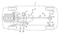
- FIG. 1is a schematic diagram of an exemplary powertrain in a motor vehicle
- FIG. 2is a schematic diagram of a portion of an exemplary hydraulic control system.
- a motor vehicleis shown and generally indicated by reference number 5 .
- the motor vehicle 5is illustrated as a passenger car, but it should be appreciated that the motor vehicle 5 may be any type of vehicle, such as a truck, van, etc.
- the motor vehicle 5includes an exemplary powertrain 10 . It should be appreciated at the outset that while a rear-wheel drive powertrain has been illustrated, the motor vehicle 5 may have a front-wheel drive powertrain without departing from the scope of the present invention.
- the powertrain 10generally includes an engine 12 interconnected with a transmission 14 .
- the engine 12may be a conventional internal combustion engine or an electric engine, or any other type of prime mover, without departing from the scope of the present disclosure.
- the engine 12supplies a driving torque to the transmission 14 through a flexplate 15 or other connecting device that is connected to a starting device 16 .
- the starter device 16may be a hydrodynamic device, such as a fluid coupling or torque converter, a wet dual clutch, or an electric motor. It should be appreciated that any starting device between the engine 12 and the transmission 14 may be employed.
- the transmission 14includes a typically cast, metal housing 18 which encloses and protects the various components of the transmission 14 .
- the housing 18includes a variety of apertures, passageways, shoulders and flanges which position and support these components.
- the transmission 14includes a transmission input shaft 20 and a transmission output shaft 22 . Disposed between the transmission input shaft 20 and the transmission output shaft 22 is a gear and clutch arrangement 24 .
- the transmission input shaft 20is functionally interconnected with the engine 12 via the starting device 16 and receives input torque or power from the engine 12 .
- the transmission input shaft 20may be a turbine shaft in the case where the starting device 16 is a hydrodynamic device, dual input shafts where the starting device 16 is dual clutch, or a drive shaft where the starting device 16 is an electric motor.
- the transmission output shaft 22is preferably connected with a final drive unit 26 which includes, for example, propshaft 28 , differential assembly 30 , and drive axles 32 connected to wheels 33 .
- the transmission input shaft 20is coupled to and provides drive torque to the gear and clutch arrangement 24 .
- the gear and clutch arrangement 24includes a plurality of gear sets, a plurality of clutches and/or brakes, and a plurality of shafts.
- the plurality of gear setsmay include individual intermeshing gears, such as planetary gear sets, that are connected to or selectively connectable to the plurality of shafts through the selective actuation of the plurality of clutches/brakes.
- the plurality of shaftsmay include layshafts or countershafts, sleeve and center shafts, reverse or idle shafts, or combinations thereof.
- the clutches/brakesare selectively engageable to initiate at least one of a plurality of gear or speed ratios by selectively coupling individual gears within the plurality of gear sets to the plurality of shafts. It should be appreciated that the specific arrangement and number of the gear sets, clutches/brakes 34 , and shafts within the transmission 14 may vary without departing from the scope of the present disclosure.
- the motor vehicle 5includes a control system 36 .
- the control system 36may include a transmission control module, an engine control module, or a hybrid control module, or any other type of controller.
- the control system 36may include one or more an electronic control devices having a preprogrammed digital computer or processor, control logic, memory used to store data, and at least one I/O peripheral.
- the control logicincludes a plurality of logic routines for monitoring, manipulating, and generating data.
- the control module 36controls the actuation of the clutches/brakes 34 via a hydraulic control system 38 .
- the hydraulic control system 38is operable to selectively engage the clutches/brakes 34 by selectively communicating a hydraulic fluid to the clutches/brakes 34 that engages the clutches/brakes 34 .
- the control module 36is also in communication with a plurality of sensors located throughout the motor vehicle 5 .
- the control module 36communicates with engine speed and temperature sensors 37 A and 37 B, a brake pedal position sensor 37 C, an ignition key sensor 37 D, a vehicle speed sensor 37 E, to name but a few.
- the hydraulic control system 38is operable to selectively engage the clutches/brakes 34 by selectively communicating a hydraulic fluid 44 from a sump 46 to a clutch actuation circuit 48 .
- the clutch actuation circuit 48includes clutch control solenoids, valves, and actuators operable to engage the plurality of clutches/brakes 34 .
- the hydraulic fluid 44is communicated to the clutch actuation circuit 48 under pressure from either an engine driven pump 50 or an accumulator 52 .
- the sump 46is a tank or reservoir to which the hydraulic fluid 44 returns and collects from various components and regions of the automatic transmission 14 .
- the hydraulic fluid 44is forced from the sump 46 and communicated throughout the hydraulic control system 38 via the pump 50 .
- the pump 50may be, for example, a gear pump, a vane pump, a gerotor pump, or any other positive displacement pump.
- the pump 50includes an inlet port 54 and an outlet port 56 .
- the inlet port 54communicates with the sump 46 via a suction line 58 .
- the outlet port 56communicates pressurized hydraulic fluid 44 to a main line pressure circuit 60 .
- the main line pressure circuit 60may include various optional features including, for example, a spring biased blow-off safety valve, a pressure side filter, or a spring biased check valve.
- the main line pressure circuit 60communicates with the clutch actuation circuit 48 and a solenoid 76 .
- the solenoid 76is in fluid communication with an accumulator supply line 77 .
- the solenoid 76is electrically controlled by the control module 36 and is operable to control the charge state of the accumulator 52 .
- the solenoid 76is preferably an on/off solenoid having a solenoid valve 76 A moveable between a first position and a second position. In the first position, the main line pressure circuit 60 is in fluid communication with a flow restricting orifice 76 B that limits the amount of hydraulic fluid 44 that can be bled off the main line pressure circuit 60 in order to prevent the clutch actuation circuit 48 from being starved of hydraulic fluid 44 .
- the flow restricting orifice 76 Bcommunicates with a one way check ball or poppet valve 76 C.
- the check ball valve 76 Cis configured to maintain pressure within the accumulator 52 .
- the solenoid valve 76 Ais energized and moved to the second position, the restriction orifice 76 B is positioned in parallel with a one way check or poppet valve 76 D.
- the check ball valve 76 Dprevents fluid backflow into the accumulator 52 .
- the solenoid 76communicates with the accumulator 52 and a pressure sensor 78 .
- the accumulator 52is an energy storage device in which the non-compressible hydraulic fluid 44 is held under pressure by an external source.
- the accumulator 52includes a piston that has a seal that slides along a bore of the accumulator housing. On one side of the piston there is hydraulic fluid 44 and on the other side of the piston there is one or more springs and air.
- the accumulator 52uses a combination of spring(s) and air to generate the force on one side of the piston that reacts against the hydraulic fluid pressure on the opposite side of the piston.
- An example of an accumulator for use with the present inventionis disclosed in commonly assigned U.S.
- the accumulator 52when charged, effectively replaces the pump 50 as the source of pressurized hydraulic fluid 44 , thereby eliminating the need for the pump 50 to run continuously.
- the pressure sensor 78reads the pressure of the hydraulic fluid 44 within the supply line 77 in real time and provides this data to the control module 36 .
- Other types of sensors, such as volume or position sensors,may also be included.
- the control of flow in out of the accumulator 52is performed through two different processes using the same solenoid 76 .
- hydraulic fluid 44flows from the main line pressure circuit 60 into the de-energized solenoid 76 .
- the hydraulic fluid 44unseats the check valve 76 C and flows into the accumulator 52 . Therefore, in order to charge the accumulator 52 , the pressure in the main line pressure circuit 60 must be higher than the pressure in the accumulator 52 in order to unseat the check valve 76 C.
- the hydraulic fluid 44 pressureacts on the piston, pushing it against the air and spring(s) on the other side.
- the pistonwill move allowing more oil to flow into the accumulator 52 . If the force generated by air and spring(s) is equal to the force generated by hydraulic fluid 44 pressure, then there will be no movement of the piston. If the force generated by the air and spring(s) is greater than the force generated by hydraulic fluid 44 , the piston will move causing the accumulator 52 to exhaust.
- the accumulator 52 pressureis monitored by the pressure sensor 78 to determine if the accumulator 52 is fully filled. The accumulator 52 can be filled quickly by opening or energizing the solenoid 76 , however this places a large flow demand on the main line pressure circuit 60 .
- Hydraulic fluid 44is stored in the accumulator 52 at a set volume and pressure while the engine 12 is off. While the solenoid 76 is off, hydraulic fluid 44 will remain in the accumulator 52 as there is no path for any hydraulic fluid 44 to bypass the solenoid 76 , excluding the minute amount of leakage that weeps past the clearances in the parts of the solenoid valve 76 A. When the solenoid 76 is energized electrically, it opens. The decision to energize the solenoid 76 is determined based on an engine start command in order to have the clutches/brakes 34 ready for vehicle launch.
- Energizing the solenoid 76allows hydraulic fluid 44 to leave the accumulator 52 , enter the solenoid 76 , and flow into the main line pressure circuit 60 that feeds the clutch actuation circuit 48 .
- the clutch actuation circuit 48controls the pressure and flow rate to the clutches/brakes 34 to control clutch capacity during the engine start up event to eliminate torque bumps and increase the isolation of engine start up vibrations.
- the accumulator 52 charge processcan start over again to allow for another engine off event.
- the automatic stopwill be prohibited: the pressure in the accumulator 52 is not high enough or the hydraulic fluid 44 temperature is low.
- the pressure in the main line pressure circuit 60is increased to charge the accumulator 52 at proper conditions.
- the hydraulic fluid 44 temperatureincreases beyond a threshold for allowing automatic stop, the accumulator 52 is discharged to discharge the cold fluid in the accumulator 52 in order to exchange the cold fluid in the accumulator 52 with the warmer fluid before allowing automatic stop.
- the controller 36will restart the engine 12 and finish the automatic stop start. After key off and vehicle stop, the accumulator 52 is discharged.
Landscapes
- Engineering & Computer Science (AREA)
- Chemical & Material Sciences (AREA)
- Combustion & Propulsion (AREA)
- Mechanical Engineering (AREA)
- Transportation (AREA)
- Automation & Control Theory (AREA)
- General Engineering & Computer Science (AREA)
- Control Of Transmission Device (AREA)
Abstract
Description
Claims (13)
Priority Applications (5)
| Application Number | Priority Date | Filing Date | Title |
|---|---|---|---|
| US13/288,666US8639424B2 (en) | 2011-11-03 | 2011-11-03 | System and method for controlling an automatic engine stop-start accumulator |
| DE102012219832.6ADE102012219832B4 (en) | 2011-11-03 | 2012-10-30 | SYSTEM AND METHOD FOR CONTROLLING A PRESSURE ACCUMULATOR FOR AUTOMATIC ENGINE STOP-START |
| KR1020120122927AKR20130049158A (en) | 2011-11-03 | 2012-11-01 | System and method for controlling an automatic engine stop-start accumulator |
| CN201210432517.9ACN103085806B (en) | 2011-11-03 | 2012-11-02 | For controlling the system and method for automatic engine stop-start accumulator |
| KR1020140069169AKR20140080474A (en) | 2011-11-03 | 2014-06-09 | System and method for controlling an automatic engine stop-start accumulator |
Applications Claiming Priority (1)
| Application Number | Priority Date | Filing Date | Title |
|---|---|---|---|
| US13/288,666US8639424B2 (en) | 2011-11-03 | 2011-11-03 | System and method for controlling an automatic engine stop-start accumulator |
Publications (2)
| Publication Number | Publication Date |
|---|---|
| US20130116898A1 US20130116898A1 (en) | 2013-05-09 |
| US8639424B2true US8639424B2 (en) | 2014-01-28 |
Family
ID=48129113
Family Applications (1)
| Application Number | Title | Priority Date | Filing Date |
|---|---|---|---|
| US13/288,666Active2031-12-14US8639424B2 (en) | 2011-11-03 | 2011-11-03 | System and method for controlling an automatic engine stop-start accumulator |
Country Status (4)
| Country | Link |
|---|---|
| US (1) | US8639424B2 (en) |
| KR (2) | KR20130049158A (en) |
| CN (1) | CN103085806B (en) |
| DE (1) | DE102012219832B4 (en) |
Cited By (9)
| Publication number | Priority date | Publication date | Assignee | Title |
|---|---|---|---|---|
| US20130178328A1 (en)* | 2012-01-11 | 2013-07-11 | Developpement Effenco Inc. | Fuel saving system that facilitates vehicle re-starts with the engine off |
| US20130263584A1 (en)* | 2012-04-09 | 2013-10-10 | GM Global Technology Operations LLC | System and method for accumulator fluid mixing |
| US20140046553A1 (en)* | 2012-08-09 | 2014-02-13 | GM Global Technology Operations LLC | System and method for controlling an accumulator based on vehicle conditions |
| US8734293B1 (en)* | 2012-12-06 | 2014-05-27 | Ford Global Technologies, Llc | Accumulator for maintaining hydraulic pressure following an engine restart |
| US20140163845A1 (en)* | 2012-12-12 | 2014-06-12 | GM Global Technology Operations LLC | Hydraulic accumulator fill estimation for controlling automatic engine stop/start |
| US10619726B2 (en) | 2015-08-20 | 2020-04-14 | Zf Friedrichshafen Ag | Hydraulic system of an automatic gearbox |
| US10704676B2 (en) | 2018-07-30 | 2020-07-07 | Ford Global Technologies, Llc | System and method of charging a transmission accumulator |
| US10703356B2 (en) | 2016-02-16 | 2020-07-07 | Développement Effenco Inc. | Expanded functionality stop-start fuel saving system for vocational vehicles |
| US11639594B2 (en) | 2021-01-14 | 2023-05-02 | Deere & Company | Transmission system with traction motor-driven hydraulic circuit and method of controlling same |
Families Citing this family (8)
| Publication number | Priority date | Publication date | Assignee | Title |
|---|---|---|---|---|
| US9139189B2 (en)* | 2012-08-20 | 2015-09-22 | GM Global Technology Operations LLC | Scalable hydraulic charging in a vehicle having engine autostop/start functionality |
| US9090241B2 (en)* | 2012-09-24 | 2015-07-28 | Gm Global Technology Operations, Llc | System and method for controlling an automatic stop-start |
| US9308909B2 (en)* | 2013-06-06 | 2016-04-12 | Ford Global Technologies, Llc | Method and system for engine control |
| WO2015175262A1 (en)* | 2014-05-16 | 2015-11-19 | Borgwarner Inc. | Clutch control with integral accumulator discharge control |
| US9829090B2 (en)* | 2014-12-23 | 2017-11-28 | GM Global Technology Operations LLC | Transmission fluid control systems and methods for engine auto-stops |
| DE102016203845A1 (en)* | 2016-03-09 | 2017-09-14 | Bayerische Motoren Werke Aktiengesellschaft | Start-stop device for initiating an automatic shutdown of a prime mover |
| US10322725B2 (en)* | 2016-07-14 | 2019-06-18 | Ford Global Technologies, Llc | Powertrain lash management |
| CN107132859B (en)* | 2017-03-24 | 2023-04-04 | 中国第一汽车股份有限公司 | Drive train torsional vibration control method for carrying wet type double-clutch transmission |
Citations (21)
| Publication number | Priority date | Publication date | Assignee | Title |
|---|---|---|---|---|
| US4955256A (en)* | 1988-09-22 | 1990-09-11 | Toyota Jidosha Kabushiki Kaisha | Transmission control apparatus, having means for determining the completion of a shifting action of a coupling device with pressure adjusting accumulator |
| US4975845A (en)* | 1988-04-29 | 1990-12-04 | Chrysler Corporation | Method of operating an electronic automatic transmission system |
| US5193060A (en)* | 1989-05-12 | 1993-03-09 | Chrysler Corp | Method of hold-speed control during an upshift |
| US5251512A (en)* | 1991-10-15 | 1993-10-12 | General Motors Corporation | Dynamic shift control for an automatic transmission |
| US6074320A (en) | 1997-10-02 | 2000-06-13 | Nsk Ltd. | Continuously variable transmission |
| US6470252B2 (en)* | 2000-06-22 | 2002-10-22 | Denso Corporation | Integrated vehicle control system having manager ECU |
| US20030109970A1 (en)* | 2001-12-07 | 2003-06-12 | Aisin Aw Co., Ltd. | Driving control device of vehicle |
| US6799109B2 (en)* | 2002-02-18 | 2004-09-28 | Aisin Aw Co., Ltd. | Vehicle control apparatus |
| US7280907B2 (en)* | 2006-02-22 | 2007-10-09 | Detroit Diesel Corporation | Method of enhancing accelerator pedal safety interlock feature |
| US20080020896A1 (en)* | 2006-07-20 | 2008-01-24 | Toyota Jidosha Kabushiki Kaisha | Control apparatus for vehicular automatic transmission and method of controlling vehicular automatic transmission |
| US7440833B2 (en)* | 2006-01-24 | 2008-10-21 | Chrysler Llc | Clutch fill volume learning strategy for transmission control |
| US20090112431A1 (en)* | 2006-07-05 | 2009-04-30 | Per-Olof Davidsson | Hydraulic System For An All-Wheel Drive System And Method Of Controlling Said Hydraulic System |
| US7556120B2 (en)* | 2006-05-25 | 2009-07-07 | Gm Global Technology Operations, Inc. | Method and apparatus to control hydraulic pressure in an electro-mechanical transmission |
| US20090241883A1 (en)* | 2008-03-28 | 2009-10-01 | Mazda Motor Coporation | Control method for internal combustion engine system, and internal combustion engine system |
| US20090299586A1 (en)* | 2008-05-27 | 2009-12-03 | Gm Global Technology Operations, Inc. | Method to autostart an internal combustion engine in a hybrid powertrain system |
| US20100282020A1 (en) | 2007-09-04 | 2010-11-11 | Christopher John Greenwood | Continuously variable transmission |
| US20110139285A1 (en) | 2009-12-10 | 2011-06-16 | Gm Global Technology Operations, Inc. | Combination spring and gas filled accumulator |
| US7970505B2 (en)* | 2007-03-22 | 2011-06-28 | Toyota Jidosha Kabushiki Kaisha | Control apparatus for hybrid vehicle drive system |
| US20120088630A1 (en) | 2010-10-08 | 2012-04-12 | GM Global Technology Operations LLC | System and method for controlling an automatic engine stop-start |
| US20120088631A1 (en) | 2010-10-11 | 2012-04-12 | GM Global Technology Operations LLC | System and method for controlling an automatic engine stop-start based on transmission conditions |
| US20120088632A1 (en) | 2010-10-12 | 2012-04-12 | GM Global Technology Operations LLC | System and method for controlling an automatic engine restart |
Family Cites Families (2)
| Publication number | Priority date | Publication date | Assignee | Title |
|---|---|---|---|---|
| JP3807145B2 (en) | 1999-04-30 | 2006-08-09 | トヨタ自動車株式会社 | Control device for vehicle engine restart |
| DE10211461C1 (en) | 2002-03-15 | 2003-07-31 | Daimler Chrysler Ag | Automatic stop-start method for automobile IC engine blocks stopping of engine when air-conditioning is required |
- 2011
- 2011-11-03USUS13/288,666patent/US8639424B2/enactiveActive
- 2012
- 2012-10-30DEDE102012219832.6Apatent/DE102012219832B4/enactiveActive
- 2012-11-01KRKR1020120122927Apatent/KR20130049158A/ennot_activeCeased
- 2012-11-02CNCN201210432517.9Apatent/CN103085806B/enactiveActive
- 2014
- 2014-06-09KRKR1020140069169Apatent/KR20140080474A/ennot_activeWithdrawn
Patent Citations (22)
| Publication number | Priority date | Publication date | Assignee | Title |
|---|---|---|---|---|
| US4975845A (en)* | 1988-04-29 | 1990-12-04 | Chrysler Corporation | Method of operating an electronic automatic transmission system |
| US4955256A (en)* | 1988-09-22 | 1990-09-11 | Toyota Jidosha Kabushiki Kaisha | Transmission control apparatus, having means for determining the completion of a shifting action of a coupling device with pressure adjusting accumulator |
| US5193060A (en)* | 1989-05-12 | 1993-03-09 | Chrysler Corp | Method of hold-speed control during an upshift |
| US5251512A (en)* | 1991-10-15 | 1993-10-12 | General Motors Corporation | Dynamic shift control for an automatic transmission |
| US6074320A (en) | 1997-10-02 | 2000-06-13 | Nsk Ltd. | Continuously variable transmission |
| US6470252B2 (en)* | 2000-06-22 | 2002-10-22 | Denso Corporation | Integrated vehicle control system having manager ECU |
| US20030109970A1 (en)* | 2001-12-07 | 2003-06-12 | Aisin Aw Co., Ltd. | Driving control device of vehicle |
| US6647326B2 (en)* | 2001-12-07 | 2003-11-11 | Aisin Aw Co., Ltd. | Driving control device of vehicle |
| US6799109B2 (en)* | 2002-02-18 | 2004-09-28 | Aisin Aw Co., Ltd. | Vehicle control apparatus |
| US7440833B2 (en)* | 2006-01-24 | 2008-10-21 | Chrysler Llc | Clutch fill volume learning strategy for transmission control |
| US7280907B2 (en)* | 2006-02-22 | 2007-10-09 | Detroit Diesel Corporation | Method of enhancing accelerator pedal safety interlock feature |
| US7556120B2 (en)* | 2006-05-25 | 2009-07-07 | Gm Global Technology Operations, Inc. | Method and apparatus to control hydraulic pressure in an electro-mechanical transmission |
| US20090112431A1 (en)* | 2006-07-05 | 2009-04-30 | Per-Olof Davidsson | Hydraulic System For An All-Wheel Drive System And Method Of Controlling Said Hydraulic System |
| US20080020896A1 (en)* | 2006-07-20 | 2008-01-24 | Toyota Jidosha Kabushiki Kaisha | Control apparatus for vehicular automatic transmission and method of controlling vehicular automatic transmission |
| US7970505B2 (en)* | 2007-03-22 | 2011-06-28 | Toyota Jidosha Kabushiki Kaisha | Control apparatus for hybrid vehicle drive system |
| US20100282020A1 (en) | 2007-09-04 | 2010-11-11 | Christopher John Greenwood | Continuously variable transmission |
| US20090241883A1 (en)* | 2008-03-28 | 2009-10-01 | Mazda Motor Coporation | Control method for internal combustion engine system, and internal combustion engine system |
| US20090299586A1 (en)* | 2008-05-27 | 2009-12-03 | Gm Global Technology Operations, Inc. | Method to autostart an internal combustion engine in a hybrid powertrain system |
| US20110139285A1 (en) | 2009-12-10 | 2011-06-16 | Gm Global Technology Operations, Inc. | Combination spring and gas filled accumulator |
| US20120088630A1 (en) | 2010-10-08 | 2012-04-12 | GM Global Technology Operations LLC | System and method for controlling an automatic engine stop-start |
| US20120088631A1 (en) | 2010-10-11 | 2012-04-12 | GM Global Technology Operations LLC | System and method for controlling an automatic engine stop-start based on transmission conditions |
| US20120088632A1 (en) | 2010-10-12 | 2012-04-12 | GM Global Technology Operations LLC | System and method for controlling an automatic engine restart |
Cited By (13)
| Publication number | Priority date | Publication date | Assignee | Title |
|---|---|---|---|---|
| US20130178328A1 (en)* | 2012-01-11 | 2013-07-11 | Developpement Effenco Inc. | Fuel saving system that facilitates vehicle re-starts with the engine off |
| US9132824B2 (en) | 2012-01-11 | 2015-09-15 | Développement Effenco Inc. | Fuel saving system that facilitates vehicle re-starts with the engine off |
| US8840524B2 (en)* | 2012-01-11 | 2014-09-23 | Développement Effenco Inc. | Fuel saving system that facilitates vehicle re-starts with the engine off |
| US9052014B2 (en)* | 2012-04-09 | 2015-06-09 | Gm Global Technology Operations, Llc | System and method for accumulator fluid mixing |
| US20130263584A1 (en)* | 2012-04-09 | 2013-10-10 | GM Global Technology Operations LLC | System and method for accumulator fluid mixing |
| US20140046553A1 (en)* | 2012-08-09 | 2014-02-13 | GM Global Technology Operations LLC | System and method for controlling an accumulator based on vehicle conditions |
| US8855878B2 (en)* | 2012-08-09 | 2014-10-07 | Gm Global Technology Operations, Llc. | System and method for controlling an accumulator based on vehicle conditions |
| US8734293B1 (en)* | 2012-12-06 | 2014-05-27 | Ford Global Technologies, Llc | Accumulator for maintaining hydraulic pressure following an engine restart |
| US20140163845A1 (en)* | 2012-12-12 | 2014-06-12 | GM Global Technology Operations LLC | Hydraulic accumulator fill estimation for controlling automatic engine stop/start |
| US10619726B2 (en) | 2015-08-20 | 2020-04-14 | Zf Friedrichshafen Ag | Hydraulic system of an automatic gearbox |
| US10703356B2 (en) | 2016-02-16 | 2020-07-07 | Développement Effenco Inc. | Expanded functionality stop-start fuel saving system for vocational vehicles |
| US10704676B2 (en) | 2018-07-30 | 2020-07-07 | Ford Global Technologies, Llc | System and method of charging a transmission accumulator |
| US11639594B2 (en) | 2021-01-14 | 2023-05-02 | Deere & Company | Transmission system with traction motor-driven hydraulic circuit and method of controlling same |
Also Published As
| Publication number | Publication date |
|---|---|
| DE102012219832A1 (en) | 2013-05-08 |
| US20130116898A1 (en) | 2013-05-09 |
| CN103085806A (en) | 2013-05-08 |
| CN103085806B (en) | 2016-08-24 |
| KR20140080474A (en) | 2014-06-30 |
| DE102012219832B4 (en) | 2022-10-27 |
| KR20130049158A (en) | 2013-05-13 |
Similar Documents
| Publication | Publication Date | Title |
|---|---|---|
| US8639424B2 (en) | System and method for controlling an automatic engine stop-start accumulator | |
| US8702562B2 (en) | System and method for controlling an automatic engine stop-start based on transmission conditions | |
| US8591381B2 (en) | System and method for controlling an automatic engine restart | |
| US8585548B2 (en) | System and method for controlling an automatic engine stop-start | |
| US9052014B2 (en) | System and method for accumulator fluid mixing | |
| US8855878B2 (en) | System and method for controlling an accumulator based on vehicle conditions | |
| US8375710B2 (en) | Transmission hydraulic control system having an accumulator for priming a pump | |
| US9163720B2 (en) | Transmission hydraulic control system having an automatic engine stop-start accumulator | |
| US9856959B2 (en) | Latching clutch control system | |
| US20190136970A1 (en) | Transmission device | |
| US8771121B2 (en) | Latching clutch valve control system | |
| US8795119B2 (en) | Latching clutch valve control system | |
| US9090241B2 (en) | System and method for controlling an automatic stop-start | |
| JP2018054074A (en) | Change gear | |
| EP3092426B1 (en) | System for adjusting fluid volume in a transmission and method thereof | |
| US10704677B2 (en) | Method of discharging transmission accumulator | |
| US10704615B2 (en) | Vehicle and system for controlling a vehicle transmission |
Legal Events
| Date | Code | Title | Description |
|---|---|---|---|
| AS | Assignment | Owner name:GM GLOBAL TECHNOLOGY OPERATIONS LLC, MICHIGAN Free format text:ASSIGNMENT OF ASSIGNORS INTEREST;ASSIGNORS:LUNDBERG, PHILIP C.;MARIN, CARLOS E.;BOCKENSTETTE, CASIE M.;AND OTHERS;SIGNING DATES FROM 20111102 TO 20111103;REEL/FRAME:027175/0146 | |
| AS | Assignment | Owner name:WILMINGTON TRUST COMPANY, DELAWARE Free format text:SECURITY AGREEMENT;ASSIGNOR:GM GLOBAL TECHNOLOGY OPERATIONS LLC;REEL/FRAME:028458/0184 Effective date:20101027 | |
| FEPP | Fee payment procedure | Free format text:PAYOR NUMBER ASSIGNED (ORIGINAL EVENT CODE: ASPN); ENTITY STATUS OF PATENT OWNER: LARGE ENTITY | |
| STCF | Information on status: patent grant | Free format text:PATENTED CASE | |
| AS | Assignment | Owner name:GM GLOBAL TECHNOLOGY OPERATIONS LLC, MICHIGAN Free format text:RELEASE BY SECURED PARTY;ASSIGNOR:WILMINGTON TRUST COMPANY;REEL/FRAME:034186/0776 Effective date:20141017 | |
| FPAY | Fee payment | Year of fee payment:4 | |
| MAFP | Maintenance fee payment | Free format text:PAYMENT OF MAINTENANCE FEE, 8TH YEAR, LARGE ENTITY (ORIGINAL EVENT CODE: M1552); ENTITY STATUS OF PATENT OWNER: LARGE ENTITY Year of fee payment:8 | |
| MAFP | Maintenance fee payment | Free format text:PAYMENT OF MAINTENANCE FEE, 12TH YEAR, LARGE ENTITY (ORIGINAL EVENT CODE: M1553); ENTITY STATUS OF PATENT OWNER: LARGE ENTITY Year of fee payment:12 |