US8638498B2 - Eyebox adjustment for interpupillary distance - Google Patents
Eyebox adjustment for interpupillary distanceDownload PDFInfo
- Publication number
- US8638498B2 US8638498B2US13/343,675US201213343675AUS8638498B2US 8638498 B2US8638498 B2US 8638498B2US 201213343675 AUS201213343675 AUS 201213343675AUS 8638498 B2US8638498 B2US 8638498B2
- Authority
- US
- United States
- Prior art keywords
- light
- image
- distance
- optical lens
- eyeboxes
- Prior art date
- Legal status (The legal status is an assumption and is not a legal conclusion. Google has not performed a legal analysis and makes no representation as to the accuracy of the status listed.)
- Active, expires
Links
Images


Classifications
- G—PHYSICS
- G02—OPTICS
- G02B—OPTICAL ELEMENTS, SYSTEMS OR APPARATUS
- G02B30/00—Optical systems or apparatus for producing three-dimensional [3D] effects, e.g. stereoscopic images
- G02B30/20—Optical systems or apparatus for producing three-dimensional [3D] effects, e.g. stereoscopic images by providing first and second parallax images to an observer's left and right eyes
- G02B30/34—Stereoscopes providing a stereoscopic pair of separated images corresponding to parallactically displaced views of the same object, e.g. 3D slide viewers
- G02B30/36—Stereoscopes providing a stereoscopic pair of separated images corresponding to parallactically displaced views of the same object, e.g. 3D slide viewers using refractive optical elements, e.g. prisms, in the optical path between the images and the observer
- G—PHYSICS
- G02—OPTICS
- G02B—OPTICAL ELEMENTS, SYSTEMS OR APPARATUS
- G02B7/00—Mountings, adjusting means, or light-tight connections, for optical elements
- G02B7/02—Mountings, adjusting means, or light-tight connections, for optical elements for lenses
- G02B7/12—Adjusting pupillary distance of binocular pairs
Definitions
- Virtual realitycan be viewed as a computer-generated simulated environment in which a user has an apparent physical presence.
- a virtual reality experiencecan be generated in 3D and viewed with a head-mounted display (HMD), such as glasses or other wearable display device that has near-eye display panels as lenses to display a virtual reality environment, which replaces the actual environment.
- HMDhead-mounted display
- Augmented realityprovides that a user can still see through the display lenses of the glasses or other wearable display device to view the surrounding environment, yet also see images of virtual objects that are generated for display and appear as a part of the environment.
- Augmented realitycan include any type of input such as audio and haptic inputs, as well as virtual images, graphics, and video that enhances or augments the environment that a user experiences.
- there are many challenges and design constraints with augmented realityfrom generation of the virtual objects and images so that they appear realistic in a real environment, to developing the optics small and precise enough for implementation with a wearable display device.
- a challenge to the implementation of wearable display devices, such as a head-mounted display (HMD), for virtual and/or augmented realityis that one size does not fit all users. Just as typical users come in all shapes and sizes, so is the interpupillary distance between different users' pupils of their eyes. Additionally, the distance from a user's nose to the pupil of one eye may be different than the distance from the user's nose to the pupil of the other eye.
- the right and left display lens systemshave a small lateral margin to approximately center a user's eyes on the optical axis of the display lens systems.
- This small lateral margin of adjustment for varying interpupillary distancesis commonly referred to as the eyebox for a display lens system, and the eyebox represents the range within which a user's eye should be positioned for viewing with a wearable display device.
- Some conventional systemsattempt to compensate for the uniqueness of different users with a mechanical adjustment system, which is then a wearable display device that fits only one person.
- Another compensation techniqueis to oversize the eyebox for a general, one-size-fits all approach. However, this is largely cost-prohibitive due to the expensive optical systems in wearable display devices. Additionally, the one-size-fits all approach to oversize the eyebox results in a very large and heavy optical system, which is also impractical for consumer head-mounted display systems.
- a first optical lensreceives light of an image from a display optic at a projected orientation of the light, and the first optical lens can deviate the light of the image by a deviation angle from the projected orientation of the light.
- a second optical lensreceives the light of the image from the first optical lens at the deviation angle, and the second optical lens alters the deviated light of the image back to the projected orientation of the light for viewing the image.
- Left and right eyeboxesalign with respective left and right eyes that view the image, and a distance between the left and right eyeboxes approximately correlates to an interpupillary distance between the left and right eyes.
- the light of the imagecan be laterally shifted to increase or decrease the distance between the left and right eyeboxes.
- the light of the imageis laterally shifted based on the deviation angle and a distance between the first optical lens and the second optical lens.
- Designated position settings of the left and right eyeboxescan be implemented for viewing the image. In a first position, the distance between the left and right eyeboxes is increased to correlate to a wide interpupillary distance between the left and right eyes. In a second position, the distance between the left and right eyeboxes is not laterally shifted when the first optical lens projects the light of the image through at the projected orientation of the light. In a third position, the distance between the left and right eyeboxes is decreased to correlate to a narrow interpupillary distance between the left and right eyes.
- the first optical lenscan be implemented for on-off control, where the first and third positions are enabled when the first optical lens is turned-on, and the second position is enabled when the first optical lens is turned-off.
- the first optical lenscan be implemented for variable control of the position settings to vary the distance between the left and right eyeboxes to correlate with the interpupillary distance between the left and right eyes.
- an eye-tracking camerais implemented to image a location of the left and right eyes, and the distance between the left and right eyeboxes is adjusted based on the location of the left and right eyes.
- the distance between the left and right eyeboxesis based on a user input of the interpupillary distance between the left and right eyes.
- FIG. 1illustrates an example system in which embodiments of eyebox adjustment for interpupillary distance can be implemented.
- FIG. 2illustrates another example system in which embodiments of eyebox adjustment for interpupillary distance can be implemented.
- FIG. 3illustrates an example system that includes an example of a wearable display device in which embodiments of eyebox adjustment for interpupillary distance can be implemented.
- FIG. 4illustrates example method(s) of eyebox adjustment for interpupillary distance in accordance with one or more embodiments.
- FIG. 5illustrates example method(s) of eyebox adjustment for interpupillary distance in accordance with one or more embodiments.
- FIG. 6illustrates various components of an example device that can implement embodiments of eyebox adjustment for interpupillary distance.
- Embodiments of eyebox adjustment for interpupillary distanceare described.
- a challenge to the implementation of wearable display devices, such as a head-mounted display (HMD), for virtual and/or augmented realityis that one size does not fit all users due to the interpupillary distance between different users' pupils of their eyes.
- the right and left display lens systemshave an eyebox that is the range within which a user's eye should be positioned for viewing with a wearable display device.
- Embodiments of eyebox adjustment for interpupillary distanceprovides that the eyeboxes for the display lens systems of a wearable display device can be laterally adjusted to accommodate different users.
- a wearable display devicecan be implemented for designated position settings of the left and right eyeboxes, such as a first position that correlates to a wide interpupillary distance between the left and right eyes, a second position that correlates to a mid-interpupillary distance between the left and right eyes, and a third position that correlates to a narrow interpupillary distance between the left and right eyes.
- a wearable display devicecan be implemented for variable control of position settings to vary the distance between the left and right eyeboxes to correlate with the interpupillary distance between the left and right eyes of a user.
- eyebox adjustment for interpupillary distancecan be implemented in any number of different devices, systems, environments, and/or configurations, embodiments of eyebox adjustment for interpupillary distance are described in the context of the following example devices, systems, and methods.
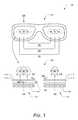
- FIG. 1illustrates an example system 100 in which various embodiments of eyebox adjustment for interpupillary distance can be implemented.
- An example wearable display device 102includes left and right imaging systems, such as imaging systems 104 that are viewed from a perspective 106 of the wearable display device, as if viewing the imaging systems from the top of the device.
- the imaging systems 104can be implemented as left and right display lens systems of the wearable display device described with reference to FIG. 3 .
- a wearable display devicecan be implemented as any type of glasses or head-mounted display (HMD) that includes implementations of the imaging systems 104 (e.g., left and right display lens systems) through which a user can view the surrounding environment, yet also see virtual images that are generated for display and appear as a part of the environment.
- the wearable display device and/or a controller unitimplements an imaging application, such as a software application, to implement embodiments of eyebox adjustment for interpupillary distance as described herein.
- the imaging systems 104include a display optic 108 , such as a see-through and reflecting waveguide, through which light of an image (e.g., an image of the environment as viewed through the wearable display device) is projected to a first optical lens 110 and through to a second optical lens 112 .
- a display optic 108such as a see-through and reflecting waveguide
- the light 116is projected at a particular orientation through the waveguide optic 108 and through the optical lenses to a left eyebox 118 that approximately correlates to a position of a user's left eye.
- This example of the left imaging system 114can be implemented for both the left and right imaging systems, and the projected orientation of the light approximately straight through the left and right imaging systems correlates to a mid-interpupillary distance 120 between the left and right eyes.
- the left and right eyeboxesare not laterally shifted when the first optical lens 110 projects the light of an image through at the projected orientation of the light.
- the left and right imaging systemsmay be described from the perspective of looking at the wearable display device.
- the light 124 of the imageis projected at a particular orientation through the waveguide optic 108 to the first optical lens 110 .
- the projected orientation of the light in this exampleis approximately perpendicular to the waveguide optic.
- the first optical lensreceives the light at the projected orientation and is implemented to then deviate the light of the image by a deviation angle 126 (theta) from the projected orientation of the light.
- the second optical lens 112then receives the light of the image as projected from the first optical lens at the deviation angle, and the second optical lens is implemented to alter the deviated light back to the projected orientation for viewing the image.
- the light of the imageis shown deviated in two directions, and the light of the image is laterally shifted based on the deviation angle 126 (theta) and a distance 128 between the first optical lens 110 and the second optical lens 112 .
- the amount of lateral shiftcan be determined or controlled by an equation d ⁇ tan ⁇ theta.
- the lateral shift of the light to the left and/or rightwould be approximately 3.2 mm for an angle theta of 15° and a distance of 12 mm between the first and second optical lenses.
- This example of the right imaging system 122can be implemented for both the left and right imaging systems of the wearable display device 102 .
- the projected orientation of the light 124can be laterally shifted to direct the light at a right eyebox 130 , shown laterally shifted both outward and inward from a middle position of the eyebox to approximately correlate to different positions of the user's right eye.
- the projected orientation of the light 124can be laterally shifted through the imaging systems to correlate to a wide interpupillary distance 132 between the left and right eyes.
- the projected orientation of the lightcan be laterally shifted through the imaging systems to correlate to a narrow interpupillary distance 134 between the left and right eyes.
- the light of the imageis laterally shifted to increase or decrease the distance between the left and right eyeboxes, and the distance between the left eyebox 118 and the right eyebox 130 approximately correlates to an interpupillary distance between the left and right eyes.
- the first and second optical lenses 110 and 112 of the imaging systems 104can be implemented with transparent liquid crystal (LC) lenses.
- the first optical lens 110can be implemented for designated position settings, such as the wide, mid, and narrow distances between the left and right eyes.
- the designated position settingsmay also be termed large, medium, and small position settings, or by other designations.
- the first optical lens 110 of the imaging systemscan be implemented with an LC Fresnel lens that is configured for on-off control, where the mid-interpupillary distance 120 is enabled when the optical lens is turned-off, and the wide and narrow interpupillary distances 132 and 134 are enabled when the optical lens is turned-on.
- the first and/or second optical lenses 110 and 112 of the imaging systems 104can be implemented for variable adjustment (i.e., more than just the three settings).
- an active prism technologymay be utilized, such as switchable Bragg gratings (SBG), which can be implemented as very thin, active optical elements with switchable prisms.
- SBG active optical elementscan be implemented as binary (on/off), or for continuously variable adjustment.
- the line of sight between the first and second optical lenses 110 and 112can be shifted with prism optical elements that laterally shift to vary the degree of the deviation angle 126 between the first and second optical lenses to offset the line of sight to correlate with the interpupillary distance between the left and right eyes. An example of this system is shown and described with reference to FIG. 2 .
- the first optical lens 110 of the imaging systems 104can be implemented for variable, adjusted position settings of the distance between the left and right eyeboxes to correlate with the interpupillary distance between the left and right eyes.
- the imaging systems 104can each include an eye tracking camera 136 that images a location of the left and right eyes, and then the distance between the left and right eyeboxes is automatically adjusted based on the location of the left and right eyes.
- the distance between the left and right eyeboxescan be based on a user input of the interpupillary distance between the left and right eyes.
- FIG. 2illustrates another example system 200 in which various embodiments of eyebox adjustment for interpupillary distance can be implemented.
- the example systemincludes imaging systems 202 that can be implemented as left and right display lens systems of the wearable display device described with reference to FIG. 3 . Similar to the imaging systems described with reference to FIG. 1 , the imaging systems 202 include a display optic 108 , such as a see-through and reflecting waveguide, through which light of an image is projected to a first prism optical element 204 and through to a second prism optical element 206 .
- a display optic 108such as a see-through and reflecting waveguide
- the light 208is projected at a particular orientation through the waveguide optic 108 and through the prism optical elements to an eyebox 210 that approximately correlates to a position of a user's eye (e.g., the user's left and right eyes).
- the projected orientation of the light approximately straight through the left and right imaging systemscorrelates to an interpupillary distance 214 between the left and right eyes.
- the prism optical elements 204 and 206are offset in a direction 218 along the line of sight (e.g., relative to the configuration in the example shown at 212 ).
- the second prism optical element 206has been moved in the direction 218 to increase the spacing between the prism optical elements.
- the first prism optical element 204may be moved relative to the second prism optical element 206 and/or both of the prism optical elements may be moved perpendicular to the line of sight.
- the second prism optical element 206may be laterally shifted relative to the first prism optical element 204 .
- first prism optical element 204may be laterally shifted relative to the second prism optical element 206 and/or both of the prism optical elements may be laterally shifted.
- the initial projected orientation of the light 208 in this exampleis approximately perpendicular to the waveguide optic 108 .
- the first prism optical element 204receives the light at the projected orientation and then deviates the light of the image by a deviation angle (theta) from the projected orientation of the light.
- the second prism optical element 206then receives the light of the image as projected from the first prism optical element at the deviation angle, and the second prism optical element alters the deviated light back to the projected orientation for viewing the image.
- the altered orientation of the light through the left and right imaging systemscorrelates to an interpupillary distance 220 between the left and right eyes (which is wider than the interpupillary distance 214 ).
- the prism optical elements 204 and 206are further offset in the direction 218 , relative to the configuration in the example shown at 216 .
- the initial projected orientation of the light 208 in this exampleis approximately perpendicular to the waveguide optic 108 .
- the first prism optical element 204receives the light at the projected orientation and then deviates the light of the image by a larger deviation angle (theta) from the projected orientation of the light.
- the second prism optical element 206then receives the light of the image as projected from the first prism optical element at the larger deviation angle, and the second prism optical element alters the deviated light back to the projected orientation for viewing the image.
- the altered orientation of the light through the left and right imaging systemscorrelates to an interpupillary distance 224 between the left and right eyes (which is wider than the interpupillary distances 214 and 220 ).
- FIG. 3illustrates an example system 300 that includes an example wearable display device 302 in which embodiments of eyebox adjustment for interpupillary distance can be implemented.
- the wearable display devicecan be implemented as any type of glasses or head-mounted display (HMD) that includes display lens systems 304 (e.g., left and right display lens systems) through which a user can view the surrounding environment, yet also see virtual images (e.g., any type of object, video, text, graphic, and the like) that are generated for display and appear as a part of the environment.
- HMDhead-mounted display
- the wearable display device 302can be implemented as an independent, portable system that includes memory, software, a processor, and/or a power source. Alternatively or in addition, the wearable display device may be communicatively linked to a controller 306 that includes any one or combination of the memory, software, processor, and/or power source, such as a battery unit.
- the controllercan be implemented for wired or wireless communication with the wearable display device.
- the controller and/or the wearable display devicecan also be implemented with any number and combination of differing components as further described with reference to the example device shown in FIG. 6 .
- the controller and/or the wearable display deviceincludes an imaging application implemented as computer-executable instructions, such as a software application, and executed by a processor to implement embodiments of eyebox adjustment for interpupillary distance as described herein.
- the controllermay be implemented as a dedicated device (e.g., the wired controller 306 ), as a mobile phone 308 , a tablet or other portable computer device, a gaming system 310 , or as any other type of electronic device that can be implemented to process and generate virtual images for display as part of the environment that is viewed through the display lens system of the wearable display device.
- the controllermay communicate with the wearable display device wirelessly via WiFiTM, BluetoothTM, infrared (IR), RFID transmission, wireless Universal Serial Bus (WUSB), cellular, or via other wireless communication techniques.
- the example system 300also includes a data server 312 , or data service, that communicates, or otherwise distributes, virtual image data 314 to the wearable display device 302 via a communication network 316 .
- the data servermay be part of a network-based gaming system that generates virtual images for augmented reality display at the wearable display device.
- the data servermay be part of a navigation system that communicates navigation directions and information for display in the display lens systems 304 of the wearable display device.
- the data servermay be part of a messaging service, such as an e-mail or text messaging system, that communicates e-mail and/or text messages to the wearable display device for display in the display lens systems, where a user can read a message as an augmented reality image that is displayed over the environment viewed through the wearable display device.
- a messaging servicesuch as an e-mail or text messaging system
- the communication network 316can be implemented to include wired and/or wireless networks.
- the communication networkcan also be implemented using any type of network topology and/or communication protocol, and can be represented or otherwise implemented as a combination of two or more networks, to include IP-based networks and/or the Internet.
- the communication networkmay also include mobile operator networks that are managed by mobile operators, such as a communication service provider, cell-phone provider, and/or Internet service provider.
- the wearable display device 302includes a frame 318 , such as in the form of glasses, goggles, or any other structure, that supports and incorporates the various components of the device, as well as serves as a conduit for electrical and other component connections.
- a components module 320(or components modules on the left, right, and/or both sides of the device frame) incorporates any of the various components, such as processing and control circuitry, memory, software, a processor, GPS transceiver, and/or power source.
- the wearable display devicemay also include a microphone 322 to record audio data from the surrounding environment, as well as ear phones for audio feedback as part of an augmented reality experience.
- the wearable display device 302also includes various cameras 324 that capture video and still images of the surrounding environment.
- the image and video datacan be processed on the device and/or by a controller device (e.g., controller 306 ), and used to create a mapping field to orient and track a user in the environment space.
- the wearable display devicecan also include eye tracking cameras used to determine a user's eyeball location and track eye movements.
- the wearable display devicemay also include a temperature sensor, as well as inertial sensors for sensing position, orientation, and acceleration of the wearable display device.
- the display lens system 304is shown from a viewer perspective 326 of the wearable display device 302 , as if viewing the display lens system from the top of the device.
- the display lens systemincludes an imaging system 328 , which can be implemented with any number of micro display panels, lenses, and reflecting elements to display and project a virtual image into a see-through and reflecting waveguide 330 .
- a display lens system 304can be implemented as any of the imaging systems described with reference to FIGS. 1 and 2 to implement embodiments of eyebox adjustment for interpupillary distance.
- the see-through, reflecting waveguide 330is implemented for internal reflection and conducts the visible light 332 of a virtual image that is generated by the imaging unit for viewing by a user, and also passes through the light 334 from the surrounding environment for viewing by the user.
- the micro display panels, lenses, and/or reflecting elements of the imaging system 328can be implemented with various display technologies, such as implemented with a transparent LCD, or using a transmissive projection technology where the light source is modulated by optically active material, backlit with white light. These technologies can be implemented using LCD type displays with powerful backlights and high optical energy densities. Alternatively, a micro display and/or reflecting element can be implemented using a reflective technology, such as digital light processing (DLP) and liquid crystal on silicon (LCOS), that reflects external light, which is reflected and modulated by an optical material.
- DLPdigital light processing
- LCOSliquid crystal on silicon
- the imaging system 328(or other components of a display lens system 304 ) can be implemented to include an infra-red (IR) laser utilized for system calibrations and/or as an illumination source for an eye-tracking system and camera that tracks the position of a user's eyes.
- the eye-tracking systemincludes the eye-tracking illumination source, which is not a visible light, and includes an eye-tracking IR sensor.
- the IR sensorcan be implemented as an IR camera that provides infrared image data of the eye for eye-tracking processing, or an IR sensor that detects eye reflections when the eye is illuminated.
- the see-through and reflecting waveguide 330can also be utilized for the infrared illumination, and for eyeball reflections that the eye-tracking system uses to track the position of the user's eyes.
- the display lens systems 304include an optional opacity filter 336 , and a see-through lens 338 on each side of the waveguide 330 .
- the see-through lensescan be standard eye-glass lenses and made to prescription (or no prescription).
- the opacity filterselectively blocks natural light, either uniformly or on a per-pixel basis, from passing through the see-through and reflecting waveguide to enhance the contrast of a displayed virtual image.
- Example methods 400 and 500are described with reference to respective FIGS. 4 and 5 in accordance with one or more embodiments of eyebox adjustment for interpupillary distance.
- any of the services, functions, methods, procedures, components, and modules described hereincan be implemented using software, firmware, hardware (e.g., fixed logic circuitry), manual processing, or any combination thereof.
- a software implementationrepresents program code that performs specified tasks when executed by a computer processor.
- the example methodsmay be described in the general context of computer-executable instructions, which can include software, applications, routines, programs, objects, components, data structures, procedures, modules, functions, and the like.
- the program codecan be stored in one or more computer-readable storage media devices, both local and/or remote to a computer processor.
- the methodsmay also be practiced in a distributed computing environment by multiple computer devices. Further, the features described herein are platform-independent and can be implemented on a variety of computing platforms having a variety of processors.
- FIG. 4illustrates example method(s) 400 of eyebox adjustment for interpupillary distance.
- the order in which the method blocks are describedare not intended to be construed as a limitation, and any number of the described method blocks can be combined in any order to implement a method, or an alternate method.
- light of an imageis received from a display optic, and the light of the image is received at a first optical lens at a projected orientation of the light.
- the first optical lens 110 of the imaging systems 104receives the light 124 of an image (e.g., an image of the environment as viewed through the wearable display device 102 ) at a projected orientation of the light, which is approximately perpendicular to the waveguide optic 108 .
- the light of the imageis deviated through the first optical lens by a deviation angle from the projected orientation of the light.
- the first optical lens 110 of the imaging systems 104deviates the light 124 by the deviation angle 126 (theta) from the projected orientation of the light.
- the lightcan be laterally-shifted to increase or decrease a distance between the left eyebox 118 and the right eyebox 130 .
- the left and right eyeboxeseach align with respective left and right eyes that view the image, and the distance between the left and right eyeboxes approximately correlates to an interpupillary distance between the left and right eyes.
- the light 124 of the imageis laterally shifted based on the deviation angle 126 and a distance 128 between the first optical lens 110 and the second optical lens 112 .
- the light of the imageis projected from the first optical lens to a second optical lens at the deviation angle.
- the first optical lens 110 of the imaging systems 104projects the light to the second optical lens 112 at the deviation angle 126 .
- the deviated light of the imageis altered at the second optical lens back to the projected orientation for viewing.
- the second optical lens 112 of the imaging systems 104receives the light 124 of the image as projected from the first optical lens 110 at the deviation angle, and then alters the deviated light back to the projected orientation for viewing the image.
- FIG. 5illustrates example method(s) 500 of eyebox adjustment for interpupillary distance.
- the order in which the method blocks are describedare not intended to be construed as a limitation, and any number of the described method blocks can be combined in any order to implement a method, or an alternate method.
- light of an imageis received from a display optic, and the light of the image is received at a first optical lens at a projected orientation of the light.
- the first optical lens 110 of the imaging systems 104receives the light 124 of an image (e.g., an image of the environment as viewed through the wearable display device 102 ) at a projected orientation of the light, which is approximately perpendicular to the waveguide optic 108 .
- the first optical lens 110 of the imaging systems 104 ( FIG. 1 ) for the wearable display device 102can be implemented for variable, adjusted position settings of the distance between the left and right eyeboxes to correlate with the interpupillary distance between the left and right eyes.
- the left and right eyeboxes of the wearable display deviceare positioned for viewing the image in designated position settings.
- the light 124 of the imageis laterally shifted to increase or decrease the distance between the left and right eyeboxes, and the distance between the left eyebox 118 and the right eyebox 130 approximately correlates to an interpupillary distance between the left and right eyes.
- the first optical lens 110is implemented for designated position settings, such as the wide interpupillary distance 132 , mid-interpupillary distance 120 , and narrow interpupillary distance 134 between the left and right eyes.
- the first optical lens 110can be implemented for on-off control, where the mid-interpupillary distance 120 is enabled when the optical lens is turned-off, and the wide and narrow interpupillary distances 132 and 134 are enabled when the optical lens is turned-on.
- the distance between the left and right eyeboxes of the wearable display device 102is variable to correlate with the interpupillary distance between the left and right eyes.
- the left and right eyesare imaged with an eye tracking camera.
- the imaging systems 104each include an eye tracking camera 136 that images a location of the left and right eyes.
- a location of the left and right eyesis determined.
- the imaging application 620determines the location of the left and right eyes, either from the eye tracking camera images, or based on a user input of the interpupillary distance between the left and right eyes.
- the distance between the left and right eyeboxesis adjusted based on the determined location of the left and right eyes.
- the imaging application 620automatically adjusts the distance between the left and right eyeboxes of the wearable display device by controlling the angle 126 (theta).
- the first optical lens 110 of the imaging systems 104deviates the light 124 by the deviation angle 126 (theta) from the projected orientation of the light.
- the lightis laterally-shifted to increase or decrease a distance between the left eyebox 118 and the right eyebox 130 , and the left and right eyeboxes each align with the respective left and right eyes.
- the light of the imageis then projected from the first optical lens 110 to the second optical lens 112 at the deviation angle 126 , and the deviated light is altered at the second optical lens back to the projected orientation for viewing.
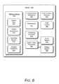
- FIG. 6illustrates various components of an example device 600 that can be implemented as any of the devices described with reference to the previous FIGS. 1-5 , such as a wearable display device and/or a controller for a wearable display device.
- the devicemay be implemented as any one or combination of a fixed or mobile device, in any form of a consumer, computer, portable, communication, phone, navigation, appliance, gaming, media playback, and/or electronic device.
- the devicemay also be associated with a user (i.e., a person) and/or an entity that operates the device such that a device describes logical devices that include users, software, firmware, hardware, and/or a combination of devices.
- the device 600includes communication devices 602 that enable wired and/or wireless communication of device data 604 , such as virtual image data, as well as video and images data, and other media content stored on the device.
- the media content stored on the devicecan include any type of audio, video, and/or image data.
- the deviceincludes one or more data inputs 606 via which any type of data, media content, and/or inputs can be received, such as user-selectable inputs and any other type of audio, video, and/or image data received from any content and/or data source.
- the device 600also includes communication interfaces 608 , such as any one or more of a serial, parallel, network, or wireless interface.
- the communication interfacesprovide a connection and/or communication links between the device and a communication network by which other electronic, computing, and communication devices communicate data with the device.
- the device 600includes one or more processors 610 (e.g., any of microprocessors, controllers, and the like), which process computer-executable instructions to control the operation of the device.
- processors 610e.g., any of microprocessors, controllers, and the like
- the devicecan be implemented with any one or combination of software, hardware, firmware, or fixed logic circuitry that is implemented in connection with processing and control circuits which are generally identified at 612 .
- the devicecan include a system bus or data transfer system that couples the various components within the device.
- a system buscan include any one or combination of different bus structures, such as a memory bus or memory controller, a peripheral bus, a universal serial bus, and/or a processor or local bus that utilizes any of a variety of bus architectures.
- the device 600also includes one or more memory devices 614 (e.g., computer-readable storage media) that enable data storage, such as random access memory (RAM), non-volatile memory (e.g., read-only memory (ROM), flash memory, etc.), and a disk storage device.
- RAMrandom access memory
- non-volatile memorye.g., read-only memory (ROM), flash memory, etc.
- a disk storage devicemay be implemented as any type of magnetic or optical storage device, such as a hard disk drive, a recordable and/or rewriteable disc, and the like.
- the devicemay also include a mass storage media device.
- Computer-readable storage mediacan be any available medium or media that is accessed by a computing device.
- a memory device 614provides data storage mechanisms to store the device data 604 , other types of information and/or data, and device applications 616 .
- an operating system 618can be maintained as a software application with the memory device and executed on the processors.
- the device applicationsmay also include a device manager or controller, such as any form of a control application, software application, signal processing and control module, code that is native to a particular device, a hardware abstraction layer for a particular device, and so on.
- the device applicationsalso include an imaging application 620 that implements embodiments of eyebox adjustment for interpupillary distance as described herein.
- the device 600may also include an audio and/or video processing system 622 that generates audio data for an audio system 624 and/or generates display data for a display system 626 .
- the audio system and/or the display systemare external components to the device.
- the audio system and/or the display systemare integrated components of the example device.
Landscapes
- Physics & Mathematics (AREA)
- General Physics & Mathematics (AREA)
- Optics & Photonics (AREA)
Abstract
Description
Claims (20)
Priority Applications (3)
| Application Number | Priority Date | Filing Date | Title |
|---|---|---|---|
| US13/343,675US8638498B2 (en) | 2012-01-04 | 2012-01-04 | Eyebox adjustment for interpupillary distance |
| PCT/US2012/071563WO2013103560A1 (en) | 2012-01-04 | 2012-12-23 | Eyebox adjustment for interpupillary distance |
| US14/134,993US9298012B2 (en) | 2012-01-04 | 2013-12-19 | Eyebox adjustment for interpupillary distance |
Applications Claiming Priority (1)
| Application Number | Priority Date | Filing Date | Title |
|---|---|---|---|
| US13/343,675US8638498B2 (en) | 2012-01-04 | 2012-01-04 | Eyebox adjustment for interpupillary distance |
Related Child Applications (1)
| Application Number | Title | Priority Date | Filing Date |
|---|---|---|---|
| US14/134,993ContinuationUS9298012B2 (en) | 2012-01-04 | 2013-12-19 | Eyebox adjustment for interpupillary distance |
Publications (2)
| Publication Number | Publication Date |
|---|---|
| US20130170031A1 US20130170031A1 (en) | 2013-07-04 |
| US8638498B2true US8638498B2 (en) | 2014-01-28 |
Family
ID=48694604
Family Applications (2)
| Application Number | Title | Priority Date | Filing Date |
|---|---|---|---|
| US13/343,675Active2032-03-09US8638498B2 (en) | 2012-01-04 | 2012-01-04 | Eyebox adjustment for interpupillary distance |
| US14/134,993ActiveUS9298012B2 (en) | 2012-01-04 | 2013-12-19 | Eyebox adjustment for interpupillary distance |
Family Applications After (1)
| Application Number | Title | Priority Date | Filing Date |
|---|---|---|---|
| US14/134,993ActiveUS9298012B2 (en) | 2012-01-04 | 2013-12-19 | Eyebox adjustment for interpupillary distance |
Country Status (2)
| Country | Link |
|---|---|
| US (2) | US8638498B2 (en) |
| WO (1) | WO2013103560A1 (en) |
Cited By (139)
| Publication number | Priority date | Publication date | Assignee | Title |
|---|---|---|---|---|
| US20130321245A1 (en)* | 2012-06-04 | 2013-12-05 | Fluor Technologies Corporation | Mobile device for monitoring and controlling facility systems |
| US8810600B2 (en) | 2012-01-23 | 2014-08-19 | Microsoft Corporation | Wearable display device calibration |
| US8917453B2 (en) | 2011-12-23 | 2014-12-23 | Microsoft Corporation | Reflective array waveguide |
| US20150022622A1 (en)* | 2013-07-17 | 2015-01-22 | Ebay Inc. | Methods, systems, and apparatus for providing video communications |
| US9223138B2 (en) | 2011-12-23 | 2015-12-29 | Microsoft Technology Licensing, Llc | Pixel opacity for augmented reality |
| US9298012B2 (en)* | 2012-01-04 | 2016-03-29 | Microsoft Technology Licensing, Llc | Eyebox adjustment for interpupillary distance |
| US9297996B2 (en) | 2012-02-15 | 2016-03-29 | Microsoft Technology Licensing, Llc | Laser illumination scanning |
| US9304235B2 (en) | 2014-07-30 | 2016-04-05 | Microsoft Technology Licensing, Llc | Microfabrication |
| US9366871B2 (en) | 2014-10-24 | 2016-06-14 | Emagin Corporation | Microdisplay based immersive headset |
| US9368546B2 (en) | 2012-02-15 | 2016-06-14 | Microsoft Technology Licensing, Llc | Imaging structure with embedded light sources |
| US9372347B1 (en) | 2015-02-09 | 2016-06-21 | Microsoft Technology Licensing, Llc | Display system |
| US9377623B2 (en) | 2014-08-11 | 2016-06-28 | Microsoft Technology Licensing, Llc | Waveguide eye tracking employing volume Bragg grating |
| US9423360B1 (en) | 2015-02-09 | 2016-08-23 | Microsoft Technology Licensing, Llc | Optical components |
| US9429692B1 (en) | 2015-02-09 | 2016-08-30 | Microsoft Technology Licensing, Llc | Optical components |
| US9459451B2 (en) | 2013-12-26 | 2016-10-04 | Microsoft Technology Licensing, Llc | Eye tracking apparatus, method and system |
| US9494799B2 (en) | 2014-09-24 | 2016-11-15 | Microsoft Technology Licensing, Llc | Waveguide eye tracking employing switchable diffraction gratings |
| US9513480B2 (en) | 2015-02-09 | 2016-12-06 | Microsoft Technology Licensing, Llc | Waveguide |
| US9535253B2 (en) | 2015-02-09 | 2017-01-03 | Microsoft Technology Licensing, Llc | Display system |
| US9578318B2 (en) | 2012-03-14 | 2017-02-21 | Microsoft Technology Licensing, Llc | Imaging structure emitter calibration |
| US9581820B2 (en) | 2012-06-04 | 2017-02-28 | Microsoft Technology Licensing, Llc | Multiple waveguide imaging structure |
| US9606586B2 (en) | 2012-01-23 | 2017-03-28 | Microsoft Technology Licensing, Llc | Heat transfer device |
| US9717981B2 (en) | 2012-04-05 | 2017-08-01 | Microsoft Technology Licensing, Llc | Augmented reality and physical games |
| US9726887B2 (en) | 2012-02-15 | 2017-08-08 | Microsoft Technology Licensing, Llc | Imaging structure color conversion |
| US9779643B2 (en) | 2012-02-15 | 2017-10-03 | Microsoft Technology Licensing, Llc | Imaging structure emitter configurations |
| US9827209B2 (en) | 2015-02-09 | 2017-11-28 | Microsoft Technology Licensing, Llc | Display system |
| US10018844B2 (en) | 2015-02-09 | 2018-07-10 | Microsoft Technology Licensing, Llc | Wearable image display system |
| US10192358B2 (en) | 2012-12-20 | 2019-01-29 | Microsoft Technology Licensing, Llc | Auto-stereoscopic augmented reality display |
| US10191515B2 (en) | 2012-03-28 | 2019-01-29 | Microsoft Technology Licensing, Llc | Mobile device light guide display |
| US10254942B2 (en) | 2014-07-31 | 2019-04-09 | Microsoft Technology Licensing, Llc | Adaptive sizing and positioning of application windows |
| US10317677B2 (en) | 2015-02-09 | 2019-06-11 | Microsoft Technology Licensing, Llc | Display system |
| US10388073B2 (en) | 2012-03-28 | 2019-08-20 | Microsoft Technology Licensing, Llc | Augmented reality light guide display |
| US10422989B2 (en)* | 2018-02-06 | 2019-09-24 | Microsoft Technology Licensing, Llc | Optical systems including a single actuator and multiple fluid-filled optical lenses for near-eye-display devices |
| US10496238B2 (en)* | 2016-08-22 | 2019-12-03 | University Of Rochester | 3D display ray principles and methods, zooming, and real-time demonstration |
| US10502876B2 (en) | 2012-05-22 | 2019-12-10 | Microsoft Technology Licensing, Llc | Waveguide optics focus elements |
| US10592080B2 (en) | 2014-07-31 | 2020-03-17 | Microsoft Technology Licensing, Llc | Assisted presentation of application windows |
| US10630965B2 (en) | 2015-10-02 | 2020-04-21 | Microsoft Technology Licensing, Llc | Calibrating a near-eye display |
| US10678412B2 (en) | 2014-07-31 | 2020-06-09 | Microsoft Technology Licensing, Llc | Dynamic joint dividers for application windows |
| US10739111B2 (en) | 2015-04-21 | 2020-08-11 | University Of Rochester | Cloaking systems and methods |
| US10866425B1 (en) | 2019-12-16 | 2020-12-15 | Microsoft Technology Licensing, Llc | Image reprojection based on intra-pupil distance |
| US11006090B2 (en) | 2016-08-05 | 2021-05-11 | University Of Rochester | Virtual window |
| US11068049B2 (en) | 2012-03-23 | 2021-07-20 | Microsoft Technology Licensing, Llc | Light guide display and field of view |
| US11086216B2 (en) | 2015-02-09 | 2021-08-10 | Microsoft Technology Licensing, Llc | Generating electronic components |
| US11438566B2 (en) | 2017-10-19 | 2022-09-06 | Intel Corporation | Three dimensional glasses free light field display using eye location |
| US11544888B2 (en) | 2019-06-06 | 2023-01-03 | Magic Leap, Inc. | Photoreal character configurations for spatial computing |
| US11550157B2 (en) | 2017-07-24 | 2023-01-10 | Mentor Acquisition One, Llc | See-through computer display systems |
| US11561615B2 (en) | 2017-04-14 | 2023-01-24 | Magic Leap, Inc. | Multimodal eye tracking |
| US11561613B2 (en) | 2020-05-29 | 2023-01-24 | Magic Leap, Inc. | Determining angular acceleration |
| US11567328B2 (en) | 2017-07-24 | 2023-01-31 | Mentor Acquisition One, Llc | See-through computer display systems with adjustable zoom cameras |
| US11587563B2 (en) | 2019-03-01 | 2023-02-21 | Magic Leap, Inc. | Determining input for speech processing engine |
| US11592669B2 (en) | 2016-03-02 | 2023-02-28 | Mentor Acquisition One, Llc | Optical systems for head-worn computers |
| US11592665B2 (en) | 2019-12-09 | 2023-02-28 | Magic Leap, Inc. | Systems and methods for operating a head-mounted display system based on user identity |
| US11599326B2 (en) | 2014-02-11 | 2023-03-07 | Mentor Acquisition One, Llc | Spatial location presentation in head worn computing |
| US11601484B2 (en) | 2011-10-28 | 2023-03-07 | Magic Leap, Inc. | System and method for augmented and virtual reality |
| US11619965B2 (en) | 2018-10-24 | 2023-04-04 | Magic Leap, Inc. | Asynchronous ASIC |
| US11619820B2 (en) | 2014-01-21 | 2023-04-04 | Mentor Acquisition One, Llc | See-through computer display systems |
| US11627430B2 (en) | 2019-12-06 | 2023-04-11 | Magic Leap, Inc. | Environment acoustics persistence |
| US11630315B2 (en) | 2014-08-12 | 2023-04-18 | Mentor Acquisition One, Llc | Measuring content brightness in head worn computing |
| US11632646B2 (en) | 2019-12-20 | 2023-04-18 | Magic Leap, Inc. | Physics-based audio and haptic synthesis |
| US11636843B2 (en) | 2020-05-29 | 2023-04-25 | Magic Leap, Inc. | Surface appropriate collisions |
| US11650416B2 (en) | 2014-01-21 | 2023-05-16 | Mentor Acquisition One, Llc | See-through computer display systems |
| US11651565B2 (en) | 2018-09-25 | 2023-05-16 | Magic Leap, Inc. | Systems and methods for presenting perspective views of augmented reality virtual object |
| US11651762B2 (en) | 2018-06-14 | 2023-05-16 | Magic Leap, Inc. | Reverberation gain normalization |
| US11657585B2 (en) | 2018-02-15 | 2023-05-23 | Magic Leap, Inc. | Mixed reality musical instrument |
| US11654074B2 (en) | 2016-02-29 | 2023-05-23 | Mentor Acquisition One, Llc | Providing enhanced images for navigation |
| US11663794B2 (en) | 2014-06-09 | 2023-05-30 | Mentor Acquisition One, Llc | Content presentation in head worn computing |
| US11668939B2 (en) | 2017-07-24 | 2023-06-06 | Mentor Acquisition One, Llc | See-through computer display systems with stray light management |
| US11669163B2 (en) | 2014-01-21 | 2023-06-06 | Mentor Acquisition One, Llc | Eye glint imaging in see-through computer display systems |
| US11696087B2 (en) | 2018-10-05 | 2023-07-04 | Magic Leap, Inc. | Emphasis for audio spatialization |
| US11699262B2 (en) | 2017-03-30 | 2023-07-11 | Magic Leap, Inc. | Centralized rendering |
| US11703755B2 (en) | 2017-05-31 | 2023-07-18 | Magic Leap, Inc. | Fiducial design |
| US11704874B2 (en) | 2019-08-07 | 2023-07-18 | Magic Leap, Inc. | Spatial instructions and guides in mixed reality |
| US11719934B2 (en) | 2014-01-21 | 2023-08-08 | Mentor Acquisition One, Llc | Suppression of stray light in head worn computing |
| US11722812B2 (en) | 2017-03-30 | 2023-08-08 | Magic Leap, Inc. | Non-blocking dual driver earphones |
| US11721303B2 (en) | 2015-02-17 | 2023-08-08 | Mentor Acquisition One, Llc | See-through computer display systems |
| US11727223B2 (en) | 2014-04-25 | 2023-08-15 | Mentor Acquisition One, Llc | Language translation with head-worn computing |
| US11736888B2 (en) | 2018-02-15 | 2023-08-22 | Magic Leap, Inc. | Dual listener positions for mixed reality |
| US11737666B2 (en) | 2014-01-21 | 2023-08-29 | Mentor Acquisition One, Llc | Eye imaging in head worn computing |
| US11754845B2 (en) | 2016-06-01 | 2023-09-12 | Mentor Acquisition One, Llc | Modular systems for head-worn computers |
| US11763559B2 (en) | 2020-02-14 | 2023-09-19 | Magic Leap, Inc. | 3D object annotation |
| US11768417B2 (en) | 2016-09-08 | 2023-09-26 | Mentor Acquisition One, Llc | Electrochromic systems for head-worn computer systems |
| US11770671B2 (en) | 2018-06-18 | 2023-09-26 | Magic Leap, Inc. | Spatial audio for interactive audio environments |
| US11778410B2 (en) | 2020-02-14 | 2023-10-03 | Magic Leap, Inc. | Delayed audio following |
| US11771915B2 (en) | 2016-12-30 | 2023-10-03 | Mentor Acquisition One, Llc | Head-worn therapy device |
| US11778411B2 (en) | 2018-10-05 | 2023-10-03 | Magic Leap, Inc. | Near-field audio rendering |
| US11778400B2 (en) | 2018-06-14 | 2023-10-03 | Magic Leap, Inc. | Methods and systems for audio signal filtering |
| US11778148B2 (en) | 2019-12-04 | 2023-10-03 | Magic Leap, Inc. | Variable-pitch color emitting display |
| US11778398B2 (en) | 2019-10-25 | 2023-10-03 | Magic Leap, Inc. | Reverberation fingerprint estimation |
| US11782529B2 (en) | 2014-01-17 | 2023-10-10 | Mentor Acquisition One, Llc | External user interface for head worn computing |
| US11782274B2 (en) | 2014-01-24 | 2023-10-10 | Mentor Acquisition One, Llc | Stray light suppression for head worn computing |
| US11790935B2 (en) | 2019-08-07 | 2023-10-17 | Magic Leap, Inc. | Voice onset detection |
| US11790617B2 (en) | 2014-06-09 | 2023-10-17 | Mentor Acquisition One, Llc | Content presentation in head worn computing |
| US11797720B2 (en) | 2020-02-14 | 2023-10-24 | Magic Leap, Inc. | Tool bridge |
| US11800313B2 (en) | 2020-03-02 | 2023-10-24 | Magic Leap, Inc. | Immersive audio platform |
| US11796805B2 (en) | 2014-01-21 | 2023-10-24 | Mentor Acquisition One, Llc | Eye imaging in head worn computing |
| US11800174B2 (en) | 2018-02-15 | 2023-10-24 | Magic Leap, Inc. | Mixed reality virtual reverberation |
| US11809628B2 (en) | 2014-12-03 | 2023-11-07 | Mentor Acquisition One, Llc | See-through computer display systems |
| US11809022B2 (en) | 2014-04-25 | 2023-11-07 | Mentor Acquisition One, Llc | Temple and ear horn assembly for headworn computer |
| US11816296B2 (en) | 2015-07-22 | 2023-11-14 | Mentor Acquisition One, Llc | External user interface for head worn computing |
| US11825257B2 (en) | 2016-08-22 | 2023-11-21 | Mentor Acquisition One, Llc | Speaker systems for head-worn computer systems |
| US11822090B2 (en) | 2014-01-24 | 2023-11-21 | Mentor Acquisition One, Llc | Haptic systems for head-worn computers |
| US11843931B2 (en) | 2018-06-12 | 2023-12-12 | Magic Leap, Inc. | Efficient rendering of virtual soundfields |
| US11854566B2 (en) | 2018-06-21 | 2023-12-26 | Magic Leap, Inc. | Wearable system speech processing |
| US11851177B2 (en) | 2014-05-06 | 2023-12-26 | Mentor Acquisition One, Llc | Unmanned aerial vehicle launch system |
| US11861803B2 (en) | 2020-02-14 | 2024-01-02 | Magic Leap, Inc. | Session manager |
| US11867537B2 (en) | 2015-05-19 | 2024-01-09 | Magic Leap, Inc. | Dual composite light field device |
| US11880041B2 (en) | 2014-04-25 | 2024-01-23 | Mentor Acquisition One, Llc | Speaker assembly for headworn computer |
| US11886638B2 (en) | 2015-07-22 | 2024-01-30 | Mentor Acquisition One, Llc | External user interface for head worn computing |
| US11886631B2 (en) | 2018-12-27 | 2024-01-30 | Magic Leap, Inc. | Systems and methods for virtual and augmented reality |
| US11895483B2 (en) | 2017-10-17 | 2024-02-06 | Magic Leap, Inc. | Mixed reality spatial audio |
| US11892644B2 (en) | 2014-01-21 | 2024-02-06 | Mentor Acquisition One, Llc | See-through computer display systems |
| US11900554B2 (en) | 2014-01-24 | 2024-02-13 | Mentor Acquisition One, Llc | Modification of peripheral content in world-locked see-through computer display systems |
| US11910183B2 (en) | 2020-02-14 | 2024-02-20 | Magic Leap, Inc. | Multi-application audio rendering |
| US11917384B2 (en) | 2020-03-27 | 2024-02-27 | Magic Leap, Inc. | Method of waking a device using spoken voice commands |
| US11936733B2 (en) | 2018-07-24 | 2024-03-19 | Magic Leap, Inc. | Application sharing |
| US11935180B2 (en) | 2019-10-18 | 2024-03-19 | Magic Leap, Inc. | Dual IMU SLAM |
| US11940629B2 (en) | 2014-07-08 | 2024-03-26 | Mentor Acquisition One, Llc | Optical configurations for head-worn see-through displays |
| US11947120B2 (en) | 2017-08-04 | 2024-04-02 | Mentor Acquisition One, Llc | Image expansion optic for head-worn computer |
| US11948256B2 (en) | 2018-10-09 | 2024-04-02 | Magic Leap, Inc. | Systems and methods for artificial intelligence-based virtual and augmented reality |
| US11961194B2 (en) | 2019-10-25 | 2024-04-16 | Magic Leap, Inc. | Non-uniform stereo rendering |
| US11960089B2 (en) | 2014-06-05 | 2024-04-16 | Mentor Acquisition One, Llc | Optical configurations for head-worn see-through displays |
| US11959997B2 (en) | 2019-11-22 | 2024-04-16 | Magic Leap, Inc. | System and method for tracking a wearable device |
| US11988837B2 (en) | 2018-04-24 | 2024-05-21 | Mentor Acquisition One, Llc | See-through computer display systems with vision correction and increased content density |
| US12050321B2 (en) | 2016-05-09 | 2024-07-30 | Mentor Acquisition One, Llc | User interface systems for head-worn computers |
| US12079938B2 (en) | 2020-02-10 | 2024-09-03 | Magic Leap, Inc. | Dynamic colocation of virtual content |
| US12093453B2 (en) | 2014-01-21 | 2024-09-17 | Mentor Acquisition One, Llc | Eye glint imaging in see-through computer display systems |
| US12105281B2 (en) | 2014-01-21 | 2024-10-01 | Mentor Acquisition One, Llc | See-through computer display systems |
| US12111473B2 (en) | 2016-09-08 | 2024-10-08 | Mentor Acquisition One, Llc | Optical systems for head-worn computers |
| US12112089B2 (en) | 2014-02-11 | 2024-10-08 | Mentor Acquisition One, Llc | Spatial location presentation in head worn computing |
| US12145505B2 (en) | 2014-03-28 | 2024-11-19 | Mentor Acquisition One, Llc | System for assisted operator safety using an HMD |
| US12174378B2 (en) | 2014-06-17 | 2024-12-24 | Mentor Acquisition One, Llc | External user interface for head worn computing |
| US20240427112A1 (en)* | 2020-04-27 | 2024-12-26 | Apple Inc. | Electronic Devices with Optical Module Positioning Systems |
| US12232688B2 (en) | 2014-07-15 | 2025-02-25 | Mentor Acquisition One, Llc | Content presentation in head worn computing |
| US12245097B2 (en) | 2019-03-25 | 2025-03-04 | Magic Leap, Inc. | Systems and methods for virtual and augmented reality |
| US12267654B2 (en) | 2018-05-30 | 2025-04-01 | Magic Leap, Inc. | Index scheming for filter parameters |
| US12277586B2 (en) | 2015-06-24 | 2025-04-15 | Magic Leap, Inc. | Augmented reality systems and methods for purchasing |
| US12306413B2 (en) | 2021-03-12 | 2025-05-20 | Magic Leap , Inc. | Athermalization concepts for polymer eyepieces used in augmented reality or mixed reality devices |
| US12327573B2 (en) | 2019-04-19 | 2025-06-10 | Magic Leap, Inc. | Identifying input for speech recognition engine |
| US12417766B2 (en) | 2020-09-30 | 2025-09-16 | Magic Leap, Inc. | Voice user interface using non-linguistic input |
| US12443294B2 (en) | 2024-06-24 | 2025-10-14 | Mentor Acquisition One, Llc | External user interface for head worn computing |
Families Citing this family (95)
| Publication number | Priority date | Publication date | Assignee | Title |
|---|---|---|---|---|
| GB0718706D0 (en) | 2007-09-25 | 2007-11-07 | Creative Physics Ltd | Method and apparatus for reducing laser speckle |
| US11726332B2 (en) | 2009-04-27 | 2023-08-15 | Digilens Inc. | Diffractive projection apparatus |
| US9335604B2 (en) | 2013-12-11 | 2016-05-10 | Milan Momcilo Popovich | Holographic waveguide display |
| US8233204B1 (en) | 2009-09-30 | 2012-07-31 | Rockwell Collins, Inc. | Optical displays |
| US10795160B1 (en) | 2014-09-25 | 2020-10-06 | Rockwell Collins, Inc. | Systems for and methods of using fold gratings for dual axis expansion |
| US11320571B2 (en) | 2012-11-16 | 2022-05-03 | Rockwell Collins, Inc. | Transparent waveguide display providing upper and lower fields of view with uniform light extraction |
| US11300795B1 (en) | 2009-09-30 | 2022-04-12 | Digilens Inc. | Systems for and methods of using fold gratings coordinated with output couplers for dual axis expansion |
| US8659826B1 (en) | 2010-02-04 | 2014-02-25 | Rockwell Collins, Inc. | Worn display system and method without requiring real time tracking for boresight precision |
| WO2012136970A1 (en) | 2011-04-07 | 2012-10-11 | Milan Momcilo Popovich | Laser despeckler based on angular diversity |
| WO2016020630A2 (en) | 2014-08-08 | 2016-02-11 | Milan Momcilo Popovich | Waveguide laser illuminator incorporating a despeckler |
| EP2995986B1 (en) | 2011-08-24 | 2017-04-12 | Rockwell Collins, Inc. | Data display |
| US10670876B2 (en) | 2011-08-24 | 2020-06-02 | Digilens Inc. | Waveguide laser illuminator incorporating a despeckler |
| US9715067B1 (en) | 2011-09-30 | 2017-07-25 | Rockwell Collins, Inc. | Ultra-compact HUD utilizing waveguide pupil expander with surface relief gratings in high refractive index materials |
| US9366864B1 (en) | 2011-09-30 | 2016-06-14 | Rockwell Collins, Inc. | System for and method of displaying information without need for a combiner alignment detector |
| US9507150B1 (en) | 2011-09-30 | 2016-11-29 | Rockwell Collins, Inc. | Head up display (HUD) using a bent waveguide assembly |
| US8634139B1 (en) | 2011-09-30 | 2014-01-21 | Rockwell Collins, Inc. | System for and method of catadioptric collimation in a compact head up display (HUD) |
| US20150010265A1 (en) | 2012-01-06 | 2015-01-08 | Milan, Momcilo POPOVICH | Contact image sensor using switchable bragg gratings |
| US9116337B1 (en)* | 2012-03-21 | 2015-08-25 | Google Inc. | Increasing effective eyebox size of an HMD |
| US9523852B1 (en) | 2012-03-28 | 2016-12-20 | Rockwell Collins, Inc. | Micro collimator system and method for a head up display (HUD) |
| CN106125308B (en) | 2012-04-25 | 2019-10-25 | 罗克韦尔柯林斯公司 | Device and method for displaying images |
| US9933684B2 (en) | 2012-11-16 | 2018-04-03 | Rockwell Collins, Inc. | Transparent waveguide display providing upper and lower fields of view having a specific light output aperture configuration |
| EP2979446A1 (en)* | 2013-03-26 | 2016-02-03 | Seiko Epson Corporation | Head-mounted display device, control method of head-mounted display device, and display system |
| US9674413B1 (en) | 2013-04-17 | 2017-06-06 | Rockwell Collins, Inc. | Vision system and method having improved performance and solar mitigation |
| EP3023829A4 (en) | 2013-07-16 | 2017-05-10 | Sony Corporation | Display device |
| WO2015015138A1 (en) | 2013-07-31 | 2015-02-05 | Milan Momcilo Popovich | Method and apparatus for contact image sensing |
| US9244281B1 (en) | 2013-09-26 | 2016-01-26 | Rockwell Collins, Inc. | Display system and method using a detached combiner |
| US10732407B1 (en) | 2014-01-10 | 2020-08-04 | Rockwell Collins, Inc. | Near eye head up display system and method with fixed combiner |
| US9519089B1 (en) | 2014-01-30 | 2016-12-13 | Rockwell Collins, Inc. | High performance volume phase gratings |
| US9313481B2 (en) | 2014-02-19 | 2016-04-12 | Microsoft Technology Licensing, Llc | Stereoscopic display responsive to focal-point shift |
| US9244280B1 (en) | 2014-03-25 | 2016-01-26 | Rockwell Collins, Inc. | Near eye display system and method for display enhancement or redundancy |
| US10359736B2 (en) | 2014-08-08 | 2019-07-23 | Digilens Inc. | Method for holographic mastering and replication |
| WO2016042283A1 (en) | 2014-09-19 | 2016-03-24 | Milan Momcilo Popovich | Method and apparatus for generating input images for holographic waveguide displays |
| US10088675B1 (en) | 2015-05-18 | 2018-10-02 | Rockwell Collins, Inc. | Turning light pipe for a pupil expansion system and method |
| US9715110B1 (en) | 2014-09-25 | 2017-07-25 | Rockwell Collins, Inc. | Automotive head up display (HUD) |
| US20160103330A1 (en)* | 2014-10-10 | 2016-04-14 | 3DOO, Inc. | System and method for adjusting parallax in three-dimensional stereoscopic image representation |
| WO2016113534A1 (en) | 2015-01-12 | 2016-07-21 | Milan Momcilo Popovich | Environmentally isolated waveguide display |
| US9632226B2 (en) | 2015-02-12 | 2017-04-25 | Digilens Inc. | Waveguide grating device |
| US11468639B2 (en)* | 2015-02-20 | 2022-10-11 | Microsoft Technology Licensing, Llc | Selective occlusion system for augmented reality devices |
| US11956414B2 (en)* | 2015-03-17 | 2024-04-09 | Raytrx, Llc | Wearable image manipulation and control system with correction for vision defects and augmentation of vision and sensing |
| CN104822061A (en)* | 2015-04-30 | 2015-08-05 | 小鸟科技有限公司 | Interpupillary distance adjusting method, system, and module of head-mounted 3D display |
| US10126552B2 (en) | 2015-05-18 | 2018-11-13 | Rockwell Collins, Inc. | Micro collimator system and method for a head up display (HUD) |
| US11366316B2 (en) | 2015-05-18 | 2022-06-21 | Rockwell Collins, Inc. | Head up display (HUD) using a light pipe |
| US10247943B1 (en) | 2015-05-18 | 2019-04-02 | Rockwell Collins, Inc. | Head up display (HUD) using a light pipe |
| US10038887B2 (en) | 2015-05-27 | 2018-07-31 | Google Llc | Capture and render of panoramic virtual reality content |
| KR102023587B1 (en) | 2015-05-27 | 2019-09-23 | 구글 엘엘씨 | Camera Rig and Stereoscopic Image Capture |
| US9877016B2 (en) | 2015-05-27 | 2018-01-23 | Google Llc | Omnistereo capture and render of panoramic virtual reality content |
| WO2016191950A1 (en)* | 2015-05-29 | 2016-12-08 | 深圳市柔宇科技有限公司 | Display adjustment method and head-mounted display device |
| CN105049598B (en)* | 2015-06-01 | 2019-11-05 | 广东小天才科技有限公司 | A method and mobile terminal for detecting user vision distance |
| US10108010B2 (en) | 2015-06-29 | 2018-10-23 | Rockwell Collins, Inc. | System for and method of integrating head up displays and head down displays |
| JP6779984B2 (en)* | 2015-09-05 | 2020-11-04 | レイア、インコーポレイテッドLeia Inc. | Condensing backlight and near-eye display system using it |
| CN113759555B (en) | 2015-10-05 | 2024-09-20 | 迪吉伦斯公司 | Waveguide Display |
| KR102348588B1 (en) | 2015-10-16 | 2022-01-07 | 레이아 인코포레이티드 | Multibeam diffraction grating-based near-eye display |
| US10598932B1 (en) | 2016-01-06 | 2020-03-24 | Rockwell Collins, Inc. | Head up display for integrating views of conformally mapped symbols and a fixed image source |
| US20170212361A1 (en)* | 2016-01-25 | 2017-07-27 | Terrence A. Staton | Optimal Focusing Design for High Field of View Head Mount Displays |
| US20190018186A1 (en) | 2016-01-30 | 2019-01-17 | Leia Inc. | Privacy display and dual-mode privacy display system |
| CN108780224B (en) | 2016-03-24 | 2021-08-03 | 迪吉伦斯公司 | Method and apparatus for providing a polarization selective holographic waveguide device |
| CN107272319A (en)* | 2016-04-07 | 2017-10-20 | 中强光电股份有限公司 | Projection device and image projection method |
| US10890707B2 (en) | 2016-04-11 | 2021-01-12 | Digilens Inc. | Holographic waveguide apparatus for structured light projection |
| US10215986B2 (en)* | 2016-05-16 | 2019-02-26 | Microsoft Technology Licensing, Llc | Wedges for light transformation |
| US20170344107A1 (en)* | 2016-05-25 | 2017-11-30 | Intel Corporation | Automatic view adjustments for computing devices based on interpupillary distances associated with their users |
| CN109643515B (en) | 2016-08-15 | 2022-07-12 | 苹果公司 | Display with variable resolution |
| US10690991B1 (en) | 2016-09-02 | 2020-06-23 | Apple Inc. | Adjustable lens systems |
| JP6741643B2 (en)* | 2016-12-01 | 2020-08-19 | ヴァルヨ テクノロジーズ オーユー | Display device and display method using context display and projector |
| US9711114B1 (en)* | 2016-12-01 | 2017-07-18 | Varjo Technologies Oy | Display apparatus and method of displaying using projectors |
| US9711072B1 (en)* | 2016-12-01 | 2017-07-18 | Varjo Technologies Oy | Display apparatus and method of displaying using focus and context displays |
| WO2018102834A2 (en) | 2016-12-02 | 2018-06-07 | Digilens, Inc. | Waveguide device with uniform output illumination |
| US10545346B2 (en) | 2017-01-05 | 2020-01-28 | Digilens Inc. | Wearable heads up displays |
| US10295824B2 (en) | 2017-01-26 | 2019-05-21 | Rockwell Collins, Inc. | Head up display with an angled light pipe |
| US10620432B1 (en)* | 2017-04-25 | 2020-04-14 | Facebook Technologies, Llc | Devices and methods for lens position adjustment based on diffraction in a fresnel lens |
| US10520729B1 (en)* | 2017-04-25 | 2019-12-31 | Facebook Technologies, Llc | Light scattering element for providing optical cues for lens position adjustment |
| US10488920B2 (en)* | 2017-06-02 | 2019-11-26 | Htc Corporation | Immersive headset system and control method thereof |
| TWI697692B (en)* | 2017-08-01 | 2020-07-01 | 緯創資通股份有限公司 | Near eye display system and operation method thereof |
| US10925484B2 (en) | 2017-09-14 | 2021-02-23 | Orthozon Technologies, Llc | Interpupillary calibration system, apparatus, and method for stereoscopic visualization |
| WO2019079350A2 (en) | 2017-10-16 | 2019-04-25 | Digilens, Inc. | Systems and methods for multiplying the image resolution of a pixelated display |
| WO2019136476A1 (en) | 2018-01-08 | 2019-07-11 | Digilens, Inc. | Waveguide architectures and related methods of manufacturing |
| EP3710894B1 (en) | 2018-01-08 | 2025-07-30 | Digilens Inc. | Methods for fabricating optical waveguides |
| EP3710876A4 (en) | 2018-01-08 | 2022-02-09 | DigiLens Inc. | SYSTEMS AND METHODS OF FABRICATING WAVEGUIDE CELLS |
| US10732569B2 (en) | 2018-01-08 | 2020-08-04 | Digilens Inc. | Systems and methods for high-throughput recording of holographic gratings in waveguide cells |
| US20210239975A1 (en)* | 2018-06-11 | 2021-08-05 | Shimadzu Corporation | Image display device |
| US10838203B2 (en) | 2018-07-17 | 2020-11-17 | Apple Inc. | Adjustable electronic device system with facial mapping |
| WO2020023779A1 (en) | 2018-07-25 | 2020-01-30 | Digilens Inc. | Systems and methods for fabricating a multilayer optical structure |
| US20200211512A1 (en)* | 2018-12-27 | 2020-07-02 | Facebook Technologies, Llc | Headset adjustment for optimal viewing |
| US20200225471A1 (en) | 2019-01-14 | 2020-07-16 | Digilens Inc. | Holographic Waveguide Display with Light Control Layer |
| US20200247017A1 (en) | 2019-02-05 | 2020-08-06 | Digilens Inc. | Methods for Compensating for Optical Surface Nonuniformity |
| KR102866596B1 (en) | 2019-02-15 | 2025-09-29 | 디지렌즈 인코포레이티드. | Method and device for providing a holographic waveguide display using an integral grating |
| US20220283377A1 (en) | 2019-02-15 | 2022-09-08 | Digilens Inc. | Wide Angle Waveguide Display |
| KR102771619B1 (en) | 2019-03-11 | 2025-02-25 | 삼성전자주식회사 | Display apparatus capable of laterally shifting image |
| WO2020186113A1 (en) | 2019-03-12 | 2020-09-17 | Digilens Inc. | Holographic waveguide backlight and related methods of manufacturing |
| US11092324B2 (en)* | 2019-03-28 | 2021-08-17 | GM Global Technology Operations LLC | Semi-transparent sign temperature protection |
| EP3980825A4 (en) | 2019-06-07 | 2023-05-03 | Digilens Inc. | WAVEGUIDES WITH TRANSMITTING AND REFLECTING GRIDS AND RELATED MANUFACTURING PROCESSES |
| EP4004646A4 (en) | 2019-07-29 | 2023-09-06 | Digilens Inc. | METHODS AND APPARATUS FOR MULTIPLYING THE IMAGE RESOLUTION AND FIELD OF VIEW OF A PIXELATED DISPLAY SCREEN |
| KR102775783B1 (en) | 2019-08-29 | 2025-02-28 | 디지렌즈 인코포레이티드. | Vacuum grid and method for manufacturing the same |
| US11763779B1 (en)* | 2020-04-23 | 2023-09-19 | Apple Inc. | Head-mounted display systems with alignment monitoring |
| WO2022150841A1 (en) | 2021-01-07 | 2022-07-14 | Digilens Inc. | Grating structures for color waveguides |
| US12158612B2 (en) | 2021-03-05 | 2024-12-03 | Digilens Inc. | Evacuated periodic structures and methods of manufacturing |
Citations (66)
| Publication number | Priority date | Publication date | Assignee | Title |
|---|---|---|---|---|
| WO1994018595A1 (en) | 1993-02-01 | 1994-08-18 | Honeywell Inc. | Visor display with fiber optic faceplate correction |
| US5459611A (en) | 1993-08-18 | 1995-10-17 | Hewlett-Packard Company | Beam splitter/combiner with path length compensator and method for making the same |
| JPH07311303A (en) | 1994-05-16 | 1995-11-28 | Asahi Optical Co Ltd | Beam splitting element |
| US5483307A (en) | 1994-09-29 | 1996-01-09 | Texas Instruments, Inc. | Wide field of view head-mounted display |
| US5574473A (en)* | 1993-08-26 | 1996-11-12 | Olympus Optical Co., Ltd. | Image display apparatus |
| US5583609A (en) | 1993-04-23 | 1996-12-10 | Nikon Corporation | Projection exposure apparatus |
| US5614941A (en) | 1993-11-24 | 1997-03-25 | Hines; Stephen P. | Multi-image autostereoscopic imaging system |
| US5673146A (en) | 1994-08-09 | 1997-09-30 | Kelly; Shawn L. | Binocular imaging system |
| US5751476A (en) | 1995-02-28 | 1998-05-12 | Sony Corporation | Display device |
| US5982553A (en) | 1997-03-20 | 1999-11-09 | Silicon Light Machines | Display device incorporating one-dimensional grating light-valve array |
| US6160667A (en) | 1997-08-11 | 2000-12-12 | Telcordia Technologies, Inc. | Apparatus and method for creating and displaying planar virtual images |
| JP2001078234A (en) | 1999-09-07 | 2001-03-23 | Mixed Reality Systems Laboratory Inc | Image input device and image display device |
| US6271808B1 (en) | 1998-06-05 | 2001-08-07 | Silicon Light Machines | Stereo head mounted display using a single display device |
| WO2001095027A2 (en) | 2000-06-05 | 2001-12-13 | Lumus Ltd. | Substrate-guided optical beam expander |
| US6377401B1 (en) | 1999-07-28 | 2002-04-23 | Bae Systems Electronics Limited | Head tracker system |
| US6529331B2 (en) | 2001-04-20 | 2003-03-04 | Johns Hopkins University | Head mounted display with full field of view and high resolution |
| US6554428B2 (en) | 2000-09-07 | 2003-04-29 | I-O Display Systems Llc | Method and apparatus for adjusting optical device to correspond to eye positions |
| US6639201B2 (en) | 2001-11-07 | 2003-10-28 | Applied Materials, Inc. | Spot grid array imaging system |
| WO2003090611A1 (en) | 2002-04-25 | 2003-11-06 | E-Vision, Llc | Electro-active multi-focal spectacle lens |
| US20040085649A1 (en) | 2002-07-17 | 2004-05-06 | C.R.F. Societa Consortile Per Azioni | Light guide for display devices of the head-mounted or head-up type |
| US6775460B2 (en) | 1998-07-07 | 2004-08-10 | Honeywell International Inc. | Optical array and collimated light distribution |
| US6919867B2 (en) | 2001-03-29 | 2005-07-19 | Siemens Corporate Research, Inc. | Method and apparatus for augmented reality visualization |
| US6947020B2 (en) | 2002-05-23 | 2005-09-20 | Oregonlabs, Llc | Multi-array spatial light modulating devices and methods of fabrication |
| US6964731B1 (en) | 1998-12-21 | 2005-11-15 | Cardinal Cg Company | Soil-resistant coating for glass surfaces |
| US20060018025A1 (en) | 2003-01-08 | 2006-01-26 | Explay Ltd. | Image projecting device and method |
| US7015876B1 (en) | 1998-06-03 | 2006-03-21 | Lear Corporation | Heads-up display with improved contrast |
| US7048385B2 (en) | 2004-06-16 | 2006-05-23 | Goldeneye, Inc. | Projection display systems utilizing color scrolling and light emitting diodes |
| JP2008017135A (en) | 2006-07-05 | 2008-01-24 | Brother Ind Ltd | Image processing apparatus and image processing method |
| US20080043100A1 (en) | 2006-07-31 | 2008-02-21 | Irwin Sobel | Projection screen and camera array |
| US7359420B2 (en) | 2004-07-30 | 2008-04-15 | Arasor Corporation | Manufacturable vertical extended cavity surface emitting laser arrays |
| US7369101B2 (en) | 2003-06-12 | 2008-05-06 | Siemens Medical Solutions Usa, Inc. | Calibrating real and virtual views |
| US7417617B2 (en) | 1999-05-18 | 2008-08-26 | Dimension Technologies, Inc. | Enhanced resolution for image generation |
| US7430355B2 (en) | 2003-12-08 | 2008-09-30 | University Of Cincinnati | Light emissive signage devices based on lightwave coupling |
| US7430349B2 (en) | 2004-02-13 | 2008-09-30 | Lockheed Martin Corporation | Method for increasing daylight display brightness for helmet mounted displays |
| US20080311386A1 (en) | 2002-11-27 | 2008-12-18 | Karl-Heinz Wendt | Coated Glasses and Method for their Manufacture |
| US20090051283A1 (en) | 2007-08-21 | 2009-02-26 | Cok Ronald S | Led device having improved contrast |
| US7542665B2 (en) | 2006-02-24 | 2009-06-02 | Tianmo Lei | Fully automatic, head mounted, hand and eye free camera system and photography |
| KR20090076539A (en) | 2008-01-09 | 2009-07-13 | 에스케이 텔레콤주식회사 | 3D image display device and method of adjusting display unit position in 3D image display device |
| US20090190003A1 (en) | 2004-07-30 | 2009-07-30 | Industry-University Cooperation Foundation Hanyang University | Vision-based augmented reality system using invisible marker |
| US7660500B2 (en) | 2007-05-22 | 2010-02-09 | Epicrystals Oy | Light emitting array |
| US20100061078A1 (en) | 2008-09-10 | 2010-03-11 | Samsung Electronics Co., Ltd. | Light emitting device and system providing white light with various color temperatures |
| US20100060551A1 (en) | 2007-09-26 | 2010-03-11 | Keiji Sugiyama | Beam scanning-type display device, method, program and integrated circuit |
| US20100084674A1 (en) | 2007-02-27 | 2010-04-08 | Ralph Paetzold | OLED with Color Conversion |
| US7777944B2 (en) | 2006-06-08 | 2010-08-17 | Delta Electronics, Inc. | Reflective screens |
| US20100213467A1 (en) | 2007-08-16 | 2010-08-26 | The Trustees Of Columbia University In The City Of New York | Direct bandgap substrates and methods of making and using |
| US20100229853A1 (en) | 2009-01-13 | 2010-09-16 | Vandal Robert A | Mounting brackets for mirrors, and associated methods |
| US20100245387A1 (en) | 2005-04-11 | 2010-09-30 | Systems Technology, Inc. | Systems and methods for combining virtual and real-time physical environments |
| US20100317132A1 (en) | 2009-05-12 | 2010-12-16 | Rogers John A | Printed Assemblies of Ultrathin, Microscale Inorganic Light Emitting Diodes for Deformable and Semitransparent Displays |
| US20110012814A1 (en) | 2009-07-15 | 2011-01-20 | Brother Kogyo Kabushiki Kaisha | Adjustable Attachment for Attaching Head-Mounted Display to Eyeglasses-Type Frame |
| US20110032482A1 (en) | 2009-08-07 | 2011-02-10 | Light Prescriptions Innovators, Llc | 3d autostereoscopic display with true depth perception |
| US20110050655A1 (en) | 2009-08-31 | 2011-03-03 | Sony Corporation | Image display apparatus and head mounted display |
| US20110091156A1 (en) | 2009-10-15 | 2011-04-21 | Laughlin Richard H | Environmentally rugged free-space fiber waveguide connector and method of manufacture thereof |
| US20110090343A1 (en) | 2008-03-27 | 2011-04-21 | Metaio Gmbh | Composite image generating system, overlaying condition determining method, image processing apparatus, and image processing program |
| US20110194029A1 (en) | 2010-02-05 | 2011-08-11 | Kopin Corporation | Touch sensor for controlling eyewear |
| US20110221659A1 (en) | 2010-02-28 | 2011-09-15 | Osterhout Group, Inc. | Augmented reality eyepiece with freeform optic, image source, and optical display |
| US20110267799A1 (en) | 2004-06-01 | 2011-11-03 | 3M Innovative Properties Company | LED Array Systems |
| US20110299044A1 (en) | 2009-06-22 | 2011-12-08 | Industrial Technology Research Institute | Projection apparatus |
| US20110309378A1 (en) | 2009-12-09 | 2011-12-22 | Nano And Advanced Materials Institute Limited | Method for manufacturing a monolithic led micro-display on an active matrix panel using flip-chip technology and display apparatus having the monolithic led micro-display |
| US20130162673A1 (en) | 2011-12-23 | 2013-06-27 | David D. Bohn | Pixel opacity for augmented reality |
| US20130163089A1 (en) | 2011-12-23 | 2013-06-27 | David D. Bohn | Reflective array waveguide |
| US20130170031A1 (en) | 2012-01-04 | 2013-07-04 | David D. Bohn | Eyebox adjustment for interpupillary distance |
| US20130187943A1 (en) | 2012-01-23 | 2013-07-25 | David D. Bohn | Wearable display device calibration |
| US20130208482A1 (en) | 2012-02-15 | 2013-08-15 | Rod G. Fleck | Imaging structure color conversion |
| US20130208362A1 (en) | 2012-02-15 | 2013-08-15 | David D. Bohn | Laser illumination scanning |
| US20130208003A1 (en) | 2012-02-15 | 2013-08-15 | David D. Bohn | Imaging structure emitter configurations |
| US20130207964A1 (en) | 2012-02-15 | 2013-08-15 | Rod G. Fleck | Imaging structure with embedded light sources |
Family Cites Families (77)
| Publication number | Priority date | Publication date | Assignee | Title |
|---|---|---|---|---|
| US3971065A (en) | 1975-03-05 | 1976-07-20 | Eastman Kodak Company | Color imaging array |
| US5252950A (en) | 1991-12-20 | 1993-10-12 | Apple Computer, Inc. | Display with rangefinder |
| US6008781A (en) | 1992-10-22 | 1999-12-28 | Board Of Regents Of The University Of Washington | Virtual retinal display |
| US5359444A (en)* | 1992-12-24 | 1994-10-25 | Motorola, Inc. | Auto-focusing optical apparatus |
| US5455882A (en) | 1993-09-29 | 1995-10-03 | Associated Universities, Inc. | Interactive optical panel |
| AU686245B2 (en) | 1993-10-07 | 1998-02-05 | Virtual Vision, Inc. | Binocular head mounted display system |
| US5714967A (en) | 1994-05-16 | 1998-02-03 | Olympus Optical Co., Ltd. | Head-mounted or face-mounted image display apparatus with an increased exit pupil |
| US5648643A (en) | 1995-06-16 | 1997-07-15 | Knowles; Terence J. | Acoustic wave touch panel with inlayed, etched arrays and method of making the panel |
| US6577411B1 (en) | 1996-11-12 | 2003-06-10 | Planop-Planar Optics Ltd. | Optical system for alternative or simultaneous direction of light originating from two scenes to the eye of a viewer |
| JPH10232626A (en) | 1997-02-20 | 1998-09-02 | Canon Inc | 3D image display device |
| US6188427B1 (en) | 1997-04-23 | 2001-02-13 | Texas Instruments Incorporated | Illumination system having an intensity calibration system |
| AU4976099A (en) | 1998-10-16 | 2000-05-08 | Digilens Inc. | Autostereoscopic display based on electrically switchable holograms |
| HUP0000532A2 (en) | 2000-02-07 | 2002-03-28 | Optilink Ab | Method and system for recording information on a holographic card |
| US6753828B2 (en) | 2000-09-25 | 2004-06-22 | Siemens Corporated Research, Inc. | System and method for calibrating a stereo optical see-through head-mounted display system for augmented reality |
| KR100406945B1 (en) | 2001-02-19 | 2003-11-28 | 삼성전자주식회사 | Wearable display apparatus |
| KR20020083737A (en) | 2001-04-30 | 2002-11-04 | 삼성전자 주식회사 | Wearable display system |
| US7009163B2 (en) | 2001-06-22 | 2006-03-07 | Orbotech Ltd. | High-sensitivity optical scanning using memory integration |
| US20030000689A1 (en) | 2001-06-29 | 2003-01-02 | Dah-Chyi Kuo | Heat dissipater |
| US20040135209A1 (en) | 2002-02-05 | 2004-07-15 | Tzu-Chiang Hsieh | Camera with MOS or CMOS sensor array |
| US7196391B2 (en) | 2002-02-05 | 2007-03-27 | E-Phocus, Inc. | MOS or CMOS sensor with micro-lens array |
| US6930053B2 (en) | 2002-03-25 | 2005-08-16 | Sanyo Electric Co., Ltd. | Method of forming grating microstructures by anodic oxidation |
| TW537436U (en) | 2002-05-31 | 2003-06-11 | Quanta Comp Inc | Three-phase variable heat conducting structure |
| US6631755B1 (en) | 2002-07-17 | 2003-10-14 | Compal Electronics, Inc. | Thermal module with temporary heat storage |
| CN100414694C (en) | 2002-08-21 | 2008-08-27 | 三星电子株式会社 | Flat plate heat transfer device and manufacturing method thereof |
| US6867753B2 (en) | 2002-10-28 | 2005-03-15 | University Of Washington | Virtual image registration in augmented display field |
| KR100490322B1 (en) | 2003-04-07 | 2005-05-17 | 삼성전자주식회사 | Organic electro-luminescent display |
| US7518804B2 (en) | 2003-04-24 | 2009-04-14 | Bae Systems Information And Electronic Systems Integration Inc. | Singlet telescopes with controllable ghosts for laser beam forming |
| US7184265B2 (en) | 2003-05-29 | 2007-02-27 | Lg Electronics Inc. | Cooling system for a portable computer |
| US7057339B2 (en) | 2004-04-08 | 2006-06-06 | Eastman Kodak Company | OLED with color change media |
| US7411589B2 (en) | 2004-04-30 | 2008-08-12 | Honeywell International Inc. | Liquid crystal color display system and method |
| US9030532B2 (en) | 2004-08-19 | 2015-05-12 | Microsoft Technology Licensing, Llc | Stereoscopic image display |
| US20060054782A1 (en) | 2004-08-25 | 2006-03-16 | Olsen Richard I | Apparatus for multiple camera devices and method of operating same |
| US20060044399A1 (en) | 2004-09-01 | 2006-03-02 | Eastman Kodak Company | Control system for an image capture device |
| JP4965800B2 (en)* | 2004-10-01 | 2012-07-04 | キヤノン株式会社 | Image display system |
| US9083781B2 (en) | 2004-11-15 | 2015-07-14 | Bascule Development Ag Llc | Portable image-capturing device with embedded projector |
| US20060139447A1 (en) | 2004-12-23 | 2006-06-29 | Unkrich Mark A | Eye detection system and method for control of a three-dimensional display |
| US8164622B2 (en) | 2005-07-01 | 2012-04-24 | Aperio Technologies, Inc. | System and method for single optical axis multi-detector microscope slide scanner |
| JP2007043078A (en) | 2005-07-04 | 2007-02-15 | Nuflare Technology Inc | Drawing apparatus and drawing method |
| JP5245195B2 (en) | 2005-11-14 | 2013-07-24 | ソニー株式会社 | Pixel circuit |
| IL174170A (en) | 2006-03-08 | 2015-02-26 | Abraham Aharoni | Device and method for binocular alignment |
| RU2449493C2 (en) | 2006-03-31 | 2012-04-27 | Конинклейке Филипс Электроникс Н.В. | Displaying instrument with generation of ambient illumination using switched panel |
| JP4827654B2 (en) | 2006-08-11 | 2011-11-30 | キヤノン株式会社 | Scanning image display device |
| CN101193535B (en) | 2006-12-01 | 2011-07-27 | 富准精密工业(深圳)有限公司 | Heat pipe radiator |
| US8491121B2 (en) | 2007-10-09 | 2013-07-23 | Elbit Systems Of America, Llc | Pupil scan apparatus |
| US7981591B2 (en) | 2008-03-27 | 2011-07-19 | Corning Incorporated | Semiconductor buried grating fabrication method |
| US20100149073A1 (en) | 2008-11-02 | 2010-06-17 | David Chaum | Near to Eye Display System and Appliance |
| DK2294496T3 (en) | 2008-05-21 | 2017-10-02 | Asetek As | Thermal insertion component for graphics card |
| US20100053151A1 (en) | 2008-09-02 | 2010-03-04 | Samsung Electronics Co., Ltd | In-line mediation for manipulating three-dimensional content on a display device |
| JP4636164B2 (en) | 2008-10-23 | 2011-02-23 | ソニー株式会社 | Head-mounted display |
| WO2010060211A1 (en) | 2008-11-28 | 2010-06-03 | Nortel Networks Limited | Method and apparatus for controling a camera view into a three dimensional computer-generated virtual environment |
| WO2010065820A1 (en) | 2008-12-05 | 2010-06-10 | Vuzix Corporation | Controllable light array for projection image display |
| US20100238270A1 (en) | 2009-03-20 | 2010-09-23 | Intrepid Management Group, Inc. | Endoscopic apparatus and method for producing via a holographic optical element an autostereoscopic 3-d image |
| US8649554B2 (en) | 2009-05-01 | 2014-02-11 | Microsoft Corporation | Method to control perspective for a camera-controlled computer |
| US20110021251A1 (en) | 2009-07-22 | 2011-01-27 | Sony Ericsson Mobile Communications Ab | Electronic device with touch-sensitive control |
| US9204373B2 (en) | 2009-08-28 | 2015-12-01 | Blackberry Limited | Method and system for acquisition of neighbour cell information |
| WO2011044936A1 (en) | 2009-10-14 | 2011-04-21 | Nokia Corporation | Autostereoscopic rendering and display apparatus |
| US8885112B2 (en) | 2009-10-27 | 2014-11-11 | Sbg Labs, Inc. | Compact holographic edge illuminated eyeglass display |
| JP2011209489A (en) | 2010-03-30 | 2011-10-20 | Renesas Electronics Corp | Display device, differential amplifier circuit, and data line drive method for display device |
| JP5499854B2 (en) | 2010-04-08 | 2014-05-21 | ソニー株式会社 | Optical position adjustment method for head mounted display |
| US20120026161A1 (en) | 2010-07-30 | 2012-02-02 | Industrial Technology Research Institute | Stereoscopic display |
| CN101917835A (en) | 2010-08-23 | 2010-12-15 | 上海中科深江电动车辆有限公司 | Large-power module cooling structure of electric vehicle controller |
| US20130201285A1 (en) | 2010-10-07 | 2013-08-08 | Sony Computer Entertainment Inc. | 3-d glasses with illuminated light guide |
| US20120102438A1 (en) | 2010-10-22 | 2012-04-26 | Robinson Ian N | Display system and method of displaying based on device interactions |
| US8854802B2 (en) | 2010-10-22 | 2014-10-07 | Hewlett-Packard Development Company, L.P. | Display with rotatable display screen |
| US9057583B2 (en) | 2010-10-28 | 2015-06-16 | Surefire, Llc | Sight system |
| US9292973B2 (en) | 2010-11-08 | 2016-03-22 | Microsoft Technology Licensing, Llc | Automatic variable virtual focus for augmented reality displays |
| US8770813B2 (en) | 2010-12-23 | 2014-07-08 | Microsoft Corporation | Transparent display backlight assembly |
| JP2012138654A (en) | 2010-12-24 | 2012-07-19 | Sony Corp | Head-mounted display |
| US8953022B2 (en) | 2011-01-10 | 2015-02-10 | Aria Glassworks, Inc. | System and method for sharing virtual and augmented reality scenes between users and viewers |
| US8666212B1 (en) | 2011-04-28 | 2014-03-04 | Google Inc. | Head mounted display using a fused fiber bundle |
| KR101864164B1 (en) | 2011-05-18 | 2018-06-04 | 삼성전자주식회사 | Exposure system, and photo masks and wafers manufactured thereby |
| US20130027772A1 (en) | 2011-07-27 | 2013-01-31 | Microsoft Corporation | Variable-depth stereoscopic display |
| JP2013088510A (en) | 2011-10-14 | 2013-05-13 | Japan Display East Co Ltd | Display unit and driving method thereof |
| US9052414B2 (en) | 2012-02-07 | 2015-06-09 | Microsoft Technology Licensing, Llc | Virtual image device |
| US8989535B2 (en) | 2012-06-04 | 2015-03-24 | Microsoft Technology Licensing, Llc | Multiple waveguide imaging structure |
| US9575304B2 (en) | 2012-06-25 | 2017-02-21 | Huron Technologies International Inc. | Pathology slide scanners for fluorescence and brightfield imaging and method of operation |
| US20150227231A1 (en) | 2014-02-12 | 2015-08-13 | Microsoft Corporation | Virtual Transparent Display |
- 2012
- 2012-01-04USUS13/343,675patent/US8638498B2/enactiveActive
- 2012-12-23WOPCT/US2012/071563patent/WO2013103560A1/enactiveApplication Filing
- 2013
- 2013-12-19USUS14/134,993patent/US9298012B2/enactiveActive
Patent Citations (66)
| Publication number | Priority date | Publication date | Assignee | Title |
|---|---|---|---|---|
| WO1994018595A1 (en) | 1993-02-01 | 1994-08-18 | Honeywell Inc. | Visor display with fiber optic faceplate correction |
| US5583609A (en) | 1993-04-23 | 1996-12-10 | Nikon Corporation | Projection exposure apparatus |
| US5459611A (en) | 1993-08-18 | 1995-10-17 | Hewlett-Packard Company | Beam splitter/combiner with path length compensator and method for making the same |
| US5574473A (en)* | 1993-08-26 | 1996-11-12 | Olympus Optical Co., Ltd. | Image display apparatus |
| US5614941A (en) | 1993-11-24 | 1997-03-25 | Hines; Stephen P. | Multi-image autostereoscopic imaging system |
| JPH07311303A (en) | 1994-05-16 | 1995-11-28 | Asahi Optical Co Ltd | Beam splitting element |
| US5673146A (en) | 1994-08-09 | 1997-09-30 | Kelly; Shawn L. | Binocular imaging system |
| US5483307A (en) | 1994-09-29 | 1996-01-09 | Texas Instruments, Inc. | Wide field of view head-mounted display |
| US5751476A (en) | 1995-02-28 | 1998-05-12 | Sony Corporation | Display device |
| US5982553A (en) | 1997-03-20 | 1999-11-09 | Silicon Light Machines | Display device incorporating one-dimensional grating light-valve array |
| US6160667A (en) | 1997-08-11 | 2000-12-12 | Telcordia Technologies, Inc. | Apparatus and method for creating and displaying planar virtual images |
| US7015876B1 (en) | 1998-06-03 | 2006-03-21 | Lear Corporation | Heads-up display with improved contrast |
| US6271808B1 (en) | 1998-06-05 | 2001-08-07 | Silicon Light Machines | Stereo head mounted display using a single display device |
| US6775460B2 (en) | 1998-07-07 | 2004-08-10 | Honeywell International Inc. | Optical array and collimated light distribution |
| US6964731B1 (en) | 1998-12-21 | 2005-11-15 | Cardinal Cg Company | Soil-resistant coating for glass surfaces |
| US7417617B2 (en) | 1999-05-18 | 2008-08-26 | Dimension Technologies, Inc. | Enhanced resolution for image generation |
| US6377401B1 (en) | 1999-07-28 | 2002-04-23 | Bae Systems Electronics Limited | Head tracker system |
| JP2001078234A (en) | 1999-09-07 | 2001-03-23 | Mixed Reality Systems Laboratory Inc | Image input device and image display device |
| WO2001095027A2 (en) | 2000-06-05 | 2001-12-13 | Lumus Ltd. | Substrate-guided optical beam expander |
| US6554428B2 (en) | 2000-09-07 | 2003-04-29 | I-O Display Systems Llc | Method and apparatus for adjusting optical device to correspond to eye positions |
| US6919867B2 (en) | 2001-03-29 | 2005-07-19 | Siemens Corporate Research, Inc. | Method and apparatus for augmented reality visualization |
| US6529331B2 (en) | 2001-04-20 | 2003-03-04 | Johns Hopkins University | Head mounted display with full field of view and high resolution |
| US6639201B2 (en) | 2001-11-07 | 2003-10-28 | Applied Materials, Inc. | Spot grid array imaging system |
| WO2003090611A1 (en) | 2002-04-25 | 2003-11-06 | E-Vision, Llc | Electro-active multi-focal spectacle lens |
| US6947020B2 (en) | 2002-05-23 | 2005-09-20 | Oregonlabs, Llc | Multi-array spatial light modulating devices and methods of fabrication |
| US20040085649A1 (en) | 2002-07-17 | 2004-05-06 | C.R.F. Societa Consortile Per Azioni | Light guide for display devices of the head-mounted or head-up type |
| US20080311386A1 (en) | 2002-11-27 | 2008-12-18 | Karl-Heinz Wendt | Coated Glasses and Method for their Manufacture |
| US20060018025A1 (en) | 2003-01-08 | 2006-01-26 | Explay Ltd. | Image projecting device and method |
| US7369101B2 (en) | 2003-06-12 | 2008-05-06 | Siemens Medical Solutions Usa, Inc. | Calibrating real and virtual views |
| US7430355B2 (en) | 2003-12-08 | 2008-09-30 | University Of Cincinnati | Light emissive signage devices based on lightwave coupling |
| US7430349B2 (en) | 2004-02-13 | 2008-09-30 | Lockheed Martin Corporation | Method for increasing daylight display brightness for helmet mounted displays |
| US20110267799A1 (en) | 2004-06-01 | 2011-11-03 | 3M Innovative Properties Company | LED Array Systems |
| US7048385B2 (en) | 2004-06-16 | 2006-05-23 | Goldeneye, Inc. | Projection display systems utilizing color scrolling and light emitting diodes |
| US20090190003A1 (en) | 2004-07-30 | 2009-07-30 | Industry-University Cooperation Foundation Hanyang University | Vision-based augmented reality system using invisible marker |
| US7359420B2 (en) | 2004-07-30 | 2008-04-15 | Arasor Corporation | Manufacturable vertical extended cavity surface emitting laser arrays |
| US20100245387A1 (en) | 2005-04-11 | 2010-09-30 | Systems Technology, Inc. | Systems and methods for combining virtual and real-time physical environments |
| US7542665B2 (en) | 2006-02-24 | 2009-06-02 | Tianmo Lei | Fully automatic, head mounted, hand and eye free camera system and photography |
| US7777944B2 (en) | 2006-06-08 | 2010-08-17 | Delta Electronics, Inc. | Reflective screens |
| JP2008017135A (en) | 2006-07-05 | 2008-01-24 | Brother Ind Ltd | Image processing apparatus and image processing method |
| US20080043100A1 (en) | 2006-07-31 | 2008-02-21 | Irwin Sobel | Projection screen and camera array |
| US20100084674A1 (en) | 2007-02-27 | 2010-04-08 | Ralph Paetzold | OLED with Color Conversion |
| US7660500B2 (en) | 2007-05-22 | 2010-02-09 | Epicrystals Oy | Light emitting array |
| US20100213467A1 (en) | 2007-08-16 | 2010-08-26 | The Trustees Of Columbia University In The City Of New York | Direct bandgap substrates and methods of making and using |
| US20090051283A1 (en) | 2007-08-21 | 2009-02-26 | Cok Ronald S | Led device having improved contrast |
| US20100060551A1 (en) | 2007-09-26 | 2010-03-11 | Keiji Sugiyama | Beam scanning-type display device, method, program and integrated circuit |
| KR20090076539A (en) | 2008-01-09 | 2009-07-13 | 에스케이 텔레콤주식회사 | 3D image display device and method of adjusting display unit position in 3D image display device |
| US20110090343A1 (en) | 2008-03-27 | 2011-04-21 | Metaio Gmbh | Composite image generating system, overlaying condition determining method, image processing apparatus, and image processing program |
| US20100061078A1 (en) | 2008-09-10 | 2010-03-11 | Samsung Electronics Co., Ltd. | Light emitting device and system providing white light with various color temperatures |
| US20100229853A1 (en) | 2009-01-13 | 2010-09-16 | Vandal Robert A | Mounting brackets for mirrors, and associated methods |
| US20100317132A1 (en) | 2009-05-12 | 2010-12-16 | Rogers John A | Printed Assemblies of Ultrathin, Microscale Inorganic Light Emitting Diodes for Deformable and Semitransparent Displays |
| US20110299044A1 (en) | 2009-06-22 | 2011-12-08 | Industrial Technology Research Institute | Projection apparatus |
| US20110012814A1 (en) | 2009-07-15 | 2011-01-20 | Brother Kogyo Kabushiki Kaisha | Adjustable Attachment for Attaching Head-Mounted Display to Eyeglasses-Type Frame |
| US20110032482A1 (en) | 2009-08-07 | 2011-02-10 | Light Prescriptions Innovators, Llc | 3d autostereoscopic display with true depth perception |
| US20110050655A1 (en) | 2009-08-31 | 2011-03-03 | Sony Corporation | Image display apparatus and head mounted display |
| US20110091156A1 (en) | 2009-10-15 | 2011-04-21 | Laughlin Richard H | Environmentally rugged free-space fiber waveguide connector and method of manufacture thereof |
| US20110309378A1 (en) | 2009-12-09 | 2011-12-22 | Nano And Advanced Materials Institute Limited | Method for manufacturing a monolithic led micro-display on an active matrix panel using flip-chip technology and display apparatus having the monolithic led micro-display |
| US20110194029A1 (en) | 2010-02-05 | 2011-08-11 | Kopin Corporation | Touch sensor for controlling eyewear |
| US20110221659A1 (en) | 2010-02-28 | 2011-09-15 | Osterhout Group, Inc. | Augmented reality eyepiece with freeform optic, image source, and optical display |
| US20130162673A1 (en) | 2011-12-23 | 2013-06-27 | David D. Bohn | Pixel opacity for augmented reality |
| US20130163089A1 (en) | 2011-12-23 | 2013-06-27 | David D. Bohn | Reflective array waveguide |
| US20130170031A1 (en) | 2012-01-04 | 2013-07-04 | David D. Bohn | Eyebox adjustment for interpupillary distance |
| US20130187943A1 (en) | 2012-01-23 | 2013-07-25 | David D. Bohn | Wearable display device calibration |
| US20130208482A1 (en) | 2012-02-15 | 2013-08-15 | Rod G. Fleck | Imaging structure color conversion |
| US20130208362A1 (en) | 2012-02-15 | 2013-08-15 | David D. Bohn | Laser illumination scanning |
| US20130208003A1 (en) | 2012-02-15 | 2013-08-15 | David D. Bohn | Imaging structure emitter configurations |
| US20130207964A1 (en) | 2012-02-15 | 2013-08-15 | Rod G. Fleck | Imaging structure with embedded light sources |
Non-Patent Citations (19)
| Title |
|---|
| "HDTV Helmet Mounted Display", Available at ,(Jan. 26, 2005), 1 page. |
| "HDTV Helmet Mounted Display", Available at <http://defense-update.com/products/h/HDTV-HMD.htm>,(Jan. 26, 2005), 1 page. |
| "International Search Report and Written Opinion", Application No. PCT/US2012/069330, (Mar. 28, 2013), 9 pages. |
| "Non-Final Office Action", U.S. Appl. No. 13/336,895, (Oct. 24, 2013), 9 pages. |
| "Non-Final Office Action", U.S. Appl. No. 13/397,495, (Nov. 13, 2013), 8 pages. |
| "Non-Final Office Action", U.S. Appl. No. 13/397,516, (Nov. 25, 2013), 10 pages. |
| "PCT Search Report and Written Opinion", Application No. PCT/US2012/069331, (Mar. 29, 2013), 10 pages. |
| "PCT Search Report and Written Opinion", Application No. PCT/US2012/071563, (Apr. 25, 2013), 13 pages. |
| "PCT Search Report and Written Opinion", Application No. PCT/US2013/026200, (Jun. 3, 2013), 9 pages. |
| Allen, Steven C., "ELiXIR-Solid-State Luminaire with Enhanced Light Extraction by Internal Reflection", Journal of Display Technology, vol. 3, No. 2, Available at ,(Jun. 2007), pp. 155-159. |
| Allen, Steven C., "ELiXIR—Solid-State Luminaire with Enhanced Light Extraction by Internal Reflection", Journal of Display Technology, vol. 3, No. 2, Available at <http://www.nanolab.uc.edu/Publications/PDFfiles/355.pdf>,(Jun. 2007), pp. 155-159. |
| Baluja, Shumeet et al., "Non-Intrusive Gaze Tracking Using Artificial Neural Networks", Technical Report CMU-CS-94-102, Available at ,(Jan. 5, 1994), 14 pages. |
| Baluja, Shumeet et al., "Non-Intrusive Gaze Tracking Using Artificial Neural Networks", Technical Report CMU-CS-94-102, Available at <http://citeseerx.ist.psu.edu/viewdoc/download?doi=10.1.1.33.4027&rep=rep1&type=pdf>,(Jan. 5, 1994), 14 pages. |
| Cheng, Yu-Hsiang et al., "Waveguide Displays Based on Polymer-dispersed Liquid Crystals", SPIE Newsroom, Available at ,(Aug. 12, 2011), 2 pages. |
| Cheng, Yu-Hsiang et al., "Waveguide Displays Based on Polymer-dispersed Liquid Crystals", SPIE Newsroom, Available at <http://spie.org/documents/Newsroom/Imported/003805/003805—10. pdf>,(Aug. 12, 2011), 2 pages. |
| Karp, Jason H., et al., "Planar Micro-optic Solar Concentration using Multiple Imaging Lenses into a Common Slab Waveguide", In Proceedings of SPIE vol.7407 Available at ,(Jan. 2009), 11 pages. |
| Karp, Jason H., et al., "Planar Micro-optic Solar Concentration using Multiple Imaging Lenses into a Common Slab Waveguide", In Proceedings of SPIE vol.7407 Available at <http://psilab.ucsd.edu/research/slab—concentration/files/SPIE—Slab—Published.pdf>,(Jan. 2009), 11 pages. |
| Singh Brar, Rajwinder et al., "Laser-Based Head-Tracked 3D Display Research", Journal of Display Technology, vol. 6, No. 10, Available at ,(Oct. 2010), pp. 531-543. |
| Singh Brar, Rajwinder et al., "Laser-Based Head-Tracked 3D Display Research", Journal of Display Technology, vol. 6, No. 10, Available at <http://ieeexplore.ieee.org/stamp/stamp.jsp?tp=&arnumber=5462999>,(Oct. 2010), pp. 531-543. |
Cited By (246)
| Publication number | Priority date | Publication date | Assignee | Title |
|---|---|---|---|---|
| US11601484B2 (en) | 2011-10-28 | 2023-03-07 | Magic Leap, Inc. | System and method for augmented and virtual reality |
| US12095833B2 (en) | 2011-10-28 | 2024-09-17 | Magic Leap, Inc. | System and method for augmented and virtual reality |
| US9223138B2 (en) | 2011-12-23 | 2015-12-29 | Microsoft Technology Licensing, Llc | Pixel opacity for augmented reality |
| US8917453B2 (en) | 2011-12-23 | 2014-12-23 | Microsoft Corporation | Reflective array waveguide |
| US9298012B2 (en)* | 2012-01-04 | 2016-03-29 | Microsoft Technology Licensing, Llc | Eyebox adjustment for interpupillary distance |
| US8810600B2 (en) | 2012-01-23 | 2014-08-19 | Microsoft Corporation | Wearable display device calibration |
| US9606586B2 (en) | 2012-01-23 | 2017-03-28 | Microsoft Technology Licensing, Llc | Heat transfer device |
| US9684174B2 (en) | 2012-02-15 | 2017-06-20 | Microsoft Technology Licensing, Llc | Imaging structure with embedded light sources |
| US9297996B2 (en) | 2012-02-15 | 2016-03-29 | Microsoft Technology Licensing, Llc | Laser illumination scanning |
| US9368546B2 (en) | 2012-02-15 | 2016-06-14 | Microsoft Technology Licensing, Llc | Imaging structure with embedded light sources |
| US9726887B2 (en) | 2012-02-15 | 2017-08-08 | Microsoft Technology Licensing, Llc | Imaging structure color conversion |
| US9779643B2 (en) | 2012-02-15 | 2017-10-03 | Microsoft Technology Licensing, Llc | Imaging structure emitter configurations |
| US9578318B2 (en) | 2012-03-14 | 2017-02-21 | Microsoft Technology Licensing, Llc | Imaging structure emitter calibration |
| US9807381B2 (en) | 2012-03-14 | 2017-10-31 | Microsoft Technology Licensing, Llc | Imaging structure emitter calibration |
| US11068049B2 (en) | 2012-03-23 | 2021-07-20 | Microsoft Technology Licensing, Llc | Light guide display and field of view |
| US10191515B2 (en) | 2012-03-28 | 2019-01-29 | Microsoft Technology Licensing, Llc | Mobile device light guide display |
| US10388073B2 (en) | 2012-03-28 | 2019-08-20 | Microsoft Technology Licensing, Llc | Augmented reality light guide display |
| US10478717B2 (en) | 2012-04-05 | 2019-11-19 | Microsoft Technology Licensing, Llc | Augmented reality and physical games |
| US9717981B2 (en) | 2012-04-05 | 2017-08-01 | Microsoft Technology Licensing, Llc | Augmented reality and physical games |
| US10502876B2 (en) | 2012-05-22 | 2019-12-10 | Microsoft Technology Licensing, Llc | Waveguide optics focus elements |
| US9581820B2 (en) | 2012-06-04 | 2017-02-28 | Microsoft Technology Licensing, Llc | Multiple waveguide imaging structure |
| US20130321245A1 (en)* | 2012-06-04 | 2013-12-05 | Fluor Technologies Corporation | Mobile device for monitoring and controlling facility systems |
| US10192358B2 (en) | 2012-12-20 | 2019-01-29 | Microsoft Technology Licensing, Llc | Auto-stereoscopic augmented reality display |
| US10536669B2 (en)* | 2013-07-17 | 2020-01-14 | Ebay Inc. | Methods, systems, and apparatus for providing video communications |
| US11683442B2 (en) | 2013-07-17 | 2023-06-20 | Ebay Inc. | Methods, systems and apparatus for providing video communications |
| US20150022622A1 (en)* | 2013-07-17 | 2015-01-22 | Ebay Inc. | Methods, systems, and apparatus for providing video communications |
| US9681100B2 (en) | 2013-07-17 | 2017-06-13 | Ebay Inc. | Methods, systems, and apparatus for providing video communications |
| US9113036B2 (en)* | 2013-07-17 | 2015-08-18 | Ebay Inc. | Methods, systems, and apparatus for providing video communications |
| US20170289501A1 (en)* | 2013-07-17 | 2017-10-05 | Ebay Inc. | Methods, systems, and apparatus for providing video communications |
| US10951860B2 (en) | 2013-07-17 | 2021-03-16 | Ebay, Inc. | Methods, systems, and apparatus for providing video communications |
| US9759913B2 (en) | 2013-12-26 | 2017-09-12 | Microsoft Technology Licensing, Llc | Eye tracking apparatus, method and system |
| US9459451B2 (en) | 2013-12-26 | 2016-10-04 | Microsoft Technology Licensing, Llc | Eye tracking apparatus, method and system |
| US11782529B2 (en) | 2014-01-17 | 2023-10-10 | Mentor Acquisition One, Llc | External user interface for head worn computing |
| US12045401B2 (en) | 2014-01-17 | 2024-07-23 | Mentor Acquisition One, Llc | External user interface for head worn computing |
| US11669163B2 (en) | 2014-01-21 | 2023-06-06 | Mentor Acquisition One, Llc | Eye glint imaging in see-through computer display systems |
| US11947126B2 (en) | 2014-01-21 | 2024-04-02 | Mentor Acquisition One, Llc | See-through computer display systems |
| US12105281B2 (en) | 2014-01-21 | 2024-10-01 | Mentor Acquisition One, Llc | See-through computer display systems |
| US12108989B2 (en) | 2014-01-21 | 2024-10-08 | Mentor Acquisition One, Llc | Eye imaging in head worn computing |
| US11737666B2 (en) | 2014-01-21 | 2023-08-29 | Mentor Acquisition One, Llc | Eye imaging in head worn computing |
| US12386186B2 (en) | 2014-01-21 | 2025-08-12 | Mentor Acquisition One, Llc | See-through computer display systems |
| US12333069B2 (en) | 2014-01-21 | 2025-06-17 | Mentor Acquisition One, Llc | Eye glint imaging in see-through computer display systems |
| US11892644B2 (en) | 2014-01-21 | 2024-02-06 | Mentor Acquisition One, Llc | See-through computer display systems |
| US12007571B2 (en) | 2014-01-21 | 2024-06-11 | Mentor Acquisition One, Llc | Suppression of stray light in head worn computing |
| US11796799B2 (en) | 2014-01-21 | 2023-10-24 | Mentor Acquisition One, Llc | See-through computer display systems |
| US11619820B2 (en) | 2014-01-21 | 2023-04-04 | Mentor Acquisition One, Llc | See-through computer display systems |
| US12204097B2 (en) | 2014-01-21 | 2025-01-21 | Mentor Acquisition One, Llc | Eye imaging in head worn computing |
| US11796805B2 (en) | 2014-01-21 | 2023-10-24 | Mentor Acquisition One, Llc | Eye imaging in head worn computing |
| US11650416B2 (en) | 2014-01-21 | 2023-05-16 | Mentor Acquisition One, Llc | See-through computer display systems |
| US11719934B2 (en) | 2014-01-21 | 2023-08-08 | Mentor Acquisition One, Llc | Suppression of stray light in head worn computing |
| US12093453B2 (en) | 2014-01-21 | 2024-09-17 | Mentor Acquisition One, Llc | Eye glint imaging in see-through computer display systems |
| US11782274B2 (en) | 2014-01-24 | 2023-10-10 | Mentor Acquisition One, Llc | Stray light suppression for head worn computing |
| US12158592B2 (en) | 2014-01-24 | 2024-12-03 | Mentor Acquisition One, Llc | Haptic systems for head-worn computers |
| US12266064B2 (en) | 2014-01-24 | 2025-04-01 | Mentor Acquisition One, Llc | Modification of peripheral content in world-locked see-through computer display systems |
| US12066635B2 (en) | 2014-01-24 | 2024-08-20 | Mentor Acquisition One, Llc | Stray light suppression for head worn computing |
| US11900554B2 (en) | 2014-01-24 | 2024-02-13 | Mentor Acquisition One, Llc | Modification of peripheral content in world-locked see-through computer display systems |
| US12326565B2 (en) | 2014-01-24 | 2025-06-10 | Mentor Acquisition One, Llc | Stray light suppression for head worn computing |
| US11822090B2 (en) | 2014-01-24 | 2023-11-21 | Mentor Acquisition One, Llc | Haptic systems for head-worn computers |
| US12112089B2 (en) | 2014-02-11 | 2024-10-08 | Mentor Acquisition One, Llc | Spatial location presentation in head worn computing |
| US11599326B2 (en) | 2014-02-11 | 2023-03-07 | Mentor Acquisition One, Llc | Spatial location presentation in head worn computing |
| US12145505B2 (en) | 2014-03-28 | 2024-11-19 | Mentor Acquisition One, Llc | System for assisted operator safety using an HMD |
| US11809022B2 (en) | 2014-04-25 | 2023-11-07 | Mentor Acquisition One, Llc | Temple and ear horn assembly for headworn computer |
| US12210164B2 (en) | 2014-04-25 | 2025-01-28 | Mentor Acquisition One, Llc | Speaker assembly for headworn computer |
| US12197043B2 (en) | 2014-04-25 | 2025-01-14 | Mentor Acquisition One, Llc | Temple and ear horn assembly for headworn computer |
| US11727223B2 (en) | 2014-04-25 | 2023-08-15 | Mentor Acquisition One, Llc | Language translation with head-worn computing |
| US12050884B2 (en) | 2014-04-25 | 2024-07-30 | Mentor Acquisition One, Llc | Language translation with head-worn computing |
| US11880041B2 (en) | 2014-04-25 | 2024-01-23 | Mentor Acquisition One, Llc | Speaker assembly for headworn computer |
| US12353841B2 (en) | 2014-04-25 | 2025-07-08 | Mentor Acquisition One, Llc | Language translation with head-worn computing |
| US11851177B2 (en) | 2014-05-06 | 2023-12-26 | Mentor Acquisition One, Llc | Unmanned aerial vehicle launch system |
| US12436395B2 (en) | 2014-06-05 | 2025-10-07 | Mentor Acquisition One, Llc | Optical configurations for head-worn see-through displays |
| US12174388B2 (en) | 2014-06-05 | 2024-12-24 | Mentor Acquisition One, Llc | Optical configurations for head-worn see-through displays |
| US11960089B2 (en) | 2014-06-05 | 2024-04-16 | Mentor Acquisition One, Llc | Optical configurations for head-worn see-through displays |
| US11790617B2 (en) | 2014-06-09 | 2023-10-17 | Mentor Acquisition One, Llc | Content presentation in head worn computing |
| US12154240B2 (en) | 2014-06-09 | 2024-11-26 | Mentor Acquisition One, Llc | Content presentation in head worn computing |
| US11663794B2 (en) | 2014-06-09 | 2023-05-30 | Mentor Acquisition One, Llc | Content presentation in head worn computing |
| US12205230B2 (en) | 2014-06-09 | 2025-01-21 | Mentor Acquisition One, Llc | Content presentation in head worn computing |
| US11887265B2 (en) | 2014-06-09 | 2024-01-30 | Mentor Acquisition One, Llc | Content presentation in head worn computing |
| US12174378B2 (en) | 2014-06-17 | 2024-12-24 | Mentor Acquisition One, Llc | External user interface for head worn computing |
| US12242068B2 (en) | 2014-07-08 | 2025-03-04 | Mentor Acquisition One, Llc | Optical configurations for head-worn see-through displays |
| US11940629B2 (en) | 2014-07-08 | 2024-03-26 | Mentor Acquisition One, Llc | Optical configurations for head-worn see-through displays |
| US12232688B2 (en) | 2014-07-15 | 2025-02-25 | Mentor Acquisition One, Llc | Content presentation in head worn computing |
| US9304235B2 (en) | 2014-07-30 | 2016-04-05 | Microsoft Technology Licensing, Llc | Microfabrication |
| US10592080B2 (en) | 2014-07-31 | 2020-03-17 | Microsoft Technology Licensing, Llc | Assisted presentation of application windows |
| US10254942B2 (en) | 2014-07-31 | 2019-04-09 | Microsoft Technology Licensing, Llc | Adaptive sizing and positioning of application windows |
| US10678412B2 (en) | 2014-07-31 | 2020-06-09 | Microsoft Technology Licensing, Llc | Dynamic joint dividers for application windows |
| US9377623B2 (en) | 2014-08-11 | 2016-06-28 | Microsoft Technology Licensing, Llc | Waveguide eye tracking employing volume Bragg grating |
| US11630315B2 (en) | 2014-08-12 | 2023-04-18 | Mentor Acquisition One, Llc | Measuring content brightness in head worn computing |
| US9494799B2 (en) | 2014-09-24 | 2016-11-15 | Microsoft Technology Licensing, Llc | Waveguide eye tracking employing switchable diffraction gratings |
| US10345602B2 (en) | 2014-10-24 | 2019-07-09 | Sun Pharmaceutical Industries Limited | Microdisplay based immersive headset |
| US9733481B2 (en) | 2014-10-24 | 2017-08-15 | Emagin Corporation | Microdisplay based immersive headset |
| US9366871B2 (en) | 2014-10-24 | 2016-06-14 | Emagin Corporation | Microdisplay based immersive headset |
| US10578879B2 (en) | 2014-10-24 | 2020-03-03 | Emagin Corporation | Microdisplay based immersive headset |
| US11256102B2 (en) | 2014-10-24 | 2022-02-22 | Emagin Corporation | Microdisplay based immersive headset |
| US12164693B2 (en) | 2014-12-03 | 2024-12-10 | Mentor Acquisition One, Llc | See-through computer display systems |
| US11809628B2 (en) | 2014-12-03 | 2023-11-07 | Mentor Acquisition One, Llc | See-through computer display systems |
| US9535253B2 (en) | 2015-02-09 | 2017-01-03 | Microsoft Technology Licensing, Llc | Display system |
| US9429692B1 (en) | 2015-02-09 | 2016-08-30 | Microsoft Technology Licensing, Llc | Optical components |
| US10018844B2 (en) | 2015-02-09 | 2018-07-10 | Microsoft Technology Licensing, Llc | Wearable image display system |
| US9827209B2 (en) | 2015-02-09 | 2017-11-28 | Microsoft Technology Licensing, Llc | Display system |
| US9372347B1 (en) | 2015-02-09 | 2016-06-21 | Microsoft Technology Licensing, Llc | Display system |
| US9513480B2 (en) | 2015-02-09 | 2016-12-06 | Microsoft Technology Licensing, Llc | Waveguide |
| US11086216B2 (en) | 2015-02-09 | 2021-08-10 | Microsoft Technology Licensing, Llc | Generating electronic components |
| US9423360B1 (en) | 2015-02-09 | 2016-08-23 | Microsoft Technology Licensing, Llc | Optical components |
| US10317677B2 (en) | 2015-02-09 | 2019-06-11 | Microsoft Technology Licensing, Llc | Display system |
| US11721303B2 (en) | 2015-02-17 | 2023-08-08 | Mentor Acquisition One, Llc | See-through computer display systems |
| US12142242B2 (en) | 2015-02-17 | 2024-11-12 | Mentor Acquisition One, Llc | See-through computer display systems |
| US10739111B2 (en) | 2015-04-21 | 2020-08-11 | University Of Rochester | Cloaking systems and methods |
| US11867537B2 (en) | 2015-05-19 | 2024-01-09 | Magic Leap, Inc. | Dual composite light field device |
| US12277586B2 (en) | 2015-06-24 | 2025-04-15 | Magic Leap, Inc. | Augmented reality systems and methods for purchasing |
| US12216821B2 (en) | 2015-07-22 | 2025-02-04 | Mentor Acquisition One, Llc | External user interface for head worn computing |
| US11886638B2 (en) | 2015-07-22 | 2024-01-30 | Mentor Acquisition One, Llc | External user interface for head worn computing |
| US11816296B2 (en) | 2015-07-22 | 2023-11-14 | Mentor Acquisition One, Llc | External user interface for head worn computing |
| US12271560B2 (en) | 2015-07-22 | 2025-04-08 | Mentor Acquisition One, Llc | External user interface for head worn computing |
| US10630965B2 (en) | 2015-10-02 | 2020-04-21 | Microsoft Technology Licensing, Llc | Calibrating a near-eye display |
| US11654074B2 (en) | 2016-02-29 | 2023-05-23 | Mentor Acquisition One, Llc | Providing enhanced images for navigation |
| US12171713B2 (en) | 2016-02-29 | 2024-12-24 | Mentor Acquisition One, Llc | Providing enhanced images for navigation |
| US12007562B2 (en) | 2016-03-02 | 2024-06-11 | Mentor Acquisition One, Llc | Optical systems for head-worn computers |
| US12405466B2 (en) | 2016-03-02 | 2025-09-02 | Mentor Acquisition One, Llc | Optical systems for head-worn computers |
| US11592669B2 (en) | 2016-03-02 | 2023-02-28 | Mentor Acquisition One, Llc | Optical systems for head-worn computers |
| US12050321B2 (en) | 2016-05-09 | 2024-07-30 | Mentor Acquisition One, Llc | User interface systems for head-worn computers |
| US12320982B2 (en) | 2016-05-09 | 2025-06-03 | Mentor Acquisition One, Llc | User interface systems for head-worn computers |
| US11977238B2 (en) | 2016-06-01 | 2024-05-07 | Mentor Acquisition One, Llc | Modular systems for head-worn computers |
| US12174393B2 (en) | 2016-06-01 | 2024-12-24 | Mentor Acquisition One, Llc | Modular systems for head-worn computers |
| US11754845B2 (en) | 2016-06-01 | 2023-09-12 | Mentor Acquisition One, Llc | Modular systems for head-worn computers |
| US11006090B2 (en) | 2016-08-05 | 2021-05-11 | University Of Rochester | Virtual window |
| US11825257B2 (en) | 2016-08-22 | 2023-11-21 | Mentor Acquisition One, Llc | Speaker systems for head-worn computer systems |
| US12120477B2 (en) | 2016-08-22 | 2024-10-15 | Mentor Acquisition One, Llc | Speaker systems for head-worn computer systems |
| US10496238B2 (en)* | 2016-08-22 | 2019-12-03 | University Of Rochester | 3D display ray principles and methods, zooming, and real-time demonstration |
| US12099280B2 (en) | 2016-09-08 | 2024-09-24 | Mentor Acquisition One, Llc | Electrochromic systems for head-worn computer systems |
| US11768417B2 (en) | 2016-09-08 | 2023-09-26 | Mentor Acquisition One, Llc | Electrochromic systems for head-worn computer systems |
| US12111473B2 (en) | 2016-09-08 | 2024-10-08 | Mentor Acquisition One, Llc | Optical systems for head-worn computers |
| US11771915B2 (en) | 2016-12-30 | 2023-10-03 | Mentor Acquisition One, Llc | Head-worn therapy device |
| US12337189B2 (en) | 2016-12-30 | 2025-06-24 | Mentor Acquisition One, Llc | Head-worn therapy device |
| US11722812B2 (en) | 2017-03-30 | 2023-08-08 | Magic Leap, Inc. | Non-blocking dual driver earphones |
| US12133043B2 (en) | 2017-03-30 | 2024-10-29 | Magic Leap, Inc. | Non-blocking dual driver earphones |
| US12211145B2 (en) | 2017-03-30 | 2025-01-28 | Magic Leap, Inc. | Centralized rendering |
| US11699262B2 (en) | 2017-03-30 | 2023-07-11 | Magic Leap, Inc. | Centralized rendering |
| US11561615B2 (en) | 2017-04-14 | 2023-01-24 | Magic Leap, Inc. | Multimodal eye tracking |
| US11703755B2 (en) | 2017-05-31 | 2023-07-18 | Magic Leap, Inc. | Fiducial design |
| US12222513B2 (en) | 2017-07-24 | 2025-02-11 | Mentor Acquisition One, Llc | See-through computer display systems with stray light management |
| US11567328B2 (en) | 2017-07-24 | 2023-01-31 | Mentor Acquisition One, Llc | See-through computer display systems with adjustable zoom cameras |
| US11971554B2 (en) | 2017-07-24 | 2024-04-30 | Mentor Acquisition One, Llc | See-through computer display systems with stray light management |
| US11668939B2 (en) | 2017-07-24 | 2023-06-06 | Mentor Acquisition One, Llc | See-through computer display systems with stray light management |
| US11960095B2 (en) | 2017-07-24 | 2024-04-16 | Mentor Acquisition One, Llc | See-through computer display systems |
| US11550157B2 (en) | 2017-07-24 | 2023-01-10 | Mentor Acquisition One, Llc | See-through computer display systems |
| US12393030B2 (en) | 2017-07-24 | 2025-08-19 | Mentor Acquisition One, Llc | See-through computer display systems with adjustable zoom cameras |
| US11789269B2 (en) | 2017-07-24 | 2023-10-17 | Mentor Acquisition One, Llc | See-through computer display systems |
| US11947120B2 (en) | 2017-08-04 | 2024-04-02 | Mentor Acquisition One, Llc | Image expansion optic for head-worn computer |
| US12436392B2 (en) | 2017-08-04 | 2025-10-07 | Mentor Acquisition One, Llc | Image expansion optic for head-worn computer |
| US11895483B2 (en) | 2017-10-17 | 2024-02-06 | Magic Leap, Inc. | Mixed reality spatial audio |
| US12317064B2 (en) | 2017-10-17 | 2025-05-27 | Magic Leap, Inc. | Mixed reality spatial audio |
| US11438566B2 (en) | 2017-10-19 | 2022-09-06 | Intel Corporation | Three dimensional glasses free light field display using eye location |
| US12028502B2 (en) | 2017-10-19 | 2024-07-02 | Intel Corporation | Three dimensional glasses free light field display using eye location |
| US10422989B2 (en)* | 2018-02-06 | 2019-09-24 | Microsoft Technology Licensing, Llc | Optical systems including a single actuator and multiple fluid-filled optical lenses for near-eye-display devices |
| US12143660B2 (en) | 2018-02-15 | 2024-11-12 | Magic Leap, Inc. | Mixed reality virtual reverberation |
| US12317062B2 (en) | 2018-02-15 | 2025-05-27 | Magic Leap, Inc. | Dual listener positions for mixed reality |
| US11978171B2 (en) | 2018-02-15 | 2024-05-07 | Magic Leap, Inc. | Mixed reality musical instrument |
| US11657585B2 (en) | 2018-02-15 | 2023-05-23 | Magic Leap, Inc. | Mixed reality musical instrument |
| US11956620B2 (en) | 2018-02-15 | 2024-04-09 | Magic Leap, Inc. | Dual listener positions for mixed reality |
| US12254582B2 (en) | 2018-02-15 | 2025-03-18 | Magic Leap, Inc. | Mixed reality musical instrument |
| US11736888B2 (en) | 2018-02-15 | 2023-08-22 | Magic Leap, Inc. | Dual listener positions for mixed reality |
| US11800174B2 (en) | 2018-02-15 | 2023-10-24 | Magic Leap, Inc. | Mixed reality virtual reverberation |
| US12405470B2 (en) | 2018-04-24 | 2025-09-02 | Mentor Acquisition One, Llc | See-through computer display systems with vision correction and increased content density |
| US11988837B2 (en) | 2018-04-24 | 2024-05-21 | Mentor Acquisition One, Llc | See-through computer display systems with vision correction and increased content density |
| US12267654B2 (en) | 2018-05-30 | 2025-04-01 | Magic Leap, Inc. | Index scheming for filter parameters |
| US12120499B2 (en) | 2018-06-12 | 2024-10-15 | Magic Leap, Inc. | Efficient rendering of virtual soundfields |
| US11843931B2 (en) | 2018-06-12 | 2023-12-12 | Magic Leap, Inc. | Efficient rendering of virtual soundfields |
| US11651762B2 (en) | 2018-06-14 | 2023-05-16 | Magic Leap, Inc. | Reverberation gain normalization |
| US12212948B2 (en) | 2018-06-14 | 2025-01-28 | Magic Leap, Inc. | Methods and systems for audio signal filtering |
| US11778400B2 (en) | 2018-06-14 | 2023-10-03 | Magic Leap, Inc. | Methods and systems for audio signal filtering |
| US12308011B2 (en) | 2018-06-14 | 2025-05-20 | Magic Leap, Inc. | Reverberation gain normalization |
| US12008982B2 (en) | 2018-06-14 | 2024-06-11 | Magic Leap, Inc. | Reverberation gain normalization |
| US11770671B2 (en) | 2018-06-18 | 2023-09-26 | Magic Leap, Inc. | Spatial audio for interactive audio environments |
| US12156016B2 (en) | 2018-06-18 | 2024-11-26 | Magic Leap, Inc. | Spatial audio for interactive audio environments |
| US11792598B2 (en) | 2018-06-18 | 2023-10-17 | Magic Leap, Inc. | Spatial audio for interactive audio environments |
| US12294852B2 (en) | 2018-06-18 | 2025-05-06 | Magic Leap, Inc. | Spatial audio for interactive audio environments |
| US12347448B2 (en) | 2018-06-21 | 2025-07-01 | Magic Leap, Inc. | Wearable system speech processing |
| US11854566B2 (en) | 2018-06-21 | 2023-12-26 | Magic Leap, Inc. | Wearable system speech processing |
| US11936733B2 (en) | 2018-07-24 | 2024-03-19 | Magic Leap, Inc. | Application sharing |
| US11928784B2 (en) | 2018-09-25 | 2024-03-12 | Magic Leap, Inc. | Systems and methods for presenting perspective views of augmented reality virtual object |
| US11651565B2 (en) | 2018-09-25 | 2023-05-16 | Magic Leap, Inc. | Systems and methods for presenting perspective views of augmented reality virtual object |
| US11778411B2 (en) | 2018-10-05 | 2023-10-03 | Magic Leap, Inc. | Near-field audio rendering |
| US11863965B2 (en) | 2018-10-05 | 2024-01-02 | Magic Leap, Inc. | Interaural time difference crossfader for binaural audio rendering |
| US12342158B2 (en) | 2018-10-05 | 2025-06-24 | Magic Leap, Inc. | Near-field audio rendering |
| US11696087B2 (en) | 2018-10-05 | 2023-07-04 | Magic Leap, Inc. | Emphasis for audio spatialization |
| US12063497B2 (en) | 2018-10-05 | 2024-08-13 | Magic Leap, Inc. | Near-field audio rendering |
| US11948256B2 (en) | 2018-10-09 | 2024-04-02 | Magic Leap, Inc. | Systems and methods for artificial intelligence-based virtual and augmented reality |
| US12236543B2 (en) | 2018-10-09 | 2025-02-25 | Magic Leap, Inc. | Systems and methods for artificial intelligence-based virtual and augmented reality |
| US11619965B2 (en) | 2018-10-24 | 2023-04-04 | Magic Leap, Inc. | Asynchronous ASIC |
| US12135580B2 (en) | 2018-10-24 | 2024-11-05 | Magic Leap, Inc. | Asynchronous ASIC |
| US11747856B2 (en) | 2018-10-24 | 2023-09-05 | Magic Leap, Inc. | Asynchronous ASIC |
| US11886631B2 (en) | 2018-12-27 | 2024-01-30 | Magic Leap, Inc. | Systems and methods for virtual and augmented reality |
| US12164682B2 (en) | 2018-12-27 | 2024-12-10 | Magic Leap, Inc. | Systems and methods for virtual and augmented reality |
| US12243531B2 (en) | 2019-03-01 | 2025-03-04 | Magic Leap, Inc. | Determining input for speech processing engine |
| US11854550B2 (en) | 2019-03-01 | 2023-12-26 | Magic Leap, Inc. | Determining input for speech processing engine |
| US11587563B2 (en) | 2019-03-01 | 2023-02-21 | Magic Leap, Inc. | Determining input for speech processing engine |
| US12245097B2 (en) | 2019-03-25 | 2025-03-04 | Magic Leap, Inc. | Systems and methods for virtual and augmented reality |
| US12327573B2 (en) | 2019-04-19 | 2025-06-10 | Magic Leap, Inc. | Identifying input for speech recognition engine |
| US11823316B2 (en) | 2019-06-06 | 2023-11-21 | Magic Leap, Inc. | Photoreal character configurations for spatial computing |
| US11544888B2 (en) | 2019-06-06 | 2023-01-03 | Magic Leap, Inc. | Photoreal character configurations for spatial computing |
| US12020391B2 (en) | 2019-08-07 | 2024-06-25 | Magic Leap, Inc. | Spatial instructions and guides in mixed reality |
| US11790935B2 (en) | 2019-08-07 | 2023-10-17 | Magic Leap, Inc. | Voice onset detection |
| US12430860B2 (en) | 2019-08-07 | 2025-09-30 | Magic Leap, Inc. | Spatial instructions and guides in mixed reality |
| US12094489B2 (en) | 2019-08-07 | 2024-09-17 | Magic Leap, Inc. | Voice onset detection |
| US11704874B2 (en) | 2019-08-07 | 2023-07-18 | Magic Leap, Inc. | Spatial instructions and guides in mixed reality |
| US11935180B2 (en) | 2019-10-18 | 2024-03-19 | Magic Leap, Inc. | Dual IMU SLAM |
| US12249024B2 (en) | 2019-10-18 | 2025-03-11 | Magic Leap, Inc. | Dual IMU SLAM |
| US12283013B2 (en) | 2019-10-25 | 2025-04-22 | Magic Leap, Inc. | Non-uniform stereo rendering |
| US12149896B2 (en) | 2019-10-25 | 2024-11-19 | Magic Leap, Inc. | Reverberation fingerprint estimation |
| US11778398B2 (en) | 2019-10-25 | 2023-10-03 | Magic Leap, Inc. | Reverberation fingerprint estimation |
| US11961194B2 (en) | 2019-10-25 | 2024-04-16 | Magic Leap, Inc. | Non-uniform stereo rendering |
| US11959997B2 (en) | 2019-11-22 | 2024-04-16 | Magic Leap, Inc. | System and method for tracking a wearable device |
| US12137306B2 (en) | 2019-12-04 | 2024-11-05 | Magic Leap, Inc. | Variable-pitch color emitting display |
| US11778148B2 (en) | 2019-12-04 | 2023-10-03 | Magic Leap, Inc. | Variable-pitch color emitting display |
| US11627430B2 (en) | 2019-12-06 | 2023-04-11 | Magic Leap, Inc. | Environment acoustics persistence |
| US12309577B2 (en) | 2019-12-06 | 2025-05-20 | Magic Leap, Inc. | Environment acoustics persistence |
| US11789262B2 (en) | 2019-12-09 | 2023-10-17 | Magic Leap, Inc. | Systems and methods for operating a head-mounted display system based on user identity |
| US12135420B2 (en) | 2019-12-09 | 2024-11-05 | Magic Leap, Inc. | Systems and methods for operating a head-mounted display system based on user identity |
| US11592665B2 (en) | 2019-12-09 | 2023-02-28 | Magic Leap, Inc. | Systems and methods for operating a head-mounted display system based on user identity |
| US10866425B1 (en) | 2019-12-16 | 2020-12-15 | Microsoft Technology Licensing, Llc | Image reprojection based on intra-pupil distance |
| US12003953B2 (en) | 2019-12-20 | 2024-06-04 | Magic Leap, Inc. | Physics-based audio and haptic synthesis |
| US11632646B2 (en) | 2019-12-20 | 2023-04-18 | Magic Leap, Inc. | Physics-based audio and haptic synthesis |
| US12389187B2 (en) | 2019-12-20 | 2025-08-12 | Magic Leap, Inc. | Physics-based audio and haptic synthesis |
| US12079938B2 (en) | 2020-02-10 | 2024-09-03 | Magic Leap, Inc. | Dynamic colocation of virtual content |
| US11797720B2 (en) | 2020-02-14 | 2023-10-24 | Magic Leap, Inc. | Tool bridge |
| US11861803B2 (en) | 2020-02-14 | 2024-01-02 | Magic Leap, Inc. | Session manager |
| US12315094B2 (en) | 2020-02-14 | 2025-05-27 | Magic Leap, Inc. | Session manager |
| US12112098B2 (en) | 2020-02-14 | 2024-10-08 | Magic Leap, Inc. | Tool bridge |
| US11763559B2 (en) | 2020-02-14 | 2023-09-19 | Magic Leap, Inc. | 3D object annotation |
| US12096204B2 (en) | 2020-02-14 | 2024-09-17 | Magic Leap, Inc. | Delayed audio following |
| US12100207B2 (en) | 2020-02-14 | 2024-09-24 | Magic Leap, Inc. | 3D object annotation |
| US11778410B2 (en) | 2020-02-14 | 2023-10-03 | Magic Leap, Inc. | Delayed audio following |
| US11910183B2 (en) | 2020-02-14 | 2024-02-20 | Magic Leap, Inc. | Multi-application audio rendering |
| US11800313B2 (en) | 2020-03-02 | 2023-10-24 | Magic Leap, Inc. | Immersive audio platform |
| US12185083B2 (en) | 2020-03-02 | 2024-12-31 | Magic Leap, Inc. | Immersive audio platform |
| US12238496B2 (en) | 2020-03-27 | 2025-02-25 | Magic Leap, Inc. | Method of waking a device using spoken voice commands |
| US11917384B2 (en) | 2020-03-27 | 2024-02-27 | Magic Leap, Inc. | Method of waking a device using spoken voice commands |
| US20240427112A1 (en)* | 2020-04-27 | 2024-12-26 | Apple Inc. | Electronic Devices with Optical Module Positioning Systems |
| US12347415B2 (en) | 2020-05-29 | 2025-07-01 | Magic Leap, Inc. | Surface appropriate collisions |
| US12333066B2 (en) | 2020-05-29 | 2025-06-17 | Magic Leap, Inc. | Determining angular acceleration |
| US11561613B2 (en) | 2020-05-29 | 2023-01-24 | Magic Leap, Inc. | Determining angular acceleration |
| US11636843B2 (en) | 2020-05-29 | 2023-04-25 | Magic Leap, Inc. | Surface appropriate collisions |
| US11900912B2 (en) | 2020-05-29 | 2024-02-13 | Magic Leap, Inc. | Surface appropriate collisions |
| US12056273B2 (en) | 2020-05-29 | 2024-08-06 | Magic Leap, Inc. | Determining angular acceleration |
| US12417766B2 (en) | 2020-09-30 | 2025-09-16 | Magic Leap, Inc. | Voice user interface using non-linguistic input |
| US12306413B2 (en) | 2021-03-12 | 2025-05-20 | Magic Leap , Inc. | Athermalization concepts for polymer eyepieces used in augmented reality or mixed reality devices |
| US12443294B2 (en) | 2024-06-24 | 2025-10-14 | Mentor Acquisition One, Llc | External user interface for head worn computing |
Also Published As
| Publication number | Publication date |
|---|---|
| WO2013103560A1 (en) | 2013-07-11 |
| US20140104685A1 (en) | 2014-04-17 |
| US9298012B2 (en) | 2016-03-29 |
| US20130170031A1 (en) | 2013-07-04 |
Similar Documents
| Publication | Publication Date | Title |
|---|---|---|
| US9298012B2 (en) | Eyebox adjustment for interpupillary distance | |
| US8810600B2 (en) | Wearable display device calibration | |
| US9223138B2 (en) | Pixel opacity for augmented reality | |
| US10063846B2 (en) | Selective illumination of a region within a field of view | |
| US10502876B2 (en) | Waveguide optics focus elements | |
| US9674436B2 (en) | Selective imaging zones of an imaging sensor | |
| US8989535B2 (en) | Multiple waveguide imaging structure | |
| KR102139842B1 (en) | Auto-stereoscopic augmented reality display | |
| US8917453B2 (en) | Reflective array waveguide | |
| US12379598B2 (en) | Display system with virtual image distance adjustment and corrective lenses | |
| US10712576B1 (en) | Pupil steering head-mounted display | |
| HK1189059B (en) | Pixel opacity for augmented reality | |
| HK1184231A (en) | Reflective array waveguide |
Legal Events
| Date | Code | Title | Description |
|---|---|---|---|
| AS | Assignment | Owner name:MICROSOFT CORPORATION, WASHINGTON Free format text:ASSIGNMENT OF ASSIGNORS INTEREST;ASSIGNORS:BOHN, DAVID D.;FLECK, ROD G.;ROBBINS, STEVEN JOHN;SIGNING DATES FROM 20111221 TO 20120103;REEL/FRAME:029914/0291 | |
| STCF | Information on status: patent grant | Free format text:PATENTED CASE | |
| AS | Assignment | Owner name:MICROSOFT TECHNOLOGY LICENSING, LLC, WASHINGTON Free format text:ASSIGNMENT OF ASSIGNORS INTEREST;ASSIGNOR:MICROSOFT CORPORATION;REEL/FRAME:034544/0541 Effective date:20141014 | |
| FPAY | Fee payment | Year of fee payment:4 | |
| MAFP | Maintenance fee payment | Free format text:PAYMENT OF MAINTENANCE FEE, 8TH YEAR, LARGE ENTITY (ORIGINAL EVENT CODE: M1552); ENTITY STATUS OF PATENT OWNER: LARGE ENTITY Year of fee payment:8 | |
| MAFP | Maintenance fee payment | Free format text:PAYMENT OF MAINTENANCE FEE, 12TH YEAR, LARGE ENTITY (ORIGINAL EVENT CODE: M1553); ENTITY STATUS OF PATENT OWNER: LARGE ENTITY Year of fee payment:12 |