US8638446B2 - Laser scanner or laser tracker having a projector - Google Patents
Laser scanner or laser tracker having a projectorDownload PDFInfo
- Publication number
- US8638446B2 US8638446B2US13/227,504US201113227504AUS8638446B2US 8638446 B2US8638446 B2US 8638446B2US 201113227504 AUS201113227504 AUS 201113227504AUS 8638446 B2US8638446 B2US 8638446B2
- Authority
- US
- United States
- Prior art keywords
- measuring device
- coordinate measuring
- laser
- projector
- light
- Prior art date
- Legal status (The legal status is an assumption and is not a legal conclusion. Google has not performed a legal analysis and makes no representation as to the accuracy of the status listed.)
- Active, expires
Links
Images


Classifications
- G—PHYSICS
- G01—MEASURING; TESTING
- G01C—MEASURING DISTANCES, LEVELS OR BEARINGS; SURVEYING; NAVIGATION; GYROSCOPIC INSTRUMENTS; PHOTOGRAMMETRY OR VIDEOGRAMMETRY
- G01C15/00—Surveying instruments or accessories not provided for in groups G01C1/00 - G01C13/00
- G01C15/002—Active optical surveying means
- G—PHYSICS
- G01—MEASURING; TESTING
- G01S—RADIO DIRECTION-FINDING; RADIO NAVIGATION; DETERMINING DISTANCE OR VELOCITY BY USE OF RADIO WAVES; LOCATING OR PRESENCE-DETECTING BY USE OF THE REFLECTION OR RERADIATION OF RADIO WAVES; ANALOGOUS ARRANGEMENTS USING OTHER WAVES
- G01S17/00—Systems using the reflection or reradiation of electromagnetic waves other than radio waves, e.g. lidar systems
- G01S17/88—Lidar systems specially adapted for specific applications
- G01S17/89—Lidar systems specially adapted for specific applications for mapping or imaging
- G—PHYSICS
- G01—MEASURING; TESTING
- G01S—RADIO DIRECTION-FINDING; RADIO NAVIGATION; DETERMINING DISTANCE OR VELOCITY BY USE OF RADIO WAVES; LOCATING OR PRESENCE-DETECTING BY USE OF THE REFLECTION OR RERADIATION OF RADIO WAVES; ANALOGOUS ARRANGEMENTS USING OTHER WAVES
- G01S7/00—Details of systems according to groups G01S13/00, G01S15/00, G01S17/00
- G01S7/48—Details of systems according to groups G01S13/00, G01S15/00, G01S17/00 of systems according to group G01S17/00
- G01S7/51—Display arrangements
- G—PHYSICS
- G01—MEASURING; TESTING
- G01S—RADIO DIRECTION-FINDING; RADIO NAVIGATION; DETERMINING DISTANCE OR VELOCITY BY USE OF RADIO WAVES; LOCATING OR PRESENCE-DETECTING BY USE OF THE REFLECTION OR RERADIATION OF RADIO WAVES; ANALOGOUS ARRANGEMENTS USING OTHER WAVES
- G01S7/00—Details of systems according to groups G01S13/00, G01S15/00, G01S17/00
- G01S7/48—Details of systems according to groups G01S13/00, G01S15/00, G01S17/00 of systems according to group G01S17/00
- G01S7/481—Constructional features, e.g. arrangements of optical elements
- G01S7/4817—Constructional features, e.g. arrangements of optical elements relating to scanning
Definitions
- the present inventionrelates to coordinate measurement devices, for example, laser scanners, laser trackers, and total stations, and more particularly to laser scanners and laser trackers having one or more relatively small projectors integrated therewith or added thereto by, e.g., mounting thereon, for projecting visual information in the form of images and/or data (e.g., CAD data or scanned point cloud data) onto various surfaces.
- the projected visual informationmay, for example, be of a type such as to provide guidance to an operator, such as written instructions, highlighted points to be measured, indicated areas where data are to be taken, and real time feedback on the quality of the data.
- a laser scanneris one type of coordinate measurement device typically used for non-contact optical scanning of many different types of relatively large closed or open spaces or objects, for example, interior spaces of buildings, industrial installations and tunnels, or exterior shapes of planes, automobiles or boats. Laser scanners can be used for many different purposes, including industrial applications and accident reconstruction.
- a laser scanneroptically scans and measures the environment around the laser scanner by emitting a rotating laser beam and detecting the laser beam as it is reflected back from the various objects in its path.
- Laser scannerstypically collect a variety of data points with respect to the environment, including distance information for each object in its surrounding environment, a grey scale value (i.e., a measure of the intensity of light) for each distance measurement value, and coordinates (e.g., x, y, and z) for each distance measurement value.
- This scan datais collected, stored and sent to a processor that is typically remote from the laser scanner, where the data is processed to generate a three dimensional (3D) scanned image of the scanned environment with measurements.
- 3Dthree dimensional
- Many contemporary laser scannersalso include a camera mounted on the laser scanner for gathering digital images of the environment and for presenting the digital images to an operator of the laser scanner.
- the imagescan be oriented together with the scanned data to provide a more realistic image of the object being scanned.
- the operator of the scannercan determine the field of view of the scanned data, and can adjust the settings on the laser scanner if the field of view needs adjusting.
- the digital imagesmay be transmitted to the processor to add color to the 3D scanned image.
- at least six values(x, y, z coordinates; and red value, green value, blue value or “RGB”) are collected for each data point. Examples of laser scanners are disclosed in U.S. Pat. No.
- Another type of coordinate measurement deviceis a laser tracker, which measures the 3D coordinates of a certain point by sending a laser beam to the point, where the laser beam is typically intercepted by a retroreflector target.
- the laser trackerfinds the coordinates of the point by measuring the distance and the two angles to the target.
- the distanceis measured with a distance-measuring device such as an absolute distance meter (ADM) or an interferometer.
- ADMabsolute distance meter
- the anglesare measured with an angle-measuring device such as an angular encoder.
- a gimbaled beam-steering mechanism within the instrumentdirects the laser beam to the point of interest.
- the retroreflectormay be moved manually by hand, or automatically, over the surface of the object.
- the laser trackerfollows the movement of the retroreflector to measure the coordinates of the object.
- Exemplary laser trackersare disclosed in U.S. Pat. No. 4,790,651 to Brown et al., incorporated by reference herein; and U.S. Pat. No. 4,714,339 to Lau et al.
- the total stationwhich is most often used in surveying applications, may be used to measure the coordinates of diffusely scattering or retroreflective targets. The total station is closely related to both the laser tracker and the scanner.
- a common type of retroreflector targetis the spherically mounted retroreflector (SMR), which comprises a cube-corner retroreflector embedded within a metal sphere.
- the cube-corner retroreflectorcomprises three mutually perpendicular mirrors.
- the apex of the cube cornerwhich is the common point of intersection of the three mirrors, is located at the center of the sphere. It is common practice to place the spherical surface of the SMR in contact with an object under test and then move the SMR over the surface of the object being measured. Because of this placement of the cube corner within the sphere, the perpendicular distance from the apex of the cube corner to the surface of the object under test remains constant despite rotation of the SMR.
- the 3D coordinates of the object's surfacecan be found by having a tracker follow the 3D coordinates of an SMR moved over the surface. It is possible to place a glass window on the top of the SMR to prevent dust or dirt from contaminating the glass surfaces.
- a glass windowis shown in U.S. Pat. No. 7,388,654 to Raab et al., incorporated by reference herein.
- a gimbal mechanism within the laser trackermay be used to direct a laser beam from the tracker to the SMR. Part of the light retroreflected by the SMR enters the laser tracker and passes onto a position detector. The position of the light that hits the position detector is used by a tracker control system to adjust the rotation angles of the mechanical azimuth and zenith axes of the laser tracker to keep the laser beam centered on the SMR. In this way, the tracker is able to follow (track) the SMR as it is moved.
- Angular encoders attached to the mechanical azimuth and zenith axes of the trackermay measure the azimuth and zenith angles of the laser beam (with respect to the tracker frame of reference). The one distance measurement and two angle measurements performed by the laser tracker are sufficient to completely specify the three-dimensional location of the SMR.
- interferometersmay determine the distance from a starting point to a finishing point by counting the number of increments of known length (usually the half-wavelength of the laser light) that pass as a retroreflector target is moved between the two points. If the beam is broken during the measurement, the number of counts cannot be accurately known, causing the distance information to be lost.
- ADM in a laser trackerdetermines the absolute distance to a retroreflector target without regard to beam breaks, which also allows switching between targets. Because of this, the ADM is said to be capable of “point-and-shoot” measurement.
- the laser trackerIn its tracking mode, the laser tracker automatically follows movements of the SMR when the SMR is in the capture range of the tracker. If the laser beam is broken, tracking will stop.
- the beammay be broken by any of several means: (1) an obstruction between the instrument and SMR; (2) rapid movements of the SMR that are too fast for the instrument to follow; or (3) the direction of the SMR being turned beyond the acceptance angle of the SMR.
- the beammay remain fixed at the point of the beam break, at the last commanded position, or may go to a reference (“home”) position. It may be necessary for an operator to visually search for the tracking beam and place the SMR in the beam in order to lock the instrument onto the SMR and continue tracking.
- Some laser trackersinclude one or more cameras.
- a camera axismay be coaxial with the measurement beam or offset from the measurement beam by a fixed distance or angle.
- a cameramay be used to provide a wide field of view to locate retroreflectors.
- a modulated light source placed near the camera optical axismay illuminate retroreflectors, thereby making them easier to identify. In this case, the retroreflectors flash in phase with the illumination, whereas background objects do not.
- One application for such a camerais to detect multiple retroreflectors in the field of view and measure each retroreflector in an automated sequence. Exemplary systems are described in U.S. Pat. No. 6,166,809 to Pettersen et al., and U.S. Pat. No. 7,800,758 to Bridges et al., incorporated by reference herein.
- Some laser trackershave the ability to measure with six degrees of freedom (DOF), which may include three coordinates, such as x, y, and z, and three rotations, such as pitch, roll, and yaw.
- DOFdegrees of freedom
- Several systems based on laser trackersare available or have been proposed for measuring six degrees of freedom. Exemplary systems are described in U.S. Pat. No. 7,800,758 to Bridges et al., U.S. Pat. No. 5,973,788 to Pettersen et al., and U.S. Pat. No. 7,230,689 to Lau.
- a laser scanner or a laser trackerwith one or more projectors, with each projector projecting visual information in the form of images and/or data (e.g., CAD data or scanned point cloud data) onto various surfaces.
- the projected visual informationmay, for example, be of a type such as to provide guidance to an operator, such as written instructions, highlighted points to be measured, indicated areas where data are to be taken, and real time feedback on the quality of the data.
- a laser scannerincludes a light source that emits a light beam within an environment, and a data capture component that captures the light beam reflected back to the laser scanner from the environment.
- the laser scanneralso includes a projector integrated within a body of the laser scanner or mounted to the body of the laser scanner at a predetermined location, the projector being operable to project visible information onto an object located within the environment, the projected visible information being indicative of images, data or information, the projected visible information being at least one of design intent information, information acquired by the laser scanner, or guidance to an operator.
- a laser trackerincludes a light source that emits a light beam towards a target located within an environment, and a data capture component that captures the light beam reflected back to the laser scanner from the target located within the environment.
- the laser trackeralso includes a projector integrated within a body of the laser tracker or mounted to the body of the laser tracker at a predetermined location, the projector being operable to project visible information onto an object located within the environment, the projected visible information being indicative of images, data or information, the projected visible information being at least one of design intent information, information acquired by the laser tracker, or guidance to an operator.
- FIG. 1is a front cross sectional view of a head portion of a laser scanner having a projector integrated therein in accordance with embodiments of the present invention
- FIG. 2is an optical schematic view of the head portion of a laser scanner of FIG. 1 having a projector integrated therein in accordance with embodiments of the present invention
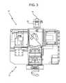
- FIG. 3is a front cross sectional view of a head portion of a laser scanner having a projector externally mounted to the head portion in accordance with embodiments of the present invention
- FIG. 4are two views showing visualization of movement over time of the Tower of Pisa using a projected image of the Tower of Pisa earlier in time utilizing the laser scanner having the projector according to the embodiments of FIGS. 1-3 ;
- FIG. 5shows a laser scanner with a projector according to embodiments of the present invention projecting “hidden features” onto a surface such as a wall;
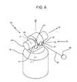
- FIG. 6is a perspective view of a laser tracker having a projector integrated therein in accordance with embodiments of the present invention.
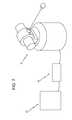
- FIG. 7is a perspective view of the laser tracker of FIG. 6 having computing and power supply elements attached thereto;
- FIG. 8is a perspective view of the laser tracker of FIG. 6 projecting a pattern onto a surface of an object or workpiece according to embodiments of the present invention
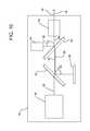
- FIG. 9is a block diagram of various components including a projector within a portion of the laser tracker of FIG. 6 according to embodiments of the present invention.
- FIG. 10is a block diagram of various components including a projector within a portion of the laser tracker of FIG. 6 according to other embodiments of the present invention.
- FIG. 11is a perspective view of alternative embodiments of the laser tracker of FIG. 6 with an external projector projecting a pattern onto a surface of an object or workpiece.
- a rotating scanning head portion 10 of a laser scanner 12having a commercially available, relatively small or “miniature,” “ultraminiature,” or “pico” projector 14 integrated directly within the optical components (“optics”) located within the scanner head 10 .
- the projector 14may contain some amount of processing capability, as is known.
- the projector 14may be connected with, or in communication with, a first computer or processor 15 of the laser scanner 12 , where the computer or processor may be integral with the scanner 12 (e.g., located within the scanner head 10 ) or may be a second separate computer or processor 17 therefrom (e.g., a laptop computer).
- the scanner head 10is typically mounted to a supporting tripod (not shown), which sits on the ground or other surface during laser scanner use.
- the projector 14sends various images, data or other information through the optics within the scanner head 10 and onto a rotating scanning mirror 16 that typically rotates relatively quickly through 360 degrees about a horizontal axis through the head 10 , wherein the mirror 16 projects the images, data or other information towards a surface (not shown) for viewing.
- the scanner head 10itself may rotate relatively more slowly through 360 degrees about a vertical axis through the head 10 .
- Various embodiments of the present inventioninclude the integration or addition of such a relatively small image or data projector into equipment generally used for 3D measurement or metrology, including but not limited to, a laser scanner, laser tracker, white light scanner or similar type technological device or instrument.
- the projectormay be integrated within the laser scanner 12 or laser tracker, and the projected images, data or other information are controlled using data or information from the measurement equipment 12 itself, data or information previously captured by the measurement equipment 12 , or data or information from some other source.
- the projected images or dataprovide visualization of various types of information that is useful during a measurement session, or the projected images or data can assist in visualization of data previously taken by the equipment 12 .
- the projected visual informationmay, for example, be of a type such as to provide guidance to an operator, such as written instructions, highlighted points to be measured, indicated areas where data are to be taken, and real time feedback on the quality of the data.
- This visual information provided to the operatormay, for example, be in the form of visual cues, text or some other visual form of information.
- the projectormay comprise one or more commercially available galvanometers or polygon scanners rather than one of the types of projectors mentioned herein above, for example, a miniature, ultraminiature, or pico-projector which might be based, for example, on microelectromechanical systems (MEMS) technology, liquid crystal display (LCD) or liquid crystal on silicon (LCOS) technology.
- MEMSmicroelectromechanical systems
- LCDliquid crystal display
- LCOSliquid crystal on silicon
- typically two galvanometers or two polygon scannersare used with associated mirrors to project the desired image, data, or information, in a desired pattern in two dimensions onto the surface of interest.
- the galvanometer mirrorsproject the images or other information onto the rotating mirror where they are reflected off of towards the object of interest.
- the laser scanner 12creates the images in the same way that images are generated for laser light shows.
- the galvanometer mirrorswould project the images or other information directly onto the target of interest.
- the size of the pattern projected by a projector disposed on the trackermay be expanded by moving the tracker head to cover a relatively large area while, at the same time, dynamically changing the pattern from the projector to produce the desired image over a relatively large region of space. This way, the head of the laser tracker acts like a galvanometer mirror.
- the galvanometers or polygon scannersmay provide a relatively more powerful, brighter and more efficient laser beam for image or data projection purposes as compared to the light from a pico projector.
- the focusing mechanismwill generally include a mechanical actuator for moving one or more lenses.
- Colormay be used advantageously in providing information about an object.
- Laser scanners and laser trackersfrequently employ optics, sensors, mirrors, and/or laser sources mounted to motors and/or gimbals such that the scanner or tracker instrument or device 12 can automatically scan a large area or object or track a movable target (e.g., a retroreflector) within the working volume of the device 12 without the need to manually aim or move the sensor modules of the device 12 .
- a movable targete.g., a retroreflector
- the laser light emitted from a laser light source 18can be directed through use of a mirror 20 .
- Techniquesare known that allow the reflective surface of a mirror 20 to be coated in such a way (e.g., “dichroic” coating) as to reflect light at the wavelength of the source laser 18 while passing light of other wavelengths.
- a miniature projector 14to be mounted behind an angled mirror 20 that reflects the laser beam emitted from the laser 18 to the rotating scanning mirror 16 ( FIG. 1 ).
- the motors, encoders and drive circuitry used to point the laser beamalso simultaneously direct the beam of the projector 14 via the scanning mirror 16 ( FIG. 1 ).
- the computer or processor associated with the laser scanner 12may be required to perform some mathematical calculations to correctly locate the image or data from the projector 14 onto the rotating scanning mirror 16 .
- These calculationsshould be apparent to one of ordinary skill in the art. That is, the projected image or data is compensated for to account for the rotation of the mirror 16 so that the image or data is not distorted or smeared.
- the image projected by the projector 14 onto the mirror 16may be changed dynamically to provide an image that is stationary on a projection surface (e.g., a wall).
- the mirror 16typically is made to rotate, in part, for laser safety reasons.
- the laser that provides the laser beam to the rotating scanning mirror 16 for metrology purposesmay be turned off, the mirror 16 may be held in a stationary position, and then the projector 14 may provide the relatively weaker light that comprises the image or data to the mirror 16 .
- no mathematical corrections for the now stationary mirror 16are typically needed.
- the size of the image projected onto the reflective surface of the mirror 16is adjusted according to the distance from the scanner to the projection surface. This would be the case, for example, if the projector were to emit a diverging pattern of light and if the image on the projection surface were intended to have a fixed size. In this case, the distance measuring capability of the scanner may provide the information needed to enable the projector 14 to correctly size the projected image.
- the image, data or other information projected from the projector 14 onto the surface of interestmay have its timing controlled such that the image, data or other information may be mechanically or electronically strobed to coincide with certain angles of the rotating scanning mirror 16 .
- the laser beam used by the scanner 12 for metrology purposesmay be provided in a mutually exclusive manner (e.g., multiplexed) with respect to the image, data or other information provided from the projector 14 . That is, the laser beam and the projected light pattern or data may not be “on” (i.e., projected) at the same time, as that condition may not be necessary. Alternatively, the laser beam and the projected light pattern may be on at the same time.
- the projecting mode of the laser scanner 12is not tied to or dependent upon the scanning mode of the scanner 12 .
- the projector 14can be mounted to multi-axis, motorized gimbals 22 , for example, on top of the laser scanner head 10 , as an alternative to being installed in-line with the measurement optics of the laser scanner 12 as in the embodiments of FIGS. 1 and 2 .
- Thisallows the projection system 14 to be added to existing laser scanner equipment 12 that may not support the full integration embodiments of FIGS. 1 and 2 .
- the embodiment of FIG. 3may in some situations be simpler and less expensive to implement.
- the gimbals 22 upon which the projector 14 is mountedmay be driven and aimed in synchronization with the optics of the 3D measurement device 12 , thus assuring that the projector image is pointed to the same area that is of interest in taking measurements by the laser scanner 12 .
- the independently mounted projector 14may be commanded to project images in an area different than the primary device optics.
- the position and orientation of a 3D metrology devicesuch as a 3D laser scanner 12 or laser tracker relative to an object, part or structure to be measured may be established by identification of reference points or part or object features using known techniques.
- both the 3D metrology device (e.g., the laser scanner) 12 and the projector 14can be synchronized and controlled with a relatively high degree of precision by an external computer connected to the device 12 as part of the device 12 , or an on-board computer as part of the device 12 that can process the device position and control the orientation of the device optics.
- Thisallows the projected image to be shaped, scaled and controlled to match the surface onto which it projected, and it allows the image to update as the direction of the projector 14 changes such that it is always synchronized and locked to the environment.
- a projector 14 integrated within, or mounted to, a computer controlled 3D measurement device such as a laser scanner 12include, but are not limited to, projecting data, text, instructions, images or guidance in the form of, for example, visual cues or text or other forms of information on the surface of a part to be measured. They may also include providing a projected overlay of previously scanned/measured data or CAD data showing design intent for visualization of changes to a part or parameters.
- thismay include: (1) comparison of a car body before and after an accident or before and after repair; (2) comparison of the CAD design of a planned equipment installation compared to the actual completed installation; (3) visualization of a proposed change to a part, equipment set-up, assembly line, wall, or building; (4) visualization of a part design compared to a drawing as a method of inspection; (5) visualization of hidden features ( FIG.
- studs, piping, electrical wiring and ductworks behind a wall, ceiling or floor by projecting CAD data of the design, or scans taken during construction, onto the visible surface; (6) visualization of elements beneath the skin of the human or animal body by projecting an image of a 3D CAT scan, 3D X-ray or other 3D diagnostic data onto the body, which can provide visual assistance in locating organs, tumors, blood vessels, bones, or other physiological features as part of a surgical procedure; (7) visualization of crime scenes, before and after; (8) projection of contour maps onto a part, thereby indicating regions of the part that need to be removed, for example, by filing, sanding, or lapping, or filled in, for example, with epoxy filler; (9) projection of marks indicating areas in which subcomponents should be attached to the object, for example, with bolts, screws, or adhesive; (10) projection of lines, curves, marks, or fiducial features for aid in aligning of components; and (11) visualization of degradation or movement over time (via
- the sole view 400 in FIG. 4A and the right hand leaning view 400 in FIG. 4shows the Tower of Pisa tilted to the right side as viewed in FIGS. 4A and 4B , and also having a upright vertical image 410 of the Tower (shown in dotted lines in FIG. 4B ) projected (in part) onto the leaning tower view 400 in FIG. 4B by the laser scanner 12 having the projector 14 , according to various embodiments of the present invention.
- multiple projectors 14may be incorporated into a single device such as a laser scanner 12 . This allows for a potential increase in the range of image coverage, ultimately to 360 degrees around the scanning device, with the possible exception of relatively small areas blocked by the laser scanner itself (e.g., at the location where the scanner head 10 attaches to the tripod).
- synchronized imagesmay be generated by multiple projectors 14 mounted independently of the laser scanner 12 or laser tracker, for example, on gimbaled computer controlled mounts or in fixed positions measured and known to the laser scanner 12 or tracker.
- each projector 14may be controlled by the laser scanner 12 or tracker, or by a computer attached to the laser scanner 12 or tracker and used to establish the coordinate system of the area.
- These embodimentsmay provide for relatively broader simultaneous coverage by the projected images while also supporting image projection in areas that might otherwise be blocked by equipment or features, including by the laser scanner 12 itself.
- Images projected by this array of projectors 14can then be managed and controlled by the central computer or laser scanner 12 or other metrology device such that the projected images or data or other information is scaled, sized and properly aligned to the objects in the environment.
- the projector 14projects images, data or other information that is related to the direction and/or orientation that the laser scanner 14 is currently pointed to.
- the movement of a person or other objectmay be tracked by the laser scanner 14 and then images or data may be projected by the laser scanner 12 with the projector 14 according to the position and/or orientation of that person or object.
- Embodiments of the present inventionmay be applied to any computer controlled aiming system that can establish a baseline coordinate system on a part or in an environment such that projected images can be aligned with the surface onto which they are projected.
- Other embodiments of the present inventionmay be utilized for entertainment purposes and may comprise, for example, projecting a movie on the surrounding walls of a room.
- a moving objecte.g., a person
- the projected images within the environmentcan be automatically adjusted as a function of, for example, the person's movement, actions, or head orientation.
- the 3D space reconstructionis different than the 2D gaming technologies.
- a systemmay have a laser scanner or tracker detect and follow a person walking around building, all the while projecting information on the wall that a person looks at.
- the projectorcannot cover 360 degrees of space, but it can selectively project where someone is looking at, which gives the perception of projection over 3D space.
- a laser scanner 12having a projector 14 according to embodiments of the present invention in which the projector 14 projects “hidden features” 24 onto a surface such as a wall 26 .
- the hidden featuresmay include objects such as, for example, studs, piping, electrical wiring and duct works that are located behind the wall 26 , ceiling, floor or other visible surface.
- a workermay not know what is exactly positioned behind the wall surface 26 and/or does not know the exact positioning of these items behind the wall surface 26 . It would be beneficial to provide the worker with an image of the items behind the wall surface 22 and the exact location of those items.
- this information about the hidden featuresis available as, e.g., CAD design data.
- the projection of hidden featuresmay come about, for example, by first scanning a building such as a home using a laser scanner 12 during various construction phases (e.g., framing, wiring, plumbing, HVAC, etc.) to obtain scanned point cloud data of various structural details of the building. After completion of certain phases of the scanning to collect images and data, the laser scanner 12 with the projector 14 may then be used to project various “real” images and/or data obtained from the scanning process onto the walls, ceiling, floors, etc. Alternatively, CAD design “intent” data of the various surfaces of the building may be projected onto the surfaces.
- various construction phasese.g., framing, wiring, plumbing, HVAC, etc.
- the projection of the hidden features onto these surfacesmay assist someone in carrying out tasks, such as, for example, drilling a hole in a precise location of a stud behind a wall.
- These embodiments of the present inventionallow a user of the laser scanner 12 with the projector 14 to identify the precise location of these objects or features such that no harm is caused to other objects or that no time is wasted trying to locate these hidden objects or features.
- the hidden featuresmay comprise those within a human body that are covered by skin.
- the projector 14may project data onto the patient's skin to assist a doctor or surgeon in precisely locating internal human body parts to be accessed and/or surgically operated on.
- a doctormay use a laser scanner 12 having a projector 14 to determine a precise location for making an incision or finding a tumor, correlating this location with 3D Computer Axial Tomography (CAT) data.
- CATComputer Axial Tomography
- the projector 14may project an image on the patient, providing markers or actual replication of CAT scan imagery to guide the surgeon. Surgery performed remotely by manually operated robots may use such projection systems 14 in the same way as described above.
- the projectormay display regions as they would appear following attachment. For example, before the wall surface 26 was in place in FIG. 5 and before the pipes and other construction elements were installed behind the wall surface 26 , a scanner could display the desired appearance of the area, thereby providing guidance to the builder.
- the laser tracker 30includes a gimbaled beam-steering mechanism 32 that comprises a zenith carriage 34 mounted on an azimuth base 36 and rotated about an azimuth axis 38 .
- a payload 40is mounted on the zenith carriage 34 and is rotated about a zenith axis 42 .
- the zenith mechanical rotation axis 42 and the azimuth mechanical rotation axis 38intersect orthogonally, internally to the tracker 30 , at a gimbal point 44 , which is typically the origin for distance measurements.
- a laser beam 46virtually passes through the gimbal point 44 and is pointed orthogonal to the zenith axis 42 .
- the laser beam 46is in the plane normal to the zenith axis 42 .
- the laser beam 46is pointed in the desired direction by motors located within the tracker 30 that rotate the payload 40 about the zenith axis 42 and the azimuth axis 38 .
- Zenith and azimuth angular encoders (not shown) or transducers 41 , 43located internal to the tracker 30 , are attached to the zenith mechanical axis 42 and to the azimuth mechanical axis 38 , and indicate, to a relatively high degree of accuracy, the angles of rotation.
- the laser beam 46travels to an external retroreflector 48 such as a spherically mounted retroreflector (SMR).
- SMRspherically mounted retroreflector
- the laser beam 46may comprise one or more laser wavelengths.
- a steering mechanism of the type shown in FIG. 6is assumed in the following discussion. However, other types of steering mechanisms are possible. For example, it may be possible to reflect a laser beam off a mirror rotated about the azimuth and zenith axes 38 , 42 . An example of the use of a mirror in this way is disclosed in U.S. Pat. No. 4,714,339 to Lau et al. The techniques described here are applicable, regardless of the type of steering mechanism utilized.
- each camera 50may comprise a photosensitive array and a lens placed in front of the photosensitive array.
- the photosensitive arraymay be a CMOS or CCD array.
- the lensmay have a relatively wide field of view, for example, thirty or forty degrees. The purpose of the lens is to form an image on the photosensitive array of objects within the field of view of the lens.
- Each light source 52is placed near a camera 50 so that light from the light source 52 is reflected off each retroreflector target 48 onto the camera 50 .
- retroreflector imagesare readily distinguished from the background on the photosensitive array as their image spots are brighter than background objects and are pulsed.
- the principle of triangulationcan be used to find the three-dimensional coordinates of any SMR 48 within the field of view of the camera 50 .
- the three-dimensional coordinates of the SMR 48can be monitored as the SMR 48 is moved from point to point.
- a use of two cameras for this purposeis described in U.S. Published Patent Application No. US20100128259 to Bridges.
- a light source 52 and a camera 50can be coaxial or nearly coaxial with the laser beams 46 emitted by the tracker 30 .
- Another possible arrangementis to use a single camera 50 located on the payload or base 40 of the tracker 30 .
- a single camera 50if located off the optical axis of the laser tracker 30 , provides information about the two angles that define the direction to the retroreflector 48 but not the distance to the retroreflector 48 . In many cases, this information may be sufficient. If the 3D coordinates of the retroreflector 48 are needed when using a single camera 50 , one possibility is to rotate the tracker 30 in the azimuth direction by 180 degrees and then to flip the zenith axis 42 to point back at the retroreflector 48 . In this way, the target 48 can be viewed from two different directions and the 3D position of the retroreflector 48 can be found using triangulation.
- Another possibilityis to switch between measuring and imaging of the target 48 .
- An example of such a methodis described in international application WO 03/062744 to Bridges et al.
- Other camera arrangementsare possible and can be used with the methods described herein.
- an auxiliary unit 60is usually a part of the laser tracker 30 .
- the purpose of the auxiliary unit 60is to supply electrical power to the laser tracker body and in some cases to also supply computing and clocking capability to the system. It is possible to eliminate the auxiliary unit 60 altogether by moving the functionality of the auxiliary unit 60 into the tracker body.
- the auxiliary unit 60is attached to a general purpose computer 62 .
- Application software loaded onto the general purpose computer 62may provide application capabilities such as reverse engineering. It is also possible to eliminate the general purpose computer 62 by building its computing capability directly into the laser tracker 30 . In this case, a user interface, preferably providing keyboard and mouse functionality is built into the laser tracker 30 .
- the connection between the auxiliary unit 60 and the computer 62may be wireless or through a cable of electrical wires.
- the computer 62may be connected to a network, and the auxiliary unit 60 may also be connected to a network.
- Plural instrumentsfor example, multiple measurement instruments or actuators, may be connected together, either through the computer 62 or the auxiliary unit 60 .
- a laser tracker 30having an internal projector 94 (not shown) integrated within the tracker 30 ( FIGS. 9-10 ) and projecting a pattern 70 onto a surface 72 of an object 74 , such as a workpiece.
- a pattern 70may be used, for example, to highlight the features 76 where measurements with the tracker 30 are to be taken through use of a circle 78 , while also overlaying indicators 80 where the measurement device 30 would acquire the measurement points.
- the componentsinclude one or more distance meters 80 , which may comprise an interferometer (IFM), an absolute distance meter (ADM), or both. Emitted from the distance meter 80 is one or more laser beams 82 , which might be visible or infrared or both.
- the outgoing laser beam 82passes through a first beam splitter 84 . If the outgoing laser beam 82 is directed to a retroreflector 48 ( FIG. 6 ), then on the return path this retroreflected laser beam 86 bounces off this first beam splitter 84 and travels to a position detector 88 .
- the position of the light on the position detector 88is used by the control system of the laser tracker 30 to keep the laser outgoing beam 82 centered on the retroreflector 48 , thereby enabling the tracking function. If the outgoing laser beam 82 is directed to the workpiece 74 ( FIG. 8 ) rather than a retroreflector 48 , then the position of the returning laser beam 86 on the position detector 88 is not important. After passing through the first beam splitter 84 , the outgoing laser beam 82 passes through a beam expander 90 , which causes the diameter of the outgoing laser beam 82 to increase when the beam is traveling in the forward direction (out toward the retroreflector 48 ). The outgoing laser beam 82 then passes though a second beam splitter 92 .
- Light from a projector 94(similar to the projector 14 in the embodiments of FIGS. 1-5 ) sends a pattern of laser light 96 onto the second beam splitter 92 .
- the reflected light 96 off of the second beam splitter 92combines with the outgoing laser beam 82 from the distance meters 80 , and the combined light 98 travels to either the retroreflector 48 or to the workpiece 74 .
- the laser beam 98is directed toward the workpiece 74 , it may be possible to turn off the any visible light contained within the beam 82 . This may allow the projected beam 98 to be more clearly seen.
- FIG. 10there illustrated is an embodiment of the various components of the laser tracker 30 similar to that of FIG. 9 , except that the second beam splitter 92 and the projector 94 are both placed in front of the beam expander 90 .
- the advantage of this approachis that the second beam splitter 92 can be made smaller than for the embodiment of FIG. 9 .
- the disadvantageis that it may be more difficult to obtain proper alignment of the projector 94 .
- the laser tracker 30has the projector 94 integrated within the internal components of the laser tracker 30 .
- the projector 94it is possible for the projector 94 to be mounted on or otherwise attached to the laser tracker 30 .
- FIG. 11illustrates such an embodiment in which the laser tracker 30 has the projector 14 mounted on top of the tracker body.
- the projector 14may be mounted rigidly to the tracker body or the projector 14 may be mounted using a gimbal mechanism 22 similar to that of the embodiment of the laser scanner 12 shown in FIG. 3 .
- the projectoris offset from the optical axis that carries the laser beams 82 and 86 .
- the optical system that carries the light beam 82may be made more compact and the distance from the projector to the region outside the tracker made smaller, thereby enabling creation of two-dimensional patterns having larger divergence angles.
- the projector 94may project images, data or other information.
- Such projected informationprovides visualization to an operator of various types of information that is useful during a measurement session using the laser tracker 30 , or the projected images or data can assist in visualization of data previously taken by the equipment 12 .
- the projected visual informationmay, for example, be of a type such as to provide guidance to an operator, such as written instructions, highlighted points to be measured, indicated areas where data are to be taken, and real time feedback on the quality of the data.
- This visual information provided to the operatormay, for example, be in the form of visual cues, text or some other visual form of information.
- the uses to which the projected images may be putare generally the same as for a laser scanner.
- laser trackersare (1) projections in which marks indicate where material is to be removed from or added to a structure and (2) projections in which marks indicate where components are to be added to a structure.
Landscapes
- Engineering & Computer Science (AREA)
- Physics & Mathematics (AREA)
- General Physics & Mathematics (AREA)
- Radar, Positioning & Navigation (AREA)
- Remote Sensing (AREA)
- Computer Networks & Wireless Communication (AREA)
- Electromagnetism (AREA)
- Length Measuring Devices By Optical Means (AREA)
- Optical Radar Systems And Details Thereof (AREA)
Abstract
Description
This application claims priority to U.S. Provisional Application No. 61/380,869, filed on Sep. 8, 2010; and to U.S. Non-Provisional application Ser. No. 13/006,507, filed on Jan. 14, 2011; which claims the benefit of priority to U.S. Provisional Application No. 61/296,555 filed on Jan. 20, 2010, to U.S. Provisional Application No. 61/351,347 filed on Jun. 4, 2010 and to U.S. Provisional Application No. 61/355,279 filed on Jun. 16, 2010. The present application also claims priority to U.S. Non-Provisional application Ser. No. 13/006,468, filed on Jan. 14, 2011; which claims the benefit of priority to U.S. Provisional Application No. 61/296,555 filed on Jan. 20, 2010, to U.S. Provisional Application No. 61/351,347 filed on Jun. 4, 2010 and to U.S. Provisional Application No. 61/355,279 filed on Jun. 16, 2010. The present application also claims priority to U.S. Non-Provisional application Ser. No. 13/006,524, filed on Jan. 14, 2011; which claims the benefit of priority to U.S. Provisional Application No. 61/296,555, filed on Jan. 20, 2012; the entire contents of each which are incorporated herein by reference.
The present invention relates to coordinate measurement devices, for example, laser scanners, laser trackers, and total stations, and more particularly to laser scanners and laser trackers having one or more relatively small projectors integrated therewith or added thereto by, e.g., mounting thereon, for projecting visual information in the form of images and/or data (e.g., CAD data or scanned point cloud data) onto various surfaces. The projected visual information may, for example, be of a type such as to provide guidance to an operator, such as written instructions, highlighted points to be measured, indicated areas where data are to be taken, and real time feedback on the quality of the data.
A laser scanner is one type of coordinate measurement device typically used for non-contact optical scanning of many different types of relatively large closed or open spaces or objects, for example, interior spaces of buildings, industrial installations and tunnels, or exterior shapes of planes, automobiles or boats. Laser scanners can be used for many different purposes, including industrial applications and accident reconstruction. A laser scanner optically scans and measures the environment around the laser scanner by emitting a rotating laser beam and detecting the laser beam as it is reflected back from the various objects in its path. Laser scanners typically collect a variety of data points with respect to the environment, including distance information for each object in its surrounding environment, a grey scale value (i.e., a measure of the intensity of light) for each distance measurement value, and coordinates (e.g., x, y, and z) for each distance measurement value. This scan data is collected, stored and sent to a processor that is typically remote from the laser scanner, where the data is processed to generate a three dimensional (3D) scanned image of the scanned environment with measurements. In order to generate the 3D scanned image, at least four values (x, y, z coordinates and grey scale value) are collected for each scanned data point.
Many contemporary laser scanners also include a camera mounted on the laser scanner for gathering digital images of the environment and for presenting the digital images to an operator of the laser scanner. The images can be oriented together with the scanned data to provide a more realistic image of the object being scanned. By viewing the images, the operator of the scanner can determine the field of view of the scanned data, and can adjust the settings on the laser scanner if the field of view needs adjusting. In addition, the digital images may be transmitted to the processor to add color to the 3D scanned image. In order to generate a 3D color scanned image, at least six values (x, y, z coordinates; and red value, green value, blue value or “RGB”) are collected for each data point. Examples of laser scanners are disclosed in U.S. Pat. No. 7,193,690 to Ossig et al.; U.S. Pat. No. 7,430,068 to Becker et al.; and U.S. Published Patent Application No. US2010/0134596 to Becker; each being incorporated by reference herein.
Another type of coordinate measurement device is a laser tracker, which measures the 3D coordinates of a certain point by sending a laser beam to the point, where the laser beam is typically intercepted by a retroreflector target. The laser tracker finds the coordinates of the point by measuring the distance and the two angles to the target. The distance is measured with a distance-measuring device such as an absolute distance meter (ADM) or an interferometer. The angles are measured with an angle-measuring device such as an angular encoder. A gimbaled beam-steering mechanism within the instrument directs the laser beam to the point of interest. The retroreflector may be moved manually by hand, or automatically, over the surface of the object. The laser tracker follows the movement of the retroreflector to measure the coordinates of the object. Exemplary laser trackers are disclosed in U.S. Pat. No. 4,790,651 to Brown et al., incorporated by reference herein; and U.S. Pat. No. 4,714,339 to Lau et al. The total station, which is most often used in surveying applications, may be used to measure the coordinates of diffusely scattering or retroreflective targets. The total station is closely related to both the laser tracker and the scanner.
A common type of retroreflector target is the spherically mounted retroreflector (SMR), which comprises a cube-corner retroreflector embedded within a metal sphere. The cube-corner retroreflector comprises three mutually perpendicular mirrors. The apex of the cube corner, which is the common point of intersection of the three mirrors, is located at the center of the sphere. It is common practice to place the spherical surface of the SMR in contact with an object under test and then move the SMR over the surface of the object being measured. Because of this placement of the cube corner within the sphere, the perpendicular distance from the apex of the cube corner to the surface of the object under test remains constant despite rotation of the SMR. Consequently, the 3D coordinates of the object's surface can be found by having a tracker follow the 3D coordinates of an SMR moved over the surface. It is possible to place a glass window on the top of the SMR to prevent dust or dirt from contaminating the glass surfaces. An example of such a glass surface is shown in U.S. Pat. No. 7,388,654 to Raab et al., incorporated by reference herein.
A gimbal mechanism within the laser tracker may be used to direct a laser beam from the tracker to the SMR. Part of the light retroreflected by the SMR enters the laser tracker and passes onto a position detector. The position of the light that hits the position detector is used by a tracker control system to adjust the rotation angles of the mechanical azimuth and zenith axes of the laser tracker to keep the laser beam centered on the SMR. In this way, the tracker is able to follow (track) the SMR as it is moved.
Angular encoders attached to the mechanical azimuth and zenith axes of the tracker may measure the azimuth and zenith angles of the laser beam (with respect to the tracker frame of reference). The one distance measurement and two angle measurements performed by the laser tracker are sufficient to completely specify the three-dimensional location of the SMR.
As mentioned, two types of distance meters may be found in laser trackers: interferometers and absolute distance meters (ADMs). In the laser tracker, an interferometer (if present) may determine the distance from a starting point to a finishing point by counting the number of increments of known length (usually the half-wavelength of the laser light) that pass as a retroreflector target is moved between the two points. If the beam is broken during the measurement, the number of counts cannot be accurately known, causing the distance information to be lost. By comparison, the ADM in a laser tracker determines the absolute distance to a retroreflector target without regard to beam breaks, which also allows switching between targets. Because of this, the ADM is said to be capable of “point-and-shoot” measurement. Initially, absolute distance meters were only able to measure stationary targets and for this reason were always used together with an interferometer. However, some modern absolute distance meters can make rapid measurements, thereby eliminating the need for an interferometer. Such an ADM is described in U.S. Pat. No. 7,352,446 to Bridges et al., incorporated by reference herein. The distances measured by interferometers and absolute distance meters are dependent on the speed of light through air. Since the speed of light varies with air temperature, barometric pressure, and air humidity, it is common practice to measure these quantities with sensors and to correct the speed of light in air to obtain more accurate distance readings. The distances measured by total stations and scanners also depend on the speed of light in air.
In its tracking mode, the laser tracker automatically follows movements of the SMR when the SMR is in the capture range of the tracker. If the laser beam is broken, tracking will stop. The beam may be broken by any of several means: (1) an obstruction between the instrument and SMR; (2) rapid movements of the SMR that are too fast for the instrument to follow; or (3) the direction of the SMR being turned beyond the acceptance angle of the SMR. By default, following the beam break, the beam may remain fixed at the point of the beam break, at the last commanded position, or may go to a reference (“home”) position. It may be necessary for an operator to visually search for the tracking beam and place the SMR in the beam in order to lock the instrument onto the SMR and continue tracking.
Some laser trackers include one or more cameras. A camera axis may be coaxial with the measurement beam or offset from the measurement beam by a fixed distance or angle. A camera may be used to provide a wide field of view to locate retroreflectors. A modulated light source placed near the camera optical axis may illuminate retroreflectors, thereby making them easier to identify. In this case, the retroreflectors flash in phase with the illumination, whereas background objects do not. One application for such a camera is to detect multiple retroreflectors in the field of view and measure each retroreflector in an automated sequence. Exemplary systems are described in U.S. Pat. No. 6,166,809 to Pettersen et al., and U.S. Pat. No. 7,800,758 to Bridges et al., incorporated by reference herein.
Some laser trackers have the ability to measure with six degrees of freedom (DOF), which may include three coordinates, such as x, y, and z, and three rotations, such as pitch, roll, and yaw. Several systems based on laser trackers are available or have been proposed for measuring six degrees of freedom. Exemplary systems are described in U.S. Pat. No. 7,800,758 to Bridges et al., U.S. Pat. No. 5,973,788 to Pettersen et al., and U.S. Pat. No. 7,230,689 to Lau.
It is desirable to provide a laser scanner or a laser tracker with one or more projectors, with each projector projecting visual information in the form of images and/or data (e.g., CAD data or scanned point cloud data) onto various surfaces. The projected visual information may, for example, be of a type such as to provide guidance to an operator, such as written instructions, highlighted points to be measured, indicated areas where data are to be taken, and real time feedback on the quality of the data.
According to an aspect of the present invention, a laser scanner includes a light source that emits a light beam within an environment, and a data capture component that captures the light beam reflected back to the laser scanner from the environment. The laser scanner also includes a projector integrated within a body of the laser scanner or mounted to the body of the laser scanner at a predetermined location, the projector being operable to project visible information onto an object located within the environment, the projected visible information being indicative of images, data or information, the projected visible information being at least one of design intent information, information acquired by the laser scanner, or guidance to an operator.
According to another aspect of the present invention, a laser tracker includes a light source that emits a light beam towards a target located within an environment, and a data capture component that captures the light beam reflected back to the laser scanner from the target located within the environment. The laser tracker also includes a projector integrated within a body of the laser tracker or mounted to the body of the laser tracker at a predetermined location, the projector being operable to project visible information onto an object located within the environment, the projected visible information being indicative of images, data or information, the projected visible information being at least one of design intent information, information acquired by the laser tracker, or guidance to an operator.
Referring now to the drawings, exemplary embodiments are shown which should not be construed to be limiting regarding the entire scope of the disclosure, and wherein the elements are numbered alike in several FIGURES:
Referring toFIG. 1 , in accordance with embodiments of the present invention, there illustrated is a rotatingscanning head portion 10 of alaser scanner 12 having a commercially available, relatively small or “miniature,” “ultraminiature,” or “pico”projector 14 integrated directly within the optical components (“optics”) located within thescanner head 10. Theprojector 14 may contain some amount of processing capability, as is known. Theprojector 14 may be connected with, or in communication with, a first computer orprocessor 15 of thelaser scanner 12, where the computer or processor may be integral with the scanner12 (e.g., located within the scanner head10) or may be a second separate computer orprocessor 17 therefrom (e.g., a laptop computer). Thescanner head 10 is typically mounted to a supporting tripod (not shown), which sits on the ground or other surface during laser scanner use. As described in more detail with respect toFIG. 2 , theprojector 14 sends various images, data or other information through the optics within thescanner head 10 and onto arotating scanning mirror 16 that typically rotates relatively quickly through 360 degrees about a horizontal axis through thehead 10, wherein themirror 16 projects the images, data or other information towards a surface (not shown) for viewing. Thescanner head 10 itself may rotate relatively more slowly through 360 degrees about a vertical axis through thehead 10.
Various embodiments of the present invention include the integration or addition of such a relatively small image or data projector into equipment generally used for 3D measurement or metrology, including but not limited to, a laser scanner, laser tracker, white light scanner or similar type technological device or instrument. In embodiments of the present invention, the projector may be integrated within thelaser scanner 12 or laser tracker, and the projected images, data or other information are controlled using data or information from themeasurement equipment 12 itself, data or information previously captured by themeasurement equipment 12, or data or information from some other source. As described in detail hereinafter, the projected images or data provide visualization of various types of information that is useful during a measurement session, or the projected images or data can assist in visualization of data previously taken by theequipment 12. The projected visual information may, for example, be of a type such as to provide guidance to an operator, such as written instructions, highlighted points to be measured, indicated areas where data are to be taken, and real time feedback on the quality of the data. This visual information provided to the operator may, for example, be in the form of visual cues, text or some other visual form of information.
Further, the projector may comprise one or more commercially available galvanometers or polygon scanners rather than one of the types of projectors mentioned herein above, for example, a miniature, ultraminiature, or pico-projector which might be based, for example, on microelectromechanical systems (MEMS) technology, liquid crystal display (LCD) or liquid crystal on silicon (LCOS) technology. For example, typically two galvanometers or two polygon scanners are used with associated mirrors to project the desired image, data, or information, in a desired pattern in two dimensions onto the surface of interest. In the case of alaser scanner 12, the galvanometer mirrors project the images or other information onto the rotating mirror where they are reflected off of towards the object of interest. The rotation of the main mirror in thelaser scanner 12 and the rotation of the galvanometer mirror also in thelaser scanner 12 creating the image or other projected information would be synchronized. As such, the laser scanner creates the images in the same way that images are generated for laser light shows. In the case of a laser tracker (discussed in more detail hereinafter), the galvanometer mirrors would project the images or other information directly onto the target of interest. The size of the pattern projected by a projector disposed on the tracker may be expanded by moving the tracker head to cover a relatively large area while, at the same time, dynamically changing the pattern from the projector to produce the desired image over a relatively large region of space. This way, the head of the laser tracker acts like a galvanometer mirror. When used, the galvanometers or polygon scanners may provide a relatively more powerful, brighter and more efficient laser beam for image or data projection purposes as compared to the light from a pico projector.
In many cases, it is advantageous to provide a focusing mechanism to make the projected image as sharp as possible on the surface of the object to which the two-dimensional pattern is projected. The focusing mechanism will generally include a mechanical actuator for moving one or more lenses.
With MEMS, LCD, LCOS, and other types of pico-projectors, it is common today to provide color projection patterns. Color may be used advantageously in providing information about an object.
Laser scanners and laser trackers frequently employ optics, sensors, mirrors, and/or laser sources mounted to motors and/or gimbals such that the scanner or tracker instrument ordevice 12 can automatically scan a large area or object or track a movable target (e.g., a retroreflector) within the working volume of thedevice 12 without the need to manually aim or move the sensor modules of thedevice 12.
Referring toFIG. 2 , in some embodiments of alaser scanner 10, the laser light emitted from alaser light source 18 can be directed through use of amirror 20. Techniques are known that allow the reflective surface of amirror 20 to be coated in such a way (e.g., “dichroic” coating) as to reflect light at the wavelength of thesource laser 18 while passing light of other wavelengths. Such embodiments allow aminiature projector 14 to be mounted behind anangled mirror 20 that reflects the laser beam emitted from thelaser 18 to the rotating scanning mirror16 (FIG. 1 ). In the embodiment shown inFIG. 2 , the motors, encoders and drive circuitry used to point the laser beam also simultaneously direct the beam of theprojector 14 via the scanning mirror16 (FIG. 1 ).
Thus, in some embodiments, the computer or processor associated with thelaser scanner 12 may be required to perform some mathematical calculations to correctly locate the image or data from theprojector 14 onto therotating scanning mirror 16. These calculations should be apparent to one of ordinary skill in the art. That is, the projected image or data is compensated for to account for the rotation of themirror 16 so that the image or data is not distorted or smeared. For example, the image projected by theprojector 14 onto themirror 16 may be changed dynamically to provide an image that is stationary on a projection surface (e.g., a wall). Themirror 16 typically is made to rotate, in part, for laser safety reasons. In alternative embodiments, the laser that provides the laser beam to therotating scanning mirror 16 for metrology purposes may be turned off, themirror 16 may be held in a stationary position, and then theprojector 14 may provide the relatively weaker light that comprises the image or data to themirror 16. In these embodiments, no mathematical corrections for the nowstationary mirror 16 are typically needed. In some cases, the size of the image projected onto the reflective surface of themirror 16 is adjusted according to the distance from the scanner to the projection surface. This would be the case, for example, if the projector were to emit a diverging pattern of light and if the image on the projection surface were intended to have a fixed size. In this case, the distance measuring capability of the scanner may provide the information needed to enable theprojector 14 to correctly size the projected image.
The image, data or other information projected from theprojector 14 onto the surface of interest may have its timing controlled such that the image, data or other information may be mechanically or electronically strobed to coincide with certain angles of therotating scanning mirror 16. Also, the laser beam used by thescanner 12 for metrology purposes may be provided in a mutually exclusive manner (e.g., multiplexed) with respect to the image, data or other information provided from theprojector 14. That is, the laser beam and the projected light pattern or data may not be “on” (i.e., projected) at the same time, as that condition may not be necessary. Alternatively, the laser beam and the projected light pattern may be on at the same time. Typically, the projecting mode of thelaser scanner 12, according to embodiments of the present invention, is not tied to or dependent upon the scanning mode of thescanner 12.
Referring toFIG. 3 , in other embodiments of the present invention, theprojector 14 can be mounted to multi-axis, motorized gimbals22, for example, on top of thelaser scanner head 10, as an alternative to being installed in-line with the measurement optics of thelaser scanner 12 as in the embodiments ofFIGS. 1 and 2 . This allows theprojection system 14 to be added to existinglaser scanner equipment 12 that may not support the full integration embodiments ofFIGS. 1 and 2 . The embodiment ofFIG. 3 may in some situations be simpler and less expensive to implement. In such an embodiment, the gimbals22 upon which theprojector 14 is mounted may be driven and aimed in synchronization with the optics of the3D measurement device 12, thus assuring that the projector image is pointed to the same area that is of interest in taking measurements by thelaser scanner 12. This has advantages when using theprojector 12 for guidance or data presentation. Alternately, the independently mountedprojector 14 may be commanded to project images in an area different than the primary device optics.
The position and orientation of a 3D metrology device such as a3D laser scanner 12 or laser tracker relative to an object, part or structure to be measured may be established by identification of reference points or part or object features using known techniques. Once the coordinate system has been established, both the 3D metrology device (e.g., the laser scanner)12 and theprojector 14 can be synchronized and controlled with a relatively high degree of precision by an external computer connected to thedevice 12 as part of thedevice 12, or an on-board computer as part of thedevice 12 that can process the device position and control the orientation of the device optics. This allows the projected image to be shaped, scaled and controlled to match the surface onto which it projected, and it allows the image to update as the direction of theprojector 14 changes such that it is always synchronized and locked to the environment.
Various implementations or usages of aprojector 14 integrated within, or mounted to, a computer controlled 3D measurement device such as alaser scanner 12 according to embodiments of the present invention include, but are not limited to, projecting data, text, instructions, images or guidance in the form of, for example, visual cues or text or other forms of information on the surface of a part to be measured. They may also include providing a projected overlay of previously scanned/measured data or CAD data showing design intent for visualization of changes to a part or parameters. For 3D scanned data this may include: (1) comparison of a car body before and after an accident or before and after repair; (2) comparison of the CAD design of a planned equipment installation compared to the actual completed installation; (3) visualization of a proposed change to a part, equipment set-up, assembly line, wall, or building; (4) visualization of a part design compared to a drawing as a method of inspection; (5) visualization of hidden features (FIG. 5 ) such as studs, piping, electrical wiring and duct works behind a wall, ceiling or floor by projecting CAD data of the design, or scans taken during construction, onto the visible surface; (6) visualization of elements beneath the skin of the human or animal body by projecting an image of a 3D CAT scan, 3D X-ray or other 3D diagnostic data onto the body, which can provide visual assistance in locating organs, tumors, blood vessels, bones, or other physiological features as part of a surgical procedure; (7) visualization of crime scenes, before and after; (8) projection of contour maps onto a part, thereby indicating regions of the part that need to be removed, for example, by filing, sanding, or lapping, or filled in, for example, with epoxy filler; (9) projection of marks indicating areas in which subcomponents should be attached to the object, for example, with bolts, screws, or adhesive; (10) projection of lines, curves, marks, or fiducial features for aid in aligning of components; and (11) visualization of degradation or movement over time (via sequential scans) of archaeological sites, historic buildings, bridges, railways, roads, and other facilities that are subject to wear, settling, decomposition, weathering, or general deterioration over time, as illustrated, for example, inFIG. 4 , which can be extended to the examination and visualization of wear and damage to large vehicles like ships, aircraft, spacecraft (e.g. space shuttle tiles). Specifically, thesole view 400 inFIG. 4A and the righthand leaning view 400 inFIG. 4 shows the Tower of Pisa tilted to the right side as viewed inFIGS. 4A and 4B , and also having a uprightvertical image 410 of the Tower (shown in dotted lines inFIG. 4B ) projected (in part) onto the leaningtower view 400 inFIG. 4B by thelaser scanner 12 having theprojector 14, according to various embodiments of the present invention. This illustrates the amount of movement or “tilt” to the right of the Tower of Pisa over time. Note that normally one would not see the left-hand (dotted line) portion of the uprightvertical image 410 of the Tower since it would not be projected onto the tilted Tower nor would be projected onto any other surface. That is, this dotted line left-hand portion of the uprightvertical image 410 of the Tower would be projected in free space. Instead, one would normally only see the shaded or filled in right-hand portion of the uprightvertical image 410 projected onto theTower 400. InFIG. 4B the entire uprightvertical image 410 of the Tower is shown for exemplary purposes only.
To further extend the usefulness of the controlled projected image,multiple projectors 14 may be incorporated into a single device such as alaser scanner 12. This allows for a potential increase in the range of image coverage, ultimately to 360 degrees around the scanning device, with the possible exception of relatively small areas blocked by the laser scanner itself (e.g., at the location where thescanner head 10 attaches to the tripod).
In other embodiments of the present invention, synchronized images may be generated bymultiple projectors 14 mounted independently of thelaser scanner 12 or laser tracker, for example, on gimbaled computer controlled mounts or in fixed positions measured and known to thelaser scanner 12 or tracker. In these embodiments, eachprojector 14 may be controlled by thelaser scanner 12 or tracker, or by a computer attached to thelaser scanner 12 or tracker and used to establish the coordinate system of the area. These embodiments may provide for relatively broader simultaneous coverage by the projected images while also supporting image projection in areas that might otherwise be blocked by equipment or features, including by thelaser scanner 12 itself. Images projected by this array ofprojectors 14 can then be managed and controlled by the central computer orlaser scanner 12 or other metrology device such that the projected images or data or other information is scaled, sized and properly aligned to the objects in the environment. For example, theprojector 14 projects images, data or other information that is related to the direction and/or orientation that thelaser scanner 14 is currently pointed to. As an example, the movement of a person or other object may be tracked by thelaser scanner 14 and then images or data may be projected by thelaser scanner 12 with theprojector 14 according to the position and/or orientation of that person or object.
Embodiments of the present invention may be applied to any computer controlled aiming system that can establish a baseline coordinate system on a part or in an environment such that projected images can be aligned with the surface onto which they are projected. Other embodiments of the present invention may be utilized for entertainment purposes and may comprise, for example, projecting a movie on the surrounding walls of a room. For example, if a moving object (e.g., a person) can be tracked within a stationary environment, then the projected images within the environment can be automatically adjusted as a function of, for example, the person's movement, actions, or head orientation. This involves console gaming and virtual reality technologies. However, the 3D space reconstruction is different than the 2D gaming technologies. As an example, a system may have a laser scanner or tracker detect and follow a person walking around building, all the while projecting information on the wall that a person looks at. The projector cannot cover 360 degrees of space, but it can selectively project where someone is looking at, which gives the perception of projection over 3D space.
Referring toFIG. 5 , there illustrated is alaser scanner 12 having aprojector 14 according to embodiments of the present invention in which theprojector 14 projects “hidden features”24 onto a surface such as awall 26. The hidden features may include objects such as, for example, studs, piping, electrical wiring and duct works that are located behind thewall 26, ceiling, floor or other visible surface. A worker may not know what is exactly positioned behind thewall surface 26 and/or does not know the exact positioning of these items behind thewall surface 26. It would be beneficial to provide the worker with an image of the items behind the wall surface22 and the exact location of those items. Generally, this information about the hidden features is available as, e.g., CAD design data.
The projection of hidden features according to embodiments of the present invention may come about, for example, by first scanning a building such as a home using alaser scanner 12 during various construction phases (e.g., framing, wiring, plumbing, HVAC, etc.) to obtain scanned point cloud data of various structural details of the building. After completion of certain phases of the scanning to collect images and data, thelaser scanner 12 with theprojector 14 may then be used to project various “real” images and/or data obtained from the scanning process onto the walls, ceiling, floors, etc. Alternatively, CAD design “intent” data of the various surfaces of the building may be projected onto the surfaces. Regardless of whether real or intended images and/or data are projected, the projection of the hidden features onto these surfaces may assist someone in carrying out tasks, such as, for example, drilling a hole in a precise location of a stud behind a wall. These embodiments of the present invention allow a user of thelaser scanner 12 with theprojector 14 to identify the precise location of these objects or features such that no harm is caused to other objects or that no time is wasted trying to locate these hidden objects or features.
Similar to the embodiments illustrated inFIG. 5 , the hidden features may comprise those within a human body that are covered by skin. For example, theprojector 14 may project data onto the patient's skin to assist a doctor or surgeon in precisely locating internal human body parts to be accessed and/or surgically operated on. In an operating room, for example, a doctor may use alaser scanner 12 having aprojector 14 to determine a precise location for making an incision or finding a tumor, correlating this location with 3D Computer Axial Tomography (CAT) data. In this case, theprojector 14 may project an image on the patient, providing markers or actual replication of CAT scan imagery to guide the surgeon. Surgery performed remotely by manually operated robots may usesuch projection systems 14 in the same way as described above.
Besides displaying hidden components, for example, in a construction area or in an engineering device, the projector may display regions as they would appear following attachment. For example, before thewall surface 26 was in place inFIG. 5 and before the pipes and other construction elements were installed behind thewall surface 26, a scanner could display the desired appearance of the area, thereby providing guidance to the builder.
Referring now toFIGS. 6-11 , there illustrated are embodiments of alaser tracker 30 having a projector integrated therein or mounted thereto, according to another aspect of the present invention. InFIG. 6 , thelaser tracker 30 includes a gimbaled beam-steering mechanism 32 that comprises azenith carriage 34 mounted on anazimuth base 36 and rotated about anazimuth axis 38. Apayload 40 is mounted on thezenith carriage 34 and is rotated about azenith axis 42. The zenithmechanical rotation axis 42 and the azimuthmechanical rotation axis 38 intersect orthogonally, internally to thetracker 30, at agimbal point 44, which is typically the origin for distance measurements. Alaser beam 46 virtually passes through thegimbal point 44 and is pointed orthogonal to thezenith axis 42. In other words, thelaser beam 46 is in the plane normal to thezenith axis 42. Thelaser beam 46 is pointed in the desired direction by motors located within thetracker 30 that rotate thepayload 40 about thezenith axis 42 and theazimuth axis 38. Zenith and azimuth angular encoders (not shown) ortransducers tracker 30, are attached to the zenithmechanical axis 42 and to the azimuthmechanical axis 38, and indicate, to a relatively high degree of accuracy, the angles of rotation. Thelaser beam 46 travels to anexternal retroreflector 48 such as a spherically mounted retroreflector (SMR). By measuring the radial distance between thegimbal point 44 and the retroreflector48 and the rotation angles about the zenith and azimuth axes42,38, the position of theretroreflector 48 is found within the spherical coordinate system of thetracker 30.
Thelaser beam 46 may comprise one or more laser wavelengths. For the sake of clarity and simplicity, a steering mechanism of the type shown inFIG. 6 is assumed in the following discussion. However, other types of steering mechanisms are possible. For example, it may be possible to reflect a laser beam off a mirror rotated about the azimuth and zenith axes38,42. An example of the use of a mirror in this way is disclosed in U.S. Pat. No. 4,714,339 to Lau et al. The techniques described here are applicable, regardless of the type of steering mechanism utilized.
In thelaser tracker 30, one ormore cameras 50 andlight sources 52 are located on thepayload 40. Thelight sources 52 illuminate the one or more retroreflector targets48. Thelight sources 52 may be LEDs electrically driven to repetitively emit pulsed light. Eachcamera 50 may comprise a photosensitive array and a lens placed in front of the photosensitive array. The photosensitive array may be a CMOS or CCD array. The lens may have a relatively wide field of view, for example, thirty or forty degrees. The purpose of the lens is to form an image on the photosensitive array of objects within the field of view of the lens. Eachlight source 52 is placed near acamera 50 so that light from thelight source 52 is reflected off eachretroreflector target 48 onto thecamera 50. In this way, retroreflector images are readily distinguished from the background on the photosensitive array as their image spots are brighter than background objects and are pulsed. In an embodiment, there are twocameras 50 and twolight sources 52 placed symmetrically about the line of thelaser beam 46. By using twocameras 50 in this way, the principle of triangulation can be used to find the three-dimensional coordinates of anySMR 48 within the field of view of thecamera 50. In addition, the three-dimensional coordinates of theSMR 48 can be monitored as theSMR 48 is moved from point to point. A use of two cameras for this purpose is described in U.S. Published Patent Application No. US20100128259 to Bridges.
Other arrangements of one ormore cameras 50 andlight sources 52 are possible. For example, alight source 52 and acamera 50 can be coaxial or nearly coaxial with thelaser beams 46 emitted by thetracker 30. In this case, it may be necessary to use optical filtering or similar methods to avoid saturating the photosensitive array of thecamera 50 with thelaser beam 46 from thetracker 30.
Another possible arrangement is to use asingle camera 50 located on the payload orbase 40 of thetracker 30. Asingle camera 50, if located off the optical axis of thelaser tracker 30, provides information about the two angles that define the direction to theretroreflector 48 but not the distance to theretroreflector 48. In many cases, this information may be sufficient. If the 3D coordinates of theretroreflector 48 are needed when using asingle camera 50, one possibility is to rotate thetracker 30 in the azimuth direction by 180 degrees and then to flip thezenith axis 42 to point back at theretroreflector 48. In this way, thetarget 48 can be viewed from two different directions and the 3D position of theretroreflector 48 can be found using triangulation.
Another possibility is to switch between measuring and imaging of thetarget 48. An example of such a method is described in international application WO 03/062744 to Bridges et al. Other camera arrangements are possible and can be used with the methods described herein.
As shown inFIG. 7 , anauxiliary unit 60 is usually a part of thelaser tracker 30. The purpose of theauxiliary unit 60 is to supply electrical power to the laser tracker body and in some cases to also supply computing and clocking capability to the system. It is possible to eliminate theauxiliary unit 60 altogether by moving the functionality of theauxiliary unit 60 into the tracker body. In most cases, theauxiliary unit 60 is attached to ageneral purpose computer 62. Application software loaded onto thegeneral purpose computer 62 may provide application capabilities such as reverse engineering. It is also possible to eliminate thegeneral purpose computer 62 by building its computing capability directly into thelaser tracker 30. In this case, a user interface, preferably providing keyboard and mouse functionality is built into thelaser tracker 30. The connection between theauxiliary unit 60 and thecomputer 62 may be wireless or through a cable of electrical wires. Thecomputer 62 may be connected to a network, and theauxiliary unit 60 may also be connected to a network. Plural instruments, for example, multiple measurement instruments or actuators, may be connected together, either through thecomputer 62 or theauxiliary unit 60.
Referring toFIG. 8 , there illustrated is alaser tracker 30 having an internal projector94 (not shown) integrated within the tracker30 (FIGS. 9-10 ) and projecting apattern 70 onto asurface 72 of anobject 74, such as a workpiece. Such apattern 70 may be used, for example, to highlight thefeatures 76 where measurements with thetracker 30 are to be taken through use of acircle 78, while also overlayingindicators 80 where themeasurement device 30 would acquire the measurement points.
Referring toFIG. 9 , there illustrated are various internal components within thelaser tracker 30 ofFIG. 6 . The components include one ormore distance meters 80, which may comprise an interferometer (IFM), an absolute distance meter (ADM), or both. Emitted from thedistance meter 80 is one ormore laser beams 82, which might be visible or infrared or both. Theoutgoing laser beam 82 passes through afirst beam splitter 84. If theoutgoing laser beam 82 is directed to a retroreflector48 (FIG. 6 ), then on the return path thisretroreflected laser beam 86 bounces off thisfirst beam splitter 84 and travels to aposition detector 88. The position of the light on theposition detector 88 is used by the control system of thelaser tracker 30 to keep the laseroutgoing beam 82 centered on theretroreflector 48, thereby enabling the tracking function. If theoutgoing laser beam 82 is directed to the workpiece74 (FIG. 8 ) rather than aretroreflector 48, then the position of the returninglaser beam 86 on theposition detector 88 is not important. After passing through thefirst beam splitter 84, theoutgoing laser beam 82 passes through abeam expander 90, which causes the diameter of theoutgoing laser beam 82 to increase when the beam is traveling in the forward direction (out toward the retroreflector48). Theoutgoing laser beam 82 then passes though asecond beam splitter 92. Light from a projector94 (similar to theprojector 14 in the embodiments ofFIGS. 1-5 ) sends a pattern oflaser light 96 onto thesecond beam splitter 92. The reflected light96 off of thesecond beam splitter 92 combines with theoutgoing laser beam 82 from thedistance meters 80, and the combined light98 travels to either theretroreflector 48 or to theworkpiece 74. In the case where thelaser beam 98 is directed toward theworkpiece 74, it may be possible to turn off the any visible light contained within thebeam 82. This may allow the projectedbeam 98 to be more clearly seen.
Referring toFIG. 10 , there illustrated is an embodiment of the various components of thelaser tracker 30 similar to that ofFIG. 9 , except that thesecond beam splitter 92 and theprojector 94 are both placed in front of thebeam expander 90. The advantage of this approach is that thesecond beam splitter 92 can be made smaller than for the embodiment ofFIG. 9 . The disadvantage is that it may be more difficult to obtain proper alignment of theprojector 94.
In the embodiments illustrated inFIGS. 6-10 and described herein, thelaser tracker 30 has theprojector 94 integrated within the internal components of thelaser tracker 30. However, in other embodiments, it is possible for theprojector 94 to be mounted on or otherwise attached to thelaser tracker 30. For example,FIG. 11 illustrates such an embodiment in which thelaser tracker 30 has theprojector 14 mounted on top of the tracker body. Theprojector 14 may be mounted rigidly to the tracker body or theprojector 14 may be mounted using a gimbal mechanism22 similar to that of the embodiment of thelaser scanner 12 shown inFIG. 3 .
In another embodiment, the projector is offset from the optical axis that carries thelaser beams light beam 82 may be made more compact and the distance from the projector to the region outside the tracker made smaller, thereby enabling creation of two-dimensional patterns having larger divergence angles. In this embodiment, it is not necessary to provide an independent axis for zenith (horizontal axis) rotation.
In the various embodiments of the present invention described hereinabove with respect to thelaser tracker 30 ofFIGS. 6-11 , theprojector 94, in a similar manner to theprojector 14 of the laser scanner embodiments of the present invention described hereinabove with respect toFIGS. 1-5 , may project images, data or other information. Such projected information provides visualization to an operator of various types of information that is useful during a measurement session using thelaser tracker 30, or the projected images or data can assist in visualization of data previously taken by theequipment 12. The projected visual information may, for example, be of a type such as to provide guidance to an operator, such as written instructions, highlighted points to be measured, indicated areas where data are to be taken, and real time feedback on the quality of the data. This visual information provided to the operator may, for example, be in the form of visual cues, text or some other visual form of information. The uses to which the projected images may be put are generally the same as for a laser scanner. Of particular importance for laser trackers are (1) projections in which marks indicate where material is to be removed from or added to a structure and (2) projections in which marks indicate where components are to be added to a structure.
While preferred embodiments have been shown and described, various modifications and substitutions may be made thereto without departing from the spirit and scope of the invention. Accordingly, it is to be understood that the present invention has been described by way of illustrations and not limitation.
The presently disclosed embodiments are therefore to be considered in all respects as illustrative and not restrictive, the scope of the invention being indicated by the appended claims, rather than the foregoing description, and all changes which come within the meaning and range of equivalency of the claims are therefore intended to be embraced therein.
Claims (20)
1. A coordinate measuring device having a three-dimensional coordinate system, comprising:
a light source configured to send a light beam to a first point;
an optical detector configured to convert a portion of the light beam reflected back from the first point into a first electrical signal;
a first processor configured to calculate a first distance from the coordinate measuring device to the first point, the calculation based at least in part on the first electrical signal and a speed of light in air;
a projector integrated within a body of the coordinate measuring device or mounted to the body of the coordinate measuring device at a predetermined location, the projector being configured to project a two-dimensional pattern of visible light onto an object, the projected visible light being indicative of images, data, or information, the projector including an array of programmable pixels configured to produce the two-dimensional pattern in response to instructions received from a second processor;
a beam steering mechanism configured to rotate the light beam and the two-dimensional pattern of light about a first axis by a first angle, the beam steering mechanism being further configured to rotate the light beam about a second axis by a second angle;
a first angular transducer configured to measure the first angle; and
a second angular transducer configured to measure the second angle.
2. The coordinate measuring device ofclaim 1 , wherein the first point is on a target, a portion of the target being in contact with the object.
3. The coordinate measuring device ofclaim 2 , wherein the target includes a retroreflector.
4. The coordinate measuring device ofclaim 1 , wherein the first point is on the object.
5. The coordinate measuring device ofclaim 1 , further comprising:
a first optical system configured to project the light beam, the first optical system having a first optical axis; and
a second optical system configured to project the two-dimensional pattern of light, the second optical system having a second optical axis.
6. The coordinate measuring device ofclaim 5 , wherein the first optical axis and the second optical axis are distinct.
7. The coordinate measuring device ofclaim 5 , wherein the first optical system and the second optical system share a common optical element.
8. The coordinate measuring device ofclaim 1 , wherein the beam steering mechanism is configured to rotate at least one of the first angle and the second angle by 180 degrees or more.
9. The coordinate measuring device ofclaim 1 , wherein the instructions from the second processor are based at least in part on the first distance.
10. The coordinate measuring device ofclaim 1 , wherein the instructions from the second processor are based at least in part on an orientation of the object with respect to the coordinate measuring device.
11. The coordinate measuring device ofclaim 1 , further comprising a beam splitter, wherein one of the light beam and the two-dimensional pattern of light is reflected off the beam splitter and the other of the light beam and the two-dimensional pattern of light is transmitted through the beam splitter.
12. The coordinate measuring device ofclaim 11 , wherein the beam splitter is a dichroic beam splitter.
13. The coordinate measuring device ofclaim 1 , wherein three-dimensional coordinates of the point are obtained, the three-dimensional coordinates based at least in part on the first distance, the first angle, and the second angle.
14. The coordinate measuring device ofclaim 1 , wherein the second processor is further configured to project hidden features onto a surface of the object, the hidden features representing elements behind the surface of the object.
15. The coordinate measuring device ofclaim 1 , wherein the second processor is further configured to project patterns to guide in machining of the object or attaching of a component to the object.
16. The coordinate measuring device ofclaim 1 , wherein the projector is configured to project colored light.
17. The coordinate measuring device ofclaim 1 , wherein the second processor is further configured to project a contour map, the contour map indicating regions of relative deviation from a model.
18. The coordinate measuring device ofclaim 1 , wherein the coordinate measuring device is one of a laser tracker, a laser scanner, and a total station.
19. The coordinate measuring device ofclaim 1 , wherein all pixels of the projector emit light synchronously.
20. The coordinate measuring device ofclaim 1 , wherein the projector is one of a microelectromechanical system (MEMS), a liquid crystal display (LCD), and a liquid crystal on silicon (LCOS) device.
Priority Applications (1)
| Application Number | Priority Date | Filing Date | Title |
|---|---|---|---|
| US13/227,504US8638446B2 (en) | 2010-01-20 | 2011-09-08 | Laser scanner or laser tracker having a projector |
Applications Claiming Priority (8)
| Application Number | Priority Date | Filing Date | Title |
|---|---|---|---|
| US29655510P | 2010-01-20 | 2010-01-20 | |
| US35134710P | 2010-06-04 | 2010-06-04 | |
| US35527910P | 2010-06-16 | 2010-06-16 | |
| US38086910P | 2010-09-08 | 2010-09-08 | |
| US13/006,468US8683709B2 (en) | 2010-01-20 | 2011-01-14 | Portable articulated arm coordinate measuring machine with multi-bus arm technology |
| US13/006,507US8533967B2 (en) | 2010-01-20 | 2011-01-14 | Coordinate measurement machines with removable accessories |
| US13/006,524US20110178765A1 (en) | 2010-01-20 | 2011-01-14 | Multi-functional coordinate measurement machines |
| US13/227,504US8638446B2 (en) | 2010-01-20 | 2011-09-08 | Laser scanner or laser tracker having a projector |
Related Parent Applications (1)
| Application Number | Title | Priority Date | Filing Date |
|---|---|---|---|
| US13/006,507Continuation-In-PartUS8533967B2 (en) | 2010-01-20 | 2011-01-14 | Coordinate measurement machines with removable accessories |
Publications (2)
| Publication Number | Publication Date |
|---|---|
| US20120057174A1 US20120057174A1 (en) | 2012-03-08 |
| US8638446B2true US8638446B2 (en) | 2014-01-28 |
Family
ID=44652026
Family Applications (1)
| Application Number | Title | Priority Date | Filing Date |
|---|---|---|---|
| US13/227,504Active2031-08-26US8638446B2 (en) | 2010-01-20 | 2011-09-08 | Laser scanner or laser tracker having a projector |
Country Status (6)
| Country | Link |
|---|---|
| US (1) | US8638446B2 (en) |
| JP (1) | JP2013539541A (en) |
| CN (1) | CN103003713B (en) |
| DE (1) | DE112011102995B4 (en) |
| GB (1) | GB2501390B (en) |
| WO (1) | WO2012033892A1 (en) |
Cited By (14)
| Publication number | Priority date | Publication date | Assignee | Title |
|---|---|---|---|---|
| US20140240317A1 (en)* | 2013-02-28 | 2014-08-28 | Lg Electronics Inc. | Distance detecting device capable of increasing power of output light and image processing apparatus including the same |
| WO2015191605A1 (en)* | 2014-06-09 | 2015-12-17 | The Johns Hopkins University | Virtual rigid body optical tracking system and method |
| US20160091439A1 (en)* | 2014-09-30 | 2016-03-31 | Hexagon Metrology, Inc. | System and method for measuring an object using x-ray projections |
| US9529084B2 (en) | 2013-10-09 | 2016-12-27 | Hexagon Technology Center Gmbh | Measuring device for optically scanning an environment |
| US20170153356A1 (en)* | 2014-06-25 | 2017-06-01 | Robert Bosch Gmbh | Method for Operating an Imaging Location Device and Imaging Location Device |
| EP3203263A1 (en) | 2016-02-03 | 2017-08-09 | Sick Ag | Optoelectronic sensor and method for detecting objects |
| US9800841B2 (en)* | 2011-11-08 | 2017-10-24 | Huawei Technologies Co., Ltd. | Method, apparatus, and system for acquiring visual angle |
| US10054422B2 (en) | 2014-07-30 | 2018-08-21 | Leica Geosystems Ag | Coordinate measuring device |
| US10107619B2 (en) | 2014-03-07 | 2018-10-23 | Hexagon Technology Center Gmbh | Articulated arm coordinate measuring machine |
| DE212018000168U1 (en) | 2017-03-02 | 2019-10-28 | Bem 15 Kft. | Optical device for dynamic reconstruction or simulation of competitive situations |
| US10508917B1 (en)* | 2017-04-20 | 2019-12-17 | The United States Of America As Represented By The Secretary Of The Navy | Spring-loaded target carrier for laser tracking |
| US10594993B2 (en)* | 2015-09-23 | 2020-03-17 | Hewlett-Packard Development Company, L.P. | Image projections |
| US11397253B2 (en)* | 2016-12-30 | 2022-07-26 | Zoox, Inc. | LIDAR sensor assembly calibration based on reference surface |
| US12007483B2 (en) | 2016-09-30 | 2024-06-11 | Faro Technologies, Inc. | Three-dimensional coordinate measuring device |
Families Citing this family (68)
| Publication number | Priority date | Publication date | Assignee | Title |
|---|---|---|---|---|
| US8897482B2 (en)* | 2008-02-29 | 2014-11-25 | Trimble Ab | Stereo photogrammetry from a single station using a surveying instrument with an eccentric camera |
| EP2247922B1 (en) | 2008-02-29 | 2015-03-25 | Trimble AB | Determining coordinates of a target in relation to a survey instrument having at least two cameras |
| US8900126B2 (en)* | 2011-03-23 | 2014-12-02 | United Sciences, Llc | Optical scanning device |
| EP2761595A2 (en)* | 2011-09-29 | 2014-08-06 | Tata Consultancy Services Limited | Damage assessment of an object |
| US8900125B2 (en)* | 2012-03-12 | 2014-12-02 | United Sciences, Llc | Otoscanning with 3D modeling |
| US9200899B2 (en)* | 2012-03-22 | 2015-12-01 | Virtek Vision International, Inc. | Laser projection system and method |
| US9245062B2 (en)* | 2012-03-22 | 2016-01-26 | Virtek Vision International Inc. | Laser projection system using variable part alignment |
| US8937657B2 (en)* | 2012-07-15 | 2015-01-20 | Erik Klass | Portable three-dimensional metrology with data displayed on the measured surface |
| US9057610B2 (en)* | 2012-11-03 | 2015-06-16 | Trimble A.B. | Robotic laser pointer apparatus and methods |
| US9644942B2 (en) | 2012-11-29 | 2017-05-09 | Mitsubishi Hitachi Power Systems, Ltd. | Method and apparatus for laser projection, and machining method |
| JP2014106837A (en)* | 2012-11-29 | 2014-06-09 | Sony Corp | Display control device, display control method, and recording medium |
| JP6114015B2 (en)* | 2012-11-29 | 2017-04-12 | 三菱日立パワーシステムズ株式会社 | Laser projection method and laser projection apparatus |
| EP2787321B1 (en) | 2013-04-05 | 2015-09-16 | Leica Geosystems AG | Surface determination for objects using precise geodesic point determination and scanning |
| EP2787322B1 (en) | 2013-04-05 | 2017-10-04 | Leica Geosystems AG | Georeferencing of point clouds |
| EP2789972B1 (en) | 2013-04-12 | 2017-08-16 | Hexagon Technology Center GmbH | Measuring device with deformable optical element |
| US9234742B2 (en) | 2013-05-01 | 2016-01-12 | Faro Technologies, Inc. | Method and apparatus for using gestures to control a laser tracker |
| US9476695B2 (en)* | 2013-07-03 | 2016-10-25 | Faro Technologies, Inc. | Laser tracker that cooperates with a remote camera bar and coordinate measurement device |
| US9721304B1 (en)* | 2013-07-15 | 2017-08-01 | Liberty Mutual Insurance Company | Vehicle damage assessment using 3D scanning |
| US9964401B2 (en) | 2013-07-16 | 2018-05-08 | Polyrix Inc. | Inspection system for inspecting an object and inspection method for same |
| US20150042640A1 (en)* | 2013-08-07 | 2015-02-12 | Cherif Atia Algreatly | Floating 3d image in midair |
| CN103412391A (en)* | 2013-08-14 | 2013-11-27 | 中国科学院光电技术研究所 | Method for realizing through-axis centering of optical system based on laser tracker |
| DE102013017500B3 (en)* | 2013-10-17 | 2015-04-02 | Faro Technologies, Inc. | Method and apparatus for optically scanning and measuring a scene |
| EP2881704B1 (en)* | 2013-12-04 | 2018-05-09 | Hexagon Technology Center GmbH | Systems and methods for automated measurement of an object and corresponding computer programme product |
| US9594250B2 (en) | 2013-12-18 | 2017-03-14 | Hexagon Metrology, Inc. | Ultra-portable coordinate measurement machine |
| JP6253973B2 (en) | 2013-12-27 | 2017-12-27 | 株式会社トプコン | Surveying equipment |
| DE102014224851A1 (en)* | 2014-12-04 | 2016-06-09 | Siemens Aktiengesellschaft | Apparatus and method for displaying structural information about a technical object |
| US10162353B2 (en) | 2015-03-03 | 2018-12-25 | PreNav, Inc. | Scanning environments and tracking unmanned aerial vehicles |
| EP3303991B1 (en) | 2015-05-29 | 2019-09-18 | Hexagon Metrology, Inc | Coordinate measuring machine with object location logic |
| US10726534B1 (en)* | 2015-07-09 | 2020-07-28 | Lazer Layout, Llc | Layout projection |
| US10503265B2 (en)* | 2015-09-08 | 2019-12-10 | Microvision, Inc. | Mixed-mode depth detection |
| US10191479B2 (en)* | 2015-09-29 | 2019-01-29 | General Electric Company | Methods and systems for network-based detection of component wear |
| GB2544727A (en) | 2015-11-16 | 2017-05-31 | Optonor As | Optical interferometry |
| WO2017127078A1 (en)* | 2016-01-21 | 2017-07-27 | Hewlett-Packard Development Company, L.P. | Area scanning and image projection |
| CN105716576B (en)* | 2016-03-29 | 2019-03-05 | 北京派特森科技股份有限公司 | A kind of long-range projection-type laser cross section instrument and its method |
| CN105912029A (en)* | 2016-03-30 | 2016-08-31 | 上海卫星工程研究所 | Satellite scanning pendulum mirror control device for voice coil motor driving |
| EP3226029A1 (en)* | 2016-03-30 | 2017-10-04 | Hexagon Technology Center GmbH | Laser scanner with referenced projector |
| JP6764590B2 (en)* | 2016-06-07 | 2020-10-07 | 清水建設株式会社 | Construction management equipment and construction management method |
| CN105973211A (en)* | 2016-06-15 | 2016-09-28 | 常州华达科捷光电仪器有限公司 | Laser scanning lofting device |
| CA3051425A1 (en)* | 2017-02-02 | 2018-08-09 | PreNav, Inc. | Tracking image collection for digital capture of environments, and associated systems and methods |
| US10642045B2 (en) | 2017-04-07 | 2020-05-05 | Microsoft Technology Licensing, Llc | Scanner-illuminated LCOS projector for head mounted display |
| EP3639218A1 (en)* | 2017-06-14 | 2020-04-22 | Lightyx Systems Ltd | Method and system for generating an adaptive projected reality in construction sites |
| EP3450913B1 (en) | 2017-08-30 | 2021-06-09 | Hexagon Technology Center GmbH | Surveying instrument for scanning an object and for projection of information |
| EP3460394B1 (en) | 2017-09-26 | 2020-06-03 | Hexagon Technology Center GmbH | Surveying instrument, augmented reality (ar)-system and method for referencing an ar-device relative to a reference system |
| CN108387221A (en)* | 2018-01-17 | 2018-08-10 | 西安理工大学 | A kind of tunnel excavation speedy lofting device and setting out method |
| JP7207915B2 (en)* | 2018-09-11 | 2023-01-18 | 株式会社インフォマティクス | Projection system, projection method and program |
| US20220049953A1 (en)* | 2018-09-19 | 2022-02-17 | Artec Europe S.A R.L. | Three-dimensional scanner with data collection feedback |
| US12309535B2 (en) | 2018-11-29 | 2025-05-20 | 9373-6817 Quebec Inc. | Projection device for displaying construction plans |
| EP3671273B1 (en)* | 2018-12-18 | 2022-05-04 | Leica Geosystems AG | System for rough localization of moveable cooperative targets during laser tracker based industrial object measurement |
| CN110006339B (en)* | 2019-03-25 | 2021-08-10 | 北京卫星制造厂有限公司 | Antenna reflector composite material mold surface precision in-situ measurement method and system |
| CN110060771A (en)* | 2019-04-16 | 2019-07-26 | 江苏信美医学工程科技有限公司 | A kind of remote operation air navigation aid and device based on in-situ projection technology |
| JP7408303B2 (en)* | 2019-06-18 | 2024-01-05 | 株式会社ミツトヨ | measuring device |
| EP3783305B1 (en) | 2019-08-21 | 2022-03-23 | Leica Geosystems AG | Drive system in a geodetic measurement instrument |
| EP3812701B1 (en) | 2019-10-23 | 2022-08-24 | Hexagon Technology Center GmbH | Online leveling calibration of a geodetic instrument |
| CN111452092B (en)* | 2020-03-31 | 2021-11-05 | 北京博清科技有限公司 | Adjusting method and system of laser tracking sensor, storage medium and welding equipment |
| CN111595255A (en)* | 2020-05-14 | 2020-08-28 | 南京航空航天大学 | A kind of tunnel defect real-time prompting device and prompting method |
| JP7543010B2 (en)* | 2020-07-09 | 2024-09-02 | 株式会社トプコン | Surveying Equipment |
| JP2022100963A (en)* | 2020-12-24 | 2022-07-06 | 大成建設株式会社 | Design drawing projection system and design drawing projection method |
| CN112867136B (en)* | 2020-12-31 | 2022-11-15 | 思看科技(杭州)股份有限公司 | Three-dimensional scanning system and three-dimensional scanning method based on wireless peer-to-peer network |
| CN112747751A (en)* | 2021-01-05 | 2021-05-04 | 北京中科深智科技有限公司 | Indoor positioning method and positioning system |
| CN113325434A (en)* | 2021-04-16 | 2021-08-31 | 盎锐(上海)信息科技有限公司 | Explosion point display method and system for actual measurement actual quantity and laser radar |
| US12253479B1 (en)* | 2021-12-08 | 2025-03-18 | Jaywant Philip Parmar | Space-based x-ray imaging system |
| EP4354084A1 (en) | 2022-10-10 | 2024-04-17 | Hexagon Technology Center GmbH | In-the-field leveling calibration of a surveying instrument |
| DE102023109332A1 (en)* | 2023-04-13 | 2024-10-17 | Pepperl+Fuchs Se | OPTICAL SCANNER AND METHOD FOR DETECTING OBJECTS IN A SURVEILLANCE AREA |
| DE102023109335A1 (en)* | 2023-04-13 | 2024-10-17 | Pepperl+Fuchs Se | Optical scanner and method for detecting objects in a surveillance area |
| CN116437016B (en)* | 2023-06-13 | 2023-10-10 | 武汉中观自动化科技有限公司 | Object scanning method, device, electronic equipment and storage medium |
| CN119756221B (en)* | 2024-12-23 | 2025-07-18 | 中国航空工业集团公司北京长城计量测试技术研究所 | A tracking scanning measurement system and platform |
| CN119687829B (en)* | 2024-12-23 | 2025-06-17 | 中国航空工业集团公司北京长城计量测试技术研究所 | Tracking scanning measurement integrated system, tracking scanning measurement method and platform |
| CN120609337A (en)* | 2025-08-08 | 2025-09-09 | 广州南方测绘科技股份有限公司 | Automatic positioning and orientation laser scanning system and method |
Citations (379)
| Publication number | Priority date | Publication date | Assignee | Title |
|---|---|---|---|---|
| US1535312A (en) | 1923-09-15 | 1925-04-28 | Hosking Richard Thomas | Waterproof covering for cameras |
| US1918813A (en) | 1932-02-02 | 1933-07-18 | Kinzy Jacob | Camera case |
| US2316573A (en) | 1940-04-01 | 1943-04-13 | W & L E Gurley | Instrument case |
| US2333243A (en) | 1942-12-07 | 1943-11-02 | Morrison Brothers Company | Detachable coupling |
| US2702683A (en) | 1951-08-17 | 1955-02-22 | Harold L Green | Magnetic holder for gasoline filling spout caps |
| US2748926A (en) | 1952-03-17 | 1956-06-05 | Matthew T Leahy | Micrometer support |
| US2924495A (en) | 1958-09-15 | 1960-02-09 | Merz Engineering Inc | Instrument case |
| US2966257A (en) | 1959-11-03 | 1960-12-27 | Gen Radio Co | Instrument carrying case |
| US2983367A (en) | 1958-06-25 | 1961-05-09 | Lee W Parmater | Plural instrument carrying case |
| GB894320A (en) | 1959-03-13 | 1962-04-18 | Famatex G M B H Fabrik Fur Tex | Tentering device |
| US3066790A (en) | 1961-11-13 | 1962-12-04 | American Optical Corp | Instrument carrying case |
| US3458167A (en) | 1966-12-28 | 1969-07-29 | Fmc Corp | Balancing mechanism |
| US4138045A (en) | 1977-06-15 | 1979-02-06 | Engineered Products, Inc. | Camera case |
| US4340008A (en) | 1980-09-22 | 1982-07-20 | Mendelson Ralph R | Tilt indicator for shipping containers |
| US4379461A (en) | 1979-01-17 | 1983-04-12 | Nilsson Erling S | Thermographic apparatus |
| DE3245060A1 (en) | 1981-12-15 | 1983-07-21 | Diffracto Ltd., Windsor, Ontario | Method and device for determining the dimensions of an object |
| US4424899A (en) | 1982-03-08 | 1984-01-10 | Western Electric Co., Inc. | Instrument carrying case |
| US4430796A (en) | 1981-02-09 | 1984-02-14 | Kosaka Laboratory Ltd. | Method and apparatus for determining the location of points on a three dimensional thing |
| US4457625A (en) | 1981-07-13 | 1984-07-03 | Itek Corporation | Self calibrating contour measuring system using fringe counting interferometers |
| US4506448A (en) | 1981-10-27 | 1985-03-26 | British Aerospace Public Limited Company | Teaching robots |
| US4537233A (en) | 1983-06-21 | 1985-08-27 | Continental Emsco Company | Spring balance assembly |
| US4606696A (en) | 1984-06-25 | 1986-08-19 | Slocum Alexander H | Mechanism to determine position and orientation in space |
| US4659280A (en) | 1985-01-22 | 1987-04-21 | Gmf Robotics Corporation | Robot with balancing mechanism having a variable counterbalance force |
| US4664588A (en) | 1984-03-09 | 1987-05-12 | Applied Robotics Inc. | Apparatus and method for connecting and exchanging remote manipulable elements to a central control source |
| US4663852A (en) | 1985-09-19 | 1987-05-12 | Digital Electronic Automation, Inc | Active error compensation in a coordinated measuring machine |
| US4676002A (en) | 1984-06-25 | 1987-06-30 | Slocum Alexander H | Mechanisms to determine position and orientation in space |
| US4714339A (en) | 1986-02-28 | 1987-12-22 | The United States Of America As Represented By The Secretary Of Commerce | Three and five axis laser tracking systems |
| US4751950A (en) | 1987-01-21 | 1988-06-21 | Bock John S | Camera and lens protector |
| US4790651A (en) | 1987-09-30 | 1988-12-13 | Chesapeake Laser Systems, Inc. | Tracking laser interferometer |
| US4816822A (en) | 1986-02-14 | 1989-03-28 | Ryan Instruments, Inc. | Remote environmental monitor system |
| US4882806A (en) | 1988-07-11 | 1989-11-28 | Davis Thomas J | Counterbalancing torsion spring mechanism for devices which move up and down and method of setting the torsion springs thereof |
| US4954952A (en) | 1988-02-16 | 1990-09-04 | Trw Inc. | Robotic arm systems |
| US4982841A (en) | 1989-01-26 | 1991-01-08 | Goedecke Hans Joachim | Protective envelope for a camera |
| US4996909A (en) | 1986-02-14 | 1991-03-05 | Vache John P | Housing for remote environmental monitor system |
| US5025966A (en) | 1990-05-07 | 1991-06-25 | Potter Stephen B | Magnetic tool holder |
| US5027951A (en) | 1989-06-20 | 1991-07-02 | Johnson Level & Tool Mfg. Co., Inc. | Apparatus and method for packaging of articles |
| WO1992008568A1 (en) | 1990-11-15 | 1992-05-29 | Laser Design Inc. | Laser alignment and control system |
| US5189797A (en) | 1991-03-12 | 1993-03-02 | Romer | Apparatus for measuring the shape or position of an object |
| US5205111A (en) | 1989-06-20 | 1993-04-27 | Johnson Level & Tool Mfg. Co., Inc. | Packaging method for a level and case |
| US5211476A (en) | 1991-03-04 | 1993-05-18 | Allflex Europe S.A. | Temperature recording system |
| US5213240A (en) | 1991-05-06 | 1993-05-25 | H. Dietz & Company, Inc. | Magnetic tool holder |
| US5219423A (en) | 1990-11-30 | 1993-06-15 | Sony Corporation | Carrying system |
| EP0546784A2 (en) | 1991-12-11 | 1993-06-16 | Renishaw Metrology Limited | Temperature sensor for coordinate positioning apparatus |
| US5239855A (en) | 1991-07-12 | 1993-08-31 | Hewlett-Packard Company | Positional calibration of robotic arm joints relative to the gravity vector |
| US5289264A (en) | 1991-09-26 | 1994-02-22 | Hans Steinbichler | Method and apparatus for ascertaining the absolute coordinates of an object |
| US5319445A (en) | 1992-09-08 | 1994-06-07 | Fitts John M | Hidden change distribution grating and use in 3D moire measurement sensors and CMM applications |
| US5332315A (en) | 1991-04-27 | 1994-07-26 | Gec Avery Limited | Apparatus and sensor unit for monitoring changes in a physical quantity with time |
| GB2255648B (en) | 1991-04-15 | 1994-10-26 | Sony Corp | Combination of water-proof camera case and detachable hand grip assembly |
| US5373346A (en) | 1991-06-13 | 1994-12-13 | Onset Computer Corp. | Data gathering computer and analysis display computer interface system and methodology |
| US5402582A (en) | 1993-02-23 | 1995-04-04 | Faro Technologies Inc. | Three dimensional coordinate measuring apparatus |
| US5412880A (en) | 1993-02-23 | 1995-05-09 | Faro Technologies Inc. | Method of constructing a 3-dimensional map of a measurable quantity using three dimensional coordinate measuring apparatus |
| US5430384A (en) | 1994-07-22 | 1995-07-04 | Onset Computer Corp. | Temperature compensated soil moisture sensor |
| US5455670A (en) | 1993-05-27 | 1995-10-03 | Associated Universities, Inc. | Optical electronic distance measuring apparatus with movable mirror |
| DE4410775A1 (en) | 1994-03-28 | 1995-10-05 | Siemens Ag | Electronic control system for automobile applications |
| US5455993A (en) | 1991-07-27 | 1995-10-10 | Index-Werke Gmbh & Co. Kg Hahn & Tessky | Tool turret for a machine tool, in particular a lathe |
| US5510977A (en) | 1994-08-02 | 1996-04-23 | Faro Technologies Inc. | Method and apparatus for measuring features of a part or item |
| US5528505A (en) | 1993-09-20 | 1996-06-18 | Romer | Position-marking method for a machine that measures in three dimensions, and apparatus for implementing the method |
| US5535524A (en) | 1995-01-27 | 1996-07-16 | Brown & Sharpe Manufacturing Company | Vibration damper for coordinate measuring machine |
| EP0730210A1 (en) | 1995-03-03 | 1996-09-04 | Faro Technologies Inc. | Three dimensional coordinate measuring apparatus |
| DE29622033U1 (en) | 1996-12-18 | 1997-02-27 | Siemens AG, 80333 München | Control panel with integrated control elements and a display unit |
| EP0614517B1 (en) | 1992-09-25 | 1997-03-12 | Carl Zeiss | Method and device for measuring the coordinates of workpieces |
| US5623416A (en) | 1995-01-06 | 1997-04-22 | Onset Computer Corporation | Contact closure data logger |
| DE19543763A1 (en) | 1995-11-24 | 1997-05-28 | Leitz Mestechnik Gmbh | Automatically identifying sensors with coordinate measurement devices with fully automatic exchange of sensors |
| US5682508A (en) | 1995-03-23 | 1997-10-28 | Onset Computer Corporation | UART protocol that provides predictable delay for communication between computers of disparate ability |
| US5724264A (en) | 1993-07-16 | 1998-03-03 | Immersion Human Interface Corp. | Method and apparatus for tracking the position and orientation of a stylus and for digitizing a 3-D object |
| US5752112A (en) | 1996-11-06 | 1998-05-12 | George Paddock, Inc. | Mounting system for body mounted camera equipment |
| US5754449A (en) | 1995-04-25 | 1998-05-19 | Instrumented Sensor Technology, Inc. | Method and apparatus for recording time history data of physical variables |
| US5768792A (en) | 1996-02-09 | 1998-06-23 | Faro Technologies Inc. | Method and apparatus for measuring and tube fitting |
| US5832416A (en) | 1995-09-01 | 1998-11-03 | Brown & Sharpe Manufacturing Company | Calibration system for coordinate measuring machine |
| US5829148A (en) | 1996-04-23 | 1998-11-03 | Eaton; Homer L. | Spatial measuring device |
| WO1999010706A1 (en) | 1997-08-29 | 1999-03-04 | Perceptron, Inc. | Digital 3-d light modulated position measurement system |
| US5887122A (en) | 1994-12-14 | 1999-03-23 | Fanuc Ltd. | Tracking control method for robot with weaving action |
| US5926782A (en) | 1996-11-12 | 1999-07-20 | Faro Technologies Inc | Convertible three dimensional coordinate measuring machine |
| US5956857A (en) | 1997-05-19 | 1999-09-28 | Faro Technologies, Inc. | Mounting device for a coordinate measuring machine |
| US5973788A (en) | 1995-10-12 | 1999-10-26 | Metronor Asa | System for point-by-point measuring of spatial coordinates |
| US5978748A (en) | 1998-07-07 | 1999-11-02 | Faro Technologies, Inc. | Host independent articulated arm |
| US5983936A (en) | 1997-06-12 | 1999-11-16 | The Dover Corporation | Torsion spring balance assembly and adjustment method |
| DE19820307A1 (en) | 1998-05-07 | 1999-11-18 | Mycrona Ges Fuer Innovative Me | Contact-less temperature acquisition for a multi coordinate measurement and test equipment used in quality assurance |
| US5996790A (en) | 1998-06-26 | 1999-12-07 | Asahi Research Corporation | Watertight equipment cover |
| US5997779A (en) | 1996-12-18 | 1999-12-07 | Aki Dryer Manufacturer, Inc. | Temperature monitor for gypsum board manufacturing |
| GB2341203A (en) | 1998-09-01 | 2000-03-08 | Faro Tech Inc | Flat web coupler for coordinate measurement systems |
| US6050615A (en) | 1997-05-31 | 2000-04-18 | Weinhold; Karl | Pipe coupling having clamp halves and quick-action closure |
| USD423534S (en) | 1999-02-19 | 2000-04-25 | Faro Technologies, Inc. | Articulated arm |
| US6060889A (en) | 1998-02-11 | 2000-05-09 | Onset Computer Corporation | Sensing water and moisture using a delay line |
| US6067116A (en) | 1996-09-27 | 2000-05-23 | Ricoh Company, Ltd. | Digital camera |
| US6131299A (en) | 1998-07-01 | 2000-10-17 | Faro Technologies, Inc. | Display device for a coordinate measurement machine |
| US6151789A (en) | 1998-07-01 | 2000-11-28 | Faro Technologies Inc. | Adjustable handgrip for a coordinate measurement machine |
| US6163294A (en) | 1998-09-10 | 2000-12-19 | Trimble Navigation Limited | Time-tagging electronic distance measurement instrument measurements to serve as legal evidence of calibration |
| US6166504A (en) | 1998-12-22 | 2000-12-26 | Denso Corporation | Control apparatus for robot having an arm moving within allowable working area |
| US6166811A (en) | 1999-08-12 | 2000-12-26 | Perceptron, Inc. | Robot-based gauging system for determining three-dimensional measurement data |
| US6219928B1 (en) | 1998-07-08 | 2001-04-24 | Faro Technologies Inc. | Serial network for coordinate measurement apparatus |
| USD441632S1 (en) | 1998-07-20 | 2001-05-08 | Faro Technologies Inc. | Adjustable handgrip |
| US6240651B1 (en) | 1998-06-17 | 2001-06-05 | Mycrona Gmbh | Coordinate measuring machine having a non-sensing probe |
| US20010004269A1 (en) | 1999-12-14 | 2001-06-21 | Junichiro Shibata | Portable terminal |
| US6253458B1 (en) | 1998-12-08 | 2001-07-03 | Faro Technologies, Inc. | Adjustable counterbalance mechanism for a coordinate measurement machine |
| US6282195B1 (en) | 1997-01-09 | 2001-08-28 | Silicon Graphics, Inc. | Packetized data transmissions in a switched router architecture |
| US6339410B1 (en) | 1997-07-22 | 2002-01-15 | Tellassist, Inc. | Apparatus and method for language translation between patient and caregiver, and for communication with speech deficient patients |
| DE10026357A1 (en) | 2000-05-27 | 2002-01-31 | Martin Argast | Optoelectronic device used with hand drilling machine, determines and displays structural and geometry data of object surface |
| US20020032541A1 (en) | 2000-02-01 | 2002-03-14 | Simon Raab | Method, system and storage medium for providing an executable program to a coordinate measurement system |
| US6366831B1 (en) | 1993-02-23 | 2002-04-02 | Faro Technologies Inc. | Coordinate measurement machine with articulated arm and software interface |
| EP0767357B1 (en) | 1995-10-04 | 2002-05-29 | Perceptron GmbH | Measuring device for contactless object or surface analysis |
| US6408252B1 (en) | 1997-08-01 | 2002-06-18 | Dynalog, Inc. | Calibration system and displacement measurement device |
| US6418774B1 (en) | 2001-04-17 | 2002-07-16 | Abb Ab | Device and a method for calibration of an industrial robot |
| US6438856B1 (en) | 1999-10-11 | 2002-08-27 | Leica Microsystems Wetzlar Gmbh | Apparatus for fine positioning of a component, and coordinate measuring machine having an apparatus for fine positioning of a component |
| US6442419B1 (en) | 2000-09-20 | 2002-08-27 | Industrial Technology Research Institute | Infrared 3D scanning system |
| CN2508896Y (en) | 2001-07-08 | 2002-09-04 | 冯继武 | Digital display multifunction moving three coordinate measuring machine |
| US20020128790A1 (en) | 2001-03-09 | 2002-09-12 | Donald Woodmansee | System and method of automated part evaluation including inspection, disposition recommendation and refurbishment process determination |
| US6470584B1 (en) | 1998-11-28 | 2002-10-29 | Renishaw, Plc | Locating arm for a probe on a coordinate positioning machine |
| US20020170192A1 (en) | 2001-02-01 | 2002-11-21 | Kenneth Steffey | Method, system and storage medium for providing a tool kit for a coordinate measurement system |
| WO2002101323A2 (en) | 2001-06-12 | 2002-12-19 | Hexagon Metrology Ab | A communication method and common control bus interconnecting a controller and a precision measurement assembly |
| US20030033104A1 (en) | 2000-09-13 | 2003-02-13 | Gooche Richard Michael | Marking out method and system |
| US6519860B1 (en) | 2000-10-19 | 2003-02-18 | Sandia Corporation | Position feedback control system |
| US20030053037A1 (en) | 2001-08-22 | 2003-03-20 | Leica Microsystems Semiconductor Gmbh | Coordinate measuring stage and coordinate measuring instrument |
| USD472824S1 (en) | 2002-02-14 | 2003-04-08 | Faro Technologies, Inc. | Portable coordinate measurement machine |
| US6547397B1 (en) | 2000-04-19 | 2003-04-15 | Laser Projection Technologies, Inc. | Apparatus and method for projecting a 3D image |
| EP1160539B1 (en) | 1995-07-26 | 2003-07-02 | Stephen James Crampton | Scanning apparatus and method |
| US20030125901A1 (en) | 2001-11-16 | 2003-07-03 | Kenneth Steffey | Method and system for assisting a user taking measurements using a coordinate measurement machine |
| JP2003194526A (en) | 2001-12-27 | 2003-07-09 | Kawasaki Heavy Ind Ltd | Cross-sectional shape measuring device |
| US6598306B2 (en) | 2001-04-17 | 2003-07-29 | Homer L. Eaton | Self-loading spatial reference point array |
| US20030142631A1 (en) | 2002-01-29 | 2003-07-31 | Silvester Kelan C. | Apparatus and method for wireless/wired communications interface |
| US6611346B2 (en) | 2000-03-21 | 2003-08-26 | Romain Granger | System for identifying the position of a three-dimensional machine in a fixed frame of reference |
| US20030167647A1 (en) | 2002-02-14 | 2003-09-11 | Simon Raab | Portable coordinate measurement machine |
| US6621065B1 (en) | 1999-11-30 | 2003-09-16 | Mitutoyo Corporation | Imaging probe |
| US6626339B2 (en) | 2001-06-27 | 2003-09-30 | All Rite Products | Holder mounted bag |
| US6633051B1 (en) | 1999-04-06 | 2003-10-14 | Renishaw Plc | Surface sensing device with optical sensor |
| EP1361414A1 (en) | 2002-05-08 | 2003-11-12 | Metris N.V. | Method for the automatic calibration-only, or calibration and qualification simultaneously of a non-contact probe |
| US6668466B1 (en) | 2000-10-19 | 2003-12-30 | Sandia Corporation | Highly accurate articulated coordinate measuring machine |
| US20040022416A1 (en) | 1993-08-11 | 2004-02-05 | Lemelson Jerome H. | Motor vehicle warning and control system and method |
| US20040103547A1 (en) | 2002-02-14 | 2004-06-03 | Simon Raab | Portable coordinate measurement machine |
| USD491210S1 (en) | 2003-02-13 | 2004-06-08 | Faro Technologies, Inc. | Probe for a portable coordinate measurement machine |
| US20040111908A1 (en) | 2002-02-14 | 2004-06-17 | Simon Raab | Method for improving measurement accuracy of a protable coordinate measurement machine |
| US20040139265A1 (en) | 2003-01-10 | 2004-07-15 | Onset Corporation | Interfacing a battery-powered device to a computer using a bus interface |
| US6764185B1 (en) | 2003-08-07 | 2004-07-20 | Mitsubishi Electric Research Laboratories, Inc. | Projector as an input and output device |
| US20040162700A1 (en) | 1995-08-07 | 2004-08-19 | Rosenberg Louis B. | Digitizing system and rotary table for determining 3-D geometry of an object |
| US6789327B2 (en) | 2001-02-23 | 2004-09-14 | Carl Zeiss Industrielle Messtechnik Gmbh | Touch probe with deflection measurement and inspection optics |
| JP2004257927A (en) | 2003-02-27 | 2004-09-16 | Pulstec Industrial Co Ltd | Three-dimensional profile measuring system and method for measuring the same |
| EP1468791A1 (en) | 2001-11-07 | 2004-10-20 | Kawasaki Jukogyo Kabushiki Kaisha | Robot collaboration control system |
| WO2004096502A1 (en) | 2003-04-28 | 2004-11-11 | Stephen James Crampton | Cmm arm with exoskeleton |
| US6822749B1 (en) | 1998-04-11 | 2004-11-23 | Werth Messtechnik Gmbh | Method and arrangement for determining the geometry of objects using a coordinate measuring device |
| US6826664B2 (en) | 2003-01-10 | 2004-11-30 | Onset Computer Corporation | Interleaving synchronous data and asynchronous data in a single data storage file |
| CN2665668Y (en) | 2003-11-26 | 2004-12-22 | 万丙林 | Practical CMM |
| US20040259533A1 (en) | 2003-06-18 | 2004-12-23 | Mark Nixon | Self-configuring communication networks for use with process control systems |
| US20050016008A1 (en) | 2002-02-14 | 2005-01-27 | Simon Raab | Method for providing sensory feedback to the operator of a portable measurement machine |
| US6868359B2 (en) | 2002-03-20 | 2005-03-15 | Faro Technologies, Inc. | Method and system for CAD engine independence |
| DE202005000983U1 (en) | 2005-01-20 | 2005-03-24 | Hexagon Metrology Gmbh | Coordinate measurement machine has dovetail guide interface with electrical contact rows on circuit board |
| US20050085940A1 (en) | 2003-10-17 | 2005-04-21 | Griggs Anthony J. | Apparatus and method for dimensional metrology |
| US6895347B2 (en) | 2002-10-15 | 2005-05-17 | Remote Data Systems, Inc. | Computerized methods for data loggers |
| US6901673B1 (en) | 2004-05-20 | 2005-06-07 | The Boeing Company | Tie-in device for the correlation of coordinate systems |
| US20050151963A1 (en) | 2004-01-14 | 2005-07-14 | Sandeep Pulla | Transprojection of geometry data |
| WO2005072917A1 (en) | 2004-01-30 | 2005-08-11 | Wisematic Oy | Machine vision controlled robot tool system |
| WO2005075875A1 (en) | 2004-02-07 | 2005-08-18 | Chumdan Enpla Co., Ltd. | Fluid coupling device |
| US6931745B2 (en) | 2003-10-29 | 2005-08-23 | Hexagon Metrology Ab | Connection device associated with an arm of an articulated three-dimensional measuring appliance |
| US6935748B2 (en) | 2003-09-08 | 2005-08-30 | Laser Projection Technologies, Inc. | 3D projection with image recording |
| DE102004015668B3 (en) | 2004-03-31 | 2005-09-08 | Hexagon Metrology Gmbh | Apparatus for quick temperature measurement of a work piece on coordinate measurement apparatus with a measuring probe head and using a temperature sensor |
| WO2005100908A1 (en) | 2004-04-06 | 2005-10-27 | Kreon Technologies | Mixed optical and mechanical sensor and associated resetting method |
| US20050259271A1 (en) | 2000-09-20 | 2005-11-24 | Ralf Christoph | Assembly and method for the optical-tactile measurement of a structure |
| US20050276466A1 (en) | 2004-05-28 | 2005-12-15 | The Boeing Company | Inspection system using coordinate measurement machine and associated method |
| US20050283989A1 (en) | 2004-05-10 | 2005-12-29 | Hexagon Metrology Ab | Method of inspecting workpieces on a measuring machine |
| DE19720049B4 (en) | 1997-05-14 | 2006-01-19 | Hexagon Metrology Gmbh | Method for controlling a motor coordinate measuring machine and coordinate measuring machine for carrying out the method |
| US20060017720A1 (en) | 2004-07-15 | 2006-01-26 | Li You F | System and method for 3D measurement and surface reconstruction |
| US20060016086A1 (en) | 2002-02-14 | 2006-01-26 | Simon Raab | Portable coordinate measurement machine |
| US20060028203A1 (en) | 2004-08-06 | 2006-02-09 | Denso Corporation | Rotation angle detecting device |
| US7003892B2 (en) | 2003-04-15 | 2006-02-28 | Hexagon Metrology Ab | Spatial coordinate-based method for identifying work pieces |
| US7006084B1 (en) | 2000-09-26 | 2006-02-28 | Faro Technologies, Inc. | Method and system for computer aided manufacturing measurement analysis |
| US20060059270A1 (en) | 2004-09-13 | 2006-03-16 | Pleasant Daniel L | System and method for synchronizing operations of a plurality of devices via messages over a communication network |
| US20060056459A1 (en) | 2004-09-13 | 2006-03-16 | Stratton John B | Add-on module for synchronizing operations of a plurality of devices |
| US20060056559A1 (en) | 2004-09-13 | 2006-03-16 | Pleasant Daniel L | System and method for coordinating the actions of a plurality of devices via scheduling the actions based on synchronized local clocks |
| US7024032B2 (en) | 2002-10-31 | 2006-04-04 | Perceptron, Inc. | Method for assessing fit and alignment of a manufactured part |
| GB2420241A (en) | 2004-11-12 | 2006-05-17 | Boeing Co | Optical projection system |
| WO2006051264A1 (en) | 2004-11-09 | 2006-05-18 | Stephen Crampton | Probe end module for articulated arms |
| US7051447B2 (en) | 2003-02-28 | 2006-05-30 | Kosaka Laboratory Ltd. | System and method for measuring coordinate using multi-joint arm |
| EP1669713A1 (en) | 2004-12-10 | 2006-06-14 | Hexagon Metrology GmbH | Method and device for breaking the mechanical connection between a stylus retainer and a scanning head |
| US20060123649A1 (en) | 2004-12-15 | 2006-06-15 | Hexagon Metrology Gmbh | Scanning head for a measuring device |
| US20060129349A1 (en) | 2002-02-14 | 2006-06-15 | Simon Raab | Portable coordinate measurement machine with integrated line laser scanner |
| US20060169608A1 (en) | 2005-01-28 | 2006-08-03 | Carnevali Jeffrey D | Dry box with protective cover |
| US20060169050A1 (en) | 2005-01-31 | 2006-08-03 | Fujitsu Limited | Identifying unit for working machine and pressure apparatus |
| DE10114126B4 (en) | 2000-04-08 | 2006-08-17 | Hexagon Metrology Gmbh | Probe with replaceable stylus |
| US7106421B2 (en)* | 2003-04-04 | 2006-09-12 | Omron Corporation | Method of adjusting axial direction of monitoring apparatus |
| JP2006241833A (en) | 2005-03-03 | 2006-09-14 | Yunimatekku Kk | Luminescent guide sign |
| US7120092B2 (en) | 2002-03-07 | 2006-10-10 | Koninklijke Philips Electronics N. V. | System and method for performing clock synchronization of nodes connected via a wireless local area network |
| JP2006301991A (en) | 2005-04-21 | 2006-11-02 | Pulstec Industrial Co Ltd | Correction method of coordinate transformation function |
| DE102004010083B4 (en) | 2003-03-22 | 2006-11-23 | Hexagon Metrology Gmbh | Probe of the measuring type for a coordinate measuring machine |
| US20060282574A1 (en) | 2005-04-22 | 2006-12-14 | Microsoft Corporation | Mechanism for allowing applications to filter out or opt into table input |
| EP1734425A2 (en) | 2005-06-10 | 2006-12-20 | Fanuc Ltd | Robot controller |
| US20060287769A1 (en) | 2005-05-06 | 2006-12-21 | Fanuc Robotics America, Inc. | Robot multi-arm control system |
| US7152456B2 (en) | 2004-01-14 | 2006-12-26 | Romer Incorporated | Automated robotic measuring system |
| US20060291970A1 (en) | 2005-06-28 | 2006-12-28 | Romer | Machining mechanical parts with a hollow cylindrical tool |
| WO2007002319A1 (en) | 2005-06-23 | 2007-01-04 | Faro Technologies, Inc. | Apparatus and method for relocating an articulating-arm coordinate measuring machine |
| US20070030841A1 (en) | 2005-05-12 | 2007-02-08 | Lee Richard M | System and methods for IP and VoIP device location determination |
| US20070043526A1 (en) | 2005-08-16 | 2007-02-22 | Metris N.V. | Method for the automatic simultaneous synchronization, calibration and qualification of a non-contact probe |
| US7184047B1 (en) | 1996-12-24 | 2007-02-27 | Stephen James Crampton | Method and apparatus for the generation of computer graphic representations of individuals |
| US20070050774A1 (en) | 2005-08-24 | 2007-03-01 | Eldson John C | Time-aware systems |
| US20070055806A1 (en) | 2005-09-02 | 2007-03-08 | John Bruce Stratton | Adapting legacy instruments to an instrument system based on synchronized time |
| US20070058162A1 (en) | 2005-09-01 | 2007-03-15 | Romer | Method of determining a horizontal profile line defined by walls that are essentially vertical, and an apparatus for implementing said method |
| WO2007028941A1 (en) | 2005-09-07 | 2007-03-15 | Rolls-Royce Plc | Method and apparatus for measuring wall thicknesses of objects |
| US7193690B2 (en) | 2003-12-29 | 2007-03-20 | Faro Technologies, Inc. | Laser scanner and method for optically scanning an environment |
| US7191541B1 (en) | 2005-12-06 | 2007-03-20 | Hexagon Metrology Ab | Temperature compensation system for a coordinate measuring machine |
| US7196509B2 (en) | 2004-09-23 | 2007-03-27 | Avago Technologies Ecbu Ip (Singapore) Pte. Ltd. | Thermopile temperature sensing with color contouring |
| US7199872B2 (en) | 2004-05-18 | 2007-04-03 | Leica Geosystems Ag | Method and apparatus for ground-based surveying in sites having one or more unstable zone(s) |
| EP1429109B1 (en) | 2002-12-11 | 2007-04-04 | Hexagon Metrology GmbH | Method and apparatus for vibration damping of a coordinate measuring machine |
| US20070097382A1 (en) | 2005-10-21 | 2007-05-03 | Romer | System for identifying the position of three-dimensional machine for measuring or machining in a fixed frame of reference |
| US20070105238A1 (en) | 2004-07-06 | 2007-05-10 | Micro-Epsilon Messtechnik Gmbh & Co. | Method for processing values from a measurement |
| US7230689B2 (en) | 2002-08-26 | 2007-06-12 | Lau Kam C | Multi-dimensional measuring system |
| US20070142970A1 (en) | 2005-12-20 | 2007-06-21 | Intuitive Surgical, Inc. | Electro-Mechanical Interfaces to Mount Robotic Surgical Arms |
| US20070147265A1 (en) | 2005-12-23 | 2007-06-28 | Eidson John C | Correcting time synchronization inaccuracy caused by internal asymmetric delays in a device |
| US20070147562A1 (en) | 2005-12-23 | 2007-06-28 | Eidson John C | Corrrecting time synchronization inaccuracy caused by asymmetric delay on a communication link |
| DE102005060967A1 (en) | 2005-12-20 | 2007-06-28 | Technische Universität München | Method and device for setting up a trajectory of a robot device |
| US20070147435A1 (en) | 2005-12-23 | 2007-06-28 | Bruce Hamilton | Removing delay fluctuation in network time synchronization |
| US20070153297A1 (en) | 2006-01-04 | 2007-07-05 | Lau Kam C | Photogrammetric Targets |
| US7242590B1 (en) | 2006-03-15 | 2007-07-10 | Agilent Technologies, Inc. | Electronic instrument system with multiple-configuration instrument modules |
| US7249421B2 (en) | 2005-12-22 | 2007-07-31 | Hexagon Metrology Ab | Hysteresis compensation in a coordinate measurement machine |
| US20070177016A1 (en) | 2006-01-27 | 2007-08-02 | Guangzhou Sat Infrared Technology Co., Ltd | Upright infrared camera with foldable monitor |
| US20070176648A1 (en) | 2006-01-30 | 2007-08-02 | Baer Richard L | Precisely adjusting a local clock |
| US20070185682A1 (en) | 2006-02-06 | 2007-08-09 | Eidson John C | Time-aware trigger distribution |
| US20070183459A1 (en) | 2006-02-06 | 2007-08-09 | Eidson John C | Timestamping signal monitor device |
| US20070217170A1 (en) | 2006-03-15 | 2007-09-20 | Yeap Boon L | Multiple configuration stackable instrument modules |
| US20070217169A1 (en) | 2006-03-15 | 2007-09-20 | Yeap Boon L | Clamshell housing for instrument modules |
| US20070223477A1 (en) | 2006-03-27 | 2007-09-27 | Eidson John C | Packet recognizer with hardware/software tradeoff |
| US20070221522A1 (en) | 2005-01-05 | 2007-09-27 | Matsushita Electric Industrial Co., Ltd. | Case |
| US7285793B2 (en) | 2005-07-15 | 2007-10-23 | Verisurf Software, Inc. | Coordinate tracking system, apparatus and method of use |
| US20070248122A1 (en) | 2006-04-19 | 2007-10-25 | Bruce Hamilton | Methods and systems relating to distributed time markers |
| US20070256311A1 (en) | 2006-05-01 | 2007-11-08 | Paul Ferrari | Sealed battery for coordinate measurement machine |
| US20070257660A1 (en) | 2006-05-03 | 2007-11-08 | Pleasant Daniel L | Swept-frequency measurements with improved speed using synthetic instruments |
| WO2007125081A1 (en) | 2006-04-27 | 2007-11-08 | Metris N.V. | Optical scanning probe |
| US20070258378A1 (en) | 2006-05-05 | 2007-11-08 | Bruce Hamilton | Methods and systems relating to distributed time markers |
| US7296979B2 (en) | 2002-02-26 | 2007-11-20 | Faro Technologies Inc. | Stable vacuum mounting plate adapter |
| DE102006023902A1 (en) | 2006-05-22 | 2007-11-29 | Weinhold, Karl, Dipl.-Ing. (FH) | Device for connecting two flanged pipe or hose ends |
| US20070282564A1 (en) | 2005-12-06 | 2007-12-06 | Microvision, Inc. | Spatially aware mobile projection |
| US7306339B2 (en) | 2005-02-01 | 2007-12-11 | Laser Projection Technologies, Inc. | Laser projection with object feature detection |
| US20070294045A1 (en) | 2002-02-14 | 2007-12-20 | Faro Technologies, Inc. | Portable coordinate measurement machine with integrated line laser scanner |
| WO2007144906A1 (en) | 2006-06-12 | 2007-12-21 | Hexagon Metrology S.P.A | Coordinate measuring machine |
| US7312862B2 (en)* | 2005-03-29 | 2007-12-25 | Leica Geosystems Ag | Measurement system for determining six degrees of freedom of an object |
| EP1764579B1 (en) | 2005-09-16 | 2007-12-26 | Hexagon Metrology GmbH | Method to Determine the Orthogonality of the Axes of a Coordinate Measuring Machine |
| US7319512B2 (en) | 2004-06-10 | 2008-01-15 | Kabushiki Kaisha Topcon | Surveying instrument |
| EP1878543A2 (en) | 2006-07-11 | 2008-01-16 | Delaware Capital Formation, Inc. | Geometric end effector system |
| DE102006035292A1 (en) | 2006-07-26 | 2008-01-31 | Deutsches Zentrum für Luft- und Raumfahrt e.V. | Position associated information transmitting method, involves indicating information in actual reality by indicator, light beam, light source, and beam deflecting unit, where position of light source is determined by tracking system |
| US20080046221A1 (en) | 2006-06-28 | 2008-02-21 | Sam Stathis | Method and system for automatically performing a study of a multidimensional space |
| US7337344B2 (en) | 2003-01-31 | 2008-02-26 | Point Grey Research Inc. | Methods and apparatus for synchronizing devices on different serial data buses |
| WO2008027588A2 (en) | 2006-08-31 | 2008-03-06 | Faro Technologies, Inc. | Smart probe |
| US20080066583A1 (en) | 2006-08-21 | 2008-03-20 | Lott Glenn D | Flange wrench |
| US20080068103A1 (en) | 2006-08-18 | 2008-03-20 | Robert T Cutler | Distributing Frequency References |
| US7352446B2 (en) | 2004-09-30 | 2008-04-01 | Faro Technologies, Inc. | Absolute distance meter that measures a moving retroreflector |
| US20080080562A1 (en) | 2006-09-29 | 2008-04-03 | Burch Jefferson B | Enhancement of IEEE 1588 synchronization using out-of-band communication path |
| US7360648B1 (en) | 2004-09-15 | 2008-04-22 | Tbac Investment Trust | Gun protector |
| WO2008047171A1 (en) | 2006-10-20 | 2008-04-24 | Schlumberger Holdings Ltd | Elongate structure curvature sensing device |
| US20080098272A1 (en) | 2006-09-29 | 2008-04-24 | Teradyne, Inc. | Networked test system |
| US7372581B2 (en) | 2005-04-11 | 2008-05-13 | Faro Technologies, Inc. | Three-dimensional coordinate measuring device |
| US7372558B2 (en) | 2001-10-11 | 2008-05-13 | Laser Projection Technologies, Inc. | Method and system for visualizing surface errors |
| WO2008066896A2 (en) | 2006-11-30 | 2008-06-05 | Faro Technologies, Inc. | Portable coordinate measurement machine |
| US7388654B2 (en) | 2004-02-24 | 2008-06-17 | Faro Technologies, Inc. | Retroreflector covered by window |
| US7389870B2 (en) | 2005-12-05 | 2008-06-24 | Robert Slappay | Instrument caddy with anti-magnetic shield |
| US20080154538A1 (en) | 2006-10-21 | 2008-06-26 | Sam Stathis | System for accurately and precisely locating and marking a position in space using wireless communications and robotics |
| WO2008075170A1 (en) | 2006-12-15 | 2008-06-26 | Hexagon Metrology S.P.A. | Co-ordinate measuring machine with a device for balancing the weight of a vertically mobile member |
| US20080183065A1 (en) | 2007-01-31 | 2008-07-31 | Gunter Goldbach | Medical laser target marker and its use |
| US20080179206A1 (en) | 2006-06-26 | 2008-07-31 | Veeco Instruments Inc. | Apparatus and method of transporting and loading probe devices of a metrology instrument |
| US20080196260A1 (en) | 2005-08-04 | 2008-08-21 | Hexagon Ab | Measurement Method and Measuring Device For Use In Measurement Systems |
| US20080204699A1 (en) | 2005-05-18 | 2008-08-28 | Leica Geosystems Ag | Method and System for Determining the Position of a Receiver Unit |
| EP1967930A2 (en) | 2007-03-09 | 2008-09-10 | Regal-Beloit Corporation | Methods and systems for recording operating information of an electronically commutated motor |
| US20080216552A1 (en) | 2004-05-04 | 2008-09-11 | Kuka Roboter Gmbh | Robot-Controlled Optical Measurement Array, and Method and Auxiliary Mechanism for Calibrating Said Measurement Array |
| US20080228331A1 (en) | 2007-03-14 | 2008-09-18 | Boeing Company A Corporation Of Delaware | System and method for measuring parameters at aircraft loci |
| US20080232269A1 (en) | 2007-03-23 | 2008-09-25 | Tatman Lance A | Data collection system and method for ip networks |
| US7430068B2 (en) | 2003-12-29 | 2008-09-30 | Fero Technologies, Inc. | Laser scanner |
| US20080235969A1 (en) | 2007-03-26 | 2008-10-02 | Hexagon Metrology Ab | Multi-axis positioning and measuring system and method of using |
| US20080240321A1 (en) | 2007-04-02 | 2008-10-02 | Narus Gabriel L | Aligning Timebases to Share Synchronized Periodic Signals |
| US20080246943A1 (en) | 2005-02-01 | 2008-10-09 | Laser Projection Technologies, Inc. | Laser radar projection with object feature detection and ranging |
| US20080245452A1 (en) | 2007-04-03 | 2008-10-09 | David Law | Weatherproofing Apparatus and Method for Cameras and Video Recorders |
| US20080252671A1 (en) | 2003-06-03 | 2008-10-16 | Dreamscape Interiors, Inc. | Computerized Apparatus and Method for Applying Graphics to Surfaces |
| US20080257023A1 (en) | 2007-04-18 | 2008-10-23 | Hexagon Metrology Ab | Scanning probe with constant scanning speed |
| US20080263411A1 (en) | 2007-04-19 | 2008-10-23 | Baney Douglas M | Test Instrument and System Responsive to Execution Time Data |
| US20080256814A1 (en) | 2005-11-17 | 2008-10-23 | Hexagon Metrology Ab | Adjustment Device for a Measuring Head |
| US7447931B1 (en) | 2005-12-09 | 2008-11-04 | Rockwell Automation Technologies, Inc. | Step time change compensation in an industrial automation network |
| US20080271332A1 (en) | 2007-05-04 | 2008-11-06 | Hexagon Metrology Ab | Coordinate measuring method and device |
| US7454265B2 (en) | 2006-05-10 | 2008-11-18 | The Boeing Company | Laser and Photogrammetry merged process |
| US20080282564A1 (en) | 2004-06-28 | 2008-11-20 | Hexagon Metrology Ab | Measurement Probe for Use in Coordinate Measuring Machines |
| US20080295349A1 (en) | 2006-01-19 | 2008-12-04 | Carl Zeiss Industrielle Messtechnik Gmbh | Coordinate Measuring Machine and Method for Operating a Coordinate Measuring Machine |
| US20080298254A1 (en) | 2007-06-01 | 2008-12-04 | Eidson John C | Time-Slotted Protocol With Arming |
| US7463368B2 (en) | 2003-09-10 | 2008-12-09 | Metris Canada Inc | Laser projection system, intelligent data correction system and method |
| US20080309460A1 (en) | 2007-06-13 | 2008-12-18 | Agilent Technologies, Inc. | Method and a system for determining between devices a reference time for execution of a task thereon |
| WO2009001165A1 (en) | 2007-06-28 | 2008-12-31 | Hexagon Metrology S.P.A. | Compensation of measurement errors due to dynamic deformations in a coordinate measuring machine |
| US20090000136A1 (en) | 2005-08-08 | 2009-01-01 | Stephen James Crampton | Cmm Arm with Enhanced Manual Control |
| US20090031575A1 (en) | 2006-02-02 | 2009-02-05 | Raffaele Tomelleri | Probe for gauging machines |
| WO2009016185A1 (en) | 2007-07-30 | 2009-02-05 | Leica Geosystems Ag | Rotary unit for non-contact sensor |
| EP2023077A1 (en) | 2007-08-10 | 2009-02-11 | Leica Geosystems AG | Method and measuring system for contactless coordinate measurement of the surface of an object |
| US20090046895A1 (en) | 2007-08-10 | 2009-02-19 | Leica Geosystems Ag | Method and measurement system for contactless coordinate measurement on an object surface |
| US20090046140A1 (en) | 2005-12-06 | 2009-02-19 | Microvision, Inc. | Mobile Virtual Reality Projector |
| GB2452033A (en) | 2007-08-18 | 2009-02-25 | Internat Metrology Systems Ltd | Portable multi-dimensional coordinate measuring machine |
| US20090049704A1 (en) | 2005-09-06 | 2009-02-26 | Renishaw Plc | Signal transmission apparatus for a measurement probe |
| US20090083985A1 (en) | 2007-09-28 | 2009-04-02 | Romer / Cimcore | Coordinate measurement machine |
| US20090089078A1 (en) | 2007-09-28 | 2009-04-02 | Great-Circle Technologies, Inc. | Bundling of automated work flow |
| US20090089233A1 (en) | 2007-09-28 | 2009-04-02 | Rockwell Automation Technologies, Inc. | Correlation of non-times series events in industrial systems |
| US20090089623A1 (en) | 2007-09-28 | 2009-04-02 | Agilent Technologies, Inc | Event timing analyzer for a system of instruments and method of analyzing event timing in a system of intruments |
| US20090089004A1 (en) | 2007-09-27 | 2009-04-02 | Dietrich Werner Vook | Time Learning Test System |
| US7525276B2 (en) | 2005-09-13 | 2009-04-28 | Romer, Inc. | Vehicle having an articulator |
| US20090109797A1 (en) | 2007-10-29 | 2009-04-30 | Agilent Technologies, Inc. | Method, a device and a system for executing an action at a predetermined time |
| US20090113183A1 (en) | 2007-10-31 | 2009-04-30 | Agilent Technologies, Inc. | Method of controlling a device and a device controlled thereby |
| US20090113229A1 (en) | 2007-10-29 | 2009-04-30 | Agilent Technologies, Inc. | Method and a system for synchronising respective state transitions in a group of devices |
| US20090122805A1 (en) | 2007-11-14 | 2009-05-14 | Gary Paul Epps | Instrumenting packet flows |
| US20090125196A1 (en) | 2007-11-14 | 2009-05-14 | Honeywell International, Inc. | Apparatus and method for monitoring the stability of a construction machine |
| US20090139105A1 (en) | 2005-04-20 | 2009-06-04 | Romer | Articulated-arm three-dimensional measurement apparatus having a plurality of articulated axes |
| US7545517B2 (en) | 2003-09-10 | 2009-06-09 | Metris Canada Inc. | Laser projection systems and methods |
| EP2068067A1 (en) | 2007-12-04 | 2009-06-10 | Metris IPR N.V. | Supporting tripod for articulated arm measuring machines |
| US7546689B2 (en) | 2007-07-09 | 2009-06-16 | Hexagon Metrology Ab | Joint for coordinate measurement device |
| US7552644B2 (en) | 2003-10-30 | 2009-06-30 | Hottinger Baldwin Messtechnik Gmbh | Device for determining strains on fiber composite components |
| US20090165317A1 (en) | 2007-12-27 | 2009-07-02 | Francis Howard Little | Method and system for integrating ultrasound inspection (ut) with a coordinate measuring machine (cmm) |
| US20090177435A1 (en) | 2006-03-07 | 2009-07-09 | Mikko Heininen | Method, System and Computer Program Product for Locating a Measuring Device and for Measuring Large Objects |
| WO2009083452A1 (en) | 2007-12-27 | 2009-07-09 | Leica Geosystems Ag | Method and system for the high-precision positioning of at least one object in a final location in space |
| US7564250B2 (en) | 2006-01-31 | 2009-07-21 | Onset Computer Corporation | Pulsed methods and systems for measuring the resistance of polarizing materials |
| US20090187373A1 (en) | 2002-02-14 | 2009-07-23 | Faro Technologies, Inc. | Portable coordinate measurement machine with integrated line laser scanner |
| USD599226S1 (en) | 2008-04-11 | 2009-09-01 | Hexagon Metrology, Inc. | Portable coordinate measurement machine |
| US7591077B2 (en) | 2004-04-27 | 2009-09-22 | Hexagon Metrology Ab | Coordinate measuring machine |
| US20090241360A1 (en) | 2008-03-28 | 2009-10-01 | Hogar Tait | Systems and methods for improved coordination acquisition member comprising calibration information |
| US20090249634A1 (en) | 2008-04-07 | 2009-10-08 | Leica Geosystems Ag | Articulated arm coordinate measuring machine |
| US7604207B2 (en) | 2002-03-19 | 2009-10-20 | Faro Technologies, Inc. | Tripod and method |
| WO2009127526A1 (en) | 2008-04-18 | 2009-10-22 | 3D Scanners Ltd | Method and computer program for improving the dimensional acquisition of an object |
| US20090265946A1 (en) | 2008-04-24 | 2009-10-29 | Hexagon Metrology Ab | Self-powered coordinate probe |
| WO2009130169A1 (en) | 2008-04-22 | 2009-10-29 | Leica Geosystems Ag | Measuring method for an articulated-arm coordinate measuring machine |
| US7624510B2 (en) | 2006-12-22 | 2009-12-01 | Hexagon Metrology, Inc. | Joint axis for coordinate measurement machine |
| WO2009149740A1 (en) | 2008-06-09 | 2009-12-17 | Abb Technology Ab | A method and a system for facilitating calibration of an off-line programmed robot cell |
| USD607350S1 (en) | 2007-09-24 | 2010-01-05 | Faro Technologies, Inc | Portable coordinate measurement machine |
| US20100040742A1 (en) | 2008-08-15 | 2010-02-18 | Mia Dijkhuis | Preparation of individually coated edible core products |
| FR2935043A1 (en) | 2008-08-14 | 2010-02-19 | Hexagon Metrology Sas | Three-dimensional measurement apparatus for measuring rotational angles, has reinforcement elements respectively extending on lengths of arms while supporting elements respectively on arms to limit flexion during handling of apparatus |
| DE102008039838A1 (en) | 2008-08-27 | 2010-03-04 | Deutsches Zentrum für Luft- und Raumfahrt e.V. | Measuring object's three dimensional surface scanning method, involves executing scanning movement of laser light beam by beam deflecting unit, and utilizing laser light beam for measuring and displaying data of scanning points |
| US20100057392A1 (en) | 2008-08-28 | 2010-03-04 | Faro Technologies, Inc. | Indexed optical encoder, method for indexing an optical encoder, and method for dynamically adjusting gain and offset in an optical encoder |
| US20100078866A1 (en) | 2006-12-21 | 2010-04-01 | Hexagon Metrology Ab | Method and device for the compensation of geometrical errors in machining machinery |
| WO2010040742A1 (en) | 2008-10-09 | 2010-04-15 | Leica Geosystems Ag | Device for marking or processing a surface, tool, and articulated arm |
| US7701592B2 (en) | 2004-12-17 | 2010-04-20 | The Boeing Company | Method and apparatus for combining a targetless optical measurement function and optical projection of information |
| US20100095542A1 (en) | 2008-10-16 | 2010-04-22 | Romer, Inc. | Articulating measuring arm with laser scanner |
| US7712224B2 (en) | 2007-10-03 | 2010-05-11 | Hexagon Metrology Ab | Validating the error map of CMM using calibrated probe |
| US20100123892A1 (en) | 2008-11-20 | 2010-05-20 | Trimble Navigation Limited | Layout method |
| US20100122920A1 (en) | 2007-04-30 | 2010-05-20 | Renishaw Plc | Storage Apparatus |
| US7721396B2 (en) | 2007-01-09 | 2010-05-25 | Stable Solutions Llc | Coupling apparatus with accessory attachment |
| US20100128259A1 (en)* | 2008-11-17 | 2010-05-27 | Faro Technologies, Inc. | Device and method for measuring six degrees of freedom |
| US20100134596A1 (en) | 2006-03-31 | 2010-06-03 | Reinhard Becker | Apparatus and method for capturing an area in 3d |
| US20100148013A1 (en) | 2005-12-23 | 2010-06-17 | General Electric Company | System and method for optical locomotive decoupling detection |
| DE102005036929B4 (en) | 2005-08-05 | 2010-06-17 | Hexagon Metrology Gmbh | probe magazine |
| US7743524B2 (en) | 2006-11-20 | 2010-06-29 | Hexagon Metrology Ab | Coordinate measurement machine with improved joint |
| US7752003B2 (en) | 2008-06-27 | 2010-07-06 | Hexagon Metrology, Inc. | Hysteresis compensation in a coordinate measurement machine |
| DE102008062763B3 (en) | 2008-12-18 | 2010-07-15 | Hexagon Metrology Gmbh | Coordinate measuring device has drive for vertically mobile component of coordinate measuring device, where drive moving counterweight mass is formed as drive rigid in comparison with traction mechanism |
| US7765707B2 (en) | 2008-07-10 | 2010-08-03 | Nikon Metrology Nv | Connection device for articulated arm measuring machines |
| US7769559B2 (en) | 2004-11-22 | 2010-08-03 | Teradyne, Inc. | Instrument with interface for synchronization in automatic test equipment |
| WO2010092131A1 (en) | 2009-02-11 | 2010-08-19 | Leica Geosystems Ag | Coordinate measuring machine (cmm) and method of compensating errors in a cmm |
| US20100208062A1 (en) | 2007-04-03 | 2010-08-19 | Hexagon Metrology Ab | Method and device for exact measurement of objects |
| US7779553B2 (en) | 2007-04-03 | 2010-08-24 | Hexagon Metrology Ab | Oscillating scanning probe with constant contact force |
| US7779548B2 (en) | 2008-03-28 | 2010-08-24 | Hexagon Metrology, Inc. | Coordinate measuring machine with rotatable grip |
| US7800758B1 (en) | 1999-07-23 | 2010-09-21 | Faro Laser Trackers, Llc | Laser-based coordinate measuring device and laser-based method for measuring coordinates |
| WO2010108089A2 (en) | 2009-03-19 | 2010-09-23 | Perceptron, Inc. | Display device for measurement tool |
| DE102009001894A1 (en) | 2009-03-26 | 2010-09-30 | Ifm Electronic Gmbh | Robot system for sorting objects in e.g. wooden box, has three-dimensional-camera movably or stationary arranged at last articulated arm, and determining operating range based on travel-time of light |
| US7809518B2 (en) | 2008-12-17 | 2010-10-05 | Agilent Technologies, Inc. | Method of calibrating an instrument, a self-calibrating instrument and a system including the instrument |
| US7805854B2 (en) | 2006-05-15 | 2010-10-05 | Hexagon Metrology, Inc. | Systems and methods for positioning and measuring objects using a CMM |
| US20100281705A1 (en) | 2007-09-14 | 2010-11-11 | Hexagon Metrology S.P.A. | Method of aligning arm reference system of a multiple-arm measurement machine |
| US20100286941A1 (en) | 2007-07-24 | 2010-11-11 | Hexagon Metrology S.P.A. | Method for compensating measurement errors caused by deformations of a measuring machine bed under the load of a workpiece and measuring machine operating according to said method |
| US20100312524A1 (en) | 2007-09-14 | 2010-12-09 | Leica Geosystems Ag | Method and measuring device for gauging surfaces |
| US20100318319A1 (en) | 2009-06-12 | 2010-12-16 | Konrad Maierhofer | Projection apparatus |
| WO2010148525A1 (en) | 2009-06-23 | 2010-12-29 | Leica Geosystems Ag | Coordinate measuring device |
| US20100325907A1 (en) | 2009-06-30 | 2010-12-30 | Hexagon Metrology Ab | Coordinate measurement machine with vibration detection |
| WO2011000435A1 (en) | 2009-07-03 | 2011-01-06 | Leica Geosystems Ag | Apparatus for generating three-dimensional image of object |
| WO2011000955A1 (en) | 2009-07-03 | 2011-01-06 | Leica Geosystems Ag | Coordinate measuring machine (cmm) and method of compensating errors in a cmm |
| US20110007326A1 (en) | 2009-07-08 | 2011-01-13 | Steinbichler Optotechnik Gmbh | Method for the determination of the 3d coordinates of an object |
| US20110013199A1 (en) | 2007-11-05 | 2011-01-20 | Leica Geosystems Ag | Measuring head system for a coordinate measuring machine and method for optically measuring of displacements of a probe element |
| US20110019155A1 (en) | 2009-07-24 | 2011-01-27 | Optimet, Optical Metrology Ltd. | Method and Apparatus for Real-Time Projection onto an Object of Data Obtained from 3-D Measurement |
| USRE42082E1 (en) | 2002-02-14 | 2011-02-01 | Faro Technologies, Inc. | Method and apparatus for improving measurement accuracy of a portable coordinate measurement machine |
| US20110023578A1 (en) | 2008-02-29 | 2011-02-03 | Graesser Christian | Automated calibration of a surveying instrument |
| US20110043515A1 (en) | 2007-04-09 | 2011-02-24 | Sam Stathis | System and method capable of navigating and/or mapping any multi-dimensional space |
| US20110094908A1 (en) | 2009-10-28 | 2011-04-28 | Nam Tim Trieu | Equipment container with integrated stand |
| WO2011057130A2 (en) | 2009-11-06 | 2011-05-12 | Hexagon Metrology Ab | Improved articulated arm |
| US20110111849A1 (en) | 2005-12-06 | 2011-05-12 | Microvision, Inc. | Spatially Aware Mobile Projection |
| US20110164114A1 (en) | 2010-01-06 | 2011-07-07 | Canon Kabushiki Kaisha | Three-dimensional measurement apparatus and control method therefor |
| US20110173827A1 (en) | 2010-01-20 | 2011-07-21 | Faro Technologies, Inc. | Coordinate measurement machines with removable accessories |
| US20110178755A1 (en) | 2010-01-20 | 2011-07-21 | Faro Technologies, Inc. | Portable Articulated Arm Coordinate Measuring Machine and Integrated Electronic Data Processing System |
| US8052857B2 (en) | 2002-09-26 | 2011-11-08 | Barrett Technology, Inc. | Process for anodizing a robotic device |
| US20110273568A1 (en) | 2004-11-03 | 2011-11-10 | Lagassey Paul J | Modular intelligent transportation system |
| US8065861B2 (en) | 2008-01-07 | 2011-11-29 | Newell Window Furnishings, Inc. | Blind packaging |
| EP2400261A1 (en) | 2010-06-21 | 2011-12-28 | Leica Geosystems AG | Optical measurement method and system for determining 3D coordination in a measuring object surface |
| WO2012038446A1 (en) | 2010-09-22 | 2012-03-29 | Hexagon Technology Center Gmbh | Surface spattering device |
| US20120181194A1 (en) | 2005-01-21 | 2012-07-19 | Technology Advancement Group, Inc. | System for protecting a portable computing device |
| US20120210678A1 (en) | 2003-06-09 | 2012-08-23 | Eric Alcouloumre | Method and apparatus for sharps protection |
| US20120260611A1 (en) | 2008-03-24 | 2012-10-18 | Darren Jones | Electronics device case |
| US20130025144A1 (en) | 2010-01-20 | 2013-01-31 | Briggs Clark H | Coordinate measuring machine having an illuminated probe end and method of operation |
| US20130062243A1 (en) | 2011-09-08 | 2013-03-14 | Taiwan Semiconductor Manufacturing Company, Ltd. | Mask storage device for mask haze prevention and methods thereof |
Family Cites Families (12)
| Publication number | Priority date | Publication date | Assignee | Title |
|---|---|---|---|---|
| US646811A (en) | 1899-07-17 | 1900-04-03 | John H Driller | Tack-puller. |
| US652411A (en) | 1900-03-06 | 1900-06-26 | Anthony W Thierkoff | Index for mechanical account apparatus. |
| US650711A (en) | 1900-03-20 | 1900-05-29 | Richard Eccles | Thill-coupling. |
| JP3274290B2 (en)* | 1994-09-19 | 2002-04-15 | 三菱電機株式会社 | Video display device and video display system |
| JP3735421B2 (en)* | 1996-10-02 | 2006-01-18 | 株式会社ソキア | Center coordinate measurement target |
| JP3259031B2 (en)* | 1999-08-30 | 2002-02-18 | 和歌山大学長 | Measurement result or analysis result projection apparatus and method |
| WO2003062744A1 (en) | 2002-01-16 | 2003-07-31 | Faro Technologies, Inc. | Laser-based coordinate measuring device and laser-based method for measuring coordinates |
| JP3600230B2 (en)* | 2003-02-21 | 2004-12-15 | 株式会社ファースト | Architectural and civil engineering structure measurement and analysis system |
| JP4552485B2 (en)* | 2004-03-31 | 2010-09-29 | ブラザー工業株式会社 | Image input / output device |
| JP2007101836A (en)* | 2005-10-04 | 2007-04-19 | Seiko Epson Corp | Projector device |
| JP2008224516A (en)* | 2007-03-14 | 2008-09-25 | Seiko Epson Corp | Construction support device and construction support method |
| JP4867041B2 (en)* | 2008-11-07 | 2012-02-01 | シャープ株式会社 | Projection apparatus, projection apparatus control method, and projection apparatus control program |
- 2011
- 2011-09-08GBGB1305955.5Apatent/GB2501390B/ennot_activeExpired - Fee Related
- 2011-09-08WOPCT/US2011/050787patent/WO2012033892A1/enactiveApplication Filing
- 2011-09-08CNCN201180035061.6Apatent/CN103003713B/ennot_activeExpired - Fee Related
- 2011-09-08JPJP2013528279Apatent/JP2013539541A/enactivePending
- 2011-09-08DEDE112011102995.0Tpatent/DE112011102995B4/ennot_activeExpired - Fee Related
- 2011-09-08USUS13/227,504patent/US8638446B2/enactiveActive
Patent Citations (470)
| Publication number | Priority date | Publication date | Assignee | Title |
|---|---|---|---|---|
| US1535312A (en) | 1923-09-15 | 1925-04-28 | Hosking Richard Thomas | Waterproof covering for cameras |
| US1918813A (en) | 1932-02-02 | 1933-07-18 | Kinzy Jacob | Camera case |
| US2316573A (en) | 1940-04-01 | 1943-04-13 | W & L E Gurley | Instrument case |
| US2333243A (en) | 1942-12-07 | 1943-11-02 | Morrison Brothers Company | Detachable coupling |
| US2702683A (en) | 1951-08-17 | 1955-02-22 | Harold L Green | Magnetic holder for gasoline filling spout caps |
| US2748926A (en) | 1952-03-17 | 1956-06-05 | Matthew T Leahy | Micrometer support |
| US2983367A (en) | 1958-06-25 | 1961-05-09 | Lee W Parmater | Plural instrument carrying case |
| US2924495A (en) | 1958-09-15 | 1960-02-09 | Merz Engineering Inc | Instrument case |
| GB894320A (en) | 1959-03-13 | 1962-04-18 | Famatex G M B H Fabrik Fur Tex | Tentering device |
| US2966257A (en) | 1959-11-03 | 1960-12-27 | Gen Radio Co | Instrument carrying case |
| US3066790A (en) | 1961-11-13 | 1962-12-04 | American Optical Corp | Instrument carrying case |
| US3458167A (en) | 1966-12-28 | 1969-07-29 | Fmc Corp | Balancing mechanism |
| US4138045A (en) | 1977-06-15 | 1979-02-06 | Engineered Products, Inc. | Camera case |
| US4379461A (en) | 1979-01-17 | 1983-04-12 | Nilsson Erling S | Thermographic apparatus |
| US4340008A (en) | 1980-09-22 | 1982-07-20 | Mendelson Ralph R | Tilt indicator for shipping containers |
| US4430796A (en) | 1981-02-09 | 1984-02-14 | Kosaka Laboratory Ltd. | Method and apparatus for determining the location of points on a three dimensional thing |
| US4457625A (en) | 1981-07-13 | 1984-07-03 | Itek Corporation | Self calibrating contour measuring system using fringe counting interferometers |
| US4506448A (en) | 1981-10-27 | 1985-03-26 | British Aerospace Public Limited Company | Teaching robots |
| DE3245060A1 (en) | 1981-12-15 | 1983-07-21 | Diffracto Ltd., Windsor, Ontario | Method and device for determining the dimensions of an object |
| US4424899A (en) | 1982-03-08 | 1984-01-10 | Western Electric Co., Inc. | Instrument carrying case |
| US4537233A (en) | 1983-06-21 | 1985-08-27 | Continental Emsco Company | Spring balance assembly |
| US4664588A (en) | 1984-03-09 | 1987-05-12 | Applied Robotics Inc. | Apparatus and method for connecting and exchanging remote manipulable elements to a central control source |
| US4664588B1 (en) | 1984-03-09 | 1989-09-26 | ||
| US4606696A (en) | 1984-06-25 | 1986-08-19 | Slocum Alexander H | Mechanism to determine position and orientation in space |
| US4676002A (en) | 1984-06-25 | 1987-06-30 | Slocum Alexander H | Mechanisms to determine position and orientation in space |
| US4659280A (en) | 1985-01-22 | 1987-04-21 | Gmf Robotics Corporation | Robot with balancing mechanism having a variable counterbalance force |
| US4663852A (en) | 1985-09-19 | 1987-05-12 | Digital Electronic Automation, Inc | Active error compensation in a coordinated measuring machine |
| US4816822A (en) | 1986-02-14 | 1989-03-28 | Ryan Instruments, Inc. | Remote environmental monitor system |
| US4996909A (en) | 1986-02-14 | 1991-03-05 | Vache John P | Housing for remote environmental monitor system |
| US4714339A (en) | 1986-02-28 | 1987-12-22 | The United States Of America As Represented By The Secretary Of Commerce | Three and five axis laser tracking systems |
| US4714339B2 (en) | 1986-02-28 | 2000-05-23 | Us Commerce | Three and five axis laser tracking systems |
| US4714339B1 (en) | 1986-02-28 | 1997-03-18 | Us Army | Three and five axis laser tracking systems |
| US4751950A (en) | 1987-01-21 | 1988-06-21 | Bock John S | Camera and lens protector |
| US4790651A (en) | 1987-09-30 | 1988-12-13 | Chesapeake Laser Systems, Inc. | Tracking laser interferometer |
| US4954952A (en) | 1988-02-16 | 1990-09-04 | Trw Inc. | Robotic arm systems |
| US4882806A (en) | 1988-07-11 | 1989-11-28 | Davis Thomas J | Counterbalancing torsion spring mechanism for devices which move up and down and method of setting the torsion springs thereof |
| US4982841A (en) | 1989-01-26 | 1991-01-08 | Goedecke Hans Joachim | Protective envelope for a camera |
| US5027951A (en) | 1989-06-20 | 1991-07-02 | Johnson Level & Tool Mfg. Co., Inc. | Apparatus and method for packaging of articles |
| US5372250B1 (en) | 1989-06-20 | 1996-10-01 | Johnson Level & Tool Mfg | Level and case package |
| US5205111A (en) | 1989-06-20 | 1993-04-27 | Johnson Level & Tool Mfg. Co., Inc. | Packaging method for a level and case |
| US5372250A (en) | 1989-06-20 | 1994-12-13 | Johnson Level & Tool Mfg. Co., Inc. | Level and case package |
| US5025966A (en) | 1990-05-07 | 1991-06-25 | Potter Stephen B | Magnetic tool holder |
| WO1992008568A1 (en) | 1990-11-15 | 1992-05-29 | Laser Design Inc. | Laser alignment and control system |
| US5219423A (en) | 1990-11-30 | 1993-06-15 | Sony Corporation | Carrying system |
| US5211476A (en) | 1991-03-04 | 1993-05-18 | Allflex Europe S.A. | Temperature recording system |
| US5189797A (en) | 1991-03-12 | 1993-03-02 | Romer | Apparatus for measuring the shape or position of an object |
| GB2255648B (en) | 1991-04-15 | 1994-10-26 | Sony Corp | Combination of water-proof camera case and detachable hand grip assembly |
| US5332315A (en) | 1991-04-27 | 1994-07-26 | Gec Avery Limited | Apparatus and sensor unit for monitoring changes in a physical quantity with time |
| US5213240A (en) | 1991-05-06 | 1993-05-25 | H. Dietz & Company, Inc. | Magnetic tool holder |
| US5373346A (en) | 1991-06-13 | 1994-12-13 | Onset Computer Corp. | Data gathering computer and analysis display computer interface system and methodology |
| US5239855A (en) | 1991-07-12 | 1993-08-31 | Hewlett-Packard Company | Positional calibration of robotic arm joints relative to the gravity vector |
| US5455993A (en) | 1991-07-27 | 1995-10-10 | Index-Werke Gmbh & Co. Kg Hahn & Tessky | Tool turret for a machine tool, in particular a lathe |
| US5289264A (en) | 1991-09-26 | 1994-02-22 | Hans Steinbichler | Method and apparatus for ascertaining the absolute coordinates of an object |
| EP0546784A2 (en) | 1991-12-11 | 1993-06-16 | Renishaw Metrology Limited | Temperature sensor for coordinate positioning apparatus |
| US5319445A (en) | 1992-09-08 | 1994-06-07 | Fitts John M | Hidden change distribution grating and use in 3D moire measurement sensors and CMM applications |
| EP0614517B1 (en) | 1992-09-25 | 1997-03-12 | Carl Zeiss | Method and device for measuring the coordinates of workpieces |
| US5611147A (en) | 1993-02-23 | 1997-03-18 | Faro Technologies, Inc. | Three dimensional coordinate measuring apparatus |
| US5412880A (en) | 1993-02-23 | 1995-05-09 | Faro Technologies Inc. | Method of constructing a 3-dimensional map of a measurable quantity using three dimensional coordinate measuring apparatus |
| US20020087233A1 (en) | 1993-02-23 | 2002-07-04 | Simon Raab | Portable coordinate measurement machine with pre-stressed bearings |
| US6366831B1 (en) | 1993-02-23 | 2002-04-02 | Faro Technologies Inc. | Coordinate measurement machine with articulated arm and software interface |
| US5402582A (en) | 1993-02-23 | 1995-04-04 | Faro Technologies Inc. | Three dimensional coordinate measuring apparatus |
| US5455670A (en) | 1993-05-27 | 1995-10-03 | Associated Universities, Inc. | Optical electronic distance measuring apparatus with movable mirror |
| US5724264A (en) | 1993-07-16 | 1998-03-03 | Immersion Human Interface Corp. | Method and apparatus for tracking the position and orientation of a stylus and for digitizing a 3-D object |
| US6125337A (en) | 1993-07-16 | 2000-09-26 | Microscribe, Llc | Probe apparatus and method for tracking the position and orientation of a stylus and controlling a cursor |
| US20040022416A1 (en) | 1993-08-11 | 2004-02-05 | Lemelson Jerome H. | Motor vehicle warning and control system and method |
| US5528505A (en) | 1993-09-20 | 1996-06-18 | Romer | Position-marking method for a machine that measures in three dimensions, and apparatus for implementing the method |
| DE4410775A1 (en) | 1994-03-28 | 1995-10-05 | Siemens Ag | Electronic control system for automobile applications |
| US5430384A (en) | 1994-07-22 | 1995-07-04 | Onset Computer Corp. | Temperature compensated soil moisture sensor |
| US5510977A (en) | 1994-08-02 | 1996-04-23 | Faro Technologies Inc. | Method and apparatus for measuring features of a part or item |
| US5887122A (en) | 1994-12-14 | 1999-03-23 | Fanuc Ltd. | Tracking control method for robot with weaving action |
| US5623416A (en) | 1995-01-06 | 1997-04-22 | Onset Computer Corporation | Contact closure data logger |
| US5535524A (en) | 1995-01-27 | 1996-07-16 | Brown & Sharpe Manufacturing Company | Vibration damper for coordinate measuring machine |
| EP0730210A1 (en) | 1995-03-03 | 1996-09-04 | Faro Technologies Inc. | Three dimensional coordinate measuring apparatus |
| EP1189124A1 (en) | 1995-03-03 | 2002-03-20 | Faro Technologies Inc. | Three dimensional coordinate measuring apparatus |
| US5682508A (en) | 1995-03-23 | 1997-10-28 | Onset Computer Corporation | UART protocol that provides predictable delay for communication between computers of disparate ability |
| US5754449A (en) | 1995-04-25 | 1998-05-19 | Instrumented Sensor Technology, Inc. | Method and apparatus for recording time history data of physical variables |
| US6611617B1 (en) | 1995-07-26 | 2003-08-26 | Stephen James Crampton | Scanning apparatus and method |
| US7313264B2 (en) | 1995-07-26 | 2007-12-25 | 3D Scanners Limited | Scanning apparatus and method |
| EP1160539B1 (en) | 1995-07-26 | 2003-07-02 | Stephen James Crampton | Scanning apparatus and method |
| US20040162700A1 (en) | 1995-08-07 | 2004-08-19 | Rosenberg Louis B. | Digitizing system and rotary table for determining 3-D geometry of an object |
| US5832416A (en) | 1995-09-01 | 1998-11-03 | Brown & Sharpe Manufacturing Company | Calibration system for coordinate measuring machine |
| EP0767357B1 (en) | 1995-10-04 | 2002-05-29 | Perceptron GmbH | Measuring device for contactless object or surface analysis |
| US5973788A (en) | 1995-10-12 | 1999-10-26 | Metronor Asa | System for point-by-point measuring of spatial coordinates |
| US6166809A (en) | 1995-10-12 | 2000-12-26 | Metronor Asa | System for point-by-point measuring of spatial coordinates |
| DE19543763A1 (en) | 1995-11-24 | 1997-05-28 | Leitz Mestechnik Gmbh | Automatically identifying sensors with coordinate measurement devices with fully automatic exchange of sensors |
| US5768792A (en) | 1996-02-09 | 1998-06-23 | Faro Technologies Inc. | Method and apparatus for measuring and tube fitting |
| US5829148A (en) | 1996-04-23 | 1998-11-03 | Eaton; Homer L. | Spatial measuring device |
| US6067116A (en) | 1996-09-27 | 2000-05-23 | Ricoh Company, Ltd. | Digital camera |
| US5752112A (en) | 1996-11-06 | 1998-05-12 | George Paddock, Inc. | Mounting system for body mounted camera equipment |
| US5926782A (en) | 1996-11-12 | 1999-07-20 | Faro Technologies Inc | Convertible three dimensional coordinate measuring machine |
| US5997779A (en) | 1996-12-18 | 1999-12-07 | Aki Dryer Manufacturer, Inc. | Temperature monitor for gypsum board manufacturing |
| DE29622033U1 (en) | 1996-12-18 | 1997-02-27 | Siemens AG, 80333 München | Control panel with integrated control elements and a display unit |
| US7184047B1 (en) | 1996-12-24 | 2007-02-27 | Stephen James Crampton | Method and apparatus for the generation of computer graphic representations of individuals |
| US6282195B1 (en) | 1997-01-09 | 2001-08-28 | Silicon Graphics, Inc. | Packetized data transmissions in a switched router architecture |
| DE19720049B4 (en) | 1997-05-14 | 2006-01-19 | Hexagon Metrology Gmbh | Method for controlling a motor coordinate measuring machine and coordinate measuring machine for carrying out the method |
| US5956857A (en) | 1997-05-19 | 1999-09-28 | Faro Technologies, Inc. | Mounting device for a coordinate measuring machine |
| US6050615A (en) | 1997-05-31 | 2000-04-18 | Weinhold; Karl | Pipe coupling having clamp halves and quick-action closure |
| US5983936A (en) | 1997-06-12 | 1999-11-16 | The Dover Corporation | Torsion spring balance assembly and adjustment method |
| US6339410B1 (en) | 1997-07-22 | 2002-01-15 | Tellassist, Inc. | Apparatus and method for language translation between patient and caregiver, and for communication with speech deficient patients |
| US6408252B1 (en) | 1997-08-01 | 2002-06-18 | Dynalog, Inc. | Calibration system and displacement measurement device |
| WO1999010706A1 (en) | 1997-08-29 | 1999-03-04 | Perceptron, Inc. | Digital 3-d light modulated position measurement system |
| US6060889A (en) | 1998-02-11 | 2000-05-09 | Onset Computer Corporation | Sensing water and moisture using a delay line |
| US6822749B1 (en) | 1998-04-11 | 2004-11-23 | Werth Messtechnik Gmbh | Method and arrangement for determining the geometry of objects using a coordinate measuring device |
| DE19820307A1 (en) | 1998-05-07 | 1999-11-18 | Mycrona Ges Fuer Innovative Me | Contact-less temperature acquisition for a multi coordinate measurement and test equipment used in quality assurance |
| US6477784B2 (en) | 1998-06-17 | 2002-11-12 | Mycrona Gmbh | Coordinate measuring machine having a non-sensing probe |
| US6240651B1 (en) | 1998-06-17 | 2001-06-05 | Mycrona Gmbh | Coordinate measuring machine having a non-sensing probe |
| US5996790A (en) | 1998-06-26 | 1999-12-07 | Asahi Research Corporation | Watertight equipment cover |
| US6151789A (en) | 1998-07-01 | 2000-11-28 | Faro Technologies Inc. | Adjustable handgrip for a coordinate measurement machine |
| US6131299A (en) | 1998-07-01 | 2000-10-17 | Faro Technologies, Inc. | Display device for a coordinate measurement machine |
| US5978748A (en) | 1998-07-07 | 1999-11-02 | Faro Technologies, Inc. | Host independent articulated arm |
| US6219928B1 (en) | 1998-07-08 | 2001-04-24 | Faro Technologies Inc. | Serial network for coordinate measurement apparatus |
| USD441632S1 (en) | 1998-07-20 | 2001-05-08 | Faro Technologies Inc. | Adjustable handgrip |
| GB2341203A (en) | 1998-09-01 | 2000-03-08 | Faro Tech Inc | Flat web coupler for coordinate measurement systems |
| US6163294A (en) | 1998-09-10 | 2000-12-19 | Trimble Navigation Limited | Time-tagging electronic distance measurement instrument measurements to serve as legal evidence of calibration |
| US6470584B1 (en) | 1998-11-28 | 2002-10-29 | Renishaw, Plc | Locating arm for a probe on a coordinate positioning machine |
| US6253458B1 (en) | 1998-12-08 | 2001-07-03 | Faro Technologies, Inc. | Adjustable counterbalance mechanism for a coordinate measurement machine |
| US6298569B1 (en) | 1998-12-08 | 2001-10-09 | Faro Technologies, Inc. | Adjustable counterbalance mechanism for a coordinate measurement machine |
| US6166504A (en) | 1998-12-22 | 2000-12-26 | Denso Corporation | Control apparatus for robot having an arm moving within allowable working area |
| USD423534S (en) | 1999-02-19 | 2000-04-25 | Faro Technologies, Inc. | Articulated arm |
| US6633051B1 (en) | 1999-04-06 | 2003-10-14 | Renishaw Plc | Surface sensing device with optical sensor |
| US20110007305A1 (en) | 1999-07-23 | 2011-01-13 | Faro Laser Trackers, Llc | Laser-based coordinate measuring device and laser-based method for measuring coordinates |
| US7800758B1 (en) | 1999-07-23 | 2010-09-21 | Faro Laser Trackers, Llc | Laser-based coordinate measuring device and laser-based method for measuring coordinates |
| US6166811A (en) | 1999-08-12 | 2000-12-26 | Perceptron, Inc. | Robot-based gauging system for determining three-dimensional measurement data |
| US6438856B1 (en) | 1999-10-11 | 2002-08-27 | Leica Microsystems Wetzlar Gmbh | Apparatus for fine positioning of a component, and coordinate measuring machine having an apparatus for fine positioning of a component |
| US6621065B1 (en) | 1999-11-30 | 2003-09-16 | Mitutoyo Corporation | Imaging probe |
| US20010004269A1 (en) | 1999-12-14 | 2001-06-21 | Junichiro Shibata | Portable terminal |
| US20020032541A1 (en) | 2000-02-01 | 2002-03-14 | Simon Raab | Method, system and storage medium for providing an executable program to a coordinate measurement system |
| US6820346B2 (en) | 2000-02-01 | 2004-11-23 | Faro Technologies, Inc. | Method, system and storage medium for providing an executable program to a coordinate measurement system |
| US6612044B2 (en) | 2000-02-01 | 2003-09-02 | Faro Technologies, Inc. | Method, system and storage medium for providing an executable program to a coordinate measurement system |
| US6611346B2 (en) | 2000-03-21 | 2003-08-26 | Romain Granger | System for identifying the position of a three-dimensional machine in a fixed frame of reference |
| DE10114126B4 (en) | 2000-04-08 | 2006-08-17 | Hexagon Metrology Gmbh | Probe with replaceable stylus |
| US6547397B1 (en) | 2000-04-19 | 2003-04-15 | Laser Projection Technologies, Inc. | Apparatus and method for projecting a 3D image |
| DE10026357A1 (en) | 2000-05-27 | 2002-01-31 | Martin Argast | Optoelectronic device used with hand drilling machine, determines and displays structural and geometry data of object surface |
| US20030033104A1 (en) | 2000-09-13 | 2003-02-13 | Gooche Richard Michael | Marking out method and system |
| US20050259271A1 (en) | 2000-09-20 | 2005-11-24 | Ralf Christoph | Assembly and method for the optical-tactile measurement of a structure |
| US6442419B1 (en) | 2000-09-20 | 2002-08-27 | Industrial Technology Research Institute | Infrared 3D scanning system |
| US7006084B1 (en) | 2000-09-26 | 2006-02-28 | Faro Technologies, Inc. | Method and system for computer aided manufacturing measurement analysis |
| US6519860B1 (en) | 2000-10-19 | 2003-02-18 | Sandia Corporation | Position feedback control system |
| US6668466B1 (en) | 2000-10-19 | 2003-12-30 | Sandia Corporation | Highly accurate articulated coordinate measuring machine |
| US20020170192A1 (en) | 2001-02-01 | 2002-11-21 | Kenneth Steffey | Method, system and storage medium for providing a tool kit for a coordinate measurement system |
| US6789327B2 (en) | 2001-02-23 | 2004-09-14 | Carl Zeiss Industrielle Messtechnik Gmbh | Touch probe with deflection measurement and inspection optics |
| US20020128790A1 (en) | 2001-03-09 | 2002-09-12 | Donald Woodmansee | System and method of automated part evaluation including inspection, disposition recommendation and refurbishment process determination |
| US6598306B2 (en) | 2001-04-17 | 2003-07-29 | Homer L. Eaton | Self-loading spatial reference point array |
| US7040136B2 (en) | 2001-04-17 | 2006-05-09 | Abb Ab | Apparatus and a method for calibration of an industrial robot |
| US6418774B1 (en) | 2001-04-17 | 2002-07-16 | Abb Ab | Device and a method for calibration of an industrial robot |
| US6948255B2 (en) | 2001-06-12 | 2005-09-27 | Hexagon Metrology, Ab | Communication method and common control bus interconnecting a controller and a precision measurement assembly |
| WO2002101323A2 (en) | 2001-06-12 | 2002-12-19 | Hexagon Metrology Ab | A communication method and common control bus interconnecting a controller and a precision measurement assembly |
| US6626339B2 (en) | 2001-06-27 | 2003-09-30 | All Rite Products | Holder mounted bag |
| CN2508896Y (en) | 2001-07-08 | 2002-09-04 | 冯继武 | Digital display multifunction moving three coordinate measuring machine |
| US20030053037A1 (en) | 2001-08-22 | 2003-03-20 | Leica Microsystems Semiconductor Gmbh | Coordinate measuring stage and coordinate measuring instrument |
| US7372558B2 (en) | 2001-10-11 | 2008-05-13 | Laser Projection Technologies, Inc. | Method and system for visualizing surface errors |
| EP1468791A1 (en) | 2001-11-07 | 2004-10-20 | Kawasaki Jukogyo Kabushiki Kaisha | Robot collaboration control system |
| US6879933B2 (en) | 2001-11-16 | 2005-04-12 | Faro Technologies, Inc. | Method and system for assisting a user taking measurements using a coordinate measurement machine |
| US20030125901A1 (en) | 2001-11-16 | 2003-07-03 | Kenneth Steffey | Method and system for assisting a user taking measurements using a coordinate measurement machine |
| JP2003194526A (en) | 2001-12-27 | 2003-07-09 | Kawasaki Heavy Ind Ltd | Cross-sectional shape measuring device |
| US20030142631A1 (en) | 2002-01-29 | 2003-07-31 | Silvester Kelan C. | Apparatus and method for wireless/wired communications interface |
| US20040040166A1 (en) | 2002-02-14 | 2004-03-04 | Simon Raab | Portable coordinate measurement machine |
| US7881896B2 (en) | 2002-02-14 | 2011-02-01 | Faro Technologies, Inc. | Portable coordinate measurement machine with integrated line laser scanner |
| US20090187373A1 (en) | 2002-02-14 | 2009-07-23 | Faro Technologies, Inc. | Portable coordinate measurement machine with integrated line laser scanner |
| US7032321B2 (en) | 2002-02-14 | 2006-04-25 | Faro Technologies, Inc. | Portable coordinate measurement machine |
| US20040103547A1 (en) | 2002-02-14 | 2004-06-03 | Simon Raab | Portable coordinate measurement machine |
| US7269910B2 (en) | 2002-02-14 | 2007-09-18 | Faro Technologies, Inc. | Method for improving measurement accuracy of a portable coordinate measurement machine |
| US20050016008A1 (en) | 2002-02-14 | 2005-01-27 | Simon Raab | Method for providing sensory feedback to the operator of a portable measurement machine |
| US20050028393A1 (en) | 2002-02-14 | 2005-02-10 | Simon Raab | Method for improving measurement accuracy of a portable coordinate measurement machine |
| US20060096108A1 (en) | 2002-02-14 | 2006-05-11 | Simon Raab | Portable coordinate measurement machine |
| US20070294045A1 (en) | 2002-02-14 | 2007-12-20 | Faro Technologies, Inc. | Portable coordinate measurement machine with integrated line laser scanner |
| US20030172536A1 (en) | 2002-02-14 | 2003-09-18 | Simon Raab | Portable coordinate measurement machine with improved counter balance |
| US20030172537A1 (en) | 2002-02-14 | 2003-09-18 | Simon Raab | Portable coordinate measurement machine with improved surface features |
| US6892465B2 (en) | 2002-02-14 | 2005-05-17 | Faro Technologies, Inc. | Portable coordinate measurement machine with integrated magnetic mount |
| US20060129349A1 (en) | 2002-02-14 | 2006-06-15 | Simon Raab | Portable coordinate measurement machine with integrated line laser scanner |
| US20050115092A1 (en) | 2002-02-14 | 2005-06-02 | Simon Raab | Portable coordinate measurement machine with improved handle assembly |
| USRE42055E1 (en) | 2002-02-14 | 2011-01-25 | Faro Technologies, Inc. | Method for improving measurement accuracy of a portable coordinate measurement machine |
| US6904691B2 (en) | 2002-02-14 | 2005-06-14 | Faro Technologies, Inc. | Portable coordinate measurement machine with improved counter balance |
| JP2005517908A (en) | 2002-02-14 | 2005-06-16 | ファロ テクノロジーズ インコーポレーテッド | Articulated arm for portable coordinate measuring instrument |
| US20050144799A1 (en) | 2002-02-14 | 2005-07-07 | Simon Raab | Portable coordinate measurement machine |
| USRE42082E1 (en) | 2002-02-14 | 2011-02-01 | Faro Technologies, Inc. | Method and apparatus for improving measurement accuracy of a portable coordinate measurement machine |
| US6920697B2 (en) | 2002-02-14 | 2005-07-26 | Faro Technologies, Inc. | Portable coordinate measurement machine with integrated touch probe and improved handle assembly |
| US20060053647A1 (en) | 2002-02-14 | 2006-03-16 | Simon Raab | Method for improving measurement accuracy of a portable coordinate measurement machine |
| US6925722B2 (en) | 2002-02-14 | 2005-08-09 | Faro Technologies, Inc. | Portable coordinate measurement machine with improved surface features |
| US20060026851A1 (en) | 2002-02-14 | 2006-02-09 | Simon Raab | Portable coordinate measurement machine |
| US20060016086A1 (en) | 2002-02-14 | 2006-01-26 | Simon Raab | Portable coordinate measurement machine |
| USD472824S1 (en) | 2002-02-14 | 2003-04-08 | Faro Technologies, Inc. | Portable coordinate measurement machine |
| US20030167647A1 (en) | 2002-02-14 | 2003-09-11 | Simon Raab | Portable coordinate measurement machine |
| US20050188557A1 (en) | 2002-02-14 | 2005-09-01 | Simon Raab | Apparatus for providing sensory feedback to the operator of a portable measurement machine |
| US20030221326A1 (en) | 2002-02-14 | 2003-12-04 | Simon Raab | Portable coordinate measurement machine having on-board power supply |
| US20030208919A1 (en) | 2002-02-14 | 2003-11-13 | Simon Raab | Portable coordinate measurement machine with integrated touch probe and improved handle assembly |
| US7174651B2 (en) | 2002-02-14 | 2007-02-13 | Faro Technologies, Inc. | Portable coordinate measurement machine |
| US6965843B2 (en) | 2002-02-14 | 2005-11-15 | Faro Technologies, Inc. | Portable coordinate measurement machine with integrated line laser scanner |
| US20040111908A1 (en) | 2002-02-14 | 2004-06-17 | Simon Raab | Method for improving measurement accuracy of a protable coordinate measurement machine |
| US7296979B2 (en) | 2002-02-26 | 2007-11-20 | Faro Technologies Inc. | Stable vacuum mounting plate adapter |
| US7120092B2 (en) | 2002-03-07 | 2006-10-10 | Koninklijke Philips Electronics N. V. | System and method for performing clock synchronization of nodes connected via a wireless local area network |
| US7604207B2 (en) | 2002-03-19 | 2009-10-20 | Faro Technologies, Inc. | Tripod and method |
| US6868359B2 (en) | 2002-03-20 | 2005-03-15 | Faro Technologies, Inc. | Method and system for CAD engine independence |
| EP1361414A1 (en) | 2002-05-08 | 2003-11-12 | Metris N.V. | Method for the automatic calibration-only, or calibration and qualification simultaneously of a non-contact probe |
| US7230689B2 (en) | 2002-08-26 | 2007-06-12 | Lau Kam C | Multi-dimensional measuring system |
| US8052857B2 (en) | 2002-09-26 | 2011-11-08 | Barrett Technology, Inc. | Process for anodizing a robotic device |
| US7117107B2 (en) | 2002-10-15 | 2006-10-03 | Remote Data Systems, Inc. | Computerized methods for data loggers |
| US6895347B2 (en) | 2002-10-15 | 2005-05-17 | Remote Data Systems, Inc. | Computerized methods for data loggers |
| US7024032B2 (en) | 2002-10-31 | 2006-04-04 | Perceptron, Inc. | Method for assessing fit and alignment of a manufactured part |
| EP1429109B1 (en) | 2002-12-11 | 2007-04-04 | Hexagon Metrology GmbH | Method and apparatus for vibration damping of a coordinate measuring machine |
| US20040139265A1 (en) | 2003-01-10 | 2004-07-15 | Onset Corporation | Interfacing a battery-powered device to a computer using a bus interface |
| US6826664B2 (en) | 2003-01-10 | 2004-11-30 | Onset Computer Corporation | Interleaving synchronous data and asynchronous data in a single data storage file |
| US7337344B2 (en) | 2003-01-31 | 2008-02-26 | Point Grey Research Inc. | Methods and apparatus for synchronizing devices on different serial data buses |
| USD491210S1 (en) | 2003-02-13 | 2004-06-08 | Faro Technologies, Inc. | Probe for a portable coordinate measurement machine |
| JP2004257927A (en) | 2003-02-27 | 2004-09-16 | Pulstec Industrial Co Ltd | Three-dimensional profile measuring system and method for measuring the same |
| US7051447B2 (en) | 2003-02-28 | 2006-05-30 | Kosaka Laboratory Ltd. | System and method for measuring coordinate using multi-joint arm |
| DE102004010083B4 (en) | 2003-03-22 | 2006-11-23 | Hexagon Metrology Gmbh | Probe of the measuring type for a coordinate measuring machine |
| US7106421B2 (en)* | 2003-04-04 | 2006-09-12 | Omron Corporation | Method of adjusting axial direction of monitoring apparatus |
| US7003892B2 (en) | 2003-04-15 | 2006-02-28 | Hexagon Metrology Ab | Spatial coordinate-based method for identifying work pieces |
| US7591078B2 (en) | 2003-04-28 | 2009-09-22 | 3D Scanners Ltd. | CMM arm with exoskeleton |
| WO2004096502A1 (en) | 2003-04-28 | 2004-11-11 | Stephen James Crampton | Cmm arm with exoskeleton |
| US20080235970A1 (en) | 2003-04-28 | 2008-10-02 | Stephen James Crampton | CMM Arm With Exoskeleton |
| US7395606B2 (en) | 2003-04-28 | 2008-07-08 | 3D Scanners Limited | CMM arm with exoskeleton |
| US20050166413A1 (en) | 2003-04-28 | 2005-08-04 | Crampton Stephen J. | CMM arm with exoskeleton |
| US8123350B2 (en) | 2003-06-03 | 2012-02-28 | Hexagon Metrology Ab | Computerized apparatus and method for applying graphics to surfaces |
| US20080252671A1 (en) | 2003-06-03 | 2008-10-16 | Dreamscape Interiors, Inc. | Computerized Apparatus and Method for Applying Graphics to Surfaces |
| US20120210678A1 (en) | 2003-06-09 | 2012-08-23 | Eric Alcouloumre | Method and apparatus for sharps protection |
| US20040259533A1 (en) | 2003-06-18 | 2004-12-23 | Mark Nixon | Self-configuring communication networks for use with process control systems |
| US6764185B1 (en) | 2003-08-07 | 2004-07-20 | Mitsubishi Electric Research Laboratories, Inc. | Projector as an input and output device |
| US6935748B2 (en) | 2003-09-08 | 2005-08-30 | Laser Projection Technologies, Inc. | 3D projection with image recording |
| US20100277747A1 (en)* | 2003-09-10 | 2010-11-04 | Metris Canada Inc. | Laser projection systems and methods |
| US7463368B2 (en) | 2003-09-10 | 2008-12-09 | Metris Canada Inc | Laser projection system, intelligent data correction system and method |
| US7545517B2 (en) | 2003-09-10 | 2009-06-09 | Metris Canada Inc. | Laser projection systems and methods |
| US20050085940A1 (en) | 2003-10-17 | 2005-04-21 | Griggs Anthony J. | Apparatus and method for dimensional metrology |
| US6931745B2 (en) | 2003-10-29 | 2005-08-23 | Hexagon Metrology Ab | Connection device associated with an arm of an articulated three-dimensional measuring appliance |
| US7552644B2 (en) | 2003-10-30 | 2009-06-30 | Hottinger Baldwin Messtechnik Gmbh | Device for determining strains on fiber composite components |
| CN2665668Y (en) | 2003-11-26 | 2004-12-22 | 万丙林 | Practical CMM |
| US7193690B2 (en) | 2003-12-29 | 2007-03-20 | Faro Technologies, Inc. | Laser scanner and method for optically scanning an environment |
| US7430068B2 (en) | 2003-12-29 | 2008-09-30 | Fero Technologies, Inc. | Laser scanner |
| US7152456B2 (en) | 2004-01-14 | 2006-12-26 | Romer Incorporated | Automated robotic measuring system |
| US7578069B2 (en) | 2004-01-14 | 2009-08-25 | Hexagon Metrology, Inc. | Automated robotic measuring system |
| US20070163134A1 (en) | 2004-01-14 | 2007-07-19 | Homer Eaton | Automated robotic measuring system |
| US20050151963A1 (en) | 2004-01-14 | 2005-07-14 | Sandeep Pulla | Transprojection of geometry data |
| US7693325B2 (en) | 2004-01-14 | 2010-04-06 | Hexagon Metrology, Inc. | Transprojection of geometry data |
| WO2005072917A1 (en) | 2004-01-30 | 2005-08-11 | Wisematic Oy | Machine vision controlled robot tool system |
| WO2005075875A1 (en) | 2004-02-07 | 2005-08-18 | Chumdan Enpla Co., Ltd. | Fluid coupling device |
| US7388654B2 (en) | 2004-02-24 | 2008-06-17 | Faro Technologies, Inc. | Retroreflector covered by window |
| DE102004015668B3 (en) | 2004-03-31 | 2005-09-08 | Hexagon Metrology Gmbh | Apparatus for quick temperature measurement of a work piece on coordinate measurement apparatus with a measuring probe head and using a temperature sensor |
| WO2005100908A1 (en) | 2004-04-06 | 2005-10-27 | Kreon Technologies | Mixed optical and mechanical sensor and associated resetting method |
| US7591077B2 (en) | 2004-04-27 | 2009-09-22 | Hexagon Metrology Ab | Coordinate measuring machine |
| US20080216552A1 (en) | 2004-05-04 | 2008-09-11 | Kuka Roboter Gmbh | Robot-Controlled Optical Measurement Array, and Method and Auxiliary Mechanism for Calibrating Said Measurement Array |
| US20050283989A1 (en) | 2004-05-10 | 2005-12-29 | Hexagon Metrology Ab | Method of inspecting workpieces on a measuring machine |
| US7199872B2 (en) | 2004-05-18 | 2007-04-03 | Leica Geosystems Ag | Method and apparatus for ground-based surveying in sites having one or more unstable zone(s) |
| US6901673B1 (en) | 2004-05-20 | 2005-06-07 | The Boeing Company | Tie-in device for the correlation of coordinate systems |
| US7508971B2 (en) | 2004-05-28 | 2009-03-24 | The Boeing Company | Inspection system using coordinate measurement machine and associated method |
| US20050276466A1 (en) | 2004-05-28 | 2005-12-15 | The Boeing Company | Inspection system using coordinate measurement machine and associated method |
| US7319512B2 (en) | 2004-06-10 | 2008-01-15 | Kabushiki Kaisha Topcon | Surveying instrument |
| US20080282564A1 (en) | 2004-06-28 | 2008-11-20 | Hexagon Metrology Ab | Measurement Probe for Use in Coordinate Measuring Machines |
| US20070105238A1 (en) | 2004-07-06 | 2007-05-10 | Micro-Epsilon Messtechnik Gmbh & Co. | Method for processing values from a measurement |
| US20060017720A1 (en) | 2004-07-15 | 2006-01-26 | Li You F | System and method for 3D measurement and surface reconstruction |
| US20060028203A1 (en) | 2004-08-06 | 2006-02-09 | Denso Corporation | Rotation angle detecting device |
| US20060056459A1 (en) | 2004-09-13 | 2006-03-16 | Stratton John B | Add-on module for synchronizing operations of a plurality of devices |
| US20060056559A1 (en) | 2004-09-13 | 2006-03-16 | Pleasant Daniel L | System and method for coordinating the actions of a plurality of devices via scheduling the actions based on synchronized local clocks |
| US7561598B2 (en) | 2004-09-13 | 2009-07-14 | Agilent Technologies, Inc. | Add-on module for synchronizing operations of a plurality of devices |
| US20060059270A1 (en) | 2004-09-13 | 2006-03-16 | Pleasant Daniel L | System and method for synchronizing operations of a plurality of devices via messages over a communication network |
| US7360648B1 (en) | 2004-09-15 | 2008-04-22 | Tbac Investment Trust | Gun protector |
| US7196509B2 (en) | 2004-09-23 | 2007-03-27 | Avago Technologies Ecbu Ip (Singapore) Pte. Ltd. | Thermopile temperature sensing with color contouring |
| US7352446B2 (en) | 2004-09-30 | 2008-04-01 | Faro Technologies, Inc. | Absolute distance meter that measures a moving retroreflector |
| US20110273568A1 (en) | 2004-11-03 | 2011-11-10 | Lagassey Paul J | Modular intelligent transportation system |
| WO2006051264A1 (en) | 2004-11-09 | 2006-05-18 | Stephen Crampton | Probe end module for articulated arms |
| GB2420241A (en) | 2004-11-12 | 2006-05-17 | Boeing Co | Optical projection system |
| US7769559B2 (en) | 2004-11-22 | 2010-08-03 | Teradyne, Inc. | Instrument with interface for synchronization in automatic test equipment |
| EP1669713A1 (en) | 2004-12-10 | 2006-06-14 | Hexagon Metrology GmbH | Method and device for breaking the mechanical connection between a stylus retainer and a scanning head |
| US20060123649A1 (en) | 2004-12-15 | 2006-06-15 | Hexagon Metrology Gmbh | Scanning head for a measuring device |
| US7701592B2 (en) | 2004-12-17 | 2010-04-20 | The Boeing Company | Method and apparatus for combining a targetless optical measurement function and optical projection of information |
| US7903261B2 (en) | 2004-12-17 | 2011-03-08 | The Boeing Company | Controlling a projected pattern |
| US20070221522A1 (en) | 2005-01-05 | 2007-09-27 | Matsushita Electric Industrial Co., Ltd. | Case |
| DE202005000983U1 (en) | 2005-01-20 | 2005-03-24 | Hexagon Metrology Gmbh | Coordinate measurement machine has dovetail guide interface with electrical contact rows on circuit board |
| US20120181194A1 (en) | 2005-01-21 | 2012-07-19 | Technology Advancement Group, Inc. | System for protecting a portable computing device |
| US20060169608A1 (en) | 2005-01-28 | 2006-08-03 | Carnevali Jeffrey D | Dry box with protective cover |
| US20060169050A1 (en) | 2005-01-31 | 2006-08-03 | Fujitsu Limited | Identifying unit for working machine and pressure apparatus |
| US20080246943A1 (en) | 2005-02-01 | 2008-10-09 | Laser Projection Technologies, Inc. | Laser radar projection with object feature detection and ranging |
| US7306339B2 (en) | 2005-02-01 | 2007-12-11 | Laser Projection Technologies, Inc. | Laser projection with object feature detection |
| JP2006241833A (en) | 2005-03-03 | 2006-09-14 | Yunimatekku Kk | Luminescent guide sign |
| US7312862B2 (en)* | 2005-03-29 | 2007-12-25 | Leica Geosystems Ag | Measurement system for determining six degrees of freedom of an object |
| US7372581B2 (en) | 2005-04-11 | 2008-05-13 | Faro Technologies, Inc. | Three-dimensional coordinate measuring device |
| US7614157B2 (en) | 2005-04-20 | 2009-11-10 | Romer | Articulated-arm three-dimensional measurement apparatus having a plurality of articulated axes |
| US20090139105A1 (en) | 2005-04-20 | 2009-06-04 | Romer | Articulated-arm three-dimensional measurement apparatus having a plurality of articulated axes |
| JP2006301991A (en) | 2005-04-21 | 2006-11-02 | Pulstec Industrial Co Ltd | Correction method of coordinate transformation function |
| US20060282574A1 (en) | 2005-04-22 | 2006-12-14 | Microsoft Corporation | Mechanism for allowing applications to filter out or opt into table input |
| US20060287769A1 (en) | 2005-05-06 | 2006-12-21 | Fanuc Robotics America, Inc. | Robot multi-arm control system |
| US20070030841A1 (en) | 2005-05-12 | 2007-02-08 | Lee Richard M | System and methods for IP and VoIP device location determination |
| US20080204699A1 (en) | 2005-05-18 | 2008-08-28 | Leica Geosystems Ag | Method and System for Determining the Position of a Receiver Unit |
| EP1734425A2 (en) | 2005-06-10 | 2006-12-20 | Fanuc Ltd | Robot controller |
| WO2007002319A1 (en) | 2005-06-23 | 2007-01-04 | Faro Technologies, Inc. | Apparatus and method for relocating an articulating-arm coordinate measuring machine |
| US7804602B2 (en) | 2005-06-23 | 2010-09-28 | Faro Technologies, Inc. | Apparatus and method for relocating an articulating-arm coordinate measuring machine |
| US20090177438A1 (en) | 2005-06-23 | 2009-07-09 | Simon Raab | Apparatus and method for relocating an articulating-arm coordinate measuring machine |
| US20060291970A1 (en) | 2005-06-28 | 2006-12-28 | Romer | Machining mechanical parts with a hollow cylindrical tool |
| US7285793B2 (en) | 2005-07-15 | 2007-10-23 | Verisurf Software, Inc. | Coordinate tracking system, apparatus and method of use |
| US20080196260A1 (en) | 2005-08-04 | 2008-08-21 | Hexagon Ab | Measurement Method and Measuring Device For Use In Measurement Systems |
| DE102005036929B4 (en) | 2005-08-05 | 2010-06-17 | Hexagon Metrology Gmbh | probe magazine |
| US20090000136A1 (en) | 2005-08-08 | 2009-01-01 | Stephen James Crampton | Cmm Arm with Enhanced Manual Control |
| US20070043526A1 (en) | 2005-08-16 | 2007-02-22 | Metris N.V. | Method for the automatic simultaneous synchronization, calibration and qualification of a non-contact probe |
| US20070050774A1 (en) | 2005-08-24 | 2007-03-01 | Eldson John C | Time-aware systems |
| US20070058162A1 (en) | 2005-09-01 | 2007-03-15 | Romer | Method of determining a horizontal profile line defined by walls that are essentially vertical, and an apparatus for implementing said method |
| US20070055806A1 (en) | 2005-09-02 | 2007-03-08 | John Bruce Stratton | Adapting legacy instruments to an instrument system based on synchronized time |
| US20090049704A1 (en) | 2005-09-06 | 2009-02-26 | Renishaw Plc | Signal transmission apparatus for a measurement probe |
| WO2007028941A1 (en) | 2005-09-07 | 2007-03-15 | Rolls-Royce Plc | Method and apparatus for measuring wall thicknesses of objects |
| US7525276B2 (en) | 2005-09-13 | 2009-04-28 | Romer, Inc. | Vehicle having an articulator |
| EP1764579B1 (en) | 2005-09-16 | 2007-12-26 | Hexagon Metrology GmbH | Method to Determine the Orthogonality of the Axes of a Coordinate Measuring Machine |
| US7383638B2 (en) | 2005-10-21 | 2008-06-10 | Romer | System for identifying the position of three-dimensional machine for measuring or machining in a fixed frame of reference |
| US20070097382A1 (en) | 2005-10-21 | 2007-05-03 | Romer | System for identifying the position of three-dimensional machine for measuring or machining in a fixed frame of reference |
| US20080256814A1 (en) | 2005-11-17 | 2008-10-23 | Hexagon Metrology Ab | Adjustment Device for a Measuring Head |
| US7389870B2 (en) | 2005-12-05 | 2008-06-24 | Robert Slappay | Instrument caddy with anti-magnetic shield |
| US20110111849A1 (en) | 2005-12-06 | 2011-05-12 | Microvision, Inc. | Spatially Aware Mobile Projection |
| US20070282564A1 (en) | 2005-12-06 | 2007-12-06 | Microvision, Inc. | Spatially aware mobile projection |
| US20090046140A1 (en) | 2005-12-06 | 2009-02-19 | Microvision, Inc. | Mobile Virtual Reality Projector |
| US7191541B1 (en) | 2005-12-06 | 2007-03-20 | Hexagon Metrology Ab | Temperature compensation system for a coordinate measuring machine |
| US7656751B2 (en) | 2005-12-09 | 2010-02-02 | Rockwell Automation Technologies, Inc. | Step time change compensation in an industrial automation network |
| US20090016475A1 (en) | 2005-12-09 | 2009-01-15 | Rockwell Automation Technologies, Inc. | Step time change compensation in an industrial automation network |
| US7447931B1 (en) | 2005-12-09 | 2008-11-04 | Rockwell Automation Technologies, Inc. | Step time change compensation in an industrial automation network |
| US20070142970A1 (en) | 2005-12-20 | 2007-06-21 | Intuitive Surgical, Inc. | Electro-Mechanical Interfaces to Mount Robotic Surgical Arms |
| DE102005060967A1 (en) | 2005-12-20 | 2007-06-28 | Technische Universität München | Method and device for setting up a trajectory of a robot device |
| US7249421B2 (en) | 2005-12-22 | 2007-07-31 | Hexagon Metrology Ab | Hysteresis compensation in a coordinate measurement machine |
| US20070147435A1 (en) | 2005-12-23 | 2007-06-28 | Bruce Hamilton | Removing delay fluctuation in network time synchronization |
| US20100148013A1 (en) | 2005-12-23 | 2010-06-17 | General Electric Company | System and method for optical locomotive decoupling detection |
| US20070147265A1 (en) | 2005-12-23 | 2007-06-28 | Eidson John C | Correcting time synchronization inaccuracy caused by internal asymmetric delays in a device |
| US20070147562A1 (en) | 2005-12-23 | 2007-06-28 | Eidson John C | Corrrecting time synchronization inaccuracy caused by asymmetric delay on a communication link |
| US7602873B2 (en) | 2005-12-23 | 2009-10-13 | Agilent Technologies, Inc. | Correcting time synchronization inaccuracy caused by asymmetric delay on a communication link |
| US20070153297A1 (en) | 2006-01-04 | 2007-07-05 | Lau Kam C | Photogrammetric Targets |
| JP2009524057A (en) | 2006-01-18 | 2009-06-25 | ファロ テクノロジーズ インコーポレーテッド | Portable coordinate measuring instrument with integrated line scan laser scanner |
| US20080295349A1 (en) | 2006-01-19 | 2008-12-04 | Carl Zeiss Industrielle Messtechnik Gmbh | Coordinate Measuring Machine and Method for Operating a Coordinate Measuring Machine |
| US20070177016A1 (en) | 2006-01-27 | 2007-08-02 | Guangzhou Sat Infrared Technology Co., Ltd | Upright infrared camera with foldable monitor |
| US7348822B2 (en) | 2006-01-30 | 2008-03-25 | Agilent Technologies, Inc. | Precisely adjusting a local clock |
| US20070176648A1 (en) | 2006-01-30 | 2007-08-02 | Baer Richard L | Precisely adjusting a local clock |
| US7564250B2 (en) | 2006-01-31 | 2009-07-21 | Onset Computer Corporation | Pulsed methods and systems for measuring the resistance of polarizing materials |
| US20090031575A1 (en) | 2006-02-02 | 2009-02-05 | Raffaele Tomelleri | Probe for gauging machines |
| US7610175B2 (en) | 2006-02-06 | 2009-10-27 | Agilent Technologies, Inc. | Timestamping signal monitor device |
| US20070183459A1 (en) | 2006-02-06 | 2007-08-09 | Eidson John C | Timestamping signal monitor device |
| US20070185682A1 (en) | 2006-02-06 | 2007-08-09 | Eidson John C | Time-aware trigger distribution |
| US20090177435A1 (en) | 2006-03-07 | 2009-07-09 | Mikko Heininen | Method, System and Computer Program Product for Locating a Measuring Device and for Measuring Large Objects |
| US7242590B1 (en) | 2006-03-15 | 2007-07-10 | Agilent Technologies, Inc. | Electronic instrument system with multiple-configuration instrument modules |
| US20070217170A1 (en) | 2006-03-15 | 2007-09-20 | Yeap Boon L | Multiple configuration stackable instrument modules |
| US20070217169A1 (en) | 2006-03-15 | 2007-09-20 | Yeap Boon L | Clamshell housing for instrument modules |
| US20070223477A1 (en) | 2006-03-27 | 2007-09-27 | Eidson John C | Packet recognizer with hardware/software tradeoff |
| US20100134596A1 (en) | 2006-03-31 | 2010-06-03 | Reinhard Becker | Apparatus and method for capturing an area in 3d |
| US20070248122A1 (en) | 2006-04-19 | 2007-10-25 | Bruce Hamilton | Methods and systems relating to distributed time markers |
| WO2007125081A1 (en) | 2006-04-27 | 2007-11-08 | Metris N.V. | Optical scanning probe |
| US20070256311A1 (en) | 2006-05-01 | 2007-11-08 | Paul Ferrari | Sealed battery for coordinate measurement machine |
| US20070257660A1 (en) | 2006-05-03 | 2007-11-08 | Pleasant Daniel L | Swept-frequency measurements with improved speed using synthetic instruments |
| US7449876B2 (en) | 2006-05-03 | 2008-11-11 | Agilent Technologies, Inc. | Swept-frequency measurements with improved speed using synthetic instruments |
| US20070258378A1 (en) | 2006-05-05 | 2007-11-08 | Bruce Hamilton | Methods and systems relating to distributed time markers |
| US7454265B2 (en) | 2006-05-10 | 2008-11-18 | The Boeing Company | Laser and Photogrammetry merged process |
| US7805854B2 (en) | 2006-05-15 | 2010-10-05 | Hexagon Metrology, Inc. | Systems and methods for positioning and measuring objects using a CMM |
| DE102006023902A1 (en) | 2006-05-22 | 2007-11-29 | Weinhold, Karl, Dipl.-Ing. (FH) | Device for connecting two flanged pipe or hose ends |
| WO2007144906A1 (en) | 2006-06-12 | 2007-12-21 | Hexagon Metrology S.P.A | Coordinate measuring machine |
| US20080179206A1 (en) | 2006-06-26 | 2008-07-31 | Veeco Instruments Inc. | Apparatus and method of transporting and loading probe devices of a metrology instrument |
| US20080046221A1 (en) | 2006-06-28 | 2008-02-21 | Sam Stathis | Method and system for automatically performing a study of a multidimensional space |
| EP1878543A2 (en) | 2006-07-11 | 2008-01-16 | Delaware Capital Formation, Inc. | Geometric end effector system |
| DE102006035292A1 (en) | 2006-07-26 | 2008-01-31 | Deutsches Zentrum für Luft- und Raumfahrt e.V. | Position associated information transmitting method, involves indicating information in actual reality by indicator, light beam, light source, and beam deflecting unit, where position of light source is determined by tracking system |
| US20080068103A1 (en) | 2006-08-18 | 2008-03-20 | Robert T Cutler | Distributing Frequency References |
| US7589595B2 (en) | 2006-08-18 | 2009-09-15 | Agilent Technologies, Inc. | Distributing frequency references |
| US20080066583A1 (en) | 2006-08-21 | 2008-03-20 | Lott Glenn D | Flange wrench |
| WO2008027588A2 (en) | 2006-08-31 | 2008-03-06 | Faro Technologies, Inc. | Smart probe |
| US7735234B2 (en) | 2006-08-31 | 2010-06-15 | Faro Technologies, Inc. | Smart probe |
| US20080052936A1 (en) | 2006-08-31 | 2008-03-06 | Faro Technologies, Inc. | Smart probe |
| US20080098272A1 (en) | 2006-09-29 | 2008-04-24 | Teradyne, Inc. | Networked test system |
| US20080080562A1 (en) | 2006-09-29 | 2008-04-03 | Burch Jefferson B | Enhancement of IEEE 1588 synchronization using out-of-band communication path |
| WO2008047171A1 (en) | 2006-10-20 | 2008-04-24 | Schlumberger Holdings Ltd | Elongate structure curvature sensing device |
| US20080154538A1 (en) | 2006-10-21 | 2008-06-26 | Sam Stathis | System for accurately and precisely locating and marking a position in space using wireless communications and robotics |
| US7743524B2 (en) | 2006-11-20 | 2010-06-29 | Hexagon Metrology Ab | Coordinate measurement machine with improved joint |
| WO2008066896A2 (en) | 2006-11-30 | 2008-06-05 | Faro Technologies, Inc. | Portable coordinate measurement machine |
| US20080148585A1 (en) | 2006-11-30 | 2008-06-26 | Faro Technologies, Inc. | Portable coordinate measurement machine |
| WO2008075170A1 (en) | 2006-12-15 | 2008-06-26 | Hexagon Metrology S.P.A. | Co-ordinate measuring machine with a device for balancing the weight of a vertically mobile member |
| US20100078866A1 (en) | 2006-12-21 | 2010-04-01 | Hexagon Metrology Ab | Method and device for the compensation of geometrical errors in machining machinery |
| US7624510B2 (en) | 2006-12-22 | 2009-12-01 | Hexagon Metrology, Inc. | Joint axis for coordinate measurement machine |
| US7721396B2 (en) | 2007-01-09 | 2010-05-25 | Stable Solutions Llc | Coupling apparatus with accessory attachment |
| US20080183065A1 (en) | 2007-01-31 | 2008-07-31 | Gunter Goldbach | Medical laser target marker and its use |
| EP1967930A2 (en) | 2007-03-09 | 2008-09-10 | Regal-Beloit Corporation | Methods and systems for recording operating information of an electronically commutated motor |
| US20080228331A1 (en) | 2007-03-14 | 2008-09-18 | Boeing Company A Corporation Of Delaware | System and method for measuring parameters at aircraft loci |
| US20080232269A1 (en) | 2007-03-23 | 2008-09-25 | Tatman Lance A | Data collection system and method for ip networks |
| US20080235969A1 (en) | 2007-03-26 | 2008-10-02 | Hexagon Metrology Ab | Multi-axis positioning and measuring system and method of using |
| US20080240321A1 (en) | 2007-04-02 | 2008-10-02 | Narus Gabriel L | Aligning Timebases to Share Synchronized Periodic Signals |
| US20080245452A1 (en) | 2007-04-03 | 2008-10-09 | David Law | Weatherproofing Apparatus and Method for Cameras and Video Recorders |
| US20100208062A1 (en) | 2007-04-03 | 2010-08-19 | Hexagon Metrology Ab | Method and device for exact measurement of objects |
| US7779553B2 (en) | 2007-04-03 | 2010-08-24 | Hexagon Metrology Ab | Oscillating scanning probe with constant contact force |
| US20110043515A1 (en) | 2007-04-09 | 2011-02-24 | Sam Stathis | System and method capable of navigating and/or mapping any multi-dimensional space |
| US20080257023A1 (en) | 2007-04-18 | 2008-10-23 | Hexagon Metrology Ab | Scanning probe with constant scanning speed |
| US20080263411A1 (en) | 2007-04-19 | 2008-10-23 | Baney Douglas M | Test Instrument and System Responsive to Execution Time Data |
| US20100122920A1 (en) | 2007-04-30 | 2010-05-20 | Renishaw Plc | Storage Apparatus |
| US20080271332A1 (en) | 2007-05-04 | 2008-11-06 | Hexagon Metrology Ab | Coordinate measuring method and device |
| US20080298254A1 (en) | 2007-06-01 | 2008-12-04 | Eidson John C | Time-Slotted Protocol With Arming |
| WO2008157061A1 (en) | 2007-06-12 | 2008-12-24 | Microvision, Inc. | Spatially aware mobile projection |
| US20080309460A1 (en) | 2007-06-13 | 2008-12-18 | Agilent Technologies, Inc. | Method and a system for determining between devices a reference time for execution of a task thereon |
| WO2009001165A1 (en) | 2007-06-28 | 2008-12-31 | Hexagon Metrology S.P.A. | Compensation of measurement errors due to dynamic deformations in a coordinate measuring machine |
| US7546689B2 (en) | 2007-07-09 | 2009-06-16 | Hexagon Metrology Ab | Joint for coordinate measurement device |
| US20100286941A1 (en) | 2007-07-24 | 2010-11-11 | Hexagon Metrology S.P.A. | Method for compensating measurement errors caused by deformations of a measuring machine bed under the load of a workpiece and measuring machine operating according to said method |
| WO2009016185A1 (en) | 2007-07-30 | 2009-02-05 | Leica Geosystems Ag | Rotary unit for non-contact sensor |
| EP2023077A1 (en) | 2007-08-10 | 2009-02-11 | Leica Geosystems AG | Method and measuring system for contactless coordinate measurement of the surface of an object |
| US20090046895A1 (en) | 2007-08-10 | 2009-02-19 | Leica Geosystems Ag | Method and measurement system for contactless coordinate measurement on an object surface |
| GB2452033A (en) | 2007-08-18 | 2009-02-25 | Internat Metrology Systems Ltd | Portable multi-dimensional coordinate measuring machine |
| US20100312524A1 (en) | 2007-09-14 | 2010-12-09 | Leica Geosystems Ag | Method and measuring device for gauging surfaces |
| US20100281705A1 (en) | 2007-09-14 | 2010-11-11 | Hexagon Metrology S.P.A. | Method of aligning arm reference system of a multiple-arm measurement machine |
| USD607350S1 (en) | 2007-09-24 | 2010-01-05 | Faro Technologies, Inc | Portable coordinate measurement machine |
| US20090089004A1 (en) | 2007-09-27 | 2009-04-02 | Dietrich Werner Vook | Time Learning Test System |
| US20090089623A1 (en) | 2007-09-28 | 2009-04-02 | Agilent Technologies, Inc | Event timing analyzer for a system of instruments and method of analyzing event timing in a system of intruments |
| US20090157419A1 (en) | 2007-09-28 | 2009-06-18 | Great-Circle Technologies, Inc. | Contextual execution of automated workflows |
| US7774949B2 (en) | 2007-09-28 | 2010-08-17 | Hexagon Metrology Ab | Coordinate measurement machine |
| US20090089233A1 (en) | 2007-09-28 | 2009-04-02 | Rockwell Automation Technologies, Inc. | Correlation of non-times series events in industrial systems |
| US20090089078A1 (en) | 2007-09-28 | 2009-04-02 | Great-Circle Technologies, Inc. | Bundling of automated work flow |
| US20090083985A1 (en) | 2007-09-28 | 2009-04-02 | Romer / Cimcore | Coordinate measurement machine |
| US7712224B2 (en) | 2007-10-03 | 2010-05-11 | Hexagon Metrology Ab | Validating the error map of CMM using calibrated probe |
| US20090109797A1 (en) | 2007-10-29 | 2009-04-30 | Agilent Technologies, Inc. | Method, a device and a system for executing an action at a predetermined time |
| US20090113229A1 (en) | 2007-10-29 | 2009-04-30 | Agilent Technologies, Inc. | Method and a system for synchronising respective state transitions in a group of devices |
| US20090113183A1 (en) | 2007-10-31 | 2009-04-30 | Agilent Technologies, Inc. | Method of controlling a device and a device controlled thereby |
| US20110013199A1 (en) | 2007-11-05 | 2011-01-20 | Leica Geosystems Ag | Measuring head system for a coordinate measuring machine and method for optically measuring of displacements of a probe element |
| US20090125196A1 (en) | 2007-11-14 | 2009-05-14 | Honeywell International, Inc. | Apparatus and method for monitoring the stability of a construction machine |
| US20090122805A1 (en) | 2007-11-14 | 2009-05-14 | Gary Paul Epps | Instrumenting packet flows |
| EP2060530A1 (en) | 2007-11-14 | 2009-05-20 | Honeywell International Inc. | Apparatus and method for monitoring the stability of a construction machine |
| EP2068067A1 (en) | 2007-12-04 | 2009-06-10 | Metris IPR N.V. | Supporting tripod for articulated arm measuring machines |
| US20090165317A1 (en) | 2007-12-27 | 2009-07-02 | Francis Howard Little | Method and system for integrating ultrasound inspection (ut) with a coordinate measuring machine (cmm) |
| WO2009083452A1 (en) | 2007-12-27 | 2009-07-09 | Leica Geosystems Ag | Method and system for the high-precision positioning of at least one object in a final location in space |
| US8065861B2 (en) | 2008-01-07 | 2011-11-29 | Newell Window Furnishings, Inc. | Blind packaging |
| US20110023578A1 (en) | 2008-02-29 | 2011-02-03 | Graesser Christian | Automated calibration of a surveying instrument |
| US20120260611A1 (en) | 2008-03-24 | 2012-10-18 | Darren Jones | Electronics device case |
| US7779548B2 (en) | 2008-03-28 | 2010-08-24 | Hexagon Metrology, Inc. | Coordinate measuring machine with rotatable grip |
| US20090241360A1 (en) | 2008-03-28 | 2009-10-01 | Hogar Tait | Systems and methods for improved coordination acquisition member comprising calibration information |
| US20090249634A1 (en) | 2008-04-07 | 2009-10-08 | Leica Geosystems Ag | Articulated arm coordinate measuring machine |
| US7805851B2 (en) | 2008-04-07 | 2010-10-05 | Leica Geosystems Ag | Articulated arm coordinate measuring machine |
| EP2108917A1 (en) | 2008-04-07 | 2009-10-14 | Leica Geosystems AG | Articulated arm coordinate measuring machine |
| USD599226S1 (en) | 2008-04-11 | 2009-09-01 | Hexagon Metrology, Inc. | Portable coordinate measurement machine |
| WO2009127526A1 (en) | 2008-04-18 | 2009-10-22 | 3D Scanners Ltd | Method and computer program for improving the dimensional acquisition of an object |
| WO2009130169A1 (en) | 2008-04-22 | 2009-10-29 | Leica Geosystems Ag | Measuring method for an articulated-arm coordinate measuring machine |
| US20090265946A1 (en) | 2008-04-24 | 2009-10-29 | Hexagon Metrology Ab | Self-powered coordinate probe |
| WO2009149740A1 (en) | 2008-06-09 | 2009-12-17 | Abb Technology Ab | A method and a system for facilitating calibration of an off-line programmed robot cell |
| US7752003B2 (en) | 2008-06-27 | 2010-07-06 | Hexagon Metrology, Inc. | Hysteresis compensation in a coordinate measurement machine |
| US7765707B2 (en) | 2008-07-10 | 2010-08-03 | Nikon Metrology Nv | Connection device for articulated arm measuring machines |
| FR2935043A1 (en) | 2008-08-14 | 2010-02-19 | Hexagon Metrology Sas | Three-dimensional measurement apparatus for measuring rotational angles, has reinforcement elements respectively extending on lengths of arms while supporting elements respectively on arms to limit flexion during handling of apparatus |
| US20100040742A1 (en) | 2008-08-15 | 2010-02-18 | Mia Dijkhuis | Preparation of individually coated edible core products |
| DE102008039838A1 (en) | 2008-08-27 | 2010-03-04 | Deutsches Zentrum für Luft- und Raumfahrt e.V. | Measuring object's three dimensional surface scanning method, involves executing scanning movement of laser light beam by beam deflecting unit, and utilizing laser light beam for measuring and displaying data of scanning points |
| US20100057392A1 (en) | 2008-08-28 | 2010-03-04 | Faro Technologies, Inc. | Indexed optical encoder, method for indexing an optical encoder, and method for dynamically adjusting gain and offset in an optical encoder |
| WO2010040742A1 (en) | 2008-10-09 | 2010-04-15 | Leica Geosystems Ag | Device for marking or processing a surface, tool, and articulated arm |
| US20110192043A1 (en) | 2008-10-16 | 2011-08-11 | Hexagon Metrology, Inc. | Articulating measuring arm with laser scanner |
| US7908757B2 (en) | 2008-10-16 | 2011-03-22 | Hexagon Metrology, Inc. | Articulating measuring arm with laser scanner |
| US20100095542A1 (en) | 2008-10-16 | 2010-04-22 | Romer, Inc. | Articulating measuring arm with laser scanner |
| US20100128259A1 (en)* | 2008-11-17 | 2010-05-27 | Faro Technologies, Inc. | Device and method for measuring six degrees of freedom |
| US20100123892A1 (en) | 2008-11-20 | 2010-05-20 | Trimble Navigation Limited | Layout method |
| US7809518B2 (en) | 2008-12-17 | 2010-10-05 | Agilent Technologies, Inc. | Method of calibrating an instrument, a self-calibrating instrument and a system including the instrument |
| DE102008062763B3 (en) | 2008-12-18 | 2010-07-15 | Hexagon Metrology Gmbh | Coordinate measuring device has drive for vertically mobile component of coordinate measuring device, where drive moving counterweight mass is formed as drive rigid in comparison with traction mechanism |
| WO2010092131A1 (en) | 2009-02-11 | 2010-08-19 | Leica Geosystems Ag | Coordinate measuring machine (cmm) and method of compensating errors in a cmm |
| WO2010108089A2 (en) | 2009-03-19 | 2010-09-23 | Perceptron, Inc. | Display device for measurement tool |
| DE102009001894A1 (en) | 2009-03-26 | 2010-09-30 | Ifm Electronic Gmbh | Robot system for sorting objects in e.g. wooden box, has three-dimensional-camera movably or stationary arranged at last articulated arm, and determining operating range based on travel-time of light |
| US20100318319A1 (en) | 2009-06-12 | 2010-12-16 | Konrad Maierhofer | Projection apparatus |
| WO2010148525A1 (en) | 2009-06-23 | 2010-12-29 | Leica Geosystems Ag | Coordinate measuring device |
| US20100325907A1 (en) | 2009-06-30 | 2010-12-30 | Hexagon Metrology Ab | Coordinate measurement machine with vibration detection |
| WO2011000435A1 (en) | 2009-07-03 | 2011-01-06 | Leica Geosystems Ag | Apparatus for generating three-dimensional image of object |
| WO2011000955A1 (en) | 2009-07-03 | 2011-01-06 | Leica Geosystems Ag | Coordinate measuring machine (cmm) and method of compensating errors in a cmm |
| US20110007326A1 (en) | 2009-07-08 | 2011-01-13 | Steinbichler Optotechnik Gmbh | Method for the determination of the 3d coordinates of an object |
| US20110019155A1 (en) | 2009-07-24 | 2011-01-27 | Optimet, Optical Metrology Ltd. | Method and Apparatus for Real-Time Projection onto an Object of Data Obtained from 3-D Measurement |
| US20110094908A1 (en) | 2009-10-28 | 2011-04-28 | Nam Tim Trieu | Equipment container with integrated stand |
| US8082673B2 (en) | 2009-11-06 | 2011-12-27 | Hexagon Metrology Ab | Systems and methods for control and calibration of a CMM |
| US20110107613A1 (en) | 2009-11-06 | 2011-05-12 | Hexagon Metrology Ab | Cmm with modular functionality |
| WO2011057130A2 (en) | 2009-11-06 | 2011-05-12 | Hexagon Metrology Ab | Improved articulated arm |
| US20110107612A1 (en) | 2009-11-06 | 2011-05-12 | Hexagon Metrology Ab | Articulated arm |
| US20110107614A1 (en) | 2009-11-06 | 2011-05-12 | Hexagon Metrology Ab | Enhanced position detection for a cmm |
| US20110107611A1 (en) | 2009-11-06 | 2011-05-12 | Hexagon Metrology Ab | Systems and methods for control and calibration of a cmm |
| US8099877B2 (en) | 2009-11-06 | 2012-01-24 | Hexagon Metrology Ab | Enhanced position detection for a CMM |
| US20110112786A1 (en) | 2009-11-06 | 2011-05-12 | Hexagon Metrology Ab | Cmm with improved sensors |
| US20110164114A1 (en) | 2010-01-06 | 2011-07-07 | Canon Kabushiki Kaisha | Three-dimensional measurement apparatus and control method therefor |
| US20110178755A1 (en) | 2010-01-20 | 2011-07-21 | Faro Technologies, Inc. | Portable Articulated Arm Coordinate Measuring Machine and Integrated Electronic Data Processing System |
| US20110173827A1 (en) | 2010-01-20 | 2011-07-21 | Faro Technologies, Inc. | Coordinate measurement machines with removable accessories |
| US20110178764A1 (en) | 2010-01-20 | 2011-07-21 | Faro Technologies, Inc. | Portable Articulated Arm Coordinate Measuring Machine with Multi-Bus Arm Technology |
| US20110178762A1 (en) | 2010-01-20 | 2011-07-21 | Faro Technologies, Inc. | Portable Articulated Arm Coordinate Measuring Machine with Multiple Communication Channels |
| US20110173828A1 (en) | 2010-01-20 | 2011-07-21 | Faro Technologies, Inc. | Intelligent repeatable arm mounting system |
| US20110178765A1 (en) | 2010-01-20 | 2011-07-21 | Faro Technologies, Inc. | Multi-functional coordinate measurement machines |
| US20130025143A1 (en) | 2010-01-20 | 2013-01-31 | Brent Bailey | Display for coordinate measuring machine |
| US20130025144A1 (en) | 2010-01-20 | 2013-01-31 | Briggs Clark H | Coordinate measuring machine having an illuminated probe end and method of operation |
| EP2400261A1 (en) | 2010-06-21 | 2011-12-28 | Leica Geosystems AG | Optical measurement method and system for determining 3D coordination in a measuring object surface |
| WO2012038446A1 (en) | 2010-09-22 | 2012-03-29 | Hexagon Technology Center Gmbh | Surface spattering device |
| US20130062243A1 (en) | 2011-09-08 | 2013-03-14 | Taiwan Semiconductor Manufacturing Company, Ltd. | Mask storage device for mask haze prevention and methods thereof |
Non-Patent Citations (106)
| Title |
|---|
| ABB Flexible Automation AB: Product Manual IRB 6400R M99, On-Line Manual, Sep. 13, 2006, XP000002657684, Retrieved from the Internet: URL:http://pergatory.mit.edu/kinematiccouplings/case-studies/ABB-Robotics/general/6400R%20Product%20Manual.pdf [retrieved on Aug. 26, 2011]. |
| Anonymous : So wird's gemacht: Mit T-DSL and Windows XP Home Edition gemeinsam ins Internet (Teil 3) Internet Citation, Jul. 2003, XP002364586, Retrieved from Internet: URL:http://support.microsfot.com/kb/814538/DE/ [retrieved on Jan. 26, 2006]. |
| Cho, et al., Implementation of a Precision Time Protocol over Low Rate Wireless Personal Area Networks, IEEE, 2008. |
| Cooklev, et al., An Implementation of IEEE 1588 Over IEEE 802.11b for Syncrhonization of Wireless Local Area Network Nodes, IEEE Transactions on Instrumentation and Measurement, vol. 56, No. 5, Oct. 2007. |
| Dylan, Craig R., High Precision Makes the Massive Bay Bridge Project Work. Suspended in MidAir-Cover Story-Point of Beginning, Jan. 1, 2010, [online] http://www.pobonline.com/Articles/Cover-Story/BNP-GUID-9-5-2006-A-10000000000 . . . [Retreived Jan. 25, 2010]. |
| Electro-Optical Information Systems, "The Handy Handheld Digitizer" [online], [retrieved on Nov. 29, 2011], http://vidibotics.com/htm/handy.htm. |
| Examination Report for German Application No. 11 2011 100 193.2 Report dated Dec. 20, 2012; based on PCT/US2011/021249. |
| Examination Report for German Application No. 11 2011 100 290.4 Report dated Jul. 16, 2013; based on PCT/US2011/021247. |
| Examination Report under Section 18(3); Report dated Nov. 1, 2012; Application No. GB1210311.5. |
| Examination Report under Section 18(3); Report dated Nov. 6, 2012; Application No. GB1210306.5. |
| Examination Report under Section 18(3); Report dated Oct. 31, 2012; Application No. GB1210309.9. |
| Faro Product Catalog; Faro Arm; 68 pages; Faro Technologies Inc. 2009; printed Aug. 3, 2009. |
| Franklin, Paul F., What IEEE 1588 Means for Your Next T&M System Design, Keithley Instruments, Inc., [on-line] Oct. 19, 2010, http://www.eetimes.com/General/DisplayPrintViewContent?contentItemId=4209746, [Retrieved Oct. 21, 2010]. |
| German Office Action and English Language summary for DE 112011100292.0 filed Jul. 3, 2012, based on PCT Application US2011/021252 filed Jan. 14, 2011. |
| German Patent Application No. 11 2011 100 291.2 dated Dec. 20, 2012. |
| Ghost 3D Systems, Authorized MicroScribe Solutions, FAQs-MicroScribe 3D Laser, MicroScan Tools, & related info, [online], [retrieved on Nov. 29, 2011], http://microscribe.ghost3d.com/gt-microscan-3d-faqs.htm,. |
| GoMeasure3D-Your source for all things measurement, Baces 3D 100 Series Portable CMM from GoMeasure3D, [online], [retrieved on Nov. 29, 2011], http://www.gomeasure3d.com/baces100.html. |
| Hart, A., "Kinematic Coupling Interchangeability", Precision Engineering, vol. 28, No. 1, Jan. 1, 2004, pp. 1-15, XP55005507, ISSN: 0141-6359, DOI: 10.1016/S0141-6359(03)00071-0. |
| HYDROpro Navigation, Hydropgraphic Survey Software, Trimble, www.trimble.com, Copyright 1997-2003. |
| Information on Electro-Optical Information Systems; EOIS 3D Mini-Moire C.M.M. Sensor for Non-Contact Measuring & Surface Mapping; Direct Dimensions, Jun. 1995. |
| International Preliminary Report on Patentability for International Application No. PCT/US2011/021253; Date of Completion May 9, 2012. |
| International Preliminary Report on Patentability for International Application No. PCT/US2011/021274; Date of Completion Apr. 12, 2012. |
| International Preliminary Report on Patentability for International Application Serial No. PCT/US2011/020625; International Filing Date of Jan. 10, 2011. Date of Issuance Jul. 17, 2012. |
| International Preliminary Report on Patentability for International Application Serial No. PCT/US2011/021246 International filing date Jan. 14, 2011. Date of Issuance Jul. 24, 2012. |
| International Preliminary Report on Patentability for International Application Serial No. PCT/US2011/021247 International filing date Jan. 14, 2011. Date of Issuance Jul. 24, 2012. |
| International Preliminary Report on Patentability for International Application Serial No. PCT/US2011/021249 International filing date Jan. 14 2011. Date of Issuance Jul. 24, 2012. |
| International Preliminary Report on Patentability for International Application Serial No. PCT/US2011/021250 International filing date Jan. 14, 2011. Date of Issuance Jul. 24, 2012. |
| International Preliminary Report on Patentability for International Application Serial No. PCT/US2011/021252 International filing date Jan. 14, 2011. Date of Issuance Jul. 24, 2012. |
| International Preliminary Report on Patentability for International Application Serial No. PCT/US2011/021259. International filing date Jan. 14, 2011. Date of Issuance Jul. 24, 2012. |
| International Preliminary Report on Patentability for International Application Serial No. PCT/US2011/021262. International filing date Jan. 14, 2011. Date of Issuance Jul. 24, 2012. |
| International Preliminary Report on Patentability for International Application Serial No. PCT/US2011/021263. International filing date Jan. 14, 2011. Date of Issuance Jul. 24, 2012. |
| International Preliminary Report on Patentability for International Application Serial No. PCT/US2011/021264. International filing date Jan. 14, 2011. Date of Issuance Jul. 24, 2012. |
| International Preliminary Report on Patentability for International Application Serial No. PCT/US2011/021270. International filing date Jan. 14, 2011. Date of Issuance Jul. 24, 2012. |
| International Preliminary Report on Patentability for International Application Serial No. PCT/US2011/021272. International filing date Jan. 14, 2011. Date of Issuance Jul. 24, 2012. |
| International Preliminary Report on Patentability for International Application Serial No. PCT/US2011/021273. International filing date Jan. 14, 2011. Date of Issuance Jul. 24, 2012. |
| International Preliminary Report on Patentability for International Application Serial No. PCT/US2011/021276. International filing date Jan. 14, 2011. Date of Issuance Jul. 24, 2012. |
| International Preliminary Report on Patentability for International Application Serial No. PCT/US2011/021278. International filing date Jan. 14, 2011. Date of Issuance Jul. 24, 2012. |
| International Preliminary Report on Patentability for International Application Serial No. PCT/US2011/021794. International filing date Jan. 20, 2011. Date of Issuance Jul. 24, 2012. |
| International Search Report for International Application No. PCT/US/2013/041826 filed May 20, 2013; mailed Jul. 29, 2013. |
| International Search Report for International Application No. PCT/US2011/020270; Date of Mailing May 2, 2011. |
| International Search Report for International Application No. PCT/US2011/020273; Date of Mailing Apr. 20, 2011. |
| International Search Report for International Application No. PCT/US2011/020274; Date of Mailing May 6, 2011. |
| International Search Report for International Application No. PCT/US2011/020276; Date of Mailing May 17, 2011. |
| International Search Report for International Application No. PCT/US2011/020625; Date of Mailing Feb. 25, 2011. |
| International Search Report for International Application No. PCT/US2011/021246 mailed Apr. 12, 2011. |
| International Search Report for International Application No. PCT/US2011/021247 mailed Aug. 26, 2011. |
| International Search Report for International Application No. PCT/US2011/021248 mailed Sep. 19, 2011. |
| International Search Report for International Application No. PCT/US2011/021249 mailed Apr. 21, 2011. |
| International Search Report for International Application No. PCT/US2011/021250 mailed Apr. 18, 2011. |
| International Search Report for International Application No. PCT/US2011/021252 mailed Apr. 27, 2011. |
| International Search Report for International Application No. PCT/US2011/021253 mailed Sep. 26, 2011. |
| International Search Report for International Application No. PCT/US2011/021259 mailed May 25, 2011. |
| International Search Report for International Application No. PCT/US2011/021262 mailed May 11, 2011. |
| International Search Report for International Application No. PCT/US2011/021263 mailed May 4, 2011. |
| International Search Report for International Application No. PCT/US2011/021264 mailed May 31, 2011. |
| International Search Report for International Application No. PCT/US2011/021272 mailed Apr. 7, 2011. |
| International Search Report for International Application No. PCT/US2011/021278 mailed May 25, 2011. |
| International Search Report for International Application No. PCT/US2011/021794 mailed Sep. 23, 2011. |
| International Search Report for International Application No. PCT/US2013/040309 mailed Jul. 15, 2013. |
| International Search Report for International Application No. PCT/US2013/040321 mailed Jul. 15, 2013. |
| International Search Report for International Patent Application PCT/US2011/050787; mailing date Nov. 3, 2011. |
| International Search Report of the International Searching Authority for Application No. PCT/US2013/022186; Date of Mailing: May 29, 2013. |
| It is Alive in the Lab, Autodesk University, Fun with the Immersion MicroScribe Laser Scanner, [online], [retrieved on Nov. 29, 2011], http://labs.blogs.com/its-alive-in-the-lab/2007/11/fun-with-the-im.html. |
| Japanese Office Action and English Language summary for JP2012-550042 filed Jul. 20, 2012; based on International Application No. PCT/US2011/021249 filed Jan. 14, 2011. |
| Japanese Office Action and English Language summary for JP2012-550043 filed Jul. 20, 2012; based on International Application No. PCT/US2011/021250 filed Jan. 14, 2011. |
| Japanese Office Action and English Language summary for JP2012-550044 filed Jul. 20, 2012; based on International Application No. PCT/US2011/021252 filed Jan. 14, 2011. |
| Jasperneite, et al., Enhancements to the Time Synchronization Standard IEEE-1588 for a System of Cascaded Bridges, IEEE, 2004. |
| Kreon Laser Scanners, Getting the Best in Cutting Edge 3D Digitizing Technology, B3-D MCAD Consulting/Sales [online], [retrieved on Nov. 29, 2011], http://www.b3-d.com/Kreon.html. |
| Laser Reverse Engineering with Microscribe, [online], [retrieved on Nov. 29, 2011], http://www.youtube.com/watch?v=8VRz-2aEJ4E&feature=PlayList&p=F63ABF74F30DC81B&playnext=1&playnext-from=PL&index=1. |
| Mg Lee; "Compact 3D LIDAR based on optically coupled horizontal and vertical Scanning mechanism for the autonomous navigation of robots" (13 pages) vol. 8037; downloaded from http://proceedings.spiedigitallibrary.org/ on Jul. 2, 2013. |
| MicroScan 3D User Guide, RSI GmbH, 3D Systems & Software, Oberursel, Germany, email: info@rsi-gmbh.de, Copyright RSI Roland Seifert Imaging GmbH 2008. |
| P Ben-Tzvi, et al "Extraction of 3D Images Using Pitch-Actuated 2D Laser Range Finder for Robotic Vision" (6 pages) BNSDOCID . |
| P Ben-Tzvi, et al "Extraction of 3D Images Using Pitch-Actuated 2D Laser Range Finder for Robotic Vision" (6 pages) BNSDOCID <XP 31840390A—1—>. |
| Romer "Romer Absolute Arm Maximum Performance Portable Measurement" (Printed Oct. 2010); Hexagon Metrology, Inc. http://us:ROMER.com; Hexagon Metrology, Inc 2010. |
| Romer "Romer Absolute Arm Product Brochure" (2010); Hexagon Metrology; www.hexagonmetrology.com; Hexagon AB 2010. |
| Romer Measuring Arms; Portable CMMs for the shop floor; 20 pages; Hexagon Metrology, Inc. (2009) http//us. ROMER.com. |
| Sauter, et al., Towards New Hybrid Networks for Industrial Automation, IEEE, 2009. |
| Spada, et al., IEEE 1588 Lowers Integration Costs in Continuous Flow Automated Production Lines, XP-002498255, ARC Insights, Insight # 2003-33MD&H, Aug. 20, 2003. |
| Trimble-Trimble SPS630, SPS730 and SPS930 Universal Total Stations, [on-line] http://www.trimble.com/sps630-730-930.shtml (1 of 4), [Retreived Jan. 26, 2010 8:50:29AM]. |
| Willoughby, P., "Elastically Averaged Precisoin Alignment", In: "Doctoral Thesis", Jun. 1, 2005, Massachusetts Institute of Technology, XP55005620, abstract 1.1 Motivation, Chapter 3, Chapter 6. |
| Written Opinion for International Application No. PCT/US/2013/041826 filed May 20, 2013; mailed Jul. 29, 2013. |
| Written Opinion for International Application No. PCT/US2013/040309 mailed Jul. 15, 2013. |
| Written Opinion for International Application No. PCT/US2013/040321 mailed Jul. 15, 2013. |
| Written Opinion of the International Searching Authority for Application No. PCT/US2013/022186; Date of Mailing: May 29, 2013. |
| Written Opinion of the International Searching Authority for International Application No. PCT/US2011/020625: Filed Jan. 10, 2011. |
| Written Opinion of the International Searching Authority for International Application No. PCT/US2011/021246 mailed Apr. 12, 2011. |
| Written Opinion of the International Searching Authority for International Application No. PCT/US2011/021247 mailed Aug. 26, 2011. |
| Written Opinion of the International Searching Authority for International Application No. PCT/US2011/021248 mailed Sep. 19, 2011. |
| Written Opinion of the International Searching Authority for International Application No. PCT/US2011/021249 mailed Apr. 21, 2011. |
| Written Opinion of the International Searching Authority for International Application No. PCT/US2011/021250 mailed Apr. 18, 2011. |
| Written Opinion of the International Searching Authority for International Application No. PCT/US2011/021252 mailed Apr. 27, 2011. |
| Written Opinion of the International Searching Authority for International Application No. PCT/US2011/021253 mailed Mar. 22, 2012. |
| Written Opinion of the International Searching Authority for International Application No. PCT/US2011/021253 mailed Sep. 26, 2011. |
| Written Opinion of the International Searching Authority for International Application No. PCT/US2011/021259 mailed May 25, 2011. |
| Written Opinion of the International Searching Authority for International Application No. PCT/US2011/021262 mailed May 11, 2011. |
| Written Opinion of the International Searching Authority for International Application No. PCT/US2011/021263 mailed May 4, 2011. |
| Written Opinion of the International Searching Authority for International Application No. PCT/US2011/021264 mailed May 31, 2011. |
| Written Opinion of the International Searching Authority for International Application No. PCT/US2011/021270 mailed May 2, 2011. |
| Written Opinion of the International Searching Authority for International Application No. PCT/US2011/021272 mailed Apr. 7, 2011. |
| Written Opinion of the International Searching Authority for International Application No. PCT/US2011/021273 mailed Apr. 20, 2011. |
| Written Opinion of the International Searching Authority for International Application No. PCT/US2011/021274 mailed May 6, 2011. |
| Written Opinion of the International Searching Authority for International Application No. PCT/US2011/021276 mailed May 6, 2011. |
| Written Opinion of the International Searching Authority for International Application No. PCT/US2011/021278 mailed May 25, 2011. |
| Written Opinion of the International Searching Authority for International Application No. PCT/US2011/021794 mailed Sep. 23, 2011. |
| Written Opinion of the International Searching Authority for International Patent Application PCT/US2011/050787; mailing date Nov. 3, 2011. |
| Yk Cho, et al. "Light-weight 3D LADAR System for Construction Robotic Operations" (pp. 237-244); 26th International Symposium on Automation and Robotics in Construction (ISARC 2009). |
Cited By (18)
| Publication number | Priority date | Publication date | Assignee | Title |
|---|---|---|---|---|
| US9800841B2 (en)* | 2011-11-08 | 2017-10-24 | Huawei Technologies Co., Ltd. | Method, apparatus, and system for acquiring visual angle |
| US20140240317A1 (en)* | 2013-02-28 | 2014-08-28 | Lg Electronics Inc. | Distance detecting device capable of increasing power of output light and image processing apparatus including the same |
| US9529084B2 (en) | 2013-10-09 | 2016-12-27 | Hexagon Technology Center Gmbh | Measuring device for optically scanning an environment |
| US10107619B2 (en) | 2014-03-07 | 2018-10-23 | Hexagon Technology Center Gmbh | Articulated arm coordinate measuring machine |
| WO2015191605A1 (en)* | 2014-06-09 | 2015-12-17 | The Johns Hopkins University | Virtual rigid body optical tracking system and method |
| US10105186B2 (en) | 2014-06-09 | 2018-10-23 | The Johns Hopkins University | Virtual rigid body optical tracking system and method |
| US10690804B2 (en)* | 2014-06-25 | 2020-06-23 | Robert Bosch Gmbh | Method for operating an imaging location device and imaging location device |
| US20170153356A1 (en)* | 2014-06-25 | 2017-06-01 | Robert Bosch Gmbh | Method for Operating an Imaging Location Device and Imaging Location Device |
| US10054422B2 (en) | 2014-07-30 | 2018-08-21 | Leica Geosystems Ag | Coordinate measuring device |
| US9709513B2 (en)* | 2014-09-30 | 2017-07-18 | Hexagon Metrology, Inc. | System and method for measuring an object using X-ray projections |
| US20160091439A1 (en)* | 2014-09-30 | 2016-03-31 | Hexagon Metrology, Inc. | System and method for measuring an object using x-ray projections |
| US10594993B2 (en)* | 2015-09-23 | 2020-03-17 | Hewlett-Packard Development Company, L.P. | Image projections |
| EP3203263A1 (en) | 2016-02-03 | 2017-08-09 | Sick Ag | Optoelectronic sensor and method for detecting objects |
| US10436901B2 (en) | 2016-02-03 | 2019-10-08 | Sick Ag | Optoelectronic sensor and method for detecting objects |
| US12007483B2 (en) | 2016-09-30 | 2024-06-11 | Faro Technologies, Inc. | Three-dimensional coordinate measuring device |
| US11397253B2 (en)* | 2016-12-30 | 2022-07-26 | Zoox, Inc. | LIDAR sensor assembly calibration based on reference surface |
| DE212018000168U1 (en) | 2017-03-02 | 2019-10-28 | Bem 15 Kft. | Optical device for dynamic reconstruction or simulation of competitive situations |
| US10508917B1 (en)* | 2017-04-20 | 2019-12-17 | The United States Of America As Represented By The Secretary Of The Navy | Spring-loaded target carrier for laser tracking |
Also Published As
| Publication number | Publication date |
|---|---|
| DE112011102995B4 (en) | 2016-05-19 |
| JP2013539541A (en) | 2013-10-24 |
| CN103003713A (en) | 2013-03-27 |
| US20120057174A1 (en) | 2012-03-08 |
| GB201305955D0 (en) | 2013-05-15 |
| DE112011102995T5 (en) | 2013-08-01 |
| GB2501390B (en) | 2014-08-06 |
| CN103003713B (en) | 2015-04-01 |
| GB2501390A (en) | 2013-10-23 |
| WO2012033892A1 (en) | 2012-03-15 |
Similar Documents
| Publication | Publication Date | Title |
|---|---|---|
| US8638446B2 (en) | Laser scanner or laser tracker having a projector | |
| US10574963B2 (en) | Triangulation scanner and camera for augmented reality | |
| US10234278B2 (en) | Aerial device having a three-dimensional measurement device | |
| US10021379B2 (en) | Six degree-of-freedom triangulation scanner and camera for augmented reality | |
| US20190079522A1 (en) | Unmanned aerial vehicle having a projector and being tracked by a laser tracker | |
| US7679727B2 (en) | Method and system for determining the position of a receiver unit | |
| KR101723112B1 (en) | Laser tracker with functionality for graphical target preparation | |
| JP6316568B2 (en) | Surveying system | |
| US9658335B2 (en) | Measurement system with a measuring device and a scanning module | |
| JP7313955B2 (en) | Surveying instrument, surveying method and surveying program | |
| JP6823482B2 (en) | 3D position measurement system, 3D position measurement method, and measurement module | |
| KR20130085434A (en) | Robotic surveying instrument and method for the automated autocollimation of a telescope of a surveying instrument comprising an autocollimation target | |
| JP2017524944A (en) | 6 DOF triangulation scanner and camera for augmented reality | |
| JP2007120993A (en) | Object shape measuring device | |
| JP7289252B2 (en) | Scanner system and scanning method | |
| US20230260223A1 (en) | Augmented reality alignment and visualization of a point cloud | |
| Reulke et al. | Mobile panoramic mapping using CCD-line camera and laser scanner with integrated position and orientation system | |
| JP2023012955A (en) | Information projection system and information projection method | |
| JP2000055660A (en) | Laser three-dimensional survey instrument | |
| CN114383580B (en) | Electronic surveying instrument | |
| CN117629059A (en) | Measuring instrument with scanning absolute distance meter |
Legal Events
| Date | Code | Title | Description |
|---|---|---|---|
| AS | Assignment | Owner name:FARO TECHNOLOGIES, INC., FLORIDA Free format text:ASSIGNMENT OF ASSIGNORS INTEREST;ASSIGNOR:BRIGGS, CLARK H.;REEL/FRAME:026869/0927 Effective date:20110907 | |
| STCF | Information on status: patent grant | Free format text:PATENTED CASE | |
| FPAY | Fee payment | Year of fee payment:4 | |
| MAFP | Maintenance fee payment | Free format text:PAYMENT OF MAINTENANCE FEE, 8TH YEAR, LARGE ENTITY (ORIGINAL EVENT CODE: M1552); ENTITY STATUS OF PATENT OWNER: LARGE ENTITY Year of fee payment:8 | |
| FEPP | Fee payment procedure | Free format text:MAINTENANCE FEE REMINDER MAILED (ORIGINAL EVENT CODE: REM.); ENTITY STATUS OF PATENT OWNER: LARGE ENTITY |