US8636756B2 - Anastomosis device and surgical tool actuation mechanism configurations - Google Patents
Anastomosis device and surgical tool actuation mechanism configurationsDownload PDFInfo
- Publication number
- US8636756B2 US8636756B2US11/356,556US35655606AUS8636756B2US 8636756 B2US8636756 B2US 8636756B2US 35655606 AUS35655606 AUS 35655606AUS 8636756 B2US8636756 B2US 8636756B2
- Authority
- US
- United States
- Prior art keywords
- tissue approximating
- approximating structures
- structures
- tissue
- arm
- Prior art date
- Legal status (The legal status is an assumption and is not a legal conclusion. Google has not performed a legal analysis and makes no representation as to the accuracy of the status listed.)
- Active, expires
Links
Images


Classifications
- A—HUMAN NECESSITIES
- A61—MEDICAL OR VETERINARY SCIENCE; HYGIENE
- A61B—DIAGNOSIS; SURGERY; IDENTIFICATION
- A61B17/00—Surgical instruments, devices or methods
- A61B17/04—Surgical instruments, devices or methods for suturing wounds; Holders or packages for needles or suture materials
- A61B17/06—Needles ; Sutures; Needle-suture combinations; Holders or packages for needles or suture materials
- A61B17/06066—Needles, e.g. needle tip configurations
- A—HUMAN NECESSITIES
- A61—MEDICAL OR VETERINARY SCIENCE; HYGIENE
- A61B—DIAGNOSIS; SURGERY; IDENTIFICATION
- A61B17/00—Surgical instruments, devices or methods
- A61B17/04—Surgical instruments, devices or methods for suturing wounds; Holders or packages for needles or suture materials
- A61B17/06—Needles ; Sutures; Needle-suture combinations; Holders or packages for needles or suture materials
- A61B17/06004—Means for attaching suture to needle
- A61B2017/06028—Means for attaching suture to needle by means of a cylindrical longitudinal blind bore machined at the suture-receiving end of the needle, e.g. opposite to needle tip
Definitions
- the present inventionrelates to devices used for performing anastomosis and other related surgical procedures, including urethral procedures that involve reconnecting urethra and bladder tissues after a radical prostatectomy, vesico-urethral anastomosis, and end-to-end urethral anastomosis.
- Anastomosis proceduresare required for connecting or re-connecting certain body tissues, e.g., as part of a surgical procedure.
- the tissuesmay be part of a body lumen such as a blood vessel, intestinal or other digestive system tissue, or tissues relating to the urinary system.
- a surgeonremoves all or most of a patient's prostate. Because the urethra travels through the prostate immediately before reaching the bladder, the upper part of the urethra is also removed with the surgery. The procedure leaves a severed urethral stump and a severed bladder neck. To restore proper urinary functions, the bladder and the urethra must be reconnected.
- a surgeonmay execute delicate suturing operations with tiny, fine needles to reconnect these or other anatomical bodies.
- installation of sutures with a needle to connect severed tissuescan be a difficult and technique-sensitive task.
- Many factorscan make the task difficult, including a very small amount of tissue to work with (e.g., at the urethral stump and at the bladder neck), and proximal sensitive tissues such as ureters at a bladder and a proximal nerve bundle and sphincter at a urethral stump.
- anastomosis deviceshave been developed that include a drainage feature and tissue approximating structures that allow for reconnection of tissues without using traditional sutures. Examples of such anastomosis devices are described, for example, in Applicants' co-pending U.S. patent applications having Ser. No. 10/646,383, filed Aug. 21, 2003, entitled “Anastomosis Device and Related Methods”; Ser. No. 10/919,545, filed Aug. 16, 2004, entitled “Anastomosis Device and Related Methods”; and Ser. No. 10/919,775 filed Aug. 16, 2004, entitled “Anastomosis Device and Related Methods”, all of which are incorporated herein by reference in their entireties.
- anastomosis devicesadvantageously use tissue approximating structures to reconnect severed tissues during anastomosis procedures, which can both reduce the risks during the surgical procedure and also provide a significant reduction in the amount of time required to perform certain anastomosis procedures.
- the tissue approximating structurescan be activated by a number of different actuation mechanisms that the surgeon can use to extend and retract the tissue approximating structures relative to adjacent tissue structures, as desired. There is a need, however, to provide an actuation mechanism that is easy for the surgeon to operate, but that can be locked out to prevent or minimize inadvertent movement of the tissue approximating structures.
- Anastomosis devices and related surgical tools and external connecting devices of the inventionpreferably include an elongated catheter body, tissue approximating structures that can extend from and retract into the elongated body, such as one or multiple sets of tines, and actuating mechanisms for extending and retracting the tissue approximating structures.
- the anastomosis devicesalso preferably include a drainage lumen that may extend as a channel through the length of the elongated body and that communicates at its distal end with a drainage aperture, and a balloon at or adjacent to the distal end of the device.
- the concepts of the inventioninclude devices and methods to create linear movement in order to activate a mechanism from a remote source. That is, the methods and devices of the invention involve activating linear motion in a surgical device, such as an anastomosis device, such that distal internal approximation structures are actuated by a proximal external control mechanism.
- the tissue approximating structures for the anastomosis devices of the inventionpreferably include two sets of approximating structures or tines spaced from each other along the length of the catheter body that can be extended and retracted from the catheter body.
- Each of the sets of tissue approximating structuresis preferably sequentially deployable in such a way that the surgeon can activate a first set of tines to engage a first tissue structure, verify that an adjacent second tissue structure is properly positioned relative to the first tissue structure, then activate a second set of tines to engage that adjacent second tissue structure.
- Each of the sets of tinesis preferably controlled by a single actuation mechanism that is attached to the anastomosis device and is positioned outside the patient's body.
- the actuating mechanisms for the tissue approximating structuresare located generally near a proximal end of the device and are preferably connected to the tissue approximating structures with at least one actuation wire.
- a separate actuation wireis preferably provided for each set of tissue approximating structures to allow for independent extension and retraction of the tissue approximating structures, as desired.
- both of the actuation wirescan be connected within a single actuation mechanism that is manipulated to provide the desired movement of the tissue approximating structures.
- the devices of the inventionare advantageously provided with a minimal profile to increase patient comfort.
- the actuation mechanismsare provided with a relatively smooth exterior surface that does not include sharp edges or surfaces that can snag clothing or injure the patient.
- the devicesare also constructed of materials that are resistant to the surrounding patient environment, and are therefore resistant to rust, chemical reactions, and the like.
- FIG. 1is a perspective view of an actuation mechanism of an anastomosis device including a lockout tab, where a pair of trigger arms are shown in their intermediate position (e.g., where one of the two sets of tissue approximating structures are deployed);
- FIG. 2is a cross-sectional side view of the actuation mechanism of FIG. 1 with the trigger arms in a position that corresponds with the tissue approximating structures being in either their deployed or retracted positions;
- FIG. 3is an enlarged cross-sectional side view of a portion of the actuation mechanism of FIG. 2 that can be squeezed or compressed to allow manipulation of the actuation wires and connected tissue approximating structures;
- FIG. 4is a perspective view of the portion of the actuation mechanism illustrated in FIG. 3 ;
- FIG. 5is a perspective view of the actuation mechanism of FIG. 1 , with the pair of trigger arms and lockout device shown in their locked position (e.g., where both sets of tissue approximating structures are either deployed or retracted); and
- FIG. 6is a depiction of the inner workings of an actuation mechanism that utilizes a multi-step sequence for actuating tissue approximating structures.
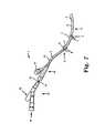
- FIG. 7schematically illustrates an embodiment of an anastomosis device of the present invention.
- FIG. 7shows an example of an anastomosis device of the present invention.
- Device 1includes distal end 8 , elongate catheter 2 , balloon 4 , and drainage aperture 6 .
- Two positionable tissue approximating structuresare illustrated as components of device 1 : proximal tissue approximating structure 5 , and distal tissue approximating structure 3 , each including a set of tines, 9 and 7 , respectively, that extend from and retract into the elongate catheter 2 .
- Device 1includes proximal end 15 that includes a port 17 that may connect to a lumen (not shown) such as an inflation lumen for balloon 4 or a drainage lumen from aperture 6 .
- Another port 19 , of an attachment 21can also be used with an inflation lumen or a drainage lumen.
- One or more wires 11 and 13connect to tissue approximating structures 5 , and 3 , e.g., as a positioning mechanism, for positioning tines 9 and 7 . Actuating mechanisms for each tissue approximating structure are described in detail below with reference to end portion 10 .
- end portion 10 of anastomosis device of the type described aboveis shown.
- end portion 10may be used in a different type of device to perform anastomosis or other surgical techniques which required external connection to internal tissues that require deployment of structures such as tines or tissue approximating structure, for example.
- End portion 10is generally located at the opposite end of the anastomosis device from the tip portion that is inserted inside the patient and is the portion of the device that will remain outside the patient.
- End portionincludes an actuation mechanism 12 that is used to manipulate the tissue approximation structures, see FIG.
- one actuation wire ( 11 and 13 in FIG. 7 ) or structureextends through a catheter body from each of the two sets of tissue approximating structures ( 7 and 9 in FIG. 7 ), for attachment to and/or communication with actuation mechanism 12 .
- Actuation mechanism 12generally includes a body 18 having a proximal end 14 and a distal end 16 .
- Distal end 16is attached to a shaft or other devices that extend from a catheter body, and proximal end 14 is the free or open end of body 18 .
- Body 18is a generally tubular body structure having walls 19 surrounding a central elongated opening 20 that is configured for activation and lockout, as described below.
- Body 18may further include at least one opening or window 21 that allows viewing into the central opening 20 , such as may be useful to determine the position of actuation wires or other components of the device.
- Actuation mechanism 12further includes an actuation insert 22 that is slideable within central opening 20 .
- Actuation insert 22includes a pair of trigger arms 24 that have a structure that is better shown in the exemplary embodiment of FIGS. 2-4 .
- trigger arms 24each include a flat end portion 26 extending from a curved portion 28 .
- Curved portions 28are preferably sized, shaped, and spaced relative to each other so that actuation insert 22 can slide relatively easily within central opening 20 of body 18 .
- Each of the curved portions 28further includes a snap tab 30 that has an elongated notch 32 on both of its sides (see FIG. 1 ) to allow for flexure of snap tab 30 .
- the walls 19 of body 18include two recessed areas 34 that are each sized and shaped correspondingly to accept a snap tab 30 when actuation insert 22 is inserted into opening 20 .
- actuation insert 22 of FIGS. 2-4is first assumed to be shown in the configuration in which the tissue approximating structures are in their undeployed or retracted positions within the attached catheter body. It is understood, however, that this configuration of actuation mechanism 12 is similar to the configuration of actuation mechanism 12 when both sets of tissue approximating structures are deployed or extended. Prior to deployment of the tissue approximating structures, snap tabs 30 are positioned within their respective recessed areas 34 to keep actuation insert 22 from moving or sliding along the length of body 18 .
- trigger arms 24are then again pressed or squeezed toward each other and actuation insert 22 is slid longitudinally back into body 18 until snap tabs 30 are again positioned within recessed areas 34 on the opposite sides of the device from which they were originally positioned.
- This movement of insert 22 back into body 18preferably moves an actuation wire until a second set of tissue approximating structures is deployed.
- Actuation insert 22may further include at least one directional arrow 50 to provide a visual reminder to the user of the direction that the insert 22 should be rotated for deployment or retraction of a particular set of tissue approximating structures.
- the opposite side of actuation insert 22may also include another arrow (not visible), which also is used to indicate the direction that the insert 22 should be rotated for a different set of tissue approximating structures.
- Arrow 50may optionally be color-coded or provided with another type of visual or tactile indicator of the position of a particular set of tissue approximating structures (e.g., to indicate which set of tissue approximating structures is in an active position).
- the color or other indicator on the arrowcan also be coordinated with a similarly colored band or other indicator that is at or near its respective tissue approximating structure, which may further be coordinated with a colored band or other indicator that can be visible through one of the windows 21 .
- the device 22may include a yellow arrow 50 , a yellow frame around one of the windows 21 , a yellow band at or near one of the sets of tissue approximating structures, and/or another yellow indicator inside the body 18 . In this way, the user can determine which set of tissue approximating structures will be activated by moving the actuation insert 22 , and can verify that the desired set of tissue approximating structures are deployed by a visual check of the yellow-framed window for a yellow indicator from inside the body 18 .
- Actuation mechanism 12preferably further includes a lockout device 40 that is shown in FIG. 1 as a relatively flat member that is pivotable about a pivot point 42 .
- Lockout device 40includes a flat portion 41 having an extending convenience tab 44 and a finger extension 46 .
- actuation insert 22When actuation insert 22 is in its inserted position within body 18 as is illustrated in FIG. 5 , lockout device 40 can be rotated about pivot point 42 until flat portion 41 is positioned between flat end portions 26 of trigger arms 24 . In this position, finger extension 46 will be inserted into an opening 48 of body 18 , which may be configured so that finger extension 46 will snap or otherwise positively engage within opening 48 to prevent lockout device 40 from unintentionally moving out of its position between trigger arms 24 .
- the lockout device 40may also be provided with a feature in place of or in addition to the finger extension 46 that can provide audible or tactile feedback to the user that the device 40 is in its lockout position. As is further shown in FIG. 1 , lockout device 40 cannot be rotated to be positioned between trigger arms 24 when insert 22 is in its intermediate position, but can only be used as a lockout device when insert 22 is in its locked position within opening 20 of the body. In this way, the tissue approximating structures are locked out from being either deployed or retracted when in either of these conditions. Further, convenience tab 44 is provided as a small extension from lockout device 40 that extends beyond the sides or ends of flat end portions 26 to allow the user to disengage lockout device 40 to pivot it around its pivot point 42 when it is desired to squeeze trigger arms 24 toward each other.
- actuation mechanism 12Although one embodiment of actuation mechanism 12 is described above, it is understood that many variations of the described and illustrated features are considered to be within the scope of the invention.
- flat end portions 26are preferably configured to provide an easy grip surface for the user's fingers; however, end portions 26 may be provided with a different size or shape that can more easily accommodate a tool, for example.
- lockout device 40may include a different configuration for finger extension 46 , or finger extension 46 may be eliminated from the device.
- snap tabs 30may be differently sized, shaped, or configured and/or only one of the trigger arms may include a snap tab 30 .
- FIG. 6illustrates another exemplary embodiment of an actuation mechanism 60 that employs a sequence of pulling, then twisting, then pushing of actuation wires to activate tissue approximation structures, such as for bladder and urethral tines.
- This deviceincludes advancement arms that “pull” an actuation wire to deploy one set of tissue approximating structures, such as bladder tines, then “push” an actuation wire to deploy another set of tissue approximating structures, such as urethral tines.
- a rotation of some portion of the actuation mechanismsshould desirably occur.
- the retraction of the tissue approximating structureswould then be achieved by performing the opposite actions (i.e, push vs. pull).
- the tissue approximating structuresare deployed or retracted in a predefined sequence (e.g., bladder tines then urethral tines) by a guiding arm 62 .
- the guiding arm 62engages a first advancement arm 64 and is pulled to advance one actuation wire 66 connected to a first set of tissue approximating structures (e.g., bladder tines).
- the guiding arm 62is then twisted and may disengage from the first advancement arm 64 , thereby leaving the first advancement arm 64 in a locked position.
- the guiding arm 62subsequently or simultaneously engages a second advancement arm 68 which unlocks it, and is then pushed to advance a second actuation wire 70 connected to a second set of tissue approximating structures (e.g., urethral tines).
- the second advancement arm 68may then be in a locked position.
- This predefined sequencecould instead be reversed to first push, then twist, then pull the guiding arm, or otherwise altered such that the second set of tissue approximating structures are deployed or retracted before the first set of tissue approximating structures.
- the various sequences of arm engagements and lockingmay vary in their order, and it is possible that only one of the advancement arms is lockable.
- This embodiment of the inventionmay also include a secondary lockout device or structure that provides a second manner of maintaining the advancement arms and actuation wires in their locked positions.
Landscapes
- Health & Medical Sciences (AREA)
- Life Sciences & Earth Sciences (AREA)
- Surgery (AREA)
- Heart & Thoracic Surgery (AREA)
- Engineering & Computer Science (AREA)
- Biomedical Technology (AREA)
- Nuclear Medicine, Radiotherapy & Molecular Imaging (AREA)
- Medical Informatics (AREA)
- Molecular Biology (AREA)
- Animal Behavior & Ethology (AREA)
- General Health & Medical Sciences (AREA)
- Public Health (AREA)
- Veterinary Medicine (AREA)
- Surgical Instruments (AREA)
Abstract
Description
Claims (13)
Priority Applications (1)
| Application Number | Priority Date | Filing Date | Title |
|---|---|---|---|
| US11/356,556US8636756B2 (en) | 2005-02-18 | 2006-02-17 | Anastomosis device and surgical tool actuation mechanism configurations |
Applications Claiming Priority (2)
| Application Number | Priority Date | Filing Date | Title |
|---|---|---|---|
| US65442305P | 2005-02-18 | 2005-02-18 | |
| US11/356,556US8636756B2 (en) | 2005-02-18 | 2006-02-17 | Anastomosis device and surgical tool actuation mechanism configurations |
Publications (2)
| Publication Number | Publication Date |
|---|---|
| US20060206122A1 US20060206122A1 (en) | 2006-09-14 |
| US8636756B2true US8636756B2 (en) | 2014-01-28 |
Family
ID=36972043
Family Applications (1)
| Application Number | Title | Priority Date | Filing Date |
|---|---|---|---|
| US11/356,556Active2031-02-25US8636756B2 (en) | 2005-02-18 | 2006-02-17 | Anastomosis device and surgical tool actuation mechanism configurations |
Country Status (1)
| Country | Link |
|---|---|
| US (1) | US8636756B2 (en) |
Families Citing this family (13)
| Publication number | Priority date | Publication date | Assignee | Title |
|---|---|---|---|---|
| US8636756B2 (en) | 2005-02-18 | 2014-01-28 | Ams Research Corporation | Anastomosis device and surgical tool actuation mechanism configurations |
| US7470275B2 (en)* | 2005-05-03 | 2008-12-30 | Ethicon Endo-Surgery, Inc. | Anastomotic ring applier device providing forward and retrograde visualization |
| US20070102170A1 (en)* | 2005-11-09 | 2007-05-10 | Waldack Larry E | Crimp Hub for Anastomosis Device |
| US8066725B2 (en)* | 2006-10-17 | 2011-11-29 | Ams Research Corporation | Anastomosis device having improved safety features |
| US8105318B2 (en)* | 2006-11-14 | 2012-01-31 | Ams Research Corporation | Introducer and valve cap for anastomosis device |
| US20080140098A1 (en)* | 2006-11-15 | 2008-06-12 | Monica Kumar | Anastomosis Balloon Configurations and device |
| US20080119729A1 (en)* | 2006-11-22 | 2008-05-22 | Copa Vincent G | Built-In Balloon Actuator for Urological Device |
| US20110118767A1 (en)* | 2008-07-30 | 2011-05-19 | Ams Research Corporation | Method and Apparatus for Determining Status of Approximation Structures on Anastomosis Device |
| US20110295287A1 (en)* | 2008-12-30 | 2011-12-01 | Ams Research Corporation | Actuation system for an anastomosis device |
| US8388349B2 (en)* | 2009-01-14 | 2013-03-05 | Ams Research Corporation | Anastomosis deployment force training tool |
| AU2011343593B2 (en) | 2010-12-16 | 2016-02-25 | Boston Scientific Scimed, Inc. | Micro-needle bladder balloon |
| US8747386B2 (en) | 2010-12-16 | 2014-06-10 | Ams Research Corporation | Anastomosis device and related methods |
| US11357955B2 (en) | 2011-09-01 | 2022-06-14 | Boston Scientific Scimed, Inc. | Devices, systems, and related methods for delivery of fluid to tissue |
Citations (69)
| Publication number | Priority date | Publication date | Assignee | Title |
|---|---|---|---|---|
| US4701162A (en) | 1985-09-24 | 1987-10-20 | The Kendall Company | Foley catheter assembly |
| US4705502A (en) | 1985-11-06 | 1987-11-10 | The Kendall Company | Suprapubic catheter with dual balloons |
| US4792330A (en) | 1987-07-13 | 1988-12-20 | Lazarus Medical Innovations, Inc. | Combination catheter and duct clamp apparatus and method |
| US4813934A (en) | 1987-08-07 | 1989-03-21 | Target Therapeutics | Valved catheter device and method |
| US4848367A (en) | 1987-02-11 | 1989-07-18 | Odis L. Avant | Method of effecting dorsal vein ligation |
| US4873977A (en) | 1987-02-11 | 1989-10-17 | Odis L. Avant | Stapling method and apparatus for vesicle-urethral re-anastomosis following retropubic prostatectomy and other tubular anastomosis |
| US4909785A (en) | 1986-03-25 | 1990-03-20 | American Medical Systems, Inc. | Method for valving body fluids |
| US4911164A (en) | 1988-04-26 | 1990-03-27 | Roth Robert A | Surgical tool and method of use |
| US4932956A (en) | 1988-05-10 | 1990-06-12 | American Medical Systems, Inc. | Prostate balloon dilator |
| US5047039A (en) | 1990-09-14 | 1991-09-10 | Odis Lynn Avant | Method and apparatus for effecting dorsal vein ligation and tubular anastomosis and laparoscopic prostatectomy |
| US5123908A (en) | 1989-01-26 | 1992-06-23 | Chen Fusen H | Anastomotic device |
| US5152772A (en) | 1991-07-10 | 1992-10-06 | Sewell Jr Frank | Sphincterotomy catheter and method |
| US5306226A (en) | 1989-02-09 | 1994-04-26 | Salama Fouad A | Urinary control with inflatable seal and method of using same |
| WO1996007447A1 (en) | 1994-09-02 | 1996-03-14 | Mauro Dimitri | Drainage catheter for urinary neo-bladders |
| US5540701A (en) | 1994-05-20 | 1996-07-30 | Hugh Sharkey | Passive fixation anastomosis method and device |
| US5545171A (en) | 1994-09-22 | 1996-08-13 | Vidamed, Inc. | Anastomosis catheter |
| US5643248A (en)* | 1995-02-07 | 1997-07-01 | Yoon; Inbae | Medical instrument with force limiting mechanism |
| US5653690A (en) | 1992-12-30 | 1997-08-05 | Medtronic, Inc. | Catheter having a balloon with retention enhancement |
| US5695504A (en) | 1995-02-24 | 1997-12-09 | Heartport, Inc. | Devices and methods for performing a vascular anastomosis |
| US5707380A (en) | 1996-07-23 | 1998-01-13 | United States Surgical Corporation | Anastomosis instrument and method |
| US5833698A (en) | 1996-07-23 | 1998-11-10 | United States Surgical Corporation | Anastomosis instrument and method |
| WO1999016359A1 (en) | 1997-09-26 | 1999-04-08 | Cryolife, Inc. | Sutureless anastomotic technique using a bioadhesive and device therefor |
| WO1999021490A1 (en) | 1997-06-28 | 1999-05-06 | Transvascular, Inc. | Transluminal methods and apparatus for closing, forming attachments to, and/or forming anastomotic junctions in, luminal anatomical structures |
| WO1999021491A1 (en) | 1997-10-24 | 1999-05-06 | Suyker Wilhelmus Jospeh Leonar | Mechanical anastomosis system for hollow structures |
| US5931842A (en) | 1996-11-07 | 1999-08-03 | Vascular Science Inc. | Methods and apparatus for handling tubing used in medical procedures |
| US5964791A (en) | 1995-05-18 | 1999-10-12 | Prostalund Operations Ab | Apparatus for heat treatment of tissue |
| WO1999058081A2 (en) | 1998-05-11 | 1999-11-18 | Hovland Claire T | Devices and methods for treating e.g. urinary stress incontinence |
| US6024748A (en) | 1996-07-23 | 2000-02-15 | United States Surgical Corporation | Singleshot anastomosis instrument with detachable loading unit and method |
| US6119045A (en) | 1995-05-12 | 2000-09-12 | Prostalund Operations Ab | Device for maintaining a passage for urine through the prostate |
| WO2000078226A1 (en)* | 1999-06-18 | 2000-12-28 | Radi Medical Systems Ab | A tool, a sealing device, a system and a method for closing a wound |
| US6193734B1 (en) | 1998-01-23 | 2001-02-27 | Heartport, Inc. | System for performing vascular anastomoses |
| US6238368B1 (en) | 1994-07-13 | 2001-05-29 | Marian Devonec | Therapeutic device for the selective cytoreduction treatment of an obstruction |
| US6254570B1 (en) | 1997-04-07 | 2001-07-03 | Vance Products, Inc. | Back-up retention member drainage catheter |
| US6299598B1 (en) | 1997-02-04 | 2001-10-09 | Cook Urological, Incorporated | Drainage catheter |
| US20010049492A1 (en) | 1999-09-20 | 2001-12-06 | Frazier Andrew G.C. | Anastomosis catheter |
| US20020002363A1 (en) | 2000-04-27 | 2002-01-03 | Ryuichi Urakawa | Catheter and medical tube |
| US6391039B1 (en) | 1996-07-23 | 2002-05-21 | United States Surgical Corporation | Anastomosis instrument and method |
| US20020087176A1 (en) | 2000-10-10 | 2002-07-04 | Greenhalgh E. Skott | Anastomosis device |
| US6416545B1 (en) | 1996-04-09 | 2002-07-09 | Endocare, Inc. | Urological stent therapy system and method |
| US6440146B2 (en) | 1996-07-23 | 2002-08-27 | United States Surgical Corporation | Anastomosis instrument and method |
| US6447533B1 (en) | 1998-05-26 | 2002-09-10 | Scimed Life Systems, Inc. | Implantable tissue fastener and system for treating gastroesophageal reflux disease |
| US6461367B1 (en) | 1999-07-16 | 2002-10-08 | Loma Linda University Medical Center | Method and device for urethral-vesicle anastomosis |
| US6494908B1 (en) | 1999-12-22 | 2002-12-17 | Ethicon, Inc. | Removable stent for body lumens |
| US6520974B2 (en) | 1997-06-30 | 2003-02-18 | Eva Corporation | Surgical fastener |
| US6530932B1 (en) | 2000-08-30 | 2003-03-11 | Ethicon Endo-Surgery, Inc. | Anastomosis device having improved tissue presentation |
| US20030069629A1 (en) | 2001-06-01 | 2003-04-10 | Jadhav Balkrishna S. | Bioresorbable medical devices |
| US6562024B2 (en) | 1997-08-14 | 2003-05-13 | Scimed Life Systems, Inc. | Drainage catheter delivery system |
| US6599311B1 (en) | 1998-06-05 | 2003-07-29 | Broncus Technologies, Inc. | Method and assembly for lung volume reduction |
| US6602243B2 (en) | 2000-12-15 | 2003-08-05 | Alsius Corporation | Foley catheter having redundant temperature sensors and method |
| US20030208183A1 (en) | 2000-08-07 | 2003-11-06 | Whalen Mark J. | Endourethral device & method |
| US20030229364A1 (en) | 2002-06-11 | 2003-12-11 | Michael Seiba | Device for anastomosis in a radical retropubic prostatectomy |
| WO2004000138A1 (en) | 2002-06-19 | 2003-12-31 | Tyco Healthcare Group Lp | Method and apparatus for anastomosis |
| WO2004000136A2 (en) | 2002-06-20 | 2003-12-31 | Tyco Healthcare Group, Lp | Method and apparatus for anastomosis including an anchoring sleeve |
| WO2004000137A2 (en) | 2002-06-19 | 2003-12-31 | Tyco Healthcare Group Lp | Method and apparatus for radical prostatectomy anastomosis |
| WO2004000135A2 (en) | 2002-06-20 | 2003-12-31 | Tyco Healthcare Group, Lp | Method and apparatus for anastomosis including an anchoring sleeve |
| US6695832B2 (en) | 2000-06-01 | 2004-02-24 | Twincath, Llc | Multilumen catheter and methods for making the catheter |
| US6719749B1 (en) | 2000-06-01 | 2004-04-13 | Medical Components, Inc. | Multilumen catheter assembly and methods for making and inserting the same |
| US6719709B2 (en) | 2000-08-31 | 2004-04-13 | Abbeymoor Medical, Inc. | Diagnostic urethral assembly and method |
| WO2004034913A1 (en) | 2002-10-16 | 2004-04-29 | Civco Medical Instruments Inc. | Suturing system and method |
| US20040087995A1 (en) | 2002-08-22 | 2004-05-06 | Copa Vincent G. | Anastomosis device and related methods |
| US6740098B2 (en) | 1998-05-11 | 2004-05-25 | Surgical Connections, Inc. | Surgical stabilizer devices and methods |
| US6746456B2 (en) | 2001-09-28 | 2004-06-08 | Ethicon, Inc. | Needle array suturing/sewing anastomosis device and method for anastomosis |
| US20050070938A1 (en) | 2002-08-22 | 2005-03-31 | Copa Vincent G. | Anastomosis device and related methods |
| US20050131431A1 (en) | 2002-08-22 | 2005-06-16 | Copa Vincent G. | Anastomosis device and related methods |
| US20050288764A1 (en) | 2004-06-28 | 2005-12-29 | Xtent, Inc. | Devices and methods for controlling expandable prosthesis during develoyment |
| US20060200178A1 (en) | 2005-02-18 | 2006-09-07 | Hamel Kory P | Anastomosis device catheter and sheath constructions |
| US20060206122A1 (en) | 2005-02-18 | 2006-09-14 | Copa Vincent G | Anastomosis device and surgical tool actuation mechanism configurations |
| US20060264985A1 (en) | 2005-05-20 | 2006-11-23 | Copa Vincent G | Anastomosis device approximating structure configurations |
| US20060276811A1 (en) | 2005-05-20 | 2006-12-07 | Copa Vincent G | Anastomosis device configurations and methods |
- 2006
- 2006-02-17USUS11/356,556patent/US8636756B2/enactiveActive
Patent Citations (83)
| Publication number | Priority date | Publication date | Assignee | Title |
|---|---|---|---|---|
| US4701162A (en) | 1985-09-24 | 1987-10-20 | The Kendall Company | Foley catheter assembly |
| US4705502A (en) | 1985-11-06 | 1987-11-10 | The Kendall Company | Suprapubic catheter with dual balloons |
| US4909785A (en) | 1986-03-25 | 1990-03-20 | American Medical Systems, Inc. | Method for valving body fluids |
| US4848367A (en) | 1987-02-11 | 1989-07-18 | Odis L. Avant | Method of effecting dorsal vein ligation |
| US4873977A (en) | 1987-02-11 | 1989-10-17 | Odis L. Avant | Stapling method and apparatus for vesicle-urethral re-anastomosis following retropubic prostatectomy and other tubular anastomosis |
| US4792330A (en) | 1987-07-13 | 1988-12-20 | Lazarus Medical Innovations, Inc. | Combination catheter and duct clamp apparatus and method |
| US4813934B1 (en) | 1987-08-07 | 1992-05-12 | Target Therapeutics Inc | |
| US4813934A (en) | 1987-08-07 | 1989-03-21 | Target Therapeutics | Valved catheter device and method |
| US4911164A (en) | 1988-04-26 | 1990-03-27 | Roth Robert A | Surgical tool and method of use |
| US4932956A (en) | 1988-05-10 | 1990-06-12 | American Medical Systems, Inc. | Prostate balloon dilator |
| US5123908A (en) | 1989-01-26 | 1992-06-23 | Chen Fusen H | Anastomotic device |
| US5306226A (en) | 1989-02-09 | 1994-04-26 | Salama Fouad A | Urinary control with inflatable seal and method of using same |
| WO1992004869A1 (en) | 1990-09-14 | 1992-04-02 | Avant Odis L | A method and apparatus for effecting dorsal vein ligation |
| US5047039A (en) | 1990-09-14 | 1991-09-10 | Odis Lynn Avant | Method and apparatus for effecting dorsal vein ligation and tubular anastomosis and laparoscopic prostatectomy |
| US5152772A (en) | 1991-07-10 | 1992-10-06 | Sewell Jr Frank | Sphincterotomy catheter and method |
| US5653690A (en) | 1992-12-30 | 1997-08-05 | Medtronic, Inc. | Catheter having a balloon with retention enhancement |
| US5540701A (en) | 1994-05-20 | 1996-07-30 | Hugh Sharkey | Passive fixation anastomosis method and device |
| US6238368B1 (en) | 1994-07-13 | 2001-05-29 | Marian Devonec | Therapeutic device for the selective cytoreduction treatment of an obstruction |
| WO1996007447A1 (en) | 1994-09-02 | 1996-03-14 | Mauro Dimitri | Drainage catheter for urinary neo-bladders |
| US5545171A (en) | 1994-09-22 | 1996-08-13 | Vidamed, Inc. | Anastomosis catheter |
| US5643248A (en)* | 1995-02-07 | 1997-07-01 | Yoon; Inbae | Medical instrument with force limiting mechanism |
| US5695504A (en) | 1995-02-24 | 1997-12-09 | Heartport, Inc. | Devices and methods for performing a vascular anastomosis |
| US6119045A (en) | 1995-05-12 | 2000-09-12 | Prostalund Operations Ab | Device for maintaining a passage for urine through the prostate |
| US5964791A (en) | 1995-05-18 | 1999-10-12 | Prostalund Operations Ab | Apparatus for heat treatment of tissue |
| US6416545B1 (en) | 1996-04-09 | 2002-07-09 | Endocare, Inc. | Urological stent therapy system and method |
| US6391039B1 (en) | 1996-07-23 | 2002-05-21 | United States Surgical Corporation | Anastomosis instrument and method |
| US5707380A (en) | 1996-07-23 | 1998-01-13 | United States Surgical Corporation | Anastomosis instrument and method |
| US6024748A (en) | 1996-07-23 | 2000-02-15 | United States Surgical Corporation | Singleshot anastomosis instrument with detachable loading unit and method |
| US6440146B2 (en) | 1996-07-23 | 2002-08-27 | United States Surgical Corporation | Anastomosis instrument and method |
| US5833698A (en) | 1996-07-23 | 1998-11-10 | United States Surgical Corporation | Anastomosis instrument and method |
| US6726697B2 (en) | 1996-07-23 | 2004-04-27 | United States Surgical Corporation | Anastomosis instrument and method |
| US20040078047A1 (en) | 1996-07-23 | 2004-04-22 | Nicholas David A. | Anastomosis instrument and method |
| US5931842A (en) | 1996-11-07 | 1999-08-03 | Vascular Science Inc. | Methods and apparatus for handling tubing used in medical procedures |
| US6302905B1 (en) | 1996-11-07 | 2001-10-16 | St. Jude Medical Cardiovascular Group Inc. | Medical grafting methods and apparatus |
| US6299598B1 (en) | 1997-02-04 | 2001-10-09 | Cook Urological, Incorporated | Drainage catheter |
| US6254570B1 (en) | 1997-04-07 | 2001-07-03 | Vance Products, Inc. | Back-up retention member drainage catheter |
| WO1999021490A1 (en) | 1997-06-28 | 1999-05-06 | Transvascular, Inc. | Transluminal methods and apparatus for closing, forming attachments to, and/or forming anastomotic junctions in, luminal anatomical structures |
| US6520974B2 (en) | 1997-06-30 | 2003-02-18 | Eva Corporation | Surgical fastener |
| US6562024B2 (en) | 1997-08-14 | 2003-05-13 | Scimed Life Systems, Inc. | Drainage catheter delivery system |
| WO1999016359A1 (en) | 1997-09-26 | 1999-04-08 | Cryolife, Inc. | Sutureless anastomotic technique using a bioadhesive and device therefor |
| US6485496B1 (en) | 1997-10-24 | 2002-11-26 | Wilhelmus Joseph Leonardus Suyker | Mechanical anastomosis system for hollow structures |
| WO1999021491A1 (en) | 1997-10-24 | 1999-05-06 | Suyker Wilhelmus Jospeh Leonar | Mechanical anastomosis system for hollow structures |
| US6193734B1 (en) | 1998-01-23 | 2001-02-27 | Heartport, Inc. | System for performing vascular anastomoses |
| US6149667A (en) | 1998-05-11 | 2000-11-21 | Surgical Connections, Inc. | Devices and methods for treating E.G. urinary stress incontinence |
| US6740098B2 (en) | 1998-05-11 | 2004-05-25 | Surgical Connections, Inc. | Surgical stabilizer devices and methods |
| WO1999058081A2 (en) | 1998-05-11 | 1999-11-18 | Hovland Claire T | Devices and methods for treating e.g. urinary stress incontinence |
| US6447533B1 (en) | 1998-05-26 | 2002-09-10 | Scimed Life Systems, Inc. | Implantable tissue fastener and system for treating gastroesophageal reflux disease |
| US6599311B1 (en) | 1998-06-05 | 2003-07-29 | Broncus Technologies, Inc. | Method and assembly for lung volume reduction |
| WO2000078226A1 (en)* | 1999-06-18 | 2000-12-28 | Radi Medical Systems Ab | A tool, a sealing device, a system and a method for closing a wound |
| US6565579B2 (en) | 1999-07-16 | 2003-05-20 | Loma Linda University Medical Center | Method and device for urethral-vesicle anastomosis |
| US6461367B1 (en) | 1999-07-16 | 2002-10-08 | Loma Linda University Medical Center | Method and device for urethral-vesicle anastomosis |
| US6702825B2 (en) | 1999-09-20 | 2004-03-09 | Ev3 Sunnyvale, Inc. | Anastomosis catheter |
| US6746472B2 (en) | 1999-09-20 | 2004-06-08 | Ev3 Sunnyvale, Inc. | Endoluminal anchor |
| US20010049492A1 (en) | 1999-09-20 | 2001-12-06 | Frazier Andrew G.C. | Anastomosis catheter |
| US6494908B1 (en) | 1999-12-22 | 2002-12-17 | Ethicon, Inc. | Removable stent for body lumens |
| US20020002363A1 (en) | 2000-04-27 | 2002-01-03 | Ryuichi Urakawa | Catheter and medical tube |
| US6695832B2 (en) | 2000-06-01 | 2004-02-24 | Twincath, Llc | Multilumen catheter and methods for making the catheter |
| US6719749B1 (en) | 2000-06-01 | 2004-04-13 | Medical Components, Inc. | Multilumen catheter assembly and methods for making and inserting the same |
| US20030208183A1 (en) | 2000-08-07 | 2003-11-06 | Whalen Mark J. | Endourethral device & method |
| US6530932B1 (en) | 2000-08-30 | 2003-03-11 | Ethicon Endo-Surgery, Inc. | Anastomosis device having improved tissue presentation |
| US6719709B2 (en) | 2000-08-31 | 2004-04-13 | Abbeymoor Medical, Inc. | Diagnostic urethral assembly and method |
| US20020087176A1 (en) | 2000-10-10 | 2002-07-04 | Greenhalgh E. Skott | Anastomosis device |
| US6602243B2 (en) | 2000-12-15 | 2003-08-05 | Alsius Corporation | Foley catheter having redundant temperature sensors and method |
| US20030069629A1 (en) | 2001-06-01 | 2003-04-10 | Jadhav Balkrishna S. | Bioresorbable medical devices |
| US6746456B2 (en) | 2001-09-28 | 2004-06-08 | Ethicon, Inc. | Needle array suturing/sewing anastomosis device and method for anastomosis |
| US20030229364A1 (en) | 2002-06-11 | 2003-12-11 | Michael Seiba | Device for anastomosis in a radical retropubic prostatectomy |
| US20050251155A1 (en) | 2002-06-19 | 2005-11-10 | Orban Joseph P Iii | Method and apparatus for anastomosis |
| WO2004000137A2 (en) | 2002-06-19 | 2003-12-31 | Tyco Healthcare Group Lp | Method and apparatus for radical prostatectomy anastomosis |
| WO2004000138A1 (en) | 2002-06-19 | 2003-12-31 | Tyco Healthcare Group Lp | Method and apparatus for anastomosis |
| WO2004000135A2 (en) | 2002-06-20 | 2003-12-31 | Tyco Healthcare Group, Lp | Method and apparatus for anastomosis including an anchoring sleeve |
| US20050192602A1 (en) | 2002-06-20 | 2005-09-01 | Scott Manzo | Method and apparatus for anastomosis including an anchoring sleeve |
| WO2004000136A2 (en) | 2002-06-20 | 2003-12-31 | Tyco Healthcare Group, Lp | Method and apparatus for anastomosis including an anchoring sleeve |
| US20040087995A1 (en) | 2002-08-22 | 2004-05-06 | Copa Vincent G. | Anastomosis device and related methods |
| US20050070938A1 (en) | 2002-08-22 | 2005-03-31 | Copa Vincent G. | Anastomosis device and related methods |
| US20050131431A1 (en) | 2002-08-22 | 2005-06-16 | Copa Vincent G. | Anastomosis device and related methods |
| US20070219584A1 (en) | 2002-08-22 | 2007-09-20 | Copa Vincent G | Anastomosis device and related methods |
| US6821283B2 (en) | 2002-10-16 | 2004-11-23 | Civco Medical Instruments, Inc. | Suturing system and method |
| WO2004034913A1 (en) | 2002-10-16 | 2004-04-29 | Civco Medical Instruments Inc. | Suturing system and method |
| US20050288764A1 (en) | 2004-06-28 | 2005-12-29 | Xtent, Inc. | Devices and methods for controlling expandable prosthesis during develoyment |
| US20060200178A1 (en) | 2005-02-18 | 2006-09-07 | Hamel Kory P | Anastomosis device catheter and sheath constructions |
| US20060206122A1 (en) | 2005-02-18 | 2006-09-14 | Copa Vincent G | Anastomosis device and surgical tool actuation mechanism configurations |
| US20060264985A1 (en) | 2005-05-20 | 2006-11-23 | Copa Vincent G | Anastomosis device approximating structure configurations |
| US20060276811A1 (en) | 2005-05-20 | 2006-12-07 | Copa Vincent G | Anastomosis device configurations and methods |
Non-Patent Citations (2)
| Title |
|---|
| Acconcia et al., "Sutureless" Vesicourethral Anastomosis in Radical Retropubic Prostatectomy, The American Journal of Urology Review, vol. 1, No. 2, pp. 93-96 (Mar./Apr. 2003). |
| Igel et al., "Comparison of Techniques for Vesicourethral Anastomosis: Simple Direct Versus Modified Vest Traction Sutures," Urology, vol. XXXI, No. 6, pp. 474-477 (Jun. 1988). |
Also Published As
| Publication number | Publication date |
|---|---|
| US20060206122A1 (en) | 2006-09-14 |
Similar Documents
| Publication | Publication Date | Title |
|---|---|---|
| US8636756B2 (en) | Anastomosis device and surgical tool actuation mechanism configurations | |
| US11779326B2 (en) | Stitching device with long needle | |
| US11311297B2 (en) | Devices for approximating tissue and related methods of use | |
| US10595856B2 (en) | Stitching device with long needle delivery | |
| EP2934347B1 (en) | Applicators for modular magnetic anastomosis device | |
| EP3437571B1 (en) | Medical devices with detachable pivotable jaws | |
| US9044239B2 (en) | Multiple clip deployment magazine | |
| EP2627264B1 (en) | Medical devices with detachable pivotable jaws | |
| US8277467B2 (en) | Anastomosis device configurations and methods | |
| US11129623B2 (en) | Dual support jaw design | |
| US20190142405A1 (en) | Triple pronged clip | |
| EP4243707B1 (en) | Repositional clip with extension | |
| US20230134917A1 (en) | System, apparatus, and method for suturing | |
| US20030014065A1 (en) | Endoscopic instrument | |
| JP2023539519A (en) | Clamping system and method for luminal attachment crimp or wound defect | |
| US20230181196A1 (en) | Repositionable over the scope clip |
Legal Events
| Date | Code | Title | Description |
|---|---|---|---|
| AS | Assignment | Owner name:AMS RESEARCH CORPORATION, MINNESOTA Free format text:ASSIGNMENT OF ASSIGNORS INTEREST;ASSIGNORS:COPA, VINCENT G.;HAUSCHILD, SIDNEY F.;HAMEL, KORY P.;SIGNING DATES FROM 20060515 TO 20060516;REEL/FRAME:017650/0442 Owner name:AMS RESEARCH CORPORATION, MINNESOTA Free format text:ASSIGNMENT OF ASSIGNORS INTEREST;ASSIGNORS:COPA, VINCENT G.;HAUSCHILD, SIDNEY F.;HAMEL, KORY P.;REEL/FRAME:017650/0442;SIGNING DATES FROM 20060515 TO 20060516 | |
| AS | Assignment | Owner name:MORGAN STANLEY SENIOR FUNDING, INC., AS ADMINISTRA Free format text:SECURITY AGREEMENT;ASSIGNOR:AMS RESEARCH CORPORATION;REEL/FRAME:026632/0535 Effective date:20110617 | |
| STCF | Information on status: patent grant | Free format text:PATENTED CASE | |
| AS | Assignment | Owner name:AMS RESEARCH CORPORATION, MINNESOTA Free format text:RELEASE OF PATENT SECURITY INTEREST;ASSIGNOR:MORGAN STANLEY SENIOR FUNDING, INC., AS ADMINISTRATIVE AGENT;REEL/FRAME:032380/0053 Effective date:20140228 | |
| AS | Assignment | Owner name:DEUTSCHE BANK AG NEW YORK BRANCH, AS COLLATERAL AGENT, NEW YORK Free format text:GRANT OF SECURITY INTEREST IN PATENTS;ASSIGNORS:ENDO PHARMACEUTICALS SOLUTIONS, INC.;ENDO PHARMACEUTICALS, INC.;AMS RESEARCH CORPORATION;AND OTHERS;REEL/FRAME:032491/0440 Effective date:20140228 Owner name:DEUTSCHE BANK AG NEW YORK BRANCH, AS COLLATERAL AG Free format text:GRANT OF SECURITY INTEREST IN PATENTS;ASSIGNORS:ENDO PHARMACEUTICALS SOLUTIONS, INC.;ENDO PHARMACEUTICALS, INC.;AMS RESEARCH CORPORATION;AND OTHERS;REEL/FRAME:032491/0440 Effective date:20140228 | |
| AS | Assignment | Owner name:LASERSCOPE, CALIFORNIA Free format text:RELEASE BY SECURED PARTY;ASSIGNOR:DEUTSCHE BANK AG NEW YORK BRANCH;REEL/FRAME:036285/0146 Effective date:20150803 Owner name:AMS RESEARCH, LLC, MINNESOTA Free format text:RELEASE BY SECURED PARTY;ASSIGNOR:DEUTSCHE BANK AG NEW YORK BRANCH;REEL/FRAME:036285/0146 Effective date:20150803 Owner name:AMERICAN MEDICAL SYSTEMS, LLC, MINNESOTA Free format text:RELEASE BY SECURED PARTY;ASSIGNOR:DEUTSCHE BANK AG NEW YORK BRANCH;REEL/FRAME:036285/0146 Effective date:20150803 | |
| AS | Assignment | Owner name:BOSTON SCIENTIFIC SCIMED, INC., MINNESOTA Free format text:ASSIGNMENT OF ASSIGNORS INTEREST;ASSIGNOR:AMERICAN MEDICAL SYSTEMS, LLC;REEL/FRAME:037902/0200 Effective date:20151210 Owner name:BOSTON SCIENTIFIC SCIMED, INC., MINNESOTA Free format text:ASSIGNMENT OF ASSIGNORS INTEREST;ASSIGNOR:AMS RESEARCH, LLC;REEL/FRAME:037902/0162 Effective date:20151210 | |
| FPAY | Fee payment | Year of fee payment:4 | |
| MAFP | Maintenance fee payment | Free format text:PAYMENT OF MAINTENANCE FEE, 8TH YEAR, LARGE ENTITY (ORIGINAL EVENT CODE: M1552); ENTITY STATUS OF PATENT OWNER: LARGE ENTITY Year of fee payment:8 | |
| MAFP | Maintenance fee payment | Free format text:PAYMENT OF MAINTENANCE FEE, 12TH YEAR, LARGE ENTITY (ORIGINAL EVENT CODE: M1553); ENTITY STATUS OF PATENT OWNER: LARGE ENTITY Year of fee payment:12 |