US8636714B2 - Microcatheter with sleeved guidewire port - Google Patents
Microcatheter with sleeved guidewire portDownload PDFInfo
- Publication number
- US8636714B2 US8636714B2US10/667,056US66705603AUS8636714B2US 8636714 B2US8636714 B2US 8636714B2US 66705603 AUS66705603 AUS 66705603AUS 8636714 B2US8636714 B2US 8636714B2
- Authority
- US
- United States
- Prior art keywords
- guidewire
- polymer sheath
- elongate shaft
- guidewire port
- sheath
- Prior art date
- Legal status (The legal status is an assumption and is not a legal conclusion. Google has not performed a legal analysis and makes no representation as to the accuracy of the status listed.)
- Active, expires
Links
Images


Classifications
- A—HUMAN NECESSITIES
- A61—MEDICAL OR VETERINARY SCIENCE; HYGIENE
- A61M—DEVICES FOR INTRODUCING MEDIA INTO, OR ONTO, THE BODY; DEVICES FOR TRANSDUCING BODY MEDIA OR FOR TAKING MEDIA FROM THE BODY; DEVICES FOR PRODUCING OR ENDING SLEEP OR STUPOR
- A61M25/00—Catheters; Hollow probes
- A61M25/0067—Catheters; Hollow probes characterised by the distal end, e.g. tips
- A61M25/0074—Dynamic characteristics of the catheter tip, e.g. openable, closable, expandable or deformable
- A61M25/0075—Valve means
- A—HUMAN NECESSITIES
- A61—MEDICAL OR VETERINARY SCIENCE; HYGIENE
- A61M—DEVICES FOR INTRODUCING MEDIA INTO, OR ONTO, THE BODY; DEVICES FOR TRANSDUCING BODY MEDIA OR FOR TAKING MEDIA FROM THE BODY; DEVICES FOR PRODUCING OR ENDING SLEEP OR STUPOR
- A61M25/00—Catheters; Hollow probes
- A61M25/0067—Catheters; Hollow probes characterised by the distal end, e.g. tips
- A61M25/0068—Static characteristics of the catheter tip, e.g. shape, atraumatic tip, curved tip or tip structure
- A61M25/007—Side holes, e.g. their profiles or arrangements; Provisions to keep side holes unblocked
- A—HUMAN NECESSITIES
- A61—MEDICAL OR VETERINARY SCIENCE; HYGIENE
- A61M—DEVICES FOR INTRODUCING MEDIA INTO, OR ONTO, THE BODY; DEVICES FOR TRANSDUCING BODY MEDIA OR FOR TAKING MEDIA FROM THE BODY; DEVICES FOR PRODUCING OR ENDING SLEEP OR STUPOR
- A61M25/00—Catheters; Hollow probes
- A61M25/0021—Catheters; Hollow probes characterised by the form of the tubing
- A61M2025/0042—Microcatheters, cannula or the like having outside diameters around 1 mm or less
- A—HUMAN NECESSITIES
- A61—MEDICAL OR VETERINARY SCIENCE; HYGIENE
- A61M—DEVICES FOR INTRODUCING MEDIA INTO, OR ONTO, THE BODY; DEVICES FOR TRANSDUCING BODY MEDIA OR FOR TAKING MEDIA FROM THE BODY; DEVICES FOR PRODUCING OR ENDING SLEEP OR STUPOR
- A61M25/00—Catheters; Hollow probes
- A61M25/01—Introducing, guiding, advancing, emplacing or holding catheters
- A61M25/06—Body-piercing guide needles or the like
- A61M25/0662—Guide tubes
- A61M2025/0681—Systems with catheter and outer tubing, e.g. sheath, sleeve or guide tube
Definitions
- the present inventionrelates generally to catheters for delivery of therapeutic agents or devices to a site within a body lumen. More particularly, the present invention is directed to microcatheters used to navigate the neurovascular system.
- a variety of intravascular cathetersare known, including small diameter catheters that are configured for use in smaller vasculature such as the neurovasculature. Such catheters are known as microcatheters. Many microcatheters have a single lumen designed to accommodate a guidewire, treatment device or fluid that may be deployed through the single microcatheter lumen.
- the inventionis directed to microcatheters that have a proximal guidewire port and a distal guidewire port.
- the proximal guidewire portcan be positioned proximal of the distal end of the microcatheter, while the distal guidewire port can be positioned proximate the distal end of the microcatheter.
- the proximal guidewire portis located distal of the proximal end of the shaft to provide rapid exchange capability.
- the guidewire portcan include a valve member that permits guidewire access through the catheter wall to a lumen of the microcatheter while providing a substantially fluid tight seal at least when the guidewire is not present in the guidewire port.
- the valve membercan function to cover the port such that coils or other treatment means, such as a stent, do not catch on the port when advanced through the lumen.
- an example embodiment of the inventioncan be found in a microcatheter that includes an elongate shaft that has a distal end, a proximal end and a lumen extending therebetween.
- the catheterincludes a single lumen.
- a guidewire portcan be positioned proximal of the distal end of the elongate shaft, and a control valve can be positioned exterior to the shaft lumen and overlying the guidewire port.
- the control valvecan be configured to be moveable between a closed position and an open position with penetration of the control valve.
- a single lumen microcatheterhaving an elongate shaft that has a distal end and a proximal end.
- the elongate shaftcan have an inner surface and an outer surface, and the inner surface can define a lumen that extends through the elongate shaft.
- a guidewire portcan be positioned proximal of the distal end of the elongate shaft and can extend from the inner surface of the elongate shaft to the outer surface of the elongate shaft.
- a polymer sheath having an inner surface and an outer surfacecan be disposed over the guidewire port.
- the polymer sheathcan include an angled slit that is in communication with the guidewire port. The angled slit can be configured to permit guidewire access through the guidewire port while remaining fluid tight when no guidewire is provided through the angled slit.
- the microcathetercan include an elongate shaft, a guidewire port and a control valve disposed to overlay the guidewire port.
- a guidewire sheathcan be advanced through the control valve and through the guidewire port.
- a guidewirecan be advanced through the guidewire sheath, and the microcatheter can be advanced over the guidewire to a treatment site.
- the guidewire sheathmay not be utilized, but instead, the guidewire is passed directly through the control valve.
- the guidewire and the guidewire sheathcan be removed, thereby closing the guidewire port.
- the therapeutic elementcan be advanced or a therapeutic substance delivered through the elongate shaft, past the closed guidewire port, to the treatment site.
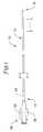
- FIG. 1is a plan view of a microcatheter in accordance with an embodiment of the invention
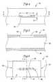
- FIG. 2is a cross-sectional view of the microcatheter of FIG. 1 , taken along line 2 - 2 ;
- FIG. 3is a partial longitudinal section view of a portion of a microcatheter, in accordance with an embodiment of the invention.
- FIG. 4is a plan view of the 4 - 4 portion of FIG. 1 ;
- FIG. 5is a cross-sectional view of the microcatheter portion of FIG. 4 , taken along line 5 - 5 ;
- FIG. 6shows FIG. 4 , with the addition of a polymer sheath including a control valve
- FIG. 7is a cross-sectional view of the microcatheter portion of FIG. 6 , taken along line 7 - 7 ;
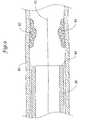
- FIG. 8is a partially sectioned view of the microcatheter portion of FIG. 5 , showing a guidewire sheath and a guidewire disposed therein;
- FIG. 9is a partially sectioned view showing the distal portion of the microcatheter of FIG. 8 deployed within a patient's vasculature.
- FIG. 1is a plan view of a catheter 10 in accordance with an embodiment of the present invention.
- the catheter 10can be one of a variety of different catheters, but is preferably an intravascular catheter. Examples of some intravascular catheters include microcatheters, drug delivery catheters, diagnostic catheters and guide catheters. As illustrated, FIG. 1 portrays a microcatheter, but the invention is not limited to such. Except as described herein, the intravascular catheter 10 can be manufactured using conventional techniques.
- the intravascular catheter 10can be sized in accordance with its intended use.
- the catheter 10can have a length that is in the range of about 50 to 200 centimeters and can have a diameter that is in the range of about 1.7 F (French), but can be as large as about 12 F for certain applications.
- French1.7 F
- the intravascular catheter 10includes an elongate shaft 12 that has a proximal end 14 and a distal end 16 .
- a hub and strain relief assembly 18can be connected to or disposed about the proximal end 14 of the elongate shaft 12 .
- the hub and strain relief assembly 18includes a main body portion 20 , a pair of flanges 22 designed to improve gripping, and a strain relief 24 that is intended to reduce kinking.
- the hub and strain relief assembly 18can be of conventional design and can be attached using conventional techniques.
- FIG. 2is a cross-sectional view of the elongate shaft 12 , taken along line 2 - 2 of FIG. 1 .
- a lumen 30extends through the elongate shaft 12 .
- the elongate shaft 12is formed of a single polymer layer 28 , which can be any suitable polymeric material such as a thermoplastic polymer material.
- the single polymer layer 28can be extruded or otherwise formed from a single polymer or from a blend of polymers.
- the elongate shaft 12can also include additional polymer layers.
- FIG. 3illustrates a portion of another exemplary elongate shaft 32 that includes an outer polymer layer 34 , an inner polymer layer 36 , and an intermediate reinforcing layer 38 .
- the inner polymer layer 36can be formed of or include a coating of a material having a suitably low coefficient of friction. Examples of suitable materials include polytetrafluoroethylene (PTFE), better known as TEFLON®.
- PTFEpolytetrafluoroethylene
- the inner layer 36can be dimensioned to define a lumen 30 having an appropriate inner diameter to accommodate its intended use.
- the inner layer 36can define a lumen 30 having a diameter of about 0.0165 inches and can have a wall thickness of about 0.001 inches.
- the outer polymer layer 34can be formed from any suitable polymer that will provide the desired strength, flexibility or other desired characteristics. Polymers with low durometer or hardness can provide increased flexibility, while polymers with high durometer or hardness can provide increased stiffness.
- the polymer material usedis a thermoplastic polymer material. Some examples of some suitable materials include polyurethane, elastomeric polyamides, block polyamide/ethers (such as PEBAX), silicones, and co-polymers.
- the outer layer 34can be a single polymer, multiple longitudinal sections or layers, or a blend of polymers. By employing careful selection of materials and processing techniques, thermoplastic, solvent soluble, and thermosetting variants of these materials can be employed to achieve the desired results.
- thermoplastic polymersuch as a co-polyester thermoplastic elastomer, for example that available commercially under the ARNITEL® name, can be used.
- the outer layer 34can have an inner diameter that is about equal to the outer diameter of the inner layer 36 .
- the outer layer 34can have an inner diameter that is slightly greater than the outer diameter of the inner layer 36 to accommodate the thickness of the reinforcing layer 38 .
- the outer layer 34 of the shaftcan have an inner diameter in the range of about 0.0165 inches to about 0.153 inches and an outer diameter in the range of about 0.023 inches to about 0.159 inches.
- Part or all of the outer layer 34can include materials added to increase the radiopacity of the outer layer 34 , such as 50% bismuth subcarbonate.
- a reinforcing layer 38can be positioned between the inner layer 36 and the outer layer 34 .
- a reinforcing braid layer 38can be formed using a variety of different weave patterns, such as a three-over-three, a four-over-four, and the like.
- the reinforcing layer 38in order to minimize impact on catheter diameter, can be formed from braid wires or a single ribbon 40 or multiple ribbons that are helically wrapped around the inner layer 36 .
- the braid wires or ribbon 40can have a rectangular, round, oval or other cross-sectional shape. In some embodiments, the braid wires or ribbon 40 can have a flat cross section such that it has a width that is at least about twice its height.
- the braid wires or ribbon 40can be formed of any suitable material, such as stainless steel, tungsten, gold, titanium, silver, copper, platinum or iridium.
- the braid wires or ribbon 40can also be formed from non-metallic material such as KEVLAR® (poly paraphenylene terephthalamide) fibers, LCP (liquid crystal polymer) fibers, or glass fibers and combinations thereof.
- a guidewire port 44is illustrated as an elongate aperture having a radial width of D 1 and an axial length of D 2 .
- D 1 and D 2can be chosen to accommodate a particular size of guidewire and/or guidewire sheath, as will be discussed in greater detail hereinafter.
- the guidewire port 44is preferably located between about 25 cm and about 40 cm from the distal end of the shaft.
- the guidewire port 44can have a width D 1 of about 0.016 inches and a length D 2 of about 0.24 inches.
- the guidewire port 44can have any other shape, such as a rectangular configuration or a round or oval configuration.
- the guidewire port 44can have a substantially round configuration.
- FIG. 5which is a partially sectioned view taken along line 5 - 5 of FIG. 4 , illustrates an example embodiment of a guidewire port 44 that can have a rectangular configuration.
- the guidewire port 44has sides 48 that can taper inward toward the center of the guidewire port 44 in order to facilitate guidewire entry.
- the sides 48can be angled at any useful angle. In some embodiments, the sides 48 can be angled at an angle of about 45 degrees with respect to a long axis of the elongate shaft 42 . In some embodiments, the sides 48 can be substantially perpendicular to the long axis.
- the elongate shaft 42includes a polymer sheath 50 that can be positioned proximate to and overlying the guidewire port 44 .
- the polymer sheath 50has a distal portion 52 and a proximal portion 54 .
- proximal and distalmerely refer to adjacent regions or sections of the elongate shaft 42 and thus can be found anywhere along the length of the elongate shaft 42 .
- the polymer sheath 50can be formed of any suitable polymeric material.
- the polymer sheath 50can be formed of an elastic material such as polyurethane or silicone.
- the polymer sheath 50can be about 0.0005 inches to about 0.002 inches thick.
- the polymer sheath 50can have an overall length that is about 0.25 inches to about 1.0 inches, sufficient to cover the elongate shaft 42 proximate the guidewire port 44 . In other embodiments (not illustrated), the polymer sheath 50 can cover a greater portion, or even substantially all of the elongate shaft 42 .
- the polymer sheath 50can be secured to the elongate shaft 42 using any suitable technique.
- the polymer sheath 50can be extruded over the elongate shaft 42 , or the polymer sheath 50 can be heat-shrunk over the elongate shaft 42 .
- Adhesive or thermal bondingcan also be utilized.
- the polymer sheath 50includes a control valve 56 that can be configured to permit access through the polymer sheath 50 to the guidewire port 44 positioned beneath the polymer sheath 50 .
- the control valve 56can be configured to permit a guidewire sheath and a guidewire (discussed hereinafter) to pass through the control valve 56 yet provide at least a substantially fluid-tight seal at least when there is not a guidewire or a guidewire sheath passing through the control valve 56 .
- the control valvecan be configured to be utilized with the guidewire alone, with no guidewire sheath.
- the control valve 56can be configured such that fluid flow through the lumen 30 biases the control valve 56 into its closed position.
- the control valve 56can also be configured to provide at least a substantially fluid-tight seal against a guidewire or guidewire sheath when passed therethrough. It is recognized that the polymer sheath/control valve can provide both disclosed functions.
- control valve 56can be formed to include an elongate slit 58 within the polymer sheath 50 .
- the slit 58can be formed having a length that is at least equal to one-half of the circumference of any guidewire or guidewire sheath that will be passed through the slit 58 .
- the slit 58can also be longer.
- the slit 58can be formed simply by cutting a slice into the polymer sheath 50 and can have a width of about 0.002 inches and a length of about 0.24 inches.
- the slit 58can be formed using any suitable cutting means, including a knife or a laser.
- the slit 58preferably extends from an outer surface 60 of the polymer sheath 50 to an inner surface 62 of the polymer sheath 50 .
- the slit 58can extend through the polymer sheath 50 at an angle that is substantially perpendicular to the outer surface 60 of the polymer sheath. This is especially useful when placing embolic coils or stents.
- the slit 58can extend through the polymer sheath 50 at an angle that is significantly less than about 90 degrees to the outer surface.
- the slit 58can extend through the polymer sheath 50 at an angle that is about 45 degrees from perpendicular.
- the slit 58is formed at an angle other than perpendicular to the outer surface 60 of the polymer sheath 50 , the slit 58 will have a depth D 3 that is greater than a thickness D 4 of the polymer sheath 50 .
- adjacent portions of the polymer sheath 50on either side of the slit 58 ) that contact each other when nothing is passed through the control valve will have increased surface area. In some embodiments, this can result in greater sealing and can provide greater resistance to inadvertently opening the slit 58 when not desired. Fluid passed through the lumen can add pressure that assists in sealing the valve.
- a degree of MRI compatibilitycan be imparted.
- the catheter 10or portions thereof, can be made of a material that does not substantially distort the image and create substantial artifacts (artifacts are gaps in the image).
- Certain ferromagnetic materialsmay not be suitable because they may create artifacts in an MRI image. Suitable materials include, for example, tungsten, Elgiloy, MP35N, nitinol, and the like, and others.
- part or all of the catheter 10can include a lubricious coating.
- Lubricious coatingscan improve steerability and improve lesion crossing capability.
- suitable lubricious polymersinclude hydrophilic polymers such as polyarylene oxides, polyvinylpyrolidones, polyvinylalcohols, hydroxy alkyl cellulosics, algins, saccharides, caprolactones, and the like, and mixtures and combinations thereof.
- Hydrophilic polymerscan be blended among themselves or with formulated amounts of water insoluble compounds (including some polymers) to yield coatings with suitable lubricity, bonding and solubility.
- a distal portion of the cathetercan be coated with a hydrophilic polymer, while the more proximal portions can be coated with a fluoropolymer.
- a microcatheter 75has a distal end 64 . As illustrated, the microcatheter 75 is formed with the polymer layer 28 defining the lumen 30 extending therethrough.
- a control valve including a polymer sheath 50can be positioned over the microcatheter 75 such that the slit 58 is proximate to and overlying the guidewire port 44 .
- a guidewire sheath 66 having a distal end 68 and a proximal end 70can be formed of any suitable polymeric material, such as polytetrafluoroethylene (PTFE), having a length of about 25 to about 160 cm and a diameter of about 1.25 F.
- PTFEpolytetrafluoroethylene
- the guidewire sheathis of sufficient length to extend outside the body in use so that it can be removed.
- the guidewire sheathcan be of shorter length with a pull wire or other longitudinal member that is affixed near the guidewire sheath proximal end. The pull wire or other longitudinal member can then extend proximally outside the body to provide means for removing the guidewire sheath.
- the distal end 68 of the guidewire sheath 66can be advanced through the slit 58 , through the guidewire port 44 , and into the lumen 30 .
- the guidewire sheath 66can be advanced sufficiently far into the lumen 30 to guide the guidewire 72 .
- the guidewire 72 having a distal end 74 and a proximal portion 76can be loaded by advancing the distal end 74 through the guidewire sheath 66 and into the lumen 30 .
- the guidewire 72can be advanced until the distal end 74 of the guidewire 72 extends through the distal end 64 of the microcatheter 75 .
- the distal end 64 of the microcatheter 75can include a distal guidewire port 78 .
- the guidewire sheath 66can, if desired, be removed.
- the guidewire 72can be advanced into and through a patient's vasculature 80 ( FIG. 9 ) until the distal end 74 of the guidewire 72 has reached and passed a treatment site of interest 82 .
- the microcatheter 75can be advanced over the guidewire 72 to reach the treatment site 82 .
- the guidewire 72can than be withdrawn proximally until the guidewire 72 has been completely withdrawn from the microcatheter 76 and, if desired, from the body.
- the control valve 56can close, thereby rendering the microcatheter 75 at least substantially fluid tight. It is also recognized that the present catheter can be utilized in certain applications without the guidewire sheath. In these applications, the guidewire alone passes through the slit of the control valve. As a result, treatment elements such as embolic fluid or other treatment fluids can be passed through the microcatheter 75 to the treatment site 82 . Suitable treatment elements also include, but are not limited to, stents, coils, embolic material and glue.
Landscapes
- Health & Medical Sciences (AREA)
- Life Sciences & Earth Sciences (AREA)
- Biophysics (AREA)
- Pulmonology (AREA)
- Engineering & Computer Science (AREA)
- Anesthesiology (AREA)
- Biomedical Technology (AREA)
- Heart & Thoracic Surgery (AREA)
- Hematology (AREA)
- Animal Behavior & Ethology (AREA)
- General Health & Medical Sciences (AREA)
- Public Health (AREA)
- Veterinary Medicine (AREA)
- Media Introduction/Drainage Providing Device (AREA)
Abstract
Description
Claims (15)
Priority Applications (7)
| Application Number | Priority Date | Filing Date | Title |
|---|---|---|---|
| US10/667,056US8636714B2 (en) | 2003-09-22 | 2003-09-22 | Microcatheter with sleeved guidewire port |
| PCT/US2004/030215WO2005030308A1 (en) | 2003-09-22 | 2004-09-16 | Microcatheter with sleeved guidewire port |
| EP04784167AEP1673128B1 (en) | 2003-09-22 | 2004-09-16 | Microcatheter with sleeved guidewire port |
| CA002539245ACA2539245A1 (en) | 2003-09-22 | 2004-09-16 | Microcatheter with sleeved guidewire port |
| DE602004024222TDE602004024222D1 (en) | 2003-09-22 | 2004-09-16 | MICRO CATHETER WITH GUIDE WIRE OPENING WITH SLEEVE |
| AT04784167TATE448825T1 (en) | 2003-09-22 | 2004-09-16 | MICROCATHETER WITH GUIDE WIRE OPENING WITH SLEEVE |
| JP2006527000AJP4805153B2 (en) | 2003-09-22 | 2004-09-16 | Microcatheter with sleeved guidewire port |
Applications Claiming Priority (1)
| Application Number | Priority Date | Filing Date | Title |
|---|---|---|---|
| US10/667,056US8636714B2 (en) | 2003-09-22 | 2003-09-22 | Microcatheter with sleeved guidewire port |
Publications (2)
| Publication Number | Publication Date |
|---|---|
| US20050065498A1 US20050065498A1 (en) | 2005-03-24 |
| US8636714B2true US8636714B2 (en) | 2014-01-28 |
Family
ID=34313253
Family Applications (1)
| Application Number | Title | Priority Date | Filing Date |
|---|---|---|---|
| US10/667,056Active2027-10-01US8636714B2 (en) | 2003-09-22 | 2003-09-22 | Microcatheter with sleeved guidewire port |
Country Status (7)
| Country | Link |
|---|---|
| US (1) | US8636714B2 (en) |
| EP (1) | EP1673128B1 (en) |
| JP (1) | JP4805153B2 (en) |
| AT (1) | ATE448825T1 (en) |
| CA (1) | CA2539245A1 (en) |
| DE (1) | DE602004024222D1 (en) |
| WO (1) | WO2005030308A1 (en) |
Cited By (15)
| Publication number | Priority date | Publication date | Assignee | Title |
|---|---|---|---|---|
| US20130281772A1 (en)* | 2010-04-30 | 2013-10-24 | Allergan, Inc. | Laparoscopic device insertion cannula |
| US10154893B2 (en) | 2014-09-16 | 2018-12-18 | BiO2 Medical, Inc. | Rapid exchange vena cava filter catheter and method of use |
| US10799669B2 (en) | 2017-01-20 | 2020-10-13 | Route 92 Medical, Inc. | Single operator intracranial medical device delivery systems and methods of use |
| US11020133B2 (en) | 2017-01-10 | 2021-06-01 | Route 92 Medical, Inc. | Aspiration catheter systems and methods of use |
| US11065019B1 (en) | 2015-02-04 | 2021-07-20 | Route 92 Medical, Inc. | Aspiration catheter systems and methods of use |
| WO2021151101A1 (en)* | 2020-01-23 | 2021-07-29 | Kassab Ghassan S | Needle devices for accessing lymph nodes and thoracic ducts |
| US11633571B2 (en) | 2015-02-04 | 2023-04-25 | Route 92 Medical, Inc. | Rapid aspiration thrombectomy system and method |
| WO2023172510A1 (en) | 2022-03-07 | 2023-09-14 | Boston Scientific Medical Device Limited | Microcatheter with multistrand braid design |
| US11786705B2 (en)* | 2016-10-24 | 2023-10-17 | St. Jude Medical, Cardiology Division, Inc. | Catheter insertion devices |
| US11871944B2 (en) | 2011-08-05 | 2024-01-16 | Route 92 Medical, Inc. | Methods and systems for treatment of acute ischemic stroke |
| US11925770B2 (en) | 2018-05-17 | 2024-03-12 | Route 92 Medical, Inc. | Aspiration catheter systems and methods of use |
| US12115320B2 (en) | 2013-12-23 | 2024-10-15 | Route 92 Medical, Inc. | Methods and systems for treatment of acute ischemic stroke |
| US12144940B2 (en) | 2020-10-09 | 2024-11-19 | Route 92 Medical, Inc. | Aspiration catheter systems and methods of use |
| US12213688B2 (en) | 2015-07-24 | 2025-02-04 | Route 92 Medical, Inc. | Anchoring delivery system and methods |
| US12262911B2 (en) | 2011-08-05 | 2025-04-01 | Route 92 Medical, Inc. | Methods and systems for treatment of acute ischemic stroke |
Families Citing this family (19)
| Publication number | Priority date | Publication date | Assignee | Title |
|---|---|---|---|---|
| US8252014B2 (en) | 2004-03-03 | 2012-08-28 | Innovational Holdings Llc. | Rapid exchange balloon catheter with braided shaft |
| EP2236168B1 (en)* | 2005-07-05 | 2016-01-13 | Angioslide Ltd. | Balloon catheter system and method of constructing such system |
| US9439662B2 (en) | 2005-07-05 | 2016-09-13 | Angioslide Ltd. | Balloon catheter |
| US8556851B2 (en) | 2005-07-05 | 2013-10-15 | Angioslide Ltd. | Balloon catheter |
| US20070208302A1 (en) | 2006-01-26 | 2007-09-06 | Webster Mark W | Deflection control catheters, support catheters and methods of use |
| US9889275B2 (en) | 2006-06-28 | 2018-02-13 | Abbott Laboratories | Expandable introducer sheath to preserve guidewire access |
| CN102131471A (en) | 2008-07-02 | 2011-07-20 | 安乔斯里德公司 | Balloon catheter system and methods of use thereof |
| US9675780B2 (en) | 2010-01-19 | 2017-06-13 | Angioslide Ltd. | Balloon catheter system and methods of making and use thereof |
| US8857304B2 (en) | 2010-12-02 | 2014-10-14 | Biosense Webster (Israel), Ltd. | Magnetic resonance imaging compatible catheter |
| JP5726563B2 (en)* | 2011-02-17 | 2015-06-03 | テルモ株式会社 | Stent delivery system |
| US10188396B2 (en) | 2012-08-06 | 2019-01-29 | Covidien Lp | Apparatus and method for delivering an embolic composition |
| EP2928537A4 (en) | 2012-12-04 | 2016-08-03 | Angioslide Ltd | Balloon catheter and methods of use thereof |
| US11172809B2 (en)* | 2013-02-15 | 2021-11-16 | Intuitive Surgical Operations, Inc. | Vision probe with access port |
| CN112236184B (en)* | 2018-06-05 | 2024-06-11 | 美敦力瓦斯科尔勒公司 | Medical catheter |
| CN112236183A (en) | 2018-06-05 | 2021-01-15 | 美敦力瓦斯科尔勒公司 | medical catheter |
| JP7256621B2 (en)* | 2018-09-21 | 2023-04-12 | テルモ株式会社 | catheter set |
| US20210353356A1 (en) | 2020-05-14 | 2021-11-18 | Singlepass Transsepat, Inc. | Tubular large bore transseptal crossing sheath |
| US20220160377A1 (en)* | 2020-11-24 | 2022-05-26 | RampTech, LLC | System for restoring patency across an obstruction |
| CN118524870A (en)* | 2021-12-06 | 2024-08-20 | 瑞迪奥一有限公司 | Quick replacement catheter |
Citations (53)
| Publication number | Priority date | Publication date | Assignee | Title |
|---|---|---|---|---|
| US1719428A (en)* | 1927-05-21 | 1929-07-02 | Friedman William | Syringe |
| US4657536A (en) | 1979-04-13 | 1987-04-14 | Regents Of The University Of Minnesota | Check valve catheter |
| US4932413A (en) | 1989-03-13 | 1990-06-12 | Schneider (Usa), Inc. | Guidewire exchange catheter |
| US5030210A (en)* | 1988-02-08 | 1991-07-09 | Becton, Dickinson And Company | Catheter valve assembly |
| US5091205A (en) | 1989-01-17 | 1992-02-25 | Union Carbide Chemicals & Plastics Technology Corporation | Hydrophilic lubricious coatings |
| US5135535A (en) | 1991-06-11 | 1992-08-04 | Advanced Cardiovascular Systems, Inc. | Catheter system with catheter and guidewire exchange |
| US5156594A (en) | 1990-08-28 | 1992-10-20 | Scimed Life Systems, Inc. | Balloon catheter with distal guide wire lumen |
| US5281203A (en) | 1991-07-05 | 1994-01-25 | Scimed Life Systems, Inc. | Guide wire and sheath for single operator exchange |
| US5306247A (en)* | 1991-12-11 | 1994-04-26 | Schneider (Europe) A.G. | Balloon catheter |
| US5342301A (en) | 1992-08-13 | 1994-08-30 | Advanced Polymers Incorporated | Multi-lumen balloons and catheters made therewith |
| US5360330A (en) | 1992-01-31 | 1994-11-01 | Engineering & Research Associates, Inc. | RF heated mold for thermoplastic materials |
| US5387226A (en) | 1994-01-14 | 1995-02-07 | Baxter International Inc. | Rapid exchange catheter |
| US5415639A (en) | 1993-04-08 | 1995-05-16 | Scimed Life Systems, Inc. | Sheath and method for intravascular treatment |
| US5449362A (en) | 1991-12-19 | 1995-09-12 | Chaisson; Gary A. | Guiding catheter exchange device |
| US5501667A (en) | 1994-03-15 | 1996-03-26 | Cordis Corporation | Perfusion balloon and method of use and manufacture |
| US5540236A (en) | 1994-08-05 | 1996-07-30 | Cardiovascular Imaging Systems, Incorporated | Guide wire exit port |
| US5645533A (en) | 1991-07-05 | 1997-07-08 | Scimed Life Systems, Inc. | Apparatus and method for performing an intravascular procedure and exchanging an intravascular device |
| US5690644A (en)* | 1992-12-30 | 1997-11-25 | Schneider (Usa) Inc. | Apparatus for deploying body implantable stent |
| US5690613A (en) | 1996-12-06 | 1997-11-25 | Medtronic, Inc. | Rapid exchange high pressure transition for high pressure catheter with non-compliant balloon |
| US5709658A (en) | 1993-07-08 | 1998-01-20 | Advanced Cardiovascular Systems, Inc. | Rapid exchange type over-the-wire catheter |
| US5738667A (en) | 1992-03-30 | 1998-04-14 | Cordis Corporation | Rapid exchange catheter system |
| US5807355A (en) | 1996-12-09 | 1998-09-15 | Advanced Cardiovascular Systems, Inc. | Catheter with rapid exchange and OTW operative modes |
| US5807349A (en)* | 1997-03-10 | 1998-09-15 | United States Surgical Corporation | Catheter having valve mechanism |
| US5817053A (en) | 1995-12-08 | 1998-10-06 | University Of Medicine & Dentistry Of Nj | Guide catheter exchange device |
| US5824173A (en) | 1994-01-31 | 1998-10-20 | Cordis Corporation | Method for making a balloon catheter |
| US5843050A (en) | 1995-11-13 | 1998-12-01 | Micro Therapeutics, Inc. | Microcatheter |
| US5876375A (en) | 1990-10-29 | 1999-03-02 | Scimed Life Systems, Inc. | Guide catheter system for an angioplasty balloon catheter |
| US5919175A (en) | 1992-01-09 | 1999-07-06 | Advanced Cardiovascular Systems, Inc. | Guidewire replacement device |
| US5921971A (en) | 1996-09-13 | 1999-07-13 | Boston Scientific Corporation | Single operator exchange biliary catheter |
| US5947927A (en) | 1998-03-23 | 1999-09-07 | Scimed Life Systems, Inc. | Convertible catheter having a single proximal lumen |
| US5980486A (en) | 1989-01-30 | 1999-11-09 | Arterial Vascular Engineering, Inc. | Rapidly exchangeable coronary catheter |
| US6030369A (en) | 1997-07-03 | 2000-02-29 | Target Therapeutics Inc. | Micro catheter shaft |
| US6106487A (en) | 1994-12-23 | 2000-08-22 | Ave Connaught | Exchange accessory for use with a monorail catheter |
| US6143013A (en) | 1995-04-28 | 2000-11-07 | Target Therapeutics, Inc. | High performance braided catheter |
| WO2000069500A1 (en) | 1999-05-14 | 2000-11-23 | Boston Scientific Limited | Guide wire insertion and re-insertion tools and methods of use |
| US6190358B1 (en) | 1995-02-24 | 2001-02-20 | Medtronic Ave, Inc. | Reinforced rapid exchange balloon catheter |
| US6193685B1 (en) | 1996-11-26 | 2001-02-27 | Schneider (Usa) Inc. | Perfusion catheter |
| US6248092B1 (en) | 1994-06-24 | 2001-06-19 | Advanced Cardiovascular Systems, Inc. | Catheters having a reusable proximal body |
| US6254549B1 (en) | 1996-03-15 | 2001-07-03 | Advanced Cardiovascular Systems, Inc. | Guidewire replacement device with flexible intermediate section |
| US6319229B1 (en) | 1998-02-19 | 2001-11-20 | Medtronic Percusurge, Inc. | Balloon catheter and method of manufacture |
| US6344029B1 (en) | 1999-06-30 | 2002-02-05 | Advanced Cardiovascular Systems, Inc. | Catheter with enhanced flexibility |
| US6346093B1 (en)* | 1996-09-13 | 2002-02-12 | Scimed Life Systems, Inc. | Single operator exchange biliary catheter with common distal lumen |
| US6361529B1 (en) | 1998-09-09 | 2002-03-26 | Schneider (Usa) Inc. | Stiffening member in a rapid exchange dilation catheter |
| US6368302B1 (en) | 1992-08-25 | 2002-04-09 | Medtronic Ave, Inc. | Dilatation catheter with stiffening wire |
| US6409863B1 (en) | 2000-06-12 | 2002-06-25 | Scimed Life Systems, Inc. | Methods of fabricating a catheter shaft having one or more guidewire ports |
| US6475187B1 (en) | 1998-03-04 | 2002-11-05 | Scimed Life Systems, Inc. | Convertible catheter incorporating distal force transfer mechanism |
| US6503223B1 (en) | 1998-03-18 | 2003-01-07 | Nippon Zeon Co., Ltd. | Balloon catheter |
| US6520951B1 (en) | 1996-09-13 | 2003-02-18 | Scimed Life Systems, Inc. | Rapid exchange catheter with detachable hood |
| US6554795B2 (en) | 1997-03-06 | 2003-04-29 | Medtronic Ave, Inc. | Balloon catheter and method of manufacture |
| US6605062B1 (en) | 1999-09-02 | 2003-08-12 | Advanced Cardiovascular Systems, Inc. | Catheter for guidewire support or exchange |
| US20030153942A1 (en) | 2002-02-12 | 2003-08-14 | Scimed Life Systems, Inc. | Embolic protection device |
| US20030153934A1 (en) | 2002-02-08 | 2003-08-14 | Scimed Life Systems, Inc. | Rapid exchange catheter and methods for delivery of vaso-occlusive devices |
| US20040176742A1 (en) | 2003-03-06 | 2004-09-09 | Medtronic, Inc. | Sleeve valve catheters |
Family Cites Families (2)
| Publication number | Priority date | Publication date | Assignee | Title |
|---|---|---|---|---|
| JPH10290841A (en)* | 1997-04-21 | 1998-11-04 | Terumo Corp | Micro-catheter |
| US6503233B1 (en)* | 1998-10-02 | 2003-01-07 | Kimberly-Clark Worldwide, Inc. | Absorbent article having good body fit under dynamic conditions |
- 2003
- 2003-09-22USUS10/667,056patent/US8636714B2/enactiveActive
- 2004
- 2004-09-16EPEP04784167Apatent/EP1673128B1/ennot_activeExpired - Lifetime
- 2004-09-16CACA002539245Apatent/CA2539245A1/ennot_activeAbandoned
- 2004-09-16DEDE602004024222Tpatent/DE602004024222D1/ennot_activeExpired - Lifetime
- 2004-09-16WOPCT/US2004/030215patent/WO2005030308A1/enactiveApplication Filing
- 2004-09-16ATAT04784167Tpatent/ATE448825T1/ennot_activeIP Right Cessation
- 2004-09-16JPJP2006527000Apatent/JP4805153B2/ennot_activeExpired - Lifetime
Patent Citations (58)
| Publication number | Priority date | Publication date | Assignee | Title |
|---|---|---|---|---|
| US1719428A (en)* | 1927-05-21 | 1929-07-02 | Friedman William | Syringe |
| US4657536A (en) | 1979-04-13 | 1987-04-14 | Regents Of The University Of Minnesota | Check valve catheter |
| US5030210A (en)* | 1988-02-08 | 1991-07-09 | Becton, Dickinson And Company | Catheter valve assembly |
| US5091205A (en) | 1989-01-17 | 1992-02-25 | Union Carbide Chemicals & Plastics Technology Corporation | Hydrophilic lubricious coatings |
| US5980486A (en) | 1989-01-30 | 1999-11-09 | Arterial Vascular Engineering, Inc. | Rapidly exchangeable coronary catheter |
| US6129708A (en) | 1989-01-30 | 2000-10-10 | Medtronic Ave, Inc. | Rapidly exchangeable coronary catheter |
| US4932413A (en) | 1989-03-13 | 1990-06-12 | Schneider (Usa), Inc. | Guidewire exchange catheter |
| US4947864A (en) | 1989-03-13 | 1990-08-14 | Schneider (U.S.A.), Inc. A Pfizer Company | Guidewire exchange catheter |
| US5156594A (en) | 1990-08-28 | 1992-10-20 | Scimed Life Systems, Inc. | Balloon catheter with distal guide wire lumen |
| US5876375A (en) | 1990-10-29 | 1999-03-02 | Scimed Life Systems, Inc. | Guide catheter system for an angioplasty balloon catheter |
| US5135535A (en) | 1991-06-11 | 1992-08-04 | Advanced Cardiovascular Systems, Inc. | Catheter system with catheter and guidewire exchange |
| US6398799B2 (en) | 1991-06-11 | 2002-06-04 | Advanced Cardiovascular Systems, Inc. | Catheter system with catheter and guidewire exchange |
| US5281203A (en) | 1991-07-05 | 1994-01-25 | Scimed Life Systems, Inc. | Guide wire and sheath for single operator exchange |
| US5645533A (en) | 1991-07-05 | 1997-07-08 | Scimed Life Systems, Inc. | Apparatus and method for performing an intravascular procedure and exchanging an intravascular device |
| US5306247A (en)* | 1991-12-11 | 1994-04-26 | Schneider (Europe) A.G. | Balloon catheter |
| US5449362A (en) | 1991-12-19 | 1995-09-12 | Chaisson; Gary A. | Guiding catheter exchange device |
| US6524285B1 (en) | 1992-01-09 | 2003-02-25 | Advanced Cardiovascular Systems, Inc. | Guidewire replacement device |
| US5984945A (en) | 1992-01-09 | 1999-11-16 | Advanced Cardiovascular Systems, Inc. | Guidewire replacement method |
| US5919175A (en) | 1992-01-09 | 1999-07-06 | Advanced Cardiovascular Systems, Inc. | Guidewire replacement device |
| US5360330A (en) | 1992-01-31 | 1994-11-01 | Engineering & Research Associates, Inc. | RF heated mold for thermoplastic materials |
| US5738667A (en) | 1992-03-30 | 1998-04-14 | Cordis Corporation | Rapid exchange catheter system |
| US5342301A (en) | 1992-08-13 | 1994-08-30 | Advanced Polymers Incorporated | Multi-lumen balloons and catheters made therewith |
| US6368302B1 (en) | 1992-08-25 | 2002-04-09 | Medtronic Ave, Inc. | Dilatation catheter with stiffening wire |
| US5690644A (en)* | 1992-12-30 | 1997-11-25 | Schneider (Usa) Inc. | Apparatus for deploying body implantable stent |
| US5415639A (en) | 1993-04-08 | 1995-05-16 | Scimed Life Systems, Inc. | Sheath and method for intravascular treatment |
| US5709658A (en) | 1993-07-08 | 1998-01-20 | Advanced Cardiovascular Systems, Inc. | Rapid exchange type over-the-wire catheter |
| US5387226A (en) | 1994-01-14 | 1995-02-07 | Baxter International Inc. | Rapid exchange catheter |
| US5824173A (en) | 1994-01-31 | 1998-10-20 | Cordis Corporation | Method for making a balloon catheter |
| US5501667A (en) | 1994-03-15 | 1996-03-26 | Cordis Corporation | Perfusion balloon and method of use and manufacture |
| US6248092B1 (en) | 1994-06-24 | 2001-06-19 | Advanced Cardiovascular Systems, Inc. | Catheters having a reusable proximal body |
| US5540236A (en) | 1994-08-05 | 1996-07-30 | Cardiovascular Imaging Systems, Incorporated | Guide wire exit port |
| US6106487A (en) | 1994-12-23 | 2000-08-22 | Ave Connaught | Exchange accessory for use with a monorail catheter |
| US6190358B1 (en) | 1995-02-24 | 2001-02-20 | Medtronic Ave, Inc. | Reinforced rapid exchange balloon catheter |
| US6143013A (en) | 1995-04-28 | 2000-11-07 | Target Therapeutics, Inc. | High performance braided catheter |
| US5843050A (en) | 1995-11-13 | 1998-12-01 | Micro Therapeutics, Inc. | Microcatheter |
| US5817053A (en) | 1995-12-08 | 1998-10-06 | University Of Medicine & Dentistry Of Nj | Guide catheter exchange device |
| US6254549B1 (en) | 1996-03-15 | 2001-07-03 | Advanced Cardiovascular Systems, Inc. | Guidewire replacement device with flexible intermediate section |
| US6346093B1 (en)* | 1996-09-13 | 2002-02-12 | Scimed Life Systems, Inc. | Single operator exchange biliary catheter with common distal lumen |
| US6520951B1 (en) | 1996-09-13 | 2003-02-18 | Scimed Life Systems, Inc. | Rapid exchange catheter with detachable hood |
| US5921971A (en) | 1996-09-13 | 1999-07-13 | Boston Scientific Corporation | Single operator exchange biliary catheter |
| US6193685B1 (en) | 1996-11-26 | 2001-02-27 | Schneider (Usa) Inc. | Perfusion catheter |
| US5690613A (en) | 1996-12-06 | 1997-11-25 | Medtronic, Inc. | Rapid exchange high pressure transition for high pressure catheter with non-compliant balloon |
| US5807355A (en) | 1996-12-09 | 1998-09-15 | Advanced Cardiovascular Systems, Inc. | Catheter with rapid exchange and OTW operative modes |
| US6554795B2 (en) | 1997-03-06 | 2003-04-29 | Medtronic Ave, Inc. | Balloon catheter and method of manufacture |
| US5807349A (en)* | 1997-03-10 | 1998-09-15 | United States Surgical Corporation | Catheter having valve mechanism |
| US6030369A (en) | 1997-07-03 | 2000-02-29 | Target Therapeutics Inc. | Micro catheter shaft |
| US6319229B1 (en) | 1998-02-19 | 2001-11-20 | Medtronic Percusurge, Inc. | Balloon catheter and method of manufacture |
| US6475187B1 (en) | 1998-03-04 | 2002-11-05 | Scimed Life Systems, Inc. | Convertible catheter incorporating distal force transfer mechanism |
| US6503223B1 (en) | 1998-03-18 | 2003-01-07 | Nippon Zeon Co., Ltd. | Balloon catheter |
| US5947927A (en) | 1998-03-23 | 1999-09-07 | Scimed Life Systems, Inc. | Convertible catheter having a single proximal lumen |
| US6361529B1 (en) | 1998-09-09 | 2002-03-26 | Schneider (Usa) Inc. | Stiffening member in a rapid exchange dilation catheter |
| WO2000069500A1 (en) | 1999-05-14 | 2000-11-23 | Boston Scientific Limited | Guide wire insertion and re-insertion tools and methods of use |
| US6344029B1 (en) | 1999-06-30 | 2002-02-05 | Advanced Cardiovascular Systems, Inc. | Catheter with enhanced flexibility |
| US6605062B1 (en) | 1999-09-02 | 2003-08-12 | Advanced Cardiovascular Systems, Inc. | Catheter for guidewire support or exchange |
| US6409863B1 (en) | 2000-06-12 | 2002-06-25 | Scimed Life Systems, Inc. | Methods of fabricating a catheter shaft having one or more guidewire ports |
| US20030153934A1 (en) | 2002-02-08 | 2003-08-14 | Scimed Life Systems, Inc. | Rapid exchange catheter and methods for delivery of vaso-occlusive devices |
| US20030153942A1 (en) | 2002-02-12 | 2003-08-14 | Scimed Life Systems, Inc. | Embolic protection device |
| US20040176742A1 (en) | 2003-03-06 | 2004-09-09 | Medtronic, Inc. | Sleeve valve catheters |
Non-Patent Citations (1)
| Title |
|---|
| U.S. Appl. No. 10/653,375 to Mark S. Holzapfel et al., filed Sep. 2, 2003. |
Cited By (27)
| Publication number | Priority date | Publication date | Assignee | Title |
|---|---|---|---|---|
| US20130281772A1 (en)* | 2010-04-30 | 2013-10-24 | Allergan, Inc. | Laparoscopic device insertion cannula |
| US12262911B2 (en) | 2011-08-05 | 2025-04-01 | Route 92 Medical, Inc. | Methods and systems for treatment of acute ischemic stroke |
| US12343036B2 (en) | 2011-08-05 | 2025-07-01 | Route 92 Medical, Inc. | Methods and systems for treatment of acute ischemic stroke |
| US11871944B2 (en) | 2011-08-05 | 2024-01-16 | Route 92 Medical, Inc. | Methods and systems for treatment of acute ischemic stroke |
| US12343480B2 (en) | 2013-12-23 | 2025-07-01 | Route 92 Medical, Inc. | Methods and systems for treatment of acute ischemic stroke |
| US12115320B2 (en) | 2013-12-23 | 2024-10-15 | Route 92 Medical, Inc. | Methods and systems for treatment of acute ischemic stroke |
| US10154893B2 (en) | 2014-09-16 | 2018-12-18 | BiO2 Medical, Inc. | Rapid exchange vena cava filter catheter and method of use |
| US11806032B2 (en) | 2015-02-04 | 2023-11-07 | Route 92 Medical, Inc. | Aspiration catheter systems and methods of use |
| US11793529B2 (en) | 2015-02-04 | 2023-10-24 | Route 92 Medical, Inc. | Aspiration catheter systems and methods of use |
| US11576691B2 (en) | 2015-02-04 | 2023-02-14 | Route 92 Medical, Inc. | Aspiration catheter systems and methods of use |
| US11065019B1 (en) | 2015-02-04 | 2021-07-20 | Route 92 Medical, Inc. | Aspiration catheter systems and methods of use |
| US11633571B2 (en) | 2015-02-04 | 2023-04-25 | Route 92 Medical, Inc. | Rapid aspiration thrombectomy system and method |
| US11224450B2 (en) | 2015-02-04 | 2022-01-18 | Route 92 Medical, Inc. | Aspiration catheter systems and methods of use |
| US12213688B2 (en) | 2015-07-24 | 2025-02-04 | Route 92 Medical, Inc. | Anchoring delivery system and methods |
| US11786705B2 (en)* | 2016-10-24 | 2023-10-17 | St. Jude Medical, Cardiology Division, Inc. | Catheter insertion devices |
| US11399852B2 (en) | 2017-01-10 | 2022-08-02 | Route 92 Medical, Inc. | Aspiration catheter systems and methods of use |
| US12295595B2 (en) | 2017-01-10 | 2025-05-13 | Route 92 Medical, Inc. | Aspiration catheter systems and methods of use |
| US11020133B2 (en) | 2017-01-10 | 2021-06-01 | Route 92 Medical, Inc. | Aspiration catheter systems and methods of use |
| US10864350B2 (en) | 2017-01-20 | 2020-12-15 | Route 92 Medical, Inc. | Single operator intracranial medical device delivery systems and methods of use |
| US12194247B2 (en) | 2017-01-20 | 2025-01-14 | Route 92 Medical, Inc. | Single operator intracranial medical device delivery systems and methods of use |
| US10799669B2 (en) | 2017-01-20 | 2020-10-13 | Route 92 Medical, Inc. | Single operator intracranial medical device delivery systems and methods of use |
| US12383702B2 (en) | 2018-05-17 | 2025-08-12 | Route 92 Medical, Inc. | Aspiration catheter systems and methods of use |
| US11925770B2 (en) | 2018-05-17 | 2024-03-12 | Route 92 Medical, Inc. | Aspiration catheter systems and methods of use |
| WO2021151101A1 (en)* | 2020-01-23 | 2021-07-29 | Kassab Ghassan S | Needle devices for accessing lymph nodes and thoracic ducts |
| US20230082493A1 (en)* | 2020-01-23 | 2023-03-16 | Sureax, Inc. | Needle devices for accessing lymph nodes and thoracic ducts |
| US12144940B2 (en) | 2020-10-09 | 2024-11-19 | Route 92 Medical, Inc. | Aspiration catheter systems and methods of use |
| WO2023172510A1 (en) | 2022-03-07 | 2023-09-14 | Boston Scientific Medical Device Limited | Microcatheter with multistrand braid design |
Also Published As
| Publication number | Publication date |
|---|---|
| ATE448825T1 (en) | 2009-12-15 |
| JP4805153B2 (en) | 2011-11-02 |
| CA2539245A1 (en) | 2005-04-07 |
| JP2007516008A (en) | 2007-06-21 |
| US20050065498A1 (en) | 2005-03-24 |
| WO2005030308A1 (en) | 2005-04-07 |
| DE602004024222D1 (en) | 2009-12-31 |
| EP1673128A1 (en) | 2006-06-28 |
| EP1673128B1 (en) | 2009-11-18 |
Similar Documents
| Publication | Publication Date | Title |
|---|---|---|
| US8636714B2 (en) | Microcatheter with sleeved guidewire port | |
| US10207077B2 (en) | Medical device | |
| EP2398546B1 (en) | Balloon catheter | |
| US8556914B2 (en) | Medical device including structure for crossing an occlusion in a vessel | |
| US7841994B2 (en) | Medical device for crossing an occlusion in a vessel | |
| US8231551B2 (en) | Elongate medical device with continuous reinforcement member | |
| US8574219B2 (en) | Catheter shaft including a metallic tapered region | |
| US8419658B2 (en) | Medical device including structure for crossing an occlusion in a vessel | |
| EP1701658B1 (en) | Catheter with distal occlusion | |
| US20040167437A1 (en) | Articulating intracorporal medical device | |
| US20050043713A1 (en) | Catheter with thin-walled braid | |
| US20050197667A1 (en) | Occlusion balloon catheter with external inflation lumen | |
| JP2009539487A (en) | Introducer sheath for blood vessels | |
| US20160175516A1 (en) | Apparatus for increased dye flow |
Legal Events
| Date | Code | Title | Description |
|---|---|---|---|
| AS | Assignment | Owner name:SCIMED LIFE SYSTEMS, INC., MINNESOTA Free format text:ASSIGNMENT OF ASSIGNORS INTEREST;ASSIGNOR:MCFERRAN, SEAN;REEL/FRAME:014533/0283 Effective date:20030912 | |
| AS | Assignment | Owner name:BOSTON SCIENTIFIC SCIMED, INC., MINNESOTA Free format text:CHANGE OF NAME;ASSIGNOR:SCIMED LIFE SYSTEMS, INC.;REEL/FRAME:018505/0868 Effective date:20050101 Owner name:BOSTON SCIENTIFIC SCIMED, INC.,MINNESOTA Free format text:CHANGE OF NAME;ASSIGNOR:SCIMED LIFE SYSTEMS, INC.;REEL/FRAME:018505/0868 Effective date:20050101 | |
| FEPP | Fee payment procedure | Free format text:PAYOR NUMBER ASSIGNED (ORIGINAL EVENT CODE: ASPN); ENTITY STATUS OF PATENT OWNER: LARGE ENTITY Free format text:PAYER NUMBER DE-ASSIGNED (ORIGINAL EVENT CODE: RMPN); ENTITY STATUS OF PATENT OWNER: LARGE ENTITY | |
| STCF | Information on status: patent grant | Free format text:PATENTED CASE | |
| FPAY | Fee payment | Year of fee payment:4 | |
| MAFP | Maintenance fee payment | Free format text:PAYMENT OF MAINTENANCE FEE, 8TH YEAR, LARGE ENTITY (ORIGINAL EVENT CODE: M1552); ENTITY STATUS OF PATENT OWNER: LARGE ENTITY Year of fee payment:8 | |
| MAFP | Maintenance fee payment | Free format text:PAYMENT OF MAINTENANCE FEE, 12TH YEAR, LARGE ENTITY (ORIGINAL EVENT CODE: M1553); ENTITY STATUS OF PATENT OWNER: LARGE ENTITY Year of fee payment:12 |