US8635250B2 - Methods and systems for deleting large amounts of data from a multitenant database - Google Patents
Methods and systems for deleting large amounts of data from a multitenant databaseDownload PDFInfo
- Publication number
- US8635250B2 US8635250B2US13/094,745US201113094745AUS8635250B2US 8635250 B2US8635250 B2US 8635250B2US 201113094745 AUS201113094745 AUS 201113094745AUS 8635250 B2US8635250 B2US 8635250B2
- Authority
- US
- United States
- Prior art keywords
- delete
- job
- request
- database
- entries
- Prior art date
- Legal status (The legal status is an assumption and is not a legal conclusion. Google has not performed a legal analysis and makes no representation as to the accuracy of the status listed.)
- Active, expires
Links
Images


Classifications
- G—PHYSICS
- G06—COMPUTING OR CALCULATING; COUNTING
- G06F—ELECTRIC DIGITAL DATA PROCESSING
- G06F16/00—Information retrieval; Database structures therefor; File system structures therefor
- G06F16/20—Information retrieval; Database structures therefor; File system structures therefor of structured data, e.g. relational data
- G06F16/28—Databases characterised by their database models, e.g. relational or object models
- G06F16/289—Object oriented databases
- G—PHYSICS
- G06—COMPUTING OR CALCULATING; COUNTING
- G06F—ELECTRIC DIGITAL DATA PROCESSING
- G06F16/00—Information retrieval; Database structures therefor; File system structures therefor
- G06F16/20—Information retrieval; Database structures therefor; File system structures therefor of structured data, e.g. relational data
- G06F16/27—Replication, distribution or synchronisation of data between databases or within a distributed database system; Distributed database system architectures therefor
- G06F16/273—Asynchronous replication or reconciliation
Definitions
- Embodiments describedare related generally to database management, and embodiments described are more particularly related to deleting large amounts of data from a multitenant database.
- Deleting large numbers of recordscould be handled by making a large request to delete the large number of records all from one request.
- performing a large deletewould require a significant number of resources to implement the delete operation. For example, there may be a significant burden on the database system to make available the network bandwidth, processing resources, process threads, database connections, or other resources necessary to implement the delete request.
- FIG. 1is a block diagram of an embodiment of an environment with bulk delete capability for a multitenant database.
- FIG. 2is a swim lane diagram of an embodiment of a delete request with asynchronous execution.
- FIG. 3represents a flow diagram of an embodiment of execution of a physical delete process.
- FIG. 4is a block diagram of an embodiment of an environment for on-demand database services.
- FIG. 5is a block diagram of an embodiment of an environment for on-demand database services with a multitenant database having multiple data tables.
- FIG. 6represents a flow diagram of an embodiment of bulk delete with hard or soft delete processes in a multitenant database.
- a bulk deleteis provided for either soft delete or hard delete in a multitenant database system (MTS).
- MTSmultitenant database system
- the MTSis accessed remotely by a client, and can provide a hulk delete through a web services API (application program interface).
- a web services APIapplication program interface
- multiple batch jobsare generated to fulfill the delete request.
- the batch jobsare executed under a delete job generated to execute the delete request.
- the batch jobsare executed asynchronously with respect to the request from the client.
- the bulk delete API(or APIs if both soft and hard delete APIs are provided) allows a client to make a single request for all requested deletes.
- the delete as described hereinprovides the simplicity of not having to generate multiple requests.
- the breaking of single request into multiple batch jobs within the MTSallows the request to be executed in the sys in smaller portions, which provides better resource sharing in the MTS.
- a multitenant databasestores data for multiple client organizations, which are each identified by a tenant ID.
- An MTSis a database system with a multitenant database.
- One or more userscan be associated with each tenant ID.
- the one or more users of each client organizationaccess data identified by the tenant ID associated with the respective client organization.
- the multitenant databaseis typically a database stored and hosted remote from the client organization.
- the multitenant databaseis hosted by an entity (e.g., company) separate from the client organization.
- An MTS as described hereincan be said to provide on-demand database services.
- An MTSis typically a hosted system that provides as much database storage and service as required by each tenant.
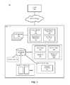
- FIG. 1is a block diagram of an embodiment of an environment with bulk delete capability for a multitenant database.
- Environment 100allows on-demand database services to client 110 from MTS 130 over network 120 .
- Client 110represents any type of user device or client device, such as any type of computing device (e.g., desktop, laptop, handheld, mobile phones or other mobile devices), through which a user client accesses MTS 130 .
- Network 120includes any form of network through which the client device of client 110 can access remote MTS 130 .
- Network 120includes transmission hardware and lines, processing equipment, and appropriate software systems as is understood in the art.
- MTS 130represents a remote database system that provides on-demand database service to client 110 .
- Application (app) server 132represents a server of MTS 130 , and may receive and process queries and/or delete requests from client 110 . It will be understood that application server 132 could be one of many (e.g., a pool or a coordinated group of) application servers.
- Application server 132processes the delete requests discussed herein, including executing the delete operations. In one embodiment, more than one application server 132 executes delete operations for a single delete request, and may all, for example, reference the same delete job to associate the operations with the delete job that satisfies the delete request.
- Database 134includes the hardware storage resources, and software components that execute on processing resources to enable access to the data.
- a databasemay be considered a structured approach to storing and accessing data stored in storage resources (such as implementing a relational model, object oriented model, or an object-relational model for data storage).
- storage resourcessuch as implementing a relational model, object oriented model, or an object-relational model for data storage.
- the database systemincludes the storage and processing resources, including interface hardware and software (such as physical network connections, network protocol stacks, security elements, and other components for interfacing with the stored data).
- the elements within the dashed box connected to application server 132represent elements that may be part of application server 132 .
- the various elements in the respective dashed boxes connected to database 134represent elements that may be part of database 134 . It will be understood that other elements could be used, and the elements shown represent functionality that may be implemented in the application server or the database of MTS 130 .
- applications server 132includes bulk delete API (application program interface) 142 , registration process 144 , execution process 146 , and physical delete process 148 .
- bulk delete APIapplication program interface
- API 142represents a callable mechanism that a user of client 110 can invoke (either manually or through an application executing on client 110 or on MTS 130 ) to implement a bulk delete.
- the bulk deleteis described herein as a mechanism that allows the user to specify (e.g., in a file with the request) multiple entries or records to be deleted.
- API 142is available via a web service to client 110 .
- client 110may access MTS 130 via a browser and generate delete requests through a web service triggers API 142 within MTS 130 .
- invoking API 142is a protected operation.
- a user profile perm(configuration value) identifies which users within a company can use the API.
- Users within a companyare users associated within a tenant ID within MTS 130 .
- the configuration valuemay be off by default, and should be enabled to allow a user profile to include access to the API.
- registration process 144registers a delete job with scheduler 180 of database 134 .
- Scheduler 180provides scheduling services for operations executed on database 134 .
- Registering a process with scheduler 180provides an identifier to recognize an individual job with the scheduler.
- registering a delete joballows MTS 130 to split the job into multiple batch jobs, and potentially across multiple application servers 132 , all associated with the registered delete job.
- multiple batch deletes, each implementing a delete operation for one or more entriescan all execute tinder a single registered delete job
- Execution process 146represents the execution resources of application server 132 to execute one or more batch jobs to implement the delete job to respond to the bulk delete request.
- application server 132includes physical delete process 148 separate from other delete processes used to respond to user requests.
- a usermay request a delete, but not have any direct access to physical delete 148 . Rather, physical delete 148 could be completely controlled by the system.
- Physical delete 148can be executed in response to execution of a requested delete, or could simply be run on a schedule.
- physical delete 148is a process to make hardware resources available within MTS 130 .
- Soft deletemarks entries as deleted, but they are still accessible and could be undeleted.
- Hard deleteprevents undeletion, and removes the entries from a filesystem or registry of the database.
- Physical delete 148reallocates physical storage resources that are available.
- database 134includes job table 152 , which represents a table of pending jobs that request access to the database.
- Job table 152may be limited to registered jobs, whereas pending access requests are placed in an execution queue.
- batch table 154allows database 134 to monitor and manage batch jobs, and associate the results of the batch jobs back to any jobs of job table 152 that they may be associated with.
- Results 156represent delete results generated by delete jobs and batch jobs executed within database 134 . As discussed above, results can be combined for the various batch jobs and sent to indicate the complete delete job results. Thus, results can be generated and stored for each batch job until the entire delete job is completed.
- Message queue 158represents any mechanism used to combine the results of the various related delete batch jobs created to execute the requested bulk delete. In one embodiment, multiple results are stored together and returned as a group to indicate the operations performed in response to the delete request.
- database 134includes recycle bin 160 .
- Recycle bin 160may be a virtual representation of records that are soft deleted.
- recycle bin 160is a storage of delete events that have been executed, and includes pointers to affected database entries.
- soft deleteis a default delete method in the system. Soft deleted records count towards storage space against the tenant organization, and may result in a performance hit.
- a hard deletecan be seen as a method of delete that effectively skips recycle bin 160 , and makes the specified records immediately eligible for physical delete.
- physical delete 148can clean up the deleted records the next time it runs.
- the ability to skip recycle bin 160 while deleting a large amount of data using a bulk delete API 142may provide a more efficient, better user experience.
- the events in the recycle binexpire after 45 days; but it will be understood that other intervals may also or alternatively be supported.
- the deleted recordswhen physical delete 148 runs, it checks whether the deleted records have an event in recycle bin 160 or not. If no event is found in the recycle bin, the deleted records are physically deleted. Thus, in one embodiment, soft deleted records would normally stay in database 134 for 45+ days (the 45 days being the time to expire, and the ‘+’ being the time until the physical delete process runs the next time after expiration of the records).
- recycle bin 160is implemented more “virtually”, with each entry or record including a field that indicates its status as soft deleted or hard deleted.
- a recycle bin storagemay not be required, and the physical delete executes as a database process in the background, such as a garbage collector or crawler.
- database 134consists of multiple object tables 170 , which include the records or entries discussed herein.
- recycle bin 160includes delete pointers 162 , which represent delete “events” pointing to specific elements of object tables 170 . Delete pointers 162 could also point to elements of database 134 even assuming the storage was not organized as object tables 170 .
- a bulk delete API as described hereinhas a different architecture compared to previous delete mechanisms, storing a job, and asynchronously executing it in pieces as resources become available.
- a userprovides the multiple identified records or entries for deletion in a CSV (character-separated value) file or XML (extensible markup language) file.
- the individual batch jobscan delete a portion of the IDs specified in such a request file.
- bulk delete APIscan be provided for either ‘soft’ delete, ‘hard’ delete, or both. Stated simply, soft delete leaves the record in the database, and allows for a process to ‘undelete’ a deleted entry. Hard delete, by contrast, does not allow undelete.
- Different mechanisms for soft deletecan be performed, including but not limited to creating a deleted pointer, moving the records to a specific location, changing a field within an entry to indicate the record is deleted, or some other mechanism.
- hard deletedoes not itself remove content, but merely flags entries for deletion.
- a system with a soft delete processalso includes a physical delete process.
- Physical deleterefers to operations on the storage space to removing the data from the system, which frees up the storage space previously occupied by the entry.
- Hard deletecan be implemented as a physical delete process, or as a process that marks entries for removal by the physical delete process the next time it is run.
- a soft deleted entrymay be valid for a threshold amount of time (e.g., 45 days, 90 days) prior to being invalid and physically deleted from the system, and a hard deleted entry is invalid immediately.
- hard deletemay not make the delete operation itself any faster. Rather, the hard delete allows saving on storage space and avoid future performance degradation from large amounts of soft deleted data.
- a bulk delete API operationis very fast compared to other API operations.
- the database systemload balances among multiple application servers to implement the multiple batch jobs. Use of a single delete job does not allow such load balancing. The use of multiple servers can further increase the speed of the bulk delete operation, assuming resources are available among multiple application servers.
- a bulk delete querycan be stored and acknowledged synchronously, while generating and executing batch jobs is asynchronous with respect to the query. Additionally, providing results to the client to indicate the state of the bulk delete operation cannot be synchronous with respect to the request if the execution of operations to produce the results is asynchronous.
- a clientpolls the database system to request results. For example, a request acknowledgement could return a handle or other identifier that will be used by the client to request results of the bulk delete. Alternatively, the database system can push the results to the client, either based on a schedule, as each batch job finishes, or when the entire delete job is completed.
- FIG. 2is a swim lane diagram of an embodiment of a delete request with asynchronous execution.
- Client 202makes a bulk delete request, which is received and processed by application server 204 , and executed on database 206 . It will be observed that certain operation blocks in FIG. 2 are dashed, while others are solid. The solid line blocks represent operations that are executed asynchronously in response to a delete request from client 202 . The dashed line blocks indicate synchronous exchanges.
- Client 202requests a delete, 210 , for example, through a bulk delete available over a web services connection with a database system.
- the delete requestidentifies the database entries for deletion, as well as a tenant identifier associated with client 202 .
- Application server 204receives the request and generates a delete job for the request, 212 .
- the delete job createdis for deletion of all entries identified in the delete request.
- Application server 204acknowledges the request synchronously, 214 , for example by sending an acknowledgement response to client 202 . While the request may be received and acknowledged synchronously, the execution of the delete is asynchronous. In one embodiment, application server 204 registers the generated delete job with a database scheduler, 216 . Database 206 through its scheduler may then register the job for scheduling, 218 . As shown above with respect to FIG. 1 , the database may enter the job in a job table.
- the application serverfurther creates multiple batch jobs, 220 , to execute the delete job.
- each batch jobis identified to database 206 , which creates a table for each batch job, 222 .
- the tablecan provide a process space for the batch job, as well as a space to store results.
- Application server 204executes the batch jobs, 224 . The execution may be performed across multiple application server instances, each referencing a corresponding batch job and table.
- the executed operationsare sent to database 206 , which enters the operations in an operation queue, 226 .
- Delete operationsmay result in marking a ‘deleted’ field as being deleted (e.g., setting a bit to ‘1’).
- database 206generates a delete pointer for each deleted entry, and adds an entry in a recycle bin, 228 .
- the databasesets a delete pointer expiration, 230 , for the created delete pointers.
- Each batch job resultsis stored, 232 , and the results are reported, 234 , to application server 204 . The results may be pushed or requested.
- client 202may request status of the delete job.
- client 202may poll the application server (the MTS) for delete request results, 236 .
- the application servercould then return any known results, 238 , to the client. The polling and responding can continue until the delete job is completed.
- FIG. 3represents a flow diagram of an embodiment of execution of a physical delete process.
- Flow diagrams as illustrated hereinprovide examples of sequences of various process actions. Although shown in a particular sequence or order, unless otherwise specified, the order of the actions can be modified. Thus, the illustrated implementations should be understood only as an example, and the process can be performed in a different order, and some actions may be performed in parallel. Additionally, one or more actions can be omitted in various embodiments; thus, not all actions are required in every implementation. Other process flows are possible.
- physical deletemay be a process that is executed separately from soft or hard delete.
- the systemdetermines to execute the physical delete process, 302 .
- Such a determination to execute the physical delete processcould be made in response to timing (e.g., a scheduled process), in conjunction with or in response to execution of a soft or hard delete process, or in response to a request by an administrator.
- the physical delete processmay be executed as one or more jobs, 304 , on one or more application servers.
- the physical delete processmay be a process owned by control logic of the database itself.
- the physical delete processaccesses a database entry, 306 , and determines if the entry is marked for delete, 308 . The determination may include checking a recycle bin for a delete event in the case where a recycle bin is implemented.
- the systemdetermines if the entry is the last entry to access for the process, 316 , and if not, it moves to the next entry and access the next database entry, 306 . If the entry is the last entry, 316 , the system completes the physical delete process, 318 , and awaits the next time the process should be executed again.
- the systemremoves the entry from the database, 312 (i.e., it physically deletes the entry), and generates a delete result, 314 . It is possible that for some reason or other the deletion of the entry does not complete successfully, in which case the result would indicate the failure of the delete instead of the successful deletion.
- the resultsmay be pushed to another process, or simply stored to await a request for the results.
- the systemcan then determine if the entry is the last entry to check for physical deletion, 316 , and either move to the next entry, 306 , or complete the process, 318 .
- FIG. 4is a block diagram of an embodiment of an environment for on-demand database services.
- Environment 400includes components related to an on-demand database service.
- Environment 400includes multitenant database system (MTS) 440 and one or more organizations 410 and 420 , which are tenants of the MTS.
- MTSmultitenant database system
- Each organizationcan include one or more users and/or user devices.
- MTS 440provides on-demand database services for environment 400 .
- An on-demand database servicesuch provided by MTS 440 , is a database system that is made available to an outside user as needed by the user (e.g., on the demand of the user).
- a userdoes not necessarily need to be concerned with building and/or maintaining the database system, and rather can simply store and access data as needed from a remotely operated database system.
- MTS 440stores information from one or more tenants into tables of a common database image or multitenant database (MTDB) 450 . Accordingly, MTS 440 provides on-demand database service.
- a database imagemay include one or more database objects.
- a multitenant databasestores data for various different tenants or organizations in a single database instance. Resources (such as memory, processing space, processing hardware, and other resources of the database system) are shared or allocated among the different tenants.
- Multitenant database 450includes tenant data 452 , . . . , 454 .
- the tenant datamay be divided into different storage areas, which can be a physical and/or a logical arrangement of data.
- multitenant database 450is accessed via a relational database management system (RDBMS) or the equivalent, which executes storage and retrieval of information against the database object(s).
- RDBMSrelational database management system
- multitenant database 450is accessed via an object-oriented database management system (OODBMS) or the equivalent.
- OODBMSobject-oriented database management system
- multitenant database 450is accessed via an Object-relational database management system (ORDBMS) or the equivalent.
- an RDBMSmanages data stored in the database based on a relational model, where data and data relationships are stored in tables.
- An OODBMSincludes at least some integration of a database with an object-oriented programming language, and data is stored in the database in the same mode of representation as is provided in the programming language.
- An ORDBMSimplements both a relational model and an object-oriented model, storing data in tables, and allowing representation of data consistent with a programming language.
- Application platform 448represents a framework that allows applications of MTS 440 to execute.
- application platform 448includes the software components (such as an operating system) to allow execution of the applications.
- Hardware platform 460provides hardware resources to enable the applications to execute on application platform 448 , as well as enabling execution of management or control logic for MTS 440 .
- application platform 448 of MTS 440enables creation, managing, and executing one or more applications developed by the provider of the on-demand database service, users accessing the on-demand database service via network 430 , or third party application developers accessing the on-demand database service via network 430 .
- MTS 440represents any type of system that may provide on-demand database service.
- MTS 440may include other components.
- MTS 440includes network interface 442 to enable user devices to access MTS 440 over network 430 .
- MTS 440includes system data 444 , program code 446 , and process space 449 .
- System data 444represents data specific to the running of MTS 440 , rather than being tenant data. It is logically separated from the tenant storage, and may be physically separated (e.g., by designating storage areas or address ranges for system data).
- Program code 446represents code to implement various functions of MTS 440 , which enable the system to provide on-demand database service.
- Process space 449represents a framework for executing MTS processes and tenant-specific processes, such as running applications as part of an application hosting service. Additional processes that may execute on MTS 440 include database indexing processes. It will be understood that MTS 440 may include more or fewer components than what is illustrated.
- environment 400includes organizations 410 and 420 , which represent tenants of MTS 440 .
- Each organizationmay include one or more individual, and may be an individual or small company, up to a large corporation or organization. Thus, it will be understood that the number of user devices associated with each organization could potentially be hundreds or even thousands.
- Each organizationis assigned a tenant identifier (ID) within MTS 440 . Each tenant ID could have certain associated properties for use, depending on how the organization is configured.
- User device 422is associated with organization 420 , and access MTS 440 under the tenant ID of organization 420 .
- user devices 412 and 416are associated with organization 410 , and access MTS 440 under the tenants ID assigned to organization 410 .
- User devices 412 , 416 , and 422may be any machine or system that is used by a user to access a database user system.
- any of the user devicescan be a handheld computing device, a mobile phone, a laptop computer, a work station, and/or a network of computing devices.
- Each user devicecan be provided with an on-demand database service from MTS 440 via network 430 .
- usersmay be further given access privileges and/or restrictions, as illustrated by data filter 414 .
- user device 416may access MTS 440 in accordance with whatever access is available to organization 410 , while user device 412 has additional restrictions applied by data filter 414 .
- data filter 414may additionally or alternatively provide specific user interface features for user 412 in accessing data from MTS 440 .
- the users of user devices 412 , 416 , and 422may differ in their respective capacities, and the capacity of a particular user device might be entirely determined by permissions (permission levels) for the current user. For example, where a salesperson is using a particular user device to interact with MTS 440 , that user device has the capacities assigned to that salesperson. However, an administrator using the same user device may have different capacities assigned to that administrator. In systems with a hierarchical role model, users at one permission level may have access to applications, data, and database information accessible by a lower permission level user, but may not have access to certain applications, database information, and data accessible by a user at a higher permission level.
- Network 430represents any network or combination of networks.
- a networkis generically an interconnection of devices that communicate with each other.
- Network 430can be or include any combination of a LAN (local area network), WAN (wide area network), telephone network, wireless network, point-to-point network, star network, token ring network, hub network, or other appropriate configuration.
- TCP/IP (Transfer Control Protocol and Internet Protocol) networksare commonly used, such as the global internetwork of networks often referred to as the “Internet.” Reference to specific networks in certain examples herein is meant only to provide examples, and is not limiting.
- user devices 412 , 416 , 422communicate with MTS 440 over network 430 using TCP/IP and, at a higher network level, use other common protocols to communicate, such as HTTP (HyperText Transfer Protocol), FTP (File Transfer Protocol), AFS (Andrew File System—a distributed network filesystem using trusted servers), WAP (Wireless Access Protocol).
- HTTPHyperText Transfer Protocol
- FTPFile Transfer Protocol
- AFSAndrew File System—a distributed network filesystem using trusted servers
- WAPWireless Access Protocol
- user device 412might include an HTTP client commonly referred to as a “browser” for sending and receiving HTTP messages to and from an HTTP server at MTS 440 (not specifically shown, but which could be executed on hardware platform 460 ).
- Such an HTTP servermight be implemented as the sole network interface between MTS 440 and network 430 , but other techniques might be used as well or instead.
- the interface between MTS 440 and network 430includes load sharing functionality, such as round-robin HTTP request distributors to balance loads and distribute incoming HTTP requests evenly over a plurality of servers. At least as for the users that are accessing that server, each of the plurality of servers has access to data in MTS 440 ; however, other alternative configurations may be used instead.
- MTS 440implements a web-based customer relationship management (CRM) system.
- MTS 440includes application servers configured to implement and execute CRM software applications as well as provide related data, code, forms, webpages and other information to and from user devices (e.g., 412 , 416 , 422 ) and to store to and retrieve from a database system related data, objects, and webpage content.
- CRMcustomer relationship management
- data for multiple tenantsmay be stored in the same physical database object; however, tenant data is typically arranged so that data of one tenant is kept logically separate from that of other tenants. The logical separation prevents one tenant from having access to another tenant's data. An express sharing of data among tenants is possible, which removes the logical separation.
- MTS 440implements applications other than or in addition to a CRM application.
- MTS 440may provide tenant access to multiple hosted (standard and custom) applications, including CRM application.
- User (or third party developer) applicationswhich may or may not include CRM, may be supported by application platform 448 , which manages creation, storage of the applications into one or more database objects and executing of the applications in a virtual machine in process space 449 of MTS 440 .
- MTS 440is configured to provide webpages, forms, applications, data and media content to user (client) device to support the access by user devices as tenants of MTS 440 .
- MTS 440provides security mechanisms to keep each tenant's data separate unless the data is shared. More than one MTS may be used. If more than one MTS is used, the multiple systems may be located in close proximity to one another (e.g., in a server farm located in a single building or campus), or they may be distributed at locations remote from one another (e.g., one or more servers located in city A and one or more servers located in city B).
- each MTScould include one or more logically and/or physically connected servers distributed locally or across one or more geographic locations.
- serverrefers to a computer system, including processing hardware and process space(s), and an associated storage system and database application (e.g., OODBMS, RDBMS, ORDBMS) as is known in the art. It will be understood that “server system” and “server” are often used interchangeably herein.
- a database object described hereincan be implemented as single databases, a distributed database, a collection of distributed databases, a database with redundant online or offline backups or other redundancies, and might include a distributed database or storage network and associated processing intelligence or logic.
- multitenant database 450includes recycle bin 456 and/or scheduler 458 .
- Recycle bin 456can enable multitenant database 450 to generate and store delete events for specified entries to be deleted.
- Soft deleted entriesare maintained “alive” in the database via recycle bin 456 until their delete events expire. Hard deleted events do not need entries in the recycle bin, since they are marked for immediate deletion.
- Scheduler 458represents any mechanism used within the multitenant database to control the execution of operations within multitenant database 450 .
- Scheduler 458may thus access contract or restrictions for the tenants to determine how to allocate resources among the tenants.
- a delete requestis broken into multiple operations, which can be scheduled separately, and in accordance with the proportional scheduling for the tenant they belong to.
- FIG. 5is a block diagram of an embodiment of an environment for on-demand database services with a multitenant database having multiple data tables.
- Environment 500includes components related to providing an on-demand database service, and may be one example of environment 400 of FIG. 4 , with additional components shown.
- Environment 500includes one or more multitenant database systems (MTS) 540 and one or more tenants of the MTS, as illustrated by user device 510 .
- MTSmultitenant database systems
- User device 510is generally part of an organization that is the tenant, and user device 510 provides a computing device through which access to MTS 540 is available.
- MTS 540provides on-demand database services for environment 500 .
- Environment 500may include conventional, well-known elements that are explained only briefly here.
- user device 510and any other user devices through which users access MTS 540 ) could include a desktop personal computer, workstation, laptop, handheld device, cell phone or smart phone, or any wireless access protocol (WAP) enabled device or any other computing device capable of interfacing directly or indirectly to the Internet or other network connection.
- WAPwireless access protocol
- User device 510includes processor 512 , which represents one or more processor devices, and may be any combination of one or more processors.
- Processor 512provides hardware means to execute programs and applications on user device 510 .
- Memory 514represents a memory system for user device 510 , and may be any combination of one or more memory devices, short term, and/or tong term memory.
- I/O (input/output) 516represents any type of input and output devices such as keyboards, pointers and controllers, touchscreens, buttons, microphones, or other input mechanisms, and monitors, screens, printers, interfaces to networks, and/or other output devices.
- User device 510includes network interface 518 , which represents hardware interconnections and control logic and circuitry to enable user device 510 to connect to network 530 .
- Network interface 518also has associated drivers and possibly other software components to allow user programs to interface with the interconnection hardware.
- User device 510includes client 520 , which represents a program that allows a user of user device 510 to access information from network 530 , such as accessing MTS 540 .
- UI 522represents a user interface component of client 520 , or a user interface in which information from client 520 is presented on user device 510 . Thus, UI 522 may be integrated with client 520 , or it may be separate from client 520 , but display data related to the execution of client 520 .
- UI 522is rendered on display or user interface hardware or device, which can be understood to be represented by UI 522 .
- user device 510runs an HTTP client as client 520 .
- An HTTP clientmay be, for example, a browsing program or a browser, which may include a WAP-enabled browser in the case of a cell phone, PDA or other wireless device.
- the HTTP clientallows a user (e.g., subscriber of MTS 540 ) of user device 510 to access, process, and view information, pages, and applications available from MTS 540 over network 530 , based on permissions and privileges.
- the user interface device of user device 510can be used to access data and applications hosted by MTS 540 , and to perform searches on stored data, and otherwise allow a user to interact with various GUI (graphical user interface) pages that may be presented to a user.
- GUIgraphical user interface
- network 530represents any network or group of networks over which access can be provided to MTS 540 .
- Network 530may include switching and/or routing elements, cables, connectors, and other components.
- at least part of network 530is the Internet, referring to a specific internetwork of networks.
- other networkscan be used in addition to or instead of the Internet, such as an intranet, an extranet, a virtual private network (VPN), a non-TCP/IP based network, any LAN or WAN or other network.
- VPNvirtual private network
- non-TCP/IP based networkany LAN or WAN or other network.
- user devicessuch as user device 510 (which may be client systems) communicate with application server 550 to request and update system-level and tenant-level data from MTS 540 that may require sending one or more queries to tenant data storage in database instance 580 and/or system data in system database 542 .
- MTS 540e.g., application server 550
- MTS 540automatically generates one or more SQL statements (e.g., one or more SQL queries) designed to access the desired information.
- System data storage in system database 542may generate query plans to access the requested data from database instance 580 .
- MTS 540includes one or more application servers 550 .
- application server 550can be considered a network interface of MTS 540 to connect to network 530 .
- Application server 550exchanges (i.e., receives and/or transmits) data with network 530 , such as receiving requests and sending replies or sending data.
- Application servers 550may share hardware resources for interfacing with network 530 , or they may be assigned separate resources.
- one or more of application servers 550can be implemented as an HTTP application server.
- each application server 550is configured to handle requests for any user associated with any organization that is a tenant. Thus, a request from user device 510 could be received and processed at any application server 550 .
- an application servercould not be removed without completing its jobs and/or handing off users to another server.
- an interface system implementing a load balancing function(e.g., an F5 Big-IP load balancer) is communicably coupled between application servers 550 and the user devices to distribute requests to the application servers 550 .
- the load balanceruses a least connections algorithm to route user requests to the application servers 550 .
- Other examples of load balancing algorithmssuch as round robin and observed response time, also can be used. For example, in certain embodiments, three consecutive requests from the same user could hit three different application servers 550 , and three requests from different users could hit the same application server 550 .
- MTS 540is multitenant, wherein MTS 540 handles storage of, and access to, different objects, data, and applications across disparate users and organizations.
- MTS 540is multitenant, wherein MTS 540 handles storage of, and access to, different objects, data, and applications across disparate users and organizations.
- Each application server 550includes elements to provide database access service and request processing.
- Application server 550includes API (application programming interface) 552 and UI 554 .
- UI 554represents server-side components that provide user interface elements that are provided to user device 510 for display.
- API 552provides an interface for users and/or developers to access resident processes of MTS 540 .
- application server 550includes application (appl) platform 560 , which provides a sub-environment on which applications hosted by application server 550 can be executed.
- Application platform 560may include an operating system or other control logic, as well as business logic and common routines for use by the applications.
- application platform 560includes application setup mechanism 562 that supports creation and management of applications, including configuration, by application developers, which may be saved as metadata into tenant data storage of database (db) instance 580 .
- Save routines 564represent the mechanisms used to store data in database instance 580 , such as storing the application setup metadata.
- Such applicationscan be executed by subscriber users, for example, in process space 570 .
- invocations to or related to such applicationsmay be coded using PL/SOQL (Procedural Language Salesforce Object Query Language) that provides a programming language style interface extension to API 552 .
- PL/SOQL 566is capable of serving as a procedural extension to an on-demand database centric service API that allows flow control and transaction control to execute on a server in conjunction with database APIs (e.g., SOQL, data manipulation language (DML), or others).
- database APIse.g., SOQL, data manipulation language (DML), or others.
- PL/SOQL 566can enable the capability to thread together multiple SOQL/DML statements as a single unit of work on the server.
- PL/SOQL 566need not necessarily be considered a general purpose programming language, seeing that it may be implemented as heavily data focused, but is not necessarily implemented that way.
- PL/SOQL 566can be used by developers to interlace with an on-demand database system, in contrast to traditional application developers' conventional tools, such as PL/SQL (Structured Query Language) of ORACLE, Inc. of Redwood Shores, Calif., and others.
- PL/SQLStructured Query Language
- PL/SOQL 566includes variable and expression syntax, block and conditional syntax, loop syntax, object and array notation, pass by reference, and other syntax known to other programming languages.
- variable and expression syntaxblock and conditional syntax, loop syntax, object and array notation, pass by reference, and other syntax known to other programming languages.
- syntax and semanticsthat are easy to understand and which encourage efficient use of database APIs may also be employed.
- PL/SOQL 566is implemented as a strong typed language with direct (non-quoted) references to schema objects such as Object and Field names (both standard and custom).
- invocations to applicationsmay be detected by one or more system processes, which manage retrieving application metadata 586 for the subscriber making the invocation and executing the metadata as an application in a virtual machine.
- Metadata 586provides data related to access and/or use of data stored in database instance 580 .
- metadatais stored in a separate table within database instance 580 , and in an alternative embodiment, metadata 586 is stored with other data elements of user storage (such as with user storage 584 of table 582 - 0 .
- application server 550includes process space 570 , which may include tenant process spaces 576 - 0 through 576 -N (for some integer number N of process spaces configured in application server 550 ), tenant management process space 572 and system process space 574 .
- process space 570is an abstraction to illustrate the resources allocated for execution of processes (e.g., programs or applications) within application server 550 .
- the skilled readerrecognizes that memory and processor and other hardware resources may need to be allocated, as well as software resources to support the execution of a process.
- the processesmay be executed as separate threads, or may share a thread, in one embodiment, the number N of tenant processes is equal to a number of subscriber tenants. In another embodiment, the number N of tenant processes may be higher than the number of subscriber tenants.
- Tenant management process 572provides management of the other processes, including determining when certain processes execute.
- System process 574executes operations related to functions of MTS 540 .
- Each application server 550may be configured to tenant data storage in database instance 580 and the tenant data stored therein, and to system data storage of system database 542 and the system data stored therein to serve requests of user devices.
- tenant datais separated logically, and stored in the same multitenant database.
- database instance 580stores data in tables 582 - 0 through 582 -M, where M is some integer number of tables.
- different tablesstore data of different types.
- Application metadata 586may be implemented as a separate table.
- one of the tables 582 - 0 through 582 -Mcould be a table that stores varying types of objects, which are defined through metadata stored in the table.
- database instanceis further implemented with user storage space distinct (e.g., identifiable) from its associated tenant.
- user datamay include the tenant ID, as well as an identifier specific to a user.
- storage 584may represent either or both of tenant storage or user storage.
- a copy of a user's most recently used (MRU) itemsmight be stored to in user storage within database instance 580 .
- MRUmost recently used
- a copy of MRU items for an entire organization that is a tenantmight be stored to a tenant storage area of database instance 580 .
- the tenant data and the system dataare stored in separate databases.
- Application servers 550may be communicably coupled to database systems, e.g., having access to system database 542 and tenant database instance 580 , via a different network connection.
- database systemse.g., having access to system database 542 and tenant database instance 580
- one application servermay be coupled via a network (e.g., the Internet)
- another application servermight be coupled via a direct network link
- another application servermight be coupled by yet a different network connection.
- the application serversmay connect to the database systems via TCP/IP or another transport protocol, at least partially depending on the network interconnect used.
- one tenantmight be a company that employs a sales force where each salesperson uses MTS 540 to manage their sales process.
- a usermight maintain contact data, leads data, customer follow-up data, performance data, goals and progress data, and other data, all applicable to that user's personal sales process (e.g., storage 584 , which may be tenant storage).
- storage 584which may be tenant storage.
- all of the data and the applications to access, view, modify, report, transmit, calculate, or perform other operationscan be maintained and accessed via a user device having nothing more than network access.
- the usercan manage his or her sales efforts and cycles from any of many different user devices. For example, if a salesperson is visiting a customer and the customer has a lobby with Internet access, the salesperson can obtain critical updates as to that customer while waiting for the customer to arrive in the lobby.
- MTS 540While each user's data might be separate from other users' data regardless of the employers of each user, some data might be organization-wide data shared or accessible by a plurality of users or all of the users for a given organization that is a tenant. Thus, there might be some data structures managed by MTS 540 that are allocated at the tenant level while other data structures might be managed at the user level. Because MTS 540 may support multiple tenants including possible competitors, MTS 540 should have security protocols that keep data, applications, and application use separate. Additionally, because many tenants may opt for access to an MTS rather than maintain their own system, redundancy, up-time, and backup are additional functions that may be implemented MTS 540 . In addition to user-specific data and tenant specific data, MTS 540 may also maintain system level data usable by multiple tenants or other data. Such system level data might include industry reports, news, postings, and the like that are sharable among tenants.
- each database instance 580can be viewed as a collection of objects, such as a set of logical tables, containing data fitted into predefined categories,
- a “table”is one representation of a data object, and may be used herein to simplify the conceptual description of objects and custom objects according to what is described herein. It should be understood that “table” and “object type” may be used interchangeably herein.
- Each tablegenerally contains one or more data categories logically arranged as columns or fields in a viewable schema. Each row or record of a table contains an instance of data for each category defined by the fields.
- a CRM databasemay include a table that describes a customer with fields for basic contact information such as name, address, phone number, fax number, or other information. Another table might describe a purchase order, including fields for information such as customer, product, sale price, date, or other fields.
- a multitenant databasehas standard entity tables for use by all tenants. For CRM database applications, such standard entities might include tables for Account, Contact, Lead, and Opportunity data, each containing pre-defined fields. Thus, tables 582 - 0 through 582 -M may include standard, defined tables.
- tenantsmay be allowed to create and store custom objects, or they may be allowed to customize standard entities or objects, for example by creating custom fields for standard objects, including custom index fields.
- U.S. patent application Ser. No. 10/817,161, filed Apr. 2, 2004, entitled “Custom Entities and Fields in a Multi-Tenant Database System”teaches systems and methods for creating custom objects as well as customizing standard objects in a multitenant database system.
- all custom entity data rowsare stored in a single multitenant physical table, which may contain multiple tables per organization. It is transparent to customers that their multiple “tables” are in fact stored in one large table or that their data may be stored in the same table as the data of other customers.
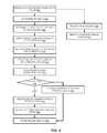
- FIG. 6represents a flow diagram of an embodiment of bulk delete with hard or soft delete processes in a multitenant database.
- Flow diagrams as illustrated hereinprovide examples of sequences of various process actions. Although shown in a particular sequence or order, unless otherwise specified, the order of the actions can be modified. Thus, the illustrated implementations should be understood only as an example, and the process can be performed in a different order, and some actions may be performed in parallel. Additionally, one or more actions can be omitted in various embodiments; thus, not all actions are required in every implementation. Other process flows are possible.
- a server of a multitenant database systemreceives a bulk delete request from a client over a network via a delete API, 602 .
- the servermay respond synchronously to the request, and then execute the request asynchronously.
- the serverdetermines a tenant ID associated with the request, 604 .
- the tenant IDmay be a part of every request, or it may be determined by referencing the client ID of the requestor.
- the serverdetermines if soft delete or hard delete is requested, 606 .
- the two different types of deleteare identified by separate APIs.
- the type of deleteis identified by the request.
- the systemdetermines from the request or otherwise what type of delete will be implemented. Except where identified, the following operations apply to both hard and soft delete.
- the servercreates a delete job in response to the delete request, 608 .
- the delete jobhas associated with it all the records for which delete are requested in the bulk delete request received.
- the delete jobis registered with the multitenant database for scheduling, 610 .
- the servercreates multiple batch jobs to implement the delete job, 612 .
- the size of the batch jobsis predetermined, for example, to delete a certain number (e.g., 50, 100, 200) of records at a time.
- the servercan simply divide the delete job into batch jobs based on the number of records for which delete is requested. More sophisticated algorithms could be used, for example, by considering a total number of records requested to be deleted, and dividing the delete job into 10 batch jobs for a certain range, 20 for a next range of deletes, and so forth. It will be understood that more complicated algorithms required additional logic to execute.
- the server or servers selected for execution of the batch jobsexecuted the batch jobs asynchronously with respect to the request, 614 .
- the execution of the batch jobsdepends upon the delete type. If the delete type is a hard delete, 616 , then a hard delete process is executed. It will be understood that a single request will be for hard delete or soft delete of all records identified—there is not a request that performs hard delete on certain records and soft delete on others. For hard delete, in one embodiment, the identified records are set for delete to be eliminated by the next execution of a physical delete process, 618 .
- the databasecreates a delete pointer for each deleted entry, 620 .
- the databasesets a delete timer for each deleted entry, 622 .
- the delete timermay be a timestamp of the time of creation of a delete event, or a time value stored and associated with the record to which it corresponds.
- the databasestores the results of each delete operation, 624 .
- the resultscan be passed back to the client to indicate progress of the delete job.
- a clientcan poll the MTS for status of the delete job (by identifying the delete request that it sent, or identifying the delete job via an identifier sent in a synchronous acknowledgement).
- the serverreceives a poll request from the client, 630 .
- the serverreports any known delete results to the client in response to the request, 632 .
- the serverreceives the results from the database and can then pass them to the client.
- the contentmay be directly executable (“object” or “executable” form), source code, or difference code (“delta” or “patch” code).
- the software content of the embodiments described hereinmay be provided via an article of manufacture with the content stored thereon, or via a method of operating a communications interface to send data via the communications interface.
- a machine readable medium or computer readable mediummay cause a machine to perform the functions or operations described, and includes any mechanism that provides (i.e., stores and/or transmits) information in a form accessible by a machine (e.g., computing device, electronic system, or other device), such as via recordable/non-recordable storage media (e.g., read only memory (ROM), random access memory (RAM), magnetic disk storage media, optical storage media, flash memory devices, or other storage media) or via transmission media (e.g., optical, digital, electrical, acoustic signals or other propagated signal).
- ROMread only memory
- RAMrandom access memory
- transmission mediae.g., optical, digital, electrical, acoustic signals or other propagated signal.
- a communication interfaceincludes any mechanism that interfaces to any of a hardwired, wireless, optical, or other medium to communicate to another device, such as a memory bus interface, a processor bus interface, an Internet connection, a disk controller.
- the communication interfacecan be configured by providing configuration parameters and/or sending signals to prepare the communication interface to provide a data signal describing the software content.
- Each component described hereinmay be a means for performing the operations or functions described.
- Each component described hereinincludes software, hardware, or a combination of these.
- the componentscan be implemented as software modules, hardware modules, special-purpose hardware (e.g., application specific hardware, application specific integrated circuits (ASICs), digital signal processors (DSPs), etc.), embedded controllers, hardwired circuitry, etc.
- special-purpose hardwaree.g., application specific hardware, application specific integrated circuits (ASICs), digital signal processors (DSPs), etc.
- embedded controllerse.g., hardwired circuitry, etc.
Landscapes
- Engineering & Computer Science (AREA)
- Databases & Information Systems (AREA)
- Theoretical Computer Science (AREA)
- Data Mining & Analysis (AREA)
- Physics & Mathematics (AREA)
- General Engineering & Computer Science (AREA)
- General Physics & Mathematics (AREA)
- Computing Systems (AREA)
- Information Retrieval, Db Structures And Fs Structures Therefor (AREA)
Abstract
Description
Claims (16)
Priority Applications (1)
| Application Number | Priority Date | Filing Date | Title |
|---|---|---|---|
| US13/094,745US8635250B2 (en) | 2010-04-26 | 2011-04-26 | Methods and systems for deleting large amounts of data from a multitenant database |
Applications Claiming Priority (2)
| Application Number | Priority Date | Filing Date | Title |
|---|---|---|---|
| US32799210P | 2010-04-26 | 2010-04-26 | |
| US13/094,745US8635250B2 (en) | 2010-04-26 | 2011-04-26 | Methods and systems for deleting large amounts of data from a multitenant database |
Publications (2)
| Publication Number | Publication Date |
|---|---|
| US20110264704A1 US20110264704A1 (en) | 2011-10-27 |
| US8635250B2true US8635250B2 (en) | 2014-01-21 |
Family
ID=44816697
Family Applications (1)
| Application Number | Title | Priority Date | Filing Date |
|---|---|---|---|
| US13/094,745Active2032-01-12US8635250B2 (en) | 2010-04-26 | 2011-04-26 | Methods and systems for deleting large amounts of data from a multitenant database |
Country Status (1)
| Country | Link |
|---|---|
| US (1) | US8635250B2 (en) |
Cited By (4)
| Publication number | Priority date | Publication date | Assignee | Title |
|---|---|---|---|---|
| US20130007062A1 (en)* | 2011-07-01 | 2013-01-03 | Salesforce.Com, Inc. | Truncating data associated with objects in a multi-tenant database |
| US20140122448A1 (en)* | 2012-10-31 | 2014-05-01 | Kabushiki Kaisha Toshiba | Information processing apparatus, information processing method and program storage medium |
| US20200327113A1 (en)* | 2012-08-08 | 2020-10-15 | Amazon Technologies, Inc. | Data storage application programming interface |
| US11244291B2 (en) | 2016-04-14 | 2022-02-08 | Advanced New Technologies Co., Ltd. | Method and system for allocating virtual articles |
Families Citing this family (20)
| Publication number | Priority date | Publication date | Assignee | Title |
|---|---|---|---|---|
| US20110265069A1 (en)* | 2010-04-21 | 2011-10-27 | Salesforce.Com | Methods and systems for execution of tenant code in an on-demand service environment including utilization of shared resources and inline governor limit enforcement |
| CN102131002B (en)* | 2011-03-29 | 2016-10-05 | 华为终端有限公司 | A kind of data in mobile phone treating method and apparatus |
| US9442974B2 (en) | 2012-09-05 | 2016-09-13 | Salesforce.Com, Inc. | Systems, methods and techniques for polymorphic queries |
| US20140067852A1 (en)* | 2012-09-06 | 2014-03-06 | salesforce.com,inc. | Mechanism for facilitating scaling and efficient management of database systems and resources in an on-demand services environment |
| US9626637B2 (en) | 2012-09-18 | 2017-04-18 | Salesforce.Com, Inc. | Method and system for managing business deals |
| CN103793777A (en)* | 2012-11-02 | 2014-05-14 | 凌群电脑股份有限公司 | Remote batch operation management system and management method thereof |
| US9553757B1 (en)* | 2013-05-21 | 2017-01-24 | Amazon Technologies, Inc. | Substitution of requests or results in access control systems |
| US9535721B2 (en)* | 2013-06-17 | 2017-01-03 | Apple Inc. | Method and apparatus for optimized bulk constraint removal with accumulation |
| US20160021196A1 (en)* | 2014-07-17 | 2016-01-21 | Microsoft Corporation | Processing changes in a multi-tenant system |
| US10531288B2 (en) | 2016-06-30 | 2020-01-07 | Intel Corporation | Data management microservice in a microservice domain |
| US10007695B1 (en) | 2017-05-22 | 2018-06-26 | Dropbox, Inc. | Replication lag-constrained deletion of data in a large-scale distributed data storage system |
| US10585698B2 (en)* | 2017-11-10 | 2020-03-10 | Salesforce.Com, Inc. | Template-driven multi-tenant workflow processing |
| US12393571B2 (en)* | 2018-12-05 | 2025-08-19 | Humana Inc. | Multidimensional multitenant system |
| CN110381121B (en)* | 2019-06-26 | 2022-03-22 | 苏州浪潮智能科技有限公司 | Data processing method and device |
| CN111144077B (en)* | 2019-12-27 | 2023-11-21 | 深圳市微购科技有限公司 | View information deleting method, device, equipment and computer readable storage medium |
| US11321007B2 (en)* | 2020-07-29 | 2022-05-03 | International Business Machines Corporation | Deletion of volumes in data storage systems |
| US11829630B2 (en)* | 2020-10-23 | 2023-11-28 | EMC IP Holding Company LLC | Synthetically providing multiple types of granular delete operations for a cloud-based object storage |
| US11860836B2 (en)* | 2020-12-29 | 2024-01-02 | Dropbox, Inc. | Object management system for efficient content item management |
| CN113867628B (en)* | 2021-09-02 | 2024-01-19 | 网易(杭州)网络有限公司 | Data deleting method, device, storage medium and computing equipment |
| CN114661240B (en)* | 2022-03-30 | 2024-12-31 | 阿里巴巴(中国)有限公司 | A data processing method and storage system |
Citations (94)
| Publication number | Priority date | Publication date | Assignee | Title |
|---|---|---|---|---|
| US5577188A (en) | 1994-05-31 | 1996-11-19 | Future Labs, Inc. | Method to provide for virtual screen overlay |
| US5608872A (en) | 1993-03-19 | 1997-03-04 | Ncr Corporation | System for allowing all remote computers to perform annotation on an image and replicating the annotated image on the respective displays of other comuters |
| US5649104A (en) | 1993-03-19 | 1997-07-15 | Ncr Corporation | System for allowing user of any computer to draw image over that generated by the host computer and replicating the drawn image to other computers |
| US5715450A (en) | 1995-09-27 | 1998-02-03 | Siebel Systems, Inc. | Method of selecting and presenting data from a database using a query language to a user of a computer system |
| US5821937A (en) | 1996-02-23 | 1998-10-13 | Netsuite Development, L.P. | Computer method for updating a network design |
| US5831610A (en) | 1996-02-23 | 1998-11-03 | Netsuite Development L.P. | Designing networks |
| US5873096A (en) | 1997-10-08 | 1999-02-16 | Siebel Systems, Inc. | Method of maintaining a network of partially replicated database system |
| US5918159A (en) | 1997-08-04 | 1999-06-29 | Fomukong; Mundi | Location reporting satellite paging system with optional blocking of location reporting |
| US5963953A (en) | 1998-03-30 | 1999-10-05 | Siebel Systems, Inc. | Method, and system for product configuration |
| US6092083A (en) | 1997-02-26 | 2000-07-18 | Siebel Systems, Inc. | Database management system which synchronizes an enterprise server and a workgroup user client using a docking agent |
| US6169534B1 (en) | 1997-06-26 | 2001-01-02 | Upshot.Com | Graphical user interface for customer information management |
| US6178425B1 (en) | 1997-02-26 | 2001-01-23 | Siebel Systems, Inc. | Method of determining the visibility to a remote database client of a plurality of database transactions using simplified visibility rules |
| US6216135B1 (en) | 1997-02-26 | 2001-04-10 | Siebel Systems, Inc. | Method of determining visibility to a remote database client of a plurality of database transactions having variable visibility strengths |
| US6233617B1 (en) | 1997-02-26 | 2001-05-15 | Siebel Systems, Inc. | Determining the visibility to a remote database client |
| US6266669B1 (en) | 1997-02-28 | 2001-07-24 | Siebel Systems, Inc. | Partially replicated distributed database with multiple levels of remote clients |
| US6295530B1 (en) | 1995-05-15 | 2001-09-25 | Andrew M. Ritchie | Internet service of differently formatted viewable data signals including commands for browser execution |
| US20010044791A1 (en) | 2000-04-14 | 2001-11-22 | Richter James Neal | Automated adaptive classification system for bayesian knowledge networks |
| US6324568B1 (en) | 1999-11-30 | 2001-11-27 | Siebel Systems, Inc. | Method and system for distributing objects over a network |
| US6324693B1 (en) | 1997-03-12 | 2001-11-27 | Siebel Systems, Inc. | Method of synchronizing independently distributed software and database schema |
| US6336137B1 (en) | 2000-03-31 | 2002-01-01 | Siebel Systems, Inc. | Web client-server system and method for incompatible page markup and presentation languages |
| US20020022986A1 (en) | 1998-11-30 | 2002-02-21 | Coker John L. | Smart scripting call centers |
| USD454139S1 (en) | 2001-02-20 | 2002-03-05 | Rightnow Technologies | Display screen for a computer |
| US20020029376A1 (en) | 1998-11-30 | 2002-03-07 | Jesse Ambrose | Development tool, method, and system for client server applications |
| US20020029161A1 (en) | 1998-11-30 | 2002-03-07 | Brodersen Robert A. | Assignment manager |
| US6367077B1 (en) | 1997-02-27 | 2002-04-02 | Siebel Systems, Inc. | Method of upgrading a software application in the presence of user modifications |
| US20020042264A1 (en) | 2000-10-11 | 2002-04-11 | Lg Electronics Inc. | Data communication method using mobile terminal |
| US6393605B1 (en) | 1998-11-18 | 2002-05-21 | Siebel Systems, Inc. | Apparatus and system for efficient delivery and deployment of an application |
| US20020072951A1 (en) | 1999-03-03 | 2002-06-13 | Michael Lee | Marketing support database management method, system and program product |
| US20020082892A1 (en) | 1998-08-27 | 2002-06-27 | Keith Raffel | Method and apparatus for network-based sales force management |
| US6434550B1 (en) | 2000-04-14 | 2002-08-13 | Rightnow Technologies, Inc. | Temporal updates of relevancy rating of retrieved information in an information search system |
| US6446089B1 (en) | 1997-02-26 | 2002-09-03 | Siebel Systems, Inc. | Method of using a cache to determine the visibility to a remote database client of a plurality of database transactions |
| US20020143997A1 (en) | 2001-03-28 | 2002-10-03 | Xiaofei Huang | Method and system for direct server synchronization with a computing device |
| US20020140731A1 (en) | 2001-03-28 | 2002-10-03 | Pavitra Subramaniam | Engine to present a user interface based on a logical structure, such as one for a customer relationship management system, across a web site |
| US20020152102A1 (en) | 1998-11-30 | 2002-10-17 | Brodersen Karen Cheung | State models for monitoring process |
| US20020161734A1 (en) | 1999-03-03 | 2002-10-31 | Christopher Stauber | Application instantiation based upon attributes and values stored in a meta data repository, including tiering of application layers objects and components |
| US20020162090A1 (en) | 2001-04-30 | 2002-10-31 | Parnell Karen P. | Polylingual simultaneous shipping of software |
| US20020165742A1 (en) | 2000-03-31 | 2002-11-07 | Mark Robins | Feature centric release manager method and system |
| US20030004971A1 (en) | 2001-06-29 | 2003-01-02 | Gong Wen G. | Automatic generation of data models and accompanying user interfaces |
| US20030018705A1 (en) | 2001-03-31 | 2003-01-23 | Mingte Chen | Media-independent communication server |
| US20030018830A1 (en) | 2001-02-06 | 2003-01-23 | Mingte Chen | Adaptive communication application programming interface |
| US6535909B1 (en) | 1999-11-18 | 2003-03-18 | Contigo Software, Inc. | System and method for record and playback of collaborative Web browsing session |
| US20030066032A1 (en) | 2001-09-28 | 2003-04-03 | Siebel Systems,Inc. | System and method for facilitating user interaction in a browser environment |
| US20030066031A1 (en) | 2001-09-28 | 2003-04-03 | Siebel Systems, Inc. | Method and system for supporting user navigation in a browser environment |
| US20030069936A1 (en) | 2001-10-09 | 2003-04-10 | Warner Douglas K. | Method for routing electronic correspondence based on the level and type of emotion contained therein |
| US20030070005A1 (en) | 2001-09-29 | 2003-04-10 | Anil Mukundan | Method, apparatus, and system for implementing view caching in a framework to support web-based applications |
| US20030070004A1 (en) | 2001-09-29 | 2003-04-10 | Anil Mukundan | Method, apparatus, and system for implementing a framework to support a web-based application |
| US20030070000A1 (en) | 2001-09-29 | 2003-04-10 | John Coker | Computing system and method to implicitly commit unsaved data for a World Wide Web application |
| US20030074418A1 (en) | 2001-09-29 | 2003-04-17 | John Coker | Method, apparatus and system for a mobile web client |
| US6560461B1 (en) | 1997-08-04 | 2003-05-06 | Mundi Fomukong | Authorized location reporting paging system |
| US20030088545A1 (en) | 2001-06-18 | 2003-05-08 | Pavitra Subramaniam | System and method to implement a persistent and dismissible search center frame |
| US6577726B1 (en) | 2000-03-31 | 2003-06-10 | Siebel Systems, Inc. | Computer telephony integration hotelling method and system |
| US6601087B1 (en) | 1998-11-18 | 2003-07-29 | Webex Communications, Inc. | Instant document sharing |
| US6604117B2 (en) | 1996-03-19 | 2003-08-05 | Siebel Systems, Inc. | Method of maintaining a network of partially replicated database system |
| US20030151633A1 (en) | 2002-02-13 | 2003-08-14 | David George | Method and system for enabling connectivity to a data system |
| US20030159136A1 (en) | 2001-09-28 | 2003-08-21 | Huang Xiao Fei | Method and system for server synchronization with a computing device |
| US6621834B1 (en) | 1999-11-05 | 2003-09-16 | Raindance Communications, Inc. | System and method for voice transmission over network protocols |
| US20030189600A1 (en) | 2002-03-29 | 2003-10-09 | Prasad Gune | Defining an approval process for requests for approval |
| US20030191743A1 (en) | 1998-03-03 | 2003-10-09 | Siebel Systems, Inc. | Method, apparatus, system, and program product for attaching files and other objects to a partially replicated database |
| US20030204427A1 (en) | 2002-03-29 | 2003-10-30 | Prasad Gune | User interface for processing requests for approval |
| US20030206192A1 (en) | 2001-03-31 | 2003-11-06 | Mingte Chen | Asynchronous message push to web browser |
| US6654032B1 (en) | 1999-12-23 | 2003-11-25 | Webex Communications, Inc. | Instant sharing of documents on a remote server |
| US20030225730A1 (en) | 2002-06-03 | 2003-12-04 | Rightnow Technologies, Inc. | System and method for generating a dynamic interface via a communications network |
| US6665655B1 (en) | 2000-04-14 | 2003-12-16 | Rightnow Technologies, Inc. | Implicit rating of retrieved information in an information search system |
| US20040001092A1 (en) | 2002-06-27 | 2004-01-01 | Rothwein Thomas M. | Prototyping graphical user interfaces |
| US20040010489A1 (en) | 2002-07-12 | 2004-01-15 | Rightnow Technologies, Inc. | Method for providing search-specific web pages in a network computing environment |
| US20040015981A1 (en) | 2002-06-27 | 2004-01-22 | Coker John L. | Efficient high-interactivity user interface for client-server applications |
| US20040027388A1 (en) | 2002-06-27 | 2004-02-12 | Eric Berg | Method and apparatus to facilitate development of a customer-specific business process model |
| US6711565B1 (en) | 2001-06-18 | 2004-03-23 | Siebel Systems, Inc. | Method, apparatus, and system for previewing search results |
| US6724399B1 (en) | 2001-09-28 | 2004-04-20 | Siebel Systems, Inc. | Methods and apparatus for enabling keyboard accelerators in applications implemented via a browser |
| US20040078370A1 (en)* | 2002-10-17 | 2004-04-22 | International Business Machines Corporation | Method and apparatus for real time creation and modification of a change log for multi-server synchronization |
| US6728702B1 (en) | 2001-06-18 | 2004-04-27 | Siebel Systems, Inc. | System and method to implement an integrated search center supporting a full-text search and query on a database |
| US6728960B1 (en) | 1998-11-18 | 2004-04-27 | Siebel Systems, Inc. | Techniques for managing multiple threads in a browser environment |
| US6732100B1 (en) | 2000-03-31 | 2004-05-04 | Siebel Systems, Inc. | Database access method and system for user role defined access |
| US6732095B1 (en) | 2001-04-13 | 2004-05-04 | Siebel Systems, Inc. | Method and apparatus for mapping between XML and relational representations |
| US20040128001A1 (en) | 2002-08-28 | 2004-07-01 | Levin Issac Stephen | Method and apparatus for an integrated process modeller |
| US6763351B1 (en) | 2001-06-18 | 2004-07-13 | Siebel Systems, Inc. | Method, apparatus, and system for attaching search results |
| US6763501B1 (en) | 2000-06-09 | 2004-07-13 | Webex Communications, Inc. | Remote document serving |
| US20040186860A1 (en) | 2003-03-21 | 2004-09-23 | Wen-Hsin Lee | Method and architecture for providing data-change alerts to external applications via a push service |
| US20040193510A1 (en) | 2003-03-25 | 2004-09-30 | Catahan Nardo B. | Modeling of order data |
| US20040199489A1 (en) | 2003-03-24 | 2004-10-07 | Barnes-Leon Maria Theresa | Custom common object |
| US20040199543A1 (en) | 2003-04-04 | 2004-10-07 | Braud Luke A. | Facilitating data manipulation in a browser-based user interface of an enterprise business application |
| US20040199536A1 (en) | 2003-03-24 | 2004-10-07 | Barnes Leon Maria Theresa | Product common object |
| US6804330B1 (en) | 2002-01-04 | 2004-10-12 | Siebel Systems, Inc. | Method and system for accessing CRM data via voice |
| US6826582B1 (en) | 2001-09-28 | 2004-11-30 | Emc Corporation | Method and system for using file systems for content management |
| US6829655B1 (en) | 2001-03-28 | 2004-12-07 | Siebel Systems, Inc. | Method and system for server synchronization with a computing device via a companion device |
| US20040249854A1 (en) | 2003-03-24 | 2004-12-09 | Barnes-Leon Maria Theresa | Common common object |
| US20040260534A1 (en) | 2003-06-19 | 2004-12-23 | Pak Wai H. | Intelligent data search |
| US20040260659A1 (en) | 2003-06-23 | 2004-12-23 | Len Chan | Function space reservation system |
| US20040268299A1 (en) | 2003-06-30 | 2004-12-30 | Shu Lei | Application user interface template with free-form layout |
| US6842748B1 (en) | 2000-04-14 | 2005-01-11 | Rightnow Technologies, Inc. | Usage based strength between related information in an information retrieval system |
| US20050050555A1 (en) | 2003-08-28 | 2005-03-03 | Exley Richard Mark | Universal application network architecture |
| US20050283478A1 (en)* | 2004-06-16 | 2005-12-22 | Salesforce.Com, Inc. | Soap-based Web services in a multi-tenant database system |
| US7340411B2 (en) | 1998-02-26 | 2008-03-04 | Cook Rachael L | System and method for generating, capturing, and managing customer lead information over a computer network |
| US7620655B2 (en) | 2003-05-07 | 2009-11-17 | Enecto Ab | Method, device and computer program product for identifying visitors of websites |
- 2011
- 2011-04-26USUS13/094,745patent/US8635250B2/enactiveActive
Patent Citations (119)
| Publication number | Priority date | Publication date | Assignee | Title |
|---|---|---|---|---|
| US5608872A (en) | 1993-03-19 | 1997-03-04 | Ncr Corporation | System for allowing all remote computers to perform annotation on an image and replicating the annotated image on the respective displays of other comuters |
| US5649104A (en) | 1993-03-19 | 1997-07-15 | Ncr Corporation | System for allowing user of any computer to draw image over that generated by the host computer and replicating the drawn image to other computers |
| US5761419A (en) | 1993-03-19 | 1998-06-02 | Ncr Corporation | Remote collaboration system including first program means translating user inputs into annotations and running on all computers while second program means runs on one computer |
| US5819038A (en) | 1993-03-19 | 1998-10-06 | Ncr Corporation | Collaboration system for producing copies of image generated by first program on first computer on other computers and annotating the image by second program |
| US5577188A (en) | 1994-05-31 | 1996-11-19 | Future Labs, Inc. | Method to provide for virtual screen overlay |
| US6826565B2 (en) | 1995-05-15 | 2004-11-30 | Ablaise Limited | Method and apparatus for serving files to browsing clients |
| US6295530B1 (en) | 1995-05-15 | 2001-09-25 | Andrew M. Ritchie | Internet service of differently formatted viewable data signals including commands for browser execution |
| US5715450A (en) | 1995-09-27 | 1998-02-03 | Siebel Systems, Inc. | Method of selecting and presenting data from a database using a query language to a user of a computer system |
| US5821937A (en) | 1996-02-23 | 1998-10-13 | Netsuite Development, L.P. | Computer method for updating a network design |
| US5831610A (en) | 1996-02-23 | 1998-11-03 | Netsuite Development L.P. | Designing networks |
| US6189011B1 (en) | 1996-03-19 | 2001-02-13 | Siebel Systems, Inc. | Method of maintaining a network of partially replicated database system |
| US6604117B2 (en) | 1996-03-19 | 2003-08-05 | Siebel Systems, Inc. | Method of maintaining a network of partially replicated database system |
| US6233617B1 (en) | 1997-02-26 | 2001-05-15 | Siebel Systems, Inc. | Determining the visibility to a remote database client |
| US6092083A (en) | 1997-02-26 | 2000-07-18 | Siebel Systems, Inc. | Database management system which synchronizes an enterprise server and a workgroup user client using a docking agent |
| US6446089B1 (en) | 1997-02-26 | 2002-09-03 | Siebel Systems, Inc. | Method of using a cache to determine the visibility to a remote database client of a plurality of database transactions |
| US6216135B1 (en) | 1997-02-26 | 2001-04-10 | Siebel Systems, Inc. | Method of determining visibility to a remote database client of a plurality of database transactions having variable visibility strengths |
| US6178425B1 (en) | 1997-02-26 | 2001-01-23 | Siebel Systems, Inc. | Method of determining the visibility to a remote database client of a plurality of database transactions using simplified visibility rules |
| US6684438B2 (en) | 1997-02-26 | 2004-02-03 | Siebel Systems, Inc. | Method of using cache to determine the visibility to a remote database client of a plurality of database transactions |
| US6367077B1 (en) | 1997-02-27 | 2002-04-02 | Siebel Systems, Inc. | Method of upgrading a software application in the presence of user modifications |
| US20020129352A1 (en) | 1997-02-27 | 2002-09-12 | Brodersen Robert A. | Method and apparatus for upgrading a software application in the presence of user modifications |
| US6754681B2 (en) | 1997-02-28 | 2004-06-22 | Siebel Systems, Inc. | Partially replicated distributed database with multiple levels of remote clients |
| US6266669B1 (en) | 1997-02-28 | 2001-07-24 | Siebel Systems, Inc. | Partially replicated distributed database with multiple levels of remote clients |
| US20020035577A1 (en) | 1997-02-28 | 2002-03-21 | Brodersen Robert A. | Partially replicated distributed database with multiple levels of remote clients |
| US6405220B1 (en) | 1997-02-28 | 2002-06-11 | Siebel Systems, Inc. | Partially replicated distributed database with multiple levels of remote clients |
| US6324693B1 (en) | 1997-03-12 | 2001-11-27 | Siebel Systems, Inc. | Method of synchronizing independently distributed software and database schema |
| US6169534B1 (en) | 1997-06-26 | 2001-01-02 | Upshot.Com | Graphical user interface for customer information management |
| US5918159A (en) | 1997-08-04 | 1999-06-29 | Fomukong; Mundi | Location reporting satellite paging system with optional blocking of location reporting |
| US6560461B1 (en) | 1997-08-04 | 2003-05-06 | Mundi Fomukong | Authorized location reporting paging system |
| US5873096A (en) | 1997-10-08 | 1999-02-16 | Siebel Systems, Inc. | Method of maintaining a network of partially replicated database system |
| US7340411B2 (en) | 1998-02-26 | 2008-03-04 | Cook Rachael L | System and method for generating, capturing, and managing customer lead information over a computer network |
| US20030191743A1 (en) | 1998-03-03 | 2003-10-09 | Siebel Systems, Inc. | Method, apparatus, system, and program product for attaching files and other objects to a partially replicated database |
| US6732111B2 (en) | 1998-03-03 | 2004-05-04 | Siebel Systems, Inc. | Method, apparatus, system, and program product for attaching files and other objects to a partially replicated database |
| US5963953A (en) | 1998-03-30 | 1999-10-05 | Siebel Systems, Inc. | Method, and system for product configuration |
| US20020082892A1 (en) | 1998-08-27 | 2002-06-27 | Keith Raffel | Method and apparatus for network-based sales force management |
| US6728960B1 (en) | 1998-11-18 | 2004-04-27 | Siebel Systems, Inc. | Techniques for managing multiple threads in a browser environment |
| US6549908B1 (en) | 1998-11-18 | 2003-04-15 | Siebel Systems, Inc. | Methods and apparatus for interpreting user selections in the context of a relation distributed as a set of orthogonalized sub-relations |
| US6393605B1 (en) | 1998-11-18 | 2002-05-21 | Siebel Systems, Inc. | Apparatus and system for efficient delivery and deployment of an application |
| US6601087B1 (en) | 1998-11-18 | 2003-07-29 | Webex Communications, Inc. | Instant document sharing |
| US6665648B2 (en) | 1998-11-30 | 2003-12-16 | Siebel Systems, Inc. | State models for monitoring process |
| US6826745B2 (en) | 1998-11-30 | 2004-11-30 | Siebel Systems, Inc. | System and method for smart scripting call centers and configuration thereof |
| US20020152102A1 (en) | 1998-11-30 | 2002-10-17 | Brodersen Karen Cheung | State models for monitoring process |
| US6553563B2 (en) | 1998-11-30 | 2003-04-22 | Siebel Systems, Inc. | Development tool, method, and system for client server applications |
| US20020029376A1 (en) | 1998-11-30 | 2002-03-07 | Jesse Ambrose | Development tool, method, and system for client server applications |
| US20050091098A1 (en) | 1998-11-30 | 2005-04-28 | Siebel Systems, Inc. | Assignment manager |
| US20020022986A1 (en) | 1998-11-30 | 2002-02-21 | Coker John L. | Smart scripting call centers |
| US20020029161A1 (en) | 1998-11-30 | 2002-03-07 | Brodersen Robert A. | Assignment manager |
| US6850895B2 (en) | 1998-11-30 | 2005-02-01 | Siebel Systems, Inc. | Assignment manager |
| US20030120675A1 (en) | 1999-03-03 | 2003-06-26 | Siebel Systems, Inc. | Application instantiation based upon attributes and values stored in a meta data repository, including tiering of application layers, objects, and components |
| US6574635B2 (en) | 1999-03-03 | 2003-06-03 | Siebel Systems, Inc. | Application instantiation based upon attributes and values stored in a meta data repository, including tiering of application layers objects and components |
| US20020072951A1 (en) | 1999-03-03 | 2002-06-13 | Michael Lee | Marketing support database management method, system and program product |
| US20020161734A1 (en) | 1999-03-03 | 2002-10-31 | Christopher Stauber | Application instantiation based upon attributes and values stored in a meta data repository, including tiering of application layers objects and components |
| US6621834B1 (en) | 1999-11-05 | 2003-09-16 | Raindance Communications, Inc. | System and method for voice transmission over network protocols |
| US6535909B1 (en) | 1999-11-18 | 2003-03-18 | Contigo Software, Inc. | System and method for record and playback of collaborative Web browsing session |
| US20020042843A1 (en) | 1999-11-30 | 2002-04-11 | Thanh Diec | Method and system for distributing objects over a network |
| US6604128B2 (en) | 1999-11-30 | 2003-08-05 | Siebel Systems, Inc. | Method and system for distributing objects over a network |
| US20030187921A1 (en) | 1999-11-30 | 2003-10-02 | Siebel Systems, Inc. | Method and system for distributing objects over a network |
| US6324568B1 (en) | 1999-11-30 | 2001-11-27 | Siebel Systems, Inc. | Method and system for distributing objects over a network |
| US6654032B1 (en) | 1999-12-23 | 2003-11-25 | Webex Communications, Inc. | Instant sharing of documents on a remote server |
| US6609150B2 (en) | 2000-03-31 | 2003-08-19 | Siebel Systems, Inc. | Web client-server system and method for incompatible page markup and presentation languages |
| US6577726B1 (en) | 2000-03-31 | 2003-06-10 | Siebel Systems, Inc. | Computer telephony integration hotelling method and system |
| US6732100B1 (en) | 2000-03-31 | 2004-05-04 | Siebel Systems, Inc. | Database access method and system for user role defined access |
| US6336137B1 (en) | 2000-03-31 | 2002-01-01 | Siebel Systems, Inc. | Web client-server system and method for incompatible page markup and presentation languages |
| US20020165742A1 (en) | 2000-03-31 | 2002-11-07 | Mark Robins | Feature centric release manager method and system |
| US6434550B1 (en) | 2000-04-14 | 2002-08-13 | Rightnow Technologies, Inc. | Temporal updates of relevancy rating of retrieved information in an information search system |
| US6665655B1 (en) | 2000-04-14 | 2003-12-16 | Rightnow Technologies, Inc. | Implicit rating of retrieved information in an information search system |
| US20010044791A1 (en) | 2000-04-14 | 2001-11-22 | Richter James Neal | Automated adaptive classification system for bayesian knowledge networks |
| US6842748B1 (en) | 2000-04-14 | 2005-01-11 | Rightnow Technologies, Inc. | Usage based strength between related information in an information retrieval system |
| US6763501B1 (en) | 2000-06-09 | 2004-07-13 | Webex Communications, Inc. | Remote document serving |
| US20020042264A1 (en) | 2000-10-11 | 2002-04-11 | Lg Electronics Inc. | Data communication method using mobile terminal |
| US6768904B2 (en) | 2000-10-11 | 2004-07-27 | Lg Electronics Inc. | Data communication method using mobile terminal |
| US20030018830A1 (en) | 2001-02-06 | 2003-01-23 | Mingte Chen | Adaptive communication application programming interface |
| USD454139S1 (en) | 2001-02-20 | 2002-03-05 | Rightnow Technologies | Display screen for a computer |
| US6829655B1 (en) | 2001-03-28 | 2004-12-07 | Siebel Systems, Inc. | Method and system for server synchronization with a computing device via a companion device |
| US20020143997A1 (en) | 2001-03-28 | 2002-10-03 | Xiaofei Huang | Method and system for direct server synchronization with a computing device |
| US20020140731A1 (en) | 2001-03-28 | 2002-10-03 | Pavitra Subramaniam | Engine to present a user interface based on a logical structure, such as one for a customer relationship management system, across a web site |
| US20030206192A1 (en) | 2001-03-31 | 2003-11-06 | Mingte Chen | Asynchronous message push to web browser |
| US20030018705A1 (en) | 2001-03-31 | 2003-01-23 | Mingte Chen | Media-independent communication server |
| US6732095B1 (en) | 2001-04-13 | 2004-05-04 | Siebel Systems, Inc. | Method and apparatus for mapping between XML and relational representations |
| US20020162090A1 (en) | 2001-04-30 | 2002-10-31 | Parnell Karen P. | Polylingual simultaneous shipping of software |
| US6763351B1 (en) | 2001-06-18 | 2004-07-13 | Siebel Systems, Inc. | Method, apparatus, and system for attaching search results |
| US6782383B2 (en) | 2001-06-18 | 2004-08-24 | Siebel Systems, Inc. | System and method to implement a persistent and dismissible search center frame |
| US6728702B1 (en) | 2001-06-18 | 2004-04-27 | Siebel Systems, Inc. | System and method to implement an integrated search center supporting a full-text search and query on a database |
| US20030088545A1 (en) | 2001-06-18 | 2003-05-08 | Pavitra Subramaniam | System and method to implement a persistent and dismissible search center frame |
| US6711565B1 (en) | 2001-06-18 | 2004-03-23 | Siebel Systems, Inc. | Method, apparatus, and system for previewing search results |
| US20030004971A1 (en) | 2001-06-29 | 2003-01-02 | Gong Wen G. | Automatic generation of data models and accompanying user interfaces |
| US6826582B1 (en) | 2001-09-28 | 2004-11-30 | Emc Corporation | Method and system for using file systems for content management |
| US20030066031A1 (en) | 2001-09-28 | 2003-04-03 | Siebel Systems, Inc. | Method and system for supporting user navigation in a browser environment |
| US20030066032A1 (en) | 2001-09-28 | 2003-04-03 | Siebel Systems,Inc. | System and method for facilitating user interaction in a browser environment |
| US20030159136A1 (en) | 2001-09-28 | 2003-08-21 | Huang Xiao Fei | Method and system for server synchronization with a computing device |
| US6724399B1 (en) | 2001-09-28 | 2004-04-20 | Siebel Systems, Inc. | Methods and apparatus for enabling keyboard accelerators in applications implemented via a browser |
| US20030070000A1 (en) | 2001-09-29 | 2003-04-10 | John Coker | Computing system and method to implicitly commit unsaved data for a World Wide Web application |
| US20030070005A1 (en) | 2001-09-29 | 2003-04-10 | Anil Mukundan | Method, apparatus, and system for implementing view caching in a framework to support web-based applications |
| US20030074418A1 (en) | 2001-09-29 | 2003-04-17 | John Coker | Method, apparatus and system for a mobile web client |
| US20030070004A1 (en) | 2001-09-29 | 2003-04-10 | Anil Mukundan | Method, apparatus, and system for implementing a framework to support a web-based application |
| US20030069936A1 (en) | 2001-10-09 | 2003-04-10 | Warner Douglas K. | Method for routing electronic correspondence based on the level and type of emotion contained therein |
| US6804330B1 (en) | 2002-01-04 | 2004-10-12 | Siebel Systems, Inc. | Method and system for accessing CRM data via voice |
| US20030151633A1 (en) | 2002-02-13 | 2003-08-14 | David George | Method and system for enabling connectivity to a data system |
| US20030189600A1 (en) | 2002-03-29 | 2003-10-09 | Prasad Gune | Defining an approval process for requests for approval |
| US20030204427A1 (en) | 2002-03-29 | 2003-10-30 | Prasad Gune | User interface for processing requests for approval |
| US6850949B2 (en) | 2002-06-03 | 2005-02-01 | Right Now Technologies, Inc. | System and method for generating a dynamic interface via a communications network |
| US20030225730A1 (en) | 2002-06-03 | 2003-12-04 | Rightnow Technologies, Inc. | System and method for generating a dynamic interface via a communications network |
| US20040001092A1 (en) | 2002-06-27 | 2004-01-01 | Rothwein Thomas M. | Prototyping graphical user interfaces |
| US20040015981A1 (en) | 2002-06-27 | 2004-01-22 | Coker John L. | Efficient high-interactivity user interface for client-server applications |
| US20040027388A1 (en) | 2002-06-27 | 2004-02-12 | Eric Berg | Method and apparatus to facilitate development of a customer-specific business process model |
| US20040010489A1 (en) | 2002-07-12 | 2004-01-15 | Rightnow Technologies, Inc. | Method for providing search-specific web pages in a network computing environment |
| US20040128001A1 (en) | 2002-08-28 | 2004-07-01 | Levin Issac Stephen | Method and apparatus for an integrated process modeller |
| US20040078370A1 (en)* | 2002-10-17 | 2004-04-22 | International Business Machines Corporation | Method and apparatus for real time creation and modification of a change log for multi-server synchronization |
| US20040186860A1 (en) | 2003-03-21 | 2004-09-23 | Wen-Hsin Lee | Method and architecture for providing data-change alerts to external applications via a push service |
| US20040199536A1 (en) | 2003-03-24 | 2004-10-07 | Barnes Leon Maria Theresa | Product common object |
| US20040249854A1 (en) | 2003-03-24 | 2004-12-09 | Barnes-Leon Maria Theresa | Common common object |
| US20040199489A1 (en) | 2003-03-24 | 2004-10-07 | Barnes-Leon Maria Theresa | Custom common object |
| US20040193510A1 (en) | 2003-03-25 | 2004-09-30 | Catahan Nardo B. | Modeling of order data |
| US20040199543A1 (en) | 2003-04-04 | 2004-10-07 | Braud Luke A. | Facilitating data manipulation in a browser-based user interface of an enterprise business application |
| US7620655B2 (en) | 2003-05-07 | 2009-11-17 | Enecto Ab | Method, device and computer program product for identifying visitors of websites |
| US20040260534A1 (en) | 2003-06-19 | 2004-12-23 | Pak Wai H. | Intelligent data search |
| US20040260659A1 (en) | 2003-06-23 | 2004-12-23 | Len Chan | Function space reservation system |
| US20040268299A1 (en) | 2003-06-30 | 2004-12-30 | Shu Lei | Application user interface template with free-form layout |
| US20050050555A1 (en) | 2003-08-28 | 2005-03-03 | Exley Richard Mark | Universal application network architecture |
| US20050283478A1 (en)* | 2004-06-16 | 2005-12-22 | Salesforce.Com, Inc. | Soap-based Web services in a multi-tenant database system |
Cited By (8)
| Publication number | Priority date | Publication date | Assignee | Title |
|---|---|---|---|---|
| US20130007062A1 (en)* | 2011-07-01 | 2013-01-03 | Salesforce.Com, Inc. | Truncating data associated with objects in a multi-tenant database |
| US9069788B2 (en)* | 2011-07-01 | 2015-06-30 | Salesforce.Com, Inc. | Truncating data associated with objects in a multi-tenant database |
| US20150254286A1 (en)* | 2011-07-01 | 2015-09-10 | Salesforce.Com, Inc. | Truncating data associated with objects in a multi-tenant database |
| US9558218B2 (en)* | 2011-07-01 | 2017-01-31 | Salesforce.Com, Inc. | Truncating data associated with objects in a multi-tenant database |
| US20200327113A1 (en)* | 2012-08-08 | 2020-10-15 | Amazon Technologies, Inc. | Data storage application programming interface |
| US20140122448A1 (en)* | 2012-10-31 | 2014-05-01 | Kabushiki Kaisha Toshiba | Information processing apparatus, information processing method and program storage medium |
| US11244291B2 (en) | 2016-04-14 | 2022-02-08 | Advanced New Technologies Co., Ltd. | Method and system for allocating virtual articles |
| US11823142B2 (en) | 2016-04-14 | 2023-11-21 | Advanced New Technologies Co., Ltd. | Method and system for allocating virtual articles |
Also Published As
| Publication number | Publication date |
|---|---|
| US20110264704A1 (en) | 2011-10-27 |
Similar Documents
| Publication | Publication Date | Title |
|---|---|---|
| US8635250B2 (en) | Methods and systems for deleting large amounts of data from a multitenant database | |
| US11615105B2 (en) | Asynchronous search for big objects | |
| US11153371B2 (en) | Systems and techniques for utilizing resource aware queues and/or service sharing in a multi-server environment | |
| US9977727B2 (en) | Methods and systems for internally debugging code in an on-demand service environment | |
| US10019297B2 (en) | Systems and methods for implementing bulk handling in asynchronous processing | |
| US8463828B2 (en) | System, method and computer program product for storing file system content in a multi-tenant on-demand database system | |
| US8745625B2 (en) | System, method and computer program product for conditionally executing related reports in parallel based on an estimated execution time | |
| US8793691B2 (en) | Managing and forwarding tasks to handler for processing using a message queue | |
| US9495411B2 (en) | Increased parallelism performance of batch requests | |
| US8818938B2 (en) | System, method and computer program product for synchronizing entities within a system | |
| US8768963B2 (en) | Methods and systems for detecting skewed data in a multitenant database environment | |
| US8688640B2 (en) | System, method and computer program product for distributed execution of related reports | |
| US11520740B2 (en) | Efficiently deleting data from objects in a multi-tenant database system | |
| US10121110B2 (en) | System, method and computer program product for progressive rendering of report results | |
| US20170053014A1 (en) | Records management | |
| US9189532B2 (en) | System, method and computer program product for locally defining related reports using a global definition | |
| US8875152B2 (en) | System, method and computer program product for dynamically increasing resources utilized for processing tasks | |
| US8589348B2 (en) | System, method and computer program product for converting a format of report results | |
| US8812438B2 (en) | System, method and computer program product for synchronizing data using data identifying messages | |
| US20140157225A1 (en) | Custom Metametadata with Packagable Records | |
| US9495430B2 (en) | Systems and methods for batch processing of data records in an on-demand system | |
| US20200050693A1 (en) | Techniques and architectures for tracking a logical clock across non-chronologically ordered transactions |
Legal Events
| Date | Code | Title | Description |
|---|---|---|---|
| AS | Assignment | Owner name:SALESFORCE.COM, INC., CALIFORNIA Free format text:ASSIGNMENT OF ASSIGNORS INTEREST;ASSIGNOR:MEHRA, VINOD;REEL/FRAME:026474/0171 Effective date:20110428 | |
| FEPP | Fee payment procedure | Free format text:PAYOR NUMBER ASSIGNED (ORIGINAL EVENT CODE: ASPN); ENTITY STATUS OF PATENT OWNER: LARGE ENTITY | |
| STCF | Information on status: patent grant | Free format text:PATENTED CASE | |
| FEPP | Fee payment procedure | Free format text:MAINTENANCE FEE REMINDER MAILED (ORIGINAL EVENT CODE: REM.) | |
| FEPP | Fee payment procedure | Free format text:SURCHARGE FOR LATE PAYMENT, LARGE ENTITY (ORIGINAL EVENT CODE: M1554) | |
| MAFP | Maintenance fee payment | Free format text:PAYMENT OF MAINTENANCE FEE, 4TH YEAR, LARGE ENTITY (ORIGINAL EVENT CODE: M1551) Year of fee payment:4 | |
| MAFP | Maintenance fee payment | Free format text:PAYMENT OF MAINTENANCE FEE, 8TH YEAR, LARGE ENTITY (ORIGINAL EVENT CODE: M1552); ENTITY STATUS OF PATENT OWNER: LARGE ENTITY Year of fee payment:8 | |
| AS | Assignment | Owner name:SALESFORCE, INC., CALIFORNIA Free format text:CHANGE OF NAME;ASSIGNOR:SALESFORCE.COM, INC.;REEL/FRAME:069274/0258 Effective date:20220325 | |
| MAFP | Maintenance fee payment | Free format text:PAYMENT OF MAINTENANCE FEE, 12TH YEAR, LARGE ENTITY (ORIGINAL EVENT CODE: M1553); ENTITY STATUS OF PATENT OWNER: LARGE ENTITY Year of fee payment:12 |