US8634932B1 - Minimally invasive methods for implanting a sacral stimulation lead - Google Patents
Minimally invasive methods for implanting a sacral stimulation leadDownload PDFInfo
- Publication number
- US8634932B1 US8634932B1US12/506,282US50628209AUS8634932B1US 8634932 B1US8634932 B1US 8634932B1US 50628209 AUS50628209 AUS 50628209AUS 8634932 B1US8634932 B1US 8634932B1
- Authority
- US
- United States
- Prior art keywords
- lead
- stimulation
- distal
- assembly
- fixation
- Prior art date
- Legal status (The legal status is an assumption and is not a legal conclusion. Google has not performed a legal analysis and makes no representation as to the accuracy of the status listed.)
- Active, expires
Links
Images


Classifications
- A—HUMAN NECESSITIES
- A61—MEDICAL OR VETERINARY SCIENCE; HYGIENE
- A61N—ELECTROTHERAPY; MAGNETOTHERAPY; RADIATION THERAPY; ULTRASOUND THERAPY
- A61N1/00—Electrotherapy; Circuits therefor
- A61N1/02—Details
- A61N1/04—Electrodes
- A61N1/05—Electrodes for implantation or insertion into the body, e.g. heart electrode
- A61N1/0551—Spinal or peripheral nerve electrodes
- A—HUMAN NECESSITIES
- A61—MEDICAL OR VETERINARY SCIENCE; HYGIENE
- A61N—ELECTROTHERAPY; MAGNETOTHERAPY; RADIATION THERAPY; ULTRASOUND THERAPY
- A61N1/00—Electrotherapy; Circuits therefor
- A—HUMAN NECESSITIES
- A61—MEDICAL OR VETERINARY SCIENCE; HYGIENE
- A61N—ELECTROTHERAPY; MAGNETOTHERAPY; RADIATION THERAPY; ULTRASOUND THERAPY
- A61N1/00—Electrotherapy; Circuits therefor
- A61N1/02—Details
- A61N1/04—Electrodes
- A61N1/05—Electrodes for implantation or insertion into the body, e.g. heart electrode
- A61N1/0551—Spinal or peripheral nerve electrodes
- A61N1/0558—Anchoring or fixation means therefor
- A—HUMAN NECESSITIES
- A61—MEDICAL OR VETERINARY SCIENCE; HYGIENE
- A61N—ELECTROTHERAPY; MAGNETOTHERAPY; RADIATION THERAPY; ULTRASOUND THERAPY
- A61N1/00—Electrotherapy; Circuits therefor
- A61N1/18—Applying electric currents by contact electrodes
- A61N1/32—Applying electric currents by contact electrodes alternating or intermittent currents
- A61N1/36—Applying electric currents by contact electrodes alternating or intermittent currents for stimulation
- A61N1/3605—Implantable neurostimulators for stimulating central or peripheral nerve system
- A61N1/36057—Implantable neurostimulators for stimulating central or peripheral nerve system adapted for stimulating afferent nerves
Definitions
- the present inventionrelates to a neural stimulation lead assembly and minimally invasive implant methods associated with use of the described lead assembly. More specifically, the present invention relates to a lead assembly including a stimulation lead and a pointed-tip stylet received in a lumen of the lead. Minimally invasive method involves inserting the lead assembly into tissue without using a dilator.
- urinary incontinenceMany people suffer from an inability to control urinary function, i.e., urinary incontinence. Different muscles, nerves, organs and conduits within the urinary tract cooperate to collect, store and release urine. A variety of disorders may compromise urinary tract performance and contribute to incontinence. Many of the disorders may be associated with aging, injury or illness. For example, aging can often result in weakened sphincter muscles, which cause incontinence, or weakened bladder muscles, which prevent complete emptying. Some patients also may suffer from nerve disorders that prevent proper triggering and operation of the bladder or sphincter muscles.
- Fecal incontinenceis the inability to control bowel function. Fecal incontinence may be attributable to many physiological conditions, such as damage to the muscles of the rectum (e.g., the anal internal or external sphincters), nerve damage, loss of storage capacity within the rectum, and pelvic floor dysfunction.
- damage to the muscles of the rectume.g., the anal internal or external sphincters
- nerve damagee.g., the anal internal or external sphincters
- loss of storage capacity within the rectume.g., the anal internal or external sphincters
- Electrical stimulation of nervesmay provide an effective therapy for a variety of disorders, including urinary incontinence and fecal incontinence.
- an implantable neurostimulatorcan deliver electrical stimulation to the sacral nerve to induce sphincter constriction and thereby close or maintain closure of the urethra at the bladder neck.
- electrical stimulation of the bladder wallmay enhance pelvic floor muscle tone and assist fluid retention in the bladder or voiding fluid from the bladder.
- a kitcomprising a needle and a dilator that are particularly adapted to enable introduction of a neurostimulation lead into a foramen to locate a distal lead electrode(s) in operative relation to a sacral nerve.
- the needleis adapted to be inserted through an entry point of the skin or a skin incision posterior to the sacrum.
- the needleis guided along an insertion path into a foramen to locate at least a distal portion thereof extending alongside a sacral nerve. A proximal portion of the needle extends from the entry point away from the patient's skin.
- the dilatoris inserted over the needle proximal end and advanced distally over the needle to dilate the insertion path to that of the dilator diameter.
- the needleis then withdrawn through the dilator body lumen.
- the stimulation leadcan now be advanced through the dilator body lumen to locate the lead electrode into operative relation with the sacral nerve.
- the dilatoris then withdrawn over or removed from the stimulation lead body.
- a minimally invasive implant methodstarts with inserting a pointed-tip lead assembly directly into tissue.
- the desired implant positionis determined by electric stimulation either through the stimulation lead or the pointed tip.
- the pointed-tip componentis separated from the stimulation lead and removed from the tissue, leaving the stimulation lead implanted.
- a needleis first inserted to identify the optimal stimulation site. After marking the needle path and position, the needle is removed and a pointed-tip stimulation lead assembly is inserted along the marked needle path. After confirmation that the stimulation lead is in the right tissue location, the pointed-tip component of the lead assembly is removed from the body, leaving only the stimulation lead in place.
- This minimally invasive implant methodcan be practiced in a wide variety of neural stimulation applications, including sacral nerve stimulation.
- FIG. 1shows an embodiment of an implanted neurostimulator.
- FIG. 2shows a lengthwise cross-section view of stimulation lead assembly, with the proximal end of the pointed-stylet attached to the stimulation proximal end via a cap.
- FIG. 2Ais a cross-sectional view taken along line 2 A- 2 A of FIG. 2 .
- FIG. 2Bis a cross-sectional view taken along line 2 B- 2 B of FIG. 2A .
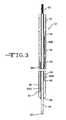
- FIG. 3shows the proximal end of the stylet uncoupled from stimulation lead of FIG. 2 by removing the cap.
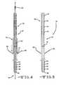
- FIG. 4shows how a tube being pushed over the lead to extend fin-type fixation elements attached at the lead intermediate section.
- FIG. 5shows the stimulation lead in a deployed state after separately removing the stylet and the tube used for activating the fixation elements on the lead body.
- FIG. 6shows a cross-section view of a stimulation lead assembly inserted through tissue and into a foramen, led by the pointed-tip stylet at the distal end.
- FIG. 7shows the stylet retracted from the distal end of FIG. 6 and placement of the stimulation lead at the stimulation site.
- FIG. 8shows a cross-section view of a tube being pushed over the implant lead to activate the fixation element on the intermediate portion of the lead.
- FIG. 9is a cross-sectional view showing deployment of the fixation element in tissue by the tube.
- FIG. 10shows a stimulation lead design with multiple fixation elements attached at different locations along the lead intermediate section.
- FIG. 11shows a cross-section view taken along line 11 - 11 of FIG. 10 .
- FIG. 12shows an activation tube used to deploy the fixation elements shown in FIG. 10 .
- FIG. 13shows a cross-sectional view along line 13 - 13 of FIG. 12 .
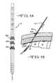
- FIG. 14shows tapered coils as fixation elements along a stimulation lead.
- FIG. 16shows a stimulation lead assembly having an elongated pointed-tip lead carrier.
- FIG. 17shows a cross-sectional view of the lead assembly with the pointed-tip lead carrier disengaged from the lead.
- FIG. 18is a cross-sectional view taken along line 18 - 18 of FIG. 16 .
- FIG. 19shows a cross-sectional view of the disengagement of lead carrier from lead via rotation.
- FIG. 20shows a complete disengagement of the lead carrier from the lead after being rotated out of the way.
- FIG. 22is a flowchart of a first minimally invasive method embodiment.
- FIG. 1shows an embodiment of an implanted neurostimulator 26 for stimulating sacral nerves 27 located near the sacrum 28 .
- the sacral nervesare accessible through an entry point in the skin along an insertion path 33 into a foramen 31 to reach a desired location 35 .
- a neurostimula ion systemcan include a stimulation lead 30 , an optional lead extension 32 , an implantable neurostimulator 26 , a physician programmer (not shown), and a patient programmer (not shown).
- the stimulation lead 30has electrical contacts 34 positioned on the distal end to stimulate nerves, and connectors (not shown) on the proximal end to connect to a lead extension or directly to the implantable neurostimulator 26 .
- the implantable neurostimulator 26provides a programmable stimulation signal that is delivered to a desired location to stimulate selected nerves.
- the implantable neurostimulator 26is typically implanted in a subcutaneous pocket around the upper buttocks, sometime after the stimulation lead 30 has been implanted and its effectiveness verified.
- the physician programmeris used by the clinician to program the stimulation signal produced by the implantable neurostimulator 26 .
- the patient programmerallows the patient to communicate with the implantable neurostimulator to control certain parameters of the stimulation signal typically selected by a clinician. For example, with a pelvic floor disorder, a patient can typically control stimulation signal parameters such as voltage amplitude.
- FIG. 2shows a lead assembly 36 comprising a stimulation lead 37 and a pointed tip stylet 60 .
- the stimulation lead 37has a proximal portion 38 , a distal portion 40 and an intermediate portion 39 .
- the distal portionhas four electrical contacts 44 , 46 , 48 and 50 serving as stimulation electrodes. These contacts can be made of iridium/platinum alloy rings.
- the lead proximal portionalso has four electrical connectors 52 , 54 , 56 and 58 for connecting the lead proximal portion 38 to the neurostimulator 26 . These electric connectors can be made of stainless steel rings.
- Electric pulses from the neurostimulator 26run through the proximal connectors 52 , 54 , 56 and 58 and along the lead body to the distal electrodes 44 , 46 , 48 and 50 via respective electrical wires 61 A, 61 B, 61 C and 61 D ( FIG. 2A ).
- the distal electrode 44is connected by wire 61 D to the proximal connector 52
- electrode 48is connected by wire 61 B to the proximal connector 56 .
- These wiresare embedded in the lead insulation body 70 ( FIG. 2A ).
- the connection of a wire at its ends to a distal electrode and a proximal connectorcan be achieved by various means, for example, laser welding. This is shown in FIG. 2A where a laser welded connection 68 links wire 61 A to electrode 50 .
- the insulation portion of the lead bodyis made of biocompatible silicone or polyurethane.
- the proximal connectors 52 , 54 , 56 and 58 and distal electrodes 44 , 46 , 48 and 50can be partially embedded in the lead body to form a diametric profile and to minimize trauma during lead implant. This partial embedding can be achieved by grinding or thermal reflow.
- the lead bodyhas a central lumen 41 extending from the proximal portion 38 to the distal end 40 .
- the stylet 60runs through the central lumen thereof.
- the stylet 60has a distal end 64 with a pointed tip 65 . In use, the distal end 64 extends out of the lead body a sufficient distance to expose the pointed tip 65 .
- the stylet 60also has a coupling element 62 at its proximal portion 63 that couples with the lead proximal portion 38 .
- this coupling element 62can be a removable cap attached at the stylet proximal end 63 .
- this coupling elementcan also be removably attached to the stylet proximal end 63 and lead proximal portion 38 , for example a clamp holding the lead and the stylet together.
- the coupling element 62helps prevent stylet movement inside the lumen 41 . That is so the lead assembly 36 can be inserted as a single unit by holding both its intermediate portion 39 and optionally its proximal portion 38 .
- the coupling element 62is removed and the stylet 60 moved back and forth within the central lumen 41 by pulling or pushing its proximal end against the lead proximal portion 38 .
- the stylet 60can be made of metal that is electrically conductive. That is so electric pulses can be fed from its proximal end into its distal end 64 where the pulses will evoke a patient motor or sensory response.
- the stylet distal endcan be partially insulated, for example by a thin layer of polytetrafluoroethylene (PTFE), with only the tip 65 being left exposed.
- PTFEpolytetrafluoroethylene
- FIG. 25shows a tapered end 42 at the lead distal portion 40 .
- the final location of the leadcan be verified by feeding electric pulses from at least one of the lead proximal connectors 52 to 58 to at least one of the distal electrodes 44 to 50 .
- a fixation elementis of a fin-like structure 66 .
- the fins 66are finger-like structures having an length substantially longer than their diameter or width taken along a cross-section perpendicular to the length thereof. They are preferably of an elastic material, for example, of polyurethane or silicone and only one of their ends is attached on the outer surface of the lead intermediate portion 39 . Attachment can be achieved by injection molding or adhesive bonding. Before the fixation fins 66 are deployed into tissue, the opposite ends of the fins should be pointed toward the lead proximal portion 38 . That is in order to reduce resistance when entering tissue during the lead insertion process.
- a preferred embodiment of the current inventionincludes a tube 72 ( FIG. 4 ).
- the tube 72is positioned over the lead body and pushed down from the proximal portion 38 toward the lead intermediate portion 39 until the distal tube end 74 touches the fixation fins 66 .
- Tube 72first touches the non-attached ends of the fins 66 and pushes them away from the lead intermediate portion 39 . This movement stops when the tube 72 contacts the attached ends of the fins 66 .
- the fixation elementis moved from its initial state ( FIG. 2 ) into its final deployed state ( FIG. 4 ) via tube 72 .
- FIG. 5shows the lead with the fixation fins 66 deployed and the tube 72 removed from the lead 37 .
- FIGS. 6 to 9show a minimally invasive method for implanting the above-described stimulation lead-stylet assembly 36 percutaneously. The method is also described in the flowchart of FIG. 22 .
- a local anestheticis typically applied to the area where the stimulation lead-stylet assembly 36 will be implanted, for example, posterior to the sacrum 28 .
- an implanting cliniciancan include the patient's conscious sensory responses to electric stimuli to aid in placing the stimulation lead-stylet assembly 36 .
- the lead-stylet assembly 36is hand guided 98 into the foramen 31 along an insertion path 33 .
- the foramen's 31 approximate locationcan be found using anatomical landmarks, fluoroscopy or x-ray images.
- the coupling 62 between the stimulation lead and styletis removed.
- the desired stimulation sitecan be first probed by the stylet and sensed by a variety of means such as by applying electric pulses to the stylet 60 at its proximal end 63 to evoke a patient response, such as a motor or sensory response.
- the tapered stimulation leadcan be pushed over the stylet and moved into the identified stimulation site.
- FIG. 10A preferred embodiment comprising multiple fixation fins supported on a stimulation lead 37 is shown in FIG. 10 .
- this embodimenthas three fin-like fixation elements 66 A, 66 B and 660 , each having only one end attached to the lead body. The opposite end of the fins extends away from the lead surface when it is deployed by tube 72 in a similar manner as shown in FIG. 4 .
- These fixation elementscan be made of material having elastic properties, such as polyurethane or silicone, and are similar to the fins 66 described in FIGS. 2 , 4 and 5 . However, they are attached to the lead intermediate portion 39 at different axial locations. Initially, the non-attached ends point to the lead proximal portion 38 during insertion of the lead-stylet assembly 36 .
- the three fixation elementsare preferably about 120 degrees from each other.
- the deployment tube 72 shown in FIG. 12has three slots 76 , 78 and 80 with different lengths measured from the tube 72 distal end at the tube distal portion 74 . As shown in FIG. 13 , these slots are also about 120 degrees apart from each other. That is so when the tube 72 is pushed over the lead-stylet assembly 36 , the length and orientation of the various slots deploys only one of the fixation fins 66 A to 660 . For example, slot 76 only deploys fixation element 66 A, slot 78 only deploys a respective fixation element 66 B, and slot 80 only deploys fixation element 660 .
- FIG. 14shows another preferred embodiment of a fixation structure.
- there are three tapered coils 82 A, 82 B and 820each having a smaller diameter end and a larger diameter end. Only the smaller diameter end is attached to the surface of the lead intermediate portion 39 with the remainder of the coil surrounding the perimeter of the lead.
- the tapered coilscan be twisted in one direction at their larger end. This causes their larger diameters to shrink so that the coil fits into a tube 73 whose inner diameter is smaller than the coil's uncoiled diameter.
- the lead-stylet assemblyin this case will also include the tube 73 covering only the lead intermediate portion 39 and part of lead distal portion 38 (not shown).
- the entire lead assembly including the tube 73is inserted into body tissue.
- the tube 73is retracted from the stimulation lead.
- the coilsare released from inside the tube 73 and expand like a torsion spring surrounding the lead.
- At least one of the tapered coilsis preferably expanded within the lumbosacral fascial layer.
- These tapered coilsare preferably made of biocompatible metals, such as stainless steel, platinum, titanium, NP35N, or nitinol.
- the larger ends of the coilsare shown facing distally, that is not necessary. In an alternative embodiment, the larger coil ends can face proximally. Still further, one of the coils could have its larger end facing distally while another has its larger end facing proximally.
- the point-tip stylet 60is removed 102 via the lead central lumen 41 .
- re-verification of lead position at the desired stimulation siteshould be repeated as described previously.
- a skin incisionis made for implanting the neurostimulator, i.e., the implantable pulse generator (IPG).
- IPGimplantable pulse generator
- the lead proximal portion 38is tunneled under the skin to bring it adjacent to the implanted IPG and then to the lead proximal connectors 52 , 54 , 56 and 58 are connected 106 to the appropriate IPG receptacles (not shown). After the IPG is activated, patient feedback is acquired to make sure the desired neural stimulation is achieved. Finally, the skin incisions for both the lead entry point and the IPG implant site are closed 108 .
- FIG. 23shows a variation 94 of the preferred embodiment in FIG. 22 of the current invention.
- a needle similar to the stylet 60 and having a diameter much smaller than the assembly 36is inserted first 110 to probe the desired stimulation site 112 .
- the implant clinicianrecords the needle depth and orientation as a reference, and the needle is removed.
- the recorded needle depth and orientation informationis then used to guide insertion 96 of lead-stylet assembly 36 .
- the remainder of the procedure stepsare the same as in flowchart 92 .
- comparing the flowcharts 92 and 94it is seen that the latter enables an implant clinician to probe several sites with relatively more ease before implanting the lead assembly 36 than in the former. This helps reduce trauma to the patient and enhance therapy effectiveness.
- FIGS. 16 and 17Another variation of the preferred embodiment of the lead stylet assembly 36 is the implant assembly shown in FIGS. 16 and 17 having an elongated carrier body 84 , a lead body 37 and a stylet 88 .
- the lead body 37has a central lumen 41 , which does not run through to the lead tip. This means that the distal end of the stylet 88 within the lead body 37 is not exposed out from the distal end of the lead tip 40 .
- the carrier body 84has a pointed tip 86 for cutting through tissue during implantation.
- the side wall of the carrier body 84is sized to accommodate the lead body 37 . With the lead body 37 nested in the carrier body, the lead tip 40 resides in a longitudinal cavity 90 extending along the distal end of the carrier.
- the distal end of the carrier 84is then inserted into tissue in a similar manner as previously described with respect to the assembly 36 .
- the clinicianholds the lead body 37 and stylet 88 in place and pushes the carrier body 84 further forward, as shown by the arrow in FIG. 17 . This caused the lead distal end 40 to separate from the carrier body cavity 90 .
- the carrier body 84is rotated out of the way relative to the lead body 37 ( FIG. 19 ). This ensures that the cavity 90 does not re-engage with the lead tip 40 during removal ( FIG. 20 ).
- the leadis implanted into body tissue using either the previously described fixation fins 66 or the tapered coils.
- the stylet 88is then removed, from the lead central lumen with only the stimulation lead 35 being left in place ( FIG. 21 ).
- embodiments of minimally invasive sacral lead implantation methods 92 and 94are disclosed with many benefits. Embodiments of the methods can simplify the implant procedure, reduce trauma to the patient during implant procedure, reduce patient recovery time, and reduce healthcare costs.
- One skilled in the artwill appreciate that the present invention can be practiced with embodiments other than those disclosed. The disclosed embodiments are presented for purposes of illustration and not limitation, and the present invention is limited only by the claims that follow.
Landscapes
- Health & Medical Sciences (AREA)
- Neurology (AREA)
- Animal Behavior & Ethology (AREA)
- General Health & Medical Sciences (AREA)
- Biomedical Technology (AREA)
- Nuclear Medicine, Radiotherapy & Molecular Imaging (AREA)
- Radiology & Medical Imaging (AREA)
- Life Sciences & Earth Sciences (AREA)
- Veterinary Medicine (AREA)
- Engineering & Computer Science (AREA)
- Public Health (AREA)
- Neurosurgery (AREA)
- Orthopedic Medicine & Surgery (AREA)
- Cardiology (AREA)
- Heart & Thoracic Surgery (AREA)
- Electrotherapy Devices (AREA)
Abstract
Description
Claims (12)
Priority Applications (3)
| Application Number | Priority Date | Filing Date | Title |
|---|---|---|---|
| US12/506,282US8634932B1 (en) | 2008-07-21 | 2009-07-21 | Minimally invasive methods for implanting a sacral stimulation lead |
| US14/033,592US8781603B2 (en) | 2008-07-21 | 2013-09-23 | Minimally invasive methods for implanting a sacral stimulation lead |
| US14/327,962US20140324144A1 (en) | 2008-07-21 | 2014-07-10 | Minimally invasive methods for implanting a sacral stimulation lead |
Applications Claiming Priority (2)
| Application Number | Priority Date | Filing Date | Title |
|---|---|---|---|
| US8227108P | 2008-07-21 | 2008-07-21 | |
| US12/506,282US8634932B1 (en) | 2008-07-21 | 2009-07-21 | Minimally invasive methods for implanting a sacral stimulation lead |
Related Child Applications (1)
| Application Number | Title | Priority Date | Filing Date |
|---|---|---|---|
| US14/033,592DivisionUS8781603B2 (en) | 2008-07-21 | 2013-09-23 | Minimally invasive methods for implanting a sacral stimulation lead |
Publications (1)
| Publication Number | Publication Date |
|---|---|
| US8634932B1true US8634932B1 (en) | 2014-01-21 |
Family
ID=49919293
Family Applications (3)
| Application Number | Title | Priority Date | Filing Date |
|---|---|---|---|
| US12/506,282Active2032-11-20US8634932B1 (en) | 2008-07-21 | 2009-07-21 | Minimally invasive methods for implanting a sacral stimulation lead |
| US14/033,592ActiveUS8781603B2 (en) | 2008-07-21 | 2013-09-23 | Minimally invasive methods for implanting a sacral stimulation lead |
| US14/327,962AbandonedUS20140324144A1 (en) | 2008-07-21 | 2014-07-10 | Minimally invasive methods for implanting a sacral stimulation lead |
Family Applications After (2)
| Application Number | Title | Priority Date | Filing Date |
|---|---|---|---|
| US14/033,592ActiveUS8781603B2 (en) | 2008-07-21 | 2013-09-23 | Minimally invasive methods for implanting a sacral stimulation lead |
| US14/327,962AbandonedUS20140324144A1 (en) | 2008-07-21 | 2014-07-10 | Minimally invasive methods for implanting a sacral stimulation lead |
Country Status (1)
| Country | Link |
|---|---|
| US (3) | US8634932B1 (en) |
Cited By (15)
| Publication number | Priority date | Publication date | Assignee | Title |
|---|---|---|---|---|
| US20150134041A1 (en)* | 2013-11-08 | 2015-05-14 | Greatbatch Ltd. | Implantable medical lead for stimulation of multiple nerves |
| WO2016126340A3 (en)* | 2014-12-23 | 2016-10-27 | The Regents Of The University Of California | Methods, compositions, and systems for device implantation |
| US9533155B2 (en) | 2014-08-15 | 2017-01-03 | Axonics Modulation Technologies, Inc. | Methods for determining neurostimulation electrode configurations based on neural localization |
| US9555246B2 (en) | 2014-08-15 | 2017-01-31 | Axonics Modulation Technologies, Inc. | Electromyographic lead positioning and stimulation titration in a nerve stimulation system for treatment of overactive bladder |
| US10016600B2 (en) | 2013-05-30 | 2018-07-10 | Neurostim Solutions, Llc | Topical neurological stimulation |
| US10092762B2 (en) | 2014-08-15 | 2018-10-09 | Axonics Modulation Technologies, Inc. | Integrated electromyographic clinician programmer for use with an implantable neurostimulator |
| US10953225B2 (en) | 2017-11-07 | 2021-03-23 | Neurostim Oab, Inc. | Non-invasive nerve activator with adaptive circuit |
| US11077301B2 (en) | 2015-02-21 | 2021-08-03 | NeurostimOAB, Inc. | Topical nerve stimulator and sensor for bladder control |
| US11229789B2 (en) | 2013-05-30 | 2022-01-25 | Neurostim Oab, Inc. | Neuro activator with controller |
| WO2022026242A1 (en)* | 2020-07-27 | 2022-02-03 | Medtronic, Inc. | Implantable medical lead |
| US20220280790A1 (en)* | 2012-04-26 | 2022-09-08 | Medtronic, Inc. | Trial stimulation systems |
| US11439829B2 (en) | 2019-05-24 | 2022-09-13 | Axonics, Inc. | Clinician programmer methods and systems for maintaining target operating temperatures |
| US11458311B2 (en) | 2019-06-26 | 2022-10-04 | Neurostim Technologies Llc | Non-invasive nerve activator patch with adaptive circuit |
| US11730958B2 (en) | 2019-12-16 | 2023-08-22 | Neurostim Solutions, Llc | Non-invasive nerve activator with boosted charge delivery |
| US11848090B2 (en) | 2019-05-24 | 2023-12-19 | Axonics, Inc. | Trainer for a neurostimulator programmer and associated methods of use with a neurostimulation system |
Families Citing this family (12)
| Publication number | Priority date | Publication date | Assignee | Title |
|---|---|---|---|---|
| US20100256696A1 (en)* | 2009-04-07 | 2010-10-07 | Boston Scientific Neuromodulation Corporation | Anchoring Units For Implantable Electrical Stimulation Systems And Methods Of Making And Using |
| US9603526B2 (en) | 2013-11-01 | 2017-03-28 | CMAP Technology, LLC | Systems and methods for compound motor action potential monitoring with neuromodulation of the pelvis and other body regions |
| US11633593B2 (en) | 2013-11-27 | 2023-04-25 | Ebt Medical, Inc. | Treatment of pelvic floor disorders using targeted lower limb nerve stimulation |
| US10556107B2 (en) | 2013-11-27 | 2020-02-11 | Ebt Medical, Inc. | Systems, methods and kits for peripheral nerve stimulation |
| US9610442B2 (en) | 2015-05-21 | 2017-04-04 | The Governing Council Of The University Of Toronto | Systems and methods for treatment of urinary dysfunction |
| US20160263376A1 (en) | 2013-11-27 | 2016-09-15 | The Governing Council Of The University Of Toronto | Systems and methods for improved treatment of overactive bladder |
| US9339263B2 (en)* | 2014-01-03 | 2016-05-17 | DePuy Synthes Products, Inc. | Dilation system and method |
| AU2017371223B2 (en) | 2016-12-09 | 2023-04-27 | Zenflow, Inc. | Systems, devices, and methods for the accurate deployment of an implant in the prostatic urethra |
| US10709886B2 (en) | 2017-02-28 | 2020-07-14 | Boston Scientific Neuromodulation Corporation | Electrical stimulation leads and systems with elongate anchoring elements and methods of making and using |
| US10835739B2 (en) | 2017-03-24 | 2020-11-17 | Boston Scientific Neuromodulation Corporation | Electrical stimulation leads and systems with elongate anchoring elements and methods of making and using |
| WO2019165108A1 (en)* | 2018-02-22 | 2019-08-29 | Axonics Modulation Technologies, Inc. | Neurostimulation leads for trial nerve stimulation and methods of use |
| US11890213B2 (en) | 2019-11-19 | 2024-02-06 | Zenflow, Inc. | Systems, devices, and methods for the accurate deployment and imaging of an implant in the prostatic urethra |
Citations (6)
| Publication number | Priority date | Publication date | Assignee | Title |
|---|---|---|---|---|
| US4913164A (en)* | 1988-09-27 | 1990-04-03 | Intermedics, Inc. | Extensible passive fixation mechanism for lead assembly of an implantable cardiac stimulator |
| US5390671A (en) | 1994-03-15 | 1995-02-21 | Minimed Inc. | Transcutaneous sensor insertion set |
| US6971393B1 (en) | 2000-11-15 | 2005-12-06 | George Mamo | Minimally invasive method for implanting a sacral stimulation lead |
| US6999819B2 (en) | 2001-08-31 | 2006-02-14 | Medtronic, Inc. | Implantable medical electrical stimulation lead fixation method and apparatus |
| US7328068B2 (en) | 2003-03-31 | 2008-02-05 | Medtronic, Inc. | Method, system and device for treating disorders of the pelvic floor by means of electrical stimulation of the pudendal and associated nerves, and the optional delivery of drugs in association therewith |
| US7328069B2 (en) | 2002-09-06 | 2008-02-05 | Medtronic, Inc. | Method, system and device for treating disorders of the pelvic floor by electrical stimulation of and the delivery of drugs to the left and right pudendal nerves |
Family Cites Families (5)
| Publication number | Priority date | Publication date | Assignee | Title |
|---|---|---|---|---|
| US4585013A (en)* | 1981-04-20 | 1986-04-29 | Cordis Corporation | Lumenless pervenous electrical lead and method of implantation |
| US5380290A (en)* | 1992-04-16 | 1995-01-10 | Pfizer Hospital Products Group, Inc. | Body access device |
| US6909920B2 (en)* | 2001-04-27 | 2005-06-21 | Medtronic, Inc. | System and method for positioning an implantable medical device within a body |
| US7532939B2 (en)* | 2005-07-21 | 2009-05-12 | Medtronic, Inc. | Active fixation medical lead |
| JP5562648B2 (en)* | 2007-01-29 | 2014-07-30 | スパイナル・モデュレーション・インコーポレイテッド | Non-stitched top retaining mechanism |
- 2009
- 2009-07-21USUS12/506,282patent/US8634932B1/enactiveActive
- 2013
- 2013-09-23USUS14/033,592patent/US8781603B2/enactiveActive
- 2014
- 2014-07-10USUS14/327,962patent/US20140324144A1/ennot_activeAbandoned
Patent Citations (7)
| Publication number | Priority date | Publication date | Assignee | Title |
|---|---|---|---|---|
| US4913164A (en)* | 1988-09-27 | 1990-04-03 | Intermedics, Inc. | Extensible passive fixation mechanism for lead assembly of an implantable cardiac stimulator |
| US5390671A (en) | 1994-03-15 | 1995-02-21 | Minimed Inc. | Transcutaneous sensor insertion set |
| US6971393B1 (en) | 2000-11-15 | 2005-12-06 | George Mamo | Minimally invasive method for implanting a sacral stimulation lead |
| US6999819B2 (en) | 2001-08-31 | 2006-02-14 | Medtronic, Inc. | Implantable medical electrical stimulation lead fixation method and apparatus |
| US7330764B2 (en) | 2001-08-31 | 2008-02-12 | Medtronic, Inc. | Implantable medical electrical stimulation lead fixation method and apparatus |
| US7328069B2 (en) | 2002-09-06 | 2008-02-05 | Medtronic, Inc. | Method, system and device for treating disorders of the pelvic floor by electrical stimulation of and the delivery of drugs to the left and right pudendal nerves |
| US7328068B2 (en) | 2003-03-31 | 2008-02-05 | Medtronic, Inc. | Method, system and device for treating disorders of the pelvic floor by means of electrical stimulation of the pudendal and associated nerves, and the optional delivery of drugs in association therewith |
Cited By (34)
| Publication number | Priority date | Publication date | Assignee | Title |
|---|---|---|---|---|
| US11806527B2 (en) | 2012-04-26 | 2023-11-07 | Medtronic, Inc. | Trial stimulation systems |
| US11517752B2 (en)* | 2012-04-26 | 2022-12-06 | Medtronic, Inc. | Trial stimulation systems |
| US20220280790A1 (en)* | 2012-04-26 | 2022-09-08 | Medtronic, Inc. | Trial stimulation systems |
| US10016600B2 (en) | 2013-05-30 | 2018-07-10 | Neurostim Solutions, Llc | Topical neurological stimulation |
| US11291828B2 (en) | 2013-05-30 | 2022-04-05 | Neurostim Solutions LLC | Topical neurological stimulation |
| US11229789B2 (en) | 2013-05-30 | 2022-01-25 | Neurostim Oab, Inc. | Neuro activator with controller |
| US10918853B2 (en) | 2013-05-30 | 2021-02-16 | Neurostim Solutions, Llc | Topical neurological stimulation |
| US10307591B2 (en) | 2013-05-30 | 2019-06-04 | Neurostim Solutions, Llc | Topical neurological stimulation |
| US10946185B2 (en) | 2013-05-30 | 2021-03-16 | Neurostim Solutions, Llc | Topical neurological stimulation |
| US9511230B2 (en)* | 2013-11-08 | 2016-12-06 | Nuvectra Corporation | Implantable medical lead for stimulation of multiple nerves |
| US20170080217A1 (en)* | 2013-11-08 | 2017-03-23 | Nuvectra Corporation | Implantable medical lead for stimulation of multiple nerves |
| US9889293B2 (en)* | 2013-11-08 | 2018-02-13 | Nuvectra Corporation | Implantable medical lead for stimulation of multiple nerves |
| US20150134041A1 (en)* | 2013-11-08 | 2015-05-14 | Greatbatch Ltd. | Implantable medical lead for stimulation of multiple nerves |
| US10406369B2 (en) | 2014-08-15 | 2019-09-10 | Axonics Modulation Technologies, Inc. | Electromyographic lead positioning and stimulation titration in a nerve stimulation system for treatment of overactive bladder |
| US9533155B2 (en) | 2014-08-15 | 2017-01-03 | Axonics Modulation Technologies, Inc. | Methods for determining neurostimulation electrode configurations based on neural localization |
| US11497916B2 (en) | 2014-08-15 | 2022-11-15 | Axonics, Inc. | Electromyographic lead positioning and stimulation titration in a nerve stimulation system for treatment of overactive bladder |
| US10092762B2 (en) | 2014-08-15 | 2018-10-09 | Axonics Modulation Technologies, Inc. | Integrated electromyographic clinician programmer for use with an implantable neurostimulator |
| US11730411B2 (en) | 2014-08-15 | 2023-08-22 | Axonics, Inc. | Methods for determining neurostimulation electrode configurations based on neural localization |
| US11116985B2 (en) | 2014-08-15 | 2021-09-14 | Axonics, Inc. | Clinician programmer for use with an implantable neurostimulation lead |
| US9855423B2 (en) | 2014-08-15 | 2018-01-02 | Axonics Modulation Technologies, Inc. | Systems and methods for neurostimulation electrode configurations based on neural localization |
| US10729903B2 (en) | 2014-08-15 | 2020-08-04 | Axonics Modulation Technologies, Inc. | Methods for determining neurostimulation electrode configurations based on neural localization |
| US9561372B2 (en) | 2014-08-15 | 2017-02-07 | Axonics Modulation Technologies, Inc. | Electromyographic lead positioning and stimulation titration in a nerve stimulation system for treatment of overactive bladder |
| US9555246B2 (en) | 2014-08-15 | 2017-01-31 | Axonics Modulation Technologies, Inc. | Electromyographic lead positioning and stimulation titration in a nerve stimulation system for treatment of overactive bladder |
| US11963697B2 (en) | 2014-12-23 | 2024-04-23 | The Regents Of The University Of California | Methods, compositions, and systems for device implantation |
| US11660115B2 (en) | 2014-12-23 | 2023-05-30 | The Regents Of The University Of California | Methods, compositions, and systems for device implantation |
| WO2016126340A3 (en)* | 2014-12-23 | 2016-10-27 | The Regents Of The University Of California | Methods, compositions, and systems for device implantation |
| US11077301B2 (en) | 2015-02-21 | 2021-08-03 | NeurostimOAB, Inc. | Topical nerve stimulator and sensor for bladder control |
| US10953225B2 (en) | 2017-11-07 | 2021-03-23 | Neurostim Oab, Inc. | Non-invasive nerve activator with adaptive circuit |
| US11439829B2 (en) | 2019-05-24 | 2022-09-13 | Axonics, Inc. | Clinician programmer methods and systems for maintaining target operating temperatures |
| US11848090B2 (en) | 2019-05-24 | 2023-12-19 | Axonics, Inc. | Trainer for a neurostimulator programmer and associated methods of use with a neurostimulation system |
| US11458311B2 (en) | 2019-06-26 | 2022-10-04 | Neurostim Technologies Llc | Non-invasive nerve activator patch with adaptive circuit |
| US11730958B2 (en) | 2019-12-16 | 2023-08-22 | Neurostim Solutions, Llc | Non-invasive nerve activator with boosted charge delivery |
| WO2022026242A1 (en)* | 2020-07-27 | 2022-02-03 | Medtronic, Inc. | Implantable medical lead |
| US12194293B2 (en) | 2020-07-27 | 2025-01-14 | Medtronic, Inc. | Implantable medical lead |
Also Published As
| Publication number | Publication date |
|---|---|
| US20140324144A1 (en) | 2014-10-30 |
| US20140031909A1 (en) | 2014-01-30 |
| US8781603B2 (en) | 2014-07-15 |
Similar Documents
| Publication | Publication Date | Title |
|---|---|---|
| US8634932B1 (en) | Minimally invasive methods for implanting a sacral stimulation lead | |
| US9907476B2 (en) | Multi-electrode peripheral nerve evaluation lead and related system and method of use | |
| US8204569B2 (en) | Implantable medical electrical stimulation lead fixation method and apparatus | |
| US8457763B2 (en) | Implantable medical electrical stimulation lead fixation method and apparatus | |
| JP7677791B2 (en) | Neurostimulation leads for experimental neurostimulation and methods of use - Patents.com | |
| US6512958B1 (en) | Percutaneous medical probe and flexible guide wire | |
| US7881783B2 (en) | Implantable medical electrical stimulation lead, such as a PNE lead, and method of use | |
| JP7476188B2 (en) | Devices, systems and methods for the treatment of neurogenic bladder | |
| US8200343B2 (en) | Implantable medical electrical stimulation lead fixation method and apparatus | |
| US7763034B2 (en) | Transobturator lead implantation for pelvic floor stimulation | |
| US9427573B2 (en) | Deployable electrode lead anchor | |
| US20210361952A1 (en) | Implantable electrical stimulator with deflecting tip lead | |
| US8145323B2 (en) | Implantable medical electrical stimulation lead fixation method and apparatus | |
| US20070255367A1 (en) | Implantable Medical Electrical Stimulation Lead Fixation Method and Apparatus | |
| WO2004012809A1 (en) | A method and system for inserting an electrode | |
| US20110202097A1 (en) | System and method for electrically probing and providing medical electrical stimulation |
Legal Events
| Date | Code | Title | Description |
|---|---|---|---|
| AS | Assignment | Owner name:GREATBATCH LTD., NEW YORK Free format text:ASSIGNMENT OF ASSIGNORS INTEREST;ASSIGNORS:YE, QINGSHAN;SWOYER, JOHN M.;SIGNING DATES FROM 20090708 TO 20090720;REEL/FRAME:022979/0307 | |
| STCF | Information on status: patent grant | Free format text:PATENTED CASE | |
| CC | Certificate of correction | ||
| AS | Assignment | Owner name:MANUFACTURERS AND TRADERS TRUST COMPANY, NEW YORK Free format text:SECURITY INTEREST;ASSIGNORS:GREATBATCH, INC.;GREATBATCH LTD.;ELECTROCHEM SOLUTIONS, INC.;AND OTHERS;REEL/FRAME:036980/0482 Effective date:20151027 | |
| AS | Assignment | Owner name:QIG GROUP, LLC, NEW YORK Free format text:ASSIGNMENT OF ASSIGNORS INTEREST;ASSIGNOR:GREATBATCH LTD.;REEL/FRAME:037810/0051 Effective date:20160212 | |
| AS | Assignment | Owner name:MICRO POWER ELECTRONICS, INC., OREGON Free format text:RELEASE BY SECURED PARTY;ASSIGNOR:MANUFACTURERS AND TRADERS TRUST COMPANY;REEL/FRAME:039132/0773 Effective date:20160418 Owner name:GREATBATCH INC., NEW YORK Free format text:RELEASE BY SECURED PARTY;ASSIGNOR:MANUFACTURERS AND TRADERS TRUST COMPANY;REEL/FRAME:039132/0773 Effective date:20160418 Owner name:ELECTROCHEM SOLUTIONS, INC., NEW YORK Free format text:RELEASE BY SECURED PARTY;ASSIGNOR:MANUFACTURERS AND TRADERS TRUST COMPANY;REEL/FRAME:039132/0773 Effective date:20160418 Owner name:QIG GROUP LLC, TEXAS Free format text:RELEASE BY SECURED PARTY;ASSIGNOR:MANUFACTURERS AND TRADERS TRUST COMPANY;REEL/FRAME:039132/0773 Effective date:20160418 Owner name:GREATBATCH LTD., NEW YORK Free format text:RELEASE BY SECURED PARTY;ASSIGNOR:MANUFACTURERS AND TRADERS TRUST COMPANY;REEL/FRAME:039132/0773 Effective date:20160418 Owner name:NEURONEXUS TECHNOLOGIES, INC., MICHIGAN Free format text:RELEASE BY SECURED PARTY;ASSIGNOR:MANUFACTURERS AND TRADERS TRUST COMPANY;REEL/FRAME:039132/0773 Effective date:20160418 | |
| AS | Assignment | Owner name:NUVECTRA CORPORATION, TEXAS Free format text:CHANGE OF NAME;ASSIGNOR:QIG GROUP LLC;REEL/FRAME:042310/0112 Effective date:20160212 | |
| FPAY | Fee payment | Year of fee payment:4 | |
| AS | Assignment | Owner name:CIRTEC MEDICAL CORP., MINNESOTA Free format text:ASSIGNMENT OF ASSIGNORS INTEREST;ASSIGNOR:NUVECTRA CORPORATION;REEL/FRAME:052185/0680 Effective date:20200317 | |
| MAFP | Maintenance fee payment | Free format text:PAYMENT OF MAINTENANCE FEE, 8TH YEAR, LARGE ENTITY (ORIGINAL EVENT CODE: M1552); ENTITY STATUS OF PATENT OWNER: LARGE ENTITY Year of fee payment:8 | |
| AS | Assignment | Owner name:MICRO POWER ELECTRONICS, INC., NEW YORK Free format text:RELEASE BY SECURED PARTY;ASSIGNOR:MANUFACTURERS AND TRADERS TRUST COMPANY (AS ADMINISTRATIVE AGENT);REEL/FRAME:060938/0069 Effective date:20210903 Owner name:PRECIMED INC., NEW YORK Free format text:RELEASE BY SECURED PARTY;ASSIGNOR:MANUFACTURERS AND TRADERS TRUST COMPANY (AS ADMINISTRATIVE AGENT);REEL/FRAME:060938/0069 Effective date:20210903 Owner name:GREATBATCH-GLOBE TOOL, INC., NEW YORK Free format text:RELEASE BY SECURED PARTY;ASSIGNOR:MANUFACTURERS AND TRADERS TRUST COMPANY (AS ADMINISTRATIVE AGENT);REEL/FRAME:060938/0069 Effective date:20210903 Owner name:NEURONEXUS TECHNOLOGIES, INC., NEW YORK Free format text:RELEASE BY SECURED PARTY;ASSIGNOR:MANUFACTURERS AND TRADERS TRUST COMPANY (AS ADMINISTRATIVE AGENT);REEL/FRAME:060938/0069 Effective date:20210903 Owner name:ELECTROCHEM SOLUTIONS, INC., NEW YORK Free format text:RELEASE BY SECURED PARTY;ASSIGNOR:MANUFACTURERS AND TRADERS TRUST COMPANY (AS ADMINISTRATIVE AGENT);REEL/FRAME:060938/0069 Effective date:20210903 Owner name:GREATBATCH LTD., NEW YORK Free format text:RELEASE BY SECURED PARTY;ASSIGNOR:MANUFACTURERS AND TRADERS TRUST COMPANY (AS ADMINISTRATIVE AGENT);REEL/FRAME:060938/0069 Effective date:20210903 Owner name:GREATBATCH, INC., NEW YORK Free format text:RELEASE BY SECURED PARTY;ASSIGNOR:MANUFACTURERS AND TRADERS TRUST COMPANY (AS ADMINISTRATIVE AGENT);REEL/FRAME:060938/0069 Effective date:20210903 | |
| AS | Assignment | Owner name:MICRO POWER ELECTRONICS, INC., NEW YORK Free format text:RELEASE BY SECURED PARTY;ASSIGNOR:MANUFACTURERS AND TRADERS TRUST COMPANY (AS ADMINISTRATIVE AGENT);REEL/FRAME:061659/0858 Effective date:20210903 Owner name:PRECIMED INC., NEW YORK Free format text:RELEASE BY SECURED PARTY;ASSIGNOR:MANUFACTURERS AND TRADERS TRUST COMPANY (AS ADMINISTRATIVE AGENT);REEL/FRAME:061659/0858 Effective date:20210903 Owner name:GREATBATCH-GLOBE TOOL, INC., NEW YORK Free format text:RELEASE BY SECURED PARTY;ASSIGNOR:MANUFACTURERS AND TRADERS TRUST COMPANY (AS ADMINISTRATIVE AGENT);REEL/FRAME:061659/0858 Effective date:20210903 Owner name:NEURONEXUS TECHNOLOGIES, INC., NEW YORK Free format text:RELEASE BY SECURED PARTY;ASSIGNOR:MANUFACTURERS AND TRADERS TRUST COMPANY (AS ADMINISTRATIVE AGENT);REEL/FRAME:061659/0858 Effective date:20210903 Owner name:ELECTROCHEM SOLUTIONS, INC., NEW YORK Free format text:RELEASE BY SECURED PARTY;ASSIGNOR:MANUFACTURERS AND TRADERS TRUST COMPANY (AS ADMINISTRATIVE AGENT);REEL/FRAME:061659/0858 Effective date:20210903 Owner name:GREATBATCH LTD., NEW YORK Free format text:RELEASE BY SECURED PARTY;ASSIGNOR:MANUFACTURERS AND TRADERS TRUST COMPANY (AS ADMINISTRATIVE AGENT);REEL/FRAME:061659/0858 Effective date:20210903 Owner name:GREATBATCH, INC., NEW YORK Free format text:RELEASE BY SECURED PARTY;ASSIGNOR:MANUFACTURERS AND TRADERS TRUST COMPANY (AS ADMINISTRATIVE AGENT);REEL/FRAME:061659/0858 Effective date:20210903 | |
| AS | Assignment | Owner name:BMO HARRIS BANK N.A., AS COLLATERAL AGENT, ILLINOIS Free format text:PATENT SECURITY AGREEMENT;ASSIGNOR:CIRTEC MEDICAL CORP.;REEL/FRAME:062559/0098 Effective date:20230130 | |
| MAFP | Maintenance fee payment | Free format text:PAYMENT OF MAINTENANCE FEE, 12TH YEAR, LARGE ENTITY (ORIGINAL EVENT CODE: M1553); ENTITY STATUS OF PATENT OWNER: LARGE ENTITY Year of fee payment:12 |