US8632591B2 - Nucleus prostheses - Google Patents
Nucleus prosthesesDownload PDFInfo
- Publication number
- US8632591B2 US8632591B2US11/874,144US87414407AUS8632591B2US 8632591 B2US8632591 B2US 8632591B2US 87414407 AUS87414407 AUS 87414407AUS 8632591 B2US8632591 B2US 8632591B2
- Authority
- US
- United States
- Prior art keywords
- prosthesis
- segments
- segment
- ligament
- interlocking element
- Prior art date
- Legal status (The legal status is an assumption and is not a legal conclusion. Google has not performed a legal analysis and makes no representation as to the accuracy of the status listed.)
- Expired - Fee Related, expires
Links
Images


Classifications
- A—HUMAN NECESSITIES
- A61—MEDICAL OR VETERINARY SCIENCE; HYGIENE
- A61F—FILTERS IMPLANTABLE INTO BLOOD VESSELS; PROSTHESES; DEVICES PROVIDING PATENCY TO, OR PREVENTING COLLAPSING OF, TUBULAR STRUCTURES OF THE BODY, e.g. STENTS; ORTHOPAEDIC, NURSING OR CONTRACEPTIVE DEVICES; FOMENTATION; TREATMENT OR PROTECTION OF EYES OR EARS; BANDAGES, DRESSINGS OR ABSORBENT PADS; FIRST-AID KITS
- A61F2/00—Filters implantable into blood vessels; Prostheses, i.e. artificial substitutes or replacements for parts of the body; Appliances for connecting them with the body; Devices providing patency to, or preventing collapsing of, tubular structures of the body, e.g. stents
- A61F2/02—Prostheses implantable into the body
- A61F2/30—Joints
- A61F2/44—Joints for the spine, e.g. vertebrae, spinal discs
- A61F2/4455—Joints for the spine, e.g. vertebrae, spinal discs for the fusion of spinal bodies, e.g. intervertebral fusion of adjacent spinal bodies, e.g. fusion cages
- A61F2/4465—Joints for the spine, e.g. vertebrae, spinal discs for the fusion of spinal bodies, e.g. intervertebral fusion of adjacent spinal bodies, e.g. fusion cages having a circular or kidney shaped cross-section substantially perpendicular to the axis of the spine
- A—HUMAN NECESSITIES
- A61—MEDICAL OR VETERINARY SCIENCE; HYGIENE
- A61F—FILTERS IMPLANTABLE INTO BLOOD VESSELS; PROSTHESES; DEVICES PROVIDING PATENCY TO, OR PREVENTING COLLAPSING OF, TUBULAR STRUCTURES OF THE BODY, e.g. STENTS; ORTHOPAEDIC, NURSING OR CONTRACEPTIVE DEVICES; FOMENTATION; TREATMENT OR PROTECTION OF EYES OR EARS; BANDAGES, DRESSINGS OR ABSORBENT PADS; FIRST-AID KITS
- A61F2/00—Filters implantable into blood vessels; Prostheses, i.e. artificial substitutes or replacements for parts of the body; Appliances for connecting them with the body; Devices providing patency to, or preventing collapsing of, tubular structures of the body, e.g. stents
- A61F2/02—Prostheses implantable into the body
- A61F2/30—Joints
- A61F2/44—Joints for the spine, e.g. vertebrae, spinal discs
- A—HUMAN NECESSITIES
- A61—MEDICAL OR VETERINARY SCIENCE; HYGIENE
- A61B—DIAGNOSIS; SURGERY; IDENTIFICATION
- A61B17/00—Surgical instruments, devices or methods
- A61B17/56—Surgical instruments or methods for treatment of bones or joints; Devices specially adapted therefor
- A61B17/58—Surgical instruments or methods for treatment of bones or joints; Devices specially adapted therefor for osteosynthesis, e.g. bone plates, screws or setting implements
- A61B17/88—Osteosynthesis instruments; Methods or means for implanting or extracting internal or external fixation devices
- A—HUMAN NECESSITIES
- A61—MEDICAL OR VETERINARY SCIENCE; HYGIENE
- A61F—FILTERS IMPLANTABLE INTO BLOOD VESSELS; PROSTHESES; DEVICES PROVIDING PATENCY TO, OR PREVENTING COLLAPSING OF, TUBULAR STRUCTURES OF THE BODY, e.g. STENTS; ORTHOPAEDIC, NURSING OR CONTRACEPTIVE DEVICES; FOMENTATION; TREATMENT OR PROTECTION OF EYES OR EARS; BANDAGES, DRESSINGS OR ABSORBENT PADS; FIRST-AID KITS
- A61F2/00—Filters implantable into blood vessels; Prostheses, i.e. artificial substitutes or replacements for parts of the body; Appliances for connecting them with the body; Devices providing patency to, or preventing collapsing of, tubular structures of the body, e.g. stents
- A61F2/02—Prostheses implantable into the body
- A61F2/30—Joints
- A61F2/30767—Special external or bone-contacting surface, e.g. coating for improving bone ingrowth
- A61F2/30771—Special external or bone-contacting surface, e.g. coating for improving bone ingrowth applied in original prostheses, e.g. holes or grooves
- A—HUMAN NECESSITIES
- A61—MEDICAL OR VETERINARY SCIENCE; HYGIENE
- A61F—FILTERS IMPLANTABLE INTO BLOOD VESSELS; PROSTHESES; DEVICES PROVIDING PATENCY TO, OR PREVENTING COLLAPSING OF, TUBULAR STRUCTURES OF THE BODY, e.g. STENTS; ORTHOPAEDIC, NURSING OR CONTRACEPTIVE DEVICES; FOMENTATION; TREATMENT OR PROTECTION OF EYES OR EARS; BANDAGES, DRESSINGS OR ABSORBENT PADS; FIRST-AID KITS
- A61F2/00—Filters implantable into blood vessels; Prostheses, i.e. artificial substitutes or replacements for parts of the body; Appliances for connecting them with the body; Devices providing patency to, or preventing collapsing of, tubular structures of the body, e.g. stents
- A61F2/02—Prostheses implantable into the body
- A61F2/30—Joints
- A61F2/44—Joints for the spine, e.g. vertebrae, spinal discs
- A61F2/442—Intervertebral or spinal discs, e.g. resilient
- A—HUMAN NECESSITIES
- A61—MEDICAL OR VETERINARY SCIENCE; HYGIENE
- A61F—FILTERS IMPLANTABLE INTO BLOOD VESSELS; PROSTHESES; DEVICES PROVIDING PATENCY TO, OR PREVENTING COLLAPSING OF, TUBULAR STRUCTURES OF THE BODY, e.g. STENTS; ORTHOPAEDIC, NURSING OR CONTRACEPTIVE DEVICES; FOMENTATION; TREATMENT OR PROTECTION OF EYES OR EARS; BANDAGES, DRESSINGS OR ABSORBENT PADS; FIRST-AID KITS
- A61F2/00—Filters implantable into blood vessels; Prostheses, i.e. artificial substitutes or replacements for parts of the body; Appliances for connecting them with the body; Devices providing patency to, or preventing collapsing of, tubular structures of the body, e.g. stents
- A61F2/02—Prostheses implantable into the body
- A61F2/30—Joints
- A61F2/44—Joints for the spine, e.g. vertebrae, spinal discs
- A61F2/4455—Joints for the spine, e.g. vertebrae, spinal discs for the fusion of spinal bodies, e.g. intervertebral fusion of adjacent spinal bodies, e.g. fusion cages
- A—HUMAN NECESSITIES
- A61—MEDICAL OR VETERINARY SCIENCE; HYGIENE
- A61F—FILTERS IMPLANTABLE INTO BLOOD VESSELS; PROSTHESES; DEVICES PROVIDING PATENCY TO, OR PREVENTING COLLAPSING OF, TUBULAR STRUCTURES OF THE BODY, e.g. STENTS; ORTHOPAEDIC, NURSING OR CONTRACEPTIVE DEVICES; FOMENTATION; TREATMENT OR PROTECTION OF EYES OR EARS; BANDAGES, DRESSINGS OR ABSORBENT PADS; FIRST-AID KITS
- A61F2/00—Filters implantable into blood vessels; Prostheses, i.e. artificial substitutes or replacements for parts of the body; Appliances for connecting them with the body; Devices providing patency to, or preventing collapsing of, tubular structures of the body, e.g. stents
- A61F2/02—Prostheses implantable into the body
- A61F2/30—Joints
- A61F2/46—Special tools for implanting artificial joints
- A61F2/4603—Special tools for implanting artificial joints for insertion or extraction of endoprosthetic joints or of accessories thereof
- A61F2/4611—Special tools for implanting artificial joints for insertion or extraction of endoprosthetic joints or of accessories thereof of spinal prostheses
- A—HUMAN NECESSITIES
- A61—MEDICAL OR VETERINARY SCIENCE; HYGIENE
- A61F—FILTERS IMPLANTABLE INTO BLOOD VESSELS; PROSTHESES; DEVICES PROVIDING PATENCY TO, OR PREVENTING COLLAPSING OF, TUBULAR STRUCTURES OF THE BODY, e.g. STENTS; ORTHOPAEDIC, NURSING OR CONTRACEPTIVE DEVICES; FOMENTATION; TREATMENT OR PROTECTION OF EYES OR EARS; BANDAGES, DRESSINGS OR ABSORBENT PADS; FIRST-AID KITS
- A61F2/00—Filters implantable into blood vessels; Prostheses, i.e. artificial substitutes or replacements for parts of the body; Appliances for connecting them with the body; Devices providing patency to, or preventing collapsing of, tubular structures of the body, e.g. stents
- A61F2/02—Prostheses implantable into the body
- A61F2/28—Bones
- A61F2002/2835—Bone graft implants for filling a bony defect or an endoprosthesis cavity, e.g. by synthetic material or biological material
- A—HUMAN NECESSITIES
- A61—MEDICAL OR VETERINARY SCIENCE; HYGIENE
- A61F—FILTERS IMPLANTABLE INTO BLOOD VESSELS; PROSTHESES; DEVICES PROVIDING PATENCY TO, OR PREVENTING COLLAPSING OF, TUBULAR STRUCTURES OF THE BODY, e.g. STENTS; ORTHOPAEDIC, NURSING OR CONTRACEPTIVE DEVICES; FOMENTATION; TREATMENT OR PROTECTION OF EYES OR EARS; BANDAGES, DRESSINGS OR ABSORBENT PADS; FIRST-AID KITS
- A61F2/00—Filters implantable into blood vessels; Prostheses, i.e. artificial substitutes or replacements for parts of the body; Appliances for connecting them with the body; Devices providing patency to, or preventing collapsing of, tubular structures of the body, e.g. stents
- A61F2/02—Prostheses implantable into the body
- A61F2/30—Joints
- A61F2002/30001—Additional features of subject-matter classified in A61F2/28, A61F2/30 and subgroups thereof
- A61F2002/30003—Material related properties of the prosthesis or of a coating on the prosthesis
- A61F2002/30004—Material related properties of the prosthesis or of a coating on the prosthesis the prosthesis being made from materials having different values of a given property at different locations within the same prosthesis
- A61F2002/30014—Material related properties of the prosthesis or of a coating on the prosthesis the prosthesis being made from materials having different values of a given property at different locations within the same prosthesis differing in elasticity, stiffness or compressibility
- A—HUMAN NECESSITIES
- A61—MEDICAL OR VETERINARY SCIENCE; HYGIENE
- A61F—FILTERS IMPLANTABLE INTO BLOOD VESSELS; PROSTHESES; DEVICES PROVIDING PATENCY TO, OR PREVENTING COLLAPSING OF, TUBULAR STRUCTURES OF THE BODY, e.g. STENTS; ORTHOPAEDIC, NURSING OR CONTRACEPTIVE DEVICES; FOMENTATION; TREATMENT OR PROTECTION OF EYES OR EARS; BANDAGES, DRESSINGS OR ABSORBENT PADS; FIRST-AID KITS
- A61F2/00—Filters implantable into blood vessels; Prostheses, i.e. artificial substitutes or replacements for parts of the body; Appliances for connecting them with the body; Devices providing patency to, or preventing collapsing of, tubular structures of the body, e.g. stents
- A61F2/02—Prostheses implantable into the body
- A61F2/30—Joints
- A61F2002/30001—Additional features of subject-matter classified in A61F2/28, A61F2/30 and subgroups thereof
- A61F2002/30108—Shapes
- A61F2002/3011—Cross-sections or two-dimensional shapes
- A61F2002/30112—Rounded shapes, e.g. with rounded corners
- A61F2002/30113—Rounded shapes, e.g. with rounded corners circular
- A61F2002/30116—Rounded shapes, e.g. with rounded corners circular partial circles, i.e. circular segments
- A—HUMAN NECESSITIES
- A61—MEDICAL OR VETERINARY SCIENCE; HYGIENE
- A61F—FILTERS IMPLANTABLE INTO BLOOD VESSELS; PROSTHESES; DEVICES PROVIDING PATENCY TO, OR PREVENTING COLLAPSING OF, TUBULAR STRUCTURES OF THE BODY, e.g. STENTS; ORTHOPAEDIC, NURSING OR CONTRACEPTIVE DEVICES; FOMENTATION; TREATMENT OR PROTECTION OF EYES OR EARS; BANDAGES, DRESSINGS OR ABSORBENT PADS; FIRST-AID KITS
- A61F2/00—Filters implantable into blood vessels; Prostheses, i.e. artificial substitutes or replacements for parts of the body; Appliances for connecting them with the body; Devices providing patency to, or preventing collapsing of, tubular structures of the body, e.g. stents
- A61F2/02—Prostheses implantable into the body
- A61F2/30—Joints
- A61F2002/30001—Additional features of subject-matter classified in A61F2/28, A61F2/30 and subgroups thereof
- A61F2002/30108—Shapes
- A61F2002/30199—Three-dimensional shapes
- A61F2002/30224—Three-dimensional shapes cylindrical
- A61F2002/30233—Stepped cylinders, i.e. having discrete diameter changes
- A—HUMAN NECESSITIES
- A61—MEDICAL OR VETERINARY SCIENCE; HYGIENE
- A61F—FILTERS IMPLANTABLE INTO BLOOD VESSELS; PROSTHESES; DEVICES PROVIDING PATENCY TO, OR PREVENTING COLLAPSING OF, TUBULAR STRUCTURES OF THE BODY, e.g. STENTS; ORTHOPAEDIC, NURSING OR CONTRACEPTIVE DEVICES; FOMENTATION; TREATMENT OR PROTECTION OF EYES OR EARS; BANDAGES, DRESSINGS OR ABSORBENT PADS; FIRST-AID KITS
- A61F2/00—Filters implantable into blood vessels; Prostheses, i.e. artificial substitutes or replacements for parts of the body; Appliances for connecting them with the body; Devices providing patency to, or preventing collapsing of, tubular structures of the body, e.g. stents
- A61F2/02—Prostheses implantable into the body
- A61F2/30—Joints
- A61F2002/30001—Additional features of subject-matter classified in A61F2/28, A61F2/30 and subgroups thereof
- A61F2002/30316—The prosthesis having different structural features at different locations within the same prosthesis; Connections between prosthetic parts; Special structural features of bone or joint prostheses not otherwise provided for
- A61F2002/30329—Connections or couplings between prosthetic parts, e.g. between modular parts; Connecting elements
- A61F2002/30428—Connections or couplings between prosthetic parts, e.g. between modular parts; Connecting elements made by inserting a protrusion into a slot
- A—HUMAN NECESSITIES
- A61—MEDICAL OR VETERINARY SCIENCE; HYGIENE
- A61F—FILTERS IMPLANTABLE INTO BLOOD VESSELS; PROSTHESES; DEVICES PROVIDING PATENCY TO, OR PREVENTING COLLAPSING OF, TUBULAR STRUCTURES OF THE BODY, e.g. STENTS; ORTHOPAEDIC, NURSING OR CONTRACEPTIVE DEVICES; FOMENTATION; TREATMENT OR PROTECTION OF EYES OR EARS; BANDAGES, DRESSINGS OR ABSORBENT PADS; FIRST-AID KITS
- A61F2/00—Filters implantable into blood vessels; Prostheses, i.e. artificial substitutes or replacements for parts of the body; Appliances for connecting them with the body; Devices providing patency to, or preventing collapsing of, tubular structures of the body, e.g. stents
- A61F2/02—Prostheses implantable into the body
- A61F2/30—Joints
- A61F2002/30001—Additional features of subject-matter classified in A61F2/28, A61F2/30 and subgroups thereof
- A61F2002/30316—The prosthesis having different structural features at different locations within the same prosthesis; Connections between prosthetic parts; Special structural features of bone or joint prostheses not otherwise provided for
- A61F2002/30329—Connections or couplings between prosthetic parts, e.g. between modular parts; Connecting elements
- A61F2002/30462—Connections or couplings between prosthetic parts, e.g. between modular parts; Connecting elements retained or tied with a rope, string, thread, wire or cable
- A—HUMAN NECESSITIES
- A61—MEDICAL OR VETERINARY SCIENCE; HYGIENE
- A61F—FILTERS IMPLANTABLE INTO BLOOD VESSELS; PROSTHESES; DEVICES PROVIDING PATENCY TO, OR PREVENTING COLLAPSING OF, TUBULAR STRUCTURES OF THE BODY, e.g. STENTS; ORTHOPAEDIC, NURSING OR CONTRACEPTIVE DEVICES; FOMENTATION; TREATMENT OR PROTECTION OF EYES OR EARS; BANDAGES, DRESSINGS OR ABSORBENT PADS; FIRST-AID KITS
- A61F2/00—Filters implantable into blood vessels; Prostheses, i.e. artificial substitutes or replacements for parts of the body; Appliances for connecting them with the body; Devices providing patency to, or preventing collapsing of, tubular structures of the body, e.g. stents
- A61F2/02—Prostheses implantable into the body
- A61F2/30—Joints
- A61F2002/30001—Additional features of subject-matter classified in A61F2/28, A61F2/30 and subgroups thereof
- A61F2002/30316—The prosthesis having different structural features at different locations within the same prosthesis; Connections between prosthetic parts; Special structural features of bone or joint prostheses not otherwise provided for
- A61F2002/30329—Connections or couplings between prosthetic parts, e.g. between modular parts; Connecting elements
- A61F2002/30471—Connections or couplings between prosthetic parts, e.g. between modular parts; Connecting elements connected by a hinged linkage mechanism, e.g. of the single-bar or multi-bar linkage type
- A—HUMAN NECESSITIES
- A61—MEDICAL OR VETERINARY SCIENCE; HYGIENE
- A61F—FILTERS IMPLANTABLE INTO BLOOD VESSELS; PROSTHESES; DEVICES PROVIDING PATENCY TO, OR PREVENTING COLLAPSING OF, TUBULAR STRUCTURES OF THE BODY, e.g. STENTS; ORTHOPAEDIC, NURSING OR CONTRACEPTIVE DEVICES; FOMENTATION; TREATMENT OR PROTECTION OF EYES OR EARS; BANDAGES, DRESSINGS OR ABSORBENT PADS; FIRST-AID KITS
- A61F2/00—Filters implantable into blood vessels; Prostheses, i.e. artificial substitutes or replacements for parts of the body; Appliances for connecting them with the body; Devices providing patency to, or preventing collapsing of, tubular structures of the body, e.g. stents
- A61F2/02—Prostheses implantable into the body
- A61F2/30—Joints
- A61F2002/30001—Additional features of subject-matter classified in A61F2/28, A61F2/30 and subgroups thereof
- A61F2002/30316—The prosthesis having different structural features at different locations within the same prosthesis; Connections between prosthetic parts; Special structural features of bone or joint prostheses not otherwise provided for
- A61F2002/30329—Connections or couplings between prosthetic parts, e.g. between modular parts; Connecting elements
- A61F2002/30476—Connections or couplings between prosthetic parts, e.g. between modular parts; Connecting elements locked by an additional locking mechanism
- A61F2002/30485—Connections or couplings between prosthetic parts, e.g. between modular parts; Connecting elements locked by an additional locking mechanism plastically deformable
- A—HUMAN NECESSITIES
- A61—MEDICAL OR VETERINARY SCIENCE; HYGIENE
- A61F—FILTERS IMPLANTABLE INTO BLOOD VESSELS; PROSTHESES; DEVICES PROVIDING PATENCY TO, OR PREVENTING COLLAPSING OF, TUBULAR STRUCTURES OF THE BODY, e.g. STENTS; ORTHOPAEDIC, NURSING OR CONTRACEPTIVE DEVICES; FOMENTATION; TREATMENT OR PROTECTION OF EYES OR EARS; BANDAGES, DRESSINGS OR ABSORBENT PADS; FIRST-AID KITS
- A61F2/00—Filters implantable into blood vessels; Prostheses, i.e. artificial substitutes or replacements for parts of the body; Appliances for connecting them with the body; Devices providing patency to, or preventing collapsing of, tubular structures of the body, e.g. stents
- A61F2/02—Prostheses implantable into the body
- A61F2/30—Joints
- A61F2002/30001—Additional features of subject-matter classified in A61F2/28, A61F2/30 and subgroups thereof
- A61F2002/30316—The prosthesis having different structural features at different locations within the same prosthesis; Connections between prosthetic parts; Special structural features of bone or joint prostheses not otherwise provided for
- A61F2002/30329—Connections or couplings between prosthetic parts, e.g. between modular parts; Connecting elements
- A61F2002/30476—Connections or couplings between prosthetic parts, e.g. between modular parts; Connecting elements locked by an additional locking mechanism
- A61F2002/305—Snap connection
- A—HUMAN NECESSITIES
- A61—MEDICAL OR VETERINARY SCIENCE; HYGIENE
- A61F—FILTERS IMPLANTABLE INTO BLOOD VESSELS; PROSTHESES; DEVICES PROVIDING PATENCY TO, OR PREVENTING COLLAPSING OF, TUBULAR STRUCTURES OF THE BODY, e.g. STENTS; ORTHOPAEDIC, NURSING OR CONTRACEPTIVE DEVICES; FOMENTATION; TREATMENT OR PROTECTION OF EYES OR EARS; BANDAGES, DRESSINGS OR ABSORBENT PADS; FIRST-AID KITS
- A61F2/00—Filters implantable into blood vessels; Prostheses, i.e. artificial substitutes or replacements for parts of the body; Appliances for connecting them with the body; Devices providing patency to, or preventing collapsing of, tubular structures of the body, e.g. stents
- A61F2/02—Prostheses implantable into the body
- A61F2/30—Joints
- A61F2002/30001—Additional features of subject-matter classified in A61F2/28, A61F2/30 and subgroups thereof
- A61F2002/30316—The prosthesis having different structural features at different locations within the same prosthesis; Connections between prosthetic parts; Special structural features of bone or joint prostheses not otherwise provided for
- A61F2002/30535—Special structural features of bone or joint prostheses not otherwise provided for
- A61F2002/30563—Special structural features of bone or joint prostheses not otherwise provided for having elastic means or damping means, different from springs, e.g. including an elastomeric core or shock absorbers
- A—HUMAN NECESSITIES
- A61—MEDICAL OR VETERINARY SCIENCE; HYGIENE
- A61F—FILTERS IMPLANTABLE INTO BLOOD VESSELS; PROSTHESES; DEVICES PROVIDING PATENCY TO, OR PREVENTING COLLAPSING OF, TUBULAR STRUCTURES OF THE BODY, e.g. STENTS; ORTHOPAEDIC, NURSING OR CONTRACEPTIVE DEVICES; FOMENTATION; TREATMENT OR PROTECTION OF EYES OR EARS; BANDAGES, DRESSINGS OR ABSORBENT PADS; FIRST-AID KITS
- A61F2/00—Filters implantable into blood vessels; Prostheses, i.e. artificial substitutes or replacements for parts of the body; Appliances for connecting them with the body; Devices providing patency to, or preventing collapsing of, tubular structures of the body, e.g. stents
- A61F2/02—Prostheses implantable into the body
- A61F2/30—Joints
- A61F2002/30001—Additional features of subject-matter classified in A61F2/28, A61F2/30 and subgroups thereof
- A61F2002/30316—The prosthesis having different structural features at different locations within the same prosthesis; Connections between prosthetic parts; Special structural features of bone or joint prostheses not otherwise provided for
- A61F2002/30535—Special structural features of bone or joint prostheses not otherwise provided for
- A61F2002/30581—Special structural features of bone or joint prostheses not otherwise provided for having a pocket filled with fluid, e.g. liquid
- A61F2002/30588—Special structural features of bone or joint prostheses not otherwise provided for having a pocket filled with fluid, e.g. liquid filled with solid particles
- A—HUMAN NECESSITIES
- A61—MEDICAL OR VETERINARY SCIENCE; HYGIENE
- A61F—FILTERS IMPLANTABLE INTO BLOOD VESSELS; PROSTHESES; DEVICES PROVIDING PATENCY TO, OR PREVENTING COLLAPSING OF, TUBULAR STRUCTURES OF THE BODY, e.g. STENTS; ORTHOPAEDIC, NURSING OR CONTRACEPTIVE DEVICES; FOMENTATION; TREATMENT OR PROTECTION OF EYES OR EARS; BANDAGES, DRESSINGS OR ABSORBENT PADS; FIRST-AID KITS
- A61F2/00—Filters implantable into blood vessels; Prostheses, i.e. artificial substitutes or replacements for parts of the body; Appliances for connecting them with the body; Devices providing patency to, or preventing collapsing of, tubular structures of the body, e.g. stents
- A61F2/02—Prostheses implantable into the body
- A61F2/30—Joints
- A61F2002/30001—Additional features of subject-matter classified in A61F2/28, A61F2/30 and subgroups thereof
- A61F2002/30316—The prosthesis having different structural features at different locations within the same prosthesis; Connections between prosthetic parts; Special structural features of bone or joint prostheses not otherwise provided for
- A61F2002/30535—Special structural features of bone or joint prostheses not otherwise provided for
- A61F2002/30593—Special structural features of bone or joint prostheses not otherwise provided for hollow
- A—HUMAN NECESSITIES
- A61—MEDICAL OR VETERINARY SCIENCE; HYGIENE
- A61F—FILTERS IMPLANTABLE INTO BLOOD VESSELS; PROSTHESES; DEVICES PROVIDING PATENCY TO, OR PREVENTING COLLAPSING OF, TUBULAR STRUCTURES OF THE BODY, e.g. STENTS; ORTHOPAEDIC, NURSING OR CONTRACEPTIVE DEVICES; FOMENTATION; TREATMENT OR PROTECTION OF EYES OR EARS; BANDAGES, DRESSINGS OR ABSORBENT PADS; FIRST-AID KITS
- A61F2/00—Filters implantable into blood vessels; Prostheses, i.e. artificial substitutes or replacements for parts of the body; Appliances for connecting them with the body; Devices providing patency to, or preventing collapsing of, tubular structures of the body, e.g. stents
- A61F2/02—Prostheses implantable into the body
- A61F2/30—Joints
- A61F2002/30001—Additional features of subject-matter classified in A61F2/28, A61F2/30 and subgroups thereof
- A61F2002/30316—The prosthesis having different structural features at different locations within the same prosthesis; Connections between prosthetic parts; Special structural features of bone or joint prostheses not otherwise provided for
- A61F2002/30535—Special structural features of bone or joint prostheses not otherwise provided for
- A61F2002/30601—Special structural features of bone or joint prostheses not otherwise provided for telescopic
- A—HUMAN NECESSITIES
- A61—MEDICAL OR VETERINARY SCIENCE; HYGIENE
- A61F—FILTERS IMPLANTABLE INTO BLOOD VESSELS; PROSTHESES; DEVICES PROVIDING PATENCY TO, OR PREVENTING COLLAPSING OF, TUBULAR STRUCTURES OF THE BODY, e.g. STENTS; ORTHOPAEDIC, NURSING OR CONTRACEPTIVE DEVICES; FOMENTATION; TREATMENT OR PROTECTION OF EYES OR EARS; BANDAGES, DRESSINGS OR ABSORBENT PADS; FIRST-AID KITS
- A61F2/00—Filters implantable into blood vessels; Prostheses, i.e. artificial substitutes or replacements for parts of the body; Appliances for connecting them with the body; Devices providing patency to, or preventing collapsing of, tubular structures of the body, e.g. stents
- A61F2/02—Prostheses implantable into the body
- A61F2/30—Joints
- A61F2002/30001—Additional features of subject-matter classified in A61F2/28, A61F2/30 and subgroups thereof
- A61F2002/30621—Features concerning the anatomical functioning or articulation of the prosthetic joint
- A61F2002/30624—Hinged joint, e.g. with transverse axle restricting the movement
- A—HUMAN NECESSITIES
- A61—MEDICAL OR VETERINARY SCIENCE; HYGIENE
- A61F—FILTERS IMPLANTABLE INTO BLOOD VESSELS; PROSTHESES; DEVICES PROVIDING PATENCY TO, OR PREVENTING COLLAPSING OF, TUBULAR STRUCTURES OF THE BODY, e.g. STENTS; ORTHOPAEDIC, NURSING OR CONTRACEPTIVE DEVICES; FOMENTATION; TREATMENT OR PROTECTION OF EYES OR EARS; BANDAGES, DRESSINGS OR ABSORBENT PADS; FIRST-AID KITS
- A61F2/00—Filters implantable into blood vessels; Prostheses, i.e. artificial substitutes or replacements for parts of the body; Appliances for connecting them with the body; Devices providing patency to, or preventing collapsing of, tubular structures of the body, e.g. stents
- A61F2/02—Prostheses implantable into the body
- A61F2/30—Joints
- A61F2/30767—Special external or bone-contacting surface, e.g. coating for improving bone ingrowth
- A61F2/30771—Special external or bone-contacting surface, e.g. coating for improving bone ingrowth applied in original prostheses, e.g. holes or grooves
- A61F2002/30772—Apertures or holes, e.g. of circular cross section
- A61F2002/30784—Plurality of holes
- A—HUMAN NECESSITIES
- A61—MEDICAL OR VETERINARY SCIENCE; HYGIENE
- A61F—FILTERS IMPLANTABLE INTO BLOOD VESSELS; PROSTHESES; DEVICES PROVIDING PATENCY TO, OR PREVENTING COLLAPSING OF, TUBULAR STRUCTURES OF THE BODY, e.g. STENTS; ORTHOPAEDIC, NURSING OR CONTRACEPTIVE DEVICES; FOMENTATION; TREATMENT OR PROTECTION OF EYES OR EARS; BANDAGES, DRESSINGS OR ABSORBENT PADS; FIRST-AID KITS
- A61F2/00—Filters implantable into blood vessels; Prostheses, i.e. artificial substitutes or replacements for parts of the body; Appliances for connecting them with the body; Devices providing patency to, or preventing collapsing of, tubular structures of the body, e.g. stents
- A61F2/02—Prostheses implantable into the body
- A61F2/30—Joints
- A61F2/44—Joints for the spine, e.g. vertebrae, spinal discs
- A61F2002/4415—Joints for the spine, e.g. vertebrae, spinal discs elements of the prosthesis being arranged in a chain like manner
- A—HUMAN NECESSITIES
- A61—MEDICAL OR VETERINARY SCIENCE; HYGIENE
- A61F—FILTERS IMPLANTABLE INTO BLOOD VESSELS; PROSTHESES; DEVICES PROVIDING PATENCY TO, OR PREVENTING COLLAPSING OF, TUBULAR STRUCTURES OF THE BODY, e.g. STENTS; ORTHOPAEDIC, NURSING OR CONTRACEPTIVE DEVICES; FOMENTATION; TREATMENT OR PROTECTION OF EYES OR EARS; BANDAGES, DRESSINGS OR ABSORBENT PADS; FIRST-AID KITS
- A61F2/00—Filters implantable into blood vessels; Prostheses, i.e. artificial substitutes or replacements for parts of the body; Appliances for connecting them with the body; Devices providing patency to, or preventing collapsing of, tubular structures of the body, e.g. stents
- A61F2/02—Prostheses implantable into the body
- A61F2/30—Joints
- A61F2/44—Joints for the spine, e.g. vertebrae, spinal discs
- A61F2/442—Intervertebral or spinal discs, e.g. resilient
- A61F2002/444—Intervertebral or spinal discs, e.g. resilient for replacing the nucleus pulposus
- A—HUMAN NECESSITIES
- A61—MEDICAL OR VETERINARY SCIENCE; HYGIENE
- A61F—FILTERS IMPLANTABLE INTO BLOOD VESSELS; PROSTHESES; DEVICES PROVIDING PATENCY TO, OR PREVENTING COLLAPSING OF, TUBULAR STRUCTURES OF THE BODY, e.g. STENTS; ORTHOPAEDIC, NURSING OR CONTRACEPTIVE DEVICES; FOMENTATION; TREATMENT OR PROTECTION OF EYES OR EARS; BANDAGES, DRESSINGS OR ABSORBENT PADS; FIRST-AID KITS
- A61F2/00—Filters implantable into blood vessels; Prostheses, i.e. artificial substitutes or replacements for parts of the body; Appliances for connecting them with the body; Devices providing patency to, or preventing collapsing of, tubular structures of the body, e.g. stents
- A61F2/02—Prostheses implantable into the body
- A61F2/30—Joints
- A61F2/44—Joints for the spine, e.g. vertebrae, spinal discs
- A61F2002/448—Joints for the spine, e.g. vertebrae, spinal discs comprising multiple adjacent spinal implants within the same intervertebral space or within the same vertebra, e.g. comprising two adjacent spinal implants
- A—HUMAN NECESSITIES
- A61—MEDICAL OR VETERINARY SCIENCE; HYGIENE
- A61F—FILTERS IMPLANTABLE INTO BLOOD VESSELS; PROSTHESES; DEVICES PROVIDING PATENCY TO, OR PREVENTING COLLAPSING OF, TUBULAR STRUCTURES OF THE BODY, e.g. STENTS; ORTHOPAEDIC, NURSING OR CONTRACEPTIVE DEVICES; FOMENTATION; TREATMENT OR PROTECTION OF EYES OR EARS; BANDAGES, DRESSINGS OR ABSORBENT PADS; FIRST-AID KITS
- A61F2/00—Filters implantable into blood vessels; Prostheses, i.e. artificial substitutes or replacements for parts of the body; Appliances for connecting them with the body; Devices providing patency to, or preventing collapsing of, tubular structures of the body, e.g. stents
- A61F2/02—Prostheses implantable into the body
- A61F2/30—Joints
- A61F2/44—Joints for the spine, e.g. vertebrae, spinal discs
- A61F2002/4495—Joints for the spine, e.g. vertebrae, spinal discs having a fabric structure, e.g. made from wires or fibres
- A—HUMAN NECESSITIES
- A61—MEDICAL OR VETERINARY SCIENCE; HYGIENE
- A61F—FILTERS IMPLANTABLE INTO BLOOD VESSELS; PROSTHESES; DEVICES PROVIDING PATENCY TO, OR PREVENTING COLLAPSING OF, TUBULAR STRUCTURES OF THE BODY, e.g. STENTS; ORTHOPAEDIC, NURSING OR CONTRACEPTIVE DEVICES; FOMENTATION; TREATMENT OR PROTECTION OF EYES OR EARS; BANDAGES, DRESSINGS OR ABSORBENT PADS; FIRST-AID KITS
- A61F2220/00—Fixations or connections for prostheses classified in groups A61F2/00 - A61F2/26 or A61F2/82 or A61F9/00 or A61F11/00 or subgroups thereof
- A61F2220/0025—Connections or couplings between prosthetic parts, e.g. between modular parts; Connecting elements
- A61F2220/0075—Connections or couplings between prosthetic parts, e.g. between modular parts; Connecting elements sutured, ligatured or stitched, retained or tied with a rope, string, thread, wire or cable
- A—HUMAN NECESSITIES
- A61—MEDICAL OR VETERINARY SCIENCE; HYGIENE
- A61F—FILTERS IMPLANTABLE INTO BLOOD VESSELS; PROSTHESES; DEVICES PROVIDING PATENCY TO, OR PREVENTING COLLAPSING OF, TUBULAR STRUCTURES OF THE BODY, e.g. STENTS; ORTHOPAEDIC, NURSING OR CONTRACEPTIVE DEVICES; FOMENTATION; TREATMENT OR PROTECTION OF EYES OR EARS; BANDAGES, DRESSINGS OR ABSORBENT PADS; FIRST-AID KITS
- A61F2220/00—Fixations or connections for prostheses classified in groups A61F2/00 - A61F2/26 or A61F2/82 or A61F9/00 or A61F11/00 or subgroups thereof
- A61F2220/0025—Connections or couplings between prosthetic parts, e.g. between modular parts; Connecting elements
- A61F2220/0091—Connections or couplings between prosthetic parts, e.g. between modular parts; Connecting elements connected by a hinged linkage mechanism, e.g. of the single-bar or multi-bar linkage type
- A—HUMAN NECESSITIES
- A61—MEDICAL OR VETERINARY SCIENCE; HYGIENE
- A61F—FILTERS IMPLANTABLE INTO BLOOD VESSELS; PROSTHESES; DEVICES PROVIDING PATENCY TO, OR PREVENTING COLLAPSING OF, TUBULAR STRUCTURES OF THE BODY, e.g. STENTS; ORTHOPAEDIC, NURSING OR CONTRACEPTIVE DEVICES; FOMENTATION; TREATMENT OR PROTECTION OF EYES OR EARS; BANDAGES, DRESSINGS OR ABSORBENT PADS; FIRST-AID KITS
- A61F2230/00—Geometry of prostheses classified in groups A61F2/00 - A61F2/26 or A61F2/82 or A61F9/00 or A61F11/00 or subgroups thereof
- A61F2230/0002—Two-dimensional shapes, e.g. cross-sections
- A61F2230/0004—Rounded shapes, e.g. with rounded corners
- A61F2230/0006—Rounded shapes, e.g. with rounded corners circular
- A—HUMAN NECESSITIES
- A61—MEDICAL OR VETERINARY SCIENCE; HYGIENE
- A61F—FILTERS IMPLANTABLE INTO BLOOD VESSELS; PROSTHESES; DEVICES PROVIDING PATENCY TO, OR PREVENTING COLLAPSING OF, TUBULAR STRUCTURES OF THE BODY, e.g. STENTS; ORTHOPAEDIC, NURSING OR CONTRACEPTIVE DEVICES; FOMENTATION; TREATMENT OR PROTECTION OF EYES OR EARS; BANDAGES, DRESSINGS OR ABSORBENT PADS; FIRST-AID KITS
- A61F2230/00—Geometry of prostheses classified in groups A61F2/00 - A61F2/26 or A61F2/82 or A61F9/00 or A61F11/00 or subgroups thereof
- A61F2230/0063—Three-dimensional shapes
- A61F2230/0069—Three-dimensional shapes cylindrical
- A—HUMAN NECESSITIES
- A61—MEDICAL OR VETERINARY SCIENCE; HYGIENE
- A61F—FILTERS IMPLANTABLE INTO BLOOD VESSELS; PROSTHESES; DEVICES PROVIDING PATENCY TO, OR PREVENTING COLLAPSING OF, TUBULAR STRUCTURES OF THE BODY, e.g. STENTS; ORTHOPAEDIC, NURSING OR CONTRACEPTIVE DEVICES; FOMENTATION; TREATMENT OR PROTECTION OF EYES OR EARS; BANDAGES, DRESSINGS OR ABSORBENT PADS; FIRST-AID KITS
- A61F2250/00—Special features of prostheses classified in groups A61F2/00 - A61F2/26 or A61F2/82 or A61F9/00 or A61F11/00 or subgroups thereof
- A61F2250/0014—Special features of prostheses classified in groups A61F2/00 - A61F2/26 or A61F2/82 or A61F9/00 or A61F11/00 or subgroups thereof having different values of a given property or geometrical feature, e.g. mechanical property or material property, at different locations within the same prosthesis
- A61F2250/0018—Special features of prostheses classified in groups A61F2/00 - A61F2/26 or A61F2/82 or A61F9/00 or A61F11/00 or subgroups thereof having different values of a given property or geometrical feature, e.g. mechanical property or material property, at different locations within the same prosthesis differing in elasticity, stiffness or compressibility
Definitions
- This disclosurerelates to nucleus prostheses for implantation in an intervertebral disc or in an intervertebral disc space, and more particularly to replace a nucleus pulposus of an intervertebral disc.
- An intervertebral disc located between two vertebrae in the spineprovides structural support and distributes forces exerted on the spinal column. Besides holding the vertebrae together, enabling upright posture and natural curvature of the spine (lordosis or kyphosis, for example, within normal physiological ranges), a healthy intervertebral disc enables flexion, extension, lateral bending, and axial rotation of the vertebrae.
- the major components of an intervertebral discinclude the annulus fibrosus, the nucleus pulposus, and cartilage endplates.
- the annulus fibrosusis a tough, fibrous ring attached to the vertebrae directly above and below the disc space.
- the tire-like annulus fibrosussupports the adjacent vertebrae and limits their relative displacements in translation and rotation.
- the annulus fibrosusalso contains the nucleus pulposus.
- the nucleus pulposusis the central portion of the disc, comprising a relatively soft, gel-like substance that provides many of the articulation and cushioning properties of the intervertebral disc.
- Intervertebral discsmay be injured or become damaged by disease or aging.
- a common problemis disc herniation, in which portions of the nucleus pulposus is extruded through an opening in the annulus. Portions of the nucleus pulposus protruding into the vertebral canal may press on a spinal nerve, often resulting in nerve damage, intense pain, numbness, reduced mobility, and muscle weakness.
- surgical interventionmay be required.
- intervertebral arthrodesisA common procedure for treatment of a degenerated or diseased intervertebral disc involves removal of the natural tissues of the disc and fusion of the adjacent vertebrae (intervertebral arthrodesis). Another frequently used procedure, generally considered before the intervertebral arthrodesis, implies the withdrawal of the natural tissues and the replacement of the intervertebral disc by an intervertebral disc prosthesis.
- nucleus prosthesescomprising a plurality of segments, including a leading segment and a trailing segment, and a linkage coupling the segments.
- the prosthesis of various embodimentshas an open position in which the segments are disposed along the linkage in a serial line with the leading segment at an end of the serial line and the trailing segment at another end of the serial line, and a closed position in which the segments are disposed to form a disc shape with the leading segment and the trailing segment substantially apposed.
- Various embodiments of the instant inventionare configured for use as a fusion device (e.g., for an arthrodesis).
- fusioneliminates the mobility between the adjacent vertebrae and can transfer stresses and movements to the intervertebral discs above and/or below the point of fusion. Accordingly, a treatment that maintains some mobility of the vertebrae directly above and below the disc space may be preferred.
- Various embodiments of the present inventionmay be configured for use to maintain some mobility of the vertebrae directly above and below the disc space.
- an embodiment of methodincludes inserting a plurality of linked segments into an annulus fibrosus and closing the nucleus prosthesis so that a first segment (e.g., a leading segment) inserted into the annulus fibrosus and a last segment (e.g., a trailing segment) inserted into the annulus fibrosus are substantially abutted.
- a first segmente.g., a leading segment
- a last segmente.g., a trailing segment
- FIG. 1is a side view of a section of a spine.
- FIG. 2is a cross-sectional view of a section of a spine.
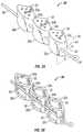
- FIGS. 3A and 3Bare perspective views of exemplary nucleus prostheses in accordance with some embodiments.
- FIGS. 4A and 4Bare top views of exemplary nucleus prostheses in accordance with some embodiments.
- FIG. 5is a perspective view of an insertion instrument in accordance with some embodiments.
- FIG. 6is an obverse cross-sectional view of an exemplary nucleus prosthesis being surgically implanted into an intervertebral disc in accordance with some embodiments.
- FIG. 7is an obverse cross-sectional view of an exemplary nucleus prosthesis being surgically implanted in accordance with some embodiments.
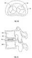
- FIG. 8is a cross-sectional view of a section of the human backbone after the surgical implantation of an exemplary nucleus prosthesis in accordance with some embodiments.
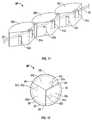
- FIG. 9is a perspective view of an exemplary nucleus prosthesis in accordance with some embodiments.
- FIG. 10is a top view of an exemplary nucleus prosthesis in accordance with some embodiments.
- FIG. 11is a perspective view of an exemplary nucleus prosthesis in accordance with some embodiments.
- FIG. 12is a top view of an exemplary nucleus prosthesis in accordance with some embodiments.
- FIGS. 13A and 13Bare a perspective view and a plan view, respectively, of man exemplary nucleus prosthesis in accordance with some embodiments.
- FIG. 14is a perspective view of an exemplary retainer for use with an nucleus prosthesis in accordance with some embodiments.
- FIG. 15is a perspective view of an exemplary nucleus prosthesis in accordance with some embodiments.
- FIG. 16is a perspective view of an exemplary nucleus prosthesis in accordance with some embodiments.
- FIG. 17is a perspective view of an exemplary nucleus prosthesis in accordance with some embodiments.
- FIG. 18is a cross-sectional view of the exemplary nucleus prosthesis of FIG. 17 in accordance with some embodiments.
- FIG. 19is another cross-sectional view of the exemplary nucleus prosthesis of FIG. 17 in accordance with some embodiments.
- FIG. 20is a perspective view of an exemplary nucleus prosthesis in accordance with some embodiments.
- FIG. 21is a perspective view of an exemplary nucleus prosthesis in accordance with some embodiments.
- FIG. 22is a perspective view of an exemplary enclosure in accordance with some embodiments.
- FIG. 23is a perspective view of an exemplary enclosure in accordance with some embodiments.
- FIG. 24is a perspective view of an exemplary nucleus prosthesis assembly in accordance with some embodiments.
- FIG. 25is an obverse cross-sectional view of an exemplary prosthesis being inserted into an enclosure in accordance with some embodiments.
- FIG. 26schematically depicts the insertion of a prosthesis in accordance with some embodiments.
- FIG. 27schematically depicts the insertion of a prosthesis in accordance with some embodiments.
- FIG. 28depicts an embodiment comprising spinal fixation components.
- FIG. 29depicts an embodiment comprising flexible spinal stabilization components.
- FIG. 30depicts an embodiment comprising multiple prostheses.
- FIG. 31depicts an embodiment configured to mitigate or impose lordosis.
- FIG. 1is a representative side view of a section 10 of a spine.
- the illustrated section 10shows an intervertebral disc 14 between two vertebrae 12 a and 12 b .
- disc 14includes annulus fibrosus 16 and nucleus pulposus 18 .
- annulus fibrosus 16ruptures, nucleus pulposus may emerge from the rupture and place pressure on spinal nerves (not illustrated).
- FIGS. 3A and 3Bdepict exemplary nucleus prostheses 30 in an open position in accordance with various embodiments.
- the implantationmay be arranged to alleviate the discomfort caused by a herniated disc (or other degenerative or pathological condition) while still providing a degree of mobility for the vertebrae.
- the prosthesis 30can be surgically implanted within the annulus fibrosus 16 , for example if the annulus fibrosus 16 remains sufficiently healthy and intact.
- the prosthesis 30can be employed to augment the remaining nucleus pulposus 18 .
- Various embodiments of the prosthesis 30can be employed to replace a nucleus pulposus 18 that has been completely extracted.
- the prosthesis 30can also be devised for insertion and deployment in an intervertebral disc space that has undergone a complete discectomy (complete removal of the intervertebral disc).
- the prosthesiswould be used as a fusion intersomatic cage and may comprise apertures or voids (or windows or recesses) as explained below.
- This embodiment of the prosthesis as a fusion cagemay also comprise osseous anchoring means, for example of known type, for fixing the prosthesis on the adjacent vertebrae before the fusion is complete.
- Prosthesis 30may also be employed to relieve back conditions other than a herniated disc; for example, the prosthesis 30 can be used to alleviate problems related to a hardening of annulus fibrosus 16 and/or dehydration of the nucleus pulposus, or other degenerative or pathological conditions.
- the prosthesis 30in various embodiments in which the prosthesis 30 is used as a fusion device, it can be deployed within remaining portions of the annulus fibrosus or deployed within the intervertebral disc space following a complete discectomy.
- the prosthesis 30can be configured to promote ingrowth of osseous tissue and can be disposed in the disc space to facilitate fusion of the vertebrae 12 a and 12 b.
- Prosthesis 30includes a plurality of segments 32 .
- FIGS. 3A and 3Beach respectively illustrates three segments 32 a , 32 b , and 32 c , but in alternate embodiments, prosthesis 30 may include any suitable number of segments from two on up.
- prosthesis 30may have two segments, four segments, five segments, six segments, and so on.
- Segments 32may be formed out of a rigid or semi-rigid material suitable for maintaining the spacing between the vertebrae 12 a and 12 b .
- segments 32may be formed out of a semi-rigid plastic material that is at least partially elastic to enable segments 32 to better absorb stresses placed on the segments after prosthesis 30 has been implanted into the annulus fibrosus 16 .
- segments 32may also be rigid in some or all portions of the segments 32 . Combinations of rigid and semi-rigid portions may be used in various embodiments of segments 32 to provide desired support properties.
- Segments 32may be linked together by at least one link.
- segments 32are linked by hinge 34 a (between segments 32 a and 32 b ) and hinge 24 b (between segments 32 b and 32 c ).
- Segments 32may also be linked together by one or more other linking elements like a flexible link, for example such as a ligament 36 .
- the ligament 36may take a secant path through one or more of the segments 32 , through a passage passing through the segment(s) or through a path following grooves along the segments. In other configurations, the ligament 36 may take other suitable paths (e.g., radial, annular, arcuate, incurvate, ascending, descending, weaving, etc.) through segments 32 .
- Ligament 36may be composed of synthetic fibers, such as Dacron® polyester fiber produced by E.I. du Pont de Nemours and Company of Wilmington, Del., other polymers or plastics, or other suitable materials. Other types of linkages may also be used to couple segments 32 , for example is discussed further below.
- Ligament 36may also include a closure element, for example such as loop 38 .
- Loop 38can be used during the surgical implantation of the prosthesis 30 , as described below.
- Other fastening or retaining devicesmay be employed as a closure element in place of a loop, such as for example a hook, catch, or clamp.
- segments 32may be disposed along ligament 36 in a serial line (i.e., one after another) from segment 32 c closest to loop 38 to segment 32 a furthest from loop 38 .
- the prosthesis 30In an open position, the prosthesis 30 will have a leading segment, such as for example segment 32 c , and a trailing segment, such as for example segment 32 a , with the designations “leading” and “trailing” established by the direction in which prosthesis 30 is implanted (see, e.g., FIGS. 6 , 25 ).
- prosthesis 30in an open position, has a cross-sectional area 40 generally bounded in width by the width 42 of the segments 32 and generally bounded in height by a vertical height 44 of the segments 32 .
- Prosthesis 30may have any suitable height 44 or width 42 .
- the height 44 and width 42 of segments 32can be selected based on a height and width of a patient's intervertebral disc 14 or the intervertebral disc space.
- Segments 32are shaped such that when the prosthesis 30 is in a closed position (see FIGS. 4A , 4 B, 7 , 10 , and 12 showing almost closed positions, and FIGS. 15 and 30 showing closed positions), segments 32 form a shape suitable for supporting the vertebrae 12 a and 12 b .
- Suitable shapesmay vary depending on the anatomy of the patient and on the intended deployment of the prosthesis 30 , for example deployment within the annulus fibrosus, deployment in an intervertebral disc space that has undergone a complete discectomy, deployment as a fusion device, or deployment to correct or impose a lordosis or kyphosis condition.
- a disc shapeThis designation concerns the shape of the nucleus with respect to the intervertebral disc.
- a disc shapemay be in the form of a straight and flat cylinder as shown on the figures.
- other shapesmay be used, for example a generalized cylinder, i.e., a shape defined by sweeping a variable cross-section along an axis such as a line or a more general space curve, bounded on both sides by surfaces that may be flat, convex, concave, or a combination of the foregoing.
- a straight cylinderis defined by a circular base and a straight height
- a generalized cylindermay be defined by a base of any curved or polygonal shape and a curved or straight height.
- the instant nucleus prosthesismay have any shape of these types of generalized cylinder.
- the vertebral contact surfaces of the generalized cylindrical shapesmay have edges taking any suitable shape (e.g., a circle, an ellipse, an oval, an oblong, an egg shape, a polygon, etc.).
- a disc shapealternatively may be in the form of a generalized ellipsoid, a polyhedron, a generalized toroid, or another shape.
- the disc shape formed by segments 32 when the prosthesis 30 is in a closed positionmay be solid or may be generally hollow.
- segments 32each have a wedge, pie, or tapered shape, but other shapes may be used.
- Various embodimentsmay be feature chamfered, tapered, or beveled edges to mitigate damage to the vertebral surfaces.
- the embodiments illustrated in FIGS. 3A and 4Ahave chamfered edges between the sidewalls and the upper and lower surfaces of the segments.
- the internal face 46 of the leading segmentmay have upper, lower, and/or outer edges that are chamfered, for example as illustrated in FIGS. 3A and 4A , to facilitate closing of the prosthesis 30 and mitigate damage to surrounding tissue during the closing.
- the disc shape formed by segments 32 when the prosthesis 30 is in a closed positionmay have one or more apertures or voids along either or both of its vertebral contact surfaces and/or along one or more external and/or internal walls or faces of one or more of the segments of the prosthesis. These apertures may consist in blind holes or holes passing through the segments.
- FIG. 3Adepicts an embodiment in which apertures or voids 35 are disposed along the vertebral contact surfaces 33 a , 33 b , and 33 c . In this embodiment, the apertures or voids 35 are relatively small cylindrical holes.
- the voids 35can be devised to accommodate bone ingrowth from the adjacent vertebra, which may promote stability of the prosthesis 30 within the annulus fibrosus 16 or within the intervertebral disc space. Apertures or voids can also be configured to promote fusion.
- FIG. 3Bdepicts an embodiment of a prosthesis 30 having numerous apertures 35 configured for bone ingrowth to promote fusion of the vertebrae 12 a and 12 b .
- the apertures 35 on the upper and lower surfaces of the segmentsmay be connected, so that bone ingrowth can extend continuously from the upper vertebra to the lower vertebra.
- the aperturescan connect along the internal faces of the segments to promote contiguous bone ingrowth throughout the prosthesis 30 .
- FIGS. 3A and 3Bare substantially hollow, but other embodiments may employ different configurations and extents of the apertures or voids. Bone ingrowth for the embodiments of FIGS. 3A and 3B , as well as other embodiments, can be promoted using osseous tissue or natural or synthetic substitutes for osseous tissue, or by other techniques.
- FIG. 4depicts prosthesis 30 in an almost closed position in accordance with various embodiments.
- segments 32 a , 32 b , and 32 c of such embodimentswill have a disc shape generally in the form of a cylinder.
- the segments 32fold around the hinges 34 a and 34 b such that a face 46 of a segment 32 is substantially juxtaposed to a face 46 of an adjacent segment 32 .
- a face 46 of segment 32 ais adjacent to a face 46 of segment 32 c .
- the first segment in the series of segments 32is generally adjacent to the last segment in the series.
- FIG. 5depicts an insertion instrument in accordance with various embodiments.
- the insertion instrumentis a guide configured as a chute 50 having a channel 51 extending along the length of the chute 50 .
- the insertion instrumenthas an open end 52 configured to receive a prosthesis, such as, for example, a hinged prosthesis 30 as illustrated.
- the channel 51preferably has an internal cross section complementary to the cross-sectional profile 40 of the prosthesis (i.e., complementary to the transversal section of the prosthesis in an open position).
- an internal cross section of the insertion instrument complementary to the cross-sectional profile 40 of the prosthesiswill tend to keep the segments of the prosthesis, such as segments 32 a , 32 b , and 32 c of the illustrated prosthesis 30 , in good alignment while the prosthesis traverses the channel to reach the insertion point (i.e., within the annulus fibrosus or within the intervertebral disc space in the case of a complete discectomy).
- a divertersuch as the curved deflector 53 , optionally may be disposed at the end of insertion instrument 50 . The diverter may have a flexibility adapted to facilitate closure of prosthesis segments while still facilitating withdrawal of the insertion instrument.
- the divertermay have selectable flexibility, for example by having setting for insertion of the prosthesis in which the diverter is relatively rigid while having another setting for withdrawal of the insertion instrument in which the diverter is relatively flexible.
- the deflectormay have multiple articulated segments along the insertion direction through which a common conduit passes.
- a “J” shaped spring steel splinehaving an end with an appropriate curvature may be forced into a straight position and passed along the length of the insertion tool through a conduit into the conduit of the deflector segments.
- the deflectorWhen the spline is fully inserted through the insertion tool conduit and the common conduit through the articulated deflecting segments, the deflector would tend to maintain the appropriate curvature for insertion of the prosthesis. When the prosthesis has been inserted, the spline could be withdrawn fully from the conduits, releasing conformal forces on the articulated deflecting segments and allowing them to articulate and align with each other during withdrawal of the insertion instrument.
- a positionermay be used during insertion of the prosthesis.
- the positioner depicted in FIG. 5is configured as a rod 54 .
- the positionermay be configured with a control, for example such as the handle or knob 55 of the embodiment illustrated in FIG. 5 .
- the positionermay have a coupler, for example such as the notch 56 illustrated in FIG. 5 .
- the notch 56has a surface-complementary to the trailing end of a prosthesis segment, but other coupling means may be used.
- the positionermay also have a transit for a linking element or a part thereof.
- the embodiment illustrated in FIG. 5has a transit configured as a channel 57 , through which an end portion of a ligament 36 can extend.
- a positionermay be used to urge a prosthesis along an insertion instrument.
- the positionermay be used to maintain the nucleus prosthesis within the annulus fibrosus 16 or within the intervertebral disc space while a linking element, such as ligament 36 , is employed to close the prosthesis, and may also be used to further urge the prosthesis into proper position during the closure operation.
- FIG. 6illustrates a technique that may be used to surgically implant a nucleus prosthesis 30 into an annulus fibrosus 16 in accordance with various embodiments.
- an insertion instrumentfor example such as a chute or tube 50
- a surgical incision 20 in the annulus fibrosus 16into the site of the nucleus pulposus 18 .
- Some or all of nucleus pulposus 18may be removed, through chute 50 (removal not shown) or otherwise.
- prosthesis 30in an open position, is fed through chute 50 into the annulus fibrosus 16 with loop 38 entering first.
- the cross-sectional area of the surgical incisionmay be generally the same as the cross-sectional profile 40 even though, as described below, prosthesis 30 in a closed position has a cross-sectional area larger than the profile 40 .
- FIG. 7illustrates prosthesis 30 in an almost closed position during the surgical implantation of prosthesis 30 within the annulus fibrosus 16 in accordance with various embodiments.
- loop 38 and segment 32 cmake contact with a surface of annulus fibrosus 16 causing segment 32 c and segment 32 b to fold about hinge 34 b .
- segment 32 b and segment 32 awill subsequently fold about hinge 34 a .
- loop 38can engage the other end of ligament 36 (near segment 32 a ).
- prosthesis 30can be urged into a closed position by pulling on the end of the ligament 36 opposite the loop 38 .
- Engagement of loop 38 with the other end of ligament 36can be configured to cause ligament 36 to tighten around segments 32 a , 32 b , and 32 c , and to urge the prosthesis 30 into a closed position.
- the insertion instrument 50may of course be used here to facilitate the removal of the prosthesis, as detailed below.
- This tighteningmay be aided by one or more lubricants on ligament 36 .
- face 46 a of segment 32 a and face 46 c of segment 32 care substantially apposed.
- a positioner 54may be used to hold the prosthesis 30 in position while ligament 36 is tightened.
- loop 38can be permanently fastened to maintain prosthesis 30 in a closed position.
- other techniquescan be used to keep prosthesis 30 in a closed position.
- ligament 36can be trimmed, chute 50 can be removed, and annulus fibrosus 16 can be closed.
- the surgical incisionwill be sized so that the prosthesis 30 in a closed position will not fit through the surgical incision, although in some embodiments, prosthesis 30 can be returned to an open position for removal via the surgical incision.
- FIG. 8illustrates the section 10 of the spine after a prosthesis 30 has been surgically implanted into the annulus fibrosus 16 .
- a prosthesis 30is placed within annulus fibrosus 16 to facilitate vertebral support and shock absorption.
- FIG. 8illustrates a non-fusion installation of a nucleus prosthesis 30 inside annulus librosus 16 .
- any of the prostheses described hereincould alternatively be reconfigured for use as a fusion device within the annulus fibrosus 16 or within the intervertebral disc space that has undergone a complete discectomy.
- FIG. 9illustrates another embodiment of prosthesis 30 .
- prosthesis 30includes segments 70 a , 70 b , and 70 c coupled together via hinges 34 a and 34 b and ligament 36 .
- Segments 70each include respective male interlocking elements 72 and female interlocking elements 74 .
- FIG. 10a top view of this embodiment of prosthesis 30 , interlocking elements 72 and 74 interlock with each other when prosthesis 30 is in a closed position.
- male interlocking elements 72are formed out of the same elastic material as segments 70 .
- Interlocking elements 72 and 74may be configured to prevent both horizontal and vertical movement between individual segments 70 when this embodiment of prosthesis 30 is in a closed position, or may be configured to allow limited relative movements of segments 70 horizontally and/or vertically.
- FIG. 11illustrates a perspective view of another embodiment of prosthesis 30 in which the individual segments of the prosthesis 30 are able to move vertically with respect to one another when prosthesis 30 is in a closed position.
- This embodiment of prosthesis 30includes segments 90 a , 90 b , and 90 c linked together via ligament 36 .
- the ligament 36traverses through bores 96 that take a secant path through each segment 90 a , 90 b , and 90 c , and through optional grooves 98 along the edges of the segments.
- the grooves 98could extend around one or more of the segment 90 a , 90 b , and 90 c in lieu of holes 96 .
- Other combinations of bores 96 and/or grooves 98will be apparent to those of skill in the art after appreciating this disclosure.
- other linkagesmay also be used to couple segments 90 together.
- the segments 90each include male interlocking elements 92 and female interlocking elements 94 .
- female interlocking elements 94are longer in the vertical direction than the male interlocking elements 92 . This feature enables the male interlocking elements 92 to slide within the female interlocking elements 94 , permitting vertical movements of segments 90 with respect to one another.
- other suitable mechanismmay be employed for interlocking segments 90 while providing relative vertical movements of the segments 90 .
- jointsare formed by interlocking elements 92 and 94 engaging each other when prosthesis 30 is in a closed position.
- the male interlocking elements 92may slide vertically within the female interlocking elements 94 .
- the male interlocking elements 92may be configured as pins
- the female interlocking elements 94may be configured as channels have an interior shape complementary to the external shape of the pins.
- the interlocking elements 92 and 94are configured to enable vertical movement between individual segments 90 when embodiments of prosthesis 30 such as this are in a closed position.
- the male interlocking elements 92are formed out of the same elastic material as segments 90 .
- FIGS. 13A and 13Billustrate another embodiment of prosthesis 30 .
- This embodiment of prosthesis 30includes segments 110 a , 110 b , and 110 c .
- Each of the segments 110includes a first elasticity region 112 and a second elasticity region 114 in which the first and second elasticity regions are composed of materials with different constants of elasticity.
- segments 110 a , 110 b , and 110 cmay alternatively exhibit an elasticity gradient through portions of segments 110 a , 110 b , and 110 c . Segments having different elasticity regions or an elasticity gradient, similarly may be deployed in various other embodiments.
- segments 110 a , 110 b , and 110 care linked together with two ligaments 36 a and 36 b .
- ligaments 36 a and 36 bare used to urge segments 110 into a closed position, and may be used to maintain the prosthesis 30 in a closed position.
- ligaments 36 a and 36 bare woven through the segments 110 , but other suitable ligament structures can be used (e.g., a single ligament traversing a secant path through bores in segments 110 or grooves along the sidewalls of segments 110 ).
- ligaments 36 a and 36 bmay be lubricated to facilitate their movement with respect to segments 110 .
- the linking elementsmay be devised to accommodate the shapes and irregularities of the surfaces of the adjacent vertebrae.
- the ligaments 36 a and 36 bmay be configured with an elasticity that will allow the individual segments of the prosthesis 30 to move vertically with respect to one another when prosthesis 30 is in a closed position.
- the ligaments 36 a and 36 bmay be configured with an elasticity that will allow the segments 110 a , 110 b , and 110 c to spread apart to adapt to any protuberance on a surface of either or both of the adjacent vertebrae.
- Various embodimentsmay have one or more segments in which the height of a segment varies among different portions of the segment. Such variations may accommodate various shapes of the surfaces of the adjacent vertebrae.
- segments 110 a , 110 b , and 110 c of the embodiments illustrated in FIGS. 13A , 13 B, and 15have portions 112 a , 112 b , and 112 c that are higher than portions 114 a , 114 b , and 114 c.
- FIGS. 13A and 13Bincludes retainers in the form of the stoppers 116 a and 116 b .
- the stoppers 116 a and 116 bare disposed along ligaments 36 a and 36 b , respectively, and are sized to lodge into channels 120 a and 120 b , respectively (see FIG. 15 ) to retain or lock prosthesis 30 in a closed position. Stoppers can be used to secure each end of ligaments 36 a and 36 b , or one end of each ligament may be secured with a stopper 116 and the other directly fastened to a segment, such as shown for example with respect to segment 110 c in FIGS. 13B and 15 .
- FIG. 14An enlarged view of a stopper 116 in accordance with various embodiments is shown in FIG. 14 .
- Other suitable types of stoppers, plugs, clips, latches, catches, locks, pawls, and dogsmay also be employed as retainers.
- retainersmay be used to lock other described prosthesis embodiments in addition to the one illustrated in FIGS. 13A , 13 B, and 15 .
- FIG. 16is a perspective view of an nucleus prosthesis 130 in accordance with various embodiments.
- Prosthesis 130includes segments 132 a , 132 b , and 132 c , ligament 134 , and strip 136 (comprising, in some embodiments, a track for the sliding of hinges as described later).
- Segments 132may be substantially similar in material and shape to segments 32 , 70 , 90 , and 110 described above. In other words, segments 132 are shaped such that when closed together (see FIG. 20 ), segments 132 form a disc shape, as described above. Further, the height and width of segments 132 may be selected with respect to the dimensions of the patient's disc 14 or the intervertebral disc space.
- Ligament 134is substantially similar to ligament 36 , also described above. As shown, ligament 134 may be threaded lengthwise back and forth between the ends of strip 136 .
- the strip 136preferably is configured to bend or flex around segments 132 as segments 132 are brought together into a closed position.
- the strip 136can comprise a flexible material, with an elasticity similar to or different from the elasticity of the segments or can have a gradient of elasticity.
- the stripcan have recesses or voids, for example such as notches 38 shown in FIG. 16 , that facilitate bending or flexing of the strip 136 .
- Notches 38optionally may open along the inward side of the strip as illustrated in FIG. 16 , or open along the outward side of the strip. Optionally, the notches may not open along the inward or outward sides of the strip.
- the strip 136also may be formed from a material having sufficient flexibility to accommodate the required bending or flexing without any notches or recesses. In various embodiments, strip 136 is bent by tightening the ligament 134 .
- FIG. 17is a partial perspective view of another embodiment of prosthesis 130 .
- ligament 134is omitted from FIG. 17 .
- Segments 132 a , 132 b , and 132 care linked together by hinges 140 b and 140 c and are coupled to strip 136 by hinges 140 a , 140 b , 140 c , and 140 d .
- each of the hinges 140 b and 140 cis coupled to one or more of the segments 132 to form a serial line of segments.
- Each of the hinges 140also may have a pin that rides within a groove 142 of strip 136 , for example forming a track guiding the hinges.
- hinge 140 bis coupled between segments 132 a and 132 b and rides in groove 142
- hinge 140 cis coupled between segments 132 b and 132 c and rides in groove 142
- Hinge 140 ais coupled to segment 132 a alone
- hinge 140 dis coupled to segment 132 c alone
- each of hinges 140 a and 140 drides within groove 142
- other mechanismmay be employed to couple segments 132 to strip 136 .
- FIGS. 18 and 19Cross-sectional views along the cut-lines shown in FIG. 17 are shown in FIGS. 18 and 19 .
- FIGS. 18 and 19highlight the spatial relationships between segments 132 , hinges 140 , and groove 142 .
- FIG. 18illustrates a cross-sectional view of prosthesis 130 through one of the segments 132
- FIG. 19illustrates a cross-sectional view of prosthesis 130 through one of the hinges 140 .
- hinge 140includes a pin 150 that rides within groove 142 .
- segments 132are able to move freely within groove 142 .
- one or more of segments 132each may be equipped with a pin 150 coupled to the strip 136 .
- hinges 140may not have pins, and pins deployed with segments 132 may be the sole means of retaining the segments 132 with the strip 136 .
- Other forms of retainersmay be used instead of pins; for example, either or both of the segments 132 and the hinges 140 may be configured with integral or attached dovetail extensions that fit a dovetail channel in the strip 136 .
- Other forms of extensionsmay also be used as a retainer, such as for example “T” shaped extensions integral with or attached to either or both of the segments 132 and the hinges 140 , which fit a “T” shaped channel in the strip 136 .
- prosthesis 130is configured to close so that segments 132 form a disc shape.
- prosthesis 130may be surgically introduced into the annulus fibrosus 16 in an open position and then bent to a closed position as it enters the disc.
- prosthesis 130is bent by pulling on ligament 134 .
- FIG. 20illustrates prosthesis 130 in a closed position.
- strip 136encircles segments 132 holding them in a closed position.
- Prosthesis 130may then be secured in a closed position by securing ligament 134 so that it holds the ends of the strip in proximity with each other.
- FIG. 21illustrates an alternate embodiment of prosthesis 130 in which strip 136 generally encloses segments 132 .
- the upper and lower surfaces of strip 136may extend over segments 132 .
- the groove 142may also be enlarged to enclose segments 132 .
- FIG. 22depicts an enclosure 162 that may be used with various embodiments of the prosthesis.
- Enclosure 162may be configured in a disc shape and may be configured to enclose a prosthesis, such as prosthesis 30 or 130 or another suitable nucleus prosthesis.
- Each of the upper and lower surfaces of enclosure 162can be generally flat, convex, or concave throughout the surfaces or in selected portions of the surfaces (as mentioned previously for the prosthesis).
- Enclosure 162may be made from any suitable biocompatible material, such as Dacron® polyester fiber, other polymers or plastics, or other suitable materials.
- a thickness, weave, or elasticity of enclosure 162is selected to produce a desired stiffness.
- the stiffness in various embodimentsmay be sufficient for the enclosure 162 to have a normal shape, such as a disc shape, when external forces are not acting on the enclosure 162 .
- the enclosure 162will have an elasticity and/or stiffness that tend to return the enclosure 162 to its normal shape when forces deforming the enclosure 162 cease.
- an enclosure 162may not have a well defined shape, for example in embodiments of an enclosure comprising bag, such as a fabric sack for example.
- FIG. 24is a perspective view of a prosthesis assembly 160 in accordance with various embodiments.
- Prosthesis assembly 160includes an enclosure 162 , such as shown in FIG. 23 , that holds a nucleus prosthesis, for example such as nucleus prosthesis 30 or 130 as described above, and a ligament 164 that can be used to close enclosure 162 .
- FIG. 25illustrates a surgical implantation of prosthesis assembly 160 in accordance with some embodiments.
- the enclosure 162may be coupled with an insertion instrument, for example such as the illustrated chute 50 .
- the enclosure and the insertion instrumentmay be provided to the surgeon assembled in various embodiments.
- enclosure 162is fitted onto one end of chute 50 and may be placed into the annulus fibrosus 16 .
- the enclosuremay be provided separately from the insertion instrument.
- an insertion instrumentsuch as chute 50 is put into place and an enclosure 162 is compressed or folded and fed through the chute 50 into the nucleus area.
- enclosure 162may return generally to its normal shape.
- FIG. 25depicts a particular embodiment of prosthesis 30
- any other suitable prosthesis configurationmay be used, such as for example prosthesis 130 or any variants of prostheses 30 and 130 .
- Enclosure 162preferably will have an interior compatible with the closed position of the nucleus prosthesis 30 .
- the enclosure 162may be fitted onto an end of the chute 50 and thus maintained open while it is placed inside the annulus or the disc space, so as to facilitate the entrance of the prosthesis inside the enclosure afterwards. As illustrated in FIG.
- the prosthesis 30is fed in an open position through chute 50 in direction 170 into the enclosure 162 , which is now inside the annulus fibrosus 16 .
- As prosthesis 30 enters the enclosure 162it folds until the prosthesis 30 is in a closed position.
- the prosthesis 30may also be tightened into a closed position with the ligament 36 .
- enclosure 162may be closed with ligament 164 , for example by pulling it.
- ligament 164may be trimmed, chute 50 removed, and the surgical incision closed.
- prosthesis assembly 160may be employed as a replacement for a disc 14 that been removed during a complete discectomy.
- an insertion instrumentmay have advantageous.
- an insertion instrumentmay be used to hold the enclosure open and/or in place during the insertion of the prosthesis.
- FIG. 26illustrates an embodiment of an enclosure comprising a fabric sack 162 .
- the end of the chute 50holds the enclosure 162 open and retains the enclosure 162 in place during insertion of the prosthesis.
- the prosthesismay be passed through channel 51 with segments 32 a , 32 b , and 32 c arranged in a serial line to enter the enclosure 162 .
- segment 32 cencounters the deflector 53 first, causing the segment to turn and commencing the closure of the segments 32 a , 32 b , and 32 c .
- lateral manipulation of the end of the leading segmentmay facilitate closure, for example as illustrated in FIG. 26 in which the end of segment 32 c is moved toward the outer lateral wall of the channel 51 comprising the deflector 53 (which is the top wall of channel 51 in the orientation shown in FIG. 26 ), causing the hinge between segments 32 c and 32 b to move toward the inner lateral wall of the channel 51 (which is the bottom wall of channel 51 in the orientation shown in FIG. 26 ), which in turn causes the hinge between segments 32 b and 32 a to move toward the upper wall of the channel 51 , thereby placing segments 32 b and 32 a in a better position for closure of those segments as shown in FIG. 27 .
- the prosthesismay be deployed with other spinal stabilization structures.
- FIG. 28depicts an embodiment in which the prosthesis 30 is configured as a fusion device and is implanted within nucleus fibrosus 16 as discussed above, although other prosthesis embodiments and implantation methods may be used.
- a posterior spinal stabilization devicecan be used to provide additional stability to the intervertebral alignment.
- a pedicle screw 81is implanted in each of the vertebrae 12 a and 12 b .
- the pedicle screws 81advantageously can be configured as described in U.S. application Ser. No. 10/473,999 filed Apr. 12, 2004 (FR2823093), or U.S. application Ser. No.
- FIG. 29depicts an embodiment using a vertebral support device as described in U.S. application Ser. No. 11/672,745 filed Feb. 8, 2007, (FR 0611198) which is commonly owned by the assignee of the present application, and which is incorporated herein by reference.
- a pedicle screw 81is implanted in each of the vertebrae 12 a and 12 b .
- a linking element 83comprises a dampening element 84 and rigid elements 85 articulated by the dampening element 84 .
- Each of the rigid elements 85is fixed to one of the pedicle screws 81 , respectively.
- the vertebral support deviceprovides flexible articulation of the rigid elements 85 , which may provide some freedom of movement to the vertebrae 12 a and 12 b .
- the dampening element 84accommodates the stresses experienced by the linking element 83 during these movements, and tends to return the vertebrae 12 a and 12 b to an intended configuration.
- multiple prosthesesmay be deployed within the annulus fibrosus 16 or the intervertebral disc space.
- FIG. 30depicts an embodiment using two prostheses 30 appropriately sized for insertion within the annulus fibrosus or for deployment within the intervertebral disc space following a complete discectomy.
- Other embodimentsmay use more than two prostheses.
- Other prosthesis embodimentsmay be used, and combinations of prosthesis embodiments may be used.
- An enclosuremay be used with one, several, or all of the various prostheses used in a multiple-prosthesis embodiments.
- Multiple-prosthesis embodimentsalso may be used with other spinal stabilization structures, such as those discussed above.
- FIG. 31depicts an embodiment of a nucleus prosthesis 30 implanted within the annulus fibrosus and configured to mitigate or impose lordosis.
- the upper and lower surfaces of the depicted prosthesis 30are angled so that the anterior portion of the prosthesis 30 is thinner than the posterior portion.
- a kyphotic conditioncould be mitigated or imposed by configuring a prosthesis having an anterior portion that is thicker than the posterior portion.
- references herein to surfaces or other structures as “upper,” “top,” “lower,” “bottom,” or having a “height,” “width,” or “length,” and directional references such as “horizontal” and “vertical,”are generally arbitrary and for convenience only, and those of skill in the art will recognize after appreciating this disclosure that such designations appropriately may be reoriented in particular embodiments.
- the described embodimentsare illustrative only and are not restrictive, and the scope of the invention is defined solely by the following claims.
Landscapes
- Health & Medical Sciences (AREA)
- Engineering & Computer Science (AREA)
- Biomedical Technology (AREA)
- Orthopedic Medicine & Surgery (AREA)
- Neurology (AREA)
- Transplantation (AREA)
- Life Sciences & Earth Sciences (AREA)
- General Health & Medical Sciences (AREA)
- Veterinary Medicine (AREA)
- Heart & Thoracic Surgery (AREA)
- Public Health (AREA)
- Animal Behavior & Ethology (AREA)
- Cardiology (AREA)
- Vascular Medicine (AREA)
- Oral & Maxillofacial Surgery (AREA)
- Physical Education & Sports Medicine (AREA)
- Surgery (AREA)
- Nuclear Medicine, Radiotherapy & Molecular Imaging (AREA)
- Medical Informatics (AREA)
- Molecular Biology (AREA)
- Prostheses (AREA)
Abstract
Description
Claims (27)
Priority Applications (2)
| Application Number | Priority Date | Filing Date | Title |
|---|---|---|---|
| US14/159,161US9526622B2 (en) | 2007-06-15 | 2014-01-20 | Nucleus prosthesis |
| US15/391,305US20170172761A1 (en) | 2007-06-15 | 2016-12-27 | Nucleus Prosthesis |
Applications Claiming Priority (2)
| Application Number | Priority Date | Filing Date | Title |
|---|---|---|---|
| FR0704326AFR2917287B1 (en) | 2007-06-15 | 2007-06-15 | INTERVERTEBRAL PROSTHESIS |
| FR0704326 | 2007-06-15 |
Related Child Applications (1)
| Application Number | Title | Priority Date | Filing Date |
|---|---|---|---|
| US14/159,161DivisionUS9526622B2 (en) | 2007-06-15 | 2014-01-20 | Nucleus prosthesis |
Publications (2)
| Publication Number | Publication Date |
|---|---|
| US20080312743A1 US20080312743A1 (en) | 2008-12-18 |
| US8632591B2true US8632591B2 (en) | 2014-01-21 |
Family
ID=38982740
Family Applications (3)
| Application Number | Title | Priority Date | Filing Date |
|---|---|---|---|
| US11/874,144Expired - Fee RelatedUS8632591B2 (en) | 2007-06-15 | 2007-10-17 | Nucleus prostheses |
| US14/159,161Expired - Fee RelatedUS9526622B2 (en) | 2007-06-15 | 2014-01-20 | Nucleus prosthesis |
| US15/391,305AbandonedUS20170172761A1 (en) | 2007-06-15 | 2016-12-27 | Nucleus Prosthesis |
Family Applications After (2)
| Application Number | Title | Priority Date | Filing Date |
|---|---|---|---|
| US14/159,161Expired - Fee RelatedUS9526622B2 (en) | 2007-06-15 | 2014-01-20 | Nucleus prosthesis |
| US15/391,305AbandonedUS20170172761A1 (en) | 2007-06-15 | 2016-12-27 | Nucleus Prosthesis |
Country Status (14)
| Country | Link |
|---|---|
| US (3) | US8632591B2 (en) |
| EP (1) | EP2170226B1 (en) |
| JP (1) | JP5574958B2 (en) |
| KR (2) | KR20100024417A (en) |
| CN (2) | CN101784240B (en) |
| AU (1) | AU2008263569B2 (en) |
| BR (1) | BRPI0812536A2 (en) |
| CA (1) | CA2690550C (en) |
| ES (1) | ES2570608T3 (en) |
| FR (1) | FR2917287B1 (en) |
| MX (1) | MX2009013712A (en) |
| RU (1) | RU2489119C2 (en) |
| WO (1) | WO2008152501A2 (en) |
| ZA (1) | ZA200908676B (en) |
Cited By (16)
| Publication number | Priority date | Publication date | Assignee | Title |
|---|---|---|---|---|
| US8974497B2 (en) | 2006-12-21 | 2015-03-10 | Ldr Medical | Vertebral support device |
| US9445918B1 (en) | 2012-10-22 | 2016-09-20 | Nuvasive, Inc. | Expandable spinal fusion implants and related instruments and methods |
| US9480574B2 (en) | 2013-03-14 | 2016-11-01 | Benvenue Medical, Inc. | Spinal fusion implants and devices and methods for deploying such implants |
| US9561115B2 (en) | 2011-09-20 | 2017-02-07 | The University Of Toledo | Expandable inter-vertebral cage and method of installing same |
| US9642712B2 (en) | 2007-02-21 | 2017-05-09 | Benvenue Medical, Inc. | Methods for treating the spine |
| US9700425B1 (en) | 2011-03-20 | 2017-07-11 | Nuvasive, Inc. | Vertebral body replacement and insertion methods |
| US9913728B2 (en)* | 2013-03-14 | 2018-03-13 | Quandary Medical, Llc | Spinal implants and implantation system |
| US20180271659A1 (en)* | 2015-01-09 | 2018-09-27 | Formae, Inc. | Rigid segmented flexible anchors |
| US10188528B2 (en) | 2007-02-16 | 2019-01-29 | Ldr Medical | Interveterbral disc prosthesis insertion assemblies |
| US10350088B2 (en) | 2005-06-29 | 2019-07-16 | Ldr Medical | Instrumentation and methods for inserting an intervertebral disc prosthesis |
| US11224453B2 (en) | 2014-07-08 | 2022-01-18 | Spinal Elements, Inc. | Apparatus and methods for disrupting intervertebral disc tissue |
| US11471145B2 (en) | 2018-03-16 | 2022-10-18 | Spinal Elements, Inc. | Articulated instrumentation and methods of using the same |
| US11564811B2 (en) | 2015-02-06 | 2023-01-31 | Spinal Elements, Inc. | Graft material injector system and method |
| US11583327B2 (en) | 2018-01-29 | 2023-02-21 | Spinal Elements, Inc. | Minimally invasive interbody fusion |
| US11771483B2 (en) | 2017-03-22 | 2023-10-03 | Spinal Elements, Inc. | Minimal impact access system to disc space |
| US20230355405A1 (en)* | 2022-05-04 | 2023-11-09 | NovApproach Spine, LLC | Interbody cage device and method for performing spinal surgical procedures |
Families Citing this family (119)
| Publication number | Priority date | Publication date | Assignee | Title |
|---|---|---|---|---|
| FR2897259B1 (en) | 2006-02-15 | 2008-05-09 | Ldr Medical Soc Par Actions Si | INTERSOMATIC TRANSFORAMINAL CAGE WITH INTERBREBAL FUSION GRAFT AND CAGE IMPLANTATION INSTRUMENT |
| US7267687B2 (en)* | 2001-10-02 | 2007-09-11 | Rex Medical, L.P | Spinal implant and method of use |
| US8236029B2 (en) | 2004-08-11 | 2012-08-07 | Nlt Spine Ltd. | Devices for introduction into a body via a substantially straight conduit to for a predefined curved configuration, and methods employing such devices |
| US20060036241A1 (en) | 2004-08-11 | 2006-02-16 | Tzony Siegal | Spinal surgery system and method |
| WO2006034436A2 (en) | 2004-09-21 | 2006-03-30 | Stout Medical Group, L.P. | Expandable support device and method of use |
| WO2006058221A2 (en) | 2004-11-24 | 2006-06-01 | Abdou Samy M | Devices and methods for inter-vertebral orthopedic device placement |
| WO2007121320A2 (en)* | 2006-04-12 | 2007-10-25 | Spinalmotion, Inc. | Posterior spinal device and method |
| EP2023864B1 (en) | 2006-05-01 | 2019-07-10 | Stout Medical Group, L.P. | Expandable support device |
| US20070260314A1 (en)* | 2006-05-02 | 2007-11-08 | Ashok Biyani | Transforaminal lumbar interbody fusion cage |
| CA2668655A1 (en) | 2006-11-16 | 2008-05-29 | Rex Medical, L.P. | Spinal implant and method of use |
| WO2008070863A2 (en) | 2006-12-07 | 2008-06-12 | Interventional Spine, Inc. | Intervertebral implant |
| US9039768B2 (en) | 2006-12-22 | 2015-05-26 | Medos International Sarl | Composite vertebral spacers and instrument |
| US20100191333A1 (en)* | 2007-06-08 | 2010-07-29 | Morrison Iii Thomas J | Load-bearing spinal interbody device |
| FR2916956B1 (en) | 2007-06-08 | 2012-12-14 | Ldr Medical | INTERSOMATIC CAGE, INTERVERTEBRAL PROSTHESIS, ANCHORING DEVICE AND IMPLANTATION INSTRUMENTATION |
| FR2917287B1 (en) | 2007-06-15 | 2010-09-03 | Ldr Medical | INTERVERTEBRAL PROSTHESIS |
| US8900307B2 (en) | 2007-06-26 | 2014-12-02 | DePuy Synthes Products, LLC | Highly lordosed fusion cage |
| EP2208481B1 (en)* | 2007-07-27 | 2016-12-28 | R Tree Innovations, LLC | Inter-Body Implantation System |
| WO2009019669A1 (en)* | 2007-08-09 | 2009-02-12 | Nonlinear Technologies Ltd. | Device and method for spinous process distraction |
| US9101491B2 (en)* | 2007-12-28 | 2015-08-11 | Nuvasive, Inc. | Spinal surgical implant and related methods |
| EP2237748B1 (en) | 2008-01-17 | 2012-09-05 | Synthes GmbH | An expandable intervertebral implant |
| US8795365B2 (en)* | 2008-03-24 | 2014-08-05 | Warsaw Orthopedic, Inc | Expandable devices for emplacement in body parts and methods associated therewith |
| US8936641B2 (en) | 2008-04-05 | 2015-01-20 | DePuy Synthes Products, LLC | Expandable intervertebral implant |
| US9364338B2 (en)* | 2008-07-23 | 2016-06-14 | Resspond Spinal Systems | Modular nucleus pulposus prosthesis |
| US20100211176A1 (en) | 2008-11-12 | 2010-08-19 | Stout Medical Group, L.P. | Fixation device and method |
| WO2010056895A1 (en) | 2008-11-12 | 2010-05-20 | Stout Medical Group, L.P. | Fixation device and method |
| US9526620B2 (en) | 2009-03-30 | 2016-12-27 | DePuy Synthes Products, Inc. | Zero profile spinal fusion cage |
| US9408715B2 (en) | 2009-04-15 | 2016-08-09 | DePuy Synthes Products, Inc. | Arcuate fixation member |
| US8641766B2 (en) | 2009-04-15 | 2014-02-04 | DePuy Synthes Products, LLC | Arcuate fixation member |
| ES2563172T3 (en) | 2009-07-09 | 2016-03-11 | R Tree Innovations, Llc | Flexible intersomatic implant |
| US20110029085A1 (en)* | 2009-07-31 | 2011-02-03 | Warsaw Orthopedic, Inc. | Flexible spinal implant |
| US20110029083A1 (en)* | 2009-07-31 | 2011-02-03 | Warsaw Orthopedic, Inc. | Flexible Spinal Implant |
| US9028553B2 (en) | 2009-11-05 | 2015-05-12 | DePuy Synthes Products, Inc. | Self-pivoting spinal implant and associated instrumentation |
| US8764806B2 (en) | 2009-12-07 | 2014-07-01 | Samy Abdou | Devices and methods for minimally invasive spinal stabilization and instrumentation |
| US9393129B2 (en) | 2009-12-10 | 2016-07-19 | DePuy Synthes Products, Inc. | Bellows-like expandable interbody fusion cage |
| EP2519195A4 (en)* | 2009-12-30 | 2013-09-18 | Spinal Usa Inc | Spinal implant devices and methods |
| WO2011080535A1 (en) | 2009-12-31 | 2011-07-07 | Lrd Medical | Anchoring device, intervertebral implant and implantation instrument |
| JP5774028B2 (en)* | 2010-02-16 | 2015-09-02 | エヌエルティー スパイン エルティーディー. | Medical device locking mechanism |
| WO2011149557A1 (en)* | 2010-05-27 | 2011-12-01 | Stout Medical Group, L.P. | Support device and method for use |
| US8979860B2 (en) | 2010-06-24 | 2015-03-17 | DePuy Synthes Products. LLC | Enhanced cage insertion device |
| US9907560B2 (en) | 2010-06-24 | 2018-03-06 | DePuy Synthes Products, Inc. | Flexible vertebral body shavers |
| US8623091B2 (en) | 2010-06-29 | 2014-01-07 | DePuy Synthes Products, LLC | Distractible intervertebral implant |
| BR112013002765A2 (en) | 2010-07-15 | 2017-09-19 | Nlt Spine Ltd | deflectable implant, system and methods for implantation |
| CN103096843A (en)* | 2010-07-21 | 2013-05-08 | Nlt脊椎有限公司 | Spinal surgery implants and delivery system |
| EP2608747A4 (en) | 2010-08-24 | 2015-02-11 | Flexmedex Llc | Support device and method for use |
| US11529241B2 (en) | 2010-09-23 | 2022-12-20 | DePuy Synthes Products, Inc. | Fusion cage with in-line single piece fixation |
| US20120078372A1 (en) | 2010-09-23 | 2012-03-29 | Thomas Gamache | Novel implant inserter having a laterally-extending dovetail engagement feature |
| US20120078373A1 (en) | 2010-09-23 | 2012-03-29 | Thomas Gamache | Stand alone intervertebral fusion device |
| KR101877806B1 (en)* | 2010-10-05 | 2018-07-12 | 모건 피. 로리오 | Minimally invasive intervertebral systems and methods |
| JP5885270B2 (en) | 2010-10-05 | 2016-03-15 | ロリオ,モーガン,ピー. | Intervertebral device and method of use |
| US9402732B2 (en) | 2010-10-11 | 2016-08-02 | DePuy Synthes Products, Inc. | Expandable interspinous process spacer implant |
| US9149286B1 (en) | 2010-11-12 | 2015-10-06 | Flexmedex, LLC | Guidance tool and method for use |
| US8512408B2 (en)* | 2010-12-17 | 2013-08-20 | Warsaw Orthopedic, Inc. | Flexiable spinal implant |
| EP3485851B1 (en) | 2011-03-22 | 2021-08-25 | DePuy Synthes Products, LLC | Universal trial for lateral cages |
| EP2747682A4 (en) | 2011-08-23 | 2015-01-21 | Flexmedex Llc | Tissue removal device and method |
| US8845728B1 (en) | 2011-09-23 | 2014-09-30 | Samy Abdou | Spinal fixation devices and methods of use |
| FR2981262B1 (en)* | 2011-10-14 | 2014-09-19 | Pierre Roussouly | INTERSOMATIC IMPLANT |
| US9198765B1 (en) | 2011-10-31 | 2015-12-01 | Nuvasive, Inc. | Expandable spinal fusion implants and related methods |
| US20130110248A1 (en)* | 2011-11-02 | 2013-05-02 | Arthrodisc, L.L.C. | Lockable implant members |
| US9060870B2 (en)* | 2012-02-05 | 2015-06-23 | Michael J. Milella, Jr. | In-situ formed spinal implant |
| US20130226240A1 (en) | 2012-02-22 | 2013-08-29 | Samy Abdou | Spinous process fixation devices and methods of use |
| US9271836B2 (en) | 2012-03-06 | 2016-03-01 | DePuy Synthes Products, Inc. | Nubbed plate |
| US9226764B2 (en) | 2012-03-06 | 2016-01-05 | DePuy Synthes Products, Inc. | Conformable soft tissue removal instruments |
| US9795492B1 (en)* | 2012-04-30 | 2017-10-24 | Nuvasive, Inc. | Magnetically connectable interbody spinal implant devices |
| CN104582639A (en) | 2012-05-29 | 2015-04-29 | Nlt-脊椎有限公司 | Laterally deflectable implant |
| ITMO20120198A1 (en)* | 2012-08-10 | 2014-02-11 | Stefano Caselli | INTERVERTEBRAL PROSTHESIS |
| WO2014035835A1 (en) | 2012-08-27 | 2014-03-06 | Lorio Morgan Packard | Intervertebral cage apparatus and system and methods of using the same |
| US9226831B2 (en)* | 2012-08-27 | 2016-01-05 | Globus Medical, Inc. | Intervertebral implant |
| US9198767B2 (en) | 2012-08-28 | 2015-12-01 | Samy Abdou | Devices and methods for spinal stabilization and instrumentation |
| WO2014033651A1 (en)* | 2012-08-29 | 2014-03-06 | Nlt Spine Ltd | Method and system for implants |
| US9987142B2 (en) | 2012-08-31 | 2018-06-05 | Institute for Musculoskeletal Science and Education, Ltd. | Fixation devices for anterior lumbar or cervical interbody fusion |
| US9320617B2 (en) | 2012-10-22 | 2016-04-26 | Cogent Spine, LLC | Devices and methods for spinal stabilization and instrumentation |
| US10182921B2 (en) | 2012-11-09 | 2019-01-22 | DePuy Synthes Products, Inc. | Interbody device with opening to allow packing graft and other biologics |
| US20160270930A1 (en)* | 2012-12-04 | 2016-09-22 | Nlt Spine Ltd. | System and method for deploying implant |
| US10022245B2 (en) | 2012-12-17 | 2018-07-17 | DePuy Synthes Products, Inc. | Polyaxial articulating instrument |
| US9717601B2 (en) | 2013-02-28 | 2017-08-01 | DePuy Synthes Products, Inc. | Expandable intervertebral implant, system, kit and method |
| US9522070B2 (en) | 2013-03-07 | 2016-12-20 | Interventional Spine, Inc. | Intervertebral implant |
| US10149770B2 (en) | 2013-07-09 | 2018-12-11 | Seaspine, Inc. | Orthopedic implant with adjustable angle between tissue contact surfaces |
| KR101555317B1 (en) | 2013-09-11 | 2015-10-06 | 주식회사 솔고 바이오메디칼 | Cage having the spike |
| US9820865B2 (en) | 2013-10-31 | 2017-11-21 | Nlt Spine Ltd. | Adjustable implant |
| CN104644291B (en)* | 2013-11-18 | 2017-12-12 | 宝楠生技股份有限公司 | memory type intervertebral fusion fixation device |
| US9737411B2 (en) | 2013-12-11 | 2017-08-22 | Nlt Spine Ltd. | Worm-gear actuated orthopedic implants and methods |
| FR3014703B1 (en)* | 2013-12-12 | 2016-07-01 | Filtrauto | FUEL FILTER WITH ADDITIVE RELEASE DEVICE |
| US10492923B2 (en) | 2014-06-25 | 2019-12-03 | Seaspine, Inc. | Expanding implant with hinged arms |
| US20160074174A1 (en)* | 2014-09-12 | 2016-03-17 | Nexus Spine, LLC | IBD Expandable Ti |
| US9901457B2 (en) | 2014-10-16 | 2018-02-27 | Jmea Corporation | Coiling implantable prostheses |
| US20160213405A1 (en) | 2015-01-27 | 2016-07-28 | K2M, Inc. | Vertebral plate systems and methods of use |
| US10028841B2 (en)* | 2015-01-27 | 2018-07-24 | K2M, Inc. | Interbody spacer |
| US11426290B2 (en) | 2015-03-06 | 2022-08-30 | DePuy Synthes Products, Inc. | Expandable intervertebral implant, system, kit and method |
| JP6643364B2 (en) | 2015-06-25 | 2020-02-12 | インスティテュート フォー マスキュロスケレタル サイエンス アンド エジュケイション,リミテッド | Interbody fusion device and system for implantation |
| US9579204B2 (en)* | 2015-07-10 | 2017-02-28 | Oxford Mestar Limited | Surgical implants |
| US10857003B1 (en) | 2015-10-14 | 2020-12-08 | Samy Abdou | Devices and methods for vertebral stabilization |
| US11510788B2 (en) | 2016-06-28 | 2022-11-29 | Eit Emerging Implant Technologies Gmbh | Expandable, angularly adjustable intervertebral cages |
| EP3474784A2 (en) | 2016-06-28 | 2019-05-01 | Eit Emerging Implant Technologies GmbH | Expandable and angularly adjustable intervertebral cages with articulating joint |
| KR102180834B1 (en)* | 2016-10-13 | 2020-11-19 | 가톨릭대학교 산학협력단 | Disk agglutination prosthesis utilizing bending |
| US10307265B2 (en) | 2016-10-18 | 2019-06-04 | Institute for Musculoskeletal Science and Education, Ltd. | Implant with deployable blades |
| US10405992B2 (en) | 2016-10-25 | 2019-09-10 | Institute for Musculoskeletal Science and Education, Ltd. | Spinal fusion implant |
| US10449060B2 (en) | 2016-10-25 | 2019-10-22 | Institute for Musculoskeletal Science and Education, Ltd. | Spinal fusion implant |
| US10973648B1 (en) | 2016-10-25 | 2021-04-13 | Samy Abdou | Devices and methods for vertebral bone realignment |
| US10744000B1 (en) | 2016-10-25 | 2020-08-18 | Samy Abdou | Devices and methods for vertebral bone realignment |
| CL2017000107A1 (en)* | 2017-01-16 | 2017-07-14 | Hernan Rebolledo Berrios Y Cia Ltda | Ring assist device |
| US10398563B2 (en) | 2017-05-08 | 2019-09-03 | Medos International Sarl | Expandable cage |
| US11344424B2 (en) | 2017-06-14 | 2022-05-31 | Medos International Sarl | Expandable intervertebral implant and related methods |
| US10940016B2 (en) | 2017-07-05 | 2021-03-09 | Medos International Sarl | Expandable intervertebral fusion cage |
| US10966843B2 (en) | 2017-07-18 | 2021-04-06 | DePuy Synthes Products, Inc. | Implant inserters and related methods |
| US11045331B2 (en) | 2017-08-14 | 2021-06-29 | DePuy Synthes Products, Inc. | Intervertebral implant inserters and related methods |
| CN107854198B (en)* | 2017-10-31 | 2023-08-01 | 北京爱康宜诚医疗器材有限公司 | Intervertebral disc prosthesis holder |
| US10893951B2 (en)* | 2018-08-07 | 2021-01-19 | Minimally Invasive Spinal Technology, LLC | Device and method for correcting spinal deformities in patients |
| US11179248B2 (en) | 2018-10-02 | 2021-11-23 | Samy Abdou | Devices and methods for spinal implantation |
| US11446156B2 (en) | 2018-10-25 | 2022-09-20 | Medos International Sarl | Expandable intervertebral implant, inserter instrument, and related methods |
| US11219535B1 (en)* | 2018-10-29 | 2022-01-11 | Brian Albert Hauck | Interbody fusion system |
| US20220395374A1 (en)* | 2018-12-13 | 2022-12-15 | Technion Research & Development Foundation Ltd. | Motion preservation by an artificial spinal disc |
| US11154405B2 (en)* | 2020-01-23 | 2021-10-26 | Globus Medical, Inc. | Articulating expandable interbody fusions devices |
| US11707361B2 (en) | 2020-02-05 | 2023-07-25 | K2M, Inc. | Flexible interbody implant |
| US11426286B2 (en) | 2020-03-06 | 2022-08-30 | Eit Emerging Implant Technologies Gmbh | Expandable intervertebral implant |
| KR102392505B1 (en)* | 2020-08-04 | 2022-04-28 | 임병철 | Intervertebral cage |
| US11850160B2 (en) | 2021-03-26 | 2023-12-26 | Medos International Sarl | Expandable lordotic intervertebral fusion cage |
| US11752009B2 (en) | 2021-04-06 | 2023-09-12 | Medos International Sarl | Expandable intervertebral fusion cage |
| US12090064B2 (en) | 2022-03-01 | 2024-09-17 | Medos International Sarl | Stabilization members for expandable intervertebral implants, and related systems and methods |
| CN119033510B (en)* | 2024-10-31 | 2025-01-28 | 北京爱康宜诚医疗器材有限公司 | Joint prosthesis |
Citations (75)
| Publication number | Priority date | Publication date | Assignee | Title |
|---|---|---|---|---|
| DE3726969C1 (en) | 1987-08-13 | 1989-03-16 | Friedrichsfeld Gmbh | Knee joint endoprosthesis |
| US5033607A (en) | 1990-09-20 | 1991-07-23 | Otis Elevator Company | Handrail newel guide assembly for an escalator |
| US5171280A (en) | 1990-04-20 | 1992-12-15 | Sulzer Brothers Limited | Intervertebral prosthesis |
| US5192326A (en) | 1990-12-21 | 1993-03-09 | Pfizer Hospital Products Group, Inc. | Hydrogel bead intervertebral disc nucleus |
| DE9304368U1 (en) | 1993-03-18 | 1993-05-13 | AAP GmbH & Co. Betriebs KG, 1000 Berlin | Spinal implant |
| EP0577179A1 (en) | 1992-06-20 | 1994-01-05 | ESKA Implants GmbH & Co. | An implant for fixing adjacent vertebra |
| US5320644A (en) | 1991-08-30 | 1994-06-14 | Sulzer Brothers Limited | Intervertebral disk prosthesis |
| EP0621020A1 (en) | 1993-04-21 | 1994-10-26 | SULZER Medizinaltechnik AG | Intervertebral prosthesis and method of implanting such a prosthesis |
| US5480442A (en) | 1993-06-24 | 1996-01-02 | Man Ceramics Gmbh | Fixedly adjustable intervertebral prosthesis |
| US5534023A (en) | 1992-12-29 | 1996-07-09 | Henley; Julian L. | Fluid filled prosthesis excluding gas-filled beads |
| US5556431A (en) | 1992-03-13 | 1996-09-17 | B+E,Uml U+Ee Ttner-Janz; Karin | Intervertebral disc endoprosthesis |
| US5562736A (en) | 1994-10-17 | 1996-10-08 | Raymedica, Inc. | Method for surgical implantation of a prosthetic spinal disc nucleus |
| DE19527975C1 (en) | 1995-07-24 | 1997-04-24 | Uwe Ahrens | Roller body bearing for total replacement joints for knee, hip, shoulder or other joints |
| US5702391A (en) | 1995-05-16 | 1997-12-30 | Lin; Chih-I | Intervertebral fusion device |
| US5824093A (en) | 1994-10-17 | 1998-10-20 | Raymedica, Inc. | Prosthetic spinal disc nucleus |
| WO1999000074A1 (en) | 1997-06-25 | 1999-01-07 | Bridport-Gundry Plc | Surgical implant |
| DE19710392C1 (en) | 1997-03-13 | 1999-07-01 | Haehnel Michael | Slipped disc implant comprises an extensible, hinged or wound body |
| US6006458A (en) | 1993-11-08 | 1999-12-28 | Weiss; Hali | Monuments, markers and columbariuims with improved display indicia |
| US6022376A (en) | 1997-06-06 | 2000-02-08 | Raymedica, Inc. | Percutaneous prosthetic spinal disc nucleus and method of manufacture |
| US6110210A (en) | 1999-04-08 | 2000-08-29 | Raymedica, Inc. | Prosthetic spinal disc nucleus having selectively coupled bodies |
| WO2000062719A1 (en) | 1999-04-16 | 2000-10-26 | Nuvasive, Inc. | Segmented linked intervertebral implant systems |
| WO2001008612A1 (en) | 1999-08-03 | 2001-02-08 | Michel Gau | Intervertebral nucleus prosthesis and surgical procedure for implanting the same |
| US6273914B1 (en) | 1995-09-28 | 2001-08-14 | Sparta, Inc. | Spinal implant |
| WO2001080786A1 (en) | 2000-04-26 | 2001-11-01 | Pearl Technology Holdings, Llc | Prosthetic spinal disc |
| EP1157676A1 (en) | 2000-05-26 | 2001-11-28 | Sulzer Orthopädie AG | Spinal disc replacement for the core of an intervertebral disc |
| WO2002017824A2 (en) | 2000-08-30 | 2002-03-07 | Sdgi Holdings, Inc. | Intervertebral disc nucleus implants and methods |
| WO2002054978A2 (en) | 1999-08-18 | 2002-07-18 | Intrinsic Orthopedics Inc | Devices and method for nucleus pulposus augmentation and retention |
| WO2002071921A2 (en) | 2001-03-08 | 2002-09-19 | Spine Wave, Inc. | Tissue distraction device |
| WO2003007853A1 (en) | 2000-07-21 | 2003-01-30 | The Spineology Group, Llc | An expandable porous mesh bag device and its use for bone surgery |
| US20030023311A1 (en) | 2000-08-30 | 2003-01-30 | Trieu Hai H. | Intervertebral disc nucleus implants and methods |
| US20030069639A1 (en) | 2001-04-14 | 2003-04-10 | Tom Sander | Methods and compositions for repair or replacement of joints and soft tissues |
| US6579291B1 (en) | 2000-10-10 | 2003-06-17 | Spinalabs, Llc | Devices and methods for the treatment of spinal disorders |
| US6602291B1 (en) | 1999-04-05 | 2003-08-05 | Raymedica, Inc. | Prosthetic spinal disc nucleus having a shape change characteristic |
| FR2838956A1 (en) | 2002-04-25 | 2003-10-31 | Xavier Renard | Prosthetic implant for replacing small bone comprises spiral-rolled strip of biocompatible material of greater diameter than bone |
| US6689125B1 (en) | 2000-04-04 | 2004-02-10 | Spinalabs, Llc | Devices and methods for the treatment of spinal disorders |
| US6726721B2 (en) | 1999-09-30 | 2004-04-27 | Replication Medical Inc. | Hydrogel-based prosthetic device for replaceing at least a part of the nucleus of a spinal disc |
| WO2004100841A1 (en) | 1999-08-18 | 2004-11-25 | Intrinsic Therapeutics, Inc. | Devices and method for augmenting a vertebral disc nucleus |
| US20040249464A1 (en) | 2003-06-05 | 2004-12-09 | Bindseil James J. | Bone implants and methods of making same |
| US6830570B1 (en) | 1999-10-21 | 2004-12-14 | Sdgi Holdings, Inc. | Devices and techniques for a posterior lateral disc space approach |
| WO2005002474A1 (en) | 2003-07-02 | 2005-01-13 | Jong Wuk Jang | Disk therapy implant, and operation method of implant |
| US20050043801A1 (en)* | 2003-08-21 | 2005-02-24 | Trieu Hai H. | Allogenic/xenogenic implants and methods for augmenting or repairing intervertebral discs |
| WO2005092248A1 (en) | 2004-03-26 | 2005-10-06 | Nuvasive Inc. | Porous implant for spinal disc nucleus replacement |
| US20060052872A1 (en)* | 2003-03-24 | 2006-03-09 | Armin Studer | Intervertebral disc prosthesis |
| US20060074489A1 (en) | 1998-09-04 | 2006-04-06 | Sdgi Holdings, Inc. | Peanut spectacle multi discoid thoraco-lumbar disc prosthesis |
| US7056344B2 (en) | 2001-11-06 | 2006-06-06 | Ldr Medical | Osseous anchoring device for a prosthesis |
| US20060142858A1 (en) | 2004-12-16 | 2006-06-29 | Dennis Colleran | Expandable implants for spinal disc replacement |
| US20060189999A1 (en)* | 2005-02-24 | 2006-08-24 | Paul Zwirkoski | Linked slideable and interlockable rotatable components |
| US20060190083A1 (en)* | 2003-07-25 | 2006-08-24 | Uri Arnin | Elastomeric spinal disc nucleus replacement |
| WO2006092015A1 (en) | 2005-03-01 | 2006-09-08 | Columna Pty Ltd | Intervertebral disc restoration |
| US20060265077A1 (en)* | 2005-02-23 | 2006-11-23 | Zwirkoski Paul A | Spinal repair |
| US20070050036A1 (en) | 2005-03-09 | 2007-03-01 | Felt Jeffrey C | Rail-based modular disc nucleus prosthesis |
| US7291170B2 (en) | 2000-05-18 | 2007-11-06 | Ldr Medical | Intersomatic cage with unified grafts |
| US7326250B2 (en) | 2001-05-04 | 2008-02-05 | Ldr Medical | Intervertebral disc prosthesis and fitting tools |
| US20080125865A1 (en)* | 2006-09-21 | 2008-05-29 | Abdelgany Mahmoud F | Articulating interbody spacer, vertebral body replacement |
| US20080133012A1 (en)* | 2006-11-16 | 2008-06-05 | Mcguckin James F | Spinal implant and method of use |
| US20080208255A1 (en)* | 2004-08-11 | 2008-08-28 | Tzony Siegal | Devices For Introduction Into A Body Via A Substantially Straight Conduit To Form A Predefined Curved Configuration, And Methods Employing Same |
| US20080221687A1 (en)* | 2007-03-08 | 2008-09-11 | Zimmer Spine, Inc. | Deployable segmented tlif device |
| FR2913331A1 (en) | 2007-03-05 | 2008-09-12 | Hassan Razian | Intersomatic cage for being intercalated between two consecutive vertebrae, has elementary cages mounted such that planes of parts form angle when parts are in open position, and faces contact each other when parts are in closed position |
| FR2917287A1 (en) | 2007-06-15 | 2008-12-19 | Ldr Medical | INTERVERTEBRAL PROSTHESIS |
| US20090012616A1 (en)* | 2007-07-07 | 2009-01-08 | James Sack A | Disk Fusion Implant |
| US7494508B2 (en) | 2004-04-28 | 2009-02-24 | Ldr Medical | Intervertebral disc prosthesis |
| US7507248B2 (en) | 2001-04-06 | 2009-03-24 | Ldr Medical | Spinal osteosynthesis device and preparation method |
| US7594931B2 (en) | 2001-07-13 | 2009-09-29 | Ldr Medical | Vertebral cage device with modular fixation |
| US7632282B2 (en) | 2005-06-29 | 2009-12-15 | Ldr Medical | Instrumentation and methods for inserting an intervertebral disc prosthesis |
| US7682396B2 (en) | 2002-11-05 | 2010-03-23 | Ldr Medical | Intervertebral disc prosthesis |
| US7695516B2 (en) | 2004-12-22 | 2010-04-13 | Ldr Medical | Intervertebral disc prosthesis |
| US7842088B2 (en) | 2005-09-23 | 2010-11-30 | Ldr Medical | Intervertebral disc prosthesis |
| US8162988B2 (en) | 2001-10-18 | 2012-04-24 | Ldr Medical | Plate for osteosynthesis device and method of preassembling such device |
| US8221457B2 (en) | 2001-10-18 | 2012-07-17 | Ldr Medical | Progressive approach osteosynthesis device and preassembly method |
| US8221422B2 (en) | 2003-10-09 | 2012-07-17 | Ldr Medical | Device and method for sectioning a vertebral lamina |
| US8241359B2 (en) | 2006-02-15 | 2012-08-14 | Ldr Medical | Transforaminal intersomatic cage for an intervertebral fusion graft and an instrument for implanting the cage |
| US8262700B2 (en) | 2007-07-12 | 2012-09-11 | Ldr Medical | Transverse spinal linking device and system |
| US8343219B2 (en) | 2007-06-08 | 2013-01-01 | Ldr Medical | Intersomatic cage, intervertebral prosthesis, anchoring device and implantation instruments |
| US8454617B2 (en)* | 2005-08-16 | 2013-06-04 | Benvenue Medical, Inc. | Devices for treating the spine |
| US8465546B2 (en) | 2007-02-16 | 2013-06-18 | Ldr Medical | Intervertebral disc prosthesis insertion assemblies |
Family Cites Families (19)
| Publication number | Priority date | Publication date | Assignee | Title |
|---|---|---|---|---|
| SE455156B (en)* | 1986-12-09 | 1988-06-27 | Andersson Knut Matts G | METHOD AND APPARATUS FOR DETERMINING A BRIDGE FOR ANCHORING ELEMENTS IN THE DENTAL |
| RU2147843C1 (en)* | 1996-02-08 | 2000-04-27 | Российский научно-исследовательский нейрохирургический институт им.проф.А.Л.Поленова | Method for making intervertebral disk prosthesis at the lumbosacral level |
| US6972076B1 (en)* | 1999-10-29 | 2005-12-06 | Sony Corporation | Thin film formation use sputtering target material, thin film formed using same, and optical recording medium |
| US7267687B2 (en) | 2001-10-02 | 2007-09-11 | Rex Medical, L.P | Spinal implant and method of use |
| RU2207086C1 (en)* | 2001-10-03 | 2003-06-27 | Государственное федеральное учреждение науки Уральский научно-исследовательский институт травматологии и ортопедии | Device for implanting intervertebral disk prosthesis |
| CN100435746C (en)* | 2003-09-29 | 2008-11-26 | 斯恩蒂斯有限公司 | Device for elastically stabilizing vertebral bodies |
| US7641690B2 (en)* | 2004-08-23 | 2010-01-05 | Abdou M Samy | Bone fixation and fusion device |
| EP1833375B1 (en)* | 2005-01-05 | 2013-07-17 | NLT Spine Ltd. | Straight introduction device that assumes curved configuration |
| AU2006279558B2 (en)* | 2005-08-16 | 2012-05-17 | Izi Medical Products, Llc | Spinal tissue distraction devices |
| US7694249B2 (en)* | 2005-10-07 | 2010-04-06 | Sonics, Inc. | Various methods and apparatuses for estimating characteristics of an electronic system's design |
| US20070260314A1 (en)* | 2006-05-02 | 2007-11-08 | Ashok Biyani | Transforaminal lumbar interbody fusion cage |
| US20070276491A1 (en)* | 2006-05-24 | 2007-11-29 | Disc Dynamics, Inc. | Mold assembly for intervertebral prosthesis |
| US8034110B2 (en)* | 2006-07-31 | 2011-10-11 | Depuy Spine, Inc. | Spinal fusion implant |
| US7947078B2 (en)* | 2007-01-09 | 2011-05-24 | Nonlinear Technologies Ltd. | Devices for forming curved or closed-loop structures |
| CA2720977A1 (en)* | 2007-04-09 | 2008-10-16 | Vertiflex, Inc. | Multi-component interbody device |
| EP2208481B1 (en)* | 2007-07-27 | 2016-12-28 | R Tree Innovations, LLC | Inter-Body Implantation System |
| JP5774028B2 (en)* | 2010-02-16 | 2015-09-02 | エヌエルティー スパイン エルティーディー. | Medical device locking mechanism |
| BR112013002765A2 (en)* | 2010-07-15 | 2017-09-19 | Nlt Spine Ltd | deflectable implant, system and methods for implantation |
| CN104582639A (en)* | 2012-05-29 | 2015-04-29 | Nlt-脊椎有限公司 | Laterally deflectable implant |
- 2007
- 2007-06-15FRFR0704326Apatent/FR2917287B1/ennot_activeExpired - Fee Related
- 2007-10-17USUS11/874,144patent/US8632591B2/ennot_activeExpired - Fee Related
- 2008
- 2008-06-16RURU2009145293/14Apatent/RU2489119C2/ennot_activeIP Right Cessation
- 2008-06-16CNCN200880103450.6Apatent/CN101784240B/ennot_activeExpired - Fee Related
- 2008-06-16ESES08788823Tpatent/ES2570608T3/enactiveActive
- 2008-06-16JPJP2010511741Apatent/JP5574958B2/ennot_activeExpired - Fee Related
- 2008-06-16BRBRPI0812536-8A2Apatent/BRPI0812536A2/ennot_activeIP Right Cessation
- 2008-06-16CACA2690550Apatent/CA2690550C/ennot_activeExpired - Fee Related
- 2008-06-16KRKR1020097026138Apatent/KR20100024417A/ennot_activeAbandoned
- 2008-06-16CNCN201510011599.3Apatent/CN104586545B/ennot_activeExpired - Fee Related
- 2008-06-16AUAU2008263569Apatent/AU2008263569B2/ennot_activeCeased
- 2008-06-16WOPCT/IB2008/001554patent/WO2008152501A2/enactiveApplication Filing
- 2008-06-16MXMX2009013712Apatent/MX2009013712A/enactiveIP Right Grant
- 2008-06-16KRKR1020157024026Apatent/KR101624186B1/ennot_activeExpired - Fee Related
- 2008-06-16EPEP08788823.6Apatent/EP2170226B1/ennot_activeNot-in-force
- 2009
- 2009-12-07ZAZA2009/08676Apatent/ZA200908676B/enunknown
- 2014
- 2014-01-20USUS14/159,161patent/US9526622B2/ennot_activeExpired - Fee Related
- 2016
- 2016-12-27USUS15/391,305patent/US20170172761A1/ennot_activeAbandoned
Patent Citations (118)
| Publication number | Priority date | Publication date | Assignee | Title |
|---|---|---|---|---|
| US4865606A (en) | 1987-08-13 | 1989-09-12 | Friedrichsfeld Gmbh Keramik Und Kunststoffwerke | Endoprosthesis for a knee-joint |
| DE3726969C1 (en) | 1987-08-13 | 1989-03-16 | Friedrichsfeld Gmbh | Knee joint endoprosthesis |
| US5171280A (en) | 1990-04-20 | 1992-12-15 | Sulzer Brothers Limited | Intervertebral prosthesis |
| US5033607A (en) | 1990-09-20 | 1991-07-23 | Otis Elevator Company | Handrail newel guide assembly for an escalator |
| US5192326A (en) | 1990-12-21 | 1993-03-09 | Pfizer Hospital Products Group, Inc. | Hydrogel bead intervertebral disc nucleus |
| US5320644A (en) | 1991-08-30 | 1994-06-14 | Sulzer Brothers Limited | Intervertebral disk prosthesis |
| US5556431A (en) | 1992-03-13 | 1996-09-17 | B+E,Uml U+Ee Ttner-Janz; Karin | Intervertebral disc endoprosthesis |
| EP0577179A1 (en) | 1992-06-20 | 1994-01-05 | ESKA Implants GmbH & Co. | An implant for fixing adjacent vertebra |
| US5534023A (en) | 1992-12-29 | 1996-07-09 | Henley; Julian L. | Fluid filled prosthesis excluding gas-filled beads |
| DE9304368U1 (en) | 1993-03-18 | 1993-05-13 | AAP GmbH & Co. Betriebs KG, 1000 Berlin | Spinal implant |
| EP0621020A1 (en) | 1993-04-21 | 1994-10-26 | SULZER Medizinaltechnik AG | Intervertebral prosthesis and method of implanting such a prosthesis |
| US5702454A (en) | 1993-04-21 | 1997-12-30 | Sulzer Orthopadie Ag | Process for implanting an invertebral prosthesis |
| US5755797A (en)* | 1993-04-21 | 1998-05-26 | Sulzer Medizinaltechnik Ag | Intervertebral prosthesis and a process for implanting such a prosthesis |
| US5480442A (en) | 1993-06-24 | 1996-01-02 | Man Ceramics Gmbh | Fixedly adjustable intervertebral prosthesis |
| US6006458A (en) | 1993-11-08 | 1999-12-28 | Weiss; Hali | Monuments, markers and columbariuims with improved display indicia |
| US5562736A (en) | 1994-10-17 | 1996-10-08 | Raymedica, Inc. | Method for surgical implantation of a prosthetic spinal disc nucleus |
| US5824093A (en) | 1994-10-17 | 1998-10-20 | Raymedica, Inc. | Prosthetic spinal disc nucleus |
| US5702391A (en) | 1995-05-16 | 1997-12-30 | Lin; Chih-I | Intervertebral fusion device |
| DE19527975C1 (en) | 1995-07-24 | 1997-04-24 | Uwe Ahrens | Roller body bearing for total replacement joints for knee, hip, shoulder or other joints |
| US6273914B1 (en) | 1995-09-28 | 2001-08-14 | Sparta, Inc. | Spinal implant |
| DE19710392C1 (en) | 1997-03-13 | 1999-07-01 | Haehnel Michael | Slipped disc implant comprises an extensible, hinged or wound body |
| US6022376A (en) | 1997-06-06 | 2000-02-08 | Raymedica, Inc. | Percutaneous prosthetic spinal disc nucleus and method of manufacture |
| US6093205A (en) | 1997-06-25 | 2000-07-25 | Bridport-Gundry Plc C/O Pearsalls Implants | Surgical implant |
| WO1999000074A1 (en) | 1997-06-25 | 1999-01-07 | Bridport-Gundry Plc | Surgical implant |
| US20060074489A1 (en) | 1998-09-04 | 2006-04-06 | Sdgi Holdings, Inc. | Peanut spectacle multi discoid thoraco-lumbar disc prosthesis |
| US6602291B1 (en) | 1999-04-05 | 2003-08-05 | Raymedica, Inc. | Prosthetic spinal disc nucleus having a shape change characteristic |
| US6110210A (en) | 1999-04-08 | 2000-08-29 | Raymedica, Inc. | Prosthetic spinal disc nucleus having selectively coupled bodies |
| WO2000061037A1 (en) | 1999-04-08 | 2000-10-19 | Raymedica, Inc. | Prosthetic spinal disc nucleus having selectively coupled bodies |
| WO2000062719A1 (en) | 1999-04-16 | 2000-10-26 | Nuvasive, Inc. | Segmented linked intervertebral implant systems |
| US6387130B1 (en)* | 1999-04-16 | 2002-05-14 | Nuvasive, Inc. | Segmented linked intervertebral implant systems |
| FR2797179A1 (en) | 1999-08-03 | 2001-02-09 | Michel Gau | INTERVERTEBRAL NUCLEAR PROSTHESIS AND SURGICAL IMPLANTATION METHOD |
| WO2001008612A1 (en) | 1999-08-03 | 2001-02-08 | Michel Gau | Intervertebral nucleus prosthesis and surgical procedure for implanting the same |
| US7037340B2 (en) | 1999-08-03 | 2006-05-02 | Ldr Medical | Intervertebral nucleus prosthesis and surgical procedure for implanting the same |
| US7695518B2 (en) | 1999-08-03 | 2010-04-13 | Ldr Medical | Intervertebral nucleus prosthesis and surgical procedure for implanting the same |
| US7867278B2 (en) | 1999-08-18 | 2011-01-11 | Intrinsic Therapeutics, Inc. | Intervertebral disc anulus implant |
| US20040030392A1 (en) | 1999-08-18 | 2004-02-12 | Lambrecht Greg. H. | Method of supporting nucleus pulposus |
| US20110118844A1 (en) | 1999-08-18 | 2011-05-19 | Intrinsic Therapeutics, Inc. | Methods of repairing herniated segments in the disc |
| US20110106264A1 (en) | 1999-08-18 | 2011-05-05 | Intrinsic Therapeutics, Inc. | Methods of intervertebral disc augmentation |
| US8021425B2 (en) | 1999-08-18 | 2011-09-20 | Intrinsic Therapeutics, Inc. | Versatile method of repairing an intervertebral disc |
| WO2002054978A2 (en) | 1999-08-18 | 2002-07-18 | Intrinsic Orthopedics Inc | Devices and method for nucleus pulposus augmentation and retention |
| US20090281517A1 (en) | 1999-08-18 | 2009-11-12 | Intrinsic Therapeutics, Inc. | System and method for repairing an intervertebral disc |
| US8257437B2 (en) | 1999-08-18 | 2012-09-04 | Intrinsic Therapeutics, Inc. | Methods of intervertebral disc augmentation |
| US7563282B2 (en) | 1999-08-18 | 2009-07-21 | Intrinsic Therapeutics, Inc. | Method of supporting nucleus pulposus |
| US7524333B2 (en) | 1999-08-18 | 2009-04-28 | Intrinsic Therapeutics, Inc. | Method of anchoring an implant in an intervertebral disc |
| US8409284B2 (en) | 1999-08-18 | 2013-04-02 | Intrinsic Therapeutics, Inc. | Methods of repairing herniated segments in the disc |
| US20020151979A1 (en) | 1999-08-18 | 2002-10-17 | Lambrecht Greg H. | Devices and method for nucleus pulposus augmentation and retention |
| US20040034429A1 (en) | 1999-08-18 | 2004-02-19 | Lambrecht Gregg H, | Anchored anulus method |
| US20060217812A1 (en) | 1999-08-18 | 2006-09-28 | Lambrecht Greg H | Method of anchoring an implant in an intervertebral disc |
| WO2004100841A1 (en) | 1999-08-18 | 2004-11-25 | Intrinsic Therapeutics, Inc. | Devices and method for augmenting a vertebral disc nucleus |
| US20080215154A1 (en) | 1999-08-18 | 2008-09-04 | Intrinsic Therapeutics, Inc. | Intervertebral disc anulus implant |
| US7198047B2 (en) | 1999-08-18 | 2007-04-03 | Intrinsic Therapeutics, Inc. | Anchored anulus method |
| US20040260397A1 (en) | 1999-08-18 | 2004-12-23 | Lambrecht Greg H. | Method of defect closure in anulus fibrosus |
| US7258700B2 (en) | 1999-08-18 | 2007-08-21 | Intrinsic Therapeutics, Inc. | Devices and method for nucleus pulposus augmentation and retention |
| US6726721B2 (en) | 1999-09-30 | 2004-04-27 | Replication Medical Inc. | Hydrogel-based prosthetic device for replaceing at least a part of the nucleus of a spinal disc |
| US6830570B1 (en) | 1999-10-21 | 2004-12-14 | Sdgi Holdings, Inc. | Devices and techniques for a posterior lateral disc space approach |
| US6689125B1 (en) | 2000-04-04 | 2004-02-10 | Spinalabs, Llc | Devices and methods for the treatment of spinal disorders |
| WO2001080786A1 (en) | 2000-04-26 | 2001-11-01 | Pearl Technology Holdings, Llc | Prosthetic spinal disc |
| US6482234B1 (en) | 2000-04-26 | 2002-11-19 | Pearl Technology Holdings, Llc | Prosthetic spinal disc |
| US7291170B2 (en) | 2000-05-18 | 2007-11-06 | Ldr Medical | Intersomatic cage with unified grafts |
| EP1157676A1 (en) | 2000-05-26 | 2001-11-28 | Sulzer Orthopädie AG | Spinal disc replacement for the core of an intervertebral disc |
| WO2003007853A1 (en) | 2000-07-21 | 2003-01-30 | The Spineology Group, Llc | An expandable porous mesh bag device and its use for bone surgery |
| US6893466B2 (en) | 2000-08-30 | 2005-05-17 | Sdgi Holdings, Inc. | Intervertebral disc nucleus implants and methods |
| US20060064172A1 (en) | 2000-08-30 | 2006-03-23 | Trieu Hai H | Composite intervertebral disc implants and methods for forming the same |
| WO2002017824A2 (en) | 2000-08-30 | 2002-03-07 | Sdgi Holdings, Inc. | Intervertebral disc nucleus implants and methods |
| US20030023311A1 (en) | 2000-08-30 | 2003-01-30 | Trieu Hai H. | Intervertebral disc nucleus implants and methods |
| US6620196B1 (en) | 2000-08-30 | 2003-09-16 | Sdgi Holdings, Inc. | Intervertebral disc nucleus implants and methods |
| US7618461B2 (en) | 2000-08-30 | 2009-11-17 | Warsaw Orthopedic, Inc. | Composite intervertebral disc implants and methods for forming the same |
| US6579291B1 (en) | 2000-10-10 | 2003-06-17 | Spinalabs, Llc | Devices and methods for the treatment of spinal disorders |
| WO2002071921A2 (en) | 2001-03-08 | 2002-09-19 | Spine Wave, Inc. | Tissue distraction device |
| US7507248B2 (en) | 2001-04-06 | 2009-03-24 | Ldr Medical | Spinal osteosynthesis device and preparation method |
| US8430915B2 (en) | 2001-04-06 | 2013-04-30 | Ldr Medical | Spinal osteosynthesis device and preparation method |
| US20030069639A1 (en) | 2001-04-14 | 2003-04-10 | Tom Sander | Methods and compositions for repair or replacement of joints and soft tissues |
| US7326250B2 (en) | 2001-05-04 | 2008-02-05 | Ldr Medical | Intervertebral disc prosthesis and fitting tools |
| US7594931B2 (en) | 2001-07-13 | 2009-09-29 | Ldr Medical | Vertebral cage device with modular fixation |
| US8147556B2 (en) | 2001-07-13 | 2012-04-03 | Ldr Medical | Vertebral cage device with modular fixation |
| US8162988B2 (en) | 2001-10-18 | 2012-04-24 | Ldr Medical | Plate for osteosynthesis device and method of preassembling such device |
| US8221457B2 (en) | 2001-10-18 | 2012-07-17 | Ldr Medical | Progressive approach osteosynthesis device and preassembly method |
| US7056344B2 (en) | 2001-11-06 | 2006-06-06 | Ldr Medical | Osseous anchoring device for a prosthesis |
| FR2838956A1 (en) | 2002-04-25 | 2003-10-31 | Xavier Renard | Prosthetic implant for replacing small bone comprises spiral-rolled strip of biocompatible material of greater diameter than bone |
| US7682396B2 (en) | 2002-11-05 | 2010-03-23 | Ldr Medical | Intervertebral disc prosthesis |
| US8267999B2 (en) | 2002-11-05 | 2012-09-18 | Ldr Medical | Intervertebral disc prosthesis |
| US7628814B2 (en) | 2003-03-24 | 2009-12-08 | Synthes Usa, Llc | Intervertebral disc prosthesis |
| US20060052872A1 (en)* | 2003-03-24 | 2006-03-09 | Armin Studer | Intervertebral disc prosthesis |
| US7351262B2 (en)* | 2003-06-05 | 2008-04-01 | Warsaw Orthopedic, Inc. | Bone implants and methods of making same |
| US20040249464A1 (en) | 2003-06-05 | 2004-12-09 | Bindseil James J. | Bone implants and methods of making same |
| WO2005002474A1 (en) | 2003-07-02 | 2005-01-13 | Jong Wuk Jang | Disk therapy implant, and operation method of implant |
| US20060190083A1 (en)* | 2003-07-25 | 2006-08-24 | Uri Arnin | Elastomeric spinal disc nucleus replacement |
| US20050043801A1 (en)* | 2003-08-21 | 2005-02-24 | Trieu Hai H. | Allogenic/xenogenic implants and methods for augmenting or repairing intervertebral discs |
| US8221422B2 (en) | 2003-10-09 | 2012-07-17 | Ldr Medical | Device and method for sectioning a vertebral lamina |
| WO2005092248A1 (en) | 2004-03-26 | 2005-10-06 | Nuvasive Inc. | Porous implant for spinal disc nucleus replacement |
| US7494508B2 (en) | 2004-04-28 | 2009-02-24 | Ldr Medical | Intervertebral disc prosthesis |
| US8002835B2 (en) | 2004-04-28 | 2011-08-23 | Ldr Medical | Intervertebral disc prosthesis |
| US20080208255A1 (en)* | 2004-08-11 | 2008-08-28 | Tzony Siegal | Devices For Introduction Into A Body Via A Substantially Straight Conduit To Form A Predefined Curved Configuration, And Methods Employing Same |
| US20060142858A1 (en) | 2004-12-16 | 2006-06-29 | Dennis Colleran | Expandable implants for spinal disc replacement |
| US7695516B2 (en) | 2004-12-22 | 2010-04-13 | Ldr Medical | Intervertebral disc prosthesis |
| US8257439B2 (en) | 2004-12-22 | 2012-09-04 | Ldr Medical | Intervertebral disc prosthesis |
| US20060265077A1 (en)* | 2005-02-23 | 2006-11-23 | Zwirkoski Paul A | Spinal repair |
| US8034109B2 (en) | 2005-02-24 | 2011-10-11 | Morphogeny, Llc | Linked slideable and interlockable rotatable components |
| US20060189999A1 (en)* | 2005-02-24 | 2006-08-24 | Paul Zwirkoski | Linked slideable and interlockable rotatable components |
| WO2006092015A1 (en) | 2005-03-01 | 2006-09-08 | Columna Pty Ltd | Intervertebral disc restoration |
| US20070050036A1 (en) | 2005-03-09 | 2007-03-01 | Felt Jeffrey C | Rail-based modular disc nucleus prosthesis |
| US7591853B2 (en)* | 2005-03-09 | 2009-09-22 | Vertebral Technologies, Inc. | Rail-based modular disc nucleus prosthesis |
| US7632282B2 (en) | 2005-06-29 | 2009-12-15 | Ldr Medical | Instrumentation and methods for inserting an intervertebral disc prosthesis |
| US8439931B2 (en) | 2005-06-29 | 2013-05-14 | Ldr Medical | Instrumentation and methods for inserting an intervertebral disc prosthesis |
| US8454617B2 (en)* | 2005-08-16 | 2013-06-04 | Benvenue Medical, Inc. | Devices for treating the spine |
| US7842088B2 (en) | 2005-09-23 | 2010-11-30 | Ldr Medical | Intervertebral disc prosthesis |
| US8241359B2 (en) | 2006-02-15 | 2012-08-14 | Ldr Medical | Transforaminal intersomatic cage for an intervertebral fusion graft and an instrument for implanting the cage |
| US8409288B2 (en) | 2006-02-15 | 2013-04-02 | Ldr Medical | Transforaminal intersomatic cage for an intervertebral fusion graft and an instrument for implanting the cage |
| US8025697B2 (en) | 2006-09-21 | 2011-09-27 | Custom Spine, Inc. | Articulating interbody spacer, vertebral body replacement |
| US20080125865A1 (en)* | 2006-09-21 | 2008-05-29 | Abdelgany Mahmoud F | Articulating interbody spacer, vertebral body replacement |
| US20080133012A1 (en)* | 2006-11-16 | 2008-06-05 | Mcguckin James F | Spinal implant and method of use |
| US8465546B2 (en) | 2007-02-16 | 2013-06-18 | Ldr Medical | Intervertebral disc prosthesis insertion assemblies |
| FR2913331A1 (en) | 2007-03-05 | 2008-09-12 | Hassan Razian | Intersomatic cage for being intercalated between two consecutive vertebrae, has elementary cages mounted such that planes of parts form angle when parts are in open position, and faces contact each other when parts are in closed position |
| US20080221687A1 (en)* | 2007-03-08 | 2008-09-11 | Zimmer Spine, Inc. | Deployable segmented tlif device |
| US8343219B2 (en) | 2007-06-08 | 2013-01-01 | Ldr Medical | Intersomatic cage, intervertebral prosthesis, anchoring device and implantation instruments |
| FR2917287A1 (en) | 2007-06-15 | 2008-12-19 | Ldr Medical | INTERVERTEBRAL PROSTHESIS |
| US20090012616A1 (en)* | 2007-07-07 | 2009-01-08 | James Sack A | Disk Fusion Implant |
| US8262700B2 (en) | 2007-07-12 | 2012-09-11 | Ldr Medical | Transverse spinal linking device and system |
Non-Patent Citations (55)
| Title |
|---|
| Anchoring Device and System for an Intervertebral Implant, Intervertebral Implant and Implantation Instrument, U.S. Appl. No. 13/520,041, filed Jun. 29, 2012. |
| Anchoring Device and System for an Intervertebral Implant, Intervertebral Implant and Implantation Instrument, U.S. Appl. No. 13/538,078, filed Jun. 29, 2012. |
| Anchoring device and system for an intervertebral implant, intervertebral implant and implantation instrument, U.S. Appl. No. 13/774,547, filed Feb. 22, 2013. |
| European Patent Office, Office Action for Pub'n No. EP2170226; May 6, 2013; EPO; Munich, Germany; all pages. |
| European Patent Office; Office Action for Pub'n No. EP2170226; Jan. 17, 2012; EPO; Munich, Germany; all pages. |
| Implant for Osseous Anchoring with Polyaxial Head, U.S. Appl. No. 10/498,234, filed Dec. 7, 2004. |
| Instrumentation and Methods for Inserting an Intervertebral Disc Prosthesis, U.S. Appl. No. 13/892,933, filed May 13, 2013. |
| Instruments and Methods for Removing Fixation Devices from Intervertebral Implants, U.S. Appl. No. 13/158,761, filed Jun. 13, 2011. |
| Intersomatic cage with unified grafts, U.S. Appl. No. 11/767,386, filed Jun. 22, 2007. |
| Intersomatic cage, intervertebral prosthesis, anchoring device and implantation instruments, U.S. Appl. No. 13/732,244, filed Dec. 31, 2012. |
| Interspinous Implant and Implantation Instrument, U.S. Appl. No. 13/369,650, filed Feb. 9, 2012. |
| Intervertebral Disc Prosthesis and Instrumentation for Insertion of the Prosthesis Between the Vertebrae, U.S. Appl. No. 11/362,253, filed Feb. 24, 2006. |
| Intervertebral Disc Prosthesis and Instrumentation for Insertion of the Prosthesis Between the Vertebrae, U.S. Appl. No. 13/620,797, filed Sep. 15, 2012. |
| Intervertebral disc prosthesis insertion assemblies, U.S. Appl. No. 12/527,373, filed Aug. 14, 2009. |
| Intervertebral disc prosthesis insertion assemblies, U.S. Appl. No. 13/919,704, filed Jun. 17, 2013. |
| Intervertebral disc prosthesis, surgical methods, and fitting tools, U.S. Appl. No. 12/025,677, filed Feb. 4, 2008. |
| Intervertebral Disc Prosthesis, U.S. Appl. No. 11/051,710, filed Feb. 4, 2005. |
| Intervertebral Disc Prosthesis, U.S. Appl. No. 12/955,898, filed Nov. 29, 2010. |
| Intervertebral Disc Prosthesis, U.S. Appl. No. 13/215,123, filed Aug. 22, 2011. |
| Intervertebral Disc Prosthesis, U.S. Appl. No. 13/603,043, filed Sep. 4, 2012. |
| Intervertebral Disk Prosthesis, U.S. Appl. No. 13/616,448, filed Sep. 14, 2012. |
| LDR Medical, by its attorneys; Amendment after Notice of Allowance in U.S. Appl. No. 10/060,862; Nov. 3, 2005; USPTO; Alexandria, Virginia; All Pages. |
| LDR Medical, by its attorneys; Claim Amendments for Pub'n No. EP2170226; Feb. 10, 2010; EPO; Munich, Germany; all pages. |
| LDR Medical, by its attorneys; Inteview Summary in U.S. Appl. No. 11/390,711; Oct. 28, 2009; USPTO; Alexandria, Virgina; All Pages. |
| LDR Medical, by its attorneys; Reply to Office Action for Pub'n No. EP2170226; Jul. 27, 2012; EPO; Munich, Germany; all pages. |
| LDR Medical, by its attorneys; Reply to Office Action in U.S. Appl. No. 10/060,862; Feb. 9, 2004; USPTO; Alexandria, Virgina; All Pages. |
| LDR Medical, by its attorneys; Reply to Office Action in U.S. Appl. No. 10/060,862; Jun. 22, 2005; USPTO; Alexandria, Virginia; All Pages. |
| LDR Medical, by its attorneys; Reply to Office Action in U.S. Appl. No. 10/060,862; Mar. 19, 2004; USPTO; Alexandria, Virgina; All Pages. |
| LDR Medical, by its attorneys; Reply to Office Action in U.S. Appl. No. 10/060,862; Nov. 8, 2004; USPTO; Alexandria, Virgina; All Pages. |
| LDR Medical, by its attorneys; Reply to Office Action in U.S. Appl. No. 11/390,711; Dec. 19, 2008; USPTO; Alexandria, Virginia; All Pages. |
| LDR Medical, by its attorneys; Request for Continued Examination with Reply to Office Action in U.S. Appl. No. 10/060,862; Dec. 8, 2004; USPTO; Alexandria, Virginia; All Pages. |
| LDR Medical, by its attorneys; Request for Continued Examination with Reply to Office Action in U.S. Appl. No. 11/390,711; Sep. 23, 2009; USPTO; Alexandria, Virgina; All Pages. |
| LDR Medical, by its attorneys; Terminal Disclaimer in U.S. Appl. No. 11/390,711; Sep. 23, 2009; USPTO; Alexandria, Virgina; All Pages. |
| Modular intervertebral prosthesis, U.S. Appl. No. 11/874,144, filed Oct. 17, 2007. |
| National Institute of Industrial Property (France); Preliminary Search Report in Fench Pub. No. FR2917287; Dec. 19, 2008; National Institute of Industrial Property (France); France; all pages. |
| Osseous anchoring implant with a polyaxial head and method for installing the implant, U.S. Appl. No. 10/570,080, filed Jun. 9, 2006. |
| Plate for osteosynthesis device and method of preassembling such device, U.S. Appl. No. 13/454,927, filed Apr. 24, 2012. |
| Spinal Osteosynthesis Device and Preparation Method, U.S. Appl. No. 13/873,190, filed Apr. 29, 2013. |
| Transforaminal intersomatic cage for an intervertebral fusion graft and an instrument for implanting the cage, U.S. Appl. No. 13/585,063, filed Aug. 14, 2012. |
| Transforanimal intersomatic cage for an intervertebral fusion graft and an instrument for implanting the cage, U.S. Appl. No. 13/854,808, filed Apr. 1, 2013. |
| U.S. Patent & Trademark Office; Examiner Interview Summary in U.S. Appl. No. 11/390,711; Sep. 28, 2009; USPTO; Alexandria, Virgina; All Pages. |
| U.S. Patent & Trademark Office; Issue Notification in U.S. Appl. No. 11/390,711; Mar. 24, 2010; USPTO; Alexandria, Virgina; All Pages. |
| U.S. Patent & Trademark Office; Notice of Allowance in U.S. Appl. No. 10/060,862; Aug. 30, 2005; USPTO; Alexandria, Virginia; All Pages. |
| U.S. Patent & Trademark Office; Notice of Allowance in U.S. Appl. No. 11/390,711; Dec. 3, 2009; USPTO; Alexandria, Virgina; All Pages. |
| U.S. Patent & Trademark Office; Office Action in U.S. Appl. No. 10/060,862; Aug. 8, 2003; USPTO; Alexandria, Virgina; All Pages. |
| U.S. Patent & Trademark Office; Office Action in U.S. Appl. No. 10/060,862; Feb. 18, 2005; USPTO; Alexandria, Virginia; All Pages. |
| U.S. Patent & Trademark Office; Office Action in U.S. Appl. No. 10/060,862; Jun. 8, 2004; USPTO; Alexandria, Virgina; All Pages. |
| U.S. Patent & Trademark Office; Office Action in U.S. Appl. No. 10/060,862; Nov. 22, 2004; USPTO; Alexandria, Virgina; All Pages. |
| U.S. Patent & Trademark Office; Office Action in U.S. Appl. No. 11/390,711; Jun. 19, 2008; USPTO; Alexandria, Virginia; All Pages. |
| U.S. Patent & Trademark Office; Office Action in U.S. Appl. No. 11/390,711; Mar. 24, 2009; USPTO; Alexandria, Virgina; All Pages. |
| Vertebral Cage Device With Modular Fixation, U.S. Appl. No. 13/438,352, filed Apr. 3, 2012. |
| Vertebral Support Device, U.S. Appl. No. 11/958,285, filed Dec. 17, 2007. |
| World Intellectual Property Organization; International Preliminary Report on Patentability for PCT Pub'n No. WO2008152501; Jun. 30, 2009; WIPO; Geneva, Switzerland; all pages. |
| World Intellectual Property Organization; International Search Report for PCT Pub'n WO2008152501; Dec. 22, 2008; WIPO; Geneva, Switzerland; all pages. |
| World Intellectual Property Organization; Written Opinion of the International Searching Authority for PCT Pub'n No. WO200815250; Dec. 22, 2008; WIPO; Geneva, Switzerland; all pages. |
Cited By (35)
| Publication number | Priority date | Publication date | Assignee | Title |
|---|---|---|---|---|
| US10350088B2 (en) | 2005-06-29 | 2019-07-16 | Ldr Medical | Instrumentation and methods for inserting an intervertebral disc prosthesis |
| US8974497B2 (en) | 2006-12-21 | 2015-03-10 | Ldr Medical | Vertebral support device |
| US10314620B2 (en) | 2006-12-21 | 2019-06-11 | Ldr Medical | Vertebral support device |
| US10398574B2 (en) | 2007-02-16 | 2019-09-03 | Ldr Medical | Intervertebral disc prosthesis insertion assemblies |
| US10188528B2 (en) | 2007-02-16 | 2019-01-29 | Ldr Medical | Interveterbral disc prosthesis insertion assemblies |
| US10285821B2 (en) | 2007-02-21 | 2019-05-14 | Benvenue Medical, Inc. | Devices for treating the spine |
| US10575963B2 (en) | 2007-02-21 | 2020-03-03 | Benvenue Medical, Inc. | Devices for treating the spine |
| US10426629B2 (en) | 2007-02-21 | 2019-10-01 | Benvenue Medical, Inc. | Devices for treating the spine |
| US9642712B2 (en) | 2007-02-21 | 2017-05-09 | Benvenue Medical, Inc. | Methods for treating the spine |
| US9700425B1 (en) | 2011-03-20 | 2017-07-11 | Nuvasive, Inc. | Vertebral body replacement and insertion methods |
| US11389301B2 (en) | 2011-03-20 | 2022-07-19 | Nuvasive, Inc. | Vertebral body replacement and insertion methods |
| US12186198B2 (en) | 2011-03-20 | 2025-01-07 | Nuvasive, Inc. | Vertebral body replacement and insertion methods |
| US10485672B2 (en) | 2011-03-20 | 2019-11-26 | Nuvasive, Inc. | Vertebral body replacement and insertion methods |
| US9561115B2 (en) | 2011-09-20 | 2017-02-07 | The University Of Toledo | Expandable inter-vertebral cage and method of installing same |
| US10350084B1 (en) | 2012-10-22 | 2019-07-16 | Nuvasive, Inc. | Expandable spinal fusion implant, related instruments and methods |
| US12048635B2 (en) | 2012-10-22 | 2024-07-30 | Nuvasive, Inc. | Expandable spinal fusion implant, related instruments and methods |
| US11399954B2 (en) | 2012-10-22 | 2022-08-02 | Nuvasive, Inc. | Expandable spinal fusion implant, related instruments and methods |
| US9445918B1 (en) | 2012-10-22 | 2016-09-20 | Nuvasive, Inc. | Expandable spinal fusion implants and related instruments and methods |
| USRE49994E1 (en) | 2013-03-14 | 2024-06-04 | Spinal Elements, Inc. | Spinal fusion implants and devices and methods for deploying such implants |
| US9480574B2 (en) | 2013-03-14 | 2016-11-01 | Benvenue Medical, Inc. | Spinal fusion implants and devices and methods for deploying such implants |
| US9913728B2 (en)* | 2013-03-14 | 2018-03-13 | Quandary Medical, Llc | Spinal implants and implantation system |
| US11224453B2 (en) | 2014-07-08 | 2022-01-18 | Spinal Elements, Inc. | Apparatus and methods for disrupting intervertebral disc tissue |
| US12053196B2 (en) | 2014-07-08 | 2024-08-06 | Spinal Elements, Inc. | Apparatus and methods for disrupting inter vertebral disc tissue |
| US10485664B2 (en)* | 2015-01-09 | 2019-11-26 | Formae, Inc. | Rigid segmented flexible anchors |
| US11793646B2 (en) | 2015-01-09 | 2023-10-24 | Formae, Inc. | Rigid segmented flexible anchors |
| US20180271659A1 (en)* | 2015-01-09 | 2018-09-27 | Formae, Inc. | Rigid segmented flexible anchors |
| US11564811B2 (en) | 2015-02-06 | 2023-01-31 | Spinal Elements, Inc. | Graft material injector system and method |
| US12121456B2 (en) | 2015-02-06 | 2024-10-22 | Spinal Elements, Inc. | Graft material injector system and method |
| US11771483B2 (en) | 2017-03-22 | 2023-10-03 | Spinal Elements, Inc. | Minimal impact access system to disc space |
| US11583327B2 (en) | 2018-01-29 | 2023-02-21 | Spinal Elements, Inc. | Minimally invasive interbody fusion |
| US12207856B2 (en) | 2018-01-29 | 2025-01-28 | Spinal Elements, Inc. | Minimally invasive interbody fusion |
| US11471145B2 (en) | 2018-03-16 | 2022-10-18 | Spinal Elements, Inc. | Articulated instrumentation and methods of using the same |
| US12357291B2 (en) | 2018-03-16 | 2025-07-15 | Spinal Elements, Inc. | Articulated instrumentation and methods of using the same |
| US20230355405A1 (en)* | 2022-05-04 | 2023-11-09 | NovApproach Spine, LLC | Interbody cage device and method for performing spinal surgical procedures |
| US12245950B2 (en)* | 2022-05-04 | 2025-03-11 | NovApproach Spine, LLC | Interbody cage device and method for performing spinal surgical procedures |
Also Published As
| Publication number | Publication date |
|---|---|
| CA2690550C (en) | 2016-11-22 |
| KR20150109488A (en) | 2015-10-01 |
| WO2008152501A2 (en) | 2008-12-18 |
| RU2009145293A (en) | 2011-07-20 |
| CN104586545A (en) | 2015-05-06 |
| RU2489119C2 (en) | 2013-08-10 |
| US9526622B2 (en) | 2016-12-27 |
| WO2008152501A3 (en) | 2009-02-19 |
| AU2008263569A1 (en) | 2008-12-18 |
| BRPI0812536A2 (en) | 2015-02-10 |
| AU2008263569B2 (en) | 2014-03-27 |
| JP5574958B2 (en) | 2014-08-20 |
| CN101784240B (en) | 2016-08-03 |
| US20140135935A1 (en) | 2014-05-15 |
| EP2170226A2 (en) | 2010-04-07 |
| JP2010538684A (en) | 2010-12-16 |
| FR2917287A1 (en) | 2008-12-19 |
| KR101624186B1 (en) | 2016-05-26 |
| CN104586545B (en) | 2017-08-22 |
| EP2170226B1 (en) | 2016-03-30 |
| KR20100024417A (en) | 2010-03-05 |
| US20080312743A1 (en) | 2008-12-18 |
| US20170172761A1 (en) | 2017-06-22 |
| MX2009013712A (en) | 2010-02-10 |
| ZA200908676B (en) | 2011-02-23 |
| ES2570608T3 (en) | 2016-05-19 |
| CA2690550A1 (en) | 2008-12-18 |
| FR2917287B1 (en) | 2010-09-03 |
| CN101784240A (en) | 2010-07-21 |
Similar Documents
| Publication | Publication Date | Title |
|---|---|---|
| US8632591B2 (en) | Nucleus prostheses | |
| US20230240722A1 (en) | Expandable articulating intervertebral implant with limited articulation | |
| US10898339B2 (en) | Spinal surgical implant and related methods | |
| US8409291B2 (en) | Laterally expandable interbody spinal fusion implant | |
| US7985231B2 (en) | Bone fusion device and methods | |
| US9364338B2 (en) | Modular nucleus pulposus prosthesis | |
| US20080281425A1 (en) | Orthopaedic Implants and Prostheses | |
| US20060229729A1 (en) | Expandable intervertebral implant for use with instrument | |
| US20050055097A1 (en) | Minimally invasive modular support implant device and method | |
| US20070299521A1 (en) | Minimally invasive spinal disc stabilizer and insertion tool | |
| JP6543248B2 (en) | Artificial intervertebral disc devices and related methods of use | |
| US9402736B2 (en) | Interbody fusion implant and related methods |
Legal Events
| Date | Code | Title | Description |
|---|---|---|---|
| AS | Assignment | Owner name:LDR MEDICAL, FRANCE Free format text:ASSIGNMENT OF ASSIGNORS INTEREST;ASSIGNORS:VILA, THIERRY;DUFOUR, HENRY;ALLAIN, JEROME;REEL/FRAME:021082/0022 Effective date:20080521 | |
| AS | Assignment | Owner name:AUSTIN VENTURES VIII L.P., TEXAS Free format text:SECURITY AGREEMENT;ASSIGNORS:LDR HOLDING CORPORATION;LDR SPINE USA, INC.;REEL/FRAME:028174/0149 Effective date:20120425 | |
| STCF | Information on status: patent grant | Free format text:PATENTED CASE | |
| AS | Assignment | Owner name:LDR MEDICAL, S.A.S., FRANCE Free format text:RELEASE BY SECURED PARTY;ASSIGNOR:AUSTIN VENTURES VIII, L.P.;REEL/FRAME:035506/0091 Effective date:20150427 Owner name:LDR HOLDING CORPORATION, TEXAS Free format text:RELEASE BY SECURED PARTY;ASSIGNOR:AUSTIN VENTURES VIII, L.P.;REEL/FRAME:035506/0091 Effective date:20150427 Owner name:LDR SPINE USA, INC., TEXAS Free format text:RELEASE BY SECURED PARTY;ASSIGNOR:AUSTIN VENTURES VIII, L.P.;REEL/FRAME:035506/0091 Effective date:20150427 | |
| FEPP | Fee payment procedure | Free format text:PAT HOLDER NO LONGER CLAIMS SMALL ENTITY STATUS, ENTITY STATUS SET TO UNDISCOUNTED (ORIGINAL EVENT CODE: STOL); ENTITY STATUS OF PATENT OWNER: LARGE ENTITY | |
| FPAY | Fee payment | Year of fee payment:4 | |
| FEPP | Fee payment procedure | Free format text:MAINTENANCE FEE REMINDER MAILED (ORIGINAL EVENT CODE: REM.); ENTITY STATUS OF PATENT OWNER: LARGE ENTITY | |
| LAPS | Lapse for failure to pay maintenance fees | Free format text:PATENT EXPIRED FOR FAILURE TO PAY MAINTENANCE FEES (ORIGINAL EVENT CODE: EXP.); ENTITY STATUS OF PATENT OWNER: LARGE ENTITY | |
| STCH | Information on status: patent discontinuation | Free format text:PATENT EXPIRED DUE TO NONPAYMENT OF MAINTENANCE FEES UNDER 37 CFR 1.362 | |
| FP | Lapsed due to failure to pay maintenance fee | Effective date:20220121 |