US8632557B2 - Rotational atherectomy device and method to improve abrading efficiency - Google Patents
Rotational atherectomy device and method to improve abrading efficiencyDownload PDFInfo
- Publication number
- US8632557B2 US8632557B2US12/464,524US46452409AUS8632557B2US 8632557 B2US8632557 B2US 8632557B2US 46452409 AUS46452409 AUS 46452409AUS 8632557 B2US8632557 B2US 8632557B2
- Authority
- US
- United States
- Prior art keywords
- drive shaft
- abrading head
- mass
- eccentric
- rotational
- Prior art date
- Legal status (The legal status is an assumption and is not a legal conclusion. Google has not performed a legal analysis and makes no representation as to the accuracy of the status listed.)
- Active, expires
Links
Images


Classifications
- A—HUMAN NECESSITIES
- A61—MEDICAL OR VETERINARY SCIENCE; HYGIENE
- A61B—DIAGNOSIS; SURGERY; IDENTIFICATION
- A61B17/00—Surgical instruments, devices or methods
- A61B17/32—Surgical cutting instruments
- A61B17/3205—Excision instruments
- A61B17/3207—Atherectomy devices working by cutting or abrading; Similar devices specially adapted for non-vascular obstructions
- A61B17/320758—Atherectomy devices working by cutting or abrading; Similar devices specially adapted for non-vascular obstructions with a rotating cutting instrument, e.g. motor driven
- A—HUMAN NECESSITIES
- A61—MEDICAL OR VETERINARY SCIENCE; HYGIENE
- A61B—DIAGNOSIS; SURGERY; IDENTIFICATION
- A61B17/00—Surgical instruments, devices or methods
- A61B17/22—Implements for squeezing-off ulcers or the like on inner organs of the body; Implements for scraping-out cavities of body organs, e.g. bones; for invasive removal or destruction of calculus using mechanical vibrations; for removing obstructions in blood vessels, not otherwise provided for
- A61B2017/22038—Implements for squeezing-off ulcers or the like on inner organs of the body; Implements for scraping-out cavities of body organs, e.g. bones; for invasive removal or destruction of calculus using mechanical vibrations; for removing obstructions in blood vessels, not otherwise provided for with a guide wire
- A—HUMAN NECESSITIES
- A61—MEDICAL OR VETERINARY SCIENCE; HYGIENE
- A61B—DIAGNOSIS; SURGERY; IDENTIFICATION
- A61B17/00—Surgical instruments, devices or methods
- A61B17/32—Surgical cutting instruments
- A61B2017/320004—Surgical cutting instruments abrasive
- A—HUMAN NECESSITIES
- A61—MEDICAL OR VETERINARY SCIENCE; HYGIENE
- A61B—DIAGNOSIS; SURGERY; IDENTIFICATION
- A61B17/00—Surgical instruments, devices or methods
- A61B17/32—Surgical cutting instruments
- A61B17/3205—Excision instruments
- A61B17/3207—Atherectomy devices working by cutting or abrading; Similar devices specially adapted for non-vascular obstructions
- A61B17/320758—Atherectomy devices working by cutting or abrading; Similar devices specially adapted for non-vascular obstructions with a rotating cutting instrument, e.g. motor driven
- A61B2017/320766—Atherectomy devices working by cutting or abrading; Similar devices specially adapted for non-vascular obstructions with a rotating cutting instrument, e.g. motor driven eccentric
Definitions
- the inventionrelates to systems, devices and methods for removing tissue from body passageways, such as removal of atherosclerotic plaque from arteries, utilizing a high-speed rotational atherectomy device.
- a variety of techniques and instrumentshave been developed for use in the removal or repair of tissue in arteries and similar body passageways.
- a frequent objective of such techniques and instrumentsis the removal of atherosclerotic plaques in a patient's arteries.
- Atherosclerosisis characterized by the buildup of fatty deposits (atheromas) in the intimal layer (under the endothelium) of a patient's blood vessels.
- Atherosclerosisis characterized by the buildup of fatty deposits (atheromas) in the intimal layer (under the endothelium) of a patient's blood vessels.
- atheromasfatty deposits
- stenosesthe blocking material being referred to as stenotic material. If left untreated, such stenoses can cause angina, hypertension, myocardial infarction, strokes and the like.
- Rotational atherectomy procedureshave become a common technique for removing such stenotic material. Such procedures are used most frequently to initiate the opening of calcified lesions in coronary arteries. Most often the rotational atherectomy procedure is not used alone, but is followed by a balloon angioplasty procedure, which, in turn, is very frequently followed by placement of a stent to assist in maintaining patentcy of the opened artery. For non-calcified lesions, balloon angioplasty most often is used alone to open the artery, and stents often are placed to maintain patentcy of the opened artery.
- a burr covered with an abrasive abrading materialsuch as diamond particles is carried at the distal end of a flexible drive shaft.
- the burris rotated at high speeds (typically, e.g., in the range of about 150,000-190,000 rpm) while it is advanced across the stenosis.
- high speedstypically, e.g., in the range of about 150,000-190,000 rpm
- the burris removing stenotic tissue, however, it blocks blood flow.
- the arterywill have been opened to a diameter equal to or only slightly larger than the maximum outer diameter of the burr. Frequently more than one size burr must be utilized to open an artery to the desired diameter.
- U.S. Pat. No. 5,314,438discloses another atherectomy device having a drive shaft with a section of the drive shaft having an enlarged diameter, at least a segment of this enlarged surface being covered with an abrasive material to define an abrasive segment of the drive shaft. When rotated at high speeds, the abrasive segment is capable of removing stenotic tissue from an artery. Though this atherectomy device possesses certain advantages over the Auth device due to its flexibility, it also is capable only of opening an artery to a diameter about equal to the diameter of the enlarged abrading surface of the drive shaft since the device is not eccentric in nature.
- U.S. Pat. No. 6,494,890discloses an atherectomy device having a drive shaft with an enlarged eccentric section, wherein at least a segment of this enlarged section is covered with an abrasive material. When rotated at high speeds, the abrasive segment is capable of removing stenotic tissue from an artery.
- the deviceis capable of opening an artery to a diameter that is larger than the resting diameter of the enlarged eccentric section due, in part, to the orbital rotational motion during high speed operation. Since the enlarged eccentric section comprises drive shaft wires that are not bound together, the enlarged eccentric section of the drive shaft may flex during placement within the stenosis or during high speed operation.
- U.S. Pat. No. 5,681,336provides an eccentric tissue removing burr with a coating of abrasive particles secured to a portion of its outer surface by a suitable binding material.
- This constructionis limited, however because, as Clement explains at Col. 3, lines 53-55, that the asymmetrical burr is rotated at “lower speeds than are used with high speed ablation devices, to compensate for heat or imbalance.” That is, given both the size and mass of the solid burr, it is infeasible to rotate the burr at the high speeds used during atherectomy procedures, i.e., 20,000-200,000 rpm.
- the center of mass offset from the rotational axis of the drive shaftwould result in development of significant centrifugal force, exerting too much pressure on the wall of the artery and creating too much heat and excessively large particles.
- current tissue-removing elementscomprise continuous abrasive surfaces in e.g., either a symmetrical or asymmetrical elliptical or spherical configuration. It is known that a hydraulic wedge forms in some cases between the current tissue-removing element design and the arterial wall and plaque, reducing the contact between the abrasive and the plaque and, as a result, reducing the efficacy of the procedure. Moreover, the relatively smooth abrasive face of current designs does not maximize abrading and/or cutting efficacy. Finally, the known relatively smooth tissue-removing element designs result in atherectomy procedures of unpredictable length when working with soft plaque and/or non-calcified lesions and/or diffuse lesions.
- an atherectomy devicehaving a tissue-removing element with facial grooves and comprising additional cutting edges and features as well as providing a mechanism for breaking the hydraulic wedge that exists between the abrasive and the arterial wall and plaque.
- a tissue-removing elementthat is more effective with soft plaque and/or non-calcified and/or diffuse lesions, thereby increasing the predictability of procedure outcome and length when working with such blockages.
- the inventionprovides a rotational atherectomy system, device and method having, in various embodiments, a flexible, elongated, rotatable drive shaft with at least one eccentric abrading head attached thereto, wherein the abrading head comprises at least one groove thereon.
- the eccentric grooved abradingcomprises a tissue removing surface—typically an abrasive surface and/or at least one groove.
- the eccentric enlarged abrading headhas a center of mass spaced radially from the rotational axis of the drive shaft, facilitating the ability of the device to open the stenotic lesion to a diameter substantially larger than the outer diameter of the enlarged abrading head when operated at high speeds.
- the groove(s)provide improved efficacy in the abrasion of non-calcified and/or soft tissue as well as provide a means for breaking the hydraulic wedge between the abrading head and the stenotic tissue.
- An object of the inventionis to provide a high-speed rotational atherectomy device having at least one eccentric abrading head operatively connected to a rotatable drive shaft and having a resting diameter smaller than its high-speed rotational diameter and comprising at least one groove along the tissue removing surface.
- Another object of the inventionis to provide a high-speed rotational atherectomy device having at least one eccentric abrading head comprising at least one groove along the tissue removing surface of the abrading head for improving the efficacy in abrading non-calcified and/or soft stenotic tissue.
- Another object of the inventionis to provide a high-speed rotational atherectomy device having at least one eccentric abrading head comprising at least one radial and/or axial groove along the tissue removing surface of the abrading head.
- FIG. 1is a perspective view of one embodiment of a non-flexible eccentric abrading head of a rotational atherectomy device of the invention
- FIG. 2is perspective, broken-away view of a prior art abrading head formed from wire turns of a rotatable drive shaft;
- FIG. 3is a broken-away, longitudinal cross-sectional view of a prior art eccentric abrading head formed from the wire turns of a rotatable drive shaft;
- FIG. 4is a broken away, longitudinal cross-sectional view of a prior art solid eccentric burr
- FIG. 5is a perspective view of one embodiment of an abrading head of the present invention.
- FIG. 6Ais a front view of one embodiment of an abrading head of the present invention.
- FIG. 6Bis a bottom view of one embodiment of an abrading head of the present invention.
- FIG. 6Cis a side view of one embodiment of an abrading head of the present invention.
- FIG. 7Ais a perspective view of one embodiment of an abrading head of the present invention.
- FIG. 7Bis a side view of one embodiment of an abrading head of the present invention.
- FIG. 7Cis a bottom view of one embodiment of an abrading head of the present invention.
- FIG. 7Dis a front view of one embodiment of an abrading head of the present invention.
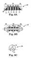
- FIG. 8Ais a perspective view of one embodiment of an abrading head of the present invention.
- FIG. 8Bis a side view of one embodiment of an abrading head of the present invention.
- FIG. 8Cis a bottom view of one embodiment of an abrading head of the present invention.
- FIG. 8Dis a front view of one embodiment of an abrading head of the present invention.
- FIG. 9Ais a side view of one embodiment of an abrading head of the present invention.
- FIG. 9Bis a bottom view of one embodiment of an abrading head of the present invention.
- FIG. 9Cis a front view of one embodiment of an abrading head of the present invention.
- FIG. 10Ais a side view of one embodiment of an abrading head of the present invention.
- FIG. 10Bis a bottom view of one embodiment of an abrading head of the present invention.
- FIG. 10Cis a front view of one embodiment of an abrading head of the present invention.
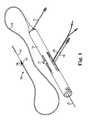
- FIG. 1illustrates one embodiment of a rotational atherectomy device according to the present invention.
- the deviceincludes a handle portion 10 , an elongated, flexible drive shaft 20 having an eccentric enlarged abrading head 28 , the abrading head having at least one groove 29 , and an elongated catheter 13 extending distally from the handle portion 10 .
- the drive shaft 20is constructed from helically coiled wire as is known in the art and the abrading head 28 is fixedly attached thereto.
- Grooves 29are illustrated along the tissue-removing surface of abrading head 28 . In the illustrated embodiment grooves 29 are axial, though other arrangements of the grooves 29 are within the scope of the present invention and are discussed further herein.
- the catheter 13has a lumen in which most of the length of the drive shaft 20 is disposed, except for the enlarged abrading head 28 and a short section distal to the enlarged abrading head 28 .
- the drive shaft 20also contains an inner lumen, permitting the drive shaft 20 to be advanced and rotated over a guide wire 15 .
- a fluid supply line 17may be provided for introducing a cooling and lubricating solution (typically saline or another biocompatible fluid) into the catheter 13 .
- the handle 10desirably contains a turbine (or similar rotational drive mechanism) for rotating the drive shaft 20 at high speeds.
- the handle 10typically may be connected to a power source, such as compressed air delivered through a tube 16 .
- a pair of fiber optic cables 25alternatively a single fiber optic cable may be used, may also be provided for monitoring the speed of rotation of the turbine and drive shaft 20 (details regarding such handles and associated instrumentation are well know in the industry, and are described, e.g., in U.S. Pat. No. 5,314,407, issued to Auth).
- the handle 10also desirably includes a control knob 11 for advancing and retracting the turbine and drive shaft 20 with respect to the catheter 13 and the body of the handle.
- FIGS. 2 and 3illustrate details of a prior art abrading head comprising an eccentric enlarged diameter abrading section 28 A of a drive shaft 20 A.
- the drive shaft 20 Acomprises one or more helically wound wires 18 which define a guide wire lumen 19 A and a hollow cavity 25 A within the enlarged abrading section 28 A. Except for the guide wire 15 traversing the hollow cavity 25 A, the hollow cavity 25 A is substantially empty.
- the eccentric enlarged diameter abrading section 28 Aincludes, relative to the location of the stenosis, proximal 30 A, intermediate 35 A and distal 40 A portions.
- Wire turns 31 of the proximal portion 30 A of the eccentric enlarged diameter section 28 Apreferably have diameters that progressively increase distally at a generally constant rate, thereby forming generally the shape of a cone.
- Wire turns 41 of the distal portion 40 Apreferably have diameters that progressively decrease distally at a generally constant rate, thereby forming generally the shape of a cone.
- Wire turns 36 of the intermediate portion 35 Aare provided with gradually changing diameters to provide a generally convex outer surface which is shaped to provide a smooth transition between the proximal and distal conical portions of the enlarged eccentric diameter section 28 A of the drive shaft 20 A.
- At least part of the eccentric enlarged diameter abrading section of the drive shaft 28 A(preferably the intermediate portion 35 A) comprises an external surface capable of removing tissue.
- a tissue removing surface 37comprising a coating of an abrasive material 24 A to define a tissue removing segment of the drive shaft 20 A is shown attached directly to the wire turns of the drive shaft 20 A by a suitable binder 26 A.
- FIG. 4illustrates another prior art rotational atherectomy device which, in contrast with the substantially hollow device of FIGS. 2 and 3 , employs a solid asymmetrical abrasive burr 28 B attached to a flexible drive shaft 20 B, rotated over a guide wire 15 such as provided by U.S. Pat. No. 5,681,336 to Clement.
- the eccentric tissue removing burr 28 Bhas a coating of abrasive particles 24 B secured to a portion of its outer surface by a suitable binding material 26 B. This construction has limited utility, however because, as Clement explains at Col.
- the asymmetrical burr 28 Bmust be rotated at “lower speeds than are used with high speed ablation devices, to compensate for heat or imbalance.” That is, given both the size and mass of the solid burr-type construction, it is infeasible to rotate such a burr at the high speeds used during atherectomy procedures, i.e., 20,000-200,000 rpm. Further, the abrasive section of this prior art device is relatively smooth, i.e., grooves are not present. As a result, this prior art device will be less than efficient when dealing with non-calcified and/or soft stenoses.
- the abrading head 28comprises three sections: a cone-shaped distal section 30 , a cylindrical-shaped intermediate section 35 and a cone-shaped proximal section 40 .
- the proximal section 40comprises a proximal outer surface
- the intermediate sectioncomprises an intermediate outer surface
- the distal section 30comprises a distal outer surface, the proximal outer surface having diameters that increase distally, the distal outer surface having diameters that decrease distally, and the intermediate outer surface being cylindrical.
- the intermediate section 35comprises axial grooves 29 .
- the present inventionmay comprise at least one such groove 29 disposed on the outer surface of at least the intermediate section 35 .
- the outer surface of the intermediate section 35further comprises non-grooved sections 31 between each groove 29 .
- the groove(s) 29provide a mechanism and a method for abrading, cutting and/or grinding non-calcified and/or soft tissue by allowing the soft tissue to expand slightly into the groove, rendering this tissue more amenable to abrasion, cutting and/or grinding, i.e., removal by the rapidly rotating abrading head 28 .
- Thisis similar to the use of multiple, parallel blades on a razor; a hair portion left behind by a first blade may “spring up” and be cut by one or more subsequent blades.
- the groove(s) 29provide a pathway allowing abraded, removed material to flow away from the cutting area.
- the number of groove(s) 29may be one or more, i.e., two, three, four, five, six or any suitable number.
- the abrading head 28may further comprise at least one tissue removing surface disposed on the external surface(s) of the intermediate section 35 , the distal section 30 and/or the proximal section 40 to facilitate abrasion of the stenosis during high speed rotation.
- the tissue removing surfacemay comprise a coating of an abrasive material 24 bound to the external surface(s) of the intermediate section 35 , the distal section 30 and/or the proximal section 40 of abrading head 28 .
- the abrasive material 24may be bound to the non-grooved sections 31 located between each groove 29 .
- Alternate embodimentsmay comprise the abrasive material 24 being further bound within the groove(s) 29 .
- the at least one groove 29may be curved in profile or may have a non-curvilinear profile, i.e., a flute shape as is well known to the skilled artisan.
- the abrasive materialmay be any suitable material, such as diamond powder, fused silica, titanium nitride, tungsten carbide, aluminum oxide, boron carbide, or other ceramic materials.
- the abrasive materialis comprised of diamond chips (or diamond dust particles) attached directly to the tissue removing surface(s) by a suitable binder. Such attachment may be achieved using well known techniques, such as conventional electroplating or fusion technologies (see, e.g., U.S. Pat. No. 4,018,576).
- the external tissue removing surfacemay comprise mechanically or chemically roughening the external surface(s) of the intermediate portion 35 , the distal portion 40 and/or the proximal portion 30 to provide a suitable abrasive tissue removing surface.
- the external surfacemay be etched or cut (e.g., with a laser) to provide small but effective abrading surfaces. Other similar techniques may also be utilized to provide a suitable tissue removing surface.
- an at least partially enclosed lumen or slot 23may be provided longitudinally through the enlarged abrading head 28 along the rotational axis 21 of the drive shaft 20 for securing the abrading head 28 to the drive shaft 20 in a manner well known to those skilled in the art.
- an at least partially enclosed lumen or slot 23may be provided longitudinally through the enlarged abrading head 28 along the rotational axis 21 of the drive shaft 20 for securing the abrading head 28 to the drive shaft 20 in a manner well known to those skilled in the art.
- a hollowed section 2is defined by the eccentric abrading head 28 and is provided to lessen the mass of the abrading head 28 to facilitate atraumatic abrasion, and improve predictability of control of the orbital pathway of the abrading head 28 during high speed, i.e., 20,000 to 200,000 rpm, operation, and/or to increase the eccentricity and asymmetry of the abrading head 28 through designed manipulation of the center of mass of the abrading head 28 relative to the rotational axis of the drive shaft as will be discussed further infra, thereby increasing the rotational diameter of the abrading head 28 .
- Alternate embodiments of abrading head 28may not comprise the hollowed section 2 . Hollowed section 2 is not required to achieve eccentricity of the abrading head 28 , comprising a center of mass that is offset from the rotational axis of the drive shaft 20 .
- abrading head 28may be fixedly attached to the drive shaft 20 , wherein the drive shaft comprises one single unit.
- the drive shaft 20may comprise two separate pieces, wherein the enlarged eccentric abrading head 28 is fixedly attached to both drive shaft 20 pieces, with a gap therebetween.
- This two-piece drive shaft construction techniquemay, in combination with hollowed section 2 , allow further manipulation of the placement of the center of mass of the abrading head 28 .
- the size and shape of the hollowed section 2when present, may be modified to optimize the orbital rotational path of the abrading head 28 for particularly desirable rotational speeds.
- At least one eccentric abrading head 28may be attached to the drive shaft 20 .
- One, two, three or more abrading heads 28may be employed, each with differing geometries, profiles, number and placement of groove(s) 29 , abrasive placement and other functional characteristics in order to maximize efficiency and efficacy.
- FIGS. 5 and 6 A- 6 Cillustrates the distal 30 and proximal 40 sections being of symmetrical shape and length as well as equivalent slopes in the distal 30 and proximal sections leading up to the intermediate section 35 .
- Alternate embodimentsmay increase the length of either the proximal portion 30 or the distal portion 40 , to create an asymmetrical profile.
- the symmetry of the abrading head 28 as illustrated in FIGS. 5 and 6 A- 6 Cis preferred, though alternate embodiments may comprise a larger or smaller degree of slope in distal 30 and/or proximal 40 sections.
- the distal 30 and/or proximal 40 sections and/or the intermediate section 35may have a longer or shorter length. Each such combination is within the scope of the present invention.
- the eccentric abrading head 28 of the present inventioncomprises a center of mass 32 that is spaced geometrically and radially away from the longitudinal rotational axis 21 of the drive shaft 20 . Offsetting the center of mass 32 from the drive shaft's axis of rotation 21 provides the enlarged abrading head 28 with an eccentricity that permits it to open an artery to a diameter substantially larger during high-speed rotation than the nominal diameter of the enlarged eccentric abrading head 28 . Preferably the opened diameter is at least twice as large as the nominal resting diameter of the enlarged eccentric abrading head 28 .
- offsetting of the center of mass 32may be enhanced or manipulated by varying the amount of mass and location of mass in the intermediate section 35 by, e.g., including a hollowed section 2 and varying its size, location and shape within the intermediate section 35 .
- the words “eccentric” and “eccentricity”are defined and used herein to refer to either a difference in location between the geometric center of the enlarged abrading head 28 and the rotational axis 21 of the drive shaft 20 , or to a difference in location between the center of mass 32 of the enlarged abrading head 28 and the rotational axis 21 of the drive shaft 20 . Either such difference, at the proper rotational speeds, will enable the eccentric enlarged abrading head 28 to open a stenosis to a diameter substantially greater than the nominal diameter of the eccentric enlarged abrading head 28 .
- the abrading head 28 of the rotational atherectomy device of the inventionmay be constructed of stainless steel, tungsten or similar material.
- the abrading head 28may be a single piece unitary construction or, alternatively, may be an assembly of two or more abrading head components fitted and fixed together to achieve the objects of the present invention.
- FIGS. 7A-7Danother embodiment of the abrading head 28 is illustrated.
- This embodimentillustrates, interalia, the variation of the slope of the distal 30 and proximal 40 sections as compared with the embodiment in FIGS. 6A-6C .
- the embodiment in FIGS. 7A-7Dcomprises a smaller degree of slope in the distal 30 and proximal 30 sections relative to the intermediate section 35 . This smaller degree of slope may contribute to longer distal 30 and proximal 40 sections in comparison with the embodiment of FIGS. 6A-6C .
- axial grooves 29are provided on the intermediate section 35 and not on the distal 30 and/or proximal 40 sections, though addition of groove(s) 29 thereon is within the scope of this invention.
- Abrasive material 24may be bound to the non-grooved sections 31 located between each groove 29 . Alternate embodiments may comprise the abrasive material 24 being further bound within the groove(s) 29 .
- the center of mass 32 of the abrading head 28is offset from the rotational axis 21 of the drive shaft 20 in this embodiment as well as in all others disclosed herein.
- the embodiment illustratedcomprises relatively short distal 40 and proximal 30 sections in combination with a relatively long intermediate section 35 as compared with the embodiments discussed supra. This results in a relatively flattened configuration wherein the center of mass 32 is relatively close to the rotational axis 21 of the drive shaft 20 in comparison with that of the prior-discussed embodiments.
- this exemplary embodimentillustrates several of the variables that may be manipulated to maximize the efficacy of the design.
- the described embodiments supra, and each variation therein,may be further carried forward into still-more alternative embodiments of the abrading head 28 as shown in FIGS. 9A-9C and 10 A- 10 C.
- the groove(s) 29are radial rather than axial with abrasive 24 in the non-grooved regions 31 defined between adjacent grooves 29 .
- an embodiment of the radial grooves 29 R and axial grooves 29 Aintersect to form discrete non-grooved regions 31 with abrasive 24 thereon.
- These discrete non-grooved regions 31may comprise, and are defined by, four edges 31 E to facilitate cutting of stenotic tissue, the sharp edges 31 E formed and defined by the intersection of radial grooves 29 R with the axial grooves 29 A on the intermediate section 35 .
- the distal 30 and/or proximal 40 sectionsmay comprise grooves 29 as well.
- the extent to which a stenosis in an artery can be opened to a diameter larger than the nominal diameter of the enlarged abrading head 28 of the present inventiondepends on several parameters, including the shape of the enlarged abrading head 28 , the mass of the eccentric enlarged abrading head 28 , the distribution of that mass within the abrading head 28 and, therefore, the location of the center of mass 32 within the abrading head 28 with respect to the rotational axis 21 of the drive shaft 20 , and the speed of rotation of the drive shaft 20 and abrading head 28 mounted thereon.
- the speed of rotation of the abrading head 28is a significant factor in determining the centrifugal force with which the tissue removing surface of the enlarged abrading head 28 is pressed against the stenotic tissue, thereby permitting the operator to control the rate of tissue removal.
- Control of the rotational speedalso allows, to some extent, control over the maximum diameter to which the device will open a stenosis.
- Applicantshave also found that the ability to reliably control the force with which the tissue removing surface is pressed against the stenotic tissue not only permits the operator to better control the rate of tissue removal but also provides better control of the size of the particles being removed.
- F cis the centrifugal force
- mis the mass of the enlarged abrading head 28
- ⁇ xis the distance between the center of mass 32 of the enlarged abrading head 28 and the rotational axis 21 of the drive shaft 20
- nis the rotational speed in revolutions per minute (rpm).
- the abrading head 28 of the present inventionmay comprise more mass than typical prior art high speed atherectomy abrading devices.
- a larger orbiti.e., a larger rotational diameter
- using a smaller abrading headwill allow for greater ease of access and less trauma during insertion.
- the eccentric enlarged abrading head 28is repeatedly moved distally and proximally through the stenosis.
- the rotational speed of the devicehe or she is able to control the force with which the tissue removal surface is pressed against the stenotic tissue, thereby being able to better control the speed of the plaque removal as well as the particle size of tissue removed.
- the stenosisis being opened to a diameter larger than the nominal diameter of the enlarged abrading head 28 , the cooling solution and the blood are able to constantly flow around the enlarged abrading head.
- the groove(s) 29 , 29 R and/or 29 Aprovide a channel(s) for fluid flow around the abrading head 28 .
- Such constant flow of blood and cooling solutionconstantly flushes away removed tissue particles, thus providing uniform release of removed particles, once the abrading head 28 has passed through the lesion once.
- the eccentric enlarged abrading head 28may comprise a maximum cross-sectional diameter ranging between about 1.0 mm to about 3.0 mm.
- the eccentric enlarged abrading headmay comprise cross-sectional diameters including, but not limited to: 1.0 mm, 1.25 mm, 1.50 mm, 1.75 mm, 2.0 mm, 2.25 mm, 2.50 mm, 2.75 mm, and 3.0 mm.
- cross-sectional diametersincluding, but not limited to: 1.0 mm, 1.25 mm, 1.50 mm, 1.75 mm, 2.0 mm, 2.25 mm, 2.50 mm, 2.75 mm, and 3.0 mm.
- the eccentricity of the enlarged abrading head 28is dependent on a number of parameters, applicants have found that the following design parameters may be considered regarding the distance between the rotational axis 21 of the drive shaft 20 and the geometric center of a face of a transverse cross-section, taken at a position of maximum cross-sectional diameter of the eccentric enlarged abrading head: for a device having an eccentric enlarged abrading head with a maximum cross-sectional diameter between about 1.0 mm and about 1.5 mm, desirably the geometric center should be spaced away from the rotational axis of the drive shaft by a distance of at least about 0.02 mm, and preferably by a distance of at least about 0.035 mm; for a device having an eccentric enlarged abrading head with a maximum cross-sectional diameter between about 1.5 mm and about 1.75 mm, desirably the geometric center should be spaced away from the rotational axis of the drive shaft by a distance of at least about 0.05 mm, preferably by a
- Design parameterscan also be based on the location of the center of mass.
- the center of massshould be spaced away from the rotational axis of the drive shaft by a distance of at least about 0.013 mm, and preferably by a distance of at least about 0.02 mm;
- the center of massshould be spaced away from the rotational axis of the drive shaft by a distance of at least about 0.03 mm, and preferably by a distance of at least about 0.05 mm;
- the center of massshould be spaced away from the rotational axis of the drive shaft by a distance of at least about 0.03 mm, and preferably by a distance of at least about 0.05 mm;
- the center of massshould be spaced away from the rotational axis of the drive shaft by a distance
- the design parametersare selected so that the enlarged abrading head 28 is sufficiently eccentric that, when rotated over a stationary guide wire 15 (held sufficiently taut so as to preclude any substantial movement of the guide wire) at a rotational speed greater than about 20,000 rpm, at least a portion of its tissue removing surface 37 may rotate through a path (whether or not such path is perfectly regular or circular) having a diameter larger than the maximum nominal diameter of the eccentric enlarged abrading head 28 .
- At least a portion of the abrading head 28may rotate through a path having a diameter at least about 10% larger than the maximum nominal diameter of the eccentric enlarged abrading head 28 , preferably at least about 15% larger than the maximum nominal diameter of the eccentric enlarged abrading head 28 , and most preferably at least about 20% larger than the maximum nominal diameter of the eccentric enlarged abrading head 28 .
- At least a portion of the abrading head 28may rotate through a path having a diameter at least about 20% larger than the maximum nominal diameter of the eccentric enlarged abrading head 28 , preferably at least about 25% larger than the maximum nominal diameter of the eccentric enlarged abrading head 28 , and most preferably at least about 30% larger than the maximum nominal diameter of the eccentric enlarged abrading head 28 .
- At least a portion of the abrading head 28may rotate through a path having a diameter at least about 30% larger than the maximum nominal diameter of the eccentric enlarged abrading head 28 , and preferably at least about 40% larger than the maximum nominal diameter of the eccentric enlarged abrading head 28 .
- design parametersare selected so that the enlarged abrading head 28 is sufficiently eccentric that, when rotated over a stationary guide wire 15 at a speed between about 20,000 rpm and about 200,000 rpm, at least a portion of its abrading head 28 rotates through a path (whether or not such path is perfectly regular or circular) with a maximum diameter that is substantially larger than the maximum nominal diameter of the resting eccentric enlarged abrading head 28 .
- the present inventionis capable of defining a substantially orbital path with a maximum diameter that is incrementally between at least about 50% and about 400% larger than the maximum nominal diameter of the resting eccentric enlarged abrading head 28 .
- such orbital pathcomprises a maximum diameter that is between at least about 200% and about 400% larger than the maximum nominal diameter of the resting eccentric enlarged abrading head 28 .
Landscapes
- Health & Medical Sciences (AREA)
- Surgery (AREA)
- Life Sciences & Earth Sciences (AREA)
- Medical Informatics (AREA)
- Nuclear Medicine, Radiotherapy & Molecular Imaging (AREA)
- Engineering & Computer Science (AREA)
- Biomedical Technology (AREA)
- Heart & Thoracic Surgery (AREA)
- Vascular Medicine (AREA)
- Molecular Biology (AREA)
- Animal Behavior & Ethology (AREA)
- General Health & Medical Sciences (AREA)
- Public Health (AREA)
- Veterinary Medicine (AREA)
- Surgical Instruments (AREA)
- Finish Polishing, Edge Sharpening, And Grinding By Specific Grinding Devices (AREA)
Abstract
Description
Fc=mΔx(πn/30)2
Claims (15)
Priority Applications (7)
| Application Number | Priority Date | Filing Date | Title |
|---|---|---|---|
| US12/464,524US8632557B2 (en) | 2009-05-12 | 2009-05-12 | Rotational atherectomy device and method to improve abrading efficiency |
| JP2012510806AJP5654574B2 (en) | 2009-05-12 | 2010-03-18 | Rotary atherectomy device and system to improve grinding efficiency |
| EP10775219.8AEP2429424B1 (en) | 2009-05-12 | 2010-03-18 | Rotational atherectomy device to improve abrading efficiency |
| PCT/US2010/027829WO2010132147A1 (en) | 2009-05-12 | 2010-03-18 | Rotational atherectomy device and method to improve abrading efficiency |
| AU2010248097AAU2010248097B2 (en) | 2009-05-12 | 2010-03-18 | Rotational atherectomy device and method to improve abrading efficiency |
| CA2755424ACA2755424C (en) | 2009-05-12 | 2010-03-18 | Rotational atherectomy device and method to improve abrading efficiency |
| CN201080020846.1ACN102438535B (en) | 2009-05-12 | 2010-03-18 | Rotational atherectomy device and method for improving grinding efficiency |
Applications Claiming Priority (1)
| Application Number | Priority Date | Filing Date | Title |
|---|---|---|---|
| US12/464,524US8632557B2 (en) | 2009-05-12 | 2009-05-12 | Rotational atherectomy device and method to improve abrading efficiency |
Publications (2)
| Publication Number | Publication Date |
|---|---|
| US20100292720A1 US20100292720A1 (en) | 2010-11-18 |
| US8632557B2true US8632557B2 (en) | 2014-01-21 |
Family
ID=43069131
Family Applications (1)
| Application Number | Title | Priority Date | Filing Date |
|---|---|---|---|
| US12/464,524Active2030-05-13US8632557B2 (en) | 2009-05-12 | 2009-05-12 | Rotational atherectomy device and method to improve abrading efficiency |
Country Status (7)
| Country | Link |
|---|---|
| US (1) | US8632557B2 (en) |
| EP (1) | EP2429424B1 (en) |
| JP (1) | JP5654574B2 (en) |
| CN (1) | CN102438535B (en) |
| AU (1) | AU2010248097B2 (en) |
| CA (1) | CA2755424C (en) |
| WO (1) | WO2010132147A1 (en) |
Cited By (44)
| Publication number | Priority date | Publication date | Assignee | Title |
|---|---|---|---|---|
| US20150005791A1 (en)* | 2013-06-28 | 2015-01-01 | Cardiovascular Systems, Inc. | Atherectomy device having combined open/close drive shaft |
| US20160100941A1 (en)* | 2014-10-13 | 2016-04-14 | Hlt, Inc. | Inversion Delivery Device And Method For A Prosthesis |
| WO2017173370A1 (en)* | 2016-04-01 | 2017-10-05 | Avinger, Inc. | Atherectomy catheter with serrated cutter |
| US9854979B2 (en) | 2013-03-15 | 2018-01-02 | Avinger, Inc. | Chronic total occlusion crossing devices with imaging |
| US9855070B2 (en) | 2014-03-12 | 2018-01-02 | Boston Scientific Limited | Infusion lubricated atherectomy catheter |
| US9949754B2 (en) | 2011-03-28 | 2018-04-24 | Avinger, Inc. | Occlusion-crossing devices |
| US20180206864A1 (en)* | 2017-01-23 | 2018-07-26 | Boston Scientific Scimed, Inc. | Necrosectomy devices and procedures |
| US10052125B2 (en) | 2009-07-01 | 2018-08-21 | Avinger, Inc. | Atherectomy catheter with laterally-displaceable tip |
| US10130386B2 (en) | 2013-07-08 | 2018-11-20 | Avinger, Inc. | Identification of elastic lamina to guide interventional therapy |
| US10244934B2 (en) | 2012-05-14 | 2019-04-02 | Avinger, Inc. | Atherectomy catheter drive assemblies |
| US10271869B2 (en) | 2014-03-01 | 2019-04-30 | Rex Medical, L.P. | Atherectomy device |
| US10307175B2 (en) | 2016-03-26 | 2019-06-04 | Rex Medical, L.P | Atherectomy device |
| US10335173B2 (en) | 2012-09-06 | 2019-07-02 | Avinger, Inc. | Re-entry stylet for catheter |
| US10342491B2 (en) | 2009-05-28 | 2019-07-09 | Avinger, Inc. | Optical coherence tomography for biological imaging |
| US10349974B2 (en) | 2010-07-01 | 2019-07-16 | Avinger, Inc. | Atherectomy catheters with longitudinally displaceable drive shafts |
| US10357277B2 (en) | 2014-07-08 | 2019-07-23 | Avinger, Inc. | High speed chronic total occlusion crossing devices |
| US10363062B2 (en) | 2011-10-17 | 2019-07-30 | Avinger, Inc. | Atherectomy catheters and non-contact actuation mechanism for catheters |
| US10405879B2 (en) | 2014-12-04 | 2019-09-10 | Boston Scientific Scimed, Inc. | Rotatable medical device |
| US10433868B2 (en) | 2014-12-27 | 2019-10-08 | Rex Medical, L.P. | Artherectomy device |
| US10463389B2 (en) | 2014-12-27 | 2019-11-05 | Rex Medical, L.P. | Atherectomy device |
| US10470795B2 (en) | 2014-02-06 | 2019-11-12 | Avinger, Inc. | Atherectomy catheters and occlusion crossing devices |
| US10548478B2 (en) | 2010-07-01 | 2020-02-04 | Avinger, Inc. | Balloon atherectomy catheters with imaging |
| US10568655B2 (en) | 2014-02-06 | 2020-02-25 | Avinger, Inc. | Atherectomy catheters devices having multi-channel bushings |
| US10568520B2 (en) | 2015-07-13 | 2020-02-25 | Avinger, Inc. | Micro-molded anamorphic reflector lens for image guided therapeutic/diagnostic catheters |
| US10729326B2 (en) | 2009-07-01 | 2020-08-04 | Avinger, Inc. | Catheter-based off-axis optical coherence tomography imaging system |
| US10869689B2 (en) | 2017-05-03 | 2020-12-22 | Medtronic Vascular, Inc. | Tissue-removing catheter |
| US10932670B2 (en) | 2013-03-15 | 2021-03-02 | Avinger, Inc. | Optical pressure sensor assembly |
| US10952615B2 (en) | 2012-05-14 | 2021-03-23 | Avinger, Inc. | Optical coherence tomography with graded index fiber for biological imaging |
| US11076773B2 (en) | 2009-04-28 | 2021-08-03 | Avinger, Inc. | Guidewire positioning catheter |
| US11096717B2 (en) | 2013-03-15 | 2021-08-24 | Avinger, Inc. | Tissue collection device for catheter |
| US11135019B2 (en) | 2011-11-11 | 2021-10-05 | Avinger, Inc. | Occlusion-crossing devices, atherectomy devices, and imaging |
| US11134849B2 (en) | 2011-03-28 | 2021-10-05 | Avinger, Inc. | Occlusion-crossing devices, imaging, and atherectomy devices |
| US11224459B2 (en) | 2016-06-30 | 2022-01-18 | Avinger, Inc. | Atherectomy catheter with shapeable distal tip |
| US11253292B2 (en) | 2015-09-13 | 2022-02-22 | Rex Medical, L.P. | Atherectomy device |
| US11278248B2 (en) | 2016-01-25 | 2022-03-22 | Avinger, Inc. | OCT imaging catheter with lag correction |
| US11284916B2 (en) | 2012-09-06 | 2022-03-29 | Avinger, Inc. | Atherectomy catheters and occlusion crossing devices |
| US11344327B2 (en) | 2016-06-03 | 2022-05-31 | Avinger, Inc. | Catheter device with detachable distal end |
| US11357534B2 (en) | 2018-11-16 | 2022-06-14 | Medtronic Vascular, Inc. | Catheter |
| US11382653B2 (en) | 2010-07-01 | 2022-07-12 | Avinger, Inc. | Atherectomy catheter |
| US11406412B2 (en) | 2012-05-14 | 2022-08-09 | Avinger, Inc. | Atherectomy catheters with imaging |
| US11690645B2 (en) | 2017-05-03 | 2023-07-04 | Medtronic Vascular, Inc. | Tissue-removing catheter |
| US11793400B2 (en) | 2019-10-18 | 2023-10-24 | Avinger, Inc. | Occlusion-crossing devices |
| US11819236B2 (en) | 2019-05-17 | 2023-11-21 | Medtronic Vascular, Inc. | Tissue-removing catheter |
| US12167867B2 (en) | 2018-04-19 | 2024-12-17 | Avinger, Inc. | Occlusion-crossing devices |
Families Citing this family (16)
| Publication number | Priority date | Publication date | Assignee | Title |
|---|---|---|---|---|
| DK2744424T3 (en)* | 2011-08-17 | 2018-01-22 | Samuel Shiber | Adaptively rotating catheter to open clogged vessels in the body |
| US20150089785A1 (en)* | 2013-09-30 | 2015-04-02 | Cardiovascular Systems, Inc. | Method of attaching an element to a drive shaft |
| US9468457B2 (en) | 2013-09-30 | 2016-10-18 | Cardiovascular Systems, Inc. | Atherectomy device with eccentric crown |
| CN104750638B (en)* | 2013-12-30 | 2018-10-19 | 北京信息科技大学 | A kind of interface adapter and the method for cutting out compatible with Wishbone |
| US10405878B2 (en) | 2014-07-25 | 2019-09-10 | Boston Scientific Scimed, Inc. | Rotatable medical device |
| EP3240493B1 (en) | 2014-12-30 | 2020-02-26 | Bard Peripheral Vascular | Abrasive elements for rotational atherectormy systems |
| US10639062B2 (en)* | 2016-04-06 | 2020-05-05 | Cardio Flow, Inc. | Atherectomy devices and methods |
| CN109862838B (en)* | 2016-10-18 | 2023-01-31 | 密歇根大学董事会 | Two-stage technique and catheter temperature control system for restoring arterial patency with atherectomy |
| CN109483417B (en)* | 2018-12-28 | 2023-12-26 | 西安增材制造国家研究院有限公司 | Metal-based micro-lubrication grinding wheel and manufacturing method thereof |
| JP7326419B2 (en)* | 2020-03-23 | 2023-08-15 | バード・ペリフェラル・バスキュラー・インコーポレーテッド | Abrasive elements for rotary atherectomy systems |
| JP7042861B2 (en)* | 2020-03-23 | 2022-03-28 | バード・ペリフェラル・バスキュラー・インコーポレーテッド | Abrasive elements for rotary atherectomy system |
| EP4125534B1 (en) | 2020-03-31 | 2025-02-26 | Bard Peripheral Vascular, Inc. | Vascular device insertion system and apparatus |
| US11523841B2 (en)* | 2020-09-03 | 2022-12-13 | Cardiovascular Systems, Inc. | Systems, methods and devices for removal of thrombus and/or soft plaque with asymmetric mass distribution within working region of impeller |
| WO2022094228A1 (en)* | 2020-10-30 | 2022-05-05 | Boston Scientific Scimed, Inc. | Atherectomy burrs with blood flow enhancements |
| CN116367788A (en)* | 2020-11-02 | 2023-06-30 | 巴德外周血管股份有限公司 | Orbital atherectomy system with abrasive elements |
| CN114368161B (en)* | 2021-11-25 | 2024-03-26 | 广州博鑫医疗技术有限公司 | Manufacturing method of eccentric rotary grinding assembly and eccentric rotary grinding assembly |
Citations (26)
| Publication number | Priority date | Publication date | Assignee | Title |
|---|---|---|---|---|
| US3937222A (en) | 1973-11-09 | 1976-02-10 | Surgical Design Corporation | Surgical instrument employing cutter means |
| US4445509A (en) | 1982-02-04 | 1984-05-01 | Auth David C | Method and apparatus for removal of enclosed abnormal deposits |
| US4990134A (en) | 1986-01-06 | 1991-02-05 | Heart Technology, Inc. | Transluminal microdissection device |
| US5308354A (en) | 1991-07-15 | 1994-05-03 | Zacca Nadim M | Atherectomy and angioplasty method and apparatus |
| US5312427A (en) | 1992-10-16 | 1994-05-17 | Shturman Cardiology Systems, Inc. | Device and method for directional rotational atherectomy |
| US5356418A (en) | 1992-10-28 | 1994-10-18 | Shturman Cardiology Systems, Inc. | Apparatus and method for rotational atherectomy |
| US5632755A (en) | 1992-11-09 | 1997-05-27 | Endo Vascular Intruments, Inc. | Intra-artery obstruction clearing apparatus and methods |
| US5665098A (en) | 1992-11-09 | 1997-09-09 | Endovascular Instruments, Inc. | Unitary removal of plaque |
| US5895397A (en)* | 1990-05-21 | 1999-04-20 | Cardiovascular Imaging Systems, Inc. | Intravascular catheter having combined imaging abrasion head |
| US6132444A (en) | 1997-08-14 | 2000-10-17 | Shturman Cardiology Systems, Inc. | Eccentric drive shaft for atherectomy device and method for manufacture |
| US6270509B1 (en)* | 1997-03-06 | 2001-08-07 | Scimed Life Systems, Inc. | Cancave atherectomy burr with smooth rims |
| US20020007190A1 (en) | 2000-04-05 | 2002-01-17 | Wulfman Edward I. | Intralumenal material removal systems and methods |
| US6494890B1 (en)* | 1997-08-14 | 2002-12-17 | Shturman Cardiology Systems, Inc. | Eccentric rotational atherectomy device |
| US6503261B1 (en) | 2001-01-17 | 2003-01-07 | Scimed Life Systems, Inc. | Bi-directional atherectomy burr |
| US6565588B1 (en) | 2000-04-05 | 2003-05-20 | Pathway Medical Technologies, Inc. | Intralumenal material removal using an expandable cutting device |
| US6572630B1 (en) | 2000-01-31 | 2003-06-03 | Rex Medical, L.P | Atherectomy device |
| US6579299B2 (en) | 2000-01-31 | 2003-06-17 | Rex Medical, L.P. | Atherectomy device |
| US20030125756A1 (en) | 2001-10-19 | 2003-07-03 | Leonid Shturman | Rotational angioplasty device with abrasive crown |
| US20040006358A1 (en) | 2000-04-05 | 2004-01-08 | Pathway Medical Technologies, Inc. | Intralumenal material removal using a cutting device for differential cutting |
| US20050123363A1 (en) | 2003-12-09 | 2005-06-09 | The Boeing Company | Shaper router and method |
| US20050149083A1 (en) | 2004-01-07 | 2005-07-07 | Dmitriy Prudnikov | Terminal guide for rotational atherectomy device and method of using same |
| US20050149084A1 (en)* | 1998-03-05 | 2005-07-07 | Scimed Life Systems, Inc. | Ablation burr |
| US20080103516A1 (en) | 2006-10-04 | 2008-05-01 | Pathway Medical Technologies, Inc. | Interventional catheters having cutter assemblies and differential cutting surfaces for use in such assemblies |
| US20080132929A1 (en) | 2005-07-19 | 2008-06-05 | O'sullivan Denis F | Surgical bur with anti-chatter flute geometry |
| US20080154293A1 (en) | 2006-12-22 | 2008-06-26 | The Spectranetics Corporation | Retractable Separating Systems and Methods |
| US20080306498A1 (en)* | 2007-06-11 | 2008-12-11 | Cardiovascular Systems, Inc. | Eccentric abrading head for high-speed rotational atherectomy devices |
Family Cites Families (8)
| Publication number | Priority date | Publication date | Assignee | Title |
|---|---|---|---|---|
| US8030A (en)* | 1851-04-08 | Celia b | ||
| US2014A (en)* | 1841-03-24 | Machine ecu cutting square-joint dovetails | ||
| US1003A (en)* | 1838-11-09 | Windlass fob weighing anchors | ||
| US5728129A (en) | 1989-02-17 | 1998-03-17 | American Biomed, Inc. | Distal atherectomy catheter |
| CN2238619Y (en)* | 1995-03-29 | 1996-10-30 | 崔连群 | Rotary cutting and rotary polishing catheter driver |
| US5681336A (en) | 1995-09-07 | 1997-10-28 | Boston Scientific Corporation | Therapeutic device for treating vien graft lesions |
| AU2002225680A1 (en)* | 2000-12-18 | 2002-07-01 | Scimed Life Systems, Inc. | Atherectomy burr with micro-engineered cutting surfaces |
| US8348965B2 (en)* | 2007-10-23 | 2013-01-08 | Cardiovascular Systems, Inc. | Rotational atherectomy device with counterweighting |
- 2009
- 2009-05-12USUS12/464,524patent/US8632557B2/enactiveActive
- 2010
- 2010-03-18CACA2755424Apatent/CA2755424C/ennot_activeExpired - Fee Related
- 2010-03-18WOPCT/US2010/027829patent/WO2010132147A1/enactiveApplication Filing
- 2010-03-18CNCN201080020846.1Apatent/CN102438535B/enactiveActive
- 2010-03-18EPEP10775219.8Apatent/EP2429424B1/enactiveActive
- 2010-03-18AUAU2010248097Apatent/AU2010248097B2/ennot_activeCeased
- 2010-03-18JPJP2012510806Apatent/JP5654574B2/enactiveActive
Patent Citations (28)
| Publication number | Priority date | Publication date | Assignee | Title |
|---|---|---|---|---|
| US3937222A (en) | 1973-11-09 | 1976-02-10 | Surgical Design Corporation | Surgical instrument employing cutter means |
| US4445509A (en) | 1982-02-04 | 1984-05-01 | Auth David C | Method and apparatus for removal of enclosed abnormal deposits |
| US4990134A (en) | 1986-01-06 | 1991-02-05 | Heart Technology, Inc. | Transluminal microdissection device |
| US4990134B1 (en) | 1986-01-06 | 1996-11-05 | Heart Techn Inc | Transluminal microdissection device |
| US5895397A (en)* | 1990-05-21 | 1999-04-20 | Cardiovascular Imaging Systems, Inc. | Intravascular catheter having combined imaging abrasion head |
| US5308354A (en) | 1991-07-15 | 1994-05-03 | Zacca Nadim M | Atherectomy and angioplasty method and apparatus |
| US5312427A (en) | 1992-10-16 | 1994-05-17 | Shturman Cardiology Systems, Inc. | Device and method for directional rotational atherectomy |
| US5356418A (en) | 1992-10-28 | 1994-10-18 | Shturman Cardiology Systems, Inc. | Apparatus and method for rotational atherectomy |
| US5632755A (en) | 1992-11-09 | 1997-05-27 | Endo Vascular Intruments, Inc. | Intra-artery obstruction clearing apparatus and methods |
| US5665098A (en) | 1992-11-09 | 1997-09-09 | Endovascular Instruments, Inc. | Unitary removal of plaque |
| US6270509B1 (en)* | 1997-03-06 | 2001-08-07 | Scimed Life Systems, Inc. | Cancave atherectomy burr with smooth rims |
| US6132444A (en) | 1997-08-14 | 2000-10-17 | Shturman Cardiology Systems, Inc. | Eccentric drive shaft for atherectomy device and method for manufacture |
| US6494890B1 (en)* | 1997-08-14 | 2002-12-17 | Shturman Cardiology Systems, Inc. | Eccentric rotational atherectomy device |
| US20050149084A1 (en)* | 1998-03-05 | 2005-07-07 | Scimed Life Systems, Inc. | Ablation burr |
| US6572630B1 (en) | 2000-01-31 | 2003-06-03 | Rex Medical, L.P | Atherectomy device |
| US6579299B2 (en) | 2000-01-31 | 2003-06-17 | Rex Medical, L.P. | Atherectomy device |
| US20020007190A1 (en) | 2000-04-05 | 2002-01-17 | Wulfman Edward I. | Intralumenal material removal systems and methods |
| US6818001B2 (en) | 2000-04-05 | 2004-11-16 | Pathway Medical Technologies, Inc. | Intralumenal material removal systems and methods |
| US6565588B1 (en) | 2000-04-05 | 2003-05-20 | Pathway Medical Technologies, Inc. | Intralumenal material removal using an expandable cutting device |
| US20040006358A1 (en) | 2000-04-05 | 2004-01-08 | Pathway Medical Technologies, Inc. | Intralumenal material removal using a cutting device for differential cutting |
| US6503261B1 (en) | 2001-01-17 | 2003-01-07 | Scimed Life Systems, Inc. | Bi-directional atherectomy burr |
| US20030125756A1 (en) | 2001-10-19 | 2003-07-03 | Leonid Shturman | Rotational angioplasty device with abrasive crown |
| US20050123363A1 (en) | 2003-12-09 | 2005-06-09 | The Boeing Company | Shaper router and method |
| US20050149083A1 (en) | 2004-01-07 | 2005-07-07 | Dmitriy Prudnikov | Terminal guide for rotational atherectomy device and method of using same |
| US20080132929A1 (en) | 2005-07-19 | 2008-06-05 | O'sullivan Denis F | Surgical bur with anti-chatter flute geometry |
| US20080103516A1 (en) | 2006-10-04 | 2008-05-01 | Pathway Medical Technologies, Inc. | Interventional catheters having cutter assemblies and differential cutting surfaces for use in such assemblies |
| US20080154293A1 (en) | 2006-12-22 | 2008-06-26 | The Spectranetics Corporation | Retractable Separating Systems and Methods |
| US20080306498A1 (en)* | 2007-06-11 | 2008-12-11 | Cardiovascular Systems, Inc. | Eccentric abrading head for high-speed rotational atherectomy devices |
Non-Patent Citations (1)
| Title |
|---|
| SGS, Solid Carbide Tools, Bur Catalog. Mar. 2007 [retrieved on Apr. 5, 2010]. Retrieved from the internet: >URL: http://www.sgstool.com/catalogs/PDFs/BurCtlg.zip>. |
Cited By (98)
| Publication number | Priority date | Publication date | Assignee | Title |
|---|---|---|---|---|
| US11076773B2 (en) | 2009-04-28 | 2021-08-03 | Avinger, Inc. | Guidewire positioning catheter |
| US11998311B2 (en) | 2009-04-28 | 2024-06-04 | Avinger, Inc. | Guidewire positioning catheter |
| US12178613B2 (en) | 2009-05-28 | 2024-12-31 | Avinger, Inc. | Optical coherence tomography for biological imaging |
| US11284839B2 (en) | 2009-05-28 | 2022-03-29 | Avinger, Inc. | Optical coherence tomography for biological imaging |
| US11839493B2 (en) | 2009-05-28 | 2023-12-12 | Avinger, Inc. | Optical coherence tomography for biological imaging |
| US10342491B2 (en) | 2009-05-28 | 2019-07-09 | Avinger, Inc. | Optical coherence tomography for biological imaging |
| US12053260B2 (en) | 2009-07-01 | 2024-08-06 | Avinger, Inc. | Catheter-based off-axis optical coherence tomography imaging system |
| US10052125B2 (en) | 2009-07-01 | 2018-08-21 | Avinger, Inc. | Atherectomy catheter with laterally-displaceable tip |
| US11717314B2 (en) | 2009-07-01 | 2023-08-08 | Avinger, Inc. | Atherectomy catheter with laterally-displaceable tip |
| US10729326B2 (en) | 2009-07-01 | 2020-08-04 | Avinger, Inc. | Catheter-based off-axis optical coherence tomography imaging system |
| US12089868B2 (en) | 2009-07-01 | 2024-09-17 | Avinger, Inc. | Methods of using atherectomy catheter with deflectable distal tip |
| US11382653B2 (en) | 2010-07-01 | 2022-07-12 | Avinger, Inc. | Atherectomy catheter |
| US10548478B2 (en) | 2010-07-01 | 2020-02-04 | Avinger, Inc. | Balloon atherectomy catheters with imaging |
| US10349974B2 (en) | 2010-07-01 | 2019-07-16 | Avinger, Inc. | Atherectomy catheters with longitudinally displaceable drive shafts |
| US10952763B2 (en) | 2011-03-28 | 2021-03-23 | Avinger, Inc. | Occlusion-crossing devices |
| US9949754B2 (en) | 2011-03-28 | 2018-04-24 | Avinger, Inc. | Occlusion-crossing devices |
| US12137931B2 (en) | 2011-03-28 | 2024-11-12 | Avinger, Inc. | Occlusion-crossing devices |
| US11903677B2 (en) | 2011-03-28 | 2024-02-20 | Avinger, Inc. | Occlusion-crossing devices, imaging, and atherectomy devices |
| US12257029B2 (en) | 2011-03-28 | 2025-03-25 | Avinger, Inc. | Occlusion-crossing devices, imaging, and atherectomy devices |
| US11134849B2 (en) | 2011-03-28 | 2021-10-05 | Avinger, Inc. | Occlusion-crossing devices, imaging, and atherectomy devices |
| US10363062B2 (en) | 2011-10-17 | 2019-07-30 | Avinger, Inc. | Atherectomy catheters and non-contact actuation mechanism for catheters |
| US12257003B2 (en) | 2011-11-11 | 2025-03-25 | Avinger, Inc. | Occlusion-crossing devices, atherectomy devices, and imaging |
| US11135019B2 (en) | 2011-11-11 | 2021-10-05 | Avinger, Inc. | Occlusion-crossing devices, atherectomy devices, and imaging |
| US11647905B2 (en) | 2012-05-14 | 2023-05-16 | Avinger, Inc. | Optical coherence tomography with graded index fiber for biological imaging |
| US10952615B2 (en) | 2012-05-14 | 2021-03-23 | Avinger, Inc. | Optical coherence tomography with graded index fiber for biological imaging |
| US12171407B2 (en) | 2012-05-14 | 2024-12-24 | Avinger, Inc. | Atherectomy catheter drive assemblies |
| US11406412B2 (en) | 2012-05-14 | 2022-08-09 | Avinger, Inc. | Atherectomy catheters with imaging |
| US11206975B2 (en) | 2012-05-14 | 2021-12-28 | Avinger, Inc. | Atherectomy catheter drive assemblies |
| US10244934B2 (en) | 2012-05-14 | 2019-04-02 | Avinger, Inc. | Atherectomy catheter drive assemblies |
| US10335173B2 (en) | 2012-09-06 | 2019-07-02 | Avinger, Inc. | Re-entry stylet for catheter |
| US11284916B2 (en) | 2012-09-06 | 2022-03-29 | Avinger, Inc. | Atherectomy catheters and occlusion crossing devices |
| US11890076B2 (en) | 2013-03-15 | 2024-02-06 | Avinger, Inc. | Chronic total occlusion crossing devices with imaging |
| US11980386B2 (en) | 2013-03-15 | 2024-05-14 | Avinger, Inc. | Tissue collection device for catheter |
| US11723538B2 (en) | 2013-03-15 | 2023-08-15 | Avinger, Inc. | Optical pressure sensor assembly |
| US10932670B2 (en) | 2013-03-15 | 2021-03-02 | Avinger, Inc. | Optical pressure sensor assembly |
| US10722121B2 (en) | 2013-03-15 | 2020-07-28 | Avinger, Inc. | Chronic total occlusion crossing devices with imaging |
| US11096717B2 (en) | 2013-03-15 | 2021-08-24 | Avinger, Inc. | Tissue collection device for catheter |
| US9854979B2 (en) | 2013-03-15 | 2018-01-02 | Avinger, Inc. | Chronic total occlusion crossing devices with imaging |
| US20150005791A1 (en)* | 2013-06-28 | 2015-01-01 | Cardiovascular Systems, Inc. | Atherectomy device having combined open/close drive shaft |
| US10130386B2 (en) | 2013-07-08 | 2018-11-20 | Avinger, Inc. | Identification of elastic lamina to guide interventional therapy |
| US11944342B2 (en) | 2013-07-08 | 2024-04-02 | Avinger, Inc. | Identification of elastic lamina to guide interventional therapy |
| US10806484B2 (en) | 2013-07-08 | 2020-10-20 | Avinger, Inc. | Identification of elastic lamina to guide interventional therapy |
| US10470795B2 (en) | 2014-02-06 | 2019-11-12 | Avinger, Inc. | Atherectomy catheters and occlusion crossing devices |
| US10568655B2 (en) | 2014-02-06 | 2020-02-25 | Avinger, Inc. | Atherectomy catheters devices having multi-channel bushings |
| US10751083B2 (en) | 2014-03-01 | 2020-08-25 | Rex Medical L.P. | Atherectomy device |
| US10271869B2 (en) | 2014-03-01 | 2019-04-30 | Rex Medical, L.P. | Atherectomy device |
| US12318111B2 (en) | 2014-03-12 | 2025-06-03 | Boston Scientific Medical Device Limited | Infusion lubricated atherectomy catheter |
| US10595893B2 (en) | 2014-03-12 | 2020-03-24 | Boston Scientific Limited | Infusion lubricated atherectomy catheter |
| US9855070B2 (en) | 2014-03-12 | 2018-01-02 | Boston Scientific Limited | Infusion lubricated atherectomy catheter |
| US11497522B2 (en) | 2014-03-12 | 2022-11-15 | Boston Scientific Limited | Infusion lubricated atherectomy catheter |
| US10357277B2 (en) | 2014-07-08 | 2019-07-23 | Avinger, Inc. | High speed chronic total occlusion crossing devices |
| US11931061B2 (en) | 2014-07-08 | 2024-03-19 | Avinger, Inc. | High speed chronic total occlusion crossing devices |
| US11147583B2 (en) | 2014-07-08 | 2021-10-19 | Avinger, Inc. | High speed chronic total occlusion crossing devices |
| US9999504B2 (en)* | 2014-10-13 | 2018-06-19 | Hlt, Inc. | Inversion delivery device and method for a prosthesis |
| US10820995B2 (en) | 2014-10-13 | 2020-11-03 | Hlt, Inc. | Inversion delivery device and method for a prosthesis |
| US20160100941A1 (en)* | 2014-10-13 | 2016-04-14 | Hlt, Inc. | Inversion Delivery Device And Method For A Prosthesis |
| US10405879B2 (en) | 2014-12-04 | 2019-09-10 | Boston Scientific Scimed, Inc. | Rotatable medical device |
| US12185969B2 (en) | 2014-12-04 | 2025-01-07 | Boston Scientific Scimed, Inc. | Rotatable medical device |
| US11596437B2 (en) | 2014-12-04 | 2023-03-07 | Boston Scientific Scimed, Inc. | Rotatable medical device |
| US11426194B2 (en) | 2014-12-27 | 2022-08-30 | Rex Medical L.P. | Atherectomy device |
| US10433868B2 (en) | 2014-12-27 | 2019-10-08 | Rex Medical, L.P. | Artherectomy device |
| US11547434B2 (en) | 2014-12-27 | 2023-01-10 | Rex Medical L.P. | Atherectomy device |
| US10463389B2 (en) | 2014-12-27 | 2019-11-05 | Rex Medical, L.P. | Atherectomy device |
| US11033190B2 (en) | 2015-07-13 | 2021-06-15 | Avinger, Inc. | Micro-molded anamorphic reflector lens for image guided therapeutic/diagnostic catheters |
| US11627881B2 (en) | 2015-07-13 | 2023-04-18 | Avinger, Inc. | Micro-molded anamorphic reflector lens for image guided therapeutic/diagnostic catheters |
| US10568520B2 (en) | 2015-07-13 | 2020-02-25 | Avinger, Inc. | Micro-molded anamorphic reflector lens for image guided therapeutic/diagnostic catheters |
| US11974830B2 (en) | 2015-07-13 | 2024-05-07 | Avinger, Inc. | Micro-molded anamorphic reflector lens for image guided therapeutic/diagnostic catheters |
| US12274822B2 (en) | 2015-09-13 | 2025-04-15 | Rex Medical, L.P. | Atherectomy device |
| US11253292B2 (en) | 2015-09-13 | 2022-02-22 | Rex Medical, L.P. | Atherectomy device |
| US11278248B2 (en) | 2016-01-25 | 2022-03-22 | Avinger, Inc. | OCT imaging catheter with lag correction |
| US11020134B2 (en) | 2016-03-26 | 2021-06-01 | Rex Meddical L.P. | Atherectomy device |
| US11864780B2 (en) | 2016-03-26 | 2024-01-09 | Rex Medical, L.P. | Atherectomy device |
| US10307175B2 (en) | 2016-03-26 | 2019-06-04 | Rex Medical, L.P | Atherectomy device |
| US11957376B2 (en) | 2016-04-01 | 2024-04-16 | Avinger, Inc. | Atherectomy catheter with serrated cutter |
| WO2017173370A1 (en)* | 2016-04-01 | 2017-10-05 | Avinger, Inc. | Atherectomy catheter with serrated cutter |
| CN108882948A (en)* | 2016-04-01 | 2018-11-23 | 阿维格公司 | Atherectomy catheter with serrated cutter |
| US11399863B2 (en) | 2016-04-01 | 2022-08-02 | Avinger, Inc. | Atherectomy catheter with serrated cutter |
| US12279789B2 (en) | 2016-06-03 | 2025-04-22 | Avinger, Inc. | Catheter device with detachable distal end |
| US11344327B2 (en) | 2016-06-03 | 2022-05-31 | Avinger, Inc. | Catheter device with detachable distal end |
| US12161360B2 (en) | 2016-06-30 | 2024-12-10 | Avinger, Inc. | Atherectomy catheter with shaped distal tip |
| US11224459B2 (en) | 2016-06-30 | 2022-01-18 | Avinger, Inc. | Atherectomy catheter with shapeable distal tip |
| US11439417B2 (en)* | 2017-01-23 | 2022-09-13 | Boston Scientific Scimed, Inc. | Necrosectomy devices and procedures |
| US20180206864A1 (en)* | 2017-01-23 | 2018-07-26 | Boston Scientific Scimed, Inc. | Necrosectomy devices and procedures |
| US12357332B2 (en) | 2017-01-23 | 2025-07-15 | Boston Scientific Scimed, Inc. | Necrosectomy devices and procedures |
| US12114887B2 (en) | 2017-05-03 | 2024-10-15 | Medtronic Vascular, Inc. | Tissue-removing catheter with guidewire isolation liner |
| US11690645B2 (en) | 2017-05-03 | 2023-07-04 | Medtronic Vascular, Inc. | Tissue-removing catheter |
| US11871958B2 (en) | 2017-05-03 | 2024-01-16 | Medtronic Vascular, Inc. | Tissue-removing catheter with guidewire isolation liner |
| US11986207B2 (en) | 2017-05-03 | 2024-05-21 | Medtronic Vascular, Inc. | Tissue-removing catheter with guidewire isolation liner |
| US11051842B2 (en) | 2017-05-03 | 2021-07-06 | Medtronic Vascular, Inc. | Tissue-removing catheter with guidewire isolation liner |
| US10987126B2 (en) | 2017-05-03 | 2021-04-27 | Medtronic Vascular, Inc. | Tissue-removing catheter with guidewire isolation liner |
| US10925632B2 (en) | 2017-05-03 | 2021-02-23 | Medtronic Vascular, Inc. | Tissue-removing catheter |
| US10869689B2 (en) | 2017-05-03 | 2020-12-22 | Medtronic Vascular, Inc. | Tissue-removing catheter |
| US11896260B2 (en) | 2017-05-03 | 2024-02-13 | Medtronic Vascular, Inc. | Tissue-removing catheter |
| US12167867B2 (en) | 2018-04-19 | 2024-12-17 | Avinger, Inc. | Occlusion-crossing devices |
| US11357534B2 (en) | 2018-11-16 | 2022-06-14 | Medtronic Vascular, Inc. | Catheter |
| US12161359B2 (en) | 2018-11-16 | 2024-12-10 | Medtronic Vascular, Inc. | Catheter |
| US11819236B2 (en) | 2019-05-17 | 2023-11-21 | Medtronic Vascular, Inc. | Tissue-removing catheter |
| US11793400B2 (en) | 2019-10-18 | 2023-10-24 | Avinger, Inc. | Occlusion-crossing devices |
Also Published As
| Publication number | Publication date |
|---|---|
| EP2429424A1 (en) | 2012-03-21 |
| CA2755424A1 (en) | 2010-11-18 |
| CA2755424C (en) | 2017-07-18 |
| JP2012526606A (en) | 2012-11-01 |
| AU2010248097B2 (en) | 2015-01-22 |
| EP2429424A4 (en) | 2015-03-04 |
| US20100292720A1 (en) | 2010-11-18 |
| CN102438535A (en) | 2012-05-02 |
| WO2010132147A1 (en) | 2010-11-18 |
| AU2010248097A1 (en) | 2011-09-29 |
| JP5654574B2 (en) | 2015-01-14 |
| CN102438535B (en) | 2015-11-25 |
| EP2429424B1 (en) | 2021-12-08 |
Similar Documents
| Publication | Publication Date | Title |
|---|---|---|
| US8632557B2 (en) | Rotational atherectomy device and method to improve abrading efficiency | |
| US8628550B2 (en) | Rotational atherectomy segmented abrading head and method to improve abrading efficiency | |
| US8597313B2 (en) | Eccentric abrading head for high-speed rotational atherectomy devices | |
| US8758377B2 (en) | Eccentric abrading and cutting head for high-speed rotational atherectomy devices | |
| US10052124B2 (en) | Rotational atherectomy device with a system of eccentric abrading heads | |
| US8702735B2 (en) | Eccentric abrading element for high-speed rotational atherectomy devices | |
| HK1151962A (en) | Eccentric abrading and cutting head for high-speed rotational atherectomy devices | |
| HK1151962B (en) | Eccentric abrading and cutting head for high-speed rotational atherectomy devices | |
| HK1164089B (en) | Rotational atherectomy segmented abrading head | |
| HK1148656B (en) | Eccentric abrading element for high-speed rotational atherectomy devices |
Legal Events
| Date | Code | Title | Description |
|---|---|---|---|
| AS | Assignment | Owner name:CARDIOVASCULAR SYSTEMS, INC., MINNESOTA Free format text:ASSIGNMENT OF ASSIGNORS INTEREST;ASSIGNORS:THATCHER, ROBERT J.;KOEHN, PAUL A.;CZYSCON, JOSEPH S.;SIGNING DATES FROM 20090721 TO 20090722;REEL/FRAME:023007/0469 | |
| AS | Assignment | Owner name:PARTNERS FOR GROWTH III, L.P., CALIFORNIA Free format text:SECURITY AGREEMENT;ASSIGNOR:CARDIOVASCULAR SYSTEMS, INC.;REEL/FRAME:024233/0346 Effective date:20100412 | |
| STCF | Information on status: patent grant | Free format text:PATENTED CASE | |
| AS | Assignment | Owner name:CARDIOVASCULAR SYSTEMS, INC., MINNESOTA Free format text:RELEASE BY SECURED PARTY;ASSIGNOR:PARTNERS FOR GROWTH III, L.P.;REEL/FRAME:035678/0128 Effective date:20150427 | |
| FEPP | Fee payment procedure | Free format text:PAT HOLDER NO LONGER CLAIMS SMALL ENTITY STATUS, ENTITY STATUS SET TO UNDISCOUNTED (ORIGINAL EVENT CODE: STOL); ENTITY STATUS OF PATENT OWNER: LARGE ENTITY | |
| FPAY | Fee payment | Year of fee payment:4 | |
| MAFP | Maintenance fee payment | Free format text:PAYMENT OF MAINTENANCE FEE, 8TH YEAR, LARGE ENTITY (ORIGINAL EVENT CODE: M1552); ENTITY STATUS OF PATENT OWNER: LARGE ENTITY Year of fee payment:8 | |
| MAFP | Maintenance fee payment | Free format text:PAYMENT OF MAINTENANCE FEE, 12TH YEAR, LARGE ENTITY (ORIGINAL EVENT CODE: M1553); ENTITY STATUS OF PATENT OWNER: LARGE ENTITY Year of fee payment:12 |