US8632468B2 - Method, system and devices for transjugular intrahepatic portosystemic shunt (TIPS) procedures - Google Patents
Method, system and devices for transjugular intrahepatic portosystemic shunt (TIPS) proceduresDownload PDFInfo
- Publication number
- US8632468B2 US8632468B2US12/392,817US39281709AUS8632468B2US 8632468 B2US8632468 B2US 8632468B2US 39281709 AUS39281709 AUS 39281709AUS 8632468 B2US8632468 B2US 8632468B2
- Authority
- US
- United States
- Prior art keywords
- needle
- puncture needle
- target vessel
- path
- elongated
- Prior art date
- Legal status (The legal status is an assumption and is not a legal conclusion. Google has not performed a legal analysis and makes no representation as to the accuracy of the status listed.)
- Active, expires
Links
Images


Classifications
- A—HUMAN NECESSITIES
- A61—MEDICAL OR VETERINARY SCIENCE; HYGIENE
- A61B—DIAGNOSIS; SURGERY; IDENTIFICATION
- A61B8/00—Diagnosis using ultrasonic, sonic or infrasonic waves
- A61B8/42—Details of probe positioning or probe attachment to the patient
- A61B8/4245—Details of probe positioning or probe attachment to the patient involving determining the position of the probe, e.g. with respect to an external reference frame or to the patient
- A—HUMAN NECESSITIES
- A61—MEDICAL OR VETERINARY SCIENCE; HYGIENE
- A61B—DIAGNOSIS; SURGERY; IDENTIFICATION
- A61B34/00—Computer-aided surgery; Manipulators or robots specially adapted for use in surgery
- A61B34/20—Surgical navigation systems; Devices for tracking or guiding surgical instruments, e.g. for frameless stereotaxis
- A—HUMAN NECESSITIES
- A61—MEDICAL OR VETERINARY SCIENCE; HYGIENE
- A61B—DIAGNOSIS; SURGERY; IDENTIFICATION
- A61B17/00—Surgical instruments, devices or methods
- A61B17/34—Trocars; Puncturing needles
- A61B17/3478—Endoscopic needles, e.g. for infusion
- A—HUMAN NECESSITIES
- A61—MEDICAL OR VETERINARY SCIENCE; HYGIENE
- A61B—DIAGNOSIS; SURGERY; IDENTIFICATION
- A61B17/00—Surgical instruments, devices or methods
- A61B17/00234—Surgical instruments, devices or methods for minimally invasive surgery
- A61B2017/00238—Type of minimally invasive operation
- A61B2017/00243—Type of minimally invasive operation cardiac
- A61B2017/00247—Making holes in the wall of the heart, e.g. laser Myocardial revascularization
- A61B2017/00252—Making holes in the wall of the heart, e.g. laser Myocardial revascularization for by-pass connections, i.e. connections from heart chamber to blood vessel or from blood vessel to blood vessel
- A—HUMAN NECESSITIES
- A61—MEDICAL OR VETERINARY SCIENCE; HYGIENE
- A61B—DIAGNOSIS; SURGERY; IDENTIFICATION
- A61B34/00—Computer-aided surgery; Manipulators or robots specially adapted for use in surgery
- A61B34/10—Computer-aided planning, simulation or modelling of surgical operations
- A61B2034/107—Visualisation of planned trajectories or target regions
- A—HUMAN NECESSITIES
- A61—MEDICAL OR VETERINARY SCIENCE; HYGIENE
- A61B—DIAGNOSIS; SURGERY; IDENTIFICATION
- A61B34/00—Computer-aided surgery; Manipulators or robots specially adapted for use in surgery
- A61B34/20—Surgical navigation systems; Devices for tracking or guiding surgical instruments, e.g. for frameless stereotaxis
- A61B2034/2046—Tracking techniques
- A61B2034/2051—Electromagnetic tracking systems
Definitions
- This inventionrelates to methods, systems and devices for assisting or performing an image-guided transjugular intrahepatic portosystemic shunt (TIPS).
- TIPStransjugular intrahepatic portosystemic shunt
- Transjugular intrahepatic portosystemic shunt (TIPS) proceduresare typically performed to attempt to connect the portal and hepatic veins in the liver in an effort to reduce portal hypertension (i.e. high blood pressure of the portal system of the liver).
- Typical systems and methods for performing TIPS procedureshave shortcomings that do not solve the central problems associated with the procedure.
- the procedureis currently performed by using fluoroscopic images to introduce a long needle called a “Colapinto” needle into the hepatic vein. Once in place, a blind needle stick is made through the hepatic vein wall, through the liver parenchyma toward the portal vein in an attempt to connect the two vessels.
- TIPS systemsuse a puncture needle that is encased in a large hollow guide needle bent at an angle that is appropriate for most TIPS procedures.
- the correct shunt pathis determined by blindly passing the puncture needle in the perceived direction of the target vessel and slowly retracting it while applying negative pressure to a syringe attached to the puncture needle or its hollow cannula and checking to see if blood is returned, indicating a vessel has been struck.
- the procedurecontinues by placing a guide-wire through the puncture needle and confirming its path using fluoroscopy. Once confirmed, a series of dilators and/or a balloon is inflated over the guide-wire and a stent is inserted and expanded to establish a permanent connection, thereby relieving the hypertension condition.
- connection or “shunt”can relieve symptoms and extend life until a suitable donor liver can be arranged or other measures taken as deemed necessary.
- TIPS proceduresalthough minimally invasive, are generally performed in an interventional radiology suite using high doses of fluoroscopy and contrast agents. Furthermore, TIPS procedures and can take an extended period of time, as the procedure is essentially “blind”, and includes minimal possibilities to accurately direct the TIPS needle to the correct location.
- the Colapinto needles used to perform TIPS procedureshave two degrees of freedom, namely a cranial-caudal sliding motion and an axial rotation of the needle about its long axis.
- the puncture needlemay be extended some distance from the end of the Colapinto needle, adding a third degree of freedom.
- TIPS procedurescan be demanding in that the needle trajectories are often incorrect. Frequently, multiple needle passes may be made, which can take an extended amount of time even with experienced physicians. In some cases, it may not be possible to establish the shunt.
- X-ray usee.g., from fluoroscopy devices
- Large doses of contrast agentmay also be delivered to the patient during TIPS procedures, which may interfere with kidney function and have other side effects. Such procedures may also use significant hospital resources and be costly.
- the inventionsolves these and other problems in the art by providing methods, systems and devices for image-guided transjugular intrahepatic portosystemic shunt (TIPS) procedures.
- TIPStransjugular intrahepatic portosystemic shunt
- the inventionrelates to instrumentation and methods for accurately targeting the portal vessel during TIPS procedures using electromagnetic tracking techniques.
- the devices, methods, and systems of the invention for performing transjugular intrahepatic portosystemic shunts (TIPS) proceduresutilize a position sensor to determine the location and trajectory of a puncture needle.
- TIPStransjugular intrahepatic portosystemic shunts
- the inventionincludes a device for performing TIPS procedures that includes a position indicating element that is embedded to or attached to a puncture needle used to establish communication between hepatic and portal veins in a patient's liver.
- the inventionincludes a system for performing image-guided (TIPS) procedures.
- the systemmay include a computer element, a tracking device, an imaging device, a needle assembly, and/or other elements.
- the computer elementmay include one or more processors, a memory device, a power source, a control application, one or more software modules, one or more inputs/outputs, a display device, a user input device, and/or other elements.
- the one or more processorsmay be configured to perform one or more of the features and functions of the invention described herein.
- the memory device or other memory or data storage elements or methodsmay store and/or otherwise provide instructions to the one or more processors.
- the tracking devicemay be operatively connected to the computer element via an input/output or otherwise send and receive data to and from the computer element.
- the tracking devicemay include an electromagnetic tracking device, global positioning system (GPS) enabled tracking device, an ultrasonic tracking device, a fiber-optic tracking device, an optical tracking device, radar tracking device, or other type of tracking device.
- GPSglobal positioning system
- the tracking devicemay be used to obtain data regarding the three-dimensional location, position, coordinates, and/or other information regarding one or more position indicating elements within or around an anatomical region of the patient.
- the needle assemblymay include a Colapinto needle and a puncture needle. While the needle assembly is described herein as including a “Colapinto needle,” a “guide” needle or other elongated hollow instrument having the features ascribed to the “Colapinto” needles referred to herein can be used.
- the distal end of the needle body portion of the Colapinto needlemay be bent such that the tip is at a 45 degree angle relative to the main axis of the needle body portion. In some embodiments, the angle may more or less than 45 degrees.
- the Colapinto needlemay be made from a malleable material such that the angle of the bend may be customizable by a physician or other operator.
- the bendmay be gradual, forming a curve in the distal end/tip of the needle body portion.
- the puncture needlemay be formed using manufacturing techniques and materials so that it is able to exit the distal end of the Colapinto needle.
- the portion of the puncture needle extended outside of the Colapinto needlemay, at least initially, exit along a path proceeding in a direction tangential to the tip of the Colapinto needle.
- the puncture needlemay be formed using a shape memory alloy such as, for example, Nitinol which may be processed so as to be straight in the super-elastic state, such that the puncture needle, as it exits the tip of the Colapinto needle, follows its prescribed path (i.e. tangential to the curve of the Colapinto needle).
- a shape memory alloysuch as, for example, Nitinol which may be processed so as to be straight in the super-elastic state, such that the puncture needle, as it exits the tip of the Colapinto needle, follows its prescribed path (i.e. tangential to the curve of the Colapinto needle).
- the puncture needlemay include one or more position indicating elements that may provide position sensor space data regarding the distal end or tip of the puncture needle.
- the Colapinto needlemay also include one or more position indicating elements that may provide position sensor space data regarding the distal end or tip (or other portion) of the Colapinto needle.
- one or more cannulas, needles, catheters, and/or instruments inserted into the Colapinto needlemay include one or more position indicating elements that may provide position sensor space data regarding the distal end or tip (or other portion) of the cannula, needle, catheter or other instrument.
- the inventionincludes a method for utilizing a system for performing image-guided TIPS procedures that involves determining a digital map of the portal vein or other “target vessel” of the patient.
- the portal vein mapmay be created using images of the patient's anatomy.
- the portal vein mapmay be established using imaging systems and techniques to determine/establish the 3D pathway of a target vessel (e.g., the portal vein). This imaging may include performing a CTA (Computerized tomographic angiography) study, an MRA (Magnetic Resonance Angiogram) study, Rotational fluoroscopic angiographic determination, calibrated biplane angiogram, ultrasound survey of the portal vein, and/or other imaging modalities.
- CTAComputerized tomographic angiography
- MRAMagnetic Resonance Angiogram
- Rotational fluoroscopic angiographic determinationcalibrated biplane angiogram
- calibrated biplane angiogramcalibrated biplane angiogram
- imaging of the anatomy of the patientmay include injecting a contrast agent into the portal system of the patient.
- a scanmay then be performed by an imaging modality to acquire images of the portal system and surrounding anatomy.
- the resultant imagesmay then be examined.
- the geometric pathway of the portal veinis then determined/established and its coordinates recorded in the coordinate system of the images (i.e. “image space”).
- smoothing and other geometric operationsmay be performed to assist with this process.
- this portal vein mapping procedurei.e., imaging and determining pathway of portal vein and/or other operations
- a portal vein mapmay also be established using intra-procedural ultrasound, such that the geometric pathway of the portal vein (or other target vessel) need not be determined using images of the anatomy of the patient acquired prior to insertion of the needle assembly.
- a position sensor/tracking devicesuch as, for example, an electromagnetic tracking device, GPS device, fiber optic tracking device, optical tracking or other tracking device system is set up near the patient.
- the needle assemblymay then be introduced into the anatomy of the patient (for TIPS procedures, the needle assembly will be introduced to the patients vascular system and routed into the hepatic vein).
- the image space information of the previously obtained imagesmay then be registered to position sensor space information regarding the patient.
- the two coordinate systemsare registered using one or more commonly known registration techniques such as, for example, paired point matching, path matching, ultrasound matching, or other registration techniques.
- paired point registrationmay be performed using techniques such as, for example, fiducial based matching in which natural or artificially applied fiducials visible in image space are located in image space, are also identified in position sensor space (e.g., using a probe having one or more position indicating elements associated with the tracking device).
- a transformation matrixmay be calculated to relate image information of the anatomy of the patient to the coordinate system of the tracking device.
- the pathway of the target vesselis determined using a tracked, calibrated ultrasound, then no registration operations are required, as the vessel path is automatically co-registered with the patient and the path is known in position sensor space.
- the Colapinto needleis then introduced into the hepatic vein.
- the initial placement of the Colapinto needle into the hepatic veinmay be established in the conventional manner for TIPS procedures, using one or more of various imaging devices such as, for example, ultrasound to establish initial access to the jugular vein and subsequently the hepatic vein.
- the same catheters and sheaths that are used in the conventional access systemsmay be applied in the same manner up to the point where the Colapinto needle is placed into the hepatic vein of the liver. This may also involve the use of fluoroscopy as the needle is advanced into the vein.
- the tracked puncture needlemay then be introduced into the Colapinto needle (e.g., via a port located at the proximal end of the Colapinto needle) and placed into a position such that the tip of the puncture needle is flush with the tip of the Colapinto needle.
- a cathetermay be introduced into the Colapinto needle along with the puncture needle.
- one or more position indicating elements of the puncture needlemay send position and/or orientation data to the computer element of the system.
- the computer elementmay use this data to display the current location/position of the instruments relative to the anatomy of the patient (including, for example, the previously mapped portal vein and/or other vessels or organs) onto a display device visible to the physician performing the procedure.
- the computer elementmay further calculate potential future paths of one or more instruments (including the puncture needle, a catheter, and/or the Colapinto needle) by projecting ahead where the instruments may go if one or more of the instruments continue in the same direction.
- the displaymay indicate to the physician performing the procedure if the current location and trajectory of the puncture needle will result in a “hit” at a point on the portal vein prior to actually extending the puncture needle and testing for blood return.
- the physician performing the proceduremay determine if the puncture needle will correctly hit the portal vein by simulating what would happen if the physician extended the puncture needle from the Colapinto needle through the wall of the hepatic vein and into the liver parenchyma.
- the path/trajectory of the puncture needlemay be continually observed on the display and potentially adjusted during extension (e.g., by twisting, rotating, or translating the needle or activating an internal steering mechanism, etc.).
- the physicianmay then readjust the housing of the Colapinto needle by, for example, twisting, extending, retracting or otherwise manipulating the housing until it is determined that the puncture needle will cross the portal vein.
- the physicianmay also elect not to extend the needle at all should the physician determine that there is no possibility that a shunt can be correctly established.
- a stentmay then ultimately be placed and deployed to bridge the portal and hepatic veins.
- FIG. 1illustrates an example of an integrated system for image-guided TIPS procedures, according to various embodiments of the invention.
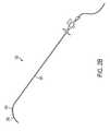
- FIGS. 2A and 2Billustrate examples of Colapinto and puncture needles for use in image guided TIPS procedures, according to various embodiments of the invention.
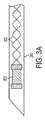
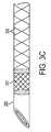
- FIGS. 3A-3Cillustrate examples the distal tip of a puncture needle for use in image-guided TIPS procedures, according to various embodiments of the invention.
- FIG. 4Aillustrates an example of a process for image-guided TIPS procedures, according to various embodiments of the invention.
- FIG. 4Billustrates an example of a process for constructing a 3D path of a target vessel using a tracked, calibrated ultrasound, according to various embodiments of the invention.
- FIG. 5illustrates an example of a display of a portion of a patient's anatomy, according to various embodiments of the invention.
- FIG. 6illustrates an example of a display of a portion of a patient's anatomy including a target vessel relative to a puncture needle, according to various embodiments of the invention.
- FIG. 7illustrates an example of a display of a portion of a patient's anatomy including a target vessel relative to a puncture needle, according to various embodiments of the invention.
- FIG. 8illustrates an example of a display of a portion of a patient's, anatomy including a target vessel relative to a puncture needle, according to various embodiments of the invention.
- FIG. 9illustrates an example of a display of a portion of a patient's anatomy including a target vessel relative to a puncture needle, according to various embodiments of the invention.
- the inventionprovides devices, systems and methods for assisting or performing image-guided transjugular intrahepatic portosystemic shunt (TIPS) procedures.
- TIPSimage-guided transjugular intrahepatic portosystemic shunt
- FIG. 1illustrates a system 100 , which is an example of a system for assisting or performing image-guided TIPS procedures.
- System 100may include a computer element 101 , a tracking device 121 , an imaging device 123 , a needle assembly 125 , and/or other elements.
- Computer element 101may include one or more processors 103 , a memory device 105 , a power source 107 , a control application 109 , one or more software modules 111 a - 111 n , one or more inputs/outputs 113 a - 113 n , a display device 115 , a user input device 117 , and/or other elements.
- the one or more processors 103may be configured to perform one or more of the features and functions of the invention described herein.
- memory device 105 or other memory or data storage elements or methodsmay store data and/or otherwise provide instructions to one or more processors 103 .
- Computer element 101may be or include one or more servers, personal computers, laptop computers, mobile computers, or other computer devices. In some embodiments, computer element 101 may receive, send, store, and/or manipulate data necessary to perform any of the processes, calculations, image formatting, image display, or other operations described herein. In some embodiments, computer element 101 may also perform any processes, calculations, or operations necessary for the function of the devices, elements, instruments, or apparatus described herein.
- control application 109may comprise a computer application which may enable one or more software modules 111 a - 111 n .
- One or more software modules 111 a - 111 nmay enable processor 103 to receive (e.g., via a data reception module), send, and/or manipulate data regarding the anatomy of a patient, one or more objects and/or other data. This data may be stored in memory device 105 or other data storage location.
- one or more software modules 111 a - 111 nmay also enable processor 103 to receive data (e.g., via the data reception module), send, and/or manipulate data regarding the location, position, orientation, and/or coordinates of one or more position indicating elements (e.g., sensor coils or other position indicating elements). This data may be stored in memory device 105 or other data storage location.
- datae.g., via the data reception module
- position indicating elementse.g., sensor coils or other position indicating elements
- one or more software modules 111 a - 111 nmay enable processor 103 to produce, format, and/or reformat one or more images from image space data, position/orientation/location data, and/or other data.
- images produced from image space data, position/orientation/location data, other data, or any combination thereofmay be displayed on display device 115 .
- one or more software modules 111 a - 111 nsuch as, for example, the display module, may enable the generation and display of images of the anatomy of the patient with the position and/or orientation of a tracked instrument (e.g., any instrument having one or more position indicating elements thereupon) superimposed thereon in real time (such that motion of the tracked instrument within the anatomy of the patient is indicated on the superimposed images) for use in an image-guided procedure.
- a tracked instrumente.g., any instrument having one or more position indicating elements thereupon
- one or more software modules 111 a - 111 nsuch as, for example a display module, may enable processor 103 to produce one or more markings, lines, circles, spheres, letters, numbers or other indicators on one or more images of the anatomy of a patient.
- one or more modules 111 a - 111 nmay enable processor 103 to map a target vessel (e.g., a portal vein) or other portion of a patient's anatomy and/or to perform other operations related to a map of the target vessel or portion of the patient's anatomy.
- a target vessele.g., a portal vein
- one or more modules 111 a - 111 nsuch as, for example, display module may generate and display (e.g., on display device 115 ) the position of a puncture needle relative to a target vessel, a projected path of the puncture needle including a path of the puncture needle will follow if the puncture needle is extended past a distal end portion of the guide needle, a point at which the puncture needle will intersect the target vessel if the projected path of the puncture needle intersects the determined path of the target vessel, and an indicator of the closest approach from the puncture needle to the target vessel if the projected path of the puncture needle does not intersect the determined path of the target vessel.
- display device 115may include a computer monitor or other visual display device such as, for example, an LCD display, plasma screen display, cathode ray tube display, or other display device.
- input device 117may include one or more of a mouse, a stylus, a keyboard, a touchscreen interface (which may be associated with or integrated with display device 115 ), a voice activated input device (including a microphone and associated voice processing software) and/or other device wherein a user (e.g., a physician performing a TIPS procedure or assistant thereto) can provide input to system 100 or its components.
- tracking device 121may be operatively connected to computer element 101 via an input/output 113 . In some embodiments, tracking device 121 need not be directly operatively connected to computer element 101 , but data may be sent and received between tracking device 121 and computer element 101 .
- Tracking device 121may include an electromagnetic tracking device, global positioning system (GPS) enabled tracking device, an ultrasonic tracking device, a fiber-optic tracking device, an optical tracking device, radar tracking device, or other type of tracking device. Tracking device 121 may be used to obtain data regarding the three-dimensional location, position, coordinates, and/or other information regarding one or more position indicating elements within or around an anatomical region of the patient. Tracking device 121 may provide this data/information to computer element 101 . In some embodiments, the position indicating elements tracked by tracking device 121 , may be placed on or integrated in needle assembly 125 , and/or other elements.
- imaging device 123may include may include x-ray equipment, computerized tomography (CT) equipment, positron emission tomography (PET) equipment, magnetic resonance imaging (MRI) equipment, fluoroscopy equipment, ultrasound equipment, an isocentric fluoroscopic device, a rotational fluoroscopic reconstruction system, a multislice computerized tomography device, an intravascular ultrasound imager, an optical coherence tomography (OCT) device, an optical imaging device, a single photon emission computed tomography device, a magnetic resonance imaging device, or other imaging/scanning equipment.
- CTcomputerized tomography
- PETpositron emission tomography
- MRImagnetic resonance imaging
- fluoroscopy equipmentfluoroscopy equipment
- ultrasound equipmentan isocentric fluoroscopic device
- OCToptical coherence tomography
- OCToptical coherence tomography
- optical imaging devicea single photon emission computed tomography device
- magnetic resonance imaging deviceor other imaging/scanning equipment.
- needle assembly 125may include a Colapinto needle and a puncture needle. While needle assembly 125 is described herein as including a “Colapinto needle,” a “guide” needle or other elongated hollow instrument having the features ascribed to the “Colapinto needles” referred to herein can be used.
- FIG. 2Aillustrates a separated needle assembly, which may include a Colapinto needle 201 and a puncture needle 203 .
- Colapinto needle 201may include a standard Colapinto needle having an elongated needle body portion that is hollow along its length (or that otherwise includes a lumen). In some embodiments the Colapinto needle may be referred to as a guide needle.
- the needle body portion of Colapinto needle 201may be, for example, 60 cm long with a 16 gauge (16 G) diameter. Other lengths and/or diameters may be used.
- a portion of the distal end/tip (e.g., the distal 5 cm) of the needle body portion of Colapinto needle 201may be bent.
- the distal end of the needle body portion of Colapinto needle 201may be bent such that the tip is at a 45 degree angle relative to the main axis of the needle body portion. In some embodiments, the angle may more or less than 45 degrees.
- Colapinto needle 201may be made from a malleable material such that the angle of the bend may be customizable by a physician or other operator. In some embodiments, the bend may be gradual, forming a curve in the distal end/tip of the needle body portion. In some embodiments, Colapinto needle 201 may include other elements, such as, for example, elements at the proximal end of the needle body portion (e.g., a hub, a valve, or a port for introducing catheters or other needles into the hollow body of Colapinto needle 201 , and/or other elements).
- elements at the proximal end of the needle body portione.g., a hub, a valve, or a port for introducing catheters or other needles into the hollow body of Colapinto needle 201 , and/or other elements.
- puncture needle 203may also include an elongated needle body portion, sized to slidably fit within the hollow body of Colapinto needle 201 .
- puncture needle 203may be hollow or otherwise have a lumen running the length thereof.
- puncture needle 203may be solid and/or may accommodate a catheter or other lumen bearing device around its outer surface.
- the needle body portion of puncture needle 203may, for example, be 65 cm long and may have an 18 gauge (18 G) diameter.
- FIG. 2Billustrates needle assembly 125 including Colapinto needle 201 assembled with puncture needle 203 , wherein puncture needle 203 is deployed and extends out of Colapinto needle 201 .
- Puncture needle 203may be formed using manufacturing techniques and materials so that as it exits the distal end 205 of Colapinto needle 201 .
- the portion of puncture needle 203 extended outside of Colapinto needle 201may, at least initially, exit along a path proceeding in a direction tangential to tip 205 (or distal end 205 ) of Colapinto needle 201 .
- thismay be accomplished by employing a spring element near the tip of puncture needle 203 that ensures the direction is maintained as tangential to the curve of the Colapinto needle.
- section 207 of puncture needle 203may include or be constructed of a spring element welded proximally to a wire or tube and distally to a sharp tip.
- puncture needle 203may be formed using a shape memory alloy such as, for example, Nitinol which may be processed so as to be straight in the super-elastic state, such that puncture needle 203 , as it exits the tip 205 of Colapinto needle 201 , follows its prescribed path (i.e. tangential to the curve of Colapinto needle 201 ).
- Nitinolhas the advantage of being relatively kink resistant enabling it to be bent to extreme angles with no effect to the integrity of the tube or wire formed from it. Also, when annealed into its super-elastic condition and formed into a straight shape, it will not plastically deform, but will always return to its straight shape, even when tortuously bent.
- puncture needle 203may include one or more position indicating elements that may provide position sensor space data regarding the distal end or tip of puncture needle 203 .
- FIG. 3Aillustrates an enlarged view of a tip portion of puncture needle 203 having a position indicating element 301 , which may be a wire coil or other element that provides position and orientation of the tip portion of puncture needle 203 in position sensor space in concert with a tracking device (e.g., tracking device 121 ).
- Puncture needle 203may also include lead wires 303 extending from position indicating elements 301 up the length of puncture needle 203 .
- Colapinto needle 201may also include one or more position indicating elements that may provide position sensor space data regarding the distal end or tip (or other portion) of Colapinto needle 201 .
- one or more cannulas, needles, catheters, and/or instruments inserted into Colapinto needle 201may include one or more position indicating elements that may provide position sensor space data regarding the distal end or tip (or other portion) of the cannula, needle, catheter or other instrument.
- puncture needle 203wherein puncture needle 203 is solid, a hollow cannula or catheter may be placed over puncture needle 203 so that a conduit for blood flow is provided.
- a solid puncture needle sheathed by a catheteris used to perform a TIPS procedure and thereby bridge the portal vein and the hepatic vein, the solid puncture needle portion may be extracted from the assembly, thereby leaving only the catheter which enables a test for blood return. If blood is returned a successful traversal of the portal vein is confirmed.
- puncture needle 203may be shrouded by a catheter in the same way as a Rösch-Uchida system (see e.g., FIG.
- a position indicating elementmay be wound around the outside of a puncture needle or catheter.
- puncture needle 203may be formed by, for example, welding or shaping a sharp tip onto a hollow tube portion.
- a position indicating elementmay be placed inside the distal portion of the hollow tube portion adjacent to the sharp tip. Any lead wires associated with the position indicating element may run through the interior of the hollow tube portion and may be transitioned to the exterior, if appropriate.
- puncture needle 203may be hollow, therefore enabling blood flow therethrough.
- a position indicating elementmay be wound around the outside of a hollow puncture needle or attached adjacent to the needle.
- FIG. 3Cillustrates puncture needle 203 , wherein the wire comprising position indicating element 307 is wound around the outside of needle 203 , with lead wires 309 also wound around the outside of needle 203 to connection points elsewhere in the system.
- the use of a hollow puncture needleallows a user to dispense with the use of a separate cannula or catheter, as blood (or other fluid) may be drawn directly up the hollow interior of the puncture needle.
- a hollow puncture needlemay be constructed of a hollow spring material such that the lead wires (e.g., lead wires 309 ) of position indicating element 307 may run along the needle's length.
- the puncture needlemay include an exterior wound coil with leadwires either communicated to the inside of the needle at a convenient point or run along the outside of the needle.
- a protective coatingsuch as a heatshrink, pyralene, or other coating may be applied.
- an image guided TIPS proceduremay be assisted/performed on a patient using the systems of the invention such as, for example, system 100 or parts thereof.
- FIG. 4Aillustrates a process 400 , which is an example of a process for assisting/performing an image-guided TIPS procedure.
- an image guided TIPS proceduremay utilize a digital map of the portal vein or other “target vessel” of the patient.
- a portal vein mapmay be created using images of the patient's anatomy.
- process 400may include an operation 401 , wherein one or more images or image scans of the patient are obtained.
- one or more modules 111 a - 111 n of computer element 101may enable computer element 101 to receive the one or more images, images scans and/or other image data.
- the portal vein mapmay be established using imaging systems (e.g., imaging device 123 ) and techniques to determine/establish the 3D pathway of a target vessel (e.g., the portal vein). This imaging may include performing a CTA (Computerized tomographic angiography) study, an MRA (Magnetic Resonance Angiogram) study, Rotational fluoroscopic angiographic determination, calibrated biplane angiogram, ultrasound survey of the portal vein, and/or other imaging modalities.
- CTAComputerized tomographic angiography
- MRAMagnetic Resonance Angiogram
- Rotational fluoroscopic angiographic determinationcalibrated biplane angiogram
- calibrated biplane angiogramcalibrated biplane angiogram
- imaging of the anatomy of the patientmay include injecting a contrast agent into the portal system of the patient.
- a scanmay then be performed by an imaging modality (e.g., imaging device 123 ) to acquire images of the portal system and surrounding anatomy.
- the resultant imagesmay then be examined.
- the geometric pathway of the portal veinis then determined/established and its coordinates recorded in the coordinate system of the images (i.e. “image space”).
- smoothing and other geometric operationsmay be performed to assist with this process.
- this portal vein mapping procedurei.e., imaging and determining pathway of portal vein and/or other operations
- a portal vein mapmay also be established using intra-procedural ultrasound, such that the geometric pathway of the portal vein (or other target vessel) need not be determined using images of the anatomy of the patient acquired prior to insertion of needle assembly 125 .
- FIG. 4Billustrates a process 450 , whereby a tracked and calibrated ultrasound may be used to establish a three dimensional map of the portal vein (or other target vessel).
- a “tracked” ultrasound transducerrefers to an ultrasound transducer fitted with a position indicating element whose position and orientation can be determined in position sensor space by a tracking system (e.g., tracking system 121 ).
- calibrated ultrasound transducerrefers to an ultrasound transducer that is pre-calibrated in a medium simulating human tissue (or otherwise calibrated) so that a location in the 2D image plane of the transducer, when combined with the spatial location and orientation of the transducer's imaging plane (known due to the position indicating elements) provides enough information to determine the spatial location in position sensor space of any point within the scan plane.
- a locationappears at a point u, v (wherein “u,” and “v” correspond to the “x” and “y” location of a point in the coordinate system of the scan plane) in the image plane of the ultrasound and the orientation and location of the ultrasound transducer is known in position sensor space, this information may be combined to determine the location (u, v) in position, sensor space.
- Process 450includes an operation 451 , wherein the tracked and calibrated ultrasound is used to obtain an image of a portion of the patient's anatomy wherein the portal vein (or other target vessel) is located.
- the portal vein's (or other target vessel) location within the imageis identified either manually or using an automated technique.
- Operation 453may include determining the “ultrasound coordinates” (u, v) of the portal vein within the scan plane of the ultrasound transducer.
- the X, Y, Z, position of the identified portion of the portal vein (or other target vessel) within the scan plane of the ultrasoundwill be determined in position sensor space.
- process 450determines whether enough information regarding the portal vein (or other target vessel) has been obtained. If not, process 450 returns to operation 451 to obtain images of additional portions of the portal vein (or other target vessel), which are then visualized and their coordinates in position sensor space are determined. If enough information has been obtained, process 450 proceeds to an operation 459 , wherein this information is used to construct a full 3D position sensor space representation of the path of the portal vein (or other target vessel).
- U.S. Patent Application Publication No. 20070167787U.S. patent application Ser. No. 11/471,629
- the path of the target vesselmay be desirable to segment the path of the target vessel and identify/determine specific points in/on the vessel such as, for example, points forming the centerline of the vessel.
- the pathmay be established as a series of coordinates such that the spatial coordinates of the target vessel are known in image space (e.g., when using preoperative imaging) or position sensor space (e.g., when using intraoperative imaging).
- the pathmay comprise, for example, a series of points smoothed or linked by a piecewise linear or bicubic spline. If the spatial coordinates of the target vessel are initially known in image space, a subsequent registration with position sensor space coordinates establishes the path of the vessel in patient space, where all other measurements take place.
- one or more modules 111 a - 111 n of computer element 101may be used by computer element 101 to assist and/or perform the operations discussed herein regarding creating a map of the portal vein or other portion of the anatomy of the patient such as, for example, determining the geometric pathway of a target vessel in image space, smoothing or other geometric operations, segmenting a target vessel, determining centerline points of a target vessel, smoothing or linking points by a piecewise bicubic spline, and/or other operations associated with creating a map in image space of a target vessel or other portion of the anatomy of a patient.
- a mapping modulemay be used by computer element 101 to assist and/or perform the operations discussed herein regarding creating a map of the portal vein or other portion of the anatomy of the patient such as, for example, determining the geometric pathway of a target vessel in image space, smoothing or other geometric operations, segmenting a target vessel, determining centerline points of a target vessel, smoothing or linking points by a piecewise bicubic spline, and/
- a position sensor/tracking devicesuch as, for example, an electromagnetic tracking device, GPS device, fiber optic tracking device, optical tracking or other tracking device system is set up near the patient.
- Tracking system 121enables a computer system (e.g., computer element 101 ) to determine the location and orientation of position indicating elements (e.g., position indicating elements 301 or 307 ) such as electromagnetic sensing coils, GPS elements, or other positing indicating elements within the volume of the position sensor.
- position indicating elementsmay be attached to one or more elements of the system as described herein (e.g., on or in puncture needle 203 ) and/or on or in the anatomy of the patient.
- Tracking system 121determines the position and orientation of the position indicating elements within its own coordinate system referred to hereinafter interchangeably as “position sensor space” or “patient space”.
- process 400may include an operation 405 , wherein the needle assembly is introduced into the anatomy of the patient (for TIPS procedures, the needle assembly will be introduced to the patient's vascular system and routed into the hepatic vein).
- one or more position indicating elements located within the anatomy of the patientmay be sampled by the tracking system, thereby obtaining position sensor space information regarding needle assembly and/or portions of the anatomy of the patient.
- other methods/instrumentsmay be used to gather position sensor space information regarding the anatomy of the patient.
- the image space information of the imagesare then registered to the position sensor space information.
- the two coordinate systemsare registered using one or more commonly known registration techniques such as, for example, paired point matching, path matching, ultrasound matching, or other registration techniques.
- paired point registrationmay be performed using techniques such as, for example, fiducial based matching in which natural or artificially applied fiducials visible in image space are located in image space, are also identified in position sensor space (e.g., using a probe having one or more position indicating elements associated with tracking system 121 ).
- a transformation matrixmay be calculated to relate image information of the anatomy of the patient to the coordinate system of tracking device 121 .
- Methods of registration that account for liver motionmay be based on intraoperative imaging such as ultrasound or fluoroscopy.
- Other methodsmay include direct liver tracking such as, for example, dynamic referencing of the organ using implanted needles, fiducials, transmitters, and/or other elements that can be used to establish/determine a rigid or non-rigid transformation of the liver from the time of the scan. Additional information regarding dynamic referencing methods can be found in U.S. Patent Application Publication No. 20050182319 (U.S. patent application Ser. No. 11/059,336) entitled “Method and Apparatus for Registration, Verification, and Referencing of Internal Organs.” Liver tracking and motion accounting modeling techniques may be used to track the organ throughout the procedure.
- a tracked, calibrated ultrasound transducermay be used to obtain image space information intra-operatively. In this way, the patient space coordinates of the portal vein (or other portions of a patient's anatomy) may be determined directly. As a tracked and calibrated ultrasound transducer is automatically capable of correlating the images it produces into position sensor space, it may not be necessary to register the image information from the tracked ultrasound to the patient space information.
- the TIPS interventionincludes introducing a Colapinto needle into the hepatic vein (or other vessel or area near the target vessel).
- a Colapinto needleinto the hepatic vein (or other vessel or area near the target vessel).
- needle assembly 125is navigated in an operation 411 , such that Colapinto needle 201 is introduced into the hepatic vein.
- the initial placement of Colapinto needle 201 into the hepatic veinmay be established in the conventional manner for TIPS procedures, using one or more of various imaging devices such as, for example, ultrasound to establish initial access to the jugular vein and subsequently the hepatic vein.
- the same catheters and sheaths that are used in the conventional access systemsmay be applied in the same manner up to the point where Colapinto needle 201 is placed into the hepatic vein of the liver. This may also involve the use of fluoroscopy as the needle is advanced into the vein.
- tracked puncture needle 203is then introduced into Colapinto needle 201 and placed into a position such that the tips of catheter 305 (if used) and puncture needle 203 are flush with the tip of Colapinto needle 201 .
- catheter 305may be introduced into Colapinto needle 201 along with puncture needle 203 .
- various markings on puncture needle 203 and/or spacers placed between a hub of Colapinto needle 201 and a hub of puncture needle 203may be used to establish the proper location for the tip of puncture needle 203 .
- one or more position indicating elementse.g., position indicating element 301 of puncture needle 203 and tracking system 121 of system 100 are operatively connected to or otherwise send data to computer element 101 of system 100 .
- position indicating element 301and/or other position indicating elements associated with system 100 positioned within the active volume of the position sensor
- Computer element 101may use this data to display (e.g., using a display module) the current location/position of the instruments relative to the anatomy of the patient (including, for example, the previously mapped portal vein and/or other vessels or organs) onto a display device (e.g., display device 115 ) visible to the physician performing the procedure.
- display devicee.g., display device 115
- Computer element 101may further calculate (e.g., using a display module) potential future paths of one or more instruments (including puncture needle 203 , catheter 205 , and/or Colapinto needle 201 ) by projecting ahead where the instruments may go if one or more of the instruments continue in the same direction.
- process 400may include an operation 415 , wherein the position and trajectory of puncture needle 203 are generated, projected, and/or displayed on a computer display (e.g., display device 115 ) onto which the registered images of the portal vein have been loaded.
- a computer displaye.g., display device 115
- the displayindicates to the physician performing the procedure if the current location and trajectory of puncture needle 203 (housed within Colapinto needle 201 ) will result in a “hit” at a point on the portal vein prior to actually extending puncture needle 203 and testing for blood return.
- puncture needle 203is tracked at its tip and its location and trajectory are known, the physician performing the procedure may determine if puncture needle 203 will correctly hit the portal vein.
- the physicianmay extend puncture needle 203 from Colapinto needle through the wall of the hepatic vein and into the liver parenchyma until it hits the portal vein.
- the path/trajectory of puncture needle 203may be continually observed on the display and potentially adjusted during extension (e.g., by twisting the needle if beveled or activating an internal steering mechanism).
- operation 417may be performed robotically.
- a stentmay be ultimately placed and deployed to bridge the portal and hepatic veins.
- FIG. 5illustrates a display 500 , which is an example of an ultrasound image (i.e., the image captured by the scan plane of an ultrasound transducer used in conjunction with the system of the invention), wherein the crossing point of the puncture needle with the portal vein is visualized as a circle.
- Line 501 of FIG. 1illustrates a projection of puncture needle 203 onto the scan plane of the ultrasound.
- Circle 503illustrates a point at which the needle is anticipated to cross the scan plane.
- the portion of line 501 above circle 503represents a projection of the path of puncture needle 203 as it passes beyond the scan plane.
- Other representations of puncture needle 203 or other elements of needle assembly 125may also be displayed.
- Typical Colapinto needlesgenerally have only 2 degrees of freedom: a longitudinal motion and a twisting motion. This often makes it difficult to puncture a specific location on a vessel. However, another degree of freedom is actually available, namely, the location of the puncture in the vessel, which is typically somewhat arbitrary. On some scenarios, only a single location of the portal vein may be imaged so the entry point into the portal vein may be constrained. Monitoring multiple points of potential entry of a puncture needle would be advantageous. As such, visualization of and access to a larger portion of a target vessel would be advantageous. In some instances, all potential crossing locations in the portal vein and its tributaries may be monitored by scanning an ultrasound transducer around the anatomy of the patient while imaging the portal vein. However, this scanning of the anatomy may be tedious and difficult to visualize the whole target area. As such, the use of the systems, processes, and features disclosed herein may be used to advantageously enable visualization and access to multiple locations on the portal vein and its branches as valid entry points.
- computer element 101can determine if the current trajectory of puncture needle 203 will come close to or intersect the portal vein's path at any location. The distance between the trajectory and any crossing point may also be determined and displayed to the physician performing the TIPS procedure.
- the path of the portal vein that was determined prior to or during the proceduremay be displayed on display device 115 along with the trajectory of puncture needle 203 .
- the trajectory of puncture needle 203is examined by the physician performing the TIPS procedure to determine if it will cross the portal vein. If a crossing location is found, puncture needle 203 may be extended (e.g. in operation 417 ) until it is calculated to cross from the hepatic vein into the portal vein.
- the physicianmay verify the connection between the veins by examining if blood can be extracted through puncture needle 203 (if hollow) or any hollow cannula or catheter (e.g., catheter 305 ) that is surrounding puncture needle 203 .
- FIG. 6illustrates a display 600 , which is an example of a display of a representation of the portal vein (or other target vessel) and puncture needle 203 .
- Vessel 601 in display 600represents the portal vein.
- Circle 603represents a predefined distance to the portal vein, e.g., a 2 mm approach.
- item 203represents the current location of the tip of puncture needle 203 .
- Dotted line 605represents the trajectory of puncture needle 203 .
- Line 607represents the closest approach to the portal vein.
- the example illustrated in display 600indicates that the current trajectory of puncture needle 203 will not cause the portal vein to be punctured.
- FIG. 7illustrates display 700 , which illustrates multiple depictions of the information depicted in FIG. 6 .
- Display 700illustrates puncture needle 203 , its location and trajectory relative to the representation 601 of the portal vein on several projected views simultaneously.
- the bottom right quadrant of the images displayed in FIG. 7illustrates a live ultrasound view in which progress may be examined. This view is not directly related to the accompanying views of the needle trajectory and vessel path that is shown in the other quadrants of FIG. 7 .
- the circle in the bottom right quadrantillustrates a predicted crossing point of puncture needle 203 's trajectory with the live scan plane of an ultrasound. This is calculated as a result of knowledge of puncture needle 203 's trajectory from its position indicating element (e.g.
- position indicating element 301and the direction of the scan plane that is known in position sensor space due to one or more position indicating elements associated with the ultrasound transducer. Information from these position indicating elements is used with calibration information of the tracked ultrasound and image information to generate and display the location of puncture needle's crossing point with the scan plane.
- the solid linerepresents a projection of puncture needle 203 introduced out of the scan plane, while the dotted line represents a predicted trajectory of puncture needle 203 (again, out of the scan plane) after its crossing point with the scan plane.
- the projected and absolute target distances that are shown in the lower left portion of display 700show the distance from the projected closest approach and current puncture needle tip to the closest approach to the portal vein.
- the projected target distanceshows how close the needle tip will come on its current trajectory (i.e., 14.3 mm in the example of FIG. 7 ).
- the physician performing the TIPS proceduremust then manipulate puncture needle 203 until the projected target distance (i.e., the first number) is zero and then advance with puncture needle 203 until the absolute target distance (i.e., the second number) of the tip to the portal vein is also zero. At that time, the tip of puncture needle 203 and the portal vessel will have crossed.
- FIG. 8illustrates display 800 , which is an example of a comprehensive view of the information displayed in FIGS. 6 and 7 , and which illustrates the scan plane of a tracked and calibrated ultrasound transducer (if used) and what the ultrasound transducer is showing.
- Arch 801 and its associated legs 803indicate the ultrasound transducer's imaging plane or “scan plane.”
- FIG. 9illustrates a display 900 which is an example of an enlarged view of the information displayed in FIG. 8 .
- Display 900illustrates the ultrasound transducer's imaging plane via arch 801 and legs 803 forming a plane and puncture needle 203 .
- Sphere 901indicates a threshold distance from portal vein (e.g., 2.5 mm).
- Circle 903indicates where the ultrasound transducer scan plane will image the portal vein.
- Circle 905illustrates where the current trajectory of puncture needle will intersect with the scan plane.
- the inventionmay include a computer readable medium that includes instructions causing one or more processors (e.g., processor 103 ) to perform some or all of the operations, features, and/or functions of the invention.
- processorse.g., processor 103
- System 100is an exemplary system configuration. Other configurations may exist. For example, one or more computer elements, processors, memory devices, display devices, input devices, tracking devices, imaging devices, needles, catheters, cannulas, and/or other elements may be used. Those having skill in the art will appreciate that the invention described herein may work with various system configurations. Accordingly, more or less of the aforementioned system components may be used and/or combined in various embodiments. In some embodiments, as would be appreciated, the functionalities described herein may be implemented in various combinations of hardware and/or firmware, in addition to, or instead of, software. In some embodiments, the operations of the processes described herein may be performed in an order different from the order described herein. In some embodiments, one or more operations may be omitted or combined. In some embodiments, one or more additional operations may be added.
Landscapes
- Health & Medical Sciences (AREA)
- Life Sciences & Earth Sciences (AREA)
- Surgery (AREA)
- Engineering & Computer Science (AREA)
- Public Health (AREA)
- Animal Behavior & Ethology (AREA)
- Veterinary Medicine (AREA)
- Nuclear Medicine, Radiotherapy & Molecular Imaging (AREA)
- Biomedical Technology (AREA)
- Heart & Thoracic Surgery (AREA)
- Medical Informatics (AREA)
- Molecular Biology (AREA)
- General Health & Medical Sciences (AREA)
- Pathology (AREA)
- Biophysics (AREA)
- Physics & Mathematics (AREA)
- Radiology & Medical Imaging (AREA)
- Robotics (AREA)
- Ultra Sonic Daignosis Equipment (AREA)
- Surgical Instruments (AREA)
- Infusion, Injection, And Reservoir Apparatuses (AREA)
- Magnetic Resonance Imaging Apparatus (AREA)
Abstract
Description
Claims (18)
Priority Applications (5)
| Application Number | Priority Date | Filing Date | Title |
|---|---|---|---|
| US12/392,817US8632468B2 (en) | 2009-02-25 | 2009-02-25 | Method, system and devices for transjugular intrahepatic portosystemic shunt (TIPS) procedures |
| JP2011550675AJP5778585B2 (en) | 2009-02-25 | 2010-01-27 | Method, system and apparatus for transjugular intrahepatic portal generalization shunting |
| CN201080009243.1ACN102395327B (en) | 2009-02-25 | 2010-01-27 | Methods, systems and devices for a transjugular intrahepatic portosystemic shunt (TIPS) procedure |
| EP10703118.9AEP2400912B1 (en) | 2009-02-25 | 2010-01-27 | System and devices for transjugular intrahepatic portosystemic shunt (tips) procedures |
| PCT/IB2010/050354WO2010097719A1 (en) | 2009-02-25 | 2010-01-27 | Method, system and devices for transjugular intrahepatic portosystemic shunt (tips) procedures |
Applications Claiming Priority (1)
| Application Number | Priority Date | Filing Date | Title |
|---|---|---|---|
| US12/392,817US8632468B2 (en) | 2009-02-25 | 2009-02-25 | Method, system and devices for transjugular intrahepatic portosystemic shunt (TIPS) procedures |
Publications (2)
| Publication Number | Publication Date |
|---|---|
| US20100217117A1 US20100217117A1 (en) | 2010-08-26 |
| US8632468B2true US8632468B2 (en) | 2014-01-21 |
Family
ID=42101439
Family Applications (1)
| Application Number | Title | Priority Date | Filing Date |
|---|---|---|---|
| US12/392,817Active2031-04-09US8632468B2 (en) | 2009-02-25 | 2009-02-25 | Method, system and devices for transjugular intrahepatic portosystemic shunt (TIPS) procedures |
Country Status (5)
| Country | Link |
|---|---|
| US (1) | US8632468B2 (en) |
| EP (1) | EP2400912B1 (en) |
| JP (1) | JP5778585B2 (en) |
| CN (1) | CN102395327B (en) |
| WO (1) | WO2010097719A1 (en) |
Cited By (32)
| Publication number | Priority date | Publication date | Assignee | Title |
|---|---|---|---|---|
| WO2016009337A2 (en) | 2014-07-15 | 2016-01-21 | Koninklijke Philips N.V. | Devices and methods for intrahepatic shunts |
| EP3056139A1 (en) | 2015-02-16 | 2016-08-17 | Biosense Webster (Israel) Ltd. | Navigation of an angioplasty guidewire |
| US10255247B2 (en)* | 2014-07-10 | 2019-04-09 | Canon Kabushiki Kaisha | Puncture planning apparatus and puncture system |
| WO2020092064A1 (en) | 2018-10-30 | 2020-05-07 | Corindus, Inc. | System and method for navigating a device through a path to a target location |
| US10667769B2 (en) | 2015-11-10 | 2020-06-02 | Koninklijke Philips N.V. | Method of computed tomography imaging |
| US10806520B2 (en) | 2014-05-23 | 2020-10-20 | Koninklijke Philips N.V. | Imaging apparatus for imaging a first object within a second object |
| US10835327B2 (en) | 2017-09-05 | 2020-11-17 | Acclarent, Inc. | Sensor guided instrument with penetrating feature |
| US11020017B2 (en) | 2015-02-16 | 2021-06-01 | Biosense Webster (Israel) Ltd. | Angioplasty guidewire |
| US11197725B1 (en) | 2020-06-19 | 2021-12-14 | Remedy Robotics, Inc. | Systems and methods for guidance of intraluminal devices within the vasculature |
| US11324548B2 (en) | 2015-08-21 | 2022-05-10 | Baylis Medical Company Inc. | Transvascular electrosurgical devices and systems and methods of using the same |
| US11464485B2 (en) | 2018-12-27 | 2022-10-11 | Avent, Inc. | Transducer-mounted needle assembly with improved electrical connection to power source |
| US11559298B2 (en) | 2018-07-16 | 2023-01-24 | Cilag Gmbh International | Surgical visualization of multiple targets |
| US11589731B2 (en) | 2019-12-30 | 2023-02-28 | Cilag Gmbh International | Visualization systems using structured light |
| US11647980B2 (en) | 2018-12-27 | 2023-05-16 | Avent, Inc. | Methods for needle identification on an ultrasound display screen by determining a meta-frame rate of the data signals |
| US11648060B2 (en) | 2019-12-30 | 2023-05-16 | Cilag Gmbh International | Surgical system for overlaying surgical instrument data onto a virtual three dimensional construct of an organ |
| US11690683B2 (en) | 2021-07-01 | 2023-07-04 | Remedy Robotics, Inc | Vision-based position and orientation determination for endovascular tools |
| US11707332B2 (en) | 2021-07-01 | 2023-07-25 | Remedy Robotics, Inc. | Image space control for endovascular tools |
| US11744667B2 (en) | 2019-12-30 | 2023-09-05 | Cilag Gmbh International | Adaptive visualization by a surgical system |
| US11759283B2 (en) | 2019-12-30 | 2023-09-19 | Cilag Gmbh International | Surgical systems for generating three dimensional constructs of anatomical organs and coupling identified anatomical structures thereto |
| US11776144B2 (en) | 2019-12-30 | 2023-10-03 | Cilag Gmbh International | System and method for determining, adjusting, and managing resection margin about a subject tissue |
| US11832996B2 (en) | 2019-12-30 | 2023-12-05 | Cilag Gmbh International | Analyzing surgical trends by a surgical system |
| US11850104B2 (en) | 2019-12-30 | 2023-12-26 | Cilag Gmbh International | Surgical imaging system |
| US11864729B2 (en) | 2019-12-30 | 2024-01-09 | Cilag Gmbh International | Method of using imaging devices in surgery |
| US12002571B2 (en) | 2019-12-30 | 2024-06-04 | Cilag Gmbh International | Dynamic surgical visualization systems |
| US12053223B2 (en) | 2019-12-30 | 2024-08-06 | Cilag Gmbh International | Adaptive surgical system control according to surgical smoke particulate characteristics |
| US12121307B2 (en) | 2021-07-01 | 2024-10-22 | Remedy Robotics, Inc. | Vision-based position and orientation determination for endovascular tools |
| US12207881B2 (en) | 2019-12-30 | 2025-01-28 | Cilag Gmbh International | Surgical systems correlating visualization data and powered surgical instrument data |
| EP4378412A4 (en)* | 2021-07-30 | 2025-03-19 | Beijing Medis Medical Technology Co., Ltd. | Puncture instrument |
| US12257013B2 (en) | 2019-03-15 | 2025-03-25 | Cilag Gmbh International | Robotic surgical systems with mechanisms for scaling camera magnification according to proximity of surgical tool to tissue |
| WO2025136821A1 (en)* | 2023-12-22 | 2025-06-26 | Mediview Xr, Inc. | System and method for image-guided endoluminal intervention using registered extended reality visualization |
| EP4378405A4 (en)* | 2021-07-30 | 2025-07-30 | Beijing Medis Medical Tech Co Ltd | PUNCTURE SYSTEM |
| US12440266B2 (en) | 2022-04-08 | 2025-10-14 | Boston Scientific Medical Device Limited | Transvascular electrosurgical devices and systems and methods of using the same |
Families Citing this family (52)
| Publication number | Priority date | Publication date | Assignee | Title |
|---|---|---|---|---|
| US20110306025A1 (en)* | 2010-05-13 | 2011-12-15 | Higher Education | Ultrasound Training and Testing System with Multi-Modality Transducer Tracking |
| US20120190970A1 (en) | 2010-11-10 | 2012-07-26 | Gnanasekar Velusamy | Apparatus and method for stabilizing a needle |
| JP6290099B2 (en) | 2012-02-03 | 2018-03-07 | インテュイティブ サージカル オペレーションズ, インコーポレイテッド | Steerable flexible needle with implantable shape sensing function |
| US9439627B2 (en) | 2012-05-22 | 2016-09-13 | Covidien Lp | Planning system and navigation system for an ablation procedure |
| US9439622B2 (en) | 2012-05-22 | 2016-09-13 | Covidien Lp | Surgical navigation system |
| US9439623B2 (en) | 2012-05-22 | 2016-09-13 | Covidien Lp | Surgical planning system and navigation system |
| US8750568B2 (en) | 2012-05-22 | 2014-06-10 | Covidien Lp | System and method for conformal ablation planning |
| US9498182B2 (en) | 2012-05-22 | 2016-11-22 | Covidien Lp | Systems and methods for planning and navigation |
| US9375196B2 (en)* | 2012-07-12 | 2016-06-28 | Covidien Lp | System and method for detecting critical structures using ultrasound |
| WO2014062890A1 (en)* | 2012-10-17 | 2014-04-24 | Worcester Polytechnic Institute | System and method for underactuated control of insertion path for asymmetric tip needles |
| US9592095B2 (en) | 2013-05-16 | 2017-03-14 | Intuitive Surgical Operations, Inc. | Systems and methods for robotic medical system integration with external imaging |
| EP3003194B1 (en)* | 2013-05-31 | 2023-03-08 | Koninklijke Philips N.V. | Assisting apparatus for assisting a user during an interventional procedure |
| CN105324078B (en)* | 2013-06-28 | 2019-04-19 | 皇家飞利浦有限公司 | Scanner independent tracking of interventional instruments |
| WO2015011594A1 (en)* | 2013-07-24 | 2015-01-29 | Koninklijke Philips N.V. | Non-imaging two dimensional array probe and system for automated screening of carotid stenosis |
| CN105451802B (en)* | 2013-08-15 | 2019-04-19 | 直观外科手术操作公司 | Graphical user interface for catheter positioning and insertion |
| WO2015165736A1 (en)* | 2014-04-29 | 2015-11-05 | Koninklijke Philips N.V. | Device for determining a specific position of a catheter |
| CN104013425B (en)* | 2014-06-11 | 2016-10-05 | 深圳开立生物医疗科技股份有限公司 | A kind of ultrasonic device display device and correlation technique |
| EP3169244B1 (en) | 2014-07-16 | 2019-05-15 | Koninklijke Philips N.V. | Intelligent real-time tool and anatomy visualization in 3d imaging workflows for interventional procedures |
| US11723718B2 (en)* | 2015-06-02 | 2023-08-15 | Heartlander Surgical, Inc. | Therapy delivery system that operates on the surface of an anatomical entity |
| EP3413830B1 (en) | 2016-02-12 | 2022-06-15 | Intuitive Surgical Operations, Inc. | Computer program for using registered fluoroscopic images in image-guided surgery |
| US10631838B2 (en) | 2016-05-03 | 2020-04-28 | Covidien Lp | Devices, systems, and methods for locating pressure sensitive critical structures |
| KR102764213B1 (en)* | 2016-06-30 | 2025-02-07 | 인튜어티브 서지컬 오퍼레이션즈 인코포레이티드 | Graphical user interface for displaying guidance information in a plurality of modes during an image-guided procedure |
| EP4620418A2 (en) | 2016-06-30 | 2025-09-24 | Intuitive Surgical Operations, Inc. | Graphical user interface for displaying guidance information during an image-guided procedure |
| EP3328308B1 (en)* | 2016-09-27 | 2019-05-29 | Brainlab AG | Efficient positioning of a mechatronic arm |
| CN106667555B (en)* | 2017-01-17 | 2023-06-16 | 山西医科大学 | Medical sacral nerve puncture positioning and guiding system |
| US11439742B2 (en)* | 2017-02-08 | 2022-09-13 | Veran Medical Technologies, Inc. | Localization needle |
| WO2018195216A1 (en) | 2017-04-18 | 2018-10-25 | Intuitive Surgical Operations, Inc. | Graphical user interface for monitoring an image-guided procedure |
| CN109464228A (en)* | 2017-09-06 | 2019-03-15 | 首都医科大学附属北京佑安医院 | Portohepatic shunt self-expanding stent and implantable device |
| EP3552572A1 (en)* | 2018-04-11 | 2019-10-16 | Koninklijke Philips N.V. | Apparatus and method for assisting puncture planning |
| US12245818B2 (en)* | 2017-12-28 | 2025-03-11 | Koninklijke Philips N.V. | Apparatus and method for assisting puncture planning |
| EP3753507A4 (en)* | 2017-12-29 | 2021-11-17 | Weipeng (Suzhou) Medical Co., Ltd. | Surgical navigation method and system |
| JP7239275B2 (en)* | 2018-04-27 | 2023-03-14 | キヤノンメディカルシステムズ株式会社 | Ultrasound diagnostic device and puncture support program |
| US10470797B1 (en) | 2018-07-17 | 2019-11-12 | SlipStream, LLC | Systems and methods for vascular access |
| CN112566581B (en) | 2018-08-10 | 2024-03-19 | 柯惠有限合伙公司 | System for ablation visualization |
| CN109044504A (en)* | 2018-09-25 | 2018-12-21 | 郑州大学第附属医院 | A kind of novel puncture suit in jugular vein liver |
| EP3632363A1 (en)* | 2018-10-04 | 2020-04-08 | Koninklijke Philips N.V. | Apparatus for designing or configuring a trans-bronchial needle guide |
| KR102747176B1 (en)* | 2018-12-11 | 2024-12-27 | 삼성메디슨 주식회사 | Ultrasound imaging apparatus, method for controlling the same, and computer program product |
| US11617493B2 (en)* | 2018-12-13 | 2023-04-04 | Covidien Lp | Thoracic imaging, distance measuring, surgical awareness, and notification system and method |
| US11801113B2 (en) | 2018-12-13 | 2023-10-31 | Covidien Lp | Thoracic imaging, distance measuring, and notification system and method |
| TWI720398B (en)* | 2019-01-03 | 2021-03-01 | 國立陽明大學 | Intra-needle ultrasound system and its method of use for analysis, tracking, and display of pleura in millimeter scale resolution |
| US11229493B2 (en)* | 2019-01-18 | 2022-01-25 | Nuvasive, Inc. | Motion programming of a robotic device |
| WO2020160129A1 (en)* | 2019-01-31 | 2020-08-06 | Intuitive Surgical Operations, Inc. | Systems and methods for facilitating insertion of a surgical instrument into a surgical space |
| US11766298B2 (en)* | 2019-05-03 | 2023-09-26 | Neil Glossop | Systems, methods, and devices for registering and tracking organs during interventional procedures |
| CN110448359B (en)* | 2019-08-02 | 2021-05-14 | 中国人民解放军总医院 | Operation navigation equipment for improving success rate of transjugular intrahepatic portosystemic shunt and application thereof |
| EP3863706B1 (en) | 2019-12-24 | 2022-08-17 | Angiomed GmbH & Co. Medizintechnik KG | Puncture device to be used in creating a tips shunt |
| US11711596B2 (en) | 2020-01-23 | 2023-07-25 | Covidien Lp | System and methods for determining proximity relative to an anatomical structure |
| US12094061B2 (en) | 2020-03-16 | 2024-09-17 | Covidien Lp | System and methods for updating an anatomical 3D model |
| CN111544113A (en)* | 2020-04-03 | 2020-08-18 | 艾瑞迈迪医疗科技(北京)有限公司 | Target tracking and distance dynamic graphical display method and device in surgical navigation |
| CN113520549B (en)* | 2021-07-30 | 2025-02-11 | 北京迈迪斯医疗技术有限公司 | Puncture instruments |
| CN113456190B (en)* | 2021-07-30 | 2025-02-11 | 北京迈迪斯医疗技术有限公司 | Puncture instruments |
| CN114533214B (en)* | 2021-12-23 | 2024-12-06 | 中国人民解放军第三〇五医院 | A puncture positioning device for cardiology |
| CN117159107B (en)* | 2023-09-25 | 2024-08-02 | 北京富通康影科技有限公司 | A three-source CT system for rapid and low-dose puncture guidance |
Citations (33)
| Publication number | Priority date | Publication date | Assignee | Title |
|---|---|---|---|---|
| US5211165A (en)* | 1991-09-03 | 1993-05-18 | General Electric Company | Tracking system to follow the position and orientation of a device with radiofrequency field gradients |
| US5638819A (en)* | 1995-08-29 | 1997-06-17 | Manwaring; Kim H. | Method and apparatus for guiding an instrument to a target |
| WO1997029682A1 (en) | 1996-02-15 | 1997-08-21 | Biosense Inc. | Locatable biopsy needle |
| US5830222A (en)* | 1995-10-13 | 1998-11-03 | Transvascular, Inc. | Device, system and method for intersititial transvascular intervention |
| US5840025A (en)* | 1993-07-20 | 1998-11-24 | Biosense, Inc. | Apparatus and method for treating cardiac arrhythmias |
| US6064904A (en)* | 1997-11-28 | 2000-05-16 | Picker International, Inc. | Frameless stereotactic CT scanner with virtual needle display for planning image guided interventional procedures |
| US6148095A (en)* | 1997-09-08 | 2000-11-14 | University Of Iowa Research Foundation | Apparatus and method for determining three-dimensional representations of tortuous vessels |
| US6332089B1 (en) | 1996-02-15 | 2001-12-18 | Biosense, Inc. | Medical procedures and apparatus using intrabody probes |
| WO2002062265A2 (en) | 2001-02-06 | 2002-08-15 | Transvacular, Inc. | Methods and apparatus for guided transluminal interventions using vessel wall penetrating catheters and other apparatus |
| US6470207B1 (en)* | 1999-03-23 | 2002-10-22 | Surgical Navigation Technologies, Inc. | Navigational guidance via computer-assisted fluoroscopic imaging |
| US6535756B1 (en)* | 2000-04-07 | 2003-03-18 | Surgical Navigation Technologies, Inc. | Trajectory storage apparatus and method for surgical navigation system |
| US6591129B1 (en) | 1996-02-15 | 2003-07-08 | Biosense, Inc. | Method for treating tissue through injection of a therapeutic agent |
| US6616610B2 (en)* | 2000-11-16 | 2003-09-09 | Ge Medical Systems Kretztechnik Gmbh & Co. Ohg | Method for determination of the direction of introduction and for controlling the introduction path of biopsy needles |
| US20030220557A1 (en) | 2002-03-01 | 2003-11-27 | Kevin Cleary | Image guided liver interventions based on magnetic tracking of internal organ motion |
| US6655386B1 (en)* | 1995-10-13 | 2003-12-02 | Transvascular, Inc. | Transluminal method for bypassing arterial obstructions |
| US6660024B1 (en)* | 1995-10-13 | 2003-12-09 | Transvascular, Inc. | Tissue penetrating catheters having integral imaging transducers and their methods of use |
| US6671538B1 (en)* | 1999-11-26 | 2003-12-30 | Koninklijke Philips Electronics, N.V. | Interface system for use with imaging devices to facilitate visualization of image-guided interventional procedure planning |
| US6782288B2 (en)* | 1998-10-08 | 2004-08-24 | Regents Of The University Of Minnesota | Method and apparatus for positioning a device in a body |
| US6785571B2 (en)* | 2001-03-30 | 2004-08-31 | Neil David Glossop | Device and method for registering a position sensor in an anatomical body |
| US20040267121A1 (en)* | 2003-06-12 | 2004-12-30 | Sarvazyan Armen P. | Device and method for biopsy guidance using a tactile breast imager |
| US20060167416A1 (en)* | 2004-11-23 | 2006-07-27 | Mark Mathis | Steerable device for accessing a target site and methods |
| US20060184011A1 (en)* | 2001-02-06 | 2006-08-17 | Medtronic Vascular, Inc. | In Vivo Localization and Tracking of Tissue Penetrating Catheters Using Magnetic Resonance Imaging |
| US7176936B2 (en)* | 2001-03-27 | 2007-02-13 | Siemens Corporate Research, Inc. | Augmented reality guided instrument positioning with modulated guiding graphics |
| US7319897B2 (en)* | 2002-12-02 | 2008-01-15 | Aesculap Ag & Co. Kg | Localization device display method and apparatus |
| US20080171934A1 (en) | 2007-01-12 | 2008-07-17 | Medtronic Vascular, Inc. | Vessel Position and Configuration Imaging Apparatus and Methods |
| US20090118640A1 (en)* | 2007-11-06 | 2009-05-07 | Steven Dean Miller | Biopsy planning and display apparatus |
| US7660623B2 (en)* | 2003-01-30 | 2010-02-09 | Medtronic Navigation, Inc. | Six degree of freedom alignment display for medical procedures |
| US7662128B2 (en)* | 2002-12-23 | 2010-02-16 | Salcudean Septimiu E | Steerable needle |
| US7809176B2 (en)* | 2005-08-05 | 2010-10-05 | Siemens Aktiengesellschaft | Device and method for automated planning of an access path for a percutaneous, minimally invasive intervention |
| US7811294B2 (en)* | 2004-03-08 | 2010-10-12 | Mediguide Ltd. | Automatic guidewire maneuvering system and method |
| US7822458B2 (en)* | 2005-05-19 | 2010-10-26 | The Johns Hopkins University | Distal bevel-tip needle control device and algorithm |
| US7967742B2 (en)* | 2005-02-14 | 2011-06-28 | Karl Storz Imaging, Inc. | Method for using variable direction of view endoscopy in conjunction with image guided surgical systems |
| US20110270270A1 (en)* | 2010-05-03 | 2011-11-03 | Laurence Vancamberg | Method for determining an insertion trajectory of a tool in a deformable tissular matrix and robotic system executing the method |
Family Cites Families (10)
| Publication number | Priority date | Publication date | Assignee | Title |
|---|---|---|---|---|
| US4151008A (en)* | 1974-11-15 | 1979-04-24 | Spire Corporation | Method involving pulsed light processing of semiconductor devices |
| JP3097525B2 (en) | 1995-11-10 | 2000-10-10 | 株式会社日立製作所 | Data transmission method for performing information filtering |
| AU733341B2 (en)* | 1996-02-02 | 2001-05-10 | Transvascular, Inc. | A device, system and method for interstitial transvascular intervention |
| ES2241037T3 (en)* | 1996-02-15 | 2005-10-16 | Biosense Webster, Inc. | PRECISE DETERMINATION OF THE POSITION OF ENDOSCOPES. |
| US6139777A (en)* | 1998-05-08 | 2000-10-31 | Matsushita Electric Industrial Co., Ltd. | Conductive paste for filling via-hole, double-sided and multilayer printed circuit boards using the same, and method for producing the same |
| GB0026646D0 (en)* | 2000-10-31 | 2000-12-13 | Glaxo Group Ltd | Medicament dispenser |
| US20050182319A1 (en) | 2004-02-17 | 2005-08-18 | Glossop Neil D. | Method and apparatus for registration, verification, and referencing of internal organs |
| US7242573B2 (en)* | 2004-10-19 | 2007-07-10 | E. I. Du Pont De Nemours And Company | Electroconductive paste composition |
| CA2612603C (en) | 2005-06-21 | 2015-05-19 | Traxtal Inc. | Device and method for a trackable ultrasound |
| US7812726B2 (en)* | 2006-08-07 | 2010-10-12 | Pliant Corporation | Tamper event detection films, systems and methods |
- 2009
- 2009-02-25USUS12/392,817patent/US8632468B2/enactiveActive
- 2010
- 2010-01-27JPJP2011550675Apatent/JP5778585B2/ennot_activeExpired - Fee Related
- 2010-01-27CNCN201080009243.1Apatent/CN102395327B/enactiveActive
- 2010-01-27WOPCT/IB2010/050354patent/WO2010097719A1/enactiveApplication Filing
- 2010-01-27EPEP10703118.9Apatent/EP2400912B1/enactiveActive
Patent Citations (34)
| Publication number | Priority date | Publication date | Assignee | Title |
|---|---|---|---|---|
| US5211165A (en)* | 1991-09-03 | 1993-05-18 | General Electric Company | Tracking system to follow the position and orientation of a device with radiofrequency field gradients |
| US5840025A (en)* | 1993-07-20 | 1998-11-24 | Biosense, Inc. | Apparatus and method for treating cardiac arrhythmias |
| US5638819A (en)* | 1995-08-29 | 1997-06-17 | Manwaring; Kim H. | Method and apparatus for guiding an instrument to a target |
| US5830222A (en)* | 1995-10-13 | 1998-11-03 | Transvascular, Inc. | Device, system and method for intersititial transvascular intervention |
| US6660024B1 (en)* | 1995-10-13 | 2003-12-09 | Transvascular, Inc. | Tissue penetrating catheters having integral imaging transducers and their methods of use |
| US6655386B1 (en)* | 1995-10-13 | 2003-12-02 | Transvascular, Inc. | Transluminal method for bypassing arterial obstructions |
| US6591129B1 (en) | 1996-02-15 | 2003-07-08 | Biosense, Inc. | Method for treating tissue through injection of a therapeutic agent |
| WO1997029682A1 (en) | 1996-02-15 | 1997-08-21 | Biosense Inc. | Locatable biopsy needle |
| US6332089B1 (en) | 1996-02-15 | 2001-12-18 | Biosense, Inc. | Medical procedures and apparatus using intrabody probes |
| US6148095A (en)* | 1997-09-08 | 2000-11-14 | University Of Iowa Research Foundation | Apparatus and method for determining three-dimensional representations of tortuous vessels |
| US6064904A (en)* | 1997-11-28 | 2000-05-16 | Picker International, Inc. | Frameless stereotactic CT scanner with virtual needle display for planning image guided interventional procedures |
| US6782288B2 (en)* | 1998-10-08 | 2004-08-24 | Regents Of The University Of Minnesota | Method and apparatus for positioning a device in a body |
| US6470207B1 (en)* | 1999-03-23 | 2002-10-22 | Surgical Navigation Technologies, Inc. | Navigational guidance via computer-assisted fluoroscopic imaging |
| US6671538B1 (en)* | 1999-11-26 | 2003-12-30 | Koninklijke Philips Electronics, N.V. | Interface system for use with imaging devices to facilitate visualization of image-guided interventional procedure planning |
| US6535756B1 (en)* | 2000-04-07 | 2003-03-18 | Surgical Navigation Technologies, Inc. | Trajectory storage apparatus and method for surgical navigation system |
| US6616610B2 (en)* | 2000-11-16 | 2003-09-09 | Ge Medical Systems Kretztechnik Gmbh & Co. Ohg | Method for determination of the direction of introduction and for controlling the introduction path of biopsy needles |
| WO2002062265A2 (en) | 2001-02-06 | 2002-08-15 | Transvacular, Inc. | Methods and apparatus for guided transluminal interventions using vessel wall penetrating catheters and other apparatus |
| US7966057B2 (en)* | 2001-02-06 | 2011-06-21 | Medtronic Vascular, Inc. | Methods and apparatus for guided transluminal interventions using vessel wall penetrating catheters and other apparatus |
| US20060184011A1 (en)* | 2001-02-06 | 2006-08-17 | Medtronic Vascular, Inc. | In Vivo Localization and Tracking of Tissue Penetrating Catheters Using Magnetic Resonance Imaging |
| US7176936B2 (en)* | 2001-03-27 | 2007-02-13 | Siemens Corporate Research, Inc. | Augmented reality guided instrument positioning with modulated guiding graphics |
| US6785571B2 (en)* | 2001-03-30 | 2004-08-31 | Neil David Glossop | Device and method for registering a position sensor in an anatomical body |
| US20030220557A1 (en) | 2002-03-01 | 2003-11-27 | Kevin Cleary | Image guided liver interventions based on magnetic tracking of internal organ motion |
| US7319897B2 (en)* | 2002-12-02 | 2008-01-15 | Aesculap Ag & Co. Kg | Localization device display method and apparatus |
| US7662128B2 (en)* | 2002-12-23 | 2010-02-16 | Salcudean Septimiu E | Steerable needle |
| US7660623B2 (en)* | 2003-01-30 | 2010-02-09 | Medtronic Navigation, Inc. | Six degree of freedom alignment display for medical procedures |
| US20040267121A1 (en)* | 2003-06-12 | 2004-12-30 | Sarvazyan Armen P. | Device and method for biopsy guidance using a tactile breast imager |
| US7811294B2 (en)* | 2004-03-08 | 2010-10-12 | Mediguide Ltd. | Automatic guidewire maneuvering system and method |
| US20060167416A1 (en)* | 2004-11-23 | 2006-07-27 | Mark Mathis | Steerable device for accessing a target site and methods |
| US7967742B2 (en)* | 2005-02-14 | 2011-06-28 | Karl Storz Imaging, Inc. | Method for using variable direction of view endoscopy in conjunction with image guided surgical systems |
| US7822458B2 (en)* | 2005-05-19 | 2010-10-26 | The Johns Hopkins University | Distal bevel-tip needle control device and algorithm |
| US7809176B2 (en)* | 2005-08-05 | 2010-10-05 | Siemens Aktiengesellschaft | Device and method for automated planning of an access path for a percutaneous, minimally invasive intervention |
| US20080171934A1 (en) | 2007-01-12 | 2008-07-17 | Medtronic Vascular, Inc. | Vessel Position and Configuration Imaging Apparatus and Methods |
| US20090118640A1 (en)* | 2007-11-06 | 2009-05-07 | Steven Dean Miller | Biopsy planning and display apparatus |
| US20110270270A1 (en)* | 2010-05-03 | 2011-11-03 | Laurence Vancamberg | Method for determining an insertion trajectory of a tool in a deformable tissular matrix and robotic system executing the method |
Cited By (57)
| Publication number | Priority date | Publication date | Assignee | Title |
|---|---|---|---|---|
| US10806520B2 (en) | 2014-05-23 | 2020-10-20 | Koninklijke Philips N.V. | Imaging apparatus for imaging a first object within a second object |
| US10255247B2 (en)* | 2014-07-10 | 2019-04-09 | Canon Kabushiki Kaisha | Puncture planning apparatus and puncture system |
| US11531726B2 (en)* | 2014-07-10 | 2022-12-20 | Canon Kabushiki Kaisha | Puncture planning apparatus and puncture system |
| WO2016009337A2 (en) | 2014-07-15 | 2016-01-21 | Koninklijke Philips N.V. | Devices and methods for intrahepatic shunts |
| US11369346B2 (en) | 2014-07-15 | 2022-06-28 | Philips Image Guided Therapy Corporation | Devices and methods for intrahepatic shunts |
| EP3056139A1 (en) | 2015-02-16 | 2016-08-17 | Biosense Webster (Israel) Ltd. | Navigation of an angioplasty guidewire |
| US10722139B2 (en) | 2015-02-16 | 2020-07-28 | Biosense Webster (Israel) Ltd. | Navigation of an angioplasty guidewire |
| US11020017B2 (en) | 2015-02-16 | 2021-06-01 | Biosense Webster (Israel) Ltd. | Angioplasty guidewire |
| US11324548B2 (en) | 2015-08-21 | 2022-05-10 | Baylis Medical Company Inc. | Transvascular electrosurgical devices and systems and methods of using the same |
| US10667769B2 (en) | 2015-11-10 | 2020-06-02 | Koninklijke Philips N.V. | Method of computed tomography imaging |
| US10835327B2 (en) | 2017-09-05 | 2020-11-17 | Acclarent, Inc. | Sensor guided instrument with penetrating feature |
| US12181579B2 (en) | 2018-07-16 | 2024-12-31 | Cilag GmbH Intemational | Controlling an emitter assembly pulse sequence |
| US12025703B2 (en) | 2018-07-16 | 2024-07-02 | Cilag Gmbh International | Robotic systems with separate photoacoustic receivers |
| US12092738B2 (en) | 2018-07-16 | 2024-09-17 | Cilag Gmbh International | Surgical visualization system for generating and updating a three-dimensional digital representation from structured light imaging data |
| US11754712B2 (en) | 2018-07-16 | 2023-09-12 | Cilag Gmbh International | Combination emitter and camera assembly |
| US11559298B2 (en) | 2018-07-16 | 2023-01-24 | Cilag Gmbh International | Surgical visualization of multiple targets |
| US11564678B2 (en) | 2018-07-16 | 2023-01-31 | Cilag Gmbh International | Force sensor through structured light deflection |
| EP3873337A4 (en)* | 2018-10-30 | 2022-08-10 | Corindus, Inc. | SYSTEM AND METHOD FOR NAVIGATING A DEVICE THROUGH A PATH TO A TARGET LOCATION |
| US11918423B2 (en) | 2018-10-30 | 2024-03-05 | Corindus, Inc. | System and method for navigating a device through a path to a target location |
| WO2020092064A1 (en) | 2018-10-30 | 2020-05-07 | Corindus, Inc. | System and method for navigating a device through a path to a target location |
| US11464485B2 (en) | 2018-12-27 | 2022-10-11 | Avent, Inc. | Transducer-mounted needle assembly with improved electrical connection to power source |
| US11647980B2 (en) | 2018-12-27 | 2023-05-16 | Avent, Inc. | Methods for needle identification on an ultrasound display screen by determining a meta-frame rate of the data signals |
| US12257013B2 (en) | 2019-03-15 | 2025-03-25 | Cilag Gmbh International | Robotic surgical systems with mechanisms for scaling camera magnification according to proximity of surgical tool to tissue |
| US11759284B2 (en) | 2019-12-30 | 2023-09-19 | Cilag Gmbh International | Surgical systems for generating three dimensional constructs of anatomical organs and coupling identified anatomical structures thereto |
| US11925309B2 (en) | 2019-12-30 | 2024-03-12 | Cilag Gmbh International | Method of using imaging devices in surgery |
| US11744667B2 (en) | 2019-12-30 | 2023-09-05 | Cilag Gmbh International | Adaptive visualization by a surgical system |
| US12207881B2 (en) | 2019-12-30 | 2025-01-28 | Cilag Gmbh International | Surgical systems correlating visualization data and powered surgical instrument data |
| US11759283B2 (en) | 2019-12-30 | 2023-09-19 | Cilag Gmbh International | Surgical systems for generating three dimensional constructs of anatomical organs and coupling identified anatomical structures thereto |
| US11648060B2 (en) | 2019-12-30 | 2023-05-16 | Cilag Gmbh International | Surgical system for overlaying surgical instrument data onto a virtual three dimensional construct of an organ |
| US11776144B2 (en) | 2019-12-30 | 2023-10-03 | Cilag Gmbh International | System and method for determining, adjusting, and managing resection margin about a subject tissue |
| US12096910B2 (en) | 2019-12-30 | 2024-09-24 | Cilag Gmbh International | Surgical hub for use with a surgical system in a surgical procedure |
| US11813120B2 (en) | 2019-12-30 | 2023-11-14 | Cilag Gmbh International | Surgical systems for generating three dimensional constructs of anatomical organs and coupling identified anatomical structures thereto |
| US11832996B2 (en) | 2019-12-30 | 2023-12-05 | Cilag Gmbh International | Analyzing surgical trends by a surgical system |
| US11850104B2 (en) | 2019-12-30 | 2023-12-26 | Cilag Gmbh International | Surgical imaging system |
| US11864729B2 (en) | 2019-12-30 | 2024-01-09 | Cilag Gmbh International | Method of using imaging devices in surgery |
| US11864956B2 (en) | 2019-12-30 | 2024-01-09 | Cilag Gmbh International | Surgical systems for generating three dimensional constructs of anatomical organs and coupling identified anatomical structures thereto |
| US11882993B2 (en) | 2019-12-30 | 2024-01-30 | Cilag Gmbh International | Method of using imaging devices in surgery |
| US11896442B2 (en) | 2019-12-30 | 2024-02-13 | Cilag Gmbh International | Surgical systems for proposing and corroborating organ portion removals |
| US11908146B2 (en) | 2019-12-30 | 2024-02-20 | Cilag Gmbh International | System and method for determining, adjusting, and managing resection margin about a subject tissue |
| US11589731B2 (en) | 2019-12-30 | 2023-02-28 | Cilag Gmbh International | Visualization systems using structured light |
| US12053223B2 (en) | 2019-12-30 | 2024-08-06 | Cilag Gmbh International | Adaptive surgical system control according to surgical smoke particulate characteristics |
| US11925310B2 (en) | 2019-12-30 | 2024-03-12 | Cilag Gmbh International | Method of using imaging devices in surgery |
| US11937770B2 (en) | 2019-12-30 | 2024-03-26 | Cilag Gmbh International | Method of using imaging devices in surgery |
| US12002571B2 (en) | 2019-12-30 | 2024-06-04 | Cilag Gmbh International | Dynamic surgical visualization systems |
| US12193764B2 (en) | 2020-06-19 | 2025-01-14 | Remedy Robotics, Inc. | Systems and methods for guidance of intraluminal devices within the vasculature |
| US11229488B2 (en) | 2020-06-19 | 2022-01-25 | Remedy Robotics, Inc. | Systems and methods for guidance of intraluminal devices within the vasculature |
| US11779406B2 (en) | 2020-06-19 | 2023-10-10 | Remedy Robotics, Inc. | Systems and methods for guidance of intraluminal devices within the vasculature |
| WO2021258113A1 (en)* | 2020-06-19 | 2021-12-23 | Remedy Robotics, Inc. | Systems and methods for guidance of intraluminal devices within the vasculature |
| US11246667B2 (en) | 2020-06-19 | 2022-02-15 | Remedy Robotics, Inc. | Systems and methods for guidance of intraluminal devices within the vasculature |
| US11197725B1 (en) | 2020-06-19 | 2021-12-14 | Remedy Robotics, Inc. | Systems and methods for guidance of intraluminal devices within the vasculature |
| US11707332B2 (en) | 2021-07-01 | 2023-07-25 | Remedy Robotics, Inc. | Image space control for endovascular tools |
| US12121307B2 (en) | 2021-07-01 | 2024-10-22 | Remedy Robotics, Inc. | Vision-based position and orientation determination for endovascular tools |
| US11690683B2 (en) | 2021-07-01 | 2023-07-04 | Remedy Robotics, Inc | Vision-based position and orientation determination for endovascular tools |
| EP4378412A4 (en)* | 2021-07-30 | 2025-03-19 | Beijing Medis Medical Technology Co., Ltd. | Puncture instrument |
| EP4378405A4 (en)* | 2021-07-30 | 2025-07-30 | Beijing Medis Medical Tech Co Ltd | PUNCTURE SYSTEM |
| US12440266B2 (en) | 2022-04-08 | 2025-10-14 | Boston Scientific Medical Device Limited | Transvascular electrosurgical devices and systems and methods of using the same |
| WO2025136821A1 (en)* | 2023-12-22 | 2025-06-26 | Mediview Xr, Inc. | System and method for image-guided endoluminal intervention using registered extended reality visualization |
Also Published As
| Publication number | Publication date |
|---|---|
| EP2400912A1 (en) | 2012-01-04 |
| EP2400912B1 (en) | 2017-05-24 |
| CN102395327A (en) | 2012-03-28 |
| JP2012518453A (en) | 2012-08-16 |
| CN102395327B (en) | 2014-09-24 |
| US20100217117A1 (en) | 2010-08-26 |
| JP5778585B2 (en) | 2015-09-16 |
| WO2010097719A1 (en) | 2010-09-02 |
Similar Documents
| Publication | Publication Date | Title |
|---|---|---|
| US8632468B2 (en) | Method, system and devices for transjugular intrahepatic portosystemic shunt (TIPS) procedures | |
| US10582879B2 (en) | Method and apparatus for registration, verification and referencing of internal organs | |
| US8611983B2 (en) | Method and apparatus for guiding an instrument to a target in the lung | |
| US11864946B2 (en) | Method of employing a medical apparatus with translatable imaging device for real-time confirmation of interception of target tissue | |
| CN102713976B (en) | Navigating an interventional device | |
| CN107205780B (en) | Tracking-based 3D model enhancement | |
| EP3021940B1 (en) | Portal imaging for brachytherapy | |
| US20070232882A1 (en) | System, Methods, and Instrumentation for Image Guided Prostate Treatment | |
| US20140275996A1 (en) | Systems and methods for constructing an image of a body structure | |
| CN115515504A (en) | Automatic control of intraluminal data acquisition and related devices, systems and methods | |
| US11439742B2 (en) | Localization needle | |
| US20090088628A1 (en) | Efficient workflow for afib treatment in the ep lab | |
| US20080306378A1 (en) | Method and system for images registration | |
| US20130261431A1 (en) | Pae treatment for bph | |
| CN104706428A (en) | Interventional therapy needle positioning method and interventional therapy needle |
Legal Events
| Date | Code | Title | Description |
|---|---|---|---|
| AS | Assignment | Owner name:TRAXTAL INC., CANADA Free format text:ASSIGNMENT OF ASSIGNORS INTEREST;ASSIGNORS:GLOSSOP, NEIL DAVID;TANG, THOMAS S.Y.;WOOD, BRADFORD JOHNS;SIGNING DATES FROM 20090707 TO 20090708;REEL/FRAME:022946/0847 | |
| AS | Assignment | Owner name:THE UNITED STATES OF AMERICA, AS REPRESENTED BY TH Free format text:ASSIGNMENT OF ASSIGNORS INTEREST;ASSIGNOR:WOOD, BRADFORD JOHNS;REEL/FRAME:022991/0886 Effective date:20090708 Owner name:TRAXTAL INC., CANADA Free format text:CORRECTIVE ASSIGNMENT TO CORRECT THE ASSIGNORS BY REMOVING THE THIRD ASSIGNOR PREVIOUSLY RECORDED ON REEL 022946 FRAME 0847. ASSIGNOR(S) HEREBY CONFIRMS THE ASSIGNMENT;ASSIGNORS:GLOSSOP, NEIL DAVID;TANG, THOMAS S.Y.;REEL/FRAME:022991/0760 Effective date:20090707 | |
| AS | Assignment | Owner name:PHILIPS ELECTRONICS LTD, CANADA Free format text:MERGER;ASSIGNOR:TRAXTAL INC.;REEL/FRAME:024363/0651 Effective date:20091231 | |
| STCF | Information on status: patent grant | Free format text:PATENTED CASE | |
| FPAY | Fee payment | Year of fee payment:4 | |
| MAFP | Maintenance fee payment | Free format text:PAYMENT OF MAINTENANCE FEE, 8TH YEAR, LARGE ENTITY (ORIGINAL EVENT CODE: M1552); ENTITY STATUS OF PATENT OWNER: LARGE ENTITY Year of fee payment:8 | |
| MAFP | Maintenance fee payment | Free format text:PAYMENT OF MAINTENANCE FEE, 12TH YEAR, LARGE ENTITY (ORIGINAL EVENT CODE: M1553); ENTITY STATUS OF PATENT OWNER: LARGE ENTITY Year of fee payment:12 |