US8632464B2 - System and method for monitoring orthopaedic implant data - Google Patents
System and method for monitoring orthopaedic implant dataDownload PDFInfo
- Publication number
- US8632464B2 US8632464B2US11/530,567US53056706AUS8632464B2US 8632464 B2US8632464 B2US 8632464B2US 53056706 AUS53056706 AUS 53056706AUS 8632464 B2US8632464 B2US 8632464B2
- Authority
- US
- United States
- Prior art keywords
- implant
- sensor data
- data
- transmitter
- controller
- Prior art date
- Legal status (The legal status is an assumption and is not a legal conclusion. Google has not performed a legal analysis and makes no representation as to the accuracy of the status listed.)
- Active, expires
Links
Images


Classifications
- A—HUMAN NECESSITIES
- A61—MEDICAL OR VETERINARY SCIENCE; HYGIENE
- A61B—DIAGNOSIS; SURGERY; IDENTIFICATION
- A61B5/00—Measuring for diagnostic purposes; Identification of persons
- A61B5/0002—Remote monitoring of patients using telemetry, e.g. transmission of vital signals via a communication network
- A61B5/0031—Implanted circuitry
- A—HUMAN NECESSITIES
- A61—MEDICAL OR VETERINARY SCIENCE; HYGIENE
- A61F—FILTERS IMPLANTABLE INTO BLOOD VESSELS; PROSTHESES; DEVICES PROVIDING PATENCY TO, OR PREVENTING COLLAPSING OF, TUBULAR STRUCTURES OF THE BODY, e.g. STENTS; ORTHOPAEDIC, NURSING OR CONTRACEPTIVE DEVICES; FOMENTATION; TREATMENT OR PROTECTION OF EYES OR EARS; BANDAGES, DRESSINGS OR ABSORBENT PADS; FIRST-AID KITS
- A61F2/00—Filters implantable into blood vessels; Prostheses, i.e. artificial substitutes or replacements for parts of the body; Appliances for connecting them with the body; Devices providing patency to, or preventing collapsing of, tubular structures of the body, e.g. stents
- A61F2/02—Prostheses implantable into the body
- A61F2/48—Operating or control means, e.g. from outside the body, control of sphincters
- G—PHYSICS
- G16—INFORMATION AND COMMUNICATION TECHNOLOGY [ICT] SPECIALLY ADAPTED FOR SPECIFIC APPLICATION FIELDS
- G16H—HEALTHCARE INFORMATICS, i.e. INFORMATION AND COMMUNICATION TECHNOLOGY [ICT] SPECIALLY ADAPTED FOR THE HANDLING OR PROCESSING OF MEDICAL OR HEALTHCARE DATA
- G16H20/00—ICT specially adapted for therapies or health-improving plans, e.g. for handling prescriptions, for steering therapy or for monitoring patient compliance
- G16H20/30—ICT specially adapted for therapies or health-improving plans, e.g. for handling prescriptions, for steering therapy or for monitoring patient compliance relating to physical therapies or activities, e.g. physiotherapy, acupressure or exercising
- G—PHYSICS
- G16—INFORMATION AND COMMUNICATION TECHNOLOGY [ICT] SPECIALLY ADAPTED FOR SPECIFIC APPLICATION FIELDS
- G16H—HEALTHCARE INFORMATICS, i.e. INFORMATION AND COMMUNICATION TECHNOLOGY [ICT] SPECIALLY ADAPTED FOR THE HANDLING OR PROCESSING OF MEDICAL OR HEALTHCARE DATA
- G16H40/00—ICT specially adapted for the management or administration of healthcare resources or facilities; ICT specially adapted for the management or operation of medical equipment or devices
- G16H40/60—ICT specially adapted for the management or administration of healthcare resources or facilities; ICT specially adapted for the management or operation of medical equipment or devices for the operation of medical equipment or devices
- G16H40/67—ICT specially adapted for the management or administration of healthcare resources or facilities; ICT specially adapted for the management or operation of medical equipment or devices for the operation of medical equipment or devices for remote operation
- A—HUMAN NECESSITIES
- A61—MEDICAL OR VETERINARY SCIENCE; HYGIENE
- A61B—DIAGNOSIS; SURGERY; IDENTIFICATION
- A61B5/00—Measuring for diagnostic purposes; Identification of persons
- A61B5/45—For evaluating or diagnosing the musculoskeletal system or teeth
- A61B5/4528—Joints
- A—HUMAN NECESSITIES
- A61—MEDICAL OR VETERINARY SCIENCE; HYGIENE
- A61B—DIAGNOSIS; SURGERY; IDENTIFICATION
- A61B5/00—Measuring for diagnostic purposes; Identification of persons
- A61B5/74—Details of notification to user or communication with user or patient; User input means
- A61B5/742—Details of notification to user or communication with user or patient; User input means using visual displays
- A61B5/745—Details of notification to user or communication with user or patient; User input means using visual displays using a holographic display
- A—HUMAN NECESSITIES
- A63—SPORTS; GAMES; AMUSEMENTS
- A63B—APPARATUS FOR PHYSICAL TRAINING, GYMNASTICS, SWIMMING, CLIMBING, OR FENCING; BALL GAMES; TRAINING EQUIPMENT
- A63B21/00—Exercising apparatus for developing or strengthening the muscles or joints of the body by working against a counterforce, with or without measuring devices
- A—HUMAN NECESSITIES
- A63—SPORTS; GAMES; AMUSEMENTS
- A63B—APPARATUS FOR PHYSICAL TRAINING, GYMNASTICS, SWIMMING, CLIMBING, OR FENCING; BALL GAMES; TRAINING EQUIPMENT
- A63B22/00—Exercising apparatus specially adapted for conditioning the cardio-vascular system, for training agility or co-ordination of movements
- A—HUMAN NECESSITIES
- A63—SPORTS; GAMES; AMUSEMENTS
- A63B—APPARATUS FOR PHYSICAL TRAINING, GYMNASTICS, SWIMMING, CLIMBING, OR FENCING; BALL GAMES; TRAINING EQUIPMENT
- A63B2220/00—Measuring of physical parameters relating to sporting activity
- A63B2220/80—Special sensors, transducers or devices therefor
- A63B2220/83—Special sensors, transducers or devices therefor characterised by the position of the sensor
- A63B2220/836—Sensors arranged on the body of the user
- A—HUMAN NECESSITIES
- A63—SPORTS; GAMES; AMUSEMENTS
- A63B—APPARATUS FOR PHYSICAL TRAINING, GYMNASTICS, SWIMMING, CLIMBING, OR FENCING; BALL GAMES; TRAINING EQUIPMENT
- A63B2225/00—Miscellaneous features of sport apparatus, devices or equipment
- A63B2225/50—Wireless data transmission, e.g. by radio transmitters or telemetry
- A—HUMAN NECESSITIES
- A63—SPORTS; GAMES; AMUSEMENTS
- A63B—APPARATUS FOR PHYSICAL TRAINING, GYMNASTICS, SWIMMING, CLIMBING, OR FENCING; BALL GAMES; TRAINING EQUIPMENT
- A63B23/00—Exercising apparatus specially adapted for particular parts of the body
- Y—GENERAL TAGGING OF NEW TECHNOLOGICAL DEVELOPMENTS; GENERAL TAGGING OF CROSS-SECTIONAL TECHNOLOGIES SPANNING OVER SEVERAL SECTIONS OF THE IPC; TECHNICAL SUBJECTS COVERED BY FORMER USPC CROSS-REFERENCE ART COLLECTIONS [XRACs] AND DIGESTS
- Y02—TECHNOLOGIES OR APPLICATIONS FOR MITIGATION OR ADAPTATION AGAINST CLIMATE CHANGE
- Y02A—TECHNOLOGIES FOR ADAPTATION TO CLIMATE CHANGE
- Y02A90/00—Technologies having an indirect contribution to adaptation to climate change
- Y02A90/10—Information and communication technologies [ICT] supporting adaptation to climate change, e.g. for weather forecasting or climate simulation
Definitions
- the present disclosurerelates generally to systems and methods for transmitting, receiving, and/or monitoring orthopaedic implant sensor data.
- Orthopaedic implantsare implanted into patients by orthopaedic surgeons to, for example, correct or otherwise alleviate bone and/or soft tissue loss, trauma damage, and/or deformation of the bone(s) of the patients.
- Some orthopaedic implantsinclude one or more sensors for detecting or measuring various effects or forces acting on the orthopaedic implants and/or the surrounding environment. After initial implantation, it is often desirable by orthopaedic healthcare providers to periodically monitor the implant data generated by the implant sensors. Such data may, for example, predict or indicate orthopaedic implant wear or malfunction. To do so, the patient is typically required to perform a physical exercise while data from the implant sensor(s) is monitored.
- the patientis required to wear cumbersome electrical equipment near the site of the orthopaedic implant to provide power to electronics housed in the orthopaedic implant (e.g., the implant sensors) and/or to receive the data from the implant sensors.
- cumbersome electrical equipmentmay alter the natural gait of the patient and thereby adversely affect the data obtained from the implant sensors.
- a system for monitoring implant sensor datamay include an orthopaedic implant.
- a sensor and a transmittermay be coupled to the orthopaedic implant.
- the sensormay be any type of sensor coupleable to the orthopaedic implant and capable of generating implant sensor data.
- the sensormay be a pressure sensor, a load sensor, a temperature sensor, or a hall-effect sensor.
- the transmittermay be electrically coupled to the sensor. Additionally, the transmitter may be configured to wirelessly transmit the implant sensor data at a data rate of less than 100 kilobytes per second.
- the transmittermay transmit the implant sensor data using a predetermined carrier frequency of lower than 30,000 hertz.
- the systemmay also include a patient exercise machine such as, for example, a treadmill, a stairstepper machine, a stationary bicycle, an elliptical trainer, a rowing machine, and a ski machine.
- a patient exercise machinesuch as, for example, a treadmill, a stairstepper machine, a stationary bicycle, an elliptical trainer, a rowing machine, and a ski machine.
- the systemmay additionally include a loop antenna.
- the loop antennamay be coupled to the patient exercise machine, to the floor of an examination room, or to a movable structure.
- the loop antennamay be configured to receive the implant sensor data.
- the systemmay include a controller electrically coupled to the loop antenna.
- the controllermay be configured to display the implant sensor data, or indicia thereof, on a display device such as a display screen of a computer.
- the controllermay also be configured to record the implant sensor data.
- the controllermay be configured to transmit the implant sensor data to a database over a network and store the implant sensor data in the database.
- the systemmay also include a secondary coil and a primary coil. The secondary coil may be coupled to the orthopaedic implant and the primary coil may be electrically coupled to the controller.
- the transmitter of the orthopaedic implantmay be electrically coupled to the secondary coil and configured to transmit the implant sensor data in response to a power signal received from the secondary coil when the secondary coil is inductively coupled with the primary coil.
- the transmittermay form a portion of a transceiver configured to receive programming data from the controller and transmit implant sensor data from one of a number of implant sensors selected based on the programming data.
- a system for monitoring implant sensor datamay include an orthopaedic implant.
- a sensor and a transmittermay be coupled to the orthopaedic implant.
- the sensormay be any type of sensor coupleable to the orthopaedic implant and capable of generating implant sensor data.
- the sensormay be a pressure sensor, a load sensor, a temperature sensor, or a hall-effect sensor.
- the transmittermay be electrically coupled to the sensor. Additionally, the transmitter may be configured to wirelessly transmit the implant sensor data at a data rate in the range of 100 kilobytes per second to 1,000 kilobytes per second.
- the transmittermay transmit the implant sensor data using a predetermined carrier frequency in the range of 30 mega-hertz to 2,000 mega hertz.
- the systemmay also include a patient exercise machine such as, for example, a treadmill, a stairstepper machine, a stationary bicycle, an elliptical trainer, a rowing machine, and a ski machine.
- the systemmay additionally include a monopole antenna such as, for example, a quarter-wave monopole antenna, a half-wave monopole antenna, a five-eighths-wave monopole antenna, or the like.
- the monopole antennamay be coupled to the patient exercise machine, to the floor of an examination room, or to a movable structure.
- the monopole antennamay be configured to receive the implant sensor data.
- the systemmay include a controller electrically coupled to the monopole antenna.
- the controllermay be configured to display the implant sensor data, or indicia thereof, on a display device such as a display screen of a computer.
- the controllermay also be configured to record the implant sensor data.
- the controllermay be configured to transmit the implant sensor data to a database over a network and store the implant sensor data in the database.
- the systemmay also include a secondary coil and a primary coil. The secondary coil may be coupled to the orthopaedic implant and the primary coil may be electrically coupled to the controller.
- the transmitter of the orthopaedic implantmay be electrically coupled to the secondary coil and configured to transmit the implant sensor data in response to a power signal received from the secondary coil when the secondary coil is inductively coupled with the primary coil.
- the transmittermay form a portion of a transceiver configured to receive programming data from the controller and transmit implant sensor data from one of a number of implant sensors selected based on the programming data.
- a system for monitoring implant sensor datamay include an orthopaedic implant.
- a sensor and a transmittermay be coupled to the orthopaedic implant.
- the sensormay be any type of sensor coupleable to the orthopaedic implant and capable of generating implant sensor data.
- the sensormay be a pressure sensor, a load sensor, a temperature sensor, or a hall-effect sensor.
- the transmittermay be electrically coupled to the sensor. Additionally, the transmitter may be configured to wirelessly transmit the implant sensor data at a data rate greater than 1,000 kilobytes per second.
- the transmittermay transmit the implant sensor data using a predetermined carrier frequency greater than 2 giga-hertz.
- the transmittermay form a portion of a transceiver configured to receive programming data from the controller and transmit implant sensor data from one of a number of implant sensors selected based on the programming data.
- the systemmay also include a patient exercise machine such as, for example, a treadmill, a stairstepper machine, a stationary bicycle, an elliptical trainer, a rowing machine, and a ski machine.
- a patient exercise machinesuch as, for example, a treadmill, a stairstepper machine, a stationary bicycle, an elliptical trainer, a rowing machine, and a ski machine.
- the systemmay additionally include a patch antenna.
- the patch antennamay be coupled to the patient exercise machine, to the floor of an examination room, or to a movable structure.
- the patch antennamay be configured to receive the implant sensor data.
- the systemmay include a controller electrically coupled to the patch antenna.
- the controllermay be configured to display the implant sensor data, or indicia thereof, on a display device such as a display screen of a computer.
- the controllermay also be configured to record the implant sensor data.
- the controllermay be configured to transmit the implant sensor data to a database over a network and store the implant sensor data in the database.
- the systemmay also include a secondary coil and a primary coil. The secondary coil may be coupled to the orthopaedic implant and the primary coil may be electrically coupled to the controller.
- the transmitter of the orthopaedic implantmay be electrically coupled to the secondary coil and configured to transmit the implant sensor data in response to a power signal received from the secondary coil when the secondary coil is inductively coupled with the primary coil.
- the transmittermay form a portion of a transceiver configured to receive programming data from the controller and transmit implant sensor data from one of a number of implant sensors selected based on the programming data.
- FIG. 1is a simplified block diagram of a system for monitoring implant sensor data
- FIG. 2is a simplified block diagram of one embodiment of an orthopaedic implant of the system of FIG. 1 ;
- FIG. 3is a simplified block diagram of another embodiment of an orthopaedic implant of the system of FIG. 1 ;
- FIG. 4is a simplified block diagram of another embodiment of an orthopaedic implant of the system of FIG. 1 ;
- FIG. 5is a perspective view of one embodiment of a patient exercise machine of the system of FIG. 1 ;
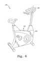
- FIG. 6is a perspective view of another embodiment of a patient exercise machine of the system of FIG. 1 ;
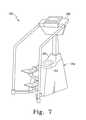
- FIG. 7is a perspective view of another embodiment of a patient exercise machine of the system of FIG. 1 ;
- FIG. 8is a simplified flowchart of one embodiment of an algorithm for transmitting orthopaedic implant sensor data used by an orthopaedic implant of the system of FIG. 1 ;
- FIG. 9is a simplified flowchart of one embodiment of an algorithm for monitoring orthopaedic implant sensor data used by the system of FIG. 1 .
- a system 10 for monitoring implant sensor dataincludes an orthopaedic implant 12 , a patient exercise machine 14 , and a controller 16 .
- the orthopaedic implant 12may be embodied as any type of orthopaedic implant such as, for example, a knee implant, a hip implant, a shoulder implant, or the like.
- An implant sensor 18 , a transmitter 20 , and other circuitry, as discussed in more detail below in regard to FIGS. 2 and 3are coupled to or otherwise housed in the orthopaedic implant 12 .
- the implant sensor 18may be embodied as any type of sensor capable of generating implant sensor data of a parameter of interest.
- the implant sensor 18may be embodied as a pressure sensor, a load sensor, a temperature sensor, a hall-effect sensor, or the like. It should be appreciated that although only a single sensor 18 is illustrated in FIG. 1 , in other embodiments, the system 10 may include any number of similar and/or different implant sensors coupled to or housed in the orthopaedic implant 12 .
- the transmitter 20may be embodied as or include any type of transmitter circuitry capable of transmitting the implant sensor data at a predetermined data rate or within a predetermined data rate range using a predetermined carrier frequency or range of frequencies. It should be appreciated that depending on the type and number of sensors used, the parameter of interest, the type and format of the implant sensor data, and the sampling rate employed, the transmitter 20 may be configured to transmit the implant data at any one or more of a number of different data rates and using any one or more of a number of different carrier frequencies.
- the patient exercise machine 14may be embodied as any type of exercise machine on which the patient may exercise.
- the patient exercise machine 14may be embodied as a treadmill, a stairstepper machine, a stationary bicycle, an elliptical trainer, a rowing machine, a ski machine, or the like.
- a primary coil 22 and an antenna 24are coupled to the patient exercise machine 14 .
- the primary coil 22may be embodied as any type of primary coil capable of being inductively coupled to a secondary coil (not shown in FIG. 1 ) housed in or coupled to the orthopaedic implant 12 and generating a current therein.
- the primary coil 22may be portable rather than coupled to the patient exercise machine 14 .
- the primary coil 22is configured to be held by a healthcare provider and in the vicinity of the implant 12 while the patient is exercising on the patient exercise machine 14 .
- the primary coil 22may embodied as, for example, a toroidal primary coil configured to receive a limb of the patient or a “c”-shaped primary coil configured to be held by a healthcare provider as described in detail in U.S. patent application Ser. No. 11/172,316 entitled “APPARATUS, SYSTEM, AND METHOD FOR TRANSCUTANEOUSLY TRANSFERRING ENERGY,” which was filed on Jun.
- the primary coil 22includes two patches couplable to the skin of the patient in the vicinity of the orthopaedic implant 12 .
- the patcheseach include a Helmholtz-like coil and are powered such that the Helmholtz coils produce an isotropic magnetic field, which is received by the secondary coil of the implant 12 .
- the antenna 24may be embodied as a loop antenna, a monopole antenna, or a patch antenna depending upon the data rate and/or carrier frequency utilized by the transmitter 20 and/or sensor 18 . That is, as described in more detail below in regard to FIGS. 4-6 , the antenna 24 is selected based the predetermined data rate or range of data rates and/or carrier frequency or range of frequencies used by the orthopaedic implant 12 . As such, the antenna 24 may have an increased sensitivity, a reduced size, or the like compared to other antennas used in a particular embodiment.
- the antenna 24is communicatively coupled to the controller 16 via communication links 26 .
- the primary coil 22is communicatively coupled to the controller 16 via communication links 28 .
- the communications links 24 , 26may be embodied as any type of communication links capable of facilitating electrical communication between the antenna 24 and the controller 16 and between the primary coil 22 and the controller 16 , respectively.
- the communication link 24 , 26may be embodied as or otherwise include any number of wires, cables, printed circuit board traces, vias, and/or the like.
- the controller 16includes a processor 30 and a memory device 32 .
- the processor 30may be embodied as any type of processor including, for example, discrete processing circuitry (e.g., a collection of logic devices), general purpose integrated circuit(s), and/or application specific integrated circuit(s) (i.e., ASICs).
- the memory device 32may be embodied as any type of memory device and may include one or more memory types, such as, random access memory (i.e., RAM) and/or read-only memory (i.e., ROM).
- the controller 16may include other devices and circuitry typically found in a computer for performing the functions described herein such as, for example, a hard drive, input/output circuitry, and the like.
- the controller 16is communicatively coupled with a display device 34 via a communication link 36 .
- the display device 34may form a portion of the controller 16 in some embodiments. Additionally or alternatively, the display device 34 or an additional display device may be positioned away from the controller 16 .
- the display device 34may be coupled with the ceiling or wall of the examination room wherein the orthopaedic examination procedure is to be performed. Additionally or alternatively, the display device 34 may be embodied as a virtual display such as a holographic display, a body mounted display such as a heads-up display, or the like.
- the controller 16may also be coupled with a number of input devices such as a keyboard and/or a mouse for providing data input to the controller 16 .
- the controller 16is also communicatively coupled to a patient database 40 via a network 42 .
- the patient database 40may be embodied as any type of database capable of storing patient-related data. Although illustrated in FIG. 1 as a single database, it should be appreciated that the patient database 40 may be embodied as any number of separate databases, file folders, flat files, or other storage locations.
- Such patient-related datamay include, for example, the implant sensor data received from the orthopaedic implant 12 and other data derived therefrom such as graphs, charts, and the like.
- the patient-related datamay be stored in the database 40 in association with, indexed by, or otherwise retrievable based on patient identification data such as the patient's name, address, etc.
- the patient database 40may be located in the doctor's office or hospital wherein the system 10 is incorporated or may be located remotely therefrom. In one particular embodiment, the patient database 40 forms a portion of a hospital network that is accessible by the controller 16 via the network 42 .
- the network 42may be embodied as any type of network capable of facilitating communication between the controller 16 and the patient database 40 .
- the network 42may be a local area network (LAN), a wide area network (WAN), or form a portion of a publicly-accessible, global network such as the Internet.
- the network 42may be a wired network, a wireless network, or a combination thereof.
- the network 42is embodied as or forms a portion of a hospital network and, as such, may include additional computers, routers, communication links, and/or the like.
- the controller 16is communicatively coupled to the network 42 via a number of communication links 44 .
- the patient database 40is communicatively coupled to the network 42 via any number of communication links 46 .
- the communication links 44 , 46may be any type of communication links capable of facilitating communication between the controller 16 and the patient database 40 .
- the communication links 44 , 46may be embodied as any number of wires, cables such as fiber optic cables, or the like. Additionally, any one or more of the communication links 44 , 46 may be embodied as wired or wireless communication links.
- the controller 16 and/or the patient database 40may include a wireless transmitter and/or receiver to facilitate wireless communication with the network 42 .
- the system 10is usable by a healthcare provider such as an orthopaedic surgeon, doctor, or nurse to monitor implant sensor data received from the orthopaedic implant 12 .
- the controller 16is configured to provide a power signal to the primary coil 22 via the communication link 28 .
- the primary coil 22is located in a position near the orthopaedic implant 12 , which is implanted in the patient, while the patient is operating the patient exercise machine 14 .
- the primary coil 22may be so positioned by an orthopaedic healthcare provider or, in some embodiments, may be coupled to the patient exercise machine 14 in an appropriate location.
- the primary coil 22is positioned in such a location that an electromagnetic field 48 generated by the primary coil 22 is capable of inductively coupling the primary coil 22 and a secondary coil located in or coupled to the orthopaedic implant 12 .
- the transmitter 20is configured to transmit implant sensor data received from the sensor 18 to the antenna 24 via a wireless communication link 50 .
- the transmitter 20may be configured to transmit the implant sensor data at a data rate or range of data rates and/or at a carrier frequency or range of frequencies based on, for example, the type and number of implant sensors used, the parameter of interest, the type and format of the implant sensor data, and the sampling rate employed.
- the controller 16receives the implant data via the antenna 24 and communication link 26 .
- the controller 16may be configured to display the implant sensor data, indicia thereof, or other data determined based on the implant sensor data on the display device 34 .
- the controller 16may be configured to display a graph or chart determined based on the implant data on the display device 34 .
- the controller 16may be configured to store the implant data in the memory device 32 .
- the controller 16may be configured to transmit the implant data to the patient database via the network 42 for storage therein.
- the orthopaedic implant 12includes a transmitter circuit 60 , an antenna 62 , a power coil 64 , and one or more implant sensors 66 .
- the transmitter circuit 60is communicatively coupled to the antenna 62 via a number of communication links 68 , to the power coil 64 via a number of communication links 70 , and to the implant sensor(s) 66 via a number of communication links 72 .
- the communication links 68 , 70 , 72may be embodied as any type of communication links capable of facilitating communication between the transmitter circuit 60 and the antenna 62 , power coil 64 , and the implant sensor(s) 66 , respectively.
- the communication links 68 , 70 , 72may be embodied as wires, cables, printed circuit board (PCB) traces, fiber optic cables, or the like.
- the transmitter circuit 60may be embodied as or include any type of transmitter circuitry capable of transmitting the implant sensor data received from the implant sensor(s) 66 at a predetermined data rate or within a predetermined data rate range using a predetermined carrier frequency or range of frequencies.
- the particular data rate or range of data rate usedmay be determined based on, for example, the type and number of implant sensors 66 used, the parameter of interest, the type and format of the implant sensor data, and the sampling rate employed.
- the transmitter circuit 60is configured to transmit the implant sensor data using a data rate less than 100 kilobytes per second.
- the transmitter circuit 60is configured to transmit the implant sensor data using a data rate in the range of 100 kilobytes per second to 1,000 kilobytes per second. In a further embodiment, the transmitter circuit 60 is configured to transmit the implant sensor data using a data rate greater than 1,000 kilobytes per second.
- the transmitter circuit 60may be configured to transmit the implant sensor data using a predetermined carrier frequency or range of frequencies.
- the transmitter circuit 60is configured to transmit the implant sensor data using a frequency or range of frequencies in or below the Very Low Frequency (VLF) band (e.g., using a frequency below 30,000 hertz).
- VLFVery Low Frequency
- the transmitter circuit 60is configured to transmit the implant sensor data using a frequency or range of frequencies in the Very High Frequency (VHF) or the lower Ultra High Frequency (UHF) band (e.g., using a frequency in the range of 30 mega-hertz to 2,000 mega-hertz).
- the transmitter circuit 60is configured to transmit the implant sensor data using a frequency or range of frequencies in the higher Ultra High Frequency (UHF) band (e.g., using a frequency greater than 2 giga-hertz).
- the transmitter circuitry 60may include additional circuitry such as processing circuitry or the like. However, in other embodiments, the transmitter circuit 60 may be embodied as a simple inductor-capacitor (LC) circuit or a crystal oscillator circuit and associated circuitry.
- LCinductor-capacitor
- the transmitter circuit 60receives power via the power coil 64 .
- the power coil 64is configured to be inductively coupled to the primary coil 22 when the primary coil 22 receives a power signal from the controller 16 .
- the power coil 64may include any number of individual coils.
- the power coil 64may include a single coil that is inductively coupled to the external primary coil 22 by positioning the primary coil 22 near the skin of the patient such that the power coil 64 lies within the alternating current (AC) electromagnetic field 48 generated by the primary coil 22 .
- the power coil 64includes more than a single coil to thereby improve the inductive coupling of the power coil 64 and the primary coil 22 .
- the power coil 64is embodied as three separate coils positioned orthogonally with respect to each other.
- the primary coil 22may be embodied as any type of power source capable of inductively coupling with the power coil 64 and generating a current therein.
- the implant sensor 66may be embodied as any number and type of sensor(s) capable of generating implant sensor data of a parameter of interest.
- the implant sensor 66may be embodied as a pressure sensor, a load sensor, a temperature sensor, a hall-effect sensor, or the like.
- the implant sensor 66may continually, periodically, or responsively generate the implant data.
- the implant sensor 66is configured to generate the implant data only while the power coil 64 is inductively coupled to the primary coil 22 .
- the orthopaedic implant 12also includes a memory device 67 .
- the memory device 67is communicatively coupled to the transmitter circuitry 60 via a number of communication links 73 , which may be embodied as any type of communication links capable of facilitating communication between the transmitter circuitry 60 and the memory device 67 such as, for example, wires, cables, printed circuit board (PCB) traces, fiber optic cables, or the like.
- the memory device 67may be embodied as any type of memory device and may include one or more memory types, such as, random access memory (i.e., RAM) and/or read-only memory (i.e., ROM).
- the transmitter circuitry 60may be configured to store implant sensor data received from the implant sensor(s) 66 in the memory device 67 .
- the stored implant sensor datamay be subsequently retrieved from the memory device 67 and transmitted via the transmitter circuitry 60 as discussed above.
- the orthopaedic implant 12includes a transmitter circuit 80 , a switching circuit 82 , a power/antenna coil 84 , and one or more implant sensors 86 .
- the transmitter circuit 80is communicatively coupled to the switching circuit 82 via a number of communication links 88 and to the implant sensor(s) 86 via a number of communication links 92 .
- the switching circuit 82is coupled to the power/antenna coil 84 via a number of communication links 90 . Similar to the communication links 68 , 70 , 72 described above in regard to FIG.
- the communication links 88 , 90 , 92may be embodied as any type of communication links capable of facilitating communication between the transmitter circuit 80 , the switching circuit 82 , the power/antenna coil 84 , and the implant sensor(s) 86 .
- the communication links 88 , 90 , 92may be embodied as wires, cables, printed circuit board (PCB) traces, fiber optic cables, or the like.
- the transmitter circuit 80is substantially similar to the transmitter 60 described above in regard to FIG. 2 and, as such, may be embodied as or include any type of transmitter circuit capable of transmitting the implant sensor data received from the implant sensor(s) 86 at a predetermined data rate or within a predetermined data rate range using a predetermined carrier frequency or range of frequencies.
- the particular data rate or range of data rate usedmay be determined based on, for example, the type and number of implant sensors 86 used, the parameter of interest, the type and format of the implant sensor data, and the sampling rate employed.
- the transmitter circuit 80is configured to transmit the implant sensor data using a data rate less than 100 kilobytes per second.
- the transmitter circuit 80is configured to transmit the implant sensor data using a data rate in the range of 100 kilobytes per second to 1,000 kilobytes per second. In a further embodiment, the transmitter circuit 80 is configured to transmit the implant sensor data using a data rate greater than 1,000 kilobytes per second.
- the transmitter circuit 80may be configured to transmit the implant sensor data using a predetermined carrier frequency or range of frequencies.
- the transmitter circuit 80is configured to transmit the implant sensor data using a frequency or range of frequencies in or below the Very Low Frequency (VLF) band (e.g., using a frequency below 30,000 hertz).
- VLFVery Low Frequency
- the transmitter circuit 80is configured to transmit the implant sensor data using a frequency or range of frequencies in the Very High Frequency (VHF) or the lower Ultra High Frequency (UHF) band (e.g., using a frequency in the range of 30 mega-hertz to 2,000 mega-hertz).
- the transmitter circuit 80is configured to transmit the implant sensor data using a frequency or range of frequencies in the higher Ultra High Frequency (UHF) band (e.g., using a frequency greater than 2 giga-hertz).
- the transmitter circuitry 80may include additional circuitry such as processing circuitry or the like. However, in other embodiments, the transmitter circuit 80 may be embodied as a simple inductor-capacitor (LC) circuit or a crystal oscillator circuit and associated circuitry.
- LCinductor-capacitor
- the implant sensor 86may be embodied as any number and type of sensor capable of generating implant sensor data of a parameter of interest.
- the implant sensor 86may be embodied as a pressure sensor, a load sensor, a temperature sensor, a hall-effect sensor, or the like.
- the implant sensor 86may be continually, periodically, or responsively generate the implant data.
- the implant sensor 86is configured to generate the implant data only while the power/power coil 64 is inductively coupled to the primary coil 22 .
- the transmitter circuit 80receives power and transmits the implant data the same coil, i.e., the power/antenna coil 84 .
- the switching circuit 82is operable to connect the power/antenna coil 84 to a power terminal(s) or port of the transmitter circuit 80 when power is to be provided thereto and to connect the power/antenna coil 84 to an output terminal(s) or port of the transmitter circuit 80 when power is not being provided and transmission of the wireless signal is desired.
- the switching circuit 82may include a coil or other device responsive to the magnetic field generated by the primary coil 22 to switch the connection of the power/antenna coil 84 from the output terminal of the transmitter circuit 80 to the power terminal.
- the power/antenna coil 84is inductively coupled with the primary coil 22 and connected to the power terminal of the transmitter circuit 80 via the switching circuit 82 .
- the orthopaedic implant 12may also include a memory device 87 in some embodiments.
- the memory device 87is communicatively coupled to the transmitter circuitry 80 via a number of communication links 93 , which may be embodied as any type of communication links capable of facilitating communication between the transmitter circuitry 80 and the memory device 87 such as, for example, wires, cables, printed circuit board (PCB) traces, fiber optic cables, or the like.
- the memory device 87may be embodied as any type of memory device and may include one or more memory types, such as, random access memory (i.e., RAM) and/or read-only memory (i.e., ROM).
- the transmitter circuitry 80may be configured to store implant sensor data received from the implant sensor(s) 86 in the memory device 87 .
- the stored implant sensor datamay be subsequently retrieved from the memory device 87 and transmitted via the transmitter circuitry 80 as discussed above.
- the orthopaedic implant 12may include more than one implant sensor 18 , 66 , 86 in some embodiments.
- the orthopaedic implant 12may include a switching circuit 400 communicatively coupled to each implant sensor 402 via a number of communication links 404 .
- the switching circuit 400is controlled by a processor 406 to selectively couple any one or more of the implant sensors 402 to the processor 406 via a number of communication links 408 .
- the processor 406is also communicatively coupled to a power coil 410 , a transmitter circuitry and antenna 414 , and a memory device 418 via a number of communication links 412 , 416 , 420 , respectively.
- the communication links 404 , 408 , 412 , 416 , and 420may be any type of communication capable of facilitating electrical communication between the devices of the orthopaedic implant 12 .
- the communication links 404 , 408 , 412 , 416 , 420may be embodied as or otherwise include any number of wires, cables, printed circuit board traces, vias, and/or the like.
- the processormay be embodied as any type of processor including, for example, discrete processing circuitry (e.g., a collection of logic devices), general purpose integrated circuit(s), and/or application specific integrated circuit(s) (i.e., ASICs).
- the memory device 418is similar to the memory devices 67 , 87 described above in regard to FIGS. 2 and 3 and may be embodied as any type of memory device and include one or more memory types, such as, random access memory (i.e., RAM) and/or read-only memory (i.e., ROM).
- the power coil 410is substantially similar to the power coil 64 described above in regard to FIG.
- the transmitter circuitry and antenna 414is substantially similar to the transmitter circuitry 60 and antenna 62 described above in regard to FIG. 2 and, as such, may be embodied as or include any type of transmitter circuit capable of transmitting the implant sensor data received from the implant sensor(s) 402 at a predetermined data rate or within a predetermined data rate range using a predetermined carrier frequency or range of frequencies. It should be appreciated that although the orthopaedic implant 12 illustrated in FIG. 4 includes a separate power coil 410 and transmitter antenna, in other embodiments, a power/antenna coil similar to the power/antenna coil 84 illustrated in and described above in regard to FIG. 3 may be used instead.
- the processor 406is configured to be responsive to a control signal received from the transmitter circuitry 414 to control the switching circuit 400 .
- the processor 406may control the switching circuit 400 to thereby couple any one or more of the sensors 402 to the processor 406 such that the processor 406 receives the implant sensor data from the coupled sensors 402 .
- the orthopaedic implant 12may be programmed to transmit data from all of the sensors 402 or from a selective number of the sensors 402 .
- an orthopaedic healthcare provideris able to monitor the implant sensor data from any one or more of the sensors 402 as described in more detail below in regard to FIGS. 8 and 9 .
- the orthopaedic implant 12includes an internal power source (not shown).
- the internal power sourcemay be embodied as, for example, a battery or the like and electrically coupled to the transmitter circuit 60 , 80 or processor 406 to provide power thereto.
- FIGS. 5-7several embodiments of particular patient exercise machines will be described. It should be appreciated, however, that the type of patient exercise machines so described are only exemplary and that, in other embodiments, other types of patient exercise machines may be used with any of the combination of antennas, transmitters, implant sensors, data rates, and/or carrier frequencies described below.
- the patient exercise machine 14is embodied as a treadmill 100 .
- the treadmill 100includes a loop antenna 102 coupled to a first longitudinal side 104 of a frame 106 of the treadmill 100 .
- the loop antenna 102is coupled to the frame 106 in a location such that the loop antenna 102 is in the vicinity of the orthopaedic implant 12 when the patient is operating the treadmill 100 .
- the loop antenna 102is positioned for communication with orthopaedic implants 12 located in the lower portion of the body of the patient (e.g., a knee implant).
- the loop antenna 102may be positioned for communication with orthopaedic implants 12 located in other portions of the patient's body.
- the loop antenna 102may be coupled to the frame 106 in a more upwardly location.
- the loop antenna 102may be movably coupled to the frame 106 such that the location of the loop antenna 102 relative to the patient may be altered.
- the treadmill 100may include a second loop antenna 108 coupled to a second longitudinal side 110 of the frame 106 .
- the treadmill 100is configured for communication with an orthopaedic implant 12 using a relatively low data rate and carrier frequency. That is, in embodiments of the system 10 wherein the sensor 18 , 66 , 86 is configured to generate the implant sensor data at a data rate of less than 100 kilobytes per second and/or the transmitter 20 , 60 , 80 , 414 is configured to transmit the implant sensor data using a carrier frequency lower than 30,000 hertz, the antenna 24 of the patient exercise machine 14 is embodied as a loop antenna (e.g., loop antenna 102 ).
- the antenna 24 of the patient exercise machine 14is embodied as a loop antenna (e.g., loop antenna 102 ).
- the implant data signal transmitted by the transmitter 20 , 60 , 80 , 414may be less attenuated due to passage of the signal through skin of the patient.
- the use of a lower carrier frequencymay also reduce the amount of heat generated.
- a relatively lower data ratee.g., less than 100 kilobytes per second
- a relatively lower carrier frequencye.g., less than 30,000 hertz
- the reception of the system 10may be improved by use of a loop antenna when a relatively low data rate (e.g., less than 100 kilobytes per second) and/or a relatively low carrier frequency (e.g., less than 30,000 hertz) are used due to the improved sensitivity of a loop antenna to low frequency and low power signals.
- a relatively low data ratee.g., less than 100 kilobytes per second
- a relatively low carrier frequencye.g., less than 30,000 hertz
- the loop antenna 102may be coupled to any one of a number of different types of patient exercise machines including, but not limited to, a treadmill, a stairstepper machine, a stationary bicycle, an elliptical trainer, a rowing machine, a ski machine, or the like.
- the patient exercise machine 14is illustratively embodied as a stationary bike 200 .
- the stationary bike 200includes a monopole antenna 202 coupled to a frame 204 of the bike 200 .
- the monopole antenna 202is coupled to the frame 204 in a location such that the monopole antenna 202 is in the vicinity of the orthopaedic implant 12 when the patient is operating the stationary bike 200 .
- the monopole antenna 202is positioned for communication with orthopaedic implants 12 located in the lower portion of the body of the patient (e.g., a knee implant).
- the monopole antenna 202may be positioned for communication with orthopaedic implants 12 located in other portions of the patient's body.
- the monopole antenna 202may be coupled to the frame 204 in a more upwardly location such as on a display panel 208 of the stationary bike 200 as indicated in FIG. 6 by monopole antenna 206 .
- the monopole antenna 202may be movably coupled to the frame 204 such that the location of the monopole antenna 202 relative to the patient may be altered.
- the stationary bike 200may include multiple monopole antennas (e.g., monopole antennas 204 and 206 ) in some embodiments to improve the reception of the implant sensor data from the orthopaedic implant 12 .
- the stationary bike 200is configured for communication with an orthopaedic implant 12 using a relatively medium data rate and carrier frequency. That is, in embodiments of the system 10 wherein the sensor 18 , 66 , 86 is configured to generate the implant sensor data at a data rate in the range of 100 kilobytes per second to 1,000 kilobytes per second and/or the transmitter 20 , 60 , 80 , 414 is configured to transmit the implant sensor data using a carrier frequency in the range of 30 mega-hertz to 2,000 mega-hertz, the antenna 24 of the patient exercise machine 14 is embodied as a monopole antenna (e.g., monopole antenna 202 and/or 206 ).
- a monopole antennae.g., monopole antenna 202 and/or 206
- a relatively medium carrier frequencye.g., in the range of 30 to 2,000 mega-hertz
- a larger bandwidthmay be used to transmit the increased amount of implant sensor data.
- the increased bandwidthmay allow “burst” implant data signal transmission during periods when an increase in the amount of data is desired.
- the monopole antenna 202may have a decreased overall size compared to the loop antenna 102 .
- the operation of the patient exercise machine 14 by a patientmay be improved by use of a monopole antenna when a relatively medium data rate (e.g., in the range of 100 kilobytes per second to 1,000 kilobytes per second) and/or a relatively medium carrier frequency (e.g., in the range of 30 to 2,000 mega-hertz) due to the decreased size of the monopole antenna.
- a relatively medium data ratee.g., in the range of 100 kilobytes per second to 1,000 kilobytes per second
- a relatively medium carrier frequencye.g., in the range of 30 to 2,000 mega-hertz
- the monopole antenna 202may be coupled to any one of a number of different types of patient exercise machines including, but not limited to, a treadmill, a stairstepper machine, a stationary bicycle, an elliptical trainer, a rowing machine, a ski machine, or the like. Additionally, it should be appreciated that the monopole antenna 202 may be any type of monopole antenna 202 able to be coupled to a patient exercise machine.
- the monopole antenna 202is embodied as a half-wave monopole antenna to further reduce the overall size of the antenna.
- other types of monopole antennassuch as a quarter-wave monopole antenna, a fifth-eighths-wave monopole antenna, or the like, may be used.
- the patient exercise machine 14is illustratively embodied as a stairstepper machine 300 .
- the stairstepper machine 300includes a patch antenna 302 coupled to a frame 304 of the stairstepper machine 300 .
- the patch antenna 302is coupled to or positioned in a panel 306 , which is coupled to the frame 304 , in a location such that the patch antenna 302 is in the vicinity of the orthopaedic implant 12 when the patient is operating the stairstepper machine 300 .
- FIG. 1the illustrative embodiment of FIG.
- the patch antenna 302is positioned for communication with orthopaedic implants 12 located in the lower portion of the body of the patient (e.g., a knee implant).
- the patch antenna 202may be positioned for communication with orthopaedic implants 12 located in other portions of the patient's body.
- the patch antenna 302may be coupled to the frame 304 in a more upwardly location such as on a display panel 308 of the stairstepper machine 300 .
- the patch antenna 302may be movably coupled to the frame 304 such that the location of the patch antenna 302 relative to the patient may be altered.
- the stairstepper machine 300may include multiple patch antennas in some embodiments to improve the reception of the implant sensor data from the orthopaedic implant 12 .
- the stairstepper machine 300is configured for communication with an orthopaedic implant 12 using a relatively high data rate and carrier frequency. That is, in embodiments of the system 10 wherein the sensor 18 , 66 , 86 is configured to generate the implant sensor data at a data rate greater than 1,000 kilobytes per second and/or the transmitter 20 , 60 , 80 , 414 is configured to transmit the implant sensor data using a carrier frequency greater than 2 giga-hertz, the antenna 24 of the patient exercise machine 14 is embodied as a patch antenna (e.g., patch antenna 302 ).
- a relatively high carrier frequencye.g., greater than 2 giga-hertz
- a larger bandwidthmay be used to transmit the increased amount of implant sensor data.
- the increased bandwidthmay allow and increased amount of “burst” implant data signal transmission during periods when an increase in the amount of data is desired.
- the patch antenna 202may have a decreased overall size compared to the loop antenna 102 and/or the monopole antenna 302 .
- the operation of the patient exercise machine 14 by a patientmay be improved by use of a patch antenna when a relatively high data rate (e.g., greater than 1,000 kilobytes per second) and/or a relatively high carrier frequency (e.g., greater than 2 giga-hertz) due to the decreased size of the patch antenna.
- a relatively high data ratee.g., greater than 1,000 kilobytes per second
- a relatively high carrier frequencye.g., greater than 2 giga-hertz
- the patch antenna 302may be coupled to any one of a number of different types of patient exercise machines including, but not limited to, a treadmill, a stairstepper machine, a stationary bicycle, an elliptical trainer, a rowing machine, a ski machine, or the like.
- the orthopaedic implant 12may be configured to execute an algorithm 500 for transmitting sensor data.
- the algorithm 500begins with a process step 502 in which the transmitter circuitry 20 , 60 , 80 , 414 activates when a power signal has been received from the power coil 64 , 84 via the communication links 70 , 90 .
- the power coil 64 , 85generates the power signal when the coil 64 , 84 is inductively coupled to the primary coil 22 .
- the algorithm 500advances to process step 504 when a power signal has been received.
- the transmitter circuitry 20 , 60 , 80 , 414receives implant sensor data from the implant sensor(s) 18 , 66 , 86 via the communication links 72 , 92 .
- the implant sensor datamay be, for example, pressure data, temperature data, or the like.
- the implant sensor datais transmitted by the transmitter circuitry 20 , 60 , 80 , 414 to the antenna 24 (e.g., the loop antenna 102 , the monopole antenna 202 , or the patch antenna 304 depending on the particular embodiment) using the antenna 62 or the power/antenna coil 84 .
- the transmitter circuitry 20 , 60 , 80 , 414may be configured to transmit the implant sensor data at a predetermined data rate or within a predetermined data rate range using a predetermined carrier frequency or range of frequencies. For example, as discussed in detail above in regard to FIG.
- the transmitter circuitry 20 , 60 , 80 , 414may be configured to transmit the implant sensor data using a data rate less than 100 kilobytes per second and/or a carrier frequency less than 30,000 hertz.
- the transmitter circuitry 20 , 60 , 80 , 414may be configured to transmit the implant sensor data using a data rate in the range of 100 kilobytes per second to 1,000 kilobytes per second and/or a carrier frequency in the range of 30 mega-hertz to 2,000 mega-hertz.
- the transmitter circuitry 20 , 60 , 80 , 414may be configured to transmit the implant sensor data using a data rate greater than 1,000 kilobytes per second and/or a carrier frequency greater than 2 giga-hertz.
- the algorithm 500loops back to process step 502 in which the transmitter circuitry 20 , 60 , 80 , 414 determines if another power signal has been received or is still being received from the power coil 64 , 84 , 410 .
- the transmitter circuitry 20 , 60 , 80 , 414is configured to periodically transmit the implant sensor data while power coil 64 , 84 , 410 is indicatively coupled to the primary coil 22 .
- the orthopaedic implant 12i.e., the transmitter circuitry 20 , 60 , 80 , 414 ) will transmit implant sensor data to the antenna 24 , which is received by the controller 16 via the communication links 26 .
- the algorithm 500also advances to process step 508 and 514 once a power signal has been received.
- the process steps 504 , 508 , 514may be executed in a sequential order or contemporaneously with each other once a power signal is received.
- the orthopaedic implant 12determines if any stored implant sensor data should be transmitted to the antenna 24 (e.g., the loop antenna 102 , the monopole antenna 202 , or the patch antenna 304 depending on the particular embodiment).
- the transmitter circuitry 20 , 60 , 80 , 414 and/or processor 406may be programmed or otherwise configured to transmit or not transmit the stored implant sensor data. Additionally or alternatively, the transmitter circuitry 20 , 60 , 80 , 414 and/or processor 406 may be configured to access or otherwise retrieve data from the associated memory 67 , 87 , 418 and determine if the stored implant sensor data should be transmitted based on such data (e.g., based on the value of the retrieved data). In this way, the orthopaedic implant 12 may be programmed to transmit stored data or not to transmit stored data depending on the particular application and/or implementation of the system 10 and/or the orthopaedic implant 12 .
- the algorithm 500loops back to process step 502 in which the transmitter circuitry 20 , 60 , 80 , 414 and/or processor 406 determines if another power signal has been received or is still being received from the power coil 64 , 84 , 410 . If, however, the transmitter circuitry 20 , 60 , 80 , 414 and/or processor 406 determines that the implant sensor data stored in the memory device 67 , 87 , 418 should also be transmitted, the algorithm 500 advances to process step 510 .
- process step 510the implant sensor data stored in the memory device 67 , 87 , 418 is retrieved.
- the retrieved implant sensor datais subsequently transmitted to the antenna 24 in process step 512 .
- the algorithm 500loops back to process step 502 wherein the transmitter circuitry 20 , 60 , 80 , 414 determines if another power signal has been received or is still being received from the power coil 64 , 84 , 410 .
- the orthopaedic implant 12also determines if any programming data is available in some embodiments.
- the transmitter circuitry 60 , 80 , 414is embodied as or otherwise includes a transceiver configured to transmit and receive data from the antenna 24 . If the transmitter circuitry 20 , 60 , 80 , 414 and/or processor 406 determines that programming data is not available in process step 514 , the algorithm 500 loops back to process step 502 in which the transmitter circuitry 20 , 60 , 80 , 414 determines if another power signal has been received or is still being received from the power coil 64 , 84 , 410 .
- the algorithm 500advances to process step 516 .
- the orthopaedic implant 12receives programming data from the controller 16 via the antenna 24 .
- the transmitter circuitry 20 , 60 , 80 , 414 and/or processor 406is configured to update one or more programs or programming data used by the electronic circuitry of the orthopaedic implant 12 .
- the programming datamay be used by the processor 406 to control the switching circuit 400 such that the implant sensor data from any one or more implant sensors 402 may be monitored.
- the controller 16 of the system 10may execute an algorithm 600 for monitoring orthopaedic implant data. 10 .
- the algorithm 600begins with a process step 602 in which the primary coil 22 of the patient exercise machine 14 is inductively coupled with the secondary coil (e.g., the power coil 64 or the power/antenna coil 84 ) of the orthopaedic implant 12 .
- the controller 16is configured to transmit a power signal to the primary coil 22 via the communication link 28 to thereby energize the coil 22 .
- the primary coil 22In response, the primary coil 22 generates the electromagnetic field 48 , which is received by the secondary coil (e.g., the power coil 64 or the power/antenna coil 84 ) of the orthopaedic implant 12 .
- the controller 16may be configured to continuously energize the primary coil 22 , periodically energize the primary coil 22 , or selectively energize the primary coil 22 .
- the patient exercise machine 14may include a pressure or motion sensor configured to determine the presence of the patient. In such embodiments, the pressure, motion, or other sensor output is transmitted to the controller 16 and, in response, the controller 16 transmits the power signal to the primary coil 22 . In this way, the primary coil 22 is only energized when a patient is operating or in the vicinity of the patient exercise machine 14 .
- the controller 16determines if any implant sensor data is available (i.e., if any implant sensor data is being transmitted) in process step 604 . If not, the algorithm 600 loops back to the process step 602 wherein the controller 16 continuously, periodically, or selectively transmits the power signal to the primary coil 22 . However, if implant sensor data is being transmitted by the orthopaedic implant 12 , the algorithm 600 advances to process step 606 . In process step 606 , the implant sensor data is received from the orthopaedic implant 12 . That is, the implant sensor data is received by the antenna 24 (e.g., the loop antenna 102 , the monopole antenna 202 , or the patch antenna 302 ) of the patient exercise machine 14 and transmitted to the controller 16 via the communication links 26 .
- the antenna 24e.g., the loop antenna 102 , the monopole antenna 202 , or the patch antenna 302
- the implant sensor datais displayed to the healthcare provider on the display device 34 .
- the controller 16is configured to transmit the implant sensor data to the display device 34 via the communication links 36 .
- the controller 16may be configured to calculate or determine other data based on the implant sensor data. For example, in some embodiments, the controller 16 may be configured to determine a graph or chart based on the implant sensor data received from the orthopaedic implant sensor 12 and display the graph or chart to the healthcare provider on the display device 34 .
- the controller 16determines if the healthcare provider desires to record the implant sensor data in process step 610 .
- the healthcare providermay require that the implant sensor data be recorded by supplying the appropriate commands to the controller 16 via, for example, a keyboard, mouse, or other input device.
- the controller 16may be configured to always record the implant sensor data.
- the algorithm 600advances to process step 612 .
- the implant sensor data received from the orthopaedic implant sensor 12is temporarily stored in the memory device 32 or other storage location (e.g., hard drive, floppy disk, portable memory device, etc.) of the controller 16 .
- the implant sensor datamay be recorded for use in many different applications such as, for example, for calculating or determining other data such as a graph or chart of implant data received over a predetermined period of time or as temporary storage.
- the algorithm 600advances to process step 614 .
- the controller 16determines if the healthcare provider desires to store the implant sensor data. As described above, the healthcare provider may require that the implant sensor data be stored by supplying the appropriate commands to the controller 16 via, for example, a keyboard, mouse, or other input device. Alternatively, the controller 16 may be configured to always store the implant sensor data. Regardless, if the controller 16 has determined that the implant sensor data is to be stored, the algorithm 600 advances to process step 618 .
- the controller 16transmits the implant sensor data received from the orthopaedic implant sensor 12 to the patient database 40 via the communication links 44 , the network 42 , and the communication links 46 .
- the implant sensor datamay be stored in the patient database 40 for later use such as for examination by an orthopaedic surgeon or other healthcare provider.
- the implant sensor datamay be accessible from other locations (e.g., an orthopaedic surgery room) in the hospital once stored in the database 40 .
- the algorithm 600loops back to process step 602 in which the controller 16 is configured to transmit the power signal to the primary coil 22 .
- the controller 16is also configured to determine if the orthopaedic healthcare provider desires to program the orthopaedic implant in a process step 620 in some embodiments. If not, the algorithm 600 loops back to the process step 602 wherein the controller 16 continuously, periodically, or selectively transmits the power signal to the primary coil 22 . However, if controller 16 determines that the orthopaedic healthcare provider desires to program the orthopaedic implant 12 in process step 620 , the algorithm 600 proceeds to process step 622 . In process step 622 , the orthopaedic healthcare provider supplies the programming data to the controller 16 .
- the orthopaedic healthcare providermay supply the programming data via manually typing in the data or otherwise operating the controller 16 such that the programming data is transmitted to the orthopaedic implant 12 via the antenna 24 .
- the programming datais transmitted to the orthopaedic implant 12 via the antenna 24 in process step 624 .
- the programming datamay cause the orthopaedic implant 12 to transmit implant sensor data generated by one or more implant sensors 402 selected by the orthopaedic healthcare provider. In this way, the orthopaedic healthcare provider may individually monitor each of the orthopaedic implant sensors 402 while the patient is exercising on the patient excise machine 14 .
Landscapes
- Health & Medical Sciences (AREA)
- Engineering & Computer Science (AREA)
- Life Sciences & Earth Sciences (AREA)
- General Health & Medical Sciences (AREA)
- Biomedical Technology (AREA)
- Public Health (AREA)
- Medical Informatics (AREA)
- Primary Health Care (AREA)
- Epidemiology (AREA)
- Biophysics (AREA)
- Veterinary Medicine (AREA)
- Heart & Thoracic Surgery (AREA)
- Animal Behavior & Ethology (AREA)
- Business, Economics & Management (AREA)
- Molecular Biology (AREA)
- General Business, Economics & Management (AREA)
- Surgery (AREA)
- Physical Education & Sports Medicine (AREA)
- Computer Networks & Wireless Communication (AREA)
- Physics & Mathematics (AREA)
- Pathology (AREA)
- Cardiology (AREA)
- Oral & Maxillofacial Surgery (AREA)
- Vascular Medicine (AREA)
- Transplantation (AREA)
- Arrangements For Transmission Of Measured Signals (AREA)
- Measuring And Recording Apparatus For Diagnosis (AREA)
Abstract
Description
Claims (17)
Priority Applications (2)
| Application Number | Priority Date | Filing Date | Title |
|---|---|---|---|
| US11/530,567US8632464B2 (en) | 2006-09-11 | 2006-09-11 | System and method for monitoring orthopaedic implant data |
| EP07253590AEP1902673A3 (en) | 2006-09-11 | 2007-09-10 | System for monitoring orthopaedic implant data |
Applications Claiming Priority (1)
| Application Number | Priority Date | Filing Date | Title |
|---|---|---|---|
| US11/530,567US8632464B2 (en) | 2006-09-11 | 2006-09-11 | System and method for monitoring orthopaedic implant data |
Publications (2)
| Publication Number | Publication Date |
|---|---|
| US20080071146A1 US20080071146A1 (en) | 2008-03-20 |
| US8632464B2true US8632464B2 (en) | 2014-01-21 |
Family
ID=38780813
Family Applications (1)
| Application Number | Title | Priority Date | Filing Date |
|---|---|---|---|
| US11/530,567Active2031-10-16US8632464B2 (en) | 2006-09-11 | 2006-09-11 | System and method for monitoring orthopaedic implant data |
Country Status (2)
| Country | Link |
|---|---|
| US (1) | US8632464B2 (en) |
| EP (1) | EP1902673A3 (en) |
Cited By (1)
| Publication number | Priority date | Publication date | Assignee | Title |
|---|---|---|---|---|
| US20140379090A1 (en)* | 2011-08-08 | 2014-12-25 | Ecole Polytechnique Federale De Lausanne (Epfl) | In-vivo condition monitoring of metallic implants by electrochemical techniques |
Families Citing this family (3)
| Publication number | Priority date | Publication date | Assignee | Title |
|---|---|---|---|---|
| US20130197468A1 (en)* | 2012-01-26 | 2013-08-01 | Carnegie Mellon University | Device for Intramyocardial Delivery |
| WO2017218939A1 (en)* | 2016-06-16 | 2017-12-21 | Arizona Board Of Regents On Behalf Of The University Of Arizona | System, devices, and methods for coding and decoding motion activity and for detecting change in such |
| EP3399359B1 (en)* | 2017-05-03 | 2020-12-09 | TRUMPF Schweiz AG | Plug connection assembly and related monitoring process |
Citations (135)
| Publication number | Priority date | Publication date | Assignee | Title |
|---|---|---|---|---|
| US4352960A (en) | 1980-09-30 | 1982-10-05 | Baptist Medical Center Of Oklahoma, Inc. | Magnetic transcutaneous mount for external device of an associated implant |
| US4436684A (en) | 1982-06-03 | 1984-03-13 | Contour Med Partners, Ltd. | Method of forming implantable prostheses for reconstructive surgery |
| US4467809A (en) | 1982-09-17 | 1984-08-28 | Biolectron, Inc. | Method for non-invasive electrical stimulation of epiphyseal plate growth |
| US4549547A (en) | 1982-07-27 | 1985-10-29 | Trustees Of The University Of Pennsylvania | Implantable bone growth stimulator |
| US4573475A (en) | 1984-11-15 | 1986-03-04 | Hewlett-Packard Company | Receiving radiation from loops in a common plane for monitoring hospital patients leadlessly |
| US4830021A (en)* | 1988-08-29 | 1989-05-16 | Thornton William E | Monitoring system for locomotor activity |
| US4936862A (en) | 1986-05-30 | 1990-06-26 | Walker Peter S | Method of designing and manufacturing a human joint prosthesis |
| GB2239802A (en) | 1990-01-09 | 1991-07-17 | Univ Ottawa | Transcutaneous energy transfer device |
| US5211165A (en) | 1991-09-03 | 1993-05-18 | General Electric Company | Tracking system to follow the position and orientation of a device with radiofrequency field gradients |
| US5300120A (en) | 1992-08-24 | 1994-04-05 | Lipomatrix Incorporated | Implant with electrical transponder marker |
| GB2272575A (en) | 1992-11-02 | 1994-05-18 | Gec Ferranti Defence Syst | Dual band antenna |
| US5350379A (en) | 1993-02-18 | 1994-09-27 | Genesis Orthopedics | Bone and tissue lengthening device |
| US5356411A (en) | 1993-02-18 | 1994-10-18 | Spievack Alan R | Bone transporter |
| US5362996A (en) | 1992-06-10 | 1994-11-08 | Intel Corporation | Staggered output circuit for noise reduction |
| US5383915A (en) | 1991-04-10 | 1995-01-24 | Angeion Corporation | Wireless programmer/repeater system for an implanted medical device |
| US5448489A (en) | 1990-10-03 | 1995-09-05 | Board Of Regents, The University Of Texas System | Process for making custom joint replacements |
| US5488952A (en) | 1982-02-24 | 1996-02-06 | Schoolman Scientific Corp. | Stereoscopically display three dimensional ultrasound imaging |
| US5522402A (en) | 1994-05-13 | 1996-06-04 | Cooley; Robert A. | Three-dimensional scanning method for design of protheses |
| US5536269A (en) | 1993-02-18 | 1996-07-16 | Genesis Orthopedics | Bone and tissue lengthening device |
| US5542106A (en)* | 1994-09-15 | 1996-07-30 | Motorola, Inc. | Electronic device having an RF circuit integrated into a movable housing element |
| US5610996A (en) | 1991-04-15 | 1997-03-11 | Microsoft Corporation | Method and apparatus for arc segmentation in handwriting recognition |
| US5626579A (en) | 1993-02-12 | 1997-05-06 | The Cleveland Clinic Foundation | Bone transport and lengthening system |
| US5662111A (en) | 1991-01-28 | 1997-09-02 | Cosman; Eric R. | Process of stereotactic optical navigation |
| US5704939A (en) | 1996-04-09 | 1998-01-06 | Justin; Daniel F. | Intramedullary skeletal distractor and method |
| US5715837A (en) | 1996-08-29 | 1998-02-10 | Light Sciences Limited Partnership | Transcutaneous electromagnetic energy transfer |
| US5741215A (en) | 1993-09-10 | 1998-04-21 | The University Of Queensland | Stereolithographic anatomical modelling process |
| US5741316A (en) | 1996-12-02 | 1998-04-21 | Light Sciences Limited Partnership | Electromagnetic coil configurations for power transmission through tissue |
| US5798924A (en) | 1993-12-04 | 1998-08-25 | Eufinger; Harald | Process for producing endoprostheses |
| US5807258A (en) | 1997-10-14 | 1998-09-15 | Cimochowski; George E. | Ultrasonic sensors for monitoring the condition of a vascular graft |
| US5832488A (en) | 1995-03-29 | 1998-11-03 | Stuart S. Bowie | Computer system and method for storing medical histories using a smartcard to store data |
| US5855609A (en) | 1992-08-24 | 1999-01-05 | Lipomatrix, Incorporated (Bvi) | Medical information transponder implant and tracking system |
| US5961553A (en) | 1995-02-13 | 1999-10-05 | Medinov-Amp | Long bone elongation device |
| WO1999056614A1 (en) | 1998-05-07 | 1999-11-11 | Bpm Devices, Inc. | System including an implantable device and methods of use for determining blood pressure and other blood parameters of a living being |
| US6002859A (en) | 1997-02-21 | 1999-12-14 | Carnegie Mellon University | Apparatus and method facilitating the implantation of artificial components in joints |
| US6034296A (en)* | 1997-03-11 | 2000-03-07 | Elvin; Niell | Implantable bone strain telemetry sensing system and method |
| WO2000013585A1 (en) | 1998-09-04 | 2000-03-16 | Wolfe Research Pty. Ltd. | Medical implant system |
| US6083174A (en) | 1997-02-13 | 2000-07-04 | Sican Gmbh | Implantable measuring unit for intracorporal measurement of patient data |
| US6115636A (en) | 1998-12-22 | 2000-09-05 | Medtronic, Inc. | Telemetry for implantable devices using the body as an antenna |
| US6126690A (en) | 1996-07-03 | 2000-10-03 | The Trustees Of Columbia University In The City Of New York | Anatomically correct prosthesis and method and apparatus for manufacturing prosthesis |
| US6144385A (en) | 1994-08-25 | 2000-11-07 | Michael J. Girard | Step-driven character animation derived from animation data without footstep information |
| US6151581A (en) | 1996-12-17 | 2000-11-21 | Pulsegroup Inc. | System for and method of collecting and populating a database with physician/patient data for processing to improve practice quality and healthcare delivery |
| US6161080A (en) | 1997-11-17 | 2000-12-12 | The Trustees Of Columbia University In The City Of New York | Three dimensional multibody modeling of anatomical joints |
| US6177034B1 (en) | 1998-04-03 | 2001-01-23 | A-Pear Biometric Replications Inc. | Methods for making prosthetic surfaces |
| US6239705B1 (en) | 2000-04-19 | 2001-05-29 | Jeffrey Glen | Intra oral electronic tracking device |
| WO2001037926A1 (en) | 1999-11-22 | 2001-05-31 | Abiomed, Inc. | Apparatus for transferring energy across a boundary |
| US6254639B1 (en) | 1996-09-25 | 2001-07-03 | Ninian Peckitt | Prosthetic implants |
| WO2001049173A1 (en) | 2000-01-07 | 2001-07-12 | Imatec Ag | Device for in vivo measurement of pressures and pressure variations in or on bones |
| US20010051787A1 (en) | 1999-07-07 | 2001-12-13 | Markus Haller | System and method of automated invoicing for communications between an implantable medical device and a remote computer system or health care provider |
| US6336929B1 (en) | 1998-01-05 | 2002-01-08 | Orthodyne, Inc. | Intramedullary skeletal distractor and method |
| US20020024450A1 (en) | 1999-12-06 | 2002-02-28 | Townsend Christopher P. | Data collection and storage device |
| US6366799B1 (en) | 1996-02-15 | 2002-04-02 | Biosense, Inc. | Movable transmit or receive coils for location system |
| US6369694B1 (en) | 1997-08-26 | 2002-04-09 | Digital Angel Corporation | Apparatus and method for remotely testing a passive integrated transponder tag interrogation system |
| US20020065539A1 (en)* | 2000-11-30 | 2002-05-30 | Von Arx Jeffrey A. | Telemetry apparatus and method for an implantable medical device |
| US6400272B1 (en) | 1999-04-01 | 2002-06-04 | Presto Technologies, Inc. | Wireless transceiver for communicating with tags |
| US20020077562A1 (en) | 2000-12-15 | 2002-06-20 | James Kalgren | System and method for correlation of patient health information and implant device data |
| US6442432B2 (en) | 1999-12-21 | 2002-08-27 | Medtronic, Inc. | Instrumentation and software for remote monitoring and programming of implantable medical devices (IMDs) |
| US6447448B1 (en) | 1998-12-31 | 2002-09-10 | Ball Semiconductor, Inc. | Miniature implanted orthopedic sensors |
| US20020128872A1 (en) | 2000-08-07 | 2002-09-12 | Giammattei Charles P. | Medical data recordation system |
| US20020135336A1 (en) | 2001-03-21 | 2002-09-26 | Digital Angel Corporation | System and method for remote monitoring utilizing a rechargeable battery |
| US6458161B1 (en) | 2001-02-23 | 2002-10-01 | Biomet, Inc. | Method and apparatus for acetabular reconstruction |
| US6459943B1 (en) | 1998-05-11 | 2002-10-01 | King Jim Co., Ltd. | Seal producing apparatus |
| US20020151770A1 (en) | 2001-01-04 | 2002-10-17 | Noll Austin F. | Implantable medical device with sensor |
| WO2002080753A2 (en) | 2001-04-04 | 2002-10-17 | Given Imaging Ltd. | Induction powered in vivo imaging device |
| US6474599B1 (en) | 2001-12-11 | 2002-11-05 | Gerald D. Stomski | Aircraft security system |
| US6480745B2 (en) | 1999-12-24 | 2002-11-12 | Medtronic, Inc. | Information network interrogation of an implanted device |
| WO2002091399A1 (en) | 2001-05-03 | 2002-11-14 | Berlin Heart Ag | Device for the subcutaneous transfer of energy or data |
| WO2002094113A1 (en) | 2001-05-23 | 2002-11-28 | Orthogon Technologies 2003 Ltd. | Magnetically-actuable intramedullary device |
| US20020198740A1 (en) | 2001-06-21 | 2002-12-26 | Roman Linda L. | Intelligent data retrieval system and method |
| US6529127B2 (en) | 1997-07-11 | 2003-03-04 | Microstrain, Inc. | System for remote powering and communication with a network of addressable, multichannel sensing modules |
| US20030045787A1 (en) | 2001-09-05 | 2003-03-06 | Schulze Arthur E. | Apparatus and method for recording an electrocardiogram using non-obtrusive sensors |
| US20030069644A1 (en) | 2001-10-05 | 2003-04-10 | Nebojsa Kovacevic | Dual-tray teletibial implant |
| US20030067736A1 (en) | 2000-03-31 | 2003-04-10 | Abb Technology Ag | Power supply arrangement |
| US6565576B1 (en) | 1998-12-04 | 2003-05-20 | Wittenstein Gmbh & Co. Kg | Distraction assembly |
| US6574511B2 (en) | 2000-04-21 | 2003-06-03 | Medtronic, Inc. | Passive data collection system from a fleet of medical instruments and implantable devices |
| GB2382777A (en) | 2001-12-07 | 2003-06-11 | Wyman Kwong | Referencing marker for use in computer assisted surgery |
| US20030154411A1 (en) | 2002-02-11 | 2003-08-14 | Hovik J. Kjell | Medical records categorization and retrieval system |
| US6656135B2 (en) | 2000-05-01 | 2003-12-02 | Southwest Research Institute | Passive and wireless displacement measuring device |
| US6674883B1 (en) | 2000-08-14 | 2004-01-06 | Siemens Corporate Research, Inc. | System and method for the detection of anatomic landmarks for total hip replacement |
| US20040008123A1 (en) | 2002-07-15 | 2004-01-15 | Battelle Memorial Institute | System and method for tracking medical devices |
| US20040011137A1 (en) | 2002-07-10 | 2004-01-22 | Hnat William P. | Strain sensing system |
| US20040019384A1 (en) | 2002-07-24 | 2004-01-29 | Bryan Kirking | Implantable prosthesis for measuring six force components |
| US6687131B1 (en) | 1999-05-14 | 2004-02-03 | Sokymat S.A. | Transponder and injection-molded part and method for manufacturing same |
| US20040030395A1 (en) | 2000-04-13 | 2004-02-12 | Gordon Blunn | Surgical distraction device |
| US6700547B2 (en) | 2002-04-12 | 2004-03-02 | Digital Angel Corporation | Multidirectional walkthrough antenna |
| WO2004026399A1 (en) | 2002-09-20 | 2004-04-01 | Potencia Medical Ag | Harmless wireless energy transmission to implant |
| US6720930B2 (en) | 2001-01-16 | 2004-04-13 | Digital Angel Corporation | Omnidirectional RFID antenna |
| US20040078219A1 (en) | 2001-12-04 | 2004-04-22 | Kimberly-Clark Worldwide, Inc. | Healthcare networks with biosensors |
| US20040106967A1 (en) | 2002-12-03 | 2004-06-03 | Von Arx Jeffrey A. | Antenna systems for implantable medical device telemetry |
| US6750866B1 (en) | 2000-04-21 | 2004-06-15 | Realistic Dynamics, Inc. | Method and system for dynamically filtering the motion of articulated bodies |
| US20040113790A1 (en) | 2002-09-23 | 2004-06-17 | Hamel Michael John | Remotely powered and remotely interrogated wireless digital sensor telemetry system |
| US20040133081A1 (en)* | 2002-10-09 | 2004-07-08 | Eric Teller | Method and apparatus for auto journaling of continuous or discrete body states utilizing physiological and/or contextual parameters |
| US20040138925A1 (en) | 2002-12-23 | 2004-07-15 | Zheng Shu Sean | Resources utilization management system and method of use |
| US6772002B2 (en) | 2000-11-24 | 2004-08-03 | Brainlab Ag | Device and method for navigation |
| US20040152972A1 (en) | 2003-01-30 | 2004-08-05 | Mark Hunter | Method and apparatus for post-operative tuning of a spinal implant |
| US20040171924A1 (en) | 2003-01-30 | 2004-09-02 | Mire David A. | Method and apparatus for preplanning a surgical procedure |
| US20040178955A1 (en) | 2003-03-11 | 2004-09-16 | Alberto Menache | Radio Frequency Motion Tracking System and Mehod. |
| US6793496B2 (en) | 1999-04-15 | 2004-09-21 | General Electric Company | Mathematical model and a method and apparatus for utilizing the model |
| US6799066B2 (en) | 2000-09-14 | 2004-09-28 | The Board Of Trustees Of The Leland Stanford Junior University | Technique for manipulating medical images |
| US6804558B2 (en) | 1999-07-07 | 2004-10-12 | Medtronic, Inc. | System and method of communicating between an implantable medical device and a remote computer system or health care provider |
| US20040230226A1 (en) | 1998-03-24 | 2004-11-18 | Ehti Medical Corporation | RF diathermy and faradic muscle stimulation treatment |
| US6833790B2 (en) | 2002-04-12 | 2004-12-21 | Digital Angel Corporation | Livestock chute scanner |
| US20050010299A1 (en)* | 2003-07-11 | 2005-01-13 | Disilvestro Mark R. | In vivo joint implant cycle counter |
| US20050010300A1 (en) | 2003-07-11 | 2005-01-13 | Disilvestro Mark R. | Orthopaedic element with self-contained data storage |
| US20050012610A1 (en) | 2003-07-11 | 2005-01-20 | Yen-Shuo Liao | Joint endoprosthesis with ambient condition sensing |
| US6847892B2 (en) | 2001-10-29 | 2005-01-25 | Digital Angel Corporation | System for localizing and sensing objects and providing alerts |
| US20050027330A1 (en) | 2003-07-31 | 2005-02-03 | Assaf Govari | Encapsulated sensor with external antenna |
| US20050055316A1 (en) | 2003-09-04 | 2005-03-10 | Sun Microsystems, Inc. | Method and apparatus having multiple identifiers for use in making transactions |
| US20050065815A1 (en) | 2003-09-19 | 2005-03-24 | Mazar Scott Thomas | Information management system and method for an implantable medical device |
| US20050075697A1 (en) | 2003-10-02 | 2005-04-07 | Medtronic, Inc. | External power source for an implantable medical device having an adjustable carrier frequency and system and method related therefore |
| US20050091338A1 (en) | 1997-04-14 | 2005-04-28 | Carlos De La Huerga | System and method to authenticate users to computer systems |
| US20050101962A1 (en) | 2003-11-10 | 2005-05-12 | Thorsten Schwenke | Servo-controlled impacting device for orthopedic implants |
| US20050099290A1 (en) | 2003-11-11 | 2005-05-12 | Biosense Webster Inc. | Digital wireless position sensor |
| US20050113887A1 (en) | 2003-10-02 | 2005-05-26 | Medtronic, Inc. | User interface for external charger for implantable medical device |
| US20050119716A1 (en) | 2002-06-28 | 2005-06-02 | Mcclure Kelly H. | Systems and methods for communicating with or providing power to an implantable stimulator |
| US20050165317A1 (en) | 2003-11-04 | 2005-07-28 | Turner Nicholas M. | Medical devices |
| EP1570782A2 (en) | 2004-03-05 | 2005-09-07 | Biosense Webster, Inc. | Position sensing system for orthopaedic applications |
| WO2005084544A1 (en) | 2004-03-05 | 2005-09-15 | Depuy International Ltd | Orthopaedic monitoring system, methods and apparatus |
| US6947004B2 (en) | 2000-01-11 | 2005-09-20 | Digital Angel Corporation | Passive integrated transponder tag with unitary antenna core |
| WO2005120203A2 (en) | 2004-06-07 | 2005-12-22 | Synthes (U.S.A.) | Orthopaedic implant with sensors |
| US20050288741A1 (en) | 2004-06-24 | 2005-12-29 | Ethicon Endo-Surgery, Inc. | Low frequency transcutaneous energy transfer to implanted medical device |
| US20050288740A1 (en) | 2004-06-24 | 2005-12-29 | Ethicon Endo-Surgery, Inc. | Low frequency transcutaneous telemetry to implanted medical device |
| US20050288739A1 (en) | 2004-06-24 | 2005-12-29 | Ethicon, Inc. | Medical implant having closed loop transcutaneous energy transfer (TET) power transfer regulation circuitry |
| EP1611835A2 (en) | 2004-06-29 | 2006-01-04 | Depuy Products, Inc. | System for bidirectional communication with an implantable medical device |
| US20060030945A1 (en) | 2004-08-05 | 2006-02-09 | Wright Abraham P | Modular orthopaedic implant system with multi-use stems |
| US7015826B1 (en) | 2002-04-02 | 2006-03-21 | Digital Angel Corporation | Method and apparatus for sensing and transmitting a body characteristic of a host |
| US20060074319A1 (en) | 2004-09-27 | 2006-04-06 | Siemens Medical Solutions Usa, Inc. | Image plane sensing methods and systems for intra-patient probes |
| EP1671577A1 (en) | 2004-12-17 | 2006-06-21 | DePuy Products, Inc. | Wireless communication system |
| US20060190080A1 (en) | 2005-02-04 | 2006-08-24 | Intellistem Orthopaedic | Implanted prosthetic device |
| US20070005141A1 (en) | 2005-06-30 | 2007-01-04 | Jason Sherman | Apparatus, system, and method for transcutaneously transferring energy |
| US7191007B2 (en) | 2004-06-24 | 2007-03-13 | Ethicon Endo-Surgery, Inc | Spatially decoupled twin secondary coils for optimizing transcutaneous energy transfer (TET) power transfer characteristics |
| US7191013B1 (en) | 2004-11-08 | 2007-03-13 | The United States Of America As Represented By The Administrator Of The National Aeronautics And Space Administration | Hand held device for wireless powering and interrogation of biomems sensors and actuators |
| US20070179627A1 (en) | 2005-12-21 | 2007-08-02 | Gustilo Ramon B | Tibial component with a conversion module for a knee implant |
| US20070239282A1 (en) | 2006-04-07 | 2007-10-11 | Caylor Edward J Iii | System and method for transmitting orthopaedic implant data |
| US20080065225A1 (en) | 2005-02-18 | 2008-03-13 | Wasielewski Ray C | Smart joint implant sensors |
| US7599744B2 (en) | 2004-06-24 | 2009-10-06 | Ethicon Endo-Surgery, Inc. | Transcutaneous energy transfer primary coil with a high aspect ferrite core |
- 2006
- 2006-09-11USUS11/530,567patent/US8632464B2/enactiveActive
- 2007
- 2007-09-10EPEP07253590Apatent/EP1902673A3/ennot_activeWithdrawn
Patent Citations (143)
| Publication number | Priority date | Publication date | Assignee | Title |
|---|---|---|---|---|
| US4352960A (en) | 1980-09-30 | 1982-10-05 | Baptist Medical Center Of Oklahoma, Inc. | Magnetic transcutaneous mount for external device of an associated implant |
| US5488952A (en) | 1982-02-24 | 1996-02-06 | Schoolman Scientific Corp. | Stereoscopically display three dimensional ultrasound imaging |
| US4436684A (en) | 1982-06-03 | 1984-03-13 | Contour Med Partners, Ltd. | Method of forming implantable prostheses for reconstructive surgery |
| US4436684B1 (en) | 1982-06-03 | 1988-05-31 | ||
| US4549547A (en) | 1982-07-27 | 1985-10-29 | Trustees Of The University Of Pennsylvania | Implantable bone growth stimulator |
| US4467809A (en) | 1982-09-17 | 1984-08-28 | Biolectron, Inc. | Method for non-invasive electrical stimulation of epiphyseal plate growth |
| US4573475A (en) | 1984-11-15 | 1986-03-04 | Hewlett-Packard Company | Receiving radiation from loops in a common plane for monitoring hospital patients leadlessly |
| US4936862A (en) | 1986-05-30 | 1990-06-26 | Walker Peter S | Method of designing and manufacturing a human joint prosthesis |
| US4830021A (en)* | 1988-08-29 | 1989-05-16 | Thornton William E | Monitoring system for locomotor activity |
| GB2239802A (en) | 1990-01-09 | 1991-07-17 | Univ Ottawa | Transcutaneous energy transfer device |
| US5448489A (en) | 1990-10-03 | 1995-09-05 | Board Of Regents, The University Of Texas System | Process for making custom joint replacements |
| US5662111A (en) | 1991-01-28 | 1997-09-02 | Cosman; Eric R. | Process of stereotactic optical navigation |
| US5383915A (en) | 1991-04-10 | 1995-01-24 | Angeion Corporation | Wireless programmer/repeater system for an implanted medical device |
| US5610996A (en) | 1991-04-15 | 1997-03-11 | Microsoft Corporation | Method and apparatus for arc segmentation in handwriting recognition |
| US5211165A (en) | 1991-09-03 | 1993-05-18 | General Electric Company | Tracking system to follow the position and orientation of a device with radiofrequency field gradients |
| US5362996A (en) | 1992-06-10 | 1994-11-08 | Intel Corporation | Staggered output circuit for noise reduction |
| US5300120A (en) | 1992-08-24 | 1994-04-05 | Lipomatrix Incorporated | Implant with electrical transponder marker |
| US5855609A (en) | 1992-08-24 | 1999-01-05 | Lipomatrix, Incorporated (Bvi) | Medical information transponder implant and tracking system |
| GB2272575A (en) | 1992-11-02 | 1994-05-18 | Gec Ferranti Defence Syst | Dual band antenna |
| US5626579A (en) | 1993-02-12 | 1997-05-06 | The Cleveland Clinic Foundation | Bone transport and lengthening system |
| US5536269A (en) | 1993-02-18 | 1996-07-16 | Genesis Orthopedics | Bone and tissue lengthening device |
| US5350379A (en) | 1993-02-18 | 1994-09-27 | Genesis Orthopedics | Bone and tissue lengthening device |
| US5356411A (en) | 1993-02-18 | 1994-10-18 | Spievack Alan R | Bone transporter |
| US5741215A (en) | 1993-09-10 | 1998-04-21 | The University Of Queensland | Stereolithographic anatomical modelling process |
| US5798924A (en) | 1993-12-04 | 1998-08-25 | Eufinger; Harald | Process for producing endoprostheses |
| US5522402A (en) | 1994-05-13 | 1996-06-04 | Cooley; Robert A. | Three-dimensional scanning method for design of protheses |
| US6144385A (en) | 1994-08-25 | 2000-11-07 | Michael J. Girard | Step-driven character animation derived from animation data without footstep information |
| US5542106A (en)* | 1994-09-15 | 1996-07-30 | Motorola, Inc. | Electronic device having an RF circuit integrated into a movable housing element |
| US5961553A (en) | 1995-02-13 | 1999-10-05 | Medinov-Amp | Long bone elongation device |
| US5832488A (en) | 1995-03-29 | 1998-11-03 | Stuart S. Bowie | Computer system and method for storing medical histories using a smartcard to store data |
| US6366799B1 (en) | 1996-02-15 | 2002-04-02 | Biosense, Inc. | Movable transmit or receive coils for location system |
| US5704939A (en) | 1996-04-09 | 1998-01-06 | Justin; Daniel F. | Intramedullary skeletal distractor and method |
| US6126690A (en) | 1996-07-03 | 2000-10-03 | The Trustees Of Columbia University In The City Of New York | Anatomically correct prosthesis and method and apparatus for manufacturing prosthesis |
| US5715837A (en) | 1996-08-29 | 1998-02-10 | Light Sciences Limited Partnership | Transcutaneous electromagnetic energy transfer |
| US6254639B1 (en) | 1996-09-25 | 2001-07-03 | Ninian Peckitt | Prosthetic implants |
| US5741316A (en) | 1996-12-02 | 1998-04-21 | Light Sciences Limited Partnership | Electromagnetic coil configurations for power transmission through tissue |
| US6151581A (en) | 1996-12-17 | 2000-11-21 | Pulsegroup Inc. | System for and method of collecting and populating a database with physician/patient data for processing to improve practice quality and healthcare delivery |
| US6083174A (en) | 1997-02-13 | 2000-07-04 | Sican Gmbh | Implantable measuring unit for intracorporal measurement of patient data |
| US6002859A (en) | 1997-02-21 | 1999-12-14 | Carnegie Mellon University | Apparatus and method facilitating the implantation of artificial components in joints |
| US6034296A (en)* | 1997-03-11 | 2000-03-07 | Elvin; Niell | Implantable bone strain telemetry sensing system and method |
| US20050091338A1 (en) | 1997-04-14 | 2005-04-28 | Carlos De La Huerga | System and method to authenticate users to computer systems |
| US6529127B2 (en) | 1997-07-11 | 2003-03-04 | Microstrain, Inc. | System for remote powering and communication with a network of addressable, multichannel sensing modules |
| US6369694B1 (en) | 1997-08-26 | 2002-04-09 | Digital Angel Corporation | Apparatus and method for remotely testing a passive integrated transponder tag interrogation system |
| US5807258A (en) | 1997-10-14 | 1998-09-15 | Cimochowski; George E. | Ultrasonic sensors for monitoring the condition of a vascular graft |
| US6161080A (en) | 1997-11-17 | 2000-12-12 | The Trustees Of Columbia University In The City Of New York | Three dimensional multibody modeling of anatomical joints |
| US6336929B1 (en) | 1998-01-05 | 2002-01-08 | Orthodyne, Inc. | Intramedullary skeletal distractor and method |
| US20040230226A1 (en) | 1998-03-24 | 2004-11-18 | Ehti Medical Corporation | RF diathermy and faradic muscle stimulation treatment |
| US6177034B1 (en) | 1998-04-03 | 2001-01-23 | A-Pear Biometric Replications Inc. | Methods for making prosthetic surfaces |
| WO1999056614A1 (en) | 1998-05-07 | 1999-11-11 | Bpm Devices, Inc. | System including an implantable device and methods of use for determining blood pressure and other blood parameters of a living being |
| US6459943B1 (en) | 1998-05-11 | 2002-10-01 | King Jim Co., Ltd. | Seal producing apparatus |
| WO2000013585A1 (en) | 1998-09-04 | 2000-03-16 | Wolfe Research Pty. Ltd. | Medical implant system |
| US6565576B1 (en) | 1998-12-04 | 2003-05-20 | Wittenstein Gmbh & Co. Kg | Distraction assembly |
| US6115636A (en) | 1998-12-22 | 2000-09-05 | Medtronic, Inc. | Telemetry for implantable devices using the body as an antenna |
| US6447448B1 (en) | 1998-12-31 | 2002-09-10 | Ball Semiconductor, Inc. | Miniature implanted orthopedic sensors |
| US6400272B1 (en) | 1999-04-01 | 2002-06-04 | Presto Technologies, Inc. | Wireless transceiver for communicating with tags |
| US6793496B2 (en) | 1999-04-15 | 2004-09-21 | General Electric Company | Mathematical model and a method and apparatus for utilizing the model |
| US6687131B1 (en) | 1999-05-14 | 2004-02-03 | Sokymat S.A. | Transponder and injection-molded part and method for manufacturing same |
| US20010051787A1 (en) | 1999-07-07 | 2001-12-13 | Markus Haller | System and method of automated invoicing for communications between an implantable medical device and a remote computer system or health care provider |
| US6804558B2 (en) | 1999-07-07 | 2004-10-12 | Medtronic, Inc. | System and method of communicating between an implantable medical device and a remote computer system or health care provider |
| WO2001037926A1 (en) | 1999-11-22 | 2001-05-31 | Abiomed, Inc. | Apparatus for transferring energy across a boundary |
| US20020024450A1 (en) | 1999-12-06 | 2002-02-28 | Townsend Christopher P. | Data collection and storage device |
| US6442432B2 (en) | 1999-12-21 | 2002-08-27 | Medtronic, Inc. | Instrumentation and software for remote monitoring and programming of implantable medical devices (IMDs) |
| US6480745B2 (en) | 1999-12-24 | 2002-11-12 | Medtronic, Inc. | Information network interrogation of an implanted device |
| WO2001049173A1 (en) | 2000-01-07 | 2001-07-12 | Imatec Ag | Device for in vivo measurement of pressures and pressure variations in or on bones |
| US6947004B2 (en) | 2000-01-11 | 2005-09-20 | Digital Angel Corporation | Passive integrated transponder tag with unitary antenna core |
| US20030067736A1 (en) | 2000-03-31 | 2003-04-10 | Abb Technology Ag | Power supply arrangement |
| US20040030395A1 (en) | 2000-04-13 | 2004-02-12 | Gordon Blunn | Surgical distraction device |
| US6239705B1 (en) | 2000-04-19 | 2001-05-29 | Jeffrey Glen | Intra oral electronic tracking device |
| US6574511B2 (en) | 2000-04-21 | 2003-06-03 | Medtronic, Inc. | Passive data collection system from a fleet of medical instruments and implantable devices |
| US6750866B1 (en) | 2000-04-21 | 2004-06-15 | Realistic Dynamics, Inc. | Method and system for dynamically filtering the motion of articulated bodies |
| US6656135B2 (en) | 2000-05-01 | 2003-12-02 | Southwest Research Institute | Passive and wireless displacement measuring device |
| US20020128872A1 (en) | 2000-08-07 | 2002-09-12 | Giammattei Charles P. | Medical data recordation system |
| US6674883B1 (en) | 2000-08-14 | 2004-01-06 | Siemens Corporate Research, Inc. | System and method for the detection of anatomic landmarks for total hip replacement |
| US6799066B2 (en) | 2000-09-14 | 2004-09-28 | The Board Of Trustees Of The Leland Stanford Junior University | Technique for manipulating medical images |
| US6772002B2 (en) | 2000-11-24 | 2004-08-03 | Brainlab Ag | Device and method for navigation |
| US20020065539A1 (en)* | 2000-11-30 | 2002-05-30 | Von Arx Jeffrey A. | Telemetry apparatus and method for an implantable medical device |
| US20020077562A1 (en) | 2000-12-15 | 2002-06-20 | James Kalgren | System and method for correlation of patient health information and implant device data |
| US20020151770A1 (en) | 2001-01-04 | 2002-10-17 | Noll Austin F. | Implantable medical device with sensor |
| US6720930B2 (en) | 2001-01-16 | 2004-04-13 | Digital Angel Corporation | Omnidirectional RFID antenna |
| US6458161B1 (en) | 2001-02-23 | 2002-10-01 | Biomet, Inc. | Method and apparatus for acetabular reconstruction |
| US20020135336A1 (en) | 2001-03-21 | 2002-09-26 | Digital Angel Corporation | System and method for remote monitoring utilizing a rechargeable battery |
| US6559620B2 (en) | 2001-03-21 | 2003-05-06 | Digital Angel Corporation | System and method for remote monitoring utilizing a rechargeable battery |
| WO2002080753A2 (en) | 2001-04-04 | 2002-10-17 | Given Imaging Ltd. | Induction powered in vivo imaging device |
| WO2002091399A1 (en) | 2001-05-03 | 2002-11-14 | Berlin Heart Ag | Device for the subcutaneous transfer of energy or data |
| US20040138663A1 (en) | 2001-05-23 | 2004-07-15 | Yona Kosashvili | Magnetically-actuable intramedullary device |
| WO2002094113A1 (en) | 2001-05-23 | 2002-11-28 | Orthogon Technologies 2003 Ltd. | Magnetically-actuable intramedullary device |
| US20020198740A1 (en) | 2001-06-21 | 2002-12-26 | Roman Linda L. | Intelligent data retrieval system and method |
| US20030045787A1 (en) | 2001-09-05 | 2003-03-06 | Schulze Arthur E. | Apparatus and method for recording an electrocardiogram using non-obtrusive sensors |
| US20030069644A1 (en) | 2001-10-05 | 2003-04-10 | Nebojsa Kovacevic | Dual-tray teletibial implant |
| US6847892B2 (en) | 2001-10-29 | 2005-01-25 | Digital Angel Corporation | System for localizing and sensing objects and providing alerts |
| US20040078219A1 (en) | 2001-12-04 | 2004-04-22 | Kimberly-Clark Worldwide, Inc. | Healthcare networks with biosensors |
| GB2382777A (en) | 2001-12-07 | 2003-06-11 | Wyman Kwong | Referencing marker for use in computer assisted surgery |
| US6474599B1 (en) | 2001-12-11 | 2002-11-05 | Gerald D. Stomski | Aircraft security system |
| US20030154411A1 (en) | 2002-02-11 | 2003-08-14 | Hovik J. Kjell | Medical records categorization and retrieval system |
| US7015826B1 (en) | 2002-04-02 | 2006-03-21 | Digital Angel Corporation | Method and apparatus for sensing and transmitting a body characteristic of a host |
| US6833790B2 (en) | 2002-04-12 | 2004-12-21 | Digital Angel Corporation | Livestock chute scanner |
| US6700547B2 (en) | 2002-04-12 | 2004-03-02 | Digital Angel Corporation | Multidirectional walkthrough antenna |
| US20050119716A1 (en) | 2002-06-28 | 2005-06-02 | Mcclure Kelly H. | Systems and methods for communicating with or providing power to an implantable stimulator |
| US20040011137A1 (en) | 2002-07-10 | 2004-01-22 | Hnat William P. | Strain sensing system |
| US20040008123A1 (en) | 2002-07-15 | 2004-01-15 | Battelle Memorial Institute | System and method for tracking medical devices |
| US20040019384A1 (en) | 2002-07-24 | 2004-01-29 | Bryan Kirking | Implantable prosthesis for measuring six force components |
| WO2004026399A1 (en) | 2002-09-20 | 2004-04-01 | Potencia Medical Ag | Harmless wireless energy transmission to implant |
| US20040113790A1 (en) | 2002-09-23 | 2004-06-17 | Hamel Michael John | Remotely powered and remotely interrogated wireless digital sensor telemetry system |
| US20040133081A1 (en)* | 2002-10-09 | 2004-07-08 | Eric Teller | Method and apparatus for auto journaling of continuous or discrete body states utilizing physiological and/or contextual parameters |
| US20040106967A1 (en) | 2002-12-03 | 2004-06-03 | Von Arx Jeffrey A. | Antenna systems for implantable medical device telemetry |
| US20040138925A1 (en) | 2002-12-23 | 2004-07-15 | Zheng Shu Sean | Resources utilization management system and method of use |
| US20040152972A1 (en) | 2003-01-30 | 2004-08-05 | Mark Hunter | Method and apparatus for post-operative tuning of a spinal implant |
| EP1571581A1 (en) | 2003-01-30 | 2005-09-07 | Surgical Navigation Technologies, Inc. | Method and apparatus for preplanning a surgical procedure |
| US20040171924A1 (en) | 2003-01-30 | 2004-09-02 | Mire David A. | Method and apparatus for preplanning a surgical procedure |
| US20040178955A1 (en) | 2003-03-11 | 2004-09-16 | Alberto Menache | Radio Frequency Motion Tracking System and Mehod. |
| US20050010299A1 (en)* | 2003-07-11 | 2005-01-13 | Disilvestro Mark R. | In vivo joint implant cycle counter |
| US20050010300A1 (en) | 2003-07-11 | 2005-01-13 | Disilvestro Mark R. | Orthopaedic element with self-contained data storage |
| US20050012610A1 (en) | 2003-07-11 | 2005-01-20 | Yen-Shuo Liao | Joint endoprosthesis with ambient condition sensing |
| US7218232B2 (en) | 2003-07-11 | 2007-05-15 | Depuy Products, Inc. | Orthopaedic components with data storage element |
| US20050027330A1 (en) | 2003-07-31 | 2005-02-03 | Assaf Govari | Encapsulated sensor with external antenna |
| US20050055316A1 (en) | 2003-09-04 | 2005-03-10 | Sun Microsystems, Inc. | Method and apparatus having multiple identifiers for use in making transactions |
| US20050065815A1 (en) | 2003-09-19 | 2005-03-24 | Mazar Scott Thomas | Information management system and method for an implantable medical device |
| US20050075697A1 (en) | 2003-10-02 | 2005-04-07 | Medtronic, Inc. | External power source for an implantable medical device having an adjustable carrier frequency and system and method related therefore |
| US20050113887A1 (en) | 2003-10-02 | 2005-05-26 | Medtronic, Inc. | User interface for external charger for implantable medical device |
| US20050165317A1 (en) | 2003-11-04 | 2005-07-28 | Turner Nicholas M. | Medical devices |
| US20050101962A1 (en) | 2003-11-10 | 2005-05-12 | Thorsten Schwenke | Servo-controlled impacting device for orthopedic implants |
| US20050099290A1 (en) | 2003-11-11 | 2005-05-12 | Biosense Webster Inc. | Digital wireless position sensor |
| WO2005084544A1 (en) | 2004-03-05 | 2005-09-15 | Depuy International Ltd | Orthopaedic monitoring system, methods and apparatus |
| EP1570782A2 (en) | 2004-03-05 | 2005-09-07 | Biosense Webster, Inc. | Position sensing system for orthopaedic applications |
| WO2005120203A2 (en) | 2004-06-07 | 2005-12-22 | Synthes (U.S.A.) | Orthopaedic implant with sensors |
| US7599743B2 (en) | 2004-06-24 | 2009-10-06 | Ethicon Endo-Surgery, Inc. | Low frequency transcutaneous energy transfer to implanted medical device |
| US20050288741A1 (en) | 2004-06-24 | 2005-12-29 | Ethicon Endo-Surgery, Inc. | Low frequency transcutaneous energy transfer to implanted medical device |
| US20050288740A1 (en) | 2004-06-24 | 2005-12-29 | Ethicon Endo-Surgery, Inc. | Low frequency transcutaneous telemetry to implanted medical device |
| US20050288739A1 (en) | 2004-06-24 | 2005-12-29 | Ethicon, Inc. | Medical implant having closed loop transcutaneous energy transfer (TET) power transfer regulation circuitry |
| US7191007B2 (en) | 2004-06-24 | 2007-03-13 | Ethicon Endo-Surgery, Inc | Spatially decoupled twin secondary coils for optimizing transcutaneous energy transfer (TET) power transfer characteristics |
| US7599744B2 (en) | 2004-06-24 | 2009-10-06 | Ethicon Endo-Surgery, Inc. | Transcutaneous energy transfer primary coil with a high aspect ferrite core |
| US20060009856A1 (en) | 2004-06-29 | 2006-01-12 | Sherman Jason T | System and method for bidirectional communication with an implantable medical device using an implant component as an antenna |
| EP1611835A2 (en) | 2004-06-29 | 2006-01-04 | Depuy Products, Inc. | System for bidirectional communication with an implantable medical device |
| US20060030945A1 (en) | 2004-08-05 | 2006-02-09 | Wright Abraham P | Modular orthopaedic implant system with multi-use stems |
| US20060074319A1 (en) | 2004-09-27 | 2006-04-06 | Siemens Medical Solutions Usa, Inc. | Image plane sensing methods and systems for intra-patient probes |
| US7191013B1 (en) | 2004-11-08 | 2007-03-13 | The United States Of America As Represented By The Administrator Of The National Aeronautics And Space Administration | Hand held device for wireless powering and interrogation of biomems sensors and actuators |
| US20060136013A1 (en) | 2004-12-17 | 2006-06-22 | Depuy Products, Inc. | Wireless communication system for transmitting information from a medical device |
| EP1671577A1 (en) | 2004-12-17 | 2006-06-21 | DePuy Products, Inc. | Wireless communication system |
| US20060190080A1 (en) | 2005-02-04 | 2006-08-24 | Intellistem Orthopaedic | Implanted prosthetic device |
| US20080065225A1 (en) | 2005-02-18 | 2008-03-13 | Wasielewski Ray C | Smart joint implant sensors |
| US20070005141A1 (en) | 2005-06-30 | 2007-01-04 | Jason Sherman | Apparatus, system, and method for transcutaneously transferring energy |
| US20070179627A1 (en) | 2005-12-21 | 2007-08-02 | Gustilo Ramon B | Tibial component with a conversion module for a knee implant |
| US20070239282A1 (en) | 2006-04-07 | 2007-10-11 | Caylor Edward J Iii | System and method for transmitting orthopaedic implant data |
Non-Patent Citations (4)
| Title |
|---|
| D'Lima et al., 2005, "An implantable telemetry device to measure intra-articulartibial forces", Journal of Biomechanics, 38 pp. 299-304 (6 pages). |
| Extended European Search Report, European Application No. 07253590.9-1526, Apr. 28, 2011, 12 pages. |
| Graichen et al., 1999, "Implantable Telemetry System for Measurement of Hip Joint Force and Temperature", 15th Int. Symposium of Biotelemetry, Juneau, Alaska, US (Abstract). |
| Want, Roy, "RFID a Key to Automating Everything", Scientific American, Jan. 2004, pp. 56-65 (13 pages). |
Cited By (1)
| Publication number | Priority date | Publication date | Assignee | Title |
|---|---|---|---|---|
| US20140379090A1 (en)* | 2011-08-08 | 2014-12-25 | Ecole Polytechnique Federale De Lausanne (Epfl) | In-vivo condition monitoring of metallic implants by electrochemical techniques |
Also Published As
| Publication number | Publication date |
|---|---|
| EP1902673A3 (en) | 2011-05-25 |
| EP1902673A2 (en) | 2008-03-26 |
| US20080071146A1 (en) | 2008-03-20 |
Similar Documents
| Publication | Publication Date | Title |
|---|---|---|
| US20070270660A1 (en) | System and method for determining a location of an orthopaedic medical device | |
| US20190239802A1 (en) | System and method for transmitting orthopaedic implant data | |
| US20070238982A1 (en) | System and method for monitoring kinematic motion of a patient | |
| US20080125630A1 (en) | System and method for determining a location of an orthopaedic medical device | |
| US8301221B2 (en) | Apparatus and method for monitoring the position of an orthopaedic prosthesis | |
| US10390891B2 (en) | Hologram lens for positioning an orthopedic implant | |
| US8015024B2 (en) | System and method for managing patient-related data | |
| US8394104B2 (en) | Method and apparatus for use in balancing ligaments of a knee | |
| CN103945763B (en) | For the system and method for vertebral loads and location sensing | |
| US20070015999A1 (en) | System and method for providing orthopaedic surgical information to a surgeon | |
| US20080021283A1 (en) | Apparatus and method for retracting tissue of a patient during an orthopaedic surgical procedure | |
| US8372093B2 (en) | Systems and processes for controlling gastric bands based on geographic location | |
| CN103997963A (en) | Device and method for enabling an orthopedic tool for parameter measurement | |
| US8632464B2 (en) | System and method for monitoring orthopaedic implant data | |
| US11903595B2 (en) | Surgical alignment by magnetic field gradient localization | |
| AU2021342061B2 (en) | Implantable device fixation mechanisms | |
| CN116419720A (en) | Position sensitive magnetically sensitive labels for surgical procedures | |
| US20250213115A1 (en) | Implantable medical device with sensing and communication functionality utilizing a substrate antenna |
Legal Events
| Date | Code | Title | Description |
|---|---|---|---|
| AS | Assignment | Owner name:DEPUY PRODUCTS, INC., INDIANA Free format text:ASSIGNMENT OF ASSIGNORS INTEREST;ASSIGNOR:CAYLOR, EDWARD J., III;REEL/FRAME:018246/0251 Effective date:20060825 | |
| AS | Assignment | Owner name:DEPUY SYNTHES PRODUCTS, LLC, MASSACHUSETTS Free format text:CHANGE OF NAME;ASSIGNOR:HAND INNOVATIONS LLC;REEL/FRAME:030352/0536 Effective date:20121231 Owner name:HAND INNOVATIONS LLC, FLORIDA Free format text:ASSIGNMENT OF ASSIGNORS INTEREST;ASSIGNOR:DEPUY SPINE, LLC;REEL/FRAME:030352/0518 Effective date:20121230 Owner name:DEPUY SPINE, LLC, MASSACHUSETTS Free format text:ASSIGNMENT OF ASSIGNORS INTEREST;ASSIGNOR:DEPUY PRODUCTS, INC.;REEL/FRAME:030352/0370 Effective date:20121230 | |
| STCF | Information on status: patent grant | Free format text:PATENTED CASE | |
| FPAY | Fee payment | Year of fee payment:4 | |
| MAFP | Maintenance fee payment | Free format text:PAYMENT OF MAINTENANCE FEE, 8TH YEAR, LARGE ENTITY (ORIGINAL EVENT CODE: M1552); ENTITY STATUS OF PATENT OWNER: LARGE ENTITY Year of fee payment:8 | |
| MAFP | Maintenance fee payment | Free format text:PAYMENT OF MAINTENANCE FEE, 12TH YEAR, LARGE ENTITY (ORIGINAL EVENT CODE: M1553); ENTITY STATUS OF PATENT OWNER: LARGE ENTITY Year of fee payment:12 |