US8631956B2 - Reusable, combined multi-part product shipping box and display tray - Google Patents
Reusable, combined multi-part product shipping box and display trayDownload PDFInfo
- Publication number
- US8631956B2 US8631956B2US12/640,246US64024609AUS8631956B2US 8631956 B2US8631956 B2US 8631956B2US 64024609 AUS64024609 AUS 64024609AUS 8631956 B2US8631956 B2US 8631956B2
- Authority
- US
- United States
- Prior art keywords
- sleeve
- tray
- projecting
- corner
- wall
- Prior art date
- Legal status (The legal status is an assumption and is not a legal conclusion. Google has not performed a legal analysis and makes no representation as to the accuracy of the status listed.)
- Active - Reinstated, expires
Links
Images


Classifications
- B—PERFORMING OPERATIONS; TRANSPORTING
- B65—CONVEYING; PACKING; STORING; HANDLING THIN OR FILAMENTARY MATERIAL
- B65D—CONTAINERS FOR STORAGE OR TRANSPORT OF ARTICLES OR MATERIALS, e.g. BAGS, BARRELS, BOTTLES, BOXES, CANS, CARTONS, CRATES, DRUMS, JARS, TANKS, HOPPERS, FORWARDING CONTAINERS; ACCESSORIES, CLOSURES, OR FITTINGS THEREFOR; PACKAGING ELEMENTS; PACKAGES
- B65D85/00—Containers, packaging elements or packages, specially adapted for particular articles or materials
- B65D85/30—Containers, packaging elements or packages, specially adapted for particular articles or materials for articles particularly sensitive to damage by shock or pressure
- B65D85/34—Containers, packaging elements or packages, specially adapted for particular articles or materials for articles particularly sensitive to damage by shock or pressure for fruit, e.g. apples, oranges or tomatoes
- B—PERFORMING OPERATIONS; TRANSPORTING
- B65—CONVEYING; PACKING; STORING; HANDLING THIN OR FILAMENTARY MATERIAL
- B65D—CONTAINERS FOR STORAGE OR TRANSPORT OF ARTICLES OR MATERIALS, e.g. BAGS, BARRELS, BOTTLES, BOXES, CANS, CARTONS, CRATES, DRUMS, JARS, TANKS, HOPPERS, FORWARDING CONTAINERS; ACCESSORIES, CLOSURES, OR FITTINGS THEREFOR; PACKAGING ELEMENTS; PACKAGES
- B65D11/00—Containers having bodies formed by interconnecting or uniting two or more rigid, or substantially rigid, components made wholly or mainly of plastics material
- B65D11/18—Containers having bodies formed by interconnecting or uniting two or more rigid, or substantially rigid, components made wholly or mainly of plastics material collapsible, i.e. with walls hinged together or detachably connected
- B65D11/1846—Containers having bodies formed by interconnecting or uniting two or more rigid, or substantially rigid, components made wholly or mainly of plastics material collapsible, i.e. with walls hinged together or detachably connected whereby all side walls are hingedly connected to each other
- Y—GENERAL TAGGING OF NEW TECHNOLOGICAL DEVELOPMENTS; GENERAL TAGGING OF CROSS-SECTIONAL TECHNOLOGIES SPANNING OVER SEVERAL SECTIONS OF THE IPC; TECHNICAL SUBJECTS COVERED BY FORMER USPC CROSS-REFERENCE ART COLLECTIONS [XRACs] AND DIGESTS
- Y02—TECHNOLOGIES OR APPLICATIONS FOR MITIGATION OR ADAPTATION AGAINST CLIMATE CHANGE
- Y02W—CLIMATE CHANGE MITIGATION TECHNOLOGIES RELATED TO WASTEWATER TREATMENT OR WASTE MANAGEMENT
- Y02W30/00—Technologies for solid waste management
- Y02W30/50—Reuse, recycling or recovery technologies
- Y02W30/80—Packaging reuse or recycling, e.g. of multilayer packaging
Definitions
- This inventionrelates to a box.
- Bananascurrently and historically have been shipped in a corrugated paper box consisting of a double wall Half Slotted Container (HSC) body covered by a single wall HSC full depth telescoping cover.
- HSCHalf Slotted Container
- These paper boxesare typically fabricated local to the banana plantations where they are assembled on a box-forming machine or by hand at the packing sheds on the banana plantations.
- the double wall bottom of the boxis formed, in a secondary operation, and then packed with the bananas inverted or crown up to minimize transportation damage.
- Another box-making machine or individualforms the single wall top of the box which is then slid over the bottom of the box to the full depth of the container.
- the bananasare protected by the combined wall thicknesses in a paper box that has triple thick sidewalls, double wall bottom flaps and single wall top flaps.
- the finished boxis very expensive, typically over $1.25 per box and gets thrown out at the store level. It is a one-time use shipping container that generates about 2.5 pounds of waste for each 40 pound box of bananas.
- the bananasAfter packing in boxes, the bananas are loaded into refrigerated containers and shipped to market. Another mode of transport to market is when the boxes of bananas are loaded into the hold of a ship without the container, just packed on pallets. With either method, upon arrival at port the bananas are shipped to ripening companies in various markets where they are ripened by a gas process. After the bananas are ripened, they are shipped to the stores.
- Bananasare a high volume retail item.
- the unpacking and handling of bananas at the store levelis very time consuming and labor intensive, costing the supermarkets labor and wasted time.
- the inventive reusable combined multi-part product shipping box and display trayaccomplishes the following advantages.
- the containercan be used to ship bananas, other produce, or other goods, multiple times.
- the inventionthus reduces the environmental impact of shipping millions of cases of bananas to market.
- the inventionreduces solid waste, energy consumption and greenhouse gases by approximately 60% when compared to the disposable paper box system described above.
- the inventive containeralso greatly reduces the costs associated with shipping.
- the paper box described abovecurrently costs over $1.25 per unit.
- the inventive containercan decrease the cost per shipping cycle to approximately $0.20.
- the inventive three-part shipping containereliminates the in-store labor associated with unloading each case of bananas by hand. This allows the ripening supplier to invert each case of bananas prior to sending them to the store. Alternatively, the store personnel can invert an entire case at a time, place the case in the display area, remove the straps and lift the top tray and sleeve off the case, and the bananas are ready for display on the lower tray. This allows an entire tray of bananas to be displayed for sale with no further handling. A huge reduction of labor is thus achieved.
- the inventive containercan be used for almost any other merchandise such as floral products that require lightweight, flexible display shippers.
- the size, strength and structure of the containercan be readily modified as desired to suite the product being shipped. It can be customized to each specific item.
- the inventionfeatures a reusable combined multi-part product shipping box and display tray.
- a generally rectangular sleevedefining four sides and four corners, and open ends that are about the same size and shape as the trays, the sleeve adapted to engage with the trays to close its open ends and form a shipping container, the sleeve adapted to sit on the tray inside of and up against the barrier portions, with each corner of the sleeve located outside of and against a corner post, such that the sleeve is tightly engaged with the trays.
- the traysare preferably made of plastic.
- the trayspreferably define an opening just inside of each post and that is sized and shaped to accept an identical post of another tray, to allow nesting of the trays.
- the sleeveis preferably made of corrugated plastic, and foldable into a flat form.
- the postsare preferably tapered from top to bottom.
- the bottom of the postspreferably defines a wall portion that is essentially perpendicular to the top of the tray.
- the postspreferably include two sections at essentially ninety degrees to one another to form an “L” shaped configuration, one such section located on each of the two adjacent sides of the tray, so that each post engages with the two sides of the sleeve that meet at a corner of the sleeve.
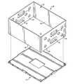
- FIG. 1is a top perspective view of an embodiment of a tray for the inventive box.
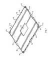
- FIG. 2is an exploded view of a sleeve for the inventive box in the process of being placed on the tray of FIG. 1 .
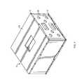
- FIG. 3is an assembled view of the sleeve and tray of FIG. 2 , illustrating the partially-assembled box ready to be filled with merchandise (such as bananas) that will be shipped in the box.
- merchandisesuch as bananas
- FIG. 4shows the box of FIG. 1-3 fully assembled, with a second tray covering the open top of the assembly of FIG. 3 ; the Figure does not shown the removable bands or other devices used to hold the trays and sleeve together after the box has been filled.
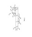
- FIG. 5is an enlarged side view of one corner of the tray of FIG. 1 , showing the post and barrier detail.
- FIG. 6is a top view of the die-cut blank used to make the sleeve shown in FIG. 2-4 (detailing relevant dimensions of the preferred embodiment in inches).
- FIG. 7is an enlarged view of the undersides of one corner of two of the preferred embodiment of the trays shown in FIGS. 1-5 , detailing the manner in which such trays nest for storage and shipment.
- One container or boxconsists of two identical, injected molded trays, and one corrugated plastic sleeve that folds flat to minimize the storage and shipping space required once the box is broken down into its three parts.
- the traysare lightweight and strong.
- the traysare nestable for condensed return freight efficiencies.
- theyinclude corner posts that help to align the corrugated plastic sleeve and locate the sleeve snugly on the tray.
- the corner postsinclude a tapered entry which transitions to a vertical 90-degree wall, which helps to lock the sleeve into position and pulls the sleeve sidewalls into a tight, rigid position for improved sleeve (container sidewall) stacking strength.
- the traysfurther include vertical projections or barriers projecting upward from each of the four edges of the tray. These barriers inhibit the sidewalls of the sleeve from expanding beyond the external perimeter of the tray.
- the barriersare preferably located centered on each of the four sides of the tray, at or close to the edges of the tray. The sleeve sits inside these barriers and rests up against them by the weight of the product pushing against the sleeve sidewalls.
- the trayshave ventilation holes in the center for two reasons: weight reduction and for cooling and gas applications when pallets are shipped in the holds of ships.
- the cooling gasescome up from the floor of the pallet.
- Weight control of the combined two trays and sleeveis important since a full truckload of bananas approaches the legal limit of weight a truck can safely carry. Any heavier than existing paper boxes, and shippers would have to leave product off the trucks which would affect the economics.
- the sleeveis preferably made from 5 mm corrugated polypropylene, but could be made from any malleable material such as corrugated paper, injection molded plastic or corrugated polyethylene.
- the advantages of corrugated plasticare that it is strong, lightweight and unaffected by moisture or humidity. Corrugated plastic's relative low cost and ability to be machined on specialized machinery, make it ideal for this application. Corrugated plastic can be mass produced at low cost to meet the volume requirements of a vast market. However, the sleeve could be made from any other existing or future material that has similar properties.
- the sleevepreferably has a desired quantity and size of ventilation holes cut out of the appropriate panels to provide airflow for cooling and ripening purposes in desired locations of the assembled box.
- the sleevealso preferably has two handholds at each end. The purpose of having two handholds is that the box is packed with the bananas crown up and stacked at the plantation with the bananas oriented in this position, meaning that they are shipped in this position. When the bananas leave the ripening rooms, many times the cases are inverted either individually or entire pallets at a time so the bananas are orientated crown down for consumer display; this prevents the need for supermarket personnel to invert each bunch of bananas. Having a mirror image handhold allows the box of bananas to be conveniently carried at both the plantation and at the store level.
- the radius on the cut out portion of the handholdis preferably included, as it helps reduce tearing associated with having a cut end on a vertical flute line.
- Reliefmay be cut into the length panel that marries to the glue flap so the sleeve can be put over the corner posts on the tray.
- the size of the sleeve and trayscan be easily modified to accommodate different case counts, products and other desirable variables.
- box or container 10is made up of two of trays 12 , and one sleeve 80 .
- Trays 12are preferably injection molded from a plastic material having the requisite strength and weight, but could be made of other materials such as metal.
- tray 12defines sides 38 - 41 .
- Projecting corner posts 14are located slightly inside of each corner on the top side 50 , at a distance from the edges that is approximately equal to the thickness of sleeve 80 .
- each post 14defines integral sections 16 and 18 , one located parallel to each of the edges, and having a length that is approximately related to the length of the side on which it resides; thus section 16 is longer than section 18 .
- Both of sections 16 and 18have an upper tapered wall portion 20 and a lower vertical wall portion 22 .
- Openings 70are located just inside of posts 14 and define an open area that is about the size of the area circumscribed by a post, so that the trays can be nested for storage and shipment, as shown in FIG. 7 .
- Trays 12further comprise four projecting walls or barrier portions 42 , one located at about the center of each side of the tray, at the edge.
- tray 12is about 16 by 20 inches, and posts 14 are about 0.50 inches high.
- Lower wall portion 22has a height of about 0.13 inches.
- Upper wall portion 20has a height of about 0.37 inches, and is tapered inward at a shallow angle.
- Barrier portions 42are about 0.38 inches high and about 4 inches long.
- Central opening 62is about 4 by 6 inches.
- the outer rim of the trayshas a thickness of about 0.31 inches, and feet 64 and 65 project below the rim by about 0.19 inches.
- Sleeve 80is preferably die cut from 5 mm thick corrugated polypropylene material, and defines handle cutouts 92 and openings 94 , both located on the short sides of the assembled sleeve and shown if FIG. 2 ; more or fewer openings and/or openings on other of the sleeve sidewalls can be used as desired.
- Assemblyis accomplished by gluing the end flaps together to create a joint area. As shown in FIG. 6 , the assembled sleeve can be folded flat along score lines 96 - 99 , as desired. When expanded, sleeve 80 defines open ends 82 and 83 that are sized and shaped to fit a tray 12 . When box 10 is assembled, trays 12 comprise the bottom and top, and sleeve 80 defines the box sidewalls.
- One or more strong removable straps of a type known in the artare used to keep box 10 fully assembled, once the product to be shipped and displayed has been placed into the box.
- Box 10is used as follows. As shown in FIG. 1 , a tray 10 is placed on a surface with top 50 facing up. As shown in FIGS. 2 and 3 , sleeve 80 is placed edge down on tray 12 such that the sleeve corners are located just outside of posts 14 , and the sleeve sidewalls are located just inside of barriers 42 . Upper tapered post portions 20 help to guide sleeve 80 into place as it is slipped over the posts, while lower vertical portions 22 help to hold sleeve 80 squared tightly in place. Barriers 42 help to prevent the sleeve sidewalls from bowing outward appreciably when product is placed into the open-top box.
- bananas or other product being shippedare placed into the container through open end 82 of sleeve 80 , which is the open top of the container. Bananas are placed in the normal shipping position—crown up.
- a second tray 12is placed upside down on the open top, with its bottom side 60 facing out, as shown in FIG. 4 .
- One or more straps or other releasable devices that hold the assembly togetherare then placed, and box 10 is ready to be shipped. Openings 62 and 94 allow for flow of cooling and ripening gases.
- box 10For retail display, box 10 is flipped over and placed on a display shelf. The straps are removed. Upper tray 12 and sleeve 80 are removed. This leaves lower tray 12 with product (e.g., bananas) sitting thereon. Store personnel do not need to lift the bananas from the box or turn them upward (crown down) for display. In fact, personnel do not need to handle the bananas in any way.
- producte.g., bananas
- the empty trayscan be stacked and placed on pallets for shipment back to the packing location.
- the sleevescan be folded flat, palletized, and returned for re-use.
Landscapes
- Engineering & Computer Science (AREA)
- Mechanical Engineering (AREA)
- Stackable Containers (AREA)
Abstract
Description
Claims (9)
Priority Applications (2)
| Application Number | Priority Date | Filing Date | Title |
|---|---|---|---|
| US12/640,246US8631956B2 (en) | 2008-12-17 | 2009-12-17 | Reusable, combined multi-part product shipping box and display tray |
| US14/158,361US20140263305A1 (en) | 2008-12-17 | 2014-01-17 | Multi-Part Product Shipping Box and Display Tray |
Applications Claiming Priority (2)
| Application Number | Priority Date | Filing Date | Title |
|---|---|---|---|
| US13822008P | 2008-12-17 | 2008-12-17 | |
| US12/640,246US8631956B2 (en) | 2008-12-17 | 2009-12-17 | Reusable, combined multi-part product shipping box and display tray |
Related Child Applications (1)
| Application Number | Title | Priority Date | Filing Date |
|---|---|---|---|
| US14/158,361Continuation-In-PartUS20140263305A1 (en) | 2008-12-17 | 2014-01-17 | Multi-Part Product Shipping Box and Display Tray |
Publications (2)
| Publication Number | Publication Date |
|---|---|
| US20100147840A1 US20100147840A1 (en) | 2010-06-17 |
| US8631956B2true US8631956B2 (en) | 2014-01-21 |
Family
ID=42239289
Family Applications (1)
| Application Number | Title | Priority Date | Filing Date |
|---|---|---|---|
| US12/640,246Active - Reinstated2031-04-29US8631956B2 (en) | 2008-12-17 | 2009-12-17 | Reusable, combined multi-part product shipping box and display tray |
Country Status (1)
| Country | Link |
|---|---|
| US (1) | US8631956B2 (en) |
Cited By (13)
| Publication number | Priority date | Publication date | Assignee | Title |
|---|---|---|---|---|
| US20140261533A1 (en)* | 2013-03-15 | 2014-09-18 | Barbara Brock | Compact Organizer for Cosmetics |
| US20180077944A1 (en)* | 2016-09-16 | 2018-03-22 | Christophe Obolo | Produce Ripening System and Method |
| US9986852B2 (en) | 2016-10-14 | 2018-06-05 | Stein Industries, Inc. | Product display systems |
| US10118727B2 (en) | 2016-09-15 | 2018-11-06 | Arena Packaging, Llc | Container having an access door latching system |
| US10130196B2 (en) | 2014-08-07 | 2018-11-20 | Artform International Limited | Product display shelf, system and method |
| RU186901U1 (en)* | 2017-11-27 | 2019-02-07 | ППО ГРУП ЦЗ. с.р.о. | COMBINED CONTAINER FOR TRANSPORTATION AND STORAGE OF GOODS |
| US10273052B2 (en) | 2015-12-23 | 2019-04-30 | Arena Packaging, Llc | Produce shipping container |
| US10405674B2 (en) | 2016-03-23 | 2019-09-10 | Retail Space Solutions Llc | Low product indicator for self facing merchandiser and related methods |
| US10702076B2 (en) | 2016-01-18 | 2020-07-07 | Atlas Bolt & Screw Company Llc | Sensors, devices, adapters and mating structures for merchandisers and related methods |
| US10849332B2 (en) | 2016-09-16 | 2020-12-01 | Christophe Obolo | Produce ripening system and apparatus |
| US10952548B2 (en) | 2016-10-18 | 2021-03-23 | Retail Space Solutions Llc | Illuminated merchandiser, retrofit kit and related methods |
| US20230182969A1 (en)* | 2021-12-15 | 2023-06-15 | Technology Container Corp. | Container for the shipment and display of a product |
| US11866225B2 (en) | 2021-03-01 | 2024-01-09 | Fives Intralogistics Corp. | Reusable knock-down shipping container |
Families Citing this family (18)
| Publication number | Priority date | Publication date | Assignee | Title |
|---|---|---|---|---|
| US8864017B2 (en) | 2011-10-13 | 2014-10-21 | Orbis Corporation | Plastic corrugated container with improved fold lines and method and apparatus for making same |
| DE102011055019B4 (en) | 2011-11-03 | 2020-07-30 | Schoeller Arca Systems Gmbh | Transport and presentation containers |
| US20160039598A1 (en)* | 2013-04-22 | 2016-02-11 | A.R. Arena Products, Inc. | Reusable plastic container for shipping of produce |
| US10625916B2 (en) | 2013-12-24 | 2020-04-21 | Orbis Corporation | Plastic corrugated container with soft score line |
| US11643242B2 (en) | 2013-12-24 | 2023-05-09 | Orbis Corporation | Air vent for welded portion in plastic corrugated material, and process for forming welded portion |
| US10829265B2 (en) | 2013-12-24 | 2020-11-10 | Orbis Corporation | Straight consistent body scores on plastic corrugated boxes and a process for making same |
| EP3865415B1 (en) | 2013-12-24 | 2024-07-17 | Orbis Corporation | Manufacturing process of a blank for forming a plastic corrugated container |
| DE102015100886A1 (en) | 2015-01-22 | 2016-07-28 | Ifco Systems Gmbh | display container |
| CN104812218B (en)* | 2015-04-30 | 2017-03-22 | 昆山荣科钣金科技有限公司 | High-heat-dissipation control box and production method |
| EP3585693B1 (en) | 2017-02-21 | 2023-09-20 | Orbis Corporation | Plastic corrugated boxes with scored fold lines |
| US11072140B2 (en) | 2017-06-20 | 2021-07-27 | Orbis Corporation | Balanced process for extrusion of plastic corrugated sheet and subsequent converting into plastic boxes |
| US10934051B1 (en) | 2019-08-08 | 2021-03-02 | International Business Machines Corporation | Self-activated container |
| US11226369B2 (en) | 2019-09-26 | 2022-01-18 | International Business Machines Corporation | Ball grid array current meter with a current sense loop |
| US11519957B2 (en) | 2019-09-26 | 2022-12-06 | International Business Machines Corporation | Ball grid array current meter with a current sense wire |
| US11054442B2 (en) | 2019-09-26 | 2021-07-06 | International Business Machines Corporation | Ball grid array current meter with a current sense mesh |
| MX2022013891A (en)* | 2021-03-11 | 2023-04-05 | Varillas Sergio Fernando Grijalva | Packaging for fruit and vegetables with antipathogen barrier and production method. |
| CN115223445B (en)* | 2021-04-21 | 2023-12-12 | 鸿富锦精密工业(武汉)有限公司 | Monitor and its packaging box |
| US20250197082A1 (en)* | 2023-12-15 | 2025-06-19 | Somos Entelequia, Sa. De C.V. | Air flow control system for packaging |
Citations (10)
| Publication number | Priority date | Publication date | Assignee | Title |
|---|---|---|---|---|
| US3986659A (en)* | 1975-01-27 | 1976-10-19 | Leslie Vajtay | End caps for tubular containers |
| US4782972A (en)* | 1986-06-30 | 1988-11-08 | Traex Corporation | Collapsible file box |
| US4785957A (en)* | 1987-08-19 | 1988-11-22 | Beck James R | Collapsible shipping container |
| US5332088A (en) | 1991-12-19 | 1994-07-26 | Schreiber Harry A | Fruit display box with hand holes |
| US5829595A (en)* | 1997-03-03 | 1998-11-03 | Trienda Corporation | Thin sheet thermoformed pallet sleeve |
| US6024223A (en)* | 1999-02-04 | 2000-02-15 | Technology Container Corporation | Storage container including a mounting clip an associated mounting clip, and an associated method |
| US6257484B1 (en) | 1999-03-17 | 2001-07-10 | Technology Container Corporation | Collapsible corrugated plastic box having tear-resistant hand holds |
| US6705515B2 (en) | 2002-06-20 | 2004-03-16 | Technology Container Corp. | Self erecting and collapsible corrugated plastic box |
| US6926192B1 (en) | 2003-11-10 | 2005-08-09 | Technology Container Corporation | Collapsible movie film box with automatic locking bottom |
| US20070272699A1 (en)* | 2004-01-27 | 2007-11-29 | Francois Girault | Folding Rectangular Parallelepiped Box |
- 2009
- 2009-12-17USUS12/640,246patent/US8631956B2/enactiveActive - Reinstated
Patent Citations (10)
| Publication number | Priority date | Publication date | Assignee | Title |
|---|---|---|---|---|
| US3986659A (en)* | 1975-01-27 | 1976-10-19 | Leslie Vajtay | End caps for tubular containers |
| US4782972A (en)* | 1986-06-30 | 1988-11-08 | Traex Corporation | Collapsible file box |
| US4785957A (en)* | 1987-08-19 | 1988-11-22 | Beck James R | Collapsible shipping container |
| US5332088A (en) | 1991-12-19 | 1994-07-26 | Schreiber Harry A | Fruit display box with hand holes |
| US5829595A (en)* | 1997-03-03 | 1998-11-03 | Trienda Corporation | Thin sheet thermoformed pallet sleeve |
| US6024223A (en)* | 1999-02-04 | 2000-02-15 | Technology Container Corporation | Storage container including a mounting clip an associated mounting clip, and an associated method |
| US6257484B1 (en) | 1999-03-17 | 2001-07-10 | Technology Container Corporation | Collapsible corrugated plastic box having tear-resistant hand holds |
| US6705515B2 (en) | 2002-06-20 | 2004-03-16 | Technology Container Corp. | Self erecting and collapsible corrugated plastic box |
| US6926192B1 (en) | 2003-11-10 | 2005-08-09 | Technology Container Corporation | Collapsible movie film box with automatic locking bottom |
| US20070272699A1 (en)* | 2004-01-27 | 2007-11-29 | Francois Girault | Folding Rectangular Parallelepiped Box |
Cited By (18)
| Publication number | Priority date | Publication date | Assignee | Title |
|---|---|---|---|---|
| US9332814B2 (en)* | 2013-03-15 | 2016-05-10 | Barbara Brock | Compact organizer for cosmetics |
| US20140261533A1 (en)* | 2013-03-15 | 2014-09-18 | Barbara Brock | Compact Organizer for Cosmetics |
| US10470594B2 (en) | 2014-08-07 | 2019-11-12 | Artform International Limited | Product display shelf, system and method |
| US10130196B2 (en) | 2014-08-07 | 2018-11-20 | Artform International Limited | Product display shelf, system and method |
| US10273052B2 (en) | 2015-12-23 | 2019-04-30 | Arena Packaging, Llc | Produce shipping container |
| US10702076B2 (en) | 2016-01-18 | 2020-07-07 | Atlas Bolt & Screw Company Llc | Sensors, devices, adapters and mating structures for merchandisers and related methods |
| US10405674B2 (en) | 2016-03-23 | 2019-09-10 | Retail Space Solutions Llc | Low product indicator for self facing merchandiser and related methods |
| US10588427B2 (en) | 2016-03-23 | 2020-03-17 | Retail Space Solutions Llc | Low product indicator for self facing merchandiser and related methods |
| US11291312B2 (en) | 2016-03-23 | 2022-04-05 | Retail Space Solutions Llc | Low product indicator for self facing merchandiser and related methods |
| US10118727B2 (en) | 2016-09-15 | 2018-11-06 | Arena Packaging, Llc | Container having an access door latching system |
| US20180077944A1 (en)* | 2016-09-16 | 2018-03-22 | Christophe Obolo | Produce Ripening System and Method |
| US10849332B2 (en) | 2016-09-16 | 2020-12-01 | Christophe Obolo | Produce ripening system and apparatus |
| US10441093B2 (en) | 2016-10-14 | 2019-10-15 | Stein Industries, Inc. | Detachable lighting housing with lighting unit for product display systems |
| US9986852B2 (en) | 2016-10-14 | 2018-06-05 | Stein Industries, Inc. | Product display systems |
| US10952548B2 (en) | 2016-10-18 | 2021-03-23 | Retail Space Solutions Llc | Illuminated merchandiser, retrofit kit and related methods |
| RU186901U1 (en)* | 2017-11-27 | 2019-02-07 | ППО ГРУП ЦЗ. с.р.о. | COMBINED CONTAINER FOR TRANSPORTATION AND STORAGE OF GOODS |
| US11866225B2 (en) | 2021-03-01 | 2024-01-09 | Fives Intralogistics Corp. | Reusable knock-down shipping container |
| US20230182969A1 (en)* | 2021-12-15 | 2023-06-15 | Technology Container Corp. | Container for the shipment and display of a product |
Also Published As
| Publication number | Publication date |
|---|---|
| US20100147840A1 (en) | 2010-06-17 |
Similar Documents
| Publication | Publication Date | Title |
|---|---|---|
| US8631956B2 (en) | Reusable, combined multi-part product shipping box and display tray | |
| US5752602A (en) | Stackable and nestable one part container | |
| US4709852A (en) | Produce transport and cooling container and method for using same | |
| US6948617B2 (en) | Stackable container with support flanges | |
| US5263612A (en) | Fibreboard container for fresh produce | |
| US6405921B1 (en) | Perforated carton and product display system | |
| US7637372B2 (en) | Hybrid shoppable pallet display | |
| US5540536A (en) | Reusable packaging, shipping and display system | |
| CA2390899C (en) | Economical, stackable container for retail goods | |
| US3552633A (en) | Pallet case | |
| EP3184459B1 (en) | Shipping container convertible into a display configuration | |
| US8439187B2 (en) | Shipping and display container with removable panel | |
| US5195677A (en) | Hood and tray carton and blanks for forming same | |
| US11383878B2 (en) | Box container and display | |
| US6286753B1 (en) | Displayable produce container and method for making the same | |
| US6488200B1 (en) | Multi-function crate-tray and display | |
| US4825624A (en) | Modular promotional display | |
| US20140263305A1 (en) | Multi-Part Product Shipping Box and Display Tray | |
| US20130126373A1 (en) | Shipping system for plants or other items | |
| US2718996A (en) | Container and closure therefor | |
| US9205947B1 (en) | Multi-component container with air cell end panel reinforcements | |
| US20030052038A1 (en) | Corrugated container with integral pallet | |
| US3208079A (en) | Shipping container | |
| US20080000955A1 (en) | Filler tray and unitary blank for assembling same | |
| US20040104138A1 (en) | Large-capacity shipment and display bin |
Legal Events
| Date | Code | Title | Description |
|---|---|---|---|
| FEPP | Fee payment procedure | Free format text:MAINTENANCE FEE REMINDER MAILED (ORIGINAL EVENT CODE: REM.) | |
| LAPS | Lapse for failure to pay maintenance fees | Free format text:PATENT EXPIRED FOR FAILURE TO PAY MAINTENANCE FEES (ORIGINAL EVENT CODE: EXP.) | |
| FP | Lapsed due to failure to pay maintenance fee | Effective date:20180121 | |
| PRDP | Patent reinstated due to the acceptance of a late maintenance fee | Effective date:20180531 | |
| FEPP | Fee payment procedure | Free format text:SURCHARGE, PETITION TO ACCEPT PYMT AFTER EXP, UNINTENTIONAL. (ORIGINAL EVENT CODE: M2558); ENTITY STATUS OF PATENT OWNER: SMALL ENTITY Free format text:PETITION RELATED TO MAINTENANCE FEES GRANTED (ORIGINAL EVENT CODE: PMFG) Free format text:PETITION RELATED TO MAINTENANCE FEES FILED (ORIGINAL EVENT CODE: PMFP) | |
| MAFP | Maintenance fee payment | Free format text:PAYMENT OF MAINTENANCE FEE, 4TH YR, SMALL ENTITY (ORIGINAL EVENT CODE: M2551) Year of fee payment:4 | |
| STCF | Information on status: patent grant | Free format text:PATENTED CASE | |
| AS | Assignment | Owner name:INTERSTATE CONTAINER LOWELL LLC, MASSACHUSETTS Free format text:ASSIGNMENT OF ASSIGNORS INTEREST;ASSIGNOR:DOWD, FRED;REEL/FRAME:054211/0702 Effective date:20201029 | |
| MAFP | Maintenance fee payment | Free format text:PAYMENT OF MAINTENANCE FEE, 8TH YR, SMALL ENTITY (ORIGINAL EVENT CODE: M2552); ENTITY STATUS OF PATENT OWNER: SMALL ENTITY Year of fee payment:8 | |
| MAFP | Maintenance fee payment | Free format text:PAYMENT OF MAINTENANCE FEE, 12TH YR, SMALL ENTITY (ORIGINAL EVENT CODE: M2553); ENTITY STATUS OF PATENT OWNER: SMALL ENTITY Year of fee payment:12 |