US8631827B2 - Fluid flow control device - Google Patents
Fluid flow control deviceDownload PDFInfo
- Publication number
- US8631827B2 US8631827B2US12/862,637US86263710AUS8631827B2US 8631827 B2US8631827 B2US 8631827B2US 86263710 AUS86263710 AUS 86263710AUS 8631827 B2US8631827 B2US 8631827B2
- Authority
- US
- United States
- Prior art keywords
- fluid
- fluid flow
- control apparatus
- flow control
- internal surface
- Prior art date
- Legal status (The legal status is an assumption and is not a legal conclusion. Google has not performed a legal analysis and makes no representation as to the accuracy of the status listed.)
- Expired - Lifetime, expires
Links
Images


Classifications
- F—MECHANICAL ENGINEERING; LIGHTING; HEATING; WEAPONS; BLASTING
- F04—POSITIVE - DISPLACEMENT MACHINES FOR LIQUIDS; PUMPS FOR LIQUIDS OR ELASTIC FLUIDS
- F04F—PUMPING OF FLUID BY DIRECT CONTACT OF ANOTHER FLUID OR BY USING INERTIA OF FLUID TO BE PUMPED; SIPHONS
- F04F5/00—Jet pumps, i.e. devices in which flow is induced by pressure drop caused by velocity of another fluid flow
- F04F5/02—Jet pumps, i.e. devices in which flow is induced by pressure drop caused by velocity of another fluid flow the inducing fluid being liquid
- F04F5/04—Jet pumps, i.e. devices in which flow is induced by pressure drop caused by velocity of another fluid flow the inducing fluid being liquid displacing elastic fluids
- F04F5/06—Jet pumps, i.e. devices in which flow is induced by pressure drop caused by velocity of another fluid flow the inducing fluid being liquid displacing elastic fluids of rotary type
- F—MECHANICAL ENGINEERING; LIGHTING; HEATING; WEAPONS; BLASTING
- F16—ENGINEERING ELEMENTS AND UNITS; GENERAL MEASURES FOR PRODUCING AND MAINTAINING EFFECTIVE FUNCTIONING OF MACHINES OR INSTALLATIONS; THERMAL INSULATION IN GENERAL
- F16L—PIPES; JOINTS OR FITTINGS FOR PIPES; SUPPORTS FOR PIPES, CABLES OR PROTECTIVE TUBING; MEANS FOR THERMAL INSULATION IN GENERAL
- F16L55/00—Devices or appurtenances for use in, or in connection with, pipes or pipe systems
- F16L55/02—Energy absorbers; Noise absorbers
- F16L55/027—Throttle passages
- B—PERFORMING OPERATIONS; TRANSPORTING
- B05—SPRAYING OR ATOMISING IN GENERAL; APPLYING FLUENT MATERIALS TO SURFACES, IN GENERAL
- B05B—SPRAYING APPARATUS; ATOMISING APPARATUS; NOZZLES
- B05B1/00—Nozzles, spray heads or other outlets, with or without auxiliary devices such as valves, heating means
- B05B1/34—Nozzles, spray heads or other outlets, with or without auxiliary devices such as valves, heating means designed to influence the nature of flow of the liquid or other fluent material, e.g. to produce swirl
- B05B1/3405—Nozzles, spray heads or other outlets, with or without auxiliary devices such as valves, heating means designed to influence the nature of flow of the liquid or other fluent material, e.g. to produce swirl to produce swirl
- B05B1/341—Nozzles, spray heads or other outlets, with or without auxiliary devices such as valves, heating means designed to influence the nature of flow of the liquid or other fluent material, e.g. to produce swirl to produce swirl before discharging the liquid or other fluent material, e.g. in a swirl chamber upstream the spray outlet
- F—MECHANICAL ENGINEERING; LIGHTING; HEATING; WEAPONS; BLASTING
- F15—FLUID-PRESSURE ACTUATORS; HYDRAULICS OR PNEUMATICS IN GENERAL
- F15D—FLUID DYNAMICS, i.e. METHODS OR MEANS FOR INFLUENCING THE FLOW OF GASES OR LIQUIDS
- F15D1/00—Influencing flow of fluids
- F15D1/02—Influencing flow of fluids in pipes or conduits
- F15D1/04—Arrangements of guide vanes in pipe elbows or duct bends; Construction of pipe conduit elements for elbows with respect to flow, e.g. for reducing losses of flow
- F—MECHANICAL ENGINEERING; LIGHTING; HEATING; WEAPONS; BLASTING
- F16—ENGINEERING ELEMENTS AND UNITS; GENERAL MEASURES FOR PRODUCING AND MAINTAINING EFFECTIVE FUNCTIONING OF MACHINES OR INSTALLATIONS; THERMAL INSULATION IN GENERAL
- F16L—PIPES; JOINTS OR FITTINGS FOR PIPES; SUPPORTS FOR PIPES, CABLES OR PROTECTIVE TUBING; MEANS FOR THERMAL INSULATION IN GENERAL
- F16L9/00—Rigid pipes
- F—MECHANICAL ENGINEERING; LIGHTING; HEATING; WEAPONS; BLASTING
- F24—HEATING; RANGES; VENTILATING
- F24F—AIR-CONDITIONING; AIR-HUMIDIFICATION; VENTILATION; USE OF AIR CURRENTS FOR SCREENING
- F24F5/00—Air-conditioning systems or apparatus not covered by F24F1/00 or F24F3/00, e.g. using solar heat or combined with household units such as an oven or water heater
- G—PHYSICS
- G05—CONTROLLING; REGULATING
- G05D—SYSTEMS FOR CONTROLLING OR REGULATING NON-ELECTRIC VARIABLES
- G05D7/00—Control of flow
- G05D7/01—Control of flow without auxiliary power
- G05D7/0186—Control of flow without auxiliary power without moving parts
- Y—GENERAL TAGGING OF NEW TECHNOLOGICAL DEVELOPMENTS; GENERAL TAGGING OF CROSS-SECTIONAL TECHNOLOGIES SPANNING OVER SEVERAL SECTIONS OF THE IPC; TECHNICAL SUBJECTS COVERED BY FORMER USPC CROSS-REFERENCE ART COLLECTIONS [XRACs] AND DIGESTS
- Y10—TECHNICAL SUBJECTS COVERED BY FORMER USPC
- Y10T—TECHNICAL SUBJECTS COVERED BY FORMER US CLASSIFICATION
- Y10T137/00—Fluid handling
- Y10T137/0318—Processes
- Y—GENERAL TAGGING OF NEW TECHNOLOGICAL DEVELOPMENTS; GENERAL TAGGING OF CROSS-SECTIONAL TECHNOLOGIES SPANNING OVER SEVERAL SECTIONS OF THE IPC; TECHNICAL SUBJECTS COVERED BY FORMER USPC CROSS-REFERENCE ART COLLECTIONS [XRACs] AND DIGESTS
- Y10—TECHNICAL SUBJECTS COVERED BY FORMER USPC
- Y10T—TECHNICAL SUBJECTS COVERED BY FORMER US CLASSIFICATION
- Y10T137/00—Fluid handling
- Y10T137/206—Flow affected by fluid contact, energy field or coanda effect [e.g., pure fluid device or system]
- Y10T137/2087—Means to cause rotational flow of fluid [e.g., vortex generator]
Definitions
- the present inventionrelates to nozzles, diffusers and venturis. It may be applied in any application in which nozzles, diffusers and venturis are used.
- Nozzles, diffusers and venturisare specific types of ducts used in relation to the flow of fluid.
- a nozzleis intended to mean a duct of varying cross-sectional area which is designed so that fluid flow is accelerated by a pressure differentiated between the inlet and the outlet.
- a diffuseris intended to mean a duct of varying cross-sectional area which is designed so that fluid flow is decelerated by an increase of pressure between the inlet and the outlet.
- a venturican be seen as a duct comprising a nozzle section and diffuser section abutted in tandem.
- Nozzlesare widely used in the field of fluid flow as a means to provide an accelerated stream of fluid and have many applications.
- Diffusersare used to decelerate fluid flow and again have many applications.
- Venturisare used to cause a short region of accelerated flow in a duct. It is a well known law of thermodynamics that the accelerated fluid flow is accompanied by a reduced pressure, and that many applications of venturis are directed to utilising the reduced pressure.
- an exemplary embodiment of the present inventionprovides a flow controller adapted to control a flow of fluid within the controller, the flow controller having a flow path adapted to convey said fluid, wherein the cross-sectional area of the flow path varies along the flow path and wherein in at least a portion of its length the flow controller comprises an active surface capable of influencing the fluid flow through the flow path.
- the active surfaceis adapted to cause rotational motion of fluid within the fluid pathway about the axis of flow of the fluid.
- the active surfaceis adapted to cause vortical motion of fluid within the fluid pathway about the axis of flow of the fluid.
- the configuration of the active surfaceconforms to at least one logarithmic curve conforming to the Golden Section.
- the curvature of the active surfaceis uni-dimensional.
- the curvature of the active surfaceis bi-dimensional.
- the curvature of the active surfacevaries in accordance with the Golden Section.
- the curvature of the active surfaceconforms to an equiangular spiral.
- the curvature of the active surfaceis transverse to the central axis of the fluid pathway.
- the curvature of the active surfacecan be in a direction parallel to the central axis.
- the curvature of the active surfaceis both transverse to the central axis and is parallel to the direction of the central axis to define a three-dimensional surface conforming substantially or in the greater part to the Golden Section.
- the fluid pathwayhas a spiral configuration.
- the configurationtakes the form of a logarithmic helix or a volute or a whorl.
- the cross-sectional area of the flow pathvaries logarithmically substantially or in greater part in conformity to the Golden Section.
- the cross-sectional area of the flow pathvaries to cause the incremental volume of the flow path to vary logarithmically.
- the incremental volumeis caused to vary in conformity with the Golden Ratio.
- the active surfacehas the configuration conforming to the external configuration of a shell of the phylum Mollusca, class Gastropoda or Cephalopoda.
- the active surfaceconforms to the external configuration of shells selected from the genera Volutidea, Argonauta, Nautilus, Conidea or Turbinidea.
- the active surfacehas the configuration of the interior of shells of the phylum Mollusca; classes Gastropoda or Cephalopoda.
- the active surfacehas the configuration of the interior of shells selected from the genera Volutidea, Conidea, Turbinidea, Argonauta, or Nautilus.
- the configuration of the flow controllerpromotes substantially radially laminar fluid flow.
- the flow controllercomprises a nozzle.
- the flow controllercomprises a diffuser.
- the flow controllercomprises a venturi.
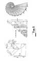
- FIG. 1is a chart of the Golden Section or Fibonacci Progression
- FIG. 2is an isometric view of a nozzle according to a first embodiment
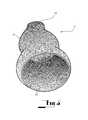
- FIG. 3is an isometric view of a nozzle according to a second embodiment
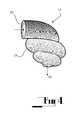
- FIG. 4is an isometric view of a nozzle according to a third embodiment
- FIG. 5is an isometric view of a diffuser according to a fourth embodiment
- FIG. 6is a sectional elevation of a conventional venturi tube
- FIG. 7is an isometric view of a venturi according to a fifth embodiment
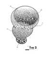
- FIG. 8is an isometric view of a venturi according to a sixth embodiment.
- An embodiment of the inventionis directed to a flow controller, the structure of which is configured to cause the rate of a fluid flow to be altered during passage through the controller.
- Each of the embodimentsis directed to a flow controller adapted to alter the rate of flow of a fluid.
- Each of the embodimentsserves, in the greater part, to enable fluids to move in their naturally preferred way, thereby reducing inefficiencies created through turbulence and friction which are normally found in apparatus commonly used for propagating fluid flow.
- Previously developed technologieshave generally been less compliant with natural fluid flow tendencies.
- the greater percentage of the surfaces of the flow controller of each of the embodiments described hereinare generally designed in the greater part, in accordance with the Golden Section or Ratio or are designed to ensure the volume of fluid flowing through the flow controller expands or contracts in the greater part in accordance with the Golden Section and therefore it is a characteristic of each of the embodiments that the flow controller provides a fluid pathway which is of a spiralling configuration and which conforms at least in greater part to the characteristics of the Golden Section or Ratio.
- FIG. 1illustrates the unfolding of the spiral curve according to the Golden Section or Ratio.
- the order of growth of the radius of the curve which is measured at equiangular radiie.g., E, F, G, H, I and J
- equiangular radiie.g., E, F, G, H, I and J
- This can be illustrated from the triangular representation of each radius between each sequence which corresponds to the formula of a:bb:a+b which conforms to the ratio of 1:0.618 approximately and which is consistent throughout the curve.
- the curvature of the surfaces which form the flow controllertakes a two dimensional or three dimensional shape equivalent to the lines of vorticity or streak lines found in a naturally occurring vortex.
- the curvature of the surfacessubstantially or in the greater part conform to the characteristics of the Golden Section or Ratio and that any variation in cross-sectional area of the flow controller also substantially or in greater part conforms to the characteristics of the Golden Section or Ratio.
- the curvature of the active surfaceconforms to an equiangular spiral.
- the characteristics of the Golden Section or Ratioare found in nature in the form of the external and internal configurations of shells of the phylum Mollusca, classes Gastropoda and Cephalopoda and it is a common characteristic of at least some of the embodiments that the fluid pathway defined by the flow controller corresponds generally to the external or internal configuration of shells of one or more of the genera of the phylum Mollusca, classes Gastropoda and Cephalopoda.
- the outer surfaces of the embodiments in the drawingsare depicted in a way whereby they would correspond with the inner surfaces, such as would be the case if the walls of the embodiments are of constant thickness. In this way some concept of the helical/spiral configurations of the inner surfaces is conveyed.
- the configuration of the outer surfaceis not of significance to the embodiments and thus the outer surface could be configured as a simple surface such as a cone., leaving the inner surface complex as suggested in these drawings.
- the first embodimenttakes the form of a nozzle as shown in FIG. 2 .
- the nozzle 11has a nozzle body 21 , an outlet 22 and an inlet 23 which is adapted to be joined to a duct (not shown) such as a pipe, hose or similar providing a source of fluid under pressure.
- the nozzle body 21has an internal surface 25 which reduces in cross-sectional area to the outlet 22 .
- the internal surface of the nozzlemay be seen to twist in a combination helical manner and spiralling manner between the input and the output. As indicated above, this twist is in a configuration which provides an active surface which conforms at least in greater part to the characteristics of the Golden Section or Ratio. It will be seen that as a result of the twist, fluid flowing in the nozzle is caused to be given a rotational motion about the longitudinal axis of the nozzle to thereby induce vortical motion in the fluid.
- a second embodimenttakes the form of a nozzle as shown in FIG. 3 .
- the second embodimentis of substantially similar construction to that of the first embodiment, and therefore in the drawings like parts are denoted with like numerals.
- the second embodimentdiffers from the first only in the particular design of the nozzle in that it is relatively longer and has greater twist.
- the formation of the vortical flow emitted from the nozzle outletcan be controlled. In certain applications, it will be desirable for the outlet to comprise a narrow vortical stream while in others, a diverging stream will be required to promote mixing of the output with the surrounding fluid.
- a third embodimenttakes the form of a nozzle as shown in FIG. 4 .
- the twist in the flow surfacescauses the direction of flow to be diverted transversely to that of the incoming flow stream. This redirection is achieved without significant loss because the internal surface of the nozzle is still configured to conform at least in greater part to the characteristics of the Golden Section or Ratio. As a result, turbulence is substantially avoided.
- a fourth embodimenttakes the form of a diffuser as shown in FIG. 5 .
- a diffusermay comprise a flow controller substantially identical to a nozzle but with direction of flow reversed.
- the diffuser of FIG. 5corresponds with the nozzle of FIG. 2 but having an internal surface 25 which increases in cross-sectional area to the outlet 22 . Therefore, in the drawings like numerals are again used to depict like features.
- the precise characteristics of the output flowcan be controlled by varying the design properties of the diffuser while maintaining the inner surface to conform at least in greater part to the characteristics of the Golden Section or Ratio.
- the cross-sectional area of the previous embodimentsvaries between the inlets to the outlets; for the nozzles, the area decreasing and for the diffusers, the area increasing.
- further embodiments of the fluid flow control devices as previously describedare configured to conform with this constraint. As a result, the volume of fluid flowing through the flow controller expands or contracts in the greater part in accordance with the Golden Ratio.
- a fifth embodimenttakes the form of a modified venturi tube as shown in FIG. 7 .
- the modified venturi tubeis best appreciated by comparison with a conventional venturi tube which is depicted In FIG. 6 .
- a venturi 51comprises an inlet 52 , an outlet 53 and a constricted region 54 .
- the constricted region 54comprises an entry 55 , an exit 56 and a region of maximum constriction 57 .
- the flowis represented by flow lines 58 .
- the modified venturi 61comprises an inlet 62 , an outlet 63 , a region of maximum constriction 64 , an entry 65 and an exit 66 . It will be readily perceived that these portions conform generally to corresponding portions of the conventional venturi tube of FIG. 6 .
- the entry 64 and exit 65are specifically designed to induce the fluid to move in accordance with the laws of Nature.
- the flow controlleris designed with a pathway having a curvature substantially or in greater part conforming to that of the Golden Section or Ratio. The fluid is thereby induced into vortical flow the greater part of which conforms to the Golden Section or Ratio. The energy losses caused as a result of this vortical flow are considerably lower than those which result from a conventional venturi.
- the apparatusmay be used more effectively than previously has been possible. Firstly, it is possible to increase the ratio of the area of inlet relative to the area of maximum constriction. This increases the relative pressure difference that may be generated between the inlet and the region of maximum constriction. This broadens the scope of use of the device.
- a sixth embodimenttakes the form of a modified venturi tube as shown in FIG. 8 .
- the sixth embodimentalthough somewhat different in appearance, operates in substantially the same manner as that of fifth embodiment and so, in the drawings, like parts are denoted with like numerals.
- the sixth embodimentagain comprises a duct, the area of cross-section of which reduces from an inlet to a portion of maximum constriction, and then increase to the outlet.
- the difference between the sixth embodiment and the fifthis that in the fifth embodiment the flow induces a vortex which has an axis of rotation which is co-linearly aligned with the central axis of the inlet, whereas in the sixth embodiment, the axis of rotation of the vortex is disposed substantially transversely to the central the axis of the inlet.
- the cross-sectional area of the ductvaries along the flow path, decreasing in the entry and increasing in the exit.
- further embodiments of the modified venturi tubes as previously describedare configured to conform with this constraint. As a result, the volume of fluid flowing through the entry and exit of the venturi contracts or expands in the greater part in accordance with the Golden Ratio.
- the arrangementspromote substantially radial laminar flow and it is believed that this assists the efficiency of the fluid flow within those arrangements
Landscapes
- Engineering & Computer Science (AREA)
- General Engineering & Computer Science (AREA)
- Mechanical Engineering (AREA)
- Physics & Mathematics (AREA)
- Fluid Mechanics (AREA)
- Automation & Control Theory (AREA)
- General Physics & Mathematics (AREA)
- Life Sciences & Earth Sciences (AREA)
- Sustainable Development (AREA)
- Chemical & Material Sciences (AREA)
- Combustion & Propulsion (AREA)
- Pipe Accessories (AREA)
- Jet Pumps And Other Pumps (AREA)
- Nozzles (AREA)
- Flow Control (AREA)
Abstract
Description
Claims (21)
Priority Applications (2)
| Application Number | Priority Date | Filing Date | Title |
|---|---|---|---|
| US12/862,637US8631827B2 (en) | 2003-07-02 | 2010-08-24 | Fluid flow control device |
| US14/103,593US20140096854A1 (en) | 2003-07-02 | 2013-12-11 | Fluid flow control device |
Applications Claiming Priority (5)
| Application Number | Priority Date | Filing Date | Title |
|---|---|---|---|
| AU2003903386AAU2003903386A0 (en) | 2003-07-02 | 2003-07-02 | Fluid flow control device |
| AU2003903386 | 2003-07-02 | ||
| PCT/AU2004/000862WO2005003616A1 (en) | 2003-07-02 | 2004-06-29 | Fluid flow control device |
| US11/323,137US7802583B2 (en) | 2003-07-02 | 2005-12-29 | Fluid flow control device |
| US12/862,637US8631827B2 (en) | 2003-07-02 | 2010-08-24 | Fluid flow control device |
Related Parent Applications (1)
| Application Number | Title | Priority Date | Filing Date |
|---|---|---|---|
| US11/323,137ContinuationUS7802583B2 (en) | 2003-07-02 | 2005-12-29 | Fluid flow control device |
Related Child Applications (1)
| Application Number | Title | Priority Date | Filing Date |
|---|---|---|---|
| US14/103,593ContinuationUS20140096854A1 (en) | 2003-07-02 | 2013-12-11 | Fluid flow control device |
Publications (2)
| Publication Number | Publication Date |
|---|---|
| US20100313982A1 US20100313982A1 (en) | 2010-12-16 |
| US8631827B2true US8631827B2 (en) | 2014-01-21 |
Family
ID=31983020
Family Applications (3)
| Application Number | Title | Priority Date | Filing Date |
|---|---|---|---|
| US11/323,137Expired - Fee RelatedUS7802583B2 (en) | 2003-07-02 | 2005-12-29 | Fluid flow control device |
| US12/862,637Expired - LifetimeUS8631827B2 (en) | 2003-07-02 | 2010-08-24 | Fluid flow control device |
| US14/103,593AbandonedUS20140096854A1 (en) | 2003-07-02 | 2013-12-11 | Fluid flow control device |
Family Applications Before (1)
| Application Number | Title | Priority Date | Filing Date |
|---|---|---|---|
| US11/323,137Expired - Fee RelatedUS7802583B2 (en) | 2003-07-02 | 2005-12-29 | Fluid flow control device |
Family Applications After (1)
| Application Number | Title | Priority Date | Filing Date |
|---|---|---|---|
| US14/103,593AbandonedUS20140096854A1 (en) | 2003-07-02 | 2013-12-11 | Fluid flow control device |
Country Status (11)
| Country | Link |
|---|---|
| US (3) | US7802583B2 (en) |
| EP (1) | EP1644657A4 (en) |
| JP (1) | JP2007538201A (en) |
| KR (1) | KR20060037285A (en) |
| CN (1) | CN1816713A (en) |
| AU (1) | AU2003903386A0 (en) |
| CA (1) | CA2532090A1 (en) |
| EA (1) | EA007421B1 (en) |
| IL (1) | IL172815A (en) |
| MX (1) | MXPA06000145A (en) |
| WO (1) | WO2005003616A1 (en) |
Cited By (2)
| Publication number | Priority date | Publication date | Assignee | Title |
|---|---|---|---|---|
| US20130048086A1 (en)* | 2011-08-22 | 2013-02-28 | Robert Krause | Midpoint reversed directionally coupled double chamber structure for the natural induction of a tornado |
| US8733497B2 (en) | 2002-01-03 | 2014-05-27 | Pax Scientific, Inc. | Fluid flow controller |
Families Citing this family (33)
| Publication number | Priority date | Publication date | Assignee | Title |
|---|---|---|---|---|
| EP1470338A4 (en)* | 2002-01-03 | 2012-01-11 | Pax Scient Inc | Vortex ring generator |
| AUPR982502A0 (en)* | 2002-01-03 | 2002-01-31 | Pax Fluid Systems Inc. | A heat exchanger |
| US6845523B2 (en)* | 2002-08-16 | 2005-01-25 | Roger M. Copp | Rescue vest with rollers |
| AU2003903386A0 (en)* | 2003-07-02 | 2003-07-17 | Pax Scientific, Inc | Fluid flow control device |
| CA2544516C (en) | 2003-11-04 | 2014-04-29 | Pax Scientific, Inc. | Fluid circulation system |
| JP4695097B2 (en)* | 2004-01-30 | 2011-06-08 | パックス サイエンティフィック インコーポレイテッド | Centrifugal fan, pump or turbine housing |
| CN1985093A (en)* | 2004-01-30 | 2007-06-20 | 百思科技公司 | Housing for a centrifugal fan, pump or turbine |
| KR101122723B1 (en)* | 2005-08-24 | 2012-03-23 | 엘아이지에이디피 주식회사 | Gas supply line and gas supply system |
| USD570996S1 (en) | 2006-09-25 | 2008-06-10 | Pax Scientific, Inc. | Rotor |
| US8328522B2 (en) | 2006-09-29 | 2012-12-11 | Pax Scientific, Inc. | Axial flow fan |
| USD570999S1 (en) | 2006-11-22 | 2008-06-10 | Pax Scientific, Inc. | Rotor |
| US20090308472A1 (en)* | 2008-06-15 | 2009-12-17 | Jayden David Harman | Swirl Inducer |
| WO2012046533A1 (en)* | 2010-10-08 | 2012-04-12 | セントラル硝子株式会社 | Halogen-containing gas supply apparatus and halogen-containing gas supply method |
| US20120152399A1 (en)* | 2010-12-20 | 2012-06-21 | Marc Gregory Allinson | F.U.N tunnel(s) |
| US9222403B2 (en) | 2013-02-07 | 2015-12-29 | Thrival Tech, LLC | Fuel treatment system and method |
| US8794217B1 (en) | 2013-02-07 | 2014-08-05 | Thrival Tech, LLC | Coherent-structure fuel treatment systems and methods |
| US10252784B2 (en) | 2013-03-15 | 2019-04-09 | John Ioan Restea | Apparatus for propelling fluid, especially for propulsion of a floating vehicle |
| US20160271519A1 (en)* | 2013-05-03 | 2016-09-22 | Jayden David Harman | Vacuum Condenser |
| CN103482074B (en)* | 2013-09-28 | 2015-06-17 | 魏伯卿 | Volute cushion boosting propeller |
| USD732655S1 (en)* | 2013-11-21 | 2015-06-23 | Sanyo Denki Co., Ltd. | Fan |
| BR112016016492B1 (en) | 2014-01-24 | 2022-05-17 | Cameron Technologies Limited | SYSTEMS AND METHODS FOR THE REDUCTION OF POLYMER DEGRADATION |
| NL2016590B1 (en)* | 2016-04-12 | 2017-11-01 | Van Langh Holding B V | Cooling system and machining device. |
| CN106382413B (en)* | 2016-09-29 | 2018-11-16 | 裴学华 | Noise-eliminating tap |
| US11534672B2 (en) | 2016-11-08 | 2022-12-27 | Ka'ana Wave Company Inc. | Wave producing method and apparatus |
| CN106593538B (en)* | 2017-01-24 | 2022-05-17 | 北京磐龙天地科技发展股份有限公司 | Vortex engine |
| CN207715843U (en)* | 2017-12-22 | 2018-08-10 | 上海河图工程股份有限公司 | A kind of wear-resistant multilevel decompression mechanism |
| CN108479236A (en)* | 2018-04-25 | 2018-09-04 | 广州绿竹环保科技有限公司 | A kind of water dust scrubber |
| JP2020157823A (en)* | 2019-03-25 | 2020-10-01 | 本田技研工業株式会社 | Oil supply guide |
| US11359652B2 (en)* | 2020-03-10 | 2022-06-14 | Paul Van Buskirk | Orifice plates |
| NL2035599B1 (en)* | 2023-08-11 | 2025-02-25 | Vitaplus Nederland B V | Flow regulating assembly and flow regulating device |
| NL2035598B1 (en)* | 2023-08-11 | 2025-02-25 | Alexander Holding Nl B V | Flow regulating device |
| WO2025037976A1 (en)* | 2023-08-11 | 2025-02-20 | Tara Holding Nl B.V. | Flow regulating assembly and flow regulating device |
| CN119802025B (en)* | 2025-03-12 | 2025-06-06 | 中国人民解放军国防科技大学 | Self-rotating spray pipe ejector and use method thereof |
Citations (173)
| Publication number | Priority date | Publication date | Assignee | Title |
|---|---|---|---|---|
| US11544A (en) | 1854-08-22 | William | ||
| US700785A (en) | 1901-03-22 | 1902-05-27 | Albert L Kull | Muffler for explosive or other engines. |
| US794926A (en) | 1903-05-04 | 1905-07-18 | Benjamin Crawford | Exhaust-muffler. |
| US825010A (en) | 1905-12-27 | 1906-07-03 | Benjamin W Snow | Muffler. |
| US871825A (en) | 1906-09-07 | 1907-11-26 | Ludwig Schupmann | Projectile for rifled firearms. |
| US879583A (en) | 1906-05-16 | 1908-02-18 | Arthur Pratt | Exhaust-muffler. |
| US938101A (en) | 1909-02-05 | 1909-10-26 | Harry B Winters | Muffler. |
| US943233A (en) | 1909-08-28 | 1909-12-14 | John Boyle | Exhaust-muffler. |
| US965135A (en) | 1908-12-30 | 1910-07-19 | Hugo C Gibson | Internal-combustion engine. |
| US969101A (en) | 1909-02-05 | 1910-08-30 | Hugo C Gibson | Muffler. |
| US1023225A (en) | 1911-06-22 | 1912-04-16 | Mckenzie Cleland | Muffler for automobiles. |
| US1272180A (en) | 1917-06-26 | 1918-07-09 | Vacuum Muffler Corp | Muffler. |
| US1353478A (en) | 1919-09-09 | 1920-09-21 | George W Kirk | Muffler |
| US1356676A (en) | 1919-01-28 | 1920-10-26 | Automobile-radiator | |
| US1396583A (en) | 1920-05-08 | 1921-11-08 | Krafve William | Muffler |
| US1471697A (en) | 1922-09-09 | 1923-10-23 | Kubes Frantisek | Apparatus for making sugar fondant |
| US1505893A (en) | 1920-03-06 | 1924-08-19 | Hunter William | Silencer for internal-combustion engines |
| US1658126A (en) | 1926-07-05 | 1928-02-07 | Emanuel Hertz | Muffler for internal-combustion engines |
| US1667186A (en) | 1927-05-31 | 1928-04-24 | William R Bluehdorn | Muzzle attachment for guns |
| US1709217A (en) | 1928-03-15 | 1929-04-16 | Francis F Hamilton | Exhaust muffler |
| US1713047A (en) | 1924-11-14 | 1929-05-14 | Maxim Silencer Co | Means for adjusting oscillation period of exhausts of internal-combustion engines |
| US1729018A (en) | 1925-11-05 | 1929-09-24 | Siders Wesley | Muffler for automobile engines |
| US1756916A (en) | 1927-01-24 | 1930-04-29 | Gen Motors Corp | Muffler |
| US1785460A (en) | 1925-03-02 | 1930-12-16 | Robert Suczek | Pump or the like |
| US1799039A (en) | 1929-09-16 | 1931-03-31 | Conejos Anthony | Heat extractor |
| US1812413A (en) | 1929-01-24 | 1931-06-30 | Maxim Silencer Co | Silencer |
| US1816245A (en) | 1929-04-06 | 1931-07-28 | Lester J Wolford | Exhaust silencer |
| US1872075A (en) | 1929-01-24 | 1932-08-16 | Gen Motors Corp | Air cleaner and muffler |
| US1891170A (en) | 1930-06-13 | 1932-12-13 | Nose Toichi | Aeroplane |
| US1919250A (en) | 1931-11-06 | 1933-07-25 | Joseph W Droll | Propeller wheel for fans |
| US2068686A (en) | 1934-11-27 | 1937-01-26 | Lascroux Joseph Louis | Apparatus for silencing the exhaust of internal combustion engines |
| US2085796A (en)* | 1935-11-05 | 1937-07-06 | Tube Turns Inc | Method of making reducers |
| US2139736A (en) | 1936-11-19 | 1938-12-13 | Kenneth P Durham | Vortical muffling device |
| US2165808A (en) | 1937-05-22 | 1939-07-11 | Murphy Daniel | Pump rotor |
| US2210031A (en) | 1936-08-28 | 1940-08-06 | Pfaudler Co Inc | Refrigerating apparatus and method |
| US2359365A (en) | 1943-05-20 | 1944-10-03 | Katcher Morris | Muffler |
| US2552615A (en) | 1948-05-29 | 1951-05-15 | Lawrence F Baltzer | Muffler with spiral conical insert |
| US2784797A (en) | 1954-07-13 | 1957-03-12 | John H Bailey | Muffler |
| US2879861A (en) | 1956-11-16 | 1959-03-31 | Fred J Belsky | Flow control unit |
| US2908344A (en) | 1958-03-24 | 1959-10-13 | Maruo Hisao | Muffler |
| US2912063A (en) | 1953-04-13 | 1959-11-10 | Barnes Ralph Glenn | Muffler |
| US2958390A (en) | 1957-03-18 | 1960-11-01 | Owens Illinois Glass Co | Sound muffling device |
| GB873135A (en) | 1956-08-01 | 1961-07-19 | Marc Marie Paul Rene De La Fou | Improvements in or relating to engine exhaust systems |
| US3066755A (en) | 1960-04-21 | 1962-12-04 | Diehl William Carl | Muffler with spiral partition |
| US3071159A (en) | 1958-04-19 | 1963-01-01 | Coraggioso Corrado Bono | Heat exchanger tube |
| US3076480A (en) | 1959-04-09 | 1963-02-05 | Vicard Pierre Georges | Fluid conduits |
| US3081826A (en) | 1960-01-27 | 1963-03-19 | Loiseau Christophe | Ship propeller |
| US3082695A (en) | 1959-06-15 | 1963-03-26 | Klein Schanzlin & Becker Ag | Impellers, especially single vane impellers for rotary pumps |
| US3182748A (en) | 1961-08-15 | 1965-05-11 | Garrett Corp | Helical vane for sound absorbing device and method of making said vane |
| US3215165A (en) | 1963-05-27 | 1965-11-02 | Cons Paper Bahamas Ltd | Method and device for the control of fluid flow |
| US3232341A (en) | 1960-02-01 | 1966-02-01 | Garrett Corp | Condenser |
| US3339631A (en) | 1966-07-13 | 1967-09-05 | James A Mcgurty | Heat exchanger utilizing vortex flow |
| US3371472A (en) | 1965-12-08 | 1968-03-05 | John Krizman Jr. | Spark arrester |
| US3407995A (en) | 1966-10-12 | 1968-10-29 | Lau Blower Co | Blower assembly |
| US3584701A (en) | 1970-04-07 | 1971-06-15 | Michael W Freeman | Sound and resonance control device |
| US3636983A (en)* | 1970-08-14 | 1972-01-25 | Edwin J Keyser | Method and apparatus for increasing fluid flow |
| US3688868A (en) | 1971-08-26 | 1972-09-05 | Stephen J Gibel | Expansion chambered, fail-safe muffler |
| US3692422A (en) | 1971-01-18 | 1972-09-19 | Pierre Mengin Ets | Shearing pump |
| US3800951A (en) | 1968-12-23 | 1974-04-02 | Bertin & Cie | Apparatus for removing a substance floating as a layer on the surface of a body of liquid |
| SU431850A1 (en) | 1972-07-03 | 1974-06-15 | Специальное Экспериментально-Конструкторское Бюро Промышленного Рыболовства | Submersible fish pump |
| US3918829A (en) | 1974-06-19 | 1975-11-11 | Warren Pumps Inc | Low pressure-pulse kinetic pump |
| US3927731A (en) | 1974-04-10 | 1975-12-23 | Carter James B Ltd | Muffler with spiral duct and double inlets |
| US3940060A (en) | 1974-08-23 | 1976-02-24 | Hermann Viets | Vortex ring generator |
| US3957133A (en) | 1975-09-10 | 1976-05-18 | Scovill Manufacturing Company | Muffler |
| US3964841A (en) | 1974-09-18 | 1976-06-22 | Sigma Lutin, Narodni Podnik | Impeller blades |
| US3970167A (en) | 1975-05-12 | 1976-07-20 | Irvin Joseph C | Rotary flow muffler |
| US4050539A (en) | 1975-09-13 | 1977-09-27 | Teruo Kashiwara | Exhaust apparatus for internal combustion engine |
| JPS54129699U (en) | 1978-02-17 | 1979-09-08 | ||
| US4182596A (en) | 1978-02-16 | 1980-01-08 | Carrier Corporation | Discharge housing assembly for a vane axial fan |
| SU738566A1 (en) | 1978-01-23 | 1980-06-05 | Киевский Ордена Ленина Государственный Университет Им.Т.Г.Шевченко | Apparatus for keeping aquatic organisms |
| US4206783A (en) | 1977-03-22 | 1980-06-10 | Hansjoerg Brombach | Vortex chamber valve |
| US4211183A (en) | 1977-08-08 | 1980-07-08 | Hoult David P | Fish raising |
| US4225102A (en) | 1979-03-12 | 1980-09-30 | The United States Of America As Represented By The Administrator Of The National Aeronautics And Space Administration | Aerodynamic side-force alleviator means |
| GB2057567A (en) | 1979-08-24 | 1981-04-01 | Borg Warner | Expanding scroll diffuser for radial flow impeller |
| GB2063365A (en) | 1979-10-08 | 1981-06-03 | Punker Gmbh | Radial Flow Fans |
| SU850104A1 (en) | 1973-12-24 | 1981-07-30 | Предприятие П/Я Р-6603 | Rotor-type film apparatus |
| SU858896A1 (en) | 1979-12-19 | 1981-08-30 | Предприятие П/Я Р-6956 | Rotor-type comminuting device |
| US4286976A (en) | 1979-01-29 | 1981-09-01 | Eriksson Gunar | Combined sound damper and oil trap for a compressed air apparatus |
| US4299553A (en) | 1979-12-14 | 1981-11-10 | The Continental Group, Inc. | Hot runner manifold flow distributor plug |
| US4317502A (en) | 1979-10-22 | 1982-03-02 | Harris Theodore R | Engine exhaust muffler |
| US4323209A (en) | 1977-07-18 | 1982-04-06 | Thompson Roger A | Counter-rotating vortices generator for an aircraft wing |
| US4331213A (en) | 1980-01-28 | 1982-05-25 | Mitsuko Leith | Automobile exhaust control system |
| SU1030631A1 (en) | 1980-05-26 | 1983-07-23 | Сибирский Научно-Исследовательский И Проектный Институт Цементной Промышленности,Научная Часть | Heat exchange device |
| FR2534981B3 (en) | 1982-10-21 | 1985-01-25 | Roehrs Werner Dr Kg | |
| US4505297A (en) | 1983-08-02 | 1985-03-19 | Shell California Production Inc. | Steam distribution manifold |
| US4533015A (en) | 1983-02-28 | 1985-08-06 | Hisao Kojima | Sound arresting device |
| US4540334A (en) | 1982-12-22 | 1985-09-10 | Staehle Martin | Open-type centrifugal pump with single-blade impeller |
| US4579195A (en) | 1983-06-02 | 1986-04-01 | Giuseppe Nieri | Exhaust gas silencer |
| US4644135A (en) | 1983-08-29 | 1987-02-17 | The Marley Company | Wall mounted forced air electric heater |
| US4679621A (en) | 1985-02-20 | 1987-07-14 | Paul Grote | Spiral heat exchanger |
| US4685534A (en) | 1983-08-16 | 1987-08-11 | Burstein A Lincoln | Method and apparatus for control of fluids |
| US4693339A (en) | 1986-10-16 | 1987-09-15 | Newport News Shipbuilding And Dry Dock Company | Muffler for gas inducting machinery generating low frequency noise |
| US4699340A (en) | 1983-11-07 | 1987-10-13 | Vehicle Research Corporation | Laminar vortex pump system |
| US4823865A (en) | 1988-02-18 | 1989-04-25 | A. O. Smith Corporation | Turbulator construction for a heat exchanger |
| US4834142A (en) | 1986-05-07 | 1989-05-30 | Jorgen Mosbaek Johannessen Aps | Flow rate controller |
| US4993487A (en) | 1989-03-29 | 1991-02-19 | Sundstrand Corporation | Spiral heat exchanger |
| US4996924A (en) | 1987-08-11 | 1991-03-05 | Mcclain Harry T | Aerodynamic air foil surfaces for in-flight control for projectiles |
| US5010910A (en) | 1990-05-21 | 1991-04-30 | Mobil Oil Corporation | Steam distribution manifold |
| US5040558A (en) | 1990-10-31 | 1991-08-20 | Mobil Oil Corporation | Low thermal stress steam distribution manifold |
| US5052442A (en) | 1988-03-08 | 1991-10-01 | Johannessen Jorgen M | Device for controlling fluid flow |
| US5058837A (en) | 1989-04-07 | 1991-10-22 | Wheeler Gary O | Low drag vortex generators |
| US5100242A (en) | 1987-03-20 | 1992-03-31 | Brian Latto | Vortex ring mixers |
| US5139215A (en) | 1982-11-26 | 1992-08-18 | The Secretary Of State For Defence In Her Britannic Majesty's Government Of The United Kingdom Of Great Britain And Northern Ireland | Guided missiles |
| US5181537A (en) | 1989-12-12 | 1993-01-26 | Conoco Inc. | Outlet collectors that are rate insensitive |
| US5207397A (en) | 1990-06-08 | 1993-05-04 | Eidetics International, Inc. | Rotatable nose and nose boom strakes and methods for aircraft stability and control |
| US5220955A (en) | 1989-08-12 | 1993-06-22 | Dunsley Heat Limited | Heat exchange apparatus |
| US5249993A (en) | 1991-07-19 | 1993-10-05 | Martin Roland V R | Weed resistant boat propeller |
| FR2666031B1 (en) | 1990-08-27 | 1993-10-22 | Pierre Saget | PROCESS FOR THE CENTRIFUGAL SEPARATION OF THE PHASES OF A MIXTURE AND CENTRIFUGAL SEPARATOR WITH LONGITUDINAL BLADES USING THIS PROCESS. |
| US5261745A (en) | 1992-04-13 | 1993-11-16 | Watkins James R | Mixing apparatus with frusto-conically shaped impeller for mixing a liquid and a particulate solid |
| US5266755A (en) | 1992-11-02 | 1993-11-30 | Chien Kuo Feng | Car silencer for absorbing sound and exhaust pollutants |
| US5312224A (en) | 1993-03-12 | 1994-05-17 | International Business Machines Corporation | Conical logarithmic spiral viscosity pump |
| EP0598253A1 (en) | 1992-11-18 | 1994-05-25 | Shinko Pantec Co., Ltd. | Mixing apparatus and bottom ribbon blade used therein |
| US5320493A (en) | 1992-12-16 | 1994-06-14 | Industrial Technology Research Institute | Ultra-thin low noise axial flow fan for office automation machines |
| US5337789A (en) | 1990-10-29 | 1994-08-16 | Hydro International Limited | Vortex valves |
| US5624229A (en) | 1993-09-17 | 1997-04-29 | Man Gutehoffnungshutte Aktiengesellschaft | Spiral housing for a turbomachine |
| US5661638A (en) | 1995-11-03 | 1997-08-26 | Silicon Graphics, Inc. | High performance spiral heat sink |
| US5741118A (en) | 1994-04-28 | 1998-04-21 | Toto Ltd. | Multiblade radial fan and method for making same |
| US5787974A (en) | 1995-06-07 | 1998-08-04 | Pennington; Robert L. | Spiral heat exchanger and method of manufacture |
| US5824972A (en) | 1997-05-13 | 1998-10-20 | Butler; Boyd L. | Acoustic muffler |
| US5844178A (en) | 1994-11-08 | 1998-12-01 | Lothringen; Leopold Habsburg | Resonance muffler |
| US5891148A (en) | 1996-02-08 | 1999-04-06 | Deckner; Andregeorges | Inverse helical reamer |
| US5934877A (en) | 1995-07-10 | 1999-08-10 | Harman; Jayden David | Rotor with logarithmic scaled shape |
| US5934612A (en) | 1998-03-11 | 1999-08-10 | Northrop Grumman Corporation | Wingtip vortex device for induced drag reduction and vortex cancellation |
| US5943877A (en) | 1997-05-05 | 1999-08-31 | The Joseph Company | Space vehicle freezer including heat exchange unit space use |
| US5954124A (en) | 1997-03-31 | 1999-09-21 | Nec Corporation | Heat exchanging device |
| US6050772A (en) | 1995-08-28 | 2000-04-18 | Toto Ltd. | Method for designing a multiblade radial fan and a multiblade radial fan |
| US6089348A (en) | 1999-09-22 | 2000-07-18 | Bokor Manufacturing Inc. | Blower noise silencer |
| JP2000257610A (en) | 1999-03-10 | 2000-09-19 | Tomotaka Marui | Turbulence restraining method by autogenous swirl flow using surface flow of fixed rotor, autogenous swirl flow generating device, autogenous swirl flow generating and maintaining control method and verifying method for turbulence restrain effect |
| US6152258A (en) | 1999-09-28 | 2000-11-28 | Brunswick Corporation | Exhaust system with silencing and water separation capability |
| US6179218B1 (en) | 1996-08-30 | 2001-01-30 | Christopher Gates | Solar powered water fountain |
| US6241221B1 (en) | 1998-05-21 | 2001-06-05 | Natural Aeration, Inc. | Waste pond liquid circulation system having an impeller and spaced pontoons |
| US6273679B1 (en) | 1999-07-28 | 2001-08-14 | Samsung Electronics Co., Ltd. | Centrifugal blower |
| US20020000720A1 (en) | 2000-06-21 | 2002-01-03 | Knowles L. James | Washdown system |
| US6374858B1 (en) | 1998-02-27 | 2002-04-23 | Hydro International Plc | Vortex valves |
| US6382348B1 (en) | 2001-02-09 | 2002-05-07 | Shun-Lai Chen | Twin muffler |
| US6385967B1 (en) | 2000-05-31 | 2002-05-14 | Shun-Lai Chen | Exhaust pipe for motor vehicle muffler |
| US6415888B2 (en) | 2000-06-12 | 2002-07-09 | Lg Electronics Inc. | Muffler |
| US20020148777A1 (en) | 2000-11-24 | 2002-10-17 | Tuszko Wlodzimierz Jon | Long free vortex cylindrical telescopic separation chamber cyclone apparatus |
| US6484795B1 (en) | 1999-09-10 | 2002-11-26 | Martin R. Kasprzyk | Insert for a radiant tube |
| US20030012649A1 (en) | 2001-07-16 | 2003-01-16 | Masaharu Sakai | Centrifugal blower |
| WO2003056228A1 (en) | 2002-01-03 | 2003-07-10 | Pax Scientific, Inc | A fluid flow controller |
| WO2003056269A1 (en) | 2002-01-03 | 2003-07-10 | Pax Scientific, Inc. | Heat exchanger |
| US6604906B2 (en) | 2000-08-04 | 2003-08-12 | Calsonic Kansei Corporation | Centrifugal multiblade blower |
| US6623838B1 (en) | 1998-07-16 | 2003-09-23 | Idemitsu Petrochemical Co., Ltd. | Lightweight resin molded product and production method thereof |
| US20030190230A1 (en) | 2002-04-09 | 2003-10-09 | Koji Ito | Centrifugal blower unit |
| US6632071B2 (en) | 2000-11-30 | 2003-10-14 | Lou Pauly | Blower impeller and method of lofting their blade shapes |
| US6669142B2 (en) | 2000-07-26 | 2003-12-30 | Manuel Munoz Saiz | Lifting arrangement for lateral aircraft surfaces |
| US6684633B2 (en) | 2001-04-27 | 2004-02-03 | Marion Barney Jett | Exhaust device for two-stroke internal combustion engine |
| US20040037986A1 (en) | 1998-12-28 | 2004-02-26 | Tayside University Hospitals Nhs Trust, A British Corporation | Blood-flow tubing |
| US6702552B1 (en) | 1999-11-25 | 2004-03-09 | Jayden David Harman | Impeller having blade(s) conforming to the golden section of a logarithmic curve |
| USD487800S1 (en) | 2003-04-16 | 2004-03-23 | Delta Electronics Inc. | Fan |
| US6817419B2 (en) | 2002-10-30 | 2004-11-16 | John A. Reid | Well production management and storage system controller |
| US20050011700A1 (en) | 2003-07-14 | 2005-01-20 | Dadd Paul M. | Devices for regulating pressure and flow pulses |
| US6892988B2 (en) | 2001-04-11 | 2005-05-17 | Christian Hugues | Cylindrical wing tip with helical slot |
| US20050155916A1 (en) | 2003-07-19 | 2005-07-21 | Tuszko Wlodzimierz J. | Cylindrical telescopic structure cyclone apparatus |
| WO2005073561A1 (en) | 2004-01-30 | 2005-08-11 | Pax Scientific, Inc | Housing for a centrifugal fan, pump or turbine |
| US6932188B2 (en) | 2003-08-26 | 2005-08-23 | Suzhou Kingclean Floorcare Co., Ltd. | Silencer for vacuum cleaner |
| USD509584S1 (en) | 2003-10-08 | 2005-09-13 | Datech Technology Co., Ltd. | Fan wheel with hub fastener |
| US20050205353A1 (en) | 2004-03-16 | 2005-09-22 | Hui-Fang Chen | Automobile muffler |
| US6959782B2 (en) | 2002-03-22 | 2005-11-01 | Tecumseh Products Company | Tuned exhaust system for small engines |
| US20050269458A1 (en) | 2002-01-03 | 2005-12-08 | Harman Jayden D | Vortex ring generator |
| TWM287387U (en) | 2005-08-24 | 2006-02-11 | Delta Electronics Inc | Fan and fan housing with air-guiding static blades |
| US20060102239A1 (en) | 2003-07-02 | 2006-05-18 | Pax Scientific, Inc. | Fluid flow control device |
| US7073626B2 (en) | 2002-07-04 | 2006-07-11 | 3W-Modellmotoren | Engine exhaust muffler with guide vanes imparting a successively alternating spiral swirl gas flow |
| US7117973B2 (en) | 2001-12-22 | 2006-10-10 | Mann & Hummel Gmbh | Noise suppressor apparatus for a gas duct |
| US20060260869A1 (en) | 2005-05-18 | 2006-11-23 | Kim Jay S | Muffler having fluid swirling vanes |
| US20070025846A1 (en) | 2004-01-30 | 2007-02-01 | Pax Scientific, Inc. | Vortical flow rotor |
| USD539413S1 (en) | 2003-03-27 | 2007-03-27 | Research Foundation Of The University Of Central Florida, Inc. | High efficiency air conditioner condenser twisted fan blades and hub |
| US7331422B2 (en) | 2005-07-18 | 2008-02-19 | Alan Wall | Vortex muffler |
| US20080145230A1 (en) | 2006-09-29 | 2008-06-19 | Pax Scientific, Inc. | Axial flow fan |
| US20090308472A1 (en) | 2008-06-15 | 2009-12-17 | Jayden David Harman | Swirl Inducer |
| US20110129340A1 (en) | 2003-11-04 | 2011-06-02 | Jayden David Harman | Fluid Circulation System |
| US20110308884A1 (en) | 2009-02-05 | 2011-12-22 | Deutsches Zentrum Fur Luft-Und Raumfahrt E.V. | Sound absorber having helical fixtures |
Family Cites Families (6)
| Publication number | Priority date | Publication date | Assignee | Title |
|---|---|---|---|---|
| US1720918A (en)* | 1926-07-30 | 1929-07-16 | Harold H Nesbitt | Cooling tank |
| GB893135A (en) | 1959-06-16 | 1962-04-04 | Union Carbide Corp | Conveying apparatus for removing roof falls during earth boring |
| JP2001012658A (en)* | 1999-06-25 | 2001-01-16 | Fujita Corp | Drain pipe |
| US6252258B1 (en)* | 1999-08-10 | 2001-06-26 | Rockwell Science Center Llc | High power rectifier |
| IL131590A0 (en)* | 1999-08-25 | 2001-01-28 | Technion Res & Dev Foundation | Self-adaptive segmented orifice device and method |
| US8287422B2 (en)* | 2010-05-14 | 2012-10-16 | Shu-Mei Tseng | Model helicopter with epicyclic gearing based reduction gear mechanism |
- 2003
- 2003-07-02AUAU2003903386Apatent/AU2003903386A0/ennot_activeAbandoned
- 2004
- 2004-06-29KRKR1020057025416Apatent/KR20060037285A/ennot_activeCeased
- 2004-06-29CACA 2532090patent/CA2532090A1/ennot_activeAbandoned
- 2004-06-29EAEA200600136Apatent/EA007421B1/ennot_activeIP Right Cessation
- 2004-06-29CNCNA2004800187633Apatent/CN1816713A/enactivePending
- 2004-06-29MXMXPA06000145Apatent/MXPA06000145A/ennot_activeApplication Discontinuation
- 2004-06-29JPJP2006517892Apatent/JP2007538201A/enactivePending
- 2004-06-29EPEP04737483Apatent/EP1644657A4/ennot_activeWithdrawn
- 2004-06-29WOPCT/AU2004/000862patent/WO2005003616A1/enactiveApplication Filing
- 2005
- 2005-12-26ILIL172815Apatent/IL172815A/ennot_activeIP Right Cessation
- 2005-12-29USUS11/323,137patent/US7802583B2/ennot_activeExpired - Fee Related
- 2010
- 2010-08-24USUS12/862,637patent/US8631827B2/ennot_activeExpired - Lifetime
- 2013
- 2013-12-11USUS14/103,593patent/US20140096854A1/ennot_activeAbandoned
Patent Citations (197)
| Publication number | Priority date | Publication date | Assignee | Title |
|---|---|---|---|---|
| US11544A (en) | 1854-08-22 | William | ||
| US700785A (en) | 1901-03-22 | 1902-05-27 | Albert L Kull | Muffler for explosive or other engines. |
| US794926A (en) | 1903-05-04 | 1905-07-18 | Benjamin Crawford | Exhaust-muffler. |
| US825010A (en) | 1905-12-27 | 1906-07-03 | Benjamin W Snow | Muffler. |
| US879583A (en) | 1906-05-16 | 1908-02-18 | Arthur Pratt | Exhaust-muffler. |
| US871825A (en) | 1906-09-07 | 1907-11-26 | Ludwig Schupmann | Projectile for rifled firearms. |
| US965135A (en) | 1908-12-30 | 1910-07-19 | Hugo C Gibson | Internal-combustion engine. |
| US938101A (en) | 1909-02-05 | 1909-10-26 | Harry B Winters | Muffler. |
| US969101A (en) | 1909-02-05 | 1910-08-30 | Hugo C Gibson | Muffler. |
| US943233A (en) | 1909-08-28 | 1909-12-14 | John Boyle | Exhaust-muffler. |
| US1023225A (en) | 1911-06-22 | 1912-04-16 | Mckenzie Cleland | Muffler for automobiles. |
| US1272180A (en) | 1917-06-26 | 1918-07-09 | Vacuum Muffler Corp | Muffler. |
| US1356676A (en) | 1919-01-28 | 1920-10-26 | Automobile-radiator | |
| US1353478A (en) | 1919-09-09 | 1920-09-21 | George W Kirk | Muffler |
| US1505893A (en) | 1920-03-06 | 1924-08-19 | Hunter William | Silencer for internal-combustion engines |
| US1396583A (en) | 1920-05-08 | 1921-11-08 | Krafve William | Muffler |
| US1471697A (en) | 1922-09-09 | 1923-10-23 | Kubes Frantisek | Apparatus for making sugar fondant |
| US1713047A (en) | 1924-11-14 | 1929-05-14 | Maxim Silencer Co | Means for adjusting oscillation period of exhausts of internal-combustion engines |
| US1785460A (en) | 1925-03-02 | 1930-12-16 | Robert Suczek | Pump or the like |
| US1729018A (en) | 1925-11-05 | 1929-09-24 | Siders Wesley | Muffler for automobile engines |
| US1658126A (en) | 1926-07-05 | 1928-02-07 | Emanuel Hertz | Muffler for internal-combustion engines |
| US1756916A (en) | 1927-01-24 | 1930-04-29 | Gen Motors Corp | Muffler |
| US1667186A (en) | 1927-05-31 | 1928-04-24 | William R Bluehdorn | Muzzle attachment for guns |
| US1709217A (en) | 1928-03-15 | 1929-04-16 | Francis F Hamilton | Exhaust muffler |
| US1812413A (en) | 1929-01-24 | 1931-06-30 | Maxim Silencer Co | Silencer |
| US1872075A (en) | 1929-01-24 | 1932-08-16 | Gen Motors Corp | Air cleaner and muffler |
| US1816245A (en) | 1929-04-06 | 1931-07-28 | Lester J Wolford | Exhaust silencer |
| US1799039A (en) | 1929-09-16 | 1931-03-31 | Conejos Anthony | Heat extractor |
| US1891170A (en) | 1930-06-13 | 1932-12-13 | Nose Toichi | Aeroplane |
| US1919250A (en) | 1931-11-06 | 1933-07-25 | Joseph W Droll | Propeller wheel for fans |
| US2068686A (en) | 1934-11-27 | 1937-01-26 | Lascroux Joseph Louis | Apparatus for silencing the exhaust of internal combustion engines |
| US2085796A (en)* | 1935-11-05 | 1937-07-06 | Tube Turns Inc | Method of making reducers |
| US2210031A (en) | 1936-08-28 | 1940-08-06 | Pfaudler Co Inc | Refrigerating apparatus and method |
| US2139736A (en) | 1936-11-19 | 1938-12-13 | Kenneth P Durham | Vortical muffling device |
| US2165808A (en) | 1937-05-22 | 1939-07-11 | Murphy Daniel | Pump rotor |
| US2359365A (en) | 1943-05-20 | 1944-10-03 | Katcher Morris | Muffler |
| US2552615A (en) | 1948-05-29 | 1951-05-15 | Lawrence F Baltzer | Muffler with spiral conical insert |
| US2912063A (en) | 1953-04-13 | 1959-11-10 | Barnes Ralph Glenn | Muffler |
| US2784797A (en) | 1954-07-13 | 1957-03-12 | John H Bailey | Muffler |
| GB873135A (en) | 1956-08-01 | 1961-07-19 | Marc Marie Paul Rene De La Fou | Improvements in or relating to engine exhaust systems |
| US2879861A (en) | 1956-11-16 | 1959-03-31 | Fred J Belsky | Flow control unit |
| US2958390A (en) | 1957-03-18 | 1960-11-01 | Owens Illinois Glass Co | Sound muffling device |
| US2908344A (en) | 1958-03-24 | 1959-10-13 | Maruo Hisao | Muffler |
| US3071159A (en) | 1958-04-19 | 1963-01-01 | Coraggioso Corrado Bono | Heat exchanger tube |
| US3076480A (en) | 1959-04-09 | 1963-02-05 | Vicard Pierre Georges | Fluid conduits |
| US3082695A (en) | 1959-06-15 | 1963-03-26 | Klein Schanzlin & Becker Ag | Impellers, especially single vane impellers for rotary pumps |
| US3081826A (en) | 1960-01-27 | 1963-03-19 | Loiseau Christophe | Ship propeller |
| US3232341A (en) | 1960-02-01 | 1966-02-01 | Garrett Corp | Condenser |
| US3066755A (en) | 1960-04-21 | 1962-12-04 | Diehl William Carl | Muffler with spiral partition |
| US3182748A (en) | 1961-08-15 | 1965-05-11 | Garrett Corp | Helical vane for sound absorbing device and method of making said vane |
| US3215165A (en) | 1963-05-27 | 1965-11-02 | Cons Paper Bahamas Ltd | Method and device for the control of fluid flow |
| US3371472A (en) | 1965-12-08 | 1968-03-05 | John Krizman Jr. | Spark arrester |
| US3339631A (en) | 1966-07-13 | 1967-09-05 | James A Mcgurty | Heat exchanger utilizing vortex flow |
| US3407995A (en) | 1966-10-12 | 1968-10-29 | Lau Blower Co | Blower assembly |
| US3800951A (en) | 1968-12-23 | 1974-04-02 | Bertin & Cie | Apparatus for removing a substance floating as a layer on the surface of a body of liquid |
| US3584701A (en) | 1970-04-07 | 1971-06-15 | Michael W Freeman | Sound and resonance control device |
| US3636983A (en)* | 1970-08-14 | 1972-01-25 | Edwin J Keyser | Method and apparatus for increasing fluid flow |
| US3692422A (en) | 1971-01-18 | 1972-09-19 | Pierre Mengin Ets | Shearing pump |
| US3688868A (en) | 1971-08-26 | 1972-09-05 | Stephen J Gibel | Expansion chambered, fail-safe muffler |
| SU431850A1 (en) | 1972-07-03 | 1974-06-15 | Специальное Экспериментально-Конструкторское Бюро Промышленного Рыболовства | Submersible fish pump |
| SU850104A1 (en) | 1973-12-24 | 1981-07-30 | Предприятие П/Я Р-6603 | Rotor-type film apparatus |
| US3927731A (en) | 1974-04-10 | 1975-12-23 | Carter James B Ltd | Muffler with spiral duct and double inlets |
| US3918829A (en) | 1974-06-19 | 1975-11-11 | Warren Pumps Inc | Low pressure-pulse kinetic pump |
| US3940060A (en) | 1974-08-23 | 1976-02-24 | Hermann Viets | Vortex ring generator |
| US3964841A (en) | 1974-09-18 | 1976-06-22 | Sigma Lutin, Narodni Podnik | Impeller blades |
| US3970167A (en) | 1975-05-12 | 1976-07-20 | Irvin Joseph C | Rotary flow muffler |
| US3957133A (en) | 1975-09-10 | 1976-05-18 | Scovill Manufacturing Company | Muffler |
| US4050539A (en) | 1975-09-13 | 1977-09-27 | Teruo Kashiwara | Exhaust apparatus for internal combustion engine |
| US4206783A (en) | 1977-03-22 | 1980-06-10 | Hansjoerg Brombach | Vortex chamber valve |
| US4323209A (en) | 1977-07-18 | 1982-04-06 | Thompson Roger A | Counter-rotating vortices generator for an aircraft wing |
| US4211183A (en) | 1977-08-08 | 1980-07-08 | Hoult David P | Fish raising |
| SU738566A1 (en) | 1978-01-23 | 1980-06-05 | Киевский Ордена Ленина Государственный Университет Им.Т.Г.Шевченко | Apparatus for keeping aquatic organisms |
| US4182596A (en) | 1978-02-16 | 1980-01-08 | Carrier Corporation | Discharge housing assembly for a vane axial fan |
| JPS54129699U (en) | 1978-02-17 | 1979-09-08 | ||
| US4286976A (en) | 1979-01-29 | 1981-09-01 | Eriksson Gunar | Combined sound damper and oil trap for a compressed air apparatus |
| US4225102A (en) | 1979-03-12 | 1980-09-30 | The United States Of America As Represented By The Administrator Of The National Aeronautics And Space Administration | Aerodynamic side-force alleviator means |
| GB2057567A (en) | 1979-08-24 | 1981-04-01 | Borg Warner | Expanding scroll diffuser for radial flow impeller |
| GB2063365A (en) | 1979-10-08 | 1981-06-03 | Punker Gmbh | Radial Flow Fans |
| US4317502A (en) | 1979-10-22 | 1982-03-02 | Harris Theodore R | Engine exhaust muffler |
| US4299553A (en) | 1979-12-14 | 1981-11-10 | The Continental Group, Inc. | Hot runner manifold flow distributor plug |
| SU858896A1 (en) | 1979-12-19 | 1981-08-30 | Предприятие П/Я Р-6956 | Rotor-type comminuting device |
| US4331213A (en) | 1980-01-28 | 1982-05-25 | Mitsuko Leith | Automobile exhaust control system |
| SU1030631A1 (en) | 1980-05-26 | 1983-07-23 | Сибирский Научно-Исследовательский И Проектный Институт Цементной Промышленности,Научная Часть | Heat exchange device |
| FR2534981B3 (en) | 1982-10-21 | 1985-01-25 | Roehrs Werner Dr Kg | |
| US5139215A (en) | 1982-11-26 | 1992-08-18 | The Secretary Of State For Defence In Her Britannic Majesty's Government Of The United Kingdom Of Great Britain And Northern Ireland | Guided missiles |
| US4540334A (en) | 1982-12-22 | 1985-09-10 | Staehle Martin | Open-type centrifugal pump with single-blade impeller |
| US4533015A (en) | 1983-02-28 | 1985-08-06 | Hisao Kojima | Sound arresting device |
| US4579195A (en) | 1983-06-02 | 1986-04-01 | Giuseppe Nieri | Exhaust gas silencer |
| US4505297A (en) | 1983-08-02 | 1985-03-19 | Shell California Production Inc. | Steam distribution manifold |
| US4685534A (en) | 1983-08-16 | 1987-08-11 | Burstein A Lincoln | Method and apparatus for control of fluids |
| US4644135A (en) | 1983-08-29 | 1987-02-17 | The Marley Company | Wall mounted forced air electric heater |
| US4699340A (en) | 1983-11-07 | 1987-10-13 | Vehicle Research Corporation | Laminar vortex pump system |
| US4679621A (en) | 1985-02-20 | 1987-07-14 | Paul Grote | Spiral heat exchanger |
| US4834142A (en) | 1986-05-07 | 1989-05-30 | Jorgen Mosbaek Johannessen Aps | Flow rate controller |
| US4693339A (en) | 1986-10-16 | 1987-09-15 | Newport News Shipbuilding And Dry Dock Company | Muffler for gas inducting machinery generating low frequency noise |
| US5100242A (en) | 1987-03-20 | 1992-03-31 | Brian Latto | Vortex ring mixers |
| US4996924A (en) | 1987-08-11 | 1991-03-05 | Mcclain Harry T | Aerodynamic air foil surfaces for in-flight control for projectiles |
| US4823865A (en) | 1988-02-18 | 1989-04-25 | A. O. Smith Corporation | Turbulator construction for a heat exchanger |
| US5052442A (en) | 1988-03-08 | 1991-10-01 | Johannessen Jorgen M | Device for controlling fluid flow |
| US4993487A (en) | 1989-03-29 | 1991-02-19 | Sundstrand Corporation | Spiral heat exchanger |
| US5058837A (en) | 1989-04-07 | 1991-10-22 | Wheeler Gary O | Low drag vortex generators |
| US5220955A (en) | 1989-08-12 | 1993-06-22 | Dunsley Heat Limited | Heat exchange apparatus |
| US5181537A (en) | 1989-12-12 | 1993-01-26 | Conoco Inc. | Outlet collectors that are rate insensitive |
| US5010910A (en) | 1990-05-21 | 1991-04-30 | Mobil Oil Corporation | Steam distribution manifold |
| US5207397A (en) | 1990-06-08 | 1993-05-04 | Eidetics International, Inc. | Rotatable nose and nose boom strakes and methods for aircraft stability and control |
| FR2666031B1 (en) | 1990-08-27 | 1993-10-22 | Pierre Saget | PROCESS FOR THE CENTRIFUGAL SEPARATION OF THE PHASES OF A MIXTURE AND CENTRIFUGAL SEPARATOR WITH LONGITUDINAL BLADES USING THIS PROCESS. |
| US5337789A (en) | 1990-10-29 | 1994-08-16 | Hydro International Limited | Vortex valves |
| US5040558A (en) | 1990-10-31 | 1991-08-20 | Mobil Oil Corporation | Low thermal stress steam distribution manifold |
| US5249993A (en) | 1991-07-19 | 1993-10-05 | Martin Roland V R | Weed resistant boat propeller |
| US5261745A (en) | 1992-04-13 | 1993-11-16 | Watkins James R | Mixing apparatus with frusto-conically shaped impeller for mixing a liquid and a particulate solid |
| US5266755A (en) | 1992-11-02 | 1993-11-30 | Chien Kuo Feng | Car silencer for absorbing sound and exhaust pollutants |
| EP0598253A1 (en) | 1992-11-18 | 1994-05-25 | Shinko Pantec Co., Ltd. | Mixing apparatus and bottom ribbon blade used therein |
| US5382092A (en) | 1992-11-18 | 1995-01-17 | Shinko Pantec Co., Ltd. | Mixing apparatus and bottom ribbon blade used therein |
| US5320493A (en) | 1992-12-16 | 1994-06-14 | Industrial Technology Research Institute | Ultra-thin low noise axial flow fan for office automation machines |
| US5312224A (en) | 1993-03-12 | 1994-05-17 | International Business Machines Corporation | Conical logarithmic spiral viscosity pump |
| US5624229A (en) | 1993-09-17 | 1997-04-29 | Man Gutehoffnungshutte Aktiengesellschaft | Spiral housing for a turbomachine |
| US5741118A (en) | 1994-04-28 | 1998-04-21 | Toto Ltd. | Multiblade radial fan and method for making same |
| US5844178A (en) | 1994-11-08 | 1998-12-01 | Lothringen; Leopold Habsburg | Resonance muffler |
| US5787974A (en) | 1995-06-07 | 1998-08-04 | Pennington; Robert L. | Spiral heat exchanger and method of manufacture |
| US5934877A (en) | 1995-07-10 | 1999-08-10 | Harman; Jayden David | Rotor with logarithmic scaled shape |
| US6050772A (en) | 1995-08-28 | 2000-04-18 | Toto Ltd. | Method for designing a multiblade radial fan and a multiblade radial fan |
| US5661638A (en) | 1995-11-03 | 1997-08-26 | Silicon Graphics, Inc. | High performance spiral heat sink |
| US5891148A (en) | 1996-02-08 | 1999-04-06 | Deckner; Andregeorges | Inverse helical reamer |
| US6179218B1 (en) | 1996-08-30 | 2001-01-30 | Christopher Gates | Solar powered water fountain |
| US5954124A (en) | 1997-03-31 | 1999-09-21 | Nec Corporation | Heat exchanging device |
| US5943877A (en) | 1997-05-05 | 1999-08-31 | The Joseph Company | Space vehicle freezer including heat exchange unit space use |
| US5824972A (en) | 1997-05-13 | 1998-10-20 | Butler; Boyd L. | Acoustic muffler |
| US6374858B1 (en) | 1998-02-27 | 2002-04-23 | Hydro International Plc | Vortex valves |
| US5934612A (en) | 1998-03-11 | 1999-08-10 | Northrop Grumman Corporation | Wingtip vortex device for induced drag reduction and vortex cancellation |
| US6241221B1 (en) | 1998-05-21 | 2001-06-05 | Natural Aeration, Inc. | Waste pond liquid circulation system having an impeller and spaced pontoons |
| US6623838B1 (en) | 1998-07-16 | 2003-09-23 | Idemitsu Petrochemical Co., Ltd. | Lightweight resin molded product and production method thereof |
| US20040037986A1 (en) | 1998-12-28 | 2004-02-26 | Tayside University Hospitals Nhs Trust, A British Corporation | Blood-flow tubing |
| JP2000257610A (en) | 1999-03-10 | 2000-09-19 | Tomotaka Marui | Turbulence restraining method by autogenous swirl flow using surface flow of fixed rotor, autogenous swirl flow generating device, autogenous swirl flow generating and maintaining control method and verifying method for turbulence restrain effect |
| US6273679B1 (en) | 1999-07-28 | 2001-08-14 | Samsung Electronics Co., Ltd. | Centrifugal blower |
| US6484795B1 (en) | 1999-09-10 | 2002-11-26 | Martin R. Kasprzyk | Insert for a radiant tube |
| US6089348A (en) | 1999-09-22 | 2000-07-18 | Bokor Manufacturing Inc. | Blower noise silencer |
| US6152258A (en) | 1999-09-28 | 2000-11-28 | Brunswick Corporation | Exhaust system with silencing and water separation capability |
| US6702552B1 (en) | 1999-11-25 | 2004-03-09 | Jayden David Harman | Impeller having blade(s) conforming to the golden section of a logarithmic curve |
| US6385967B1 (en) | 2000-05-31 | 2002-05-14 | Shun-Lai Chen | Exhaust pipe for motor vehicle muffler |
| US6415888B2 (en) | 2000-06-12 | 2002-07-09 | Lg Electronics Inc. | Muffler |
| US20020000720A1 (en) | 2000-06-21 | 2002-01-03 | Knowles L. James | Washdown system |
| US6669142B2 (en) | 2000-07-26 | 2003-12-30 | Manuel Munoz Saiz | Lifting arrangement for lateral aircraft surfaces |
| US6604906B2 (en) | 2000-08-04 | 2003-08-12 | Calsonic Kansei Corporation | Centrifugal multiblade blower |
| US20020148777A1 (en) | 2000-11-24 | 2002-10-17 | Tuszko Wlodzimierz Jon | Long free vortex cylindrical telescopic separation chamber cyclone apparatus |
| US6632071B2 (en) | 2000-11-30 | 2003-10-14 | Lou Pauly | Blower impeller and method of lofting their blade shapes |
| US6382348B1 (en) | 2001-02-09 | 2002-05-07 | Shun-Lai Chen | Twin muffler |
| US6892988B2 (en) | 2001-04-11 | 2005-05-17 | Christian Hugues | Cylindrical wing tip with helical slot |
| US6684633B2 (en) | 2001-04-27 | 2004-02-03 | Marion Barney Jett | Exhaust device for two-stroke internal combustion engine |
| US20030012649A1 (en) | 2001-07-16 | 2003-01-16 | Masaharu Sakai | Centrifugal blower |
| US7117973B2 (en) | 2001-12-22 | 2006-10-10 | Mann & Hummel Gmbh | Noise suppressor apparatus for a gas duct |
| US20040244853A1 (en) | 2002-01-03 | 2004-12-09 | Harman Jayden David | Fluid flow controller |
| US7673834B2 (en) | 2002-01-03 | 2010-03-09 | Pax Streamline, Inc. | Vortex ring generator |
| US20080023188A1 (en) | 2002-01-03 | 2008-01-31 | Harman Jayden D | Heat Exchanger |
| US20040238163A1 (en) | 2002-01-03 | 2004-12-02 | Harman Jayden David | Heat exchanger |
| US7287580B2 (en) | 2002-01-03 | 2007-10-30 | Pax Scientific, Inc. | Heat exchanger |
| US7980271B2 (en) | 2002-01-03 | 2011-07-19 | Caitin, Inc. | Fluid flow controller |
| WO2003056269A1 (en) | 2002-01-03 | 2003-07-10 | Pax Scientific, Inc. | Heat exchanger |
| US7934686B2 (en) | 2002-01-03 | 2011-05-03 | Caitin, Inc. | Reducing drag on a mobile body |
| US20110011463A1 (en) | 2002-01-03 | 2011-01-20 | Jayden David Harman | Reducing drag on a mobile body |
| US7814967B2 (en) | 2002-01-03 | 2010-10-19 | New Pax, Inc. | Heat exchanger |
| US7766279B2 (en) | 2002-01-03 | 2010-08-03 | NewPax, Inc. | Vortex ring generator |
| US20120016461A1 (en) | 2002-01-03 | 2012-01-19 | Jayden David Harman | Fluid Flow Controller |
| US20080041474A1 (en) | 2002-01-03 | 2008-02-21 | Harman Jayden D | Fluid Flow Controller |
| US20050269458A1 (en) | 2002-01-03 | 2005-12-08 | Harman Jayden D | Vortex ring generator |
| US7644804B2 (en) | 2002-01-03 | 2010-01-12 | Pax Streamline, Inc. | Sound attenuator |
| US20080265101A1 (en) | 2002-01-03 | 2008-10-30 | Pax Scientific, Inc. | Vortex ring generator |
| US20060249283A1 (en) | 2002-01-03 | 2006-11-09 | Pax Scientific, Inc. | Heat exchanger |
| US7096934B2 (en) | 2002-01-03 | 2006-08-29 | Pax Scientific, Inc. | Heat exchanger |
| WO2003056228A1 (en) | 2002-01-03 | 2003-07-10 | Pax Scientific, Inc | A fluid flow controller |
| US6959782B2 (en) | 2002-03-22 | 2005-11-01 | Tecumseh Products Company | Tuned exhaust system for small engines |
| US20030190230A1 (en) | 2002-04-09 | 2003-10-09 | Koji Ito | Centrifugal blower unit |
| US7073626B2 (en) | 2002-07-04 | 2006-07-11 | 3W-Modellmotoren | Engine exhaust muffler with guide vanes imparting a successively alternating spiral swirl gas flow |
| US6817419B2 (en) | 2002-10-30 | 2004-11-16 | John A. Reid | Well production management and storage system controller |
| USD539413S1 (en) | 2003-03-27 | 2007-03-27 | Research Foundation Of The University Of Central Florida, Inc. | High efficiency air conditioner condenser twisted fan blades and hub |
| USD487800S1 (en) | 2003-04-16 | 2004-03-23 | Delta Electronics Inc. | Fan |
| US20060102239A1 (en) | 2003-07-02 | 2006-05-18 | Pax Scientific, Inc. | Fluid flow control device |
| US7802583B2 (en) | 2003-07-02 | 2010-09-28 | New Pax, Inc. | Fluid flow control device |
| US20050011700A1 (en) | 2003-07-14 | 2005-01-20 | Dadd Paul M. | Devices for regulating pressure and flow pulses |
| US20050155916A1 (en) | 2003-07-19 | 2005-07-21 | Tuszko Wlodzimierz J. | Cylindrical telescopic structure cyclone apparatus |
| US6932188B2 (en) | 2003-08-26 | 2005-08-23 | Suzhou Kingclean Floorcare Co., Ltd. | Silencer for vacuum cleaner |
| USD509584S1 (en) | 2003-10-08 | 2005-09-13 | Datech Technology Co., Ltd. | Fan wheel with hub fastener |
| US20110129340A1 (en) | 2003-11-04 | 2011-06-02 | Jayden David Harman | Fluid Circulation System |
| US7416385B2 (en) | 2004-01-30 | 2008-08-26 | Pax Streamline, Inc. | Housing for a centrifugal fan, pump, or turbine |
| US7832984B2 (en) | 2004-01-30 | 2010-11-16 | Caitin, Inc. | Housing for a centrifugal fan, pump, or turbine |
| US20070025846A1 (en) | 2004-01-30 | 2007-02-01 | Pax Scientific, Inc. | Vortical flow rotor |
| US20070003414A1 (en) | 2004-01-30 | 2007-01-04 | Pax Scientific, Inc. | Housing for a centrifugal fan, pump, or turbine |
| US7488151B2 (en) | 2004-01-30 | 2009-02-10 | Pax Streamline, Inc. | Vortical flow rotor |
| US20090035132A1 (en) | 2004-01-30 | 2009-02-05 | Pax Streamline, Inc. | Housing for a centrifugal fan, pump, or turbine |
| WO2005073561A1 (en) | 2004-01-30 | 2005-08-11 | Pax Scientific, Inc | Housing for a centrifugal fan, pump or turbine |
| US20050205353A1 (en) | 2004-03-16 | 2005-09-22 | Hui-Fang Chen | Automobile muffler |
| US20060260869A1 (en) | 2005-05-18 | 2006-11-23 | Kim Jay S | Muffler having fluid swirling vanes |
| US7331422B2 (en) | 2005-07-18 | 2008-02-19 | Alan Wall | Vortex muffler |
| TWM287387U (en) | 2005-08-24 | 2006-02-11 | Delta Electronics Inc | Fan and fan housing with air-guiding static blades |
| US20080145230A1 (en) | 2006-09-29 | 2008-06-19 | Pax Scientific, Inc. | Axial flow fan |
| US8328522B2 (en) | 2006-09-29 | 2012-12-11 | Pax Scientific, Inc. | Axial flow fan |
| US20090308472A1 (en) | 2008-06-15 | 2009-12-17 | Jayden David Harman | Swirl Inducer |
| US20110308884A1 (en) | 2009-02-05 | 2011-12-22 | Deutsches Zentrum Fur Luft-Und Raumfahrt E.V. | Sound absorber having helical fixtures |
Non-Patent Citations (47)
| Title |
|---|
| Batchelor, G. K., "An Introduction to Fluid Dynamics," Cambridge Mathematical Library, 2000. |
| Derwent Abstract Accession No. 1999-380417/32, JP 11148591 A (TLV Co Ltd) Jun. 2, 1999. |
| Derwent Abstract Accession No. 51960 E/25, SU 858896 A (Onatskii P A), (Aug. 1981). |
| Derwent Abstract Accession No. 85-073498/12, SU 1110986 A (Korolev A S) Aug. 30, 1984. |
| Derwent Abstract Accession No. 87-318963/45, SU 1291726 A (Makeeva Eng Cons) Feb. 23, 1987. |
| Derwent Abstract Accession No. 89-075095/10, SU 1418540 A (As Ukr Hydrodynamic) Aug. 23, 1988. |
| Derwent Abstract Accession No. 89-157673, SU 143579A (Lengd Kalinin Poly) Nov. 15, 1988. |
| Derwent Abstract Accession No. 91-005279, SU 1560887 A (Sredaztekhenergo En) Apr. 30, 1990. |
| Derwent Abstract Accession No. 93-375668/47, SU 1756724 A (Odess Poly) Aug. 30, 1992. |
| Derwent Abstract Accession No. 97-198067/18, JP 09053787 A (Kajima Corp) Feb. 25, 1997. |
| Derwent Abstract Accession No. 97-546288/50, JP 09264462 A (Sekisui Chem Ind Co Ltd) Oct. 7, 1997. |
| Derwent Abstract Accession No. 99-249047/32, JP 11072104 A (Saito Jidosha Shatai Kogyo KK) Mar. 16, 1999. |
| Derwent Abstract Accession No. E6575C/21, SU 687306A (Leningrad Forestry Acad) Sep. 28, 1977. |
| Derwent Abstract Accession No. K2273W/37, SU431850 A (Fishing Ind Exp), (Apr. 1975). |
| Derwent Abstract Accession No. L0015B/47, SE 7803739 A (Ingenjorsfirma Garl) Nov. 5, 1979. |
| Derwent Abstract Accession No. N8420 E/42, SU 887876 A (As Ukr Hydromechani) Dec. 7, 1981. |
| Dismuke's Message Board; http:wwwradiodismuke.com/forum/index.php?showtopic=threaded$pid=.., May 21, 2007. |
| Foster, K. et al. "Fluidics: Components and Circuits," Wiley-Interscience, London, 1971, pp. 219-221. |
| Karassik et al., "Pump Handbook," published 1976 by McGraw-Hill, Inc. |
| Knott, Ron, "The Golden Section Ratio: Phi," Available at http://www.mcs.surrey.ac.uk/Personal/R.Knott/Fibonacci/phi.html (last accessed Mar. 17, 2006). |
| McLarty, W., et al., "Phi Geometry: Impeller & Propeller Design for Fluids Handling," Oct. 1999, Offshore Magazine, pp. 123 (and continued). |
| Merriam-Webster Online Dictionary, 2010 http://www.merriam-webster.com/dictionary/curve, Feb. 23, 2010, two pages. |
| Merriam-Webster Online Dictionary, 2010 http://www.merriam-webster.com/dictionary/spiral, Feb. 23, 2010, two pages. |
| Merriam-Webster Online Dictionary, 2010 http://www.merriam-webster.com/dictionary/vortex, Feb. 23, 2010, two pages. |
| Merriam-Webster Online Dictionary, 2010 http://www.merriam-webster.com/dictionary/vortical, Feb. 23, 2010, two pages. |
| Patent Abstracts of Japan, Publication No. 2000-168632, Jun. 20, 2000, "Low Air Resistance Vehicle Body Using Vortex Ring." |
| PCT Application No. PCT/US07/20916, Search Report and Written Opinion mailed Sep. 4, 2008. |
| Taiwan Application No. 096136653, Office Action dated Nov. 21, 2011. |
| The CAD Guidebook, A Basic Manual for Understanding and Improving Computer-Aided Design, Stephen J. Schoonmaker, Marcel Dekker, Inc., New York, 2002. |
| U.S. Appl. No. 10/882,412, Final Office Action mailed Jul. 12, 2005. |
| U.S. Appl. No. 10/882,412, Final Office Action mailed Jul. 22, 2010 |
| U.S. Appl. No. 10/882,412, Final Office Action mailed Jun. 6, 2006. |
| U.S. Appl. No. 10/882,412, Office Action mailed Dec. 14, 2004. |
| U.S. Appl. No. 10/882,412, Office Action mailed Feb. 18, 2010. |
| U.S. Appl. No. 10/882,412, Office Action mailed Jan. 28, 2005. |
| U.S. Appl. No. 10/882,412, Office Action mailed May 21, 2009. |
| U.S. Appl. No. 10/882,412, Office Action mailed Nov. 25, 2005. |
| U.S. Appl. No. 11/323,137, Final Office Action mailed Jul. 7, 2009. |
| U.S. Appl. No. 11/323,137, Final Office Action mailed Mar. 27, 2007. |
| U.S. Appl. No. 11/323,137, Office Action mailed Dec. 3, 2007. |
| U.S. Appl. No. 11/323,137, Office Action mailed Jan. 27, 2009. |
| U.S. Appl. No. 11/323,137, Office Action mailed Mar. 16, 2006. |
| U.S. Appl. No. 11/323,137, Office Action mailed Oct. 13, 2006. |
| U.S. Appl. No. 11/323,137, Office Action mailed Oct. 27, 2009. |
| U.S. Appl. No. 11/906,060, Office Action mailed Jul. 12, 2011. |
| U.S. Appl. No. 11/924,144, Office Action mailed Feb. 23, 2009. |
| U.S. Appl. No. 13/185,490, Office Action mailed Jun. 15, 2012. |
Cited By (3)
| Publication number | Priority date | Publication date | Assignee | Title |
|---|---|---|---|---|
| US8733497B2 (en) | 2002-01-03 | 2014-05-27 | Pax Scientific, Inc. | Fluid flow controller |
| US20130048086A1 (en)* | 2011-08-22 | 2013-02-28 | Robert Krause | Midpoint reversed directionally coupled double chamber structure for the natural induction of a tornado |
| US8887745B2 (en)* | 2011-08-22 | 2014-11-18 | Robert Krause | Midpoint reversed directionally coupled double chamber structure for the natural induction of a tornado |
Also Published As
| Publication number | Publication date |
|---|---|
| JP2007538201A (en) | 2007-12-27 |
| IL172815A0 (en) | 2006-06-11 |
| US20140096854A1 (en) | 2014-04-10 |
| US20100313982A1 (en) | 2010-12-16 |
| US20060102239A1 (en) | 2006-05-18 |
| CA2532090A1 (en) | 2005-01-13 |
| EA007421B1 (en) | 2006-10-27 |
| MXPA06000145A (en) | 2006-04-27 |
| WO2005003616A1 (en) | 2005-01-13 |
| EA200600136A1 (en) | 2006-06-30 |
| KR20060037285A (en) | 2006-05-03 |
| CN1816713A (en) | 2006-08-09 |
| EP1644657A4 (en) | 2010-06-09 |
| EP1644657A1 (en) | 2006-04-12 |
| IL172815A (en) | 2011-08-31 |
| US7802583B2 (en) | 2010-09-28 |
| AU2003903386A0 (en) | 2003-07-17 |
Similar Documents
| Publication | Publication Date | Title |
|---|---|---|
| US8631827B2 (en) | Fluid flow control device | |
| US7784999B1 (en) | Eductor apparatus with lobes for optimizing flow patterns | |
| US20080041474A1 (en) | Fluid Flow Controller | |
| US8622715B1 (en) | Twin turbine asymmetrical nozzle and jet pump incorporating such nozzle | |
| US6179342B1 (en) | Bend conduit having low pressure loss coefficient | |
| US5664733A (en) | Fluid mixing nozzle and method | |
| JP2024023741A (en) | material flow amplifier | |
| US11624381B2 (en) | Material flow modifier and apparatus comprising same | |
| US11739774B1 (en) | Flow modifying device with performance enhancing vane structure | |
| CN101208559A (en) | burner | |
| Ko et al. | Initial region of subsonic coaxial jets of high mean-velocity ratio | |
| AU2004254279A1 (en) | Fluid flow control device | |
| KR910002513A (en) | Hydrocyclon | |
| US5362150A (en) | Fluid mixer | |
| RU2142582C1 (en) | Axial vane swirler | |
| US12031646B2 (en) | Tubing coupler | |
| Shimizu et al. | Hydraulic losses and flow patterns in bent pipes: comparison of the results in wavy pipes and quasi-coiled ones | |
| Misra et al. | Laminar boundary-layer flow of a Newtonian fluid through a curved pipesome applications to arterial flow dynamics | |
| AU2003201183B2 (en) | A fluid flow controller | |
| RU51140U1 (en) | CURRENT FLOW CIRCUIT | |
| CN105864546A (en) | 90-degree low-resistance bend | |
| WO2025137704A1 (en) | Gas velocity reducer | |
| US5055014A (en) | Fluid supply conduit | |
| RU2065984C1 (en) | Vortex nozzle | |
| NL8204719A (en) | Low flow resistance flow direction changer - forms right angle turn in pipeline using tangential input, rotationally symmetrical chamber with tapering rear wall and outlet |
Legal Events
| Date | Code | Title | Description |
|---|---|---|---|
| AS | Assignment | Owner name:CAITIN, INC., CALIFORNIA Free format text:CHANGE OF NAME;ASSIGNOR:NEW PAX, INC.;REEL/FRAME:025178/0134 Effective date:20100827 | |
| AS | Assignment | Owner name:PAX STREAMLINE, INC., CALIFORNIA Free format text:ASSIGNMENT OF ASSIGNORS INTEREST;ASSIGNOR:PAX SCIENTIFIC, INC.;REEL/FRAME:025356/0147 Effective date:20070924 Owner name:PAX SCIENTIFIC, INC., CALIFORNIA Free format text:ASSIGNMENT OF ASSIGNORS INTEREST;ASSIGNOR:HARMAN, JAYDEN DAVID;REEL/FRAME:025356/0132 Effective date:20051224 | |
| AS | Assignment | Owner name:CAITIN, INC. F/K/A NEW PAX, INC., CALIFORNIA Free format text:CONFIRMATORY PATENT ASSIGNMENT;ASSIGNOR:SONOMA COOL, INC. F/K/A PAX STREAMLINE, INC.;REEL/FRAME:025630/0637 Effective date:20110113 | |
| AS | Assignment | Owner name:IMPULSE DEVICES INC., CALIFORNIA Free format text:WRIT OF ATTACHMENT;ASSIGNOR:SUPERIOR COURT, ALAMEDA COUNTY OF CALIFORNIA;REEL/FRAME:028275/0504 Effective date:20120525 | |
| AS | Assignment | Owner name:PAX SCIENTIFIC, INC., CALIFORNIA Free format text:ASSIGNMENT OF ASSIGNORS INTEREST;ASSIGNOR:CAITIN, INC.;REEL/FRAME:028496/0584 Effective date:20120418 | |
| STCF | Information on status: patent grant | Free format text:PATENTED CASE | |
| FPAY | Fee payment | Year of fee payment:4 | |
| MAFP | Maintenance fee payment | Free format text:PAYMENT OF MAINTENANCE FEE, 8TH YR, SMALL ENTITY (ORIGINAL EVENT CODE: M2552); ENTITY STATUS OF PATENT OWNER: SMALL ENTITY Year of fee payment:8 | |
| FEPP | Fee payment procedure | Free format text:MAINTENANCE FEE REMINDER MAILED (ORIGINAL EVENT CODE: REM.); ENTITY STATUS OF PATENT OWNER: SMALL ENTITY |