US8630098B2 - Switching circuit layout with heatsink - Google Patents
Switching circuit layout with heatsinkDownload PDFInfo
- Publication number
- US8630098B2 US8630098B2US12/483,933US48393309AUS8630098B2US 8630098 B2US8630098 B2US 8630098B2US 48393309 AUS48393309 AUS 48393309AUS 8630098 B2US8630098 B2US 8630098B2
- Authority
- US
- United States
- Prior art keywords
- switches
- switch
- switching converter
- circuit board
- heat sink
- Prior art date
- Legal status (The legal status is an assumption and is not a legal conclusion. Google has not performed a legal analysis and makes no representation as to the accuracy of the status listed.)
- Active, expires
Links
Images


Classifications
- H—ELECTRICITY
- H05—ELECTRIC TECHNIQUES NOT OTHERWISE PROVIDED FOR
- H05K—PRINTED CIRCUITS; CASINGS OR CONSTRUCTIONAL DETAILS OF ELECTRIC APPARATUS; MANUFACTURE OF ASSEMBLAGES OF ELECTRICAL COMPONENTS
- H05K1/00—Printed circuits
- H05K1/18—Printed circuits structurally associated with non-printed electric components
- H—ELECTRICITY
- H05—ELECTRIC TECHNIQUES NOT OTHERWISE PROVIDED FOR
- H05K—PRINTED CIRCUITS; CASINGS OR CONSTRUCTIONAL DETAILS OF ELECTRIC APPARATUS; MANUFACTURE OF ASSEMBLAGES OF ELECTRICAL COMPONENTS
- H05K1/00—Printed circuits
- H05K1/02—Details
- H05K1/0201—Thermal arrangements, e.g. for cooling, heating or preventing overheating
- H05K1/0203—Cooling of mounted components
- H—ELECTRICITY
- H05—ELECTRIC TECHNIQUES NOT OTHERWISE PROVIDED FOR
- H05K—PRINTED CIRCUITS; CASINGS OR CONSTRUCTIONAL DETAILS OF ELECTRIC APPARATUS; MANUFACTURE OF ASSEMBLAGES OF ELECTRICAL COMPONENTS
- H05K1/00—Printed circuits
- H05K1/02—Details
- H05K1/0213—Electrical arrangements not otherwise provided for
- H05K1/0216—Reduction of cross-talk, noise or electromagnetic interference
- H—ELECTRICITY
- H02—GENERATION; CONVERSION OR DISTRIBUTION OF ELECTRIC POWER
- H02M—APPARATUS FOR CONVERSION BETWEEN AC AND AC, BETWEEN AC AND DC, OR BETWEEN DC AND DC, AND FOR USE WITH MAINS OR SIMILAR POWER SUPPLY SYSTEMS; CONVERSION OF DC OR AC INPUT POWER INTO SURGE OUTPUT POWER; CONTROL OR REGULATION THEREOF
- H02M7/00—Conversion of AC power input into DC power output; Conversion of DC power input into AC power output
- H02M7/003—Constructional details, e.g. physical layout, assembly, wiring or busbar connections
- H—ELECTRICITY
- H05—ELECTRIC TECHNIQUES NOT OTHERWISE PROVIDED FOR
- H05K—PRINTED CIRCUITS; CASINGS OR CONSTRUCTIONAL DETAILS OF ELECTRIC APPARATUS; MANUFACTURE OF ASSEMBLAGES OF ELECTRICAL COMPONENTS
- H05K1/00—Printed circuits
- H05K1/02—Details
- H05K1/0201—Thermal arrangements, e.g. for cooling, heating or preventing overheating
- H05K1/0203—Cooling of mounted components
- H05K1/021—Components thermally connected to metal substrates or heat-sinks by insert mounting
- H—ELECTRICITY
- H05—ELECTRIC TECHNIQUES NOT OTHERWISE PROVIDED FOR
- H05K—PRINTED CIRCUITS; CASINGS OR CONSTRUCTIONAL DETAILS OF ELECTRIC APPARATUS; MANUFACTURE OF ASSEMBLAGES OF ELECTRICAL COMPONENTS
- H05K1/00—Printed circuits
- H05K1/18—Printed circuits structurally associated with non-printed electric components
- H05K1/182—Printed circuits structurally associated with non-printed electric components associated with components mounted in the printed circuit board, e.g. insert mounted components [IMC]
- H—ELECTRICITY
- H05—ELECTRIC TECHNIQUES NOT OTHERWISE PROVIDED FOR
- H05K—PRINTED CIRCUITS; CASINGS OR CONSTRUCTIONAL DETAILS OF ELECTRIC APPARATUS; MANUFACTURE OF ASSEMBLAGES OF ELECTRICAL COMPONENTS
- H05K2201/00—Indexing scheme relating to printed circuits covered by H05K1/00
- H05K2201/09—Shape and layout
- H05K2201/09209—Shape and layout details of conductors
- H05K2201/09372—Pads and lands
- H05K2201/09418—Special orientation of pads, lands or terminals of component, e.g. radial or polygonal orientation
- H—ELECTRICITY
- H05—ELECTRIC TECHNIQUES NOT OTHERWISE PROVIDED FOR
- H05K—PRINTED CIRCUITS; CASINGS OR CONSTRUCTIONAL DETAILS OF ELECTRIC APPARATUS; MANUFACTURE OF ASSEMBLAGES OF ELECTRICAL COMPONENTS
- H05K2201/00—Indexing scheme relating to printed circuits covered by H05K1/00
- H05K2201/10—Details of components or other objects attached to or integrated in a printed circuit board
- H05K2201/10007—Types of components
- H05K2201/10166—Transistor
- H—ELECTRICITY
- H05—ELECTRIC TECHNIQUES NOT OTHERWISE PROVIDED FOR
- H05K—PRINTED CIRCUITS; CASINGS OR CONSTRUCTIONAL DETAILS OF ELECTRIC APPARATUS; MANUFACTURE OF ASSEMBLAGES OF ELECTRICAL COMPONENTS
- H05K2201/00—Indexing scheme relating to printed circuits covered by H05K1/00
- H05K2201/10—Details of components or other objects attached to or integrated in a printed circuit board
- H05K2201/10431—Details of mounted components
- H05K2201/10507—Involving several components
- H05K2201/10522—Adjacent components
- H—ELECTRICITY
- H05—ELECTRIC TECHNIQUES NOT OTHERWISE PROVIDED FOR
- H05K—PRINTED CIRCUITS; CASINGS OR CONSTRUCTIONAL DETAILS OF ELECTRIC APPARATUS; MANUFACTURE OF ASSEMBLAGES OF ELECTRICAL COMPONENTS
- H05K3/00—Apparatus or processes for manufacturing printed circuits
- H05K3/0058—Laminating printed circuit boards onto other substrates, e.g. metallic substrates
- H05K3/0061—Laminating printed circuit boards onto other substrates, e.g. metallic substrates onto a metallic substrate, e.g. a heat sink
Definitions
- the present inventionrelates to switching converters and to specifically a circuit layout of four switches
- thermal resistance of materials used to package electronic componentsis of great interest to electronic engineers, because most electrical components generate heat and need to be cooled. Electronic components need to be cooled to avoid premature aging and consequent failure. Also, effective cooling of the electronic component(s) susceptible to generating heat in a circuit allows for a stable, efficient and predictable performance of the circuit. In particular, heat generated from electronic components in power supply/conversion circuits are mostly derived from the main switching devices.
- Heat sinksfunction by efficiently transferring thermal energy or heat from a first object at a relatively high temperature to a second object or the environment at a lower temperature with a much greater heat capacity. This rapid transfer of thermal energy quickly brings the first object into thermal equilibrium with the second object or environment, lowering the temperature of the first object thus fulfilling the role of a heat sink as a cooling device.
- FIGS. 1 a and 1 bshow a plan and side view respectively of a circuit board 100 with heat sink 102 according to conventional art.
- switches 104are shown. Switches 104 are electrically connected to circuit board 100 via legs 106 .
- Plate 104 ais used to mechanically attach switch 104 to heat sink 102 using threaded screw 108 .
- An application of a heat sink compound(typically made from zinc oxide in a silicone base) is applied between plate 104 a and heat sink 102 prior to fastening with threaded screw 108 .
- the heat sink compoundallows for better heat transfer from switch 104 and heat sink 102 to allow for the uneven surfaces of either plate 104 a or heat sink 102 .
- switch 104is a semiconductor switch such as a metal oxide semi-conductor field effect transistor (MOSFET) or insulated gate bipolar transistor (IGBT).
- MOSFETmetal oxide semi-conductor field effect transistor
- IGBTinsulated gate bipolar transistor
- FIG. 2 ashows a conventional full bridge converter 20 .
- Full bridge DC to DC converter 20has four main switches S 1 , S 2 , S 3 and S 4 connected together in a full bridge configuration.
- Switches S 1 , S 2 , S 3 and S 4are insulated gate bipolar transistors.
- the collectors of switch S 1 and switch S 3are connected together at node Y 1 and the emitters of switch S 2 and switch S 4 are connected together at node Y 2 .
- the emitter of switch S 1is connected to the collector of switch S 2 and the emitter of switch S 3 is connected to the collector of switch S 4 .
- Each of the four main switches(S 1 , S 2 , S 3 and S 4 ) has respective diode shunts (D 1 , D 2 , D 3 and D 4 ) connected in parallel thereto.
- the diode shuntsmay be inherent parasitic diodes of the IGBTs, or may be discrete components.
- the diodes placed across switches S 1 and S 2are in both the same direction similarly the diodes of switch S 3 and switch S 4 are both in the same direction.
- all diodes(D 1 , D 2 , D 3 and D 4 ) connected across switches S 1 , S 2 , S 3 and S 4 are reverse biased with respect to the input voltage V in .
- An input voltage (V in ⁇ ) of full bridge converter 20is connected across the node (Y 2 ) between switches S 2 and S 4 and an input voltage (V in + ) is connected at the node (Y 1 ) between switches S 1 and S 3 .
- An output voltage (V out ⁇ ) of full bridge converter 20is connected across the node (X 1 ) between switches S 1 and S 2 and output voltage V out + is connected at the node (X 2 ) between switches S 3 and S 4 .
- Switching of full bridge converter 20is typically done in a manner such that while switches S 1 and S 4 are ON, switches S 3 and S 2 are OFF and vice versa.
- FIG. 2 bshows a typical conventional buck-boost DC-to-DC converter circuit 22 .
- the buck circuit of buck-boost DC-to-DC converter 22has an input voltage V in with an input capacitor C 1 connected in parallel across V in .
- Two switchesare implemented as field effect transistors (FET) with integral diodes: a high side buck switch Q 1 and a low side buck switch Q 2 connected in series by connecting the source of Q 1 to the drain of Q 2 .
- the drain of Q 1 and the source of Q 2are connected parallel across an input capacitor C 1 .
- a nodeis formed between switches Q 1 and Q 2 to which one end of an inductor 206 is connected.
- inductor 206is connected to the boost circuit of buck-boost DC-to-DC converter 22 at a second connecting two switches: a high side boost switch Q 4 and a low side boost switch Q 3 together in series where the source of Q 4 connects to the drain of Q 3 to form node B.
- the drain of Q 4 and the source of Q 3connect across an output capacitor C 2 to produce the output voltage V out of buck-boost DC-to-DC converter 22 .
- High-frequency currents follow the path of least impedance (and not the path of least resistance) and a way to reduce the inductive impedance (X L2 ⁇ fL) of parasitic inductances (L) is to reduce the frequency (f) or to reduce the size of the loop, since a longer loop gives more parasitic inductance (L).
- Power loss (P) in the loopis the product of the inductive impedance (X L ) squared and the high frequency current in the loop.
- Static power lossesinclude I 2 R (conduction) losses in the wires or PCB traces, as well as in the switches and inductor, as in any electrical circuit. Dynamic power losses occur as a result of switching, such as the charging and discharging of the switch gate, and are proportional to the switching frequency.
- a circuit boardadapted for use in a switching converter for connecting a plurality of switches including a first switch, a second switch, a third switch and a fourth switch.
- the circuit boardhas a layout for connecting the switches.
- the layoutis adapted for locating the switches substantially at the endpoints of a right-angle cross.
- the layoutis adapted for locating the switches substantially symmetrically with respect to the endpoints of the right-angle cross.
- the right-angle crossis formed from two line segments intersecting with a ninety degree angle.
- the circuit boardoffsets all the switches perpendicularly to the line segments at the endpoints of the line segments either in a clockwise or a counterclockwise direction.
- the layouttypically includes a respective cutout for the switches.
- the switchesare typically chassis mounted.
- a switching converterhaving multiple switches including a first switch, a second switch, a third switch and a fourth switch.
- a circuit boardhas a layout for connecting the switches. The layout locates the switches substantially at the endpoints of a right-angle cross or substantially symmetrically with respect to the endpoints of the right-angle cross.
- the switchesare interconnected in a full bridge switching topology.
- the switchesare interconnected in a buck-boost switching topology.
- a heat-sinkis operatively attached to the switches for conducting heat from the switches.
- the switchesare preferably insulated gate bipolar junction transistors (IGBT).
- the layoutincludes cutouts for the switches, having a chassis mounting for the insulated gate bipolar junction transistors; and a heat sink attached to the transistors and the chassis.
- the right-angle crossis formed from two line segments intersecting with a ninety degree angle.
- the circuit boardmay offset the switches perpendicularly to the line segments at the endpoints of the line segments either in a clockwise or a counterclockwise direction, thereby forming the layout of the switches in the shape of a fylfot cross.
- the first switch and the third switchare at the endpoints of the first line segment forming a first pair of the switches and the second switch and the fourth switch are at the endpoints of the second line segment forming a second pair of the switches.
- the switching converterswitches alternately the first pair of switches and the second pair of switches.
- the right-angle crossis formed from two line segments intersecting with substantially a ninety degree angle.
- the circuit boardmay offset only two of the switches perpendicularly to one of the line segments at the endpoints of the one line segment either in a clockwise or an counterclockwise direction.
- the switching converteris mounted vertically so that the one line segment is substantially vertical and one of the two switches is substantially below the second of the two switches so that while the switching converter is operating, the heat from the lower of the two switches does not flow near the upper of the two switches.
- the first switch, the second switch, the third switch and the fourth switchmay include: silicon controlled rectifier (SCR), insulated gate bipolar junction transistor (IGBT), bipolar junction transistor (BJT), field effect transistor (FET), junction field effect transistor (JFET), switching diode, electrical relay, reed relay, solid state relay, insulated gate field effect transistor (IGFET), diode for alternating current (DIAC), and/or triode for alternating current TRIAC.
- SCRsilicon controlled rectifier
- IGBTinsulated gate bipolar junction transistor
- BJTbipolar junction transistor
- FETfield effect transistor
- JFETjunction field effect transistor
- switching diodeelectrical relay, reed relay, solid state relay, insulated gate field effect transistor (IGFET), diode for alternating current (DIAC), and/or triode for alternating current TRIAC.
- FIGS. 1 a and 1 bshow a plan and side view of a circuit board with heat sink according to conventional art
- FIG. 1 bshows a plan and side view of the circuit board with heat sink 102 shown in FIG. 1 a according to conventional art
- FIG. 2 ashows a conventional full bridge converter according to conventional art
- FIG. 2 bshows a typical conventional buck-boost DC-to-DC converter circuit according to conventional art
- FIG. 3 ashows a right-angle cross topology according to an exemplary embodiment of the present invention
- FIG. 3 bshows a fylfot cross topology according to an exemplary embodiment of the present invention
- FIG. 3 cshows another fylfot cross topology according to an exemplary embodiment of the present invention
- FIG. 4 ashows a plan view of a circuit board and heat sink according to an exemplary embodiment of the present invention
- FIG. 4 bwhich shows the side view of the circuit board and heat sink shown in FIG. 4 a according to an exemplary embodiment of the present invention
- FIG. 5 ashows a plan view of a circuit board and heat sink according to another exemplary embodiment of the present invention.
- FIG. 5 bwhich shows the side view of the circuit board and heat sink shown in FIG. 5 a according to an exemplary embodiment of the present invention.
- an intention of embodiments of the present inventionis to minimize the lengths of the conductors between switches of a switching converter/inverter, minimizing interference due to parasitic capacitance and inductance, reducing electro-magnetic interference (EMI) emissions and thereby maximizing the efficiency of the switching converter.
- EMIelectro-magnetic interference
- IGBTinsulated gate bipolar junction transistors
- switchrefers to any type of switch known in the art of electronics switches such as silicon controlled rectifier (SCR), insulated gate bipolar junction transistor (IGBT), metal oxide semi-conductor field effect transistor (MOSFET), bipolar junction transistor (BJT), field effect transistor (FET), junction field effect transistor (JFET), switching diode, electrical relay, reed relay, solid state relay, insulated gate field effect transistor (IGFET), DIAC, and TRIAC.
- SCRsilicon controlled rectifier
- IGBTinsulated gate bipolar junction transistor
- MOSFETmetal oxide semi-conductor field effect transistor
- BJTbipolar junction transistor
- FETfield effect transistor
- JFETjunction field effect transistor
- switching diodeelectrical relay, reed relay, solid state relay, insulated gate field effect transistor (IGFET), DIAC, and TRIAC.
- switching converteras used herein applies to power converters, AC-to-DC converters, DC-to-DC converters, DC-to-AC inverters, buck converters, boost converters, buck-boost converters, full-bridge converters or any other type of electrical power conversion/inversion known in the art.
- right-angle crossis a cross of two line segments (arm 36 and arm 34 ) typically at or near their center points 30 at or close to right angles (e.g. about 80-100 degrees).
- the two line segmentsare optionally of equal length or unequal length.
- the term “fylfot cross” as used hereinhas two arms; arm 36 and arm 34 which are crossed a right angles at a point 32 .
- Arm 36 at each endhas a hand 300 and a hand 304 which are offset perpendicular to arm 36 in an anti-clockwise direction in FIG. 3 b .
- Arm 34 at each endhas a hand 302 and a hand 306 which are offset perpendicular to arm 34 in an anti-clockwise direction in FIG. 3 b .
- arm 36 at each endhas a hand 312 and a hand 308 which are offset perpendicular to arm 36 in a clockwise direction.
- Arm 34 at each endhas a hand 310 and a hand 314 which are offset perpendicular to arm 34 in a clockwise direction in FIG. 3 c.
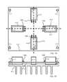
- FIGS. 4 a and 4 bshow a plan and side view respectively of a circuit board 400 and heat sink 406 according to an exemplary embodiment of the present invention.
- Circuit board 400has four switches S 1 , S 2 , S 3 and S 4 connected electrically to circuit board 400 via leads 408 .
- Switches S 1 , S 2 , S 3 and S 4are preferably insulated gate bipolar junction transistors (IGBTs).
- Switches S 1 , S 2 , S 3 and S 4are preferably connected electrically together according to full bridge converter 20 shown in FIG. 2 a .
- Circuit board 400is mechanically attached to heat sink 406 for instance via a screw and pillar arrangement 410 .
- Switches S 1 , S 2 , S 3 and S 4are mechanically and thermally attached to heat sink 406 . Cutouts CO 1 , CO 2 , CO 3 and CO 4 in circuit board 400 allow the mechanical and thermal attachment of switches S 1 , S 2 , S 3 and S 4 to heat sink 406 .
- switches S 1 , S 2 , S 3 and S 4are based upon a right-angle cross topology with dotted lines 404 and 402 forming the two arms of the right-angle cross topology.
- Switches S 1 and S 4lay on or symmetrically with respect to arm/axis 402 and switches S 2 and S 3 lay on an arm/axis 404 .
- the intersection between arm/axis 402 and arm/axis 404forms the cross portion of right-angle cross topology.
- perpendicular offsets of switches S 1 , S 4 , S 2 and S 3(and cutouts C 01 , CO 2 , CO 3 and C 04 in circuit board 400 ) relative to arms/axis 402 and arm/axis 404 respectively are made such that the offsets are in either a clockwise or anti-clockwise direction.
- a 50% switching duty cycleis applied to S 1 , S 2 , S 3 and S 4 such that while switches S 1 and S 4 are ON, switches S 3 and S 2 are OFF and vice versa.
- circuit board 400 and heat sink 406are mounted vertically so that the flow of heat in heat sink 506 generated by switches S 1 , S 2 , S 3 and S 4 flows vertically by convection.
- switches S 1 , S 2 , S 3 and S 4are such that for example; the heat in heat sink 406 from switches S 2 and S 3 does not flow near switches S 1 and S 4 and the distance between S 1 and S 4 is such that the vertical flow of heat in heat sink 406 of switches S 1 and S 4 does not affect each other.
- switches S 1 and S 4can be offset in either a clockwise or anti-clockwise direction, so that the vertical flow of heat in heat sink 406 of switches S 1 and S 4 does not affect each other.
- perpendicular offsets of switches S 1 , S 4 , S 2 and S 3 relative to arms/axis 402 and arm/axis 404 respectively and the distance between switches S 1 and S 4 along arm/axis 402 and switches S 2 and S 3 along arm/axis 404 respectivelyare preferably chosen in order to achieve minimal electromagnetic interference (EMI), minimal impedance of circuit board 400 traces and efficient heat transfer between switches S 1 , S 2 , S 3 and S 4 and heat sink 406 .
- EMIelectromagnetic interference
- FIGS. 5 a and 5 bshow a plan and side view respectively of a circuit board 500 and heat sink 506 according to an exemplary embodiment of the present invention.
- Circuit board 500has four switches S 1 , S 2 , S 3 and S 4 connected electrically to circuit board 500 via leads 508 .
- Switches S 1 , S 2 , S 3 and S 4are preferably insulated gate bipolar junction transistors (IGBTs).
- Switches S 1 , S 2 , S 3 and S 4are preferably connected electrically together according to full bridge converter 20 shown in FIG. 2 a .
- Circuit board 500is mechanically attached to heat sink 506 via a screw and pillar arrangement 510 .
- Switches S 1 , S 2 , S 3 and S 4are mechanically and thermally attached to heat sink 506 . Cutouts CO 1 , CO 2 , CO 3 and CO 4 in circuit board 500 allow the mechanical and thermal attachment of switches S 1 , S 2 , S 3 and S 4 to heat sink 506 .
- switches S 1 , S 2 , S 3 and S 4are based upon a fylfot cross topology.
- Switches S 1 and S 4lay parallel to arm/axis 502 and switches S 2 and S 3 lay parallel to arm/axis 504 .
- the intersection between arm/axis 502 and arm/axis 504form the right-angle cross portion of the fylfot cross topology.
- the hands of the fylfot cross topologyare represented by dotted lines as hand 512 , hand 516 , hand 514 and hand 518 .
- Hand 512 and hand 514represent respectively the offsets of switches S 1 and S 4 with respect to arm/axis 502 .
- Hand 516 and hand 518represent respectively the offsets of switches S 2 and S 3 with respect to arm/axis 504 .
- a hand 512 , hand 516 , hand 514 and hand 518are offset from axis/arms 502 and 504 in an anti-clockwise direction
- hand 512 , hand 516 , hand 514 and hand 518may be offset from axis/arms 502 and 504 in a clockwise direction.
- circuit board 500 and heat sink 506are mounted vertically so that the flow of heat in heat sink 506 generated by switches S 1 , S 2 , S 3 and S 4 flows vertically by convection. Using the plan view of FIG.
- switches S 1 , S 2 , S 3 and S 4are such that for example; the vertical flow of heat from switch S 2 does not significantly run into the vertical heat flow of switch S 1 , the vertical flow of heat from switch S 1 does not significantly run into the vertical heat flow of switch S 4 and the vertical flow of heat from switch S 4 does not run significantly into the vertical heat flow of switch S 3 .
Landscapes
- Engineering & Computer Science (AREA)
- Microelectronics & Electronic Packaging (AREA)
- Physics & Mathematics (AREA)
- Electromagnetism (AREA)
- Dc-Dc Converters (AREA)
Abstract
Description
Claims (12)
Priority Applications (2)
| Application Number | Priority Date | Filing Date | Title |
|---|---|---|---|
| US12/483,933US8630098B2 (en) | 2008-06-12 | 2009-06-12 | Switching circuit layout with heatsink |
| US14/143,699US20140185245A1 (en) | 2008-06-12 | 2013-12-30 | Switching circuit layout with heatsink |
Applications Claiming Priority (2)
| Application Number | Priority Date | Filing Date | Title |
|---|---|---|---|
| US6087808P | 2008-06-12 | 2008-06-12 | |
| US12/483,933US8630098B2 (en) | 2008-06-12 | 2009-06-12 | Switching circuit layout with heatsink |
Related Child Applications (1)
| Application Number | Title | Priority Date | Filing Date |
|---|---|---|---|
| US14/143,699ContinuationUS20140185245A1 (en) | 2008-06-12 | 2013-12-30 | Switching circuit layout with heatsink |
Publications (2)
| Publication Number | Publication Date |
|---|---|
| US20100124027A1 US20100124027A1 (en) | 2010-05-20 |
| US8630098B2true US8630098B2 (en) | 2014-01-14 |
Family
ID=42171896
Family Applications (2)
| Application Number | Title | Priority Date | Filing Date |
|---|---|---|---|
| US12/483,933Active2030-08-27US8630098B2 (en) | 2008-06-12 | 2009-06-12 | Switching circuit layout with heatsink |
| US14/143,699AbandonedUS20140185245A1 (en) | 2008-06-12 | 2013-12-30 | Switching circuit layout with heatsink |
Family Applications After (1)
| Application Number | Title | Priority Date | Filing Date |
|---|---|---|---|
| US14/143,699AbandonedUS20140185245A1 (en) | 2008-06-12 | 2013-12-30 | Switching circuit layout with heatsink |
Country Status (1)
| Country | Link |
|---|---|
| US (2) | US8630098B2 (en) |
Families Citing this family (60)
| Publication number | Priority date | Publication date | Assignee | Title |
|---|---|---|---|---|
| US10693415B2 (en) | 2007-12-05 | 2020-06-23 | Solaredge Technologies Ltd. | Testing of a photovoltaic panel |
| US11881814B2 (en) | 2005-12-05 | 2024-01-23 | Solaredge Technologies Ltd. | Testing of a photovoltaic panel |
| US8947194B2 (en) | 2009-05-26 | 2015-02-03 | Solaredge Technologies Ltd. | Theft detection and prevention in a power generation system |
| US11687112B2 (en) | 2006-12-06 | 2023-06-27 | Solaredge Technologies Ltd. | Distributed power harvesting systems using DC power sources |
| US8319483B2 (en) | 2007-08-06 | 2012-11-27 | Solaredge Technologies Ltd. | Digital average input current control in power converter |
| US11888387B2 (en) | 2006-12-06 | 2024-01-30 | Solaredge Technologies Ltd. | Safety mechanisms, wake up and shutdown methods in distributed power installations |
| US9130401B2 (en) | 2006-12-06 | 2015-09-08 | Solaredge Technologies Ltd. | Distributed power harvesting systems using DC power sources |
| US8816535B2 (en) | 2007-10-10 | 2014-08-26 | Solaredge Technologies, Ltd. | System and method for protection during inverter shutdown in distributed power installations |
| US8473250B2 (en) | 2006-12-06 | 2013-06-25 | Solaredge, Ltd. | Monitoring of distributed power harvesting systems using DC power sources |
| US12316274B2 (en) | 2006-12-06 | 2025-05-27 | Solaredge Technologies Ltd. | Pairing of components in a direct current distributed power generation system |
| US8618692B2 (en) | 2007-12-04 | 2013-12-31 | Solaredge Technologies Ltd. | Distributed power system using direct current power sources |
| US11309832B2 (en) | 2006-12-06 | 2022-04-19 | Solaredge Technologies Ltd. | Distributed power harvesting systems using DC power sources |
| US8319471B2 (en) | 2006-12-06 | 2012-11-27 | Solaredge, Ltd. | Battery power delivery module |
| US9112379B2 (en) | 2006-12-06 | 2015-08-18 | Solaredge Technologies Ltd. | Pairing of components in a direct current distributed power generation system |
| US11855231B2 (en) | 2006-12-06 | 2023-12-26 | Solaredge Technologies Ltd. | Distributed power harvesting systems using DC power sources |
| US11569659B2 (en) | 2006-12-06 | 2023-01-31 | Solaredge Technologies Ltd. | Distributed power harvesting systems using DC power sources |
| US11296650B2 (en) | 2006-12-06 | 2022-04-05 | Solaredge Technologies Ltd. | System and method for protection during inverter shutdown in distributed power installations |
| US11735910B2 (en) | 2006-12-06 | 2023-08-22 | Solaredge Technologies Ltd. | Distributed power system using direct current power sources |
| US8963369B2 (en) | 2007-12-04 | 2015-02-24 | Solaredge Technologies Ltd. | Distributed power harvesting systems using DC power sources |
| US9088178B2 (en) | 2006-12-06 | 2015-07-21 | Solaredge Technologies Ltd | Distributed power harvesting systems using DC power sources |
| US8013472B2 (en) | 2006-12-06 | 2011-09-06 | Solaredge, Ltd. | Method for distributed power harvesting using DC power sources |
| US8384243B2 (en) | 2007-12-04 | 2013-02-26 | Solaredge Technologies Ltd. | Distributed power harvesting systems using DC power sources |
| EP2225778B1 (en) | 2007-12-05 | 2019-06-26 | Solaredge Technologies Ltd. | Testing of a photovoltaic panel |
| WO2009072076A2 (en) | 2007-12-05 | 2009-06-11 | Solaredge Technologies Ltd. | Current sensing on a mosfet |
| US9291696B2 (en) | 2007-12-05 | 2016-03-22 | Solaredge Technologies Ltd. | Photovoltaic system power tracking method |
| US11264947B2 (en) | 2007-12-05 | 2022-03-01 | Solaredge Technologies Ltd. | Testing of a photovoltaic panel |
| CN105244905B (en) | 2007-12-05 | 2019-05-21 | 太阳能安吉有限公司 | Release mechanism in distributed power device is waken up and method for closing |
| WO2009073867A1 (en) | 2007-12-05 | 2009-06-11 | Solaredge, Ltd. | Parallel connected inverters |
| US8111052B2 (en) | 2008-03-24 | 2012-02-07 | Solaredge Technologies Ltd. | Zero voltage switching |
| EP2294669B8 (en) | 2008-05-05 | 2016-12-07 | Solaredge Technologies Ltd. | Direct current power combiner |
| EP2602831B1 (en) | 2009-05-22 | 2014-07-16 | Solaredge Technologies Ltd. | Electrically isolated heat dissipating junction box |
| US12418177B2 (en) | 2009-10-24 | 2025-09-16 | Solaredge Technologies Ltd. | Distributed power system using direct current power sources |
| US8710699B2 (en) | 2009-12-01 | 2014-04-29 | Solaredge Technologies Ltd. | Dual use photovoltaic system |
| US8766696B2 (en) | 2010-01-27 | 2014-07-01 | Solaredge Technologies Ltd. | Fast voltage level shifter circuit |
| US10230310B2 (en) | 2016-04-05 | 2019-03-12 | Solaredge Technologies Ltd | Safety switch for photovoltaic systems |
| US10673222B2 (en) | 2010-11-09 | 2020-06-02 | Solaredge Technologies Ltd. | Arc detection and prevention in a power generation system |
| GB2485527B (en) | 2010-11-09 | 2012-12-19 | Solaredge Technologies Ltd | Arc detection and prevention in a power generation system |
| US10673229B2 (en) | 2010-11-09 | 2020-06-02 | Solaredge Technologies Ltd. | Arc detection and prevention in a power generation system |
| GB2486408A (en) | 2010-12-09 | 2012-06-20 | Solaredge Technologies Ltd | Disconnection of a string carrying direct current |
| GB2483317B (en) | 2011-01-12 | 2012-08-22 | Solaredge Technologies Ltd | Serially connected inverters |
| US8570005B2 (en) | 2011-09-12 | 2013-10-29 | Solaredge Technologies Ltd. | Direct current link circuit |
| GB2498365A (en) | 2012-01-11 | 2013-07-17 | Solaredge Technologies Ltd | Photovoltaic module |
| US9853565B2 (en) | 2012-01-30 | 2017-12-26 | Solaredge Technologies Ltd. | Maximized power in a photovoltaic distributed power system |
| GB2498790A (en) | 2012-01-30 | 2013-07-31 | Solaredge Technologies Ltd | Maximising power in a photovoltaic distributed power system |
| GB2498791A (en) | 2012-01-30 | 2013-07-31 | Solaredge Technologies Ltd | Photovoltaic panel circuitry |
| GB2499991A (en) | 2012-03-05 | 2013-09-11 | Solaredge Technologies Ltd | DC link circuit for photovoltaic array |
| EP3499695B1 (en) | 2012-05-25 | 2024-09-18 | Solaredge Technologies Ltd. | Circuit for interconnected direct current power sources |
| US10115841B2 (en) | 2012-06-04 | 2018-10-30 | Solaredge Technologies Ltd. | Integrated photovoltaic panel circuitry |
| US9941813B2 (en) | 2013-03-14 | 2018-04-10 | Solaredge Technologies Ltd. | High frequency multi-level inverter |
| US9548619B2 (en) | 2013-03-14 | 2017-01-17 | Solaredge Technologies Ltd. | Method and apparatus for storing and depleting energy |
| EP3506370B1 (en) | 2013-03-15 | 2023-12-20 | Solaredge Technologies Ltd. | Bypass mechanism |
| JP6076865B2 (en)* | 2013-09-02 | 2017-02-08 | ルネサスエレクトロニクス株式会社 | Electronic equipment |
| US9318974B2 (en) | 2014-03-26 | 2016-04-19 | Solaredge Technologies Ltd. | Multi-level inverter with flying capacitor topology |
| US20170062793A1 (en)* | 2015-08-24 | 2017-03-02 | Elitise Llc | Contactor assembly for battery module |
| US11177663B2 (en) | 2016-04-05 | 2021-11-16 | Solaredge Technologies Ltd. | Chain of power devices |
| US11018623B2 (en) | 2016-04-05 | 2021-05-25 | Solaredge Technologies Ltd. | Safety switch for photovoltaic systems |
| US12057807B2 (en) | 2016-04-05 | 2024-08-06 | Solaredge Technologies Ltd. | Chain of power devices |
| US10945336B2 (en)* | 2018-06-13 | 2021-03-09 | Te Connectivity Corporation | Electronic device with relay mounted to substrate |
| CN110062518A (en)* | 2018-12-18 | 2019-07-26 | 厦门佐之记商贸有限公司 | A kind of PCB layout structure reducing electromagnetic interference |
| US11973414B2 (en)* | 2020-01-31 | 2024-04-30 | Schneider Electric It Corporation | Decoupled PCB structure to parallel power transistors |
Citations (141)
| Publication number | Priority date | Publication date | Assignee | Title |
|---|---|---|---|---|
| US3369210A (en) | 1965-07-28 | 1968-02-13 | Electro Nite | Electrical connector |
| US3596229A (en) | 1969-04-28 | 1971-07-27 | Wago Kontakttechnik Gmbh | Electrical connector |
| US4171861A (en) | 1976-08-18 | 1979-10-23 | Wago-Kontakttechnik Gmbh | Electrical distribution and/or connection device |
| US4452867A (en) | 1983-02-28 | 1984-06-05 | Pittway Corporation | Storage battery containing voltage reducing means |
| US4460232A (en) | 1982-05-24 | 1984-07-17 | Amp, Incorporated | Junction box for solar modules |
| US4623753A (en) | 1983-10-31 | 1986-11-18 | Amp Incorporated | Watertight junction box |
| US4637677A (en) | 1984-12-18 | 1987-01-20 | Amp Incorporated | Electrical connector |
| US4641079A (en) | 1984-02-20 | 1987-02-03 | Nippondenso Co., Ltd. | Battery voltage regulating system |
| US4783728A (en) | 1986-04-29 | 1988-11-08 | Modular Power Corp. | Modular power supply with PLL control |
| US4903851A (en) | 1988-07-07 | 1990-02-27 | Slough Donovan L | Molded plastic stud box support and box |
| US4987360A (en) | 1988-12-27 | 1991-01-22 | Bill's Ice Cream, Inc. | Self-contained rechargeable battery power source with voltage reducer |
| US5045988A (en) | 1990-07-31 | 1991-09-03 | Eaton Corporation | Isolated adjustable frequency AC inverter control |
| US5280232A (en) | 1990-11-30 | 1994-01-18 | Robert Bosch Gmbh | Method and apparatus for voltage regulation depending on battery charge |
| EP0420295B1 (en) | 1986-03-14 | 1994-01-19 | Itron, Inc. | An RF transponder for use in an automatic/remote instrument monitoring system |
| EP0604777A1 (en) | 1992-12-28 | 1994-07-06 | Motorola, Inc. | Data transmission device system and method |
| US5460546A (en) | 1993-03-08 | 1995-10-24 | Molex Incorporated | Electric connector terminal and method of marking the same |
| US5497289A (en) | 1992-09-30 | 1996-03-05 | Mitsubishi Denki Kabushiki Kaisha | Inverter apparatus and method therefor |
| US5548504A (en) | 1992-10-19 | 1996-08-20 | Canon Kabushiki Kaisha | Power line linking apparatus for linking a power generator to a commercial power line |
| US5604430A (en) | 1994-10-11 | 1997-02-18 | Trw Inc. | Solar array maximum power tracker with arcjet load |
| US5646501A (en) | 1995-11-02 | 1997-07-08 | Lucent Technologies Inc. | Flexible power architecture which supports multiple battery technologies for use with a portable device |
| US5773963A (en) | 1996-08-29 | 1998-06-30 | Apple Computer Inc. | Method and apparatus for programmably adjusting output voltage of a battery charger |
| US5780092A (en) | 1994-09-16 | 1998-07-14 | Kraft Foods, Inc, | Foaming coffee creamer and instant hot cappuccino |
| US5798631A (en) | 1995-10-02 | 1998-08-25 | The State Of Oregon Acting By And Through The State Board Of Higher Education On Behalf Of Oregon State University | Performance optimization controller and control method for doubly-fed machines |
| US5801519A (en) | 1996-06-21 | 1998-09-01 | The Board Of Trustees Of The University Of Illinois | Self-excited power minimizer/maximizer for switching power converters and switching motor drive applications |
| US5804894A (en) | 1996-08-16 | 1998-09-08 | Telxon Corporation | Low voltage battery pack monitoring circuit with adjustable set points |
| US5821734A (en) | 1997-08-29 | 1998-10-13 | Compaq Computer Corporation | Converting battery module with resistor programmation of default output voltage |
| US5822186A (en) | 1996-02-23 | 1998-10-13 | Apple Computer, Inc. | Auxiliary electrical component utilized on the exterior of an electrical device that can be removed when the electrical device is powered |
| US5838148A (en) | 1995-08-29 | 1998-11-17 | Canon Kabushiki Kaisha | Power control method and apparatus for battery power supply and battery power supply system |
| US5869956A (en) | 1996-09-06 | 1999-02-09 | Canon Kabushiki Kaisha | Solar power generation apparatus and power control device therefor |
| US5873738A (en) | 1994-05-19 | 1999-02-23 | Fujitsu Limited | Communication apparatus |
| US5892354A (en) | 1995-09-22 | 1999-04-06 | Canon Kabushiki Kaisha | Voltage control apparatus and method for power supply |
| US5923158A (en) | 1996-08-30 | 1999-07-13 | Canon Kabushiki Kaisha | Power control apparatus for solar power generation system |
| US5933327A (en)* | 1998-04-03 | 1999-08-03 | Ericsson, Inc. | Wire bond attachment of a integrated circuit package to a heat sink |
| US5945806A (en) | 1997-08-29 | 1999-08-31 | Compaq Computer Corporation | Variable-voltage programmable battery module |
| US5963010A (en) | 1996-10-31 | 1999-10-05 | Hitachi, Ltd. | Battery controller for controlling batteries of different kinds and including battery monitoring means for calculating remaining operation time and an information processing apparatus including such battery controller |
| US5990659A (en) | 1997-10-01 | 1999-11-23 | Telefonaktiebolaget Lm Ericsson | Battery pack that communicates intrinsic information over battery voltage terminals |
| US6031736A (en) | 1995-07-26 | 2000-02-29 | Canon Kabushiki Kaisha | Control apparatus of inverter and power generation system using such control apparatus |
| US6038148A (en)* | 1998-12-11 | 2000-03-14 | Ericsson, Inc. | Self-driven synchronous rectification scheme |
| US6046919A (en) | 1998-03-30 | 2000-04-04 | Sanyo Electric Co., Ltd. | Solar power generating device |
| US6050779A (en) | 1996-04-12 | 2000-04-18 | Canon Kabushiki Kaisha | Conveying apparatus using unstable electric power supply |
| US6082122A (en) | 1998-03-31 | 2000-07-04 | Sanyo Electric Co., Ltd. | Method for calibrating a measured value of detecting means |
| US6105317A (en) | 1997-09-24 | 2000-08-22 | Matsushita Electric Works, Ltd. | Mounting system for installing an array of solar battery modules of a panel-like configuration on a roof |
| US6111767A (en) | 1998-06-22 | 2000-08-29 | Heliotronics, Inc. | Inverter integrated instrumentation having a current-voltage curve tracer |
| US6111188A (en) | 1997-01-21 | 2000-08-29 | Canon Kabushiki Kaisha | Solar cell array and solar power generation apparatus using it |
| US6111391A (en) | 1998-09-11 | 2000-08-29 | Cullen; Richard A. | Controller for solar electric generator for recreational vehicles |
| US6163086A (en) | 1998-04-29 | 2000-12-19 | Samsung Electronics Co., Ltd. | Power supply circuit and a voltage level adjusting circuit and method for a portable battery-powered electronic device |
| US6166455A (en) | 1999-01-14 | 2000-12-26 | Micro Linear Corporation | Load current sharing and cascaded power supply modules |
| US6166527A (en) | 2000-03-27 | 2000-12-26 | Linear Technology Corporation | Control circuit and method for maintaining high efficiency in a buck-boost switching regulator |
| US6169678B1 (en) | 1999-01-28 | 2001-01-02 | Canon Kabushiki Kaisha | Photovoltaic power generation apparatus and control method thereof |
| US6259234B1 (en) | 1998-04-15 | 2001-07-10 | Agence Spatiale Europeenne | Converter module for an electrical power supply and a system including it |
| US6262558B1 (en) | 1997-11-27 | 2001-07-17 | Alan H Weinberg | Solar array system |
| US6285572B1 (en) | 1999-04-20 | 2001-09-04 | Sanyo Electric Co., Ltd. | Method of operating a power supply system having parallel-connected inverters, and power converting system |
| US6320769B2 (en) | 1999-12-01 | 2001-11-20 | Canon Kabushiki Kaisha | Interconnection power converter and power generation apparatus using the same |
| US6493246B2 (en) | 2000-09-29 | 2002-12-10 | Canon Kabushiki Kaisha | Power conversion with stop conversion during low integrated power conditions |
| US6531848B1 (en) | 2000-05-26 | 2003-03-11 | Arris International, Inc. | Battery voltage regulation circuit |
| US6545211B1 (en) | 1999-01-14 | 2003-04-08 | Canon Kabushiki Kaisha | Solar cell module, building material with solar cell module, solar cell module framing structure, and solar power generation apparatus |
| US6548205B2 (en) | 1998-10-20 | 2003-04-15 | The United States Of America As Represented By The Secretary Of The Army | Dual voltage multiple configuration battery and adapter |
| US20030080741A1 (en) | 2001-10-26 | 2003-05-01 | Lerow Kevin E. | Anti-islanding techniques for distributed power generation |
| JP2003134667A (en) | 2001-10-17 | 2003-05-09 | Mitsubishi Heavy Ind Ltd | Photovoltaic power generation device |
| US6590793B1 (en) | 1996-08-23 | 2003-07-08 | Canon Kabushiki Kaisha | Electric power supplying apparatus using unstable electric power supply and control method therefor |
| US6608468B2 (en) | 2000-09-25 | 2003-08-19 | Nec Mobile Energy Corporation | Battery pack compensating a cell voltage, a charge and discharge current and temperature data, by using a built-in CPU for the battery pack |
| US6611441B2 (en) | 2001-02-26 | 2003-08-26 | Canon Kabushiki Kaisha | Method of reducing leakage current in power supply systems |
| US6672018B2 (en) | 2001-10-12 | 2004-01-06 | Jefferson Shingleton | Solar module mounting method and clip |
| US6678174B2 (en) | 2000-11-27 | 2004-01-13 | Canon Kabushiki Kaisha | Power converting apparatus, control method therefor, and power generation system |
| US6690590B2 (en) | 2001-12-26 | 2004-02-10 | Ljubisav S. Stamenic | Apparatus for regulating the delivery of power from a DC power source to an active or passive load |
| US6738692B2 (en) | 2001-06-25 | 2004-05-18 | Sustainable Energy Technologies | Modular, integrated power conversion and energy management system |
| US6768047B2 (en) | 2002-06-13 | 2004-07-27 | Koninklijke Philips Electronics N.V. | Autonomous solid state lighting system |
| US6788033B2 (en) | 2002-08-08 | 2004-09-07 | Vlt, Inc. | Buck-boost DC-DC switching power conversion |
| WO2004023278A3 (en) | 2002-09-06 | 2004-09-10 | Nat Semiconductor Corp | Method and system for providing self-calibration for adaptively adjusting a power supply voltage in a digital processing system |
| US6795318B2 (en) | 2002-11-27 | 2004-09-21 | Hewlett-Packard Development Company, Lp. | Portable modular electronic system |
| US6801442B2 (en) | 2001-10-01 | 2004-10-05 | Canon Kabushiki Kaisha | Power conversion apparatus, power conversion system, and islanding operation detection method |
| US20040201279A1 (en) | 2003-04-11 | 2004-10-14 | Templeton James W. | Method and apparatus for improved DC power delivery management and configuration |
| WO2004107543A2 (en) | 2003-05-28 | 2004-12-09 | Beacon Power Corporation | Power converter for a solar panel |
| WO2004090993A3 (en) | 2003-04-02 | 2004-12-16 | Electricite De France | Pholtovoltaic panel which is secure against theft |
| US20050057214A1 (en) | 2003-09-15 | 2005-03-17 | Stefan Matan | Systems and methods for generating renewable energy |
| US20050057215A1 (en) | 2003-09-15 | 2005-03-17 | Stefan Matan | Systems and methods for charging a battery |
| US20050068820A1 (en) | 2003-09-30 | 2005-03-31 | Radosevich Lawrence D. | Bus structure for power switching circuits |
| EP1531545A2 (en) | 2003-11-14 | 2005-05-18 | Hitachi Industrial Equipment Systems Co. Ltd. | Filter apparatus and frequency converter to which the filter apparatus is connected |
| US6914418B2 (en) | 2003-04-21 | 2005-07-05 | Phoenixtec Power Co., Ltd. | Multi-mode renewable power converter system |
| US6919714B2 (en) | 2002-08-09 | 2005-07-19 | Alcatel | Circuit for conditioning a supply at the maximum power point |
| US20050172995A1 (en) | 2002-05-17 | 2005-08-11 | Rudiger Rohrig | Circuit arrangement for a photovoltaic system |
| WO2005076445A1 (en) | 2004-01-09 | 2005-08-18 | Philips Intellectual Property & Standards Gmbh | Decentralized power generation system |
| US6936995B2 (en) | 2003-02-25 | 2005-08-30 | General Motors Corporation | Battery voltage reduction |
| US6963147B2 (en) | 2003-03-07 | 2005-11-08 | Canon Kabushiki Kaisha | Power converter and power unit |
| US20060001406A1 (en) | 2004-07-01 | 2006-01-05 | Stefan Matan | Power extractor circuit |
| US6984970B2 (en) | 2002-09-19 | 2006-01-10 | Alcatel | Conditioning circuit for a power supply at the maximum power point, a solar generator, and a conditioning method |
| US20060038692A1 (en) | 2004-08-18 | 2006-02-23 | Schnetker Ted R | Circuit health monitoring system and method |
| US7030597B2 (en) | 2001-08-14 | 2006-04-18 | Somfy Sas | Photovoltaic-type charger |
| US7031176B2 (en) | 2002-07-15 | 2006-04-18 | Koninklijke Philips Electronics N.V. | Inverter |
| US7042195B2 (en) | 2004-09-13 | 2006-05-09 | Daihen Corporation | Method of controlling photovoltaic power generation system |
| US7046531B2 (en) | 2001-07-11 | 2006-05-16 | Squirrel Holdings Ltd. | Transformerless static voltage inverter for battery systems |
| US20060108979A1 (en) | 2004-11-25 | 2006-05-25 | Daniel Simon R | Rechargeable battery assembly |
| US7053506B2 (en) | 2001-01-16 | 2006-05-30 | Centre National De La Recherche Scientifique | Power converter control for automatic maximum power point tracking |
| US7072194B2 (en) | 2002-03-28 | 2006-07-04 | Curtin University Of Technology | Power conversion system and method of converting power |
| US7079406B2 (en) | 2000-03-29 | 2006-07-18 | Canon Kabushiki Kaisha | Power converting apparatus, control method therefor, and solar power generation apparatus |
| US20060162772A1 (en) | 2005-01-18 | 2006-07-27 | Presher Gordon E Jr | System and method for monitoring photovoltaic power generation systems |
| US7087332B2 (en) | 2002-07-31 | 2006-08-08 | Sustainable Energy Systems, Inc. | Power slope targeting for DC generators |
| US20060174939A1 (en) | 2004-12-29 | 2006-08-10 | Isg Technologies Llc | Efficiency booster circuit and technique for maximizing power point tracking |
| US7091707B2 (en) | 2003-09-29 | 2006-08-15 | Xantrex Technology, Inc. | Method and apparatus for controlling power drawn from an energy converter |
| US7090509B1 (en) | 1999-06-11 | 2006-08-15 | Stratos International, Inc. | Multi-port pluggable transceiver (MPPT) with multiple LC duplex optical receptacles |
| US20060185727A1 (en) | 2004-12-29 | 2006-08-24 | Isg Technologies Llc | Converter circuit and technique for increasing the output efficiency of a variable power source |
| US20060192540A1 (en) | 1998-02-27 | 2006-08-31 | Balu Balakrishnan | Off-line converter with digital control |
| US20060208660A1 (en) | 2005-03-18 | 2006-09-21 | Toyoda Jidosha Kabushiki Kaisha | Inverter unit for vehicle |
| US7126294B2 (en) | 2002-01-31 | 2006-10-24 | Ebara Corporation | Method and device for controlling photovoltaic inverter, and feed water device |
| US7126053B2 (en) | 2002-06-19 | 2006-10-24 | Canon Kabushiki Kaisha | Power generation system and power generation apparatus |
| US7148669B2 (en) | 2004-02-02 | 2006-12-12 | The Regents Of The University Of Colorado, A Body Corporate | Predictive digital current controllers for switching power converters |
| US20070013080A1 (en)* | 2005-06-29 | 2007-01-18 | Intel Corporation | Voltage regulators and systems containing same |
| US20070044837A1 (en) | 2005-08-29 | 2007-03-01 | Simburger Edward J | Nanosatellite solar cell regulator |
| JP2007058845A (en) | 2005-07-27 | 2007-03-08 | Gunma Prefecture | Photovoltaic power generator |
| ES2249147B1 (en) | 2004-07-01 | 2007-05-01 | Fundacion Robotiker | SMART PHOTOVOLTAIC MODULE. |
| WO2007006564B1 (en) | 2005-07-12 | 2007-05-31 | Rev Renewable Energy Ventures | Device for monitoring photovoltaic panels |
| US20070147075A1 (en)* | 2005-12-26 | 2007-06-28 | Lg.Philips Lcd Co., Ltd. | Backlight unit and liquid crystal display device having the same |
| US20070159866A1 (en) | 2005-01-28 | 2007-07-12 | Kasemsan Siri | Solar array inverter with maximum power tracking |
| WO2007084196A2 (en) | 2005-09-26 | 2007-07-26 | Atira Technologies, Llc | Dynamic switch power converter |
| WO2007113358A1 (en) | 2006-03-31 | 2007-10-11 | Univ Rovira I Virgili | Circuit and method for monitoring the point of maximum power for solar energy sources and solar generator incorporating said circuit |
| US7291036B1 (en) | 2006-11-08 | 2007-11-06 | Tyco Electronics Corporation | Photovoltaic connection system |
| US20080080177A1 (en)* | 2006-09-29 | 2008-04-03 | Hon Hai Precision Industry Co., Ltd. | Light emitting diode module and backlight system using the same |
| US20080097655A1 (en) | 2006-10-19 | 2008-04-24 | Tigo Energy, Inc. | Method and system to provide a distributed local energy production system with high-voltage DC bus |
| US7385833B2 (en) | 2005-06-03 | 2008-06-10 | Astec International Limited | Snubber circuit for a power converter |
| US20080136732A1 (en)* | 2006-12-06 | 2008-06-12 | O'connell John B | Method and structure for rf antenna module |
| US20080136367A1 (en) | 2006-12-06 | 2008-06-12 | Meir Adest | Battery power delivery module |
| US20080144294A1 (en) | 2006-12-06 | 2008-06-19 | Meir Adest | Removal component cartridge for increasing reliability in power harvesting systems |
| US7420815B2 (en) | 2003-11-06 | 2008-09-02 | Gateway Inc. | System for assembling computers to provide a favorable import classification |
| US20080238195A1 (en) | 2007-03-27 | 2008-10-02 | Shaver Argil E | Distributed maximum power point tracking system, structure and process |
| EP1657797B1 (en) | 2004-11-13 | 2008-10-08 | SMA Solar Technology AG | Protection device for apparatus carrying load current |
| US7435134B2 (en) | 2006-03-09 | 2008-10-14 | Sunpower Corporation, Systems | Photovoltaic module mounting clip with integral grounding |
| US7435897B2 (en) | 2002-04-11 | 2008-10-14 | Schott Solar, Inc. | Apparatus and method for mounting photovoltaic power generating systems on buildings |
| US20090084570A1 (en) | 2007-10-02 | 2009-04-02 | Tyco Electronics Corporation | Low Profile Photovoltaic (LPPV) Box |
| US7600349B2 (en) | 2003-02-26 | 2009-10-13 | Unirac, Inc. | Low profile mounting system |
| US20090282755A1 (en) | 2008-05-19 | 2009-11-19 | Powermount Systems, Inc. | Photovoltaic mounting system with locking connectors, adjustable rail height and hinge lock |
| US7759575B2 (en) | 2008-06-20 | 2010-07-20 | Tyco Electronics Corporation | Expandable power distribution unit |
| US7763807B2 (en) | 2007-11-27 | 2010-07-27 | Lumberg Connect Gmbh | Connector box for solar panel |
| US20100269430A1 (en) | 2007-06-06 | 2010-10-28 | Haddock Robert M M | Adjustable mounting assembly for standing seam panels |
| US20100282290A1 (en) | 2007-11-21 | 2010-11-11 | Solon Se | Photovoltaic unit comprising a matrix of frameless solar modules |
| US20100294903A1 (en) | 2009-05-25 | 2010-11-25 | Vadim Shmukler | Bracket for Connection of a Junction Box to Photovoltaic Panels |
| US20100297860A1 (en) | 2009-05-22 | 2010-11-25 | Vadim Shmukler | Dual compressive connector |
| US20100294528A1 (en) | 2009-05-22 | 2010-11-25 | Guy Sella | Electrically isolated heat dissipating junction box |
| US20110114154A1 (en) | 2009-11-19 | 2011-05-19 | Cogenra Solar, Inc. | Receiver for concentrating photovoltaic-thermal system |
| US7960650B2 (en) | 2008-05-03 | 2011-06-14 | Lumberg Connect Gmbh | Connection box for solar panel |
| US8003885B2 (en) | 2008-05-03 | 2011-08-23 | Lumberg Connect Gmbh | Connection box for solar panel |
| US20110271611A1 (en) | 2009-01-19 | 2011-11-10 | Marco Maracci | Universal fixing bracket for photovoltaic panels |
Family Cites Families (2)
| Publication number | Priority date | Publication date | Assignee | Title |
|---|---|---|---|---|
| US6200407B1 (en)* | 1994-08-18 | 2001-03-13 | Rockwell Technologies, Llc | Method of making a multilayer circuit board having a window exposing an enhanced conductive layer for use as an insulated mounting area |
| DE102005001148B3 (en)* | 2005-01-10 | 2006-05-18 | Siemens Ag | Electronic unit, has metal housing coupled to MOSFET operated with high frequency, where housing is arranged to metal plate over electrically-isolated isolation layer, and heat sink electrically connected with metal plate or housing |
- 2009
- 2009-06-12USUS12/483,933patent/US8630098B2/enactiveActive
- 2013
- 2013-12-30USUS14/143,699patent/US20140185245A1/ennot_activeAbandoned
Patent Citations (146)
| Publication number | Priority date | Publication date | Assignee | Title |
|---|---|---|---|---|
| US3369210A (en) | 1965-07-28 | 1968-02-13 | Electro Nite | Electrical connector |
| US3596229A (en) | 1969-04-28 | 1971-07-27 | Wago Kontakttechnik Gmbh | Electrical connector |
| US4171861A (en) | 1976-08-18 | 1979-10-23 | Wago-Kontakttechnik Gmbh | Electrical distribution and/or connection device |
| US4460232A (en) | 1982-05-24 | 1984-07-17 | Amp, Incorporated | Junction box for solar modules |
| US4452867A (en) | 1983-02-28 | 1984-06-05 | Pittway Corporation | Storage battery containing voltage reducing means |
| US4623753A (en) | 1983-10-31 | 1986-11-18 | Amp Incorporated | Watertight junction box |
| US4641079A (en) | 1984-02-20 | 1987-02-03 | Nippondenso Co., Ltd. | Battery voltage regulating system |
| US4637677A (en) | 1984-12-18 | 1987-01-20 | Amp Incorporated | Electrical connector |
| EP0420295B1 (en) | 1986-03-14 | 1994-01-19 | Itron, Inc. | An RF transponder for use in an automatic/remote instrument monitoring system |
| US4783728A (en) | 1986-04-29 | 1988-11-08 | Modular Power Corp. | Modular power supply with PLL control |
| US4903851A (en) | 1988-07-07 | 1990-02-27 | Slough Donovan L | Molded plastic stud box support and box |
| US4987360A (en) | 1988-12-27 | 1991-01-22 | Bill's Ice Cream, Inc. | Self-contained rechargeable battery power source with voltage reducer |
| US5045988A (en) | 1990-07-31 | 1991-09-03 | Eaton Corporation | Isolated adjustable frequency AC inverter control |
| US5280232A (en) | 1990-11-30 | 1994-01-18 | Robert Bosch Gmbh | Method and apparatus for voltage regulation depending on battery charge |
| US5497289A (en) | 1992-09-30 | 1996-03-05 | Mitsubishi Denki Kabushiki Kaisha | Inverter apparatus and method therefor |
| US5548504A (en) | 1992-10-19 | 1996-08-20 | Canon Kabushiki Kaisha | Power line linking apparatus for linking a power generator to a commercial power line |
| EP0604777A1 (en) | 1992-12-28 | 1994-07-06 | Motorola, Inc. | Data transmission device system and method |
| US5460546A (en) | 1993-03-08 | 1995-10-24 | Molex Incorporated | Electric connector terminal and method of marking the same |
| US5873738A (en) | 1994-05-19 | 1999-02-23 | Fujitsu Limited | Communication apparatus |
| US5780092A (en) | 1994-09-16 | 1998-07-14 | Kraft Foods, Inc, | Foaming coffee creamer and instant hot cappuccino |
| US5604430A (en) | 1994-10-11 | 1997-02-18 | Trw Inc. | Solar array maximum power tracker with arcjet load |
| US6031736A (en) | 1995-07-26 | 2000-02-29 | Canon Kabushiki Kaisha | Control apparatus of inverter and power generation system using such control apparatus |
| US5838148A (en) | 1995-08-29 | 1998-11-17 | Canon Kabushiki Kaisha | Power control method and apparatus for battery power supply and battery power supply system |
| US5892354A (en) | 1995-09-22 | 1999-04-06 | Canon Kabushiki Kaisha | Voltage control apparatus and method for power supply |
| US5798631A (en) | 1995-10-02 | 1998-08-25 | The State Of Oregon Acting By And Through The State Board Of Higher Education On Behalf Of Oregon State University | Performance optimization controller and control method for doubly-fed machines |
| US5646501A (en) | 1995-11-02 | 1997-07-08 | Lucent Technologies Inc. | Flexible power architecture which supports multiple battery technologies for use with a portable device |
| US5822186A (en) | 1996-02-23 | 1998-10-13 | Apple Computer, Inc. | Auxiliary electrical component utilized on the exterior of an electrical device that can be removed when the electrical device is powered |
| US6050779A (en) | 1996-04-12 | 2000-04-18 | Canon Kabushiki Kaisha | Conveying apparatus using unstable electric power supply |
| US5801519A (en) | 1996-06-21 | 1998-09-01 | The Board Of Trustees Of The University Of Illinois | Self-excited power minimizer/maximizer for switching power converters and switching motor drive applications |
| US5804894A (en) | 1996-08-16 | 1998-09-08 | Telxon Corporation | Low voltage battery pack monitoring circuit with adjustable set points |
| US6590793B1 (en) | 1996-08-23 | 2003-07-08 | Canon Kabushiki Kaisha | Electric power supplying apparatus using unstable electric power supply and control method therefor |
| US5773963A (en) | 1996-08-29 | 1998-06-30 | Apple Computer Inc. | Method and apparatus for programmably adjusting output voltage of a battery charger |
| US5923158A (en) | 1996-08-30 | 1999-07-13 | Canon Kabushiki Kaisha | Power control apparatus for solar power generation system |
| US5869956A (en) | 1996-09-06 | 1999-02-09 | Canon Kabushiki Kaisha | Solar power generation apparatus and power control device therefor |
| US5963010A (en) | 1996-10-31 | 1999-10-05 | Hitachi, Ltd. | Battery controller for controlling batteries of different kinds and including battery monitoring means for calculating remaining operation time and an information processing apparatus including such battery controller |
| US6111188A (en) | 1997-01-21 | 2000-08-29 | Canon Kabushiki Kaisha | Solar cell array and solar power generation apparatus using it |
| US5945806A (en) | 1997-08-29 | 1999-08-31 | Compaq Computer Corporation | Variable-voltage programmable battery module |
| US5821734A (en) | 1997-08-29 | 1998-10-13 | Compaq Computer Corporation | Converting battery module with resistor programmation of default output voltage |
| US6105317A (en) | 1997-09-24 | 2000-08-22 | Matsushita Electric Works, Ltd. | Mounting system for installing an array of solar battery modules of a panel-like configuration on a roof |
| US5990659A (en) | 1997-10-01 | 1999-11-23 | Telefonaktiebolaget Lm Ericsson | Battery pack that communicates intrinsic information over battery voltage terminals |
| US6262558B1 (en) | 1997-11-27 | 2001-07-17 | Alan H Weinberg | Solar array system |
| US20060192540A1 (en) | 1998-02-27 | 2006-08-31 | Balu Balakrishnan | Off-line converter with digital control |
| US6046919A (en) | 1998-03-30 | 2000-04-04 | Sanyo Electric Co., Ltd. | Solar power generating device |
| US6082122A (en) | 1998-03-31 | 2000-07-04 | Sanyo Electric Co., Ltd. | Method for calibrating a measured value of detecting means |
| US5933327A (en)* | 1998-04-03 | 1999-08-03 | Ericsson, Inc. | Wire bond attachment of a integrated circuit package to a heat sink |
| US6259234B1 (en) | 1998-04-15 | 2001-07-10 | Agence Spatiale Europeenne | Converter module for an electrical power supply and a system including it |
| US6163086A (en) | 1998-04-29 | 2000-12-19 | Samsung Electronics Co., Ltd. | Power supply circuit and a voltage level adjusting circuit and method for a portable battery-powered electronic device |
| US6339538B1 (en) | 1998-06-22 | 2002-01-15 | Clayton Kling Philips Handleman | Inverter circuit and method of operation |
| US6111767A (en) | 1998-06-22 | 2000-08-29 | Heliotronics, Inc. | Inverter integrated instrumentation having a current-voltage curve tracer |
| US6111391A (en) | 1998-09-11 | 2000-08-29 | Cullen; Richard A. | Controller for solar electric generator for recreational vehicles |
| US6548205B2 (en) | 1998-10-20 | 2003-04-15 | The United States Of America As Represented By The Secretary Of The Army | Dual voltage multiple configuration battery and adapter |
| US6038148A (en)* | 1998-12-11 | 2000-03-14 | Ericsson, Inc. | Self-driven synchronous rectification scheme |
| US6166455A (en) | 1999-01-14 | 2000-12-26 | Micro Linear Corporation | Load current sharing and cascaded power supply modules |
| US6545211B1 (en) | 1999-01-14 | 2003-04-08 | Canon Kabushiki Kaisha | Solar cell module, building material with solar cell module, solar cell module framing structure, and solar power generation apparatus |
| US6169678B1 (en) | 1999-01-28 | 2001-01-02 | Canon Kabushiki Kaisha | Photovoltaic power generation apparatus and control method thereof |
| US6285572B1 (en) | 1999-04-20 | 2001-09-04 | Sanyo Electric Co., Ltd. | Method of operating a power supply system having parallel-connected inverters, and power converting system |
| US7090509B1 (en) | 1999-06-11 | 2006-08-15 | Stratos International, Inc. | Multi-port pluggable transceiver (MPPT) with multiple LC duplex optical receptacles |
| US6320769B2 (en) | 1999-12-01 | 2001-11-20 | Canon Kabushiki Kaisha | Interconnection power converter and power generation apparatus using the same |
| US6166527A (en) | 2000-03-27 | 2000-12-26 | Linear Technology Corporation | Control circuit and method for maintaining high efficiency in a buck-boost switching regulator |
| US7079406B2 (en) | 2000-03-29 | 2006-07-18 | Canon Kabushiki Kaisha | Power converting apparatus, control method therefor, and solar power generation apparatus |
| US6531848B1 (en) | 2000-05-26 | 2003-03-11 | Arris International, Inc. | Battery voltage regulation circuit |
| US6608468B2 (en) | 2000-09-25 | 2003-08-19 | Nec Mobile Energy Corporation | Battery pack compensating a cell voltage, a charge and discharge current and temperature data, by using a built-in CPU for the battery pack |
| US6493246B2 (en) | 2000-09-29 | 2002-12-10 | Canon Kabushiki Kaisha | Power conversion with stop conversion during low integrated power conditions |
| US6678174B2 (en) | 2000-11-27 | 2004-01-13 | Canon Kabushiki Kaisha | Power converting apparatus, control method therefor, and power generation system |
| US7053506B2 (en) | 2001-01-16 | 2006-05-30 | Centre National De La Recherche Scientifique | Power converter control for automatic maximum power point tracking |
| US6611441B2 (en) | 2001-02-26 | 2003-08-26 | Canon Kabushiki Kaisha | Method of reducing leakage current in power supply systems |
| US6738692B2 (en) | 2001-06-25 | 2004-05-18 | Sustainable Energy Technologies | Modular, integrated power conversion and energy management system |
| US7046531B2 (en) | 2001-07-11 | 2006-05-16 | Squirrel Holdings Ltd. | Transformerless static voltage inverter for battery systems |
| US7030597B2 (en) | 2001-08-14 | 2006-04-18 | Somfy Sas | Photovoltaic-type charger |
| US6801442B2 (en) | 2001-10-01 | 2004-10-05 | Canon Kabushiki Kaisha | Power conversion apparatus, power conversion system, and islanding operation detection method |
| US6672018B2 (en) | 2001-10-12 | 2004-01-06 | Jefferson Shingleton | Solar module mounting method and clip |
| JP2003134667A (en) | 2001-10-17 | 2003-05-09 | Mitsubishi Heavy Ind Ltd | Photovoltaic power generation device |
| US20030080741A1 (en) | 2001-10-26 | 2003-05-01 | Lerow Kevin E. | Anti-islanding techniques for distributed power generation |
| US6690590B2 (en) | 2001-12-26 | 2004-02-10 | Ljubisav S. Stamenic | Apparatus for regulating the delivery of power from a DC power source to an active or passive load |
| US7126294B2 (en) | 2002-01-31 | 2006-10-24 | Ebara Corporation | Method and device for controlling photovoltaic inverter, and feed water device |
| US7072194B2 (en) | 2002-03-28 | 2006-07-04 | Curtin University Of Technology | Power conversion system and method of converting power |
| US7435897B2 (en) | 2002-04-11 | 2008-10-14 | Schott Solar, Inc. | Apparatus and method for mounting photovoltaic power generating systems on buildings |
| US20050172995A1 (en) | 2002-05-17 | 2005-08-11 | Rudiger Rohrig | Circuit arrangement for a photovoltaic system |
| US6768047B2 (en) | 2002-06-13 | 2004-07-27 | Koninklijke Philips Electronics N.V. | Autonomous solid state lighting system |
| US7126053B2 (en) | 2002-06-19 | 2006-10-24 | Canon Kabushiki Kaisha | Power generation system and power generation apparatus |
| US7031176B2 (en) | 2002-07-15 | 2006-04-18 | Koninklijke Philips Electronics N.V. | Inverter |
| US7087332B2 (en) | 2002-07-31 | 2006-08-08 | Sustainable Energy Systems, Inc. | Power slope targeting for DC generators |
| US6788033B2 (en) | 2002-08-08 | 2004-09-07 | Vlt, Inc. | Buck-boost DC-DC switching power conversion |
| US6919714B2 (en) | 2002-08-09 | 2005-07-19 | Alcatel | Circuit for conditioning a supply at the maximum power point |
| WO2004023278A3 (en) | 2002-09-06 | 2004-09-10 | Nat Semiconductor Corp | Method and system for providing self-calibration for adaptively adjusting a power supply voltage in a digital processing system |
| US6984970B2 (en) | 2002-09-19 | 2006-01-10 | Alcatel | Conditioning circuit for a power supply at the maximum power point, a solar generator, and a conditioning method |
| US6795318B2 (en) | 2002-11-27 | 2004-09-21 | Hewlett-Packard Development Company, Lp. | Portable modular electronic system |
| US6936995B2 (en) | 2003-02-25 | 2005-08-30 | General Motors Corporation | Battery voltage reduction |
| US7600349B2 (en) | 2003-02-26 | 2009-10-13 | Unirac, Inc. | Low profile mounting system |
| US7748175B2 (en) | 2003-02-26 | 2010-07-06 | Unirac, Inc. | Method of manufacturing and installing a low profile mounting system |
| US6963147B2 (en) | 2003-03-07 | 2005-11-08 | Canon Kabushiki Kaisha | Power converter and power unit |
| WO2004090993A3 (en) | 2003-04-02 | 2004-12-16 | Electricite De France | Pholtovoltaic panel which is secure against theft |
| US20040201279A1 (en) | 2003-04-11 | 2004-10-14 | Templeton James W. | Method and apparatus for improved DC power delivery management and configuration |
| US20060149396A1 (en) | 2003-04-11 | 2006-07-06 | Zilker Labs, Inc. | Point of load regulator having a pinstrapped configuration and which performs intelligent bus monitoring |
| US6914418B2 (en) | 2003-04-21 | 2005-07-05 | Phoenixtec Power Co., Ltd. | Multi-mode renewable power converter system |
| WO2004107543A2 (en) | 2003-05-28 | 2004-12-09 | Beacon Power Corporation | Power converter for a solar panel |
| US20050057214A1 (en) | 2003-09-15 | 2005-03-17 | Stefan Matan | Systems and methods for generating renewable energy |
| US20050057215A1 (en) | 2003-09-15 | 2005-03-17 | Stefan Matan | Systems and methods for charging a battery |
| US7091707B2 (en) | 2003-09-29 | 2006-08-15 | Xantrex Technology, Inc. | Method and apparatus for controlling power drawn from an energy converter |
| US20050068820A1 (en) | 2003-09-30 | 2005-03-31 | Radosevich Lawrence D. | Bus structure for power switching circuits |
| US7420815B2 (en) | 2003-11-06 | 2008-09-02 | Gateway Inc. | System for assembling computers to provide a favorable import classification |
| EP1531545A2 (en) | 2003-11-14 | 2005-05-18 | Hitachi Industrial Equipment Systems Co. Ltd. | Filter apparatus and frequency converter to which the filter apparatus is connected |
| WO2005076445A1 (en) | 2004-01-09 | 2005-08-18 | Philips Intellectual Property & Standards Gmbh | Decentralized power generation system |
| US7148669B2 (en) | 2004-02-02 | 2006-12-12 | The Regents Of The University Of Colorado, A Body Corporate | Predictive digital current controllers for switching power converters |
| US20060001406A1 (en) | 2004-07-01 | 2006-01-05 | Stefan Matan | Power extractor circuit |
| ES2249147B1 (en) | 2004-07-01 | 2007-05-01 | Fundacion Robotiker | SMART PHOTOVOLTAIC MODULE. |
| US20060038692A1 (en) | 2004-08-18 | 2006-02-23 | Schnetker Ted R | Circuit health monitoring system and method |
| US7042195B2 (en) | 2004-09-13 | 2006-05-09 | Daihen Corporation | Method of controlling photovoltaic power generation system |
| EP1657797B1 (en) | 2004-11-13 | 2008-10-08 | SMA Solar Technology AG | Protection device for apparatus carrying load current |
| US20060108979A1 (en) | 2004-11-25 | 2006-05-25 | Daniel Simon R | Rechargeable battery assembly |
| US20060174939A1 (en) | 2004-12-29 | 2006-08-10 | Isg Technologies Llc | Efficiency booster circuit and technique for maximizing power point tracking |
| US20060185727A1 (en) | 2004-12-29 | 2006-08-24 | Isg Technologies Llc | Converter circuit and technique for increasing the output efficiency of a variable power source |
| US20060162772A1 (en) | 2005-01-18 | 2006-07-27 | Presher Gordon E Jr | System and method for monitoring photovoltaic power generation systems |
| WO2006078685A3 (en) | 2005-01-18 | 2007-11-22 | Gordon E Presher Jr | System and method for monitoring photovoltaic power generation systems |
| US20070159866A1 (en) | 2005-01-28 | 2007-07-12 | Kasemsan Siri | Solar array inverter with maximum power tracking |
| US20060208660A1 (en) | 2005-03-18 | 2006-09-21 | Toyoda Jidosha Kabushiki Kaisha | Inverter unit for vehicle |
| US7385833B2 (en) | 2005-06-03 | 2008-06-10 | Astec International Limited | Snubber circuit for a power converter |
| US20070013080A1 (en)* | 2005-06-29 | 2007-01-18 | Intel Corporation | Voltage regulators and systems containing same |
| WO2007006564B1 (en) | 2005-07-12 | 2007-05-31 | Rev Renewable Energy Ventures | Device for monitoring photovoltaic panels |
| JP2007058845A (en) | 2005-07-27 | 2007-03-08 | Gunma Prefecture | Photovoltaic power generator |
| US20070044837A1 (en) | 2005-08-29 | 2007-03-01 | Simburger Edward J | Nanosatellite solar cell regulator |
| WO2007084196A2 (en) | 2005-09-26 | 2007-07-26 | Atira Technologies, Llc | Dynamic switch power converter |
| US20070147075A1 (en)* | 2005-12-26 | 2007-06-28 | Lg.Philips Lcd Co., Ltd. | Backlight unit and liquid crystal display device having the same |
| US7780472B2 (en) | 2006-03-09 | 2010-08-24 | Sunpower Corporation | Photovoltaic module mounting clip with integral grounding |
| US7435134B2 (en) | 2006-03-09 | 2008-10-14 | Sunpower Corporation, Systems | Photovoltaic module mounting clip with integral grounding |
| WO2007113358A1 (en) | 2006-03-31 | 2007-10-11 | Univ Rovira I Virgili | Circuit and method for monitoring the point of maximum power for solar energy sources and solar generator incorporating said circuit |
| US20080080177A1 (en)* | 2006-09-29 | 2008-04-03 | Hon Hai Precision Industry Co., Ltd. | Light emitting diode module and backlight system using the same |
| US20080097655A1 (en) | 2006-10-19 | 2008-04-24 | Tigo Energy, Inc. | Method and system to provide a distributed local energy production system with high-voltage DC bus |
| US7291036B1 (en) | 2006-11-08 | 2007-11-06 | Tyco Electronics Corporation | Photovoltaic connection system |
| US20080144294A1 (en) | 2006-12-06 | 2008-06-19 | Meir Adest | Removal component cartridge for increasing reliability in power harvesting systems |
| US20080136367A1 (en) | 2006-12-06 | 2008-06-12 | Meir Adest | Battery power delivery module |
| US20080136732A1 (en)* | 2006-12-06 | 2008-06-12 | O'connell John B | Method and structure for rf antenna module |
| US20080238195A1 (en) | 2007-03-27 | 2008-10-02 | Shaver Argil E | Distributed maximum power point tracking system, structure and process |
| US20100269430A1 (en) | 2007-06-06 | 2010-10-28 | Haddock Robert M M | Adjustable mounting assembly for standing seam panels |
| US20090084570A1 (en) | 2007-10-02 | 2009-04-02 | Tyco Electronics Corporation | Low Profile Photovoltaic (LPPV) Box |
| US20100282290A1 (en) | 2007-11-21 | 2010-11-11 | Solon Se | Photovoltaic unit comprising a matrix of frameless solar modules |
| US7763807B2 (en) | 2007-11-27 | 2010-07-27 | Lumberg Connect Gmbh | Connector box for solar panel |
| US7960650B2 (en) | 2008-05-03 | 2011-06-14 | Lumberg Connect Gmbh | Connection box for solar panel |
| US8003885B2 (en) | 2008-05-03 | 2011-08-23 | Lumberg Connect Gmbh | Connection box for solar panel |
| US20090282755A1 (en) | 2008-05-19 | 2009-11-19 | Powermount Systems, Inc. | Photovoltaic mounting system with locking connectors, adjustable rail height and hinge lock |
| US7759575B2 (en) | 2008-06-20 | 2010-07-20 | Tyco Electronics Corporation | Expandable power distribution unit |
| US20110271611A1 (en) | 2009-01-19 | 2011-11-10 | Marco Maracci | Universal fixing bracket for photovoltaic panels |
| US20100294528A1 (en) | 2009-05-22 | 2010-11-25 | Guy Sella | Electrically isolated heat dissipating junction box |
| US20100297860A1 (en) | 2009-05-22 | 2010-11-25 | Vadim Shmukler | Dual compressive connector |
| US20100294903A1 (en) | 2009-05-25 | 2010-11-25 | Vadim Shmukler | Bracket for Connection of a Junction Box to Photovoltaic Panels |
| US20110114154A1 (en) | 2009-11-19 | 2011-05-19 | Cogenra Solar, Inc. | Receiver for concentrating photovoltaic-thermal system |
Non-Patent Citations (26)
| Title |
|---|
| Alonso, "A New Distributed Converter Interface for PV Panels", 20th European Photovoltaic Solar Energy Conference, Jun. 6-10, 2005, Barcelona, Spain, pp. 2288-2291. |
| Alonso, "Experimental Results of Intelligent PV Module for Grid-Connected PV Systems", 21st European Photovoltaic Solar Energy Conference, Sep. 4-8, 2006, Dresden, Germany, pp. 2297-2300. |
| Alonso, et al., "Cascaded H-Bridge Multilevel Converter for Grid Connected Photovoltaic Generators with Independent Maximum Power Point Tracking of Each Solor Array", 2003 IEEE 34th, Annual Power Electronics Specialists Conference, Acapulco, Mexico, Jun. 15-19, 2003, pp. 731-735, vol. 2. |
| Chen, et al., "Predictive Digital Current Programmed Control", IEEE Transactions on Power Electronics, vol. 18, Issue 1, Jan. 2003. |
| Enslin, "Integrated Photovoltaic Maximum Power Point Tracking Converter", IEEE Transactions on Industrial Electronics, vol. 44, No. 6, Dec. 1997, pp. 769-773. |
| International Search Report for PCT/IB2007/004584 dated Jan. 28, 2009. |
| International Search Report for PCT/IB2007/004586 dated Mar. 5, 2009. |
| International Search Report for PCT/IB2007/004610 dated Feb. 23, 2009. |
| International Search Report for PCT/IB2007/004643 dated Jan. 30, 2009. |
| International Search Report for PCT/US2008/085736 dated Jan. 28, 2009. |
| International Search Report for PCT/US2008/085754 dated Feb. 9, 2009. |
| International Search Report for PCT/US2008/085755 dated Feb. 3, 2009. |
| Kajihara, et al., "Model of Photovoltaic Cell Circuits Under Partial Shading", 2005 IEEE, pp. 866-870. |
| Knaupp, et al., "Operation of a 10 KW PV Façade with 100 W AC Photovoltaic Modules", 1996 IEEE, 25th PVSC, May 13-17, 1996, pp. 1235-1238, Washington, DC. |
| Lindgren, "Topology for Decentralised Solar Energy Inverters with a Low Voltage AC-Bus", Chalmers University of Technology, Department of Electrical Power Engineering, EPE '99-Lausanne. |
| Myrzik, et al., "String and Module Integrated Inverters for Single-Phase Grid Connected Photovoltaic Systems-A Review", Power Tech Conference Proceedings, 2003 IEEE Bologna, Jun. 23-26, 2003, p. 8, vol. 2. |
| Nikraz, "Digital Control of a Voltage Source Inverter in a Photovoltaic Applications", 2004 35th Annual IEEE Power Electronics Specialists Conference, Aachen, Germany, 2004, pp. 3266-3271. |
| Orduz, "Evaluation Test Results of a New Distributed MPPT Converter", 22nd European Photovoltaic Solar Energy Conference, Sep. 3-7, 2007, Milan, Italy. |
| Palma, "A Modular Fuel Cell, Modular DC-DC Converter Concept for High Performance and Enhanced Reliability", IEEE 2007, pp. 2633-2638. |
| PCT/IB2010/052287 International Search Report and Written Opinion dated Sep. 2, 2010. |
| Quaschning, "Cost Effectiveness of Shadow Tolerant Photovoltaic Systems", Berlin University of Technology, Institute of Electrical Energy Technology, Renewable Energy Section. EuroSun '96, pp. 819-824. |
| Roman, "Intelligent PV Module for Grid-Connected PV Systems", IEEE Transactions on Industrial Electronics, vol. 52, No. 4, Aug. 2006, pp. 1066-1073. |
| Roman, "Power Line Communications in Modular PV Systems", 20th European Photovoltaic Solar Energy Conference, Jun. 6-10, 2005, Barcelona, Spain, pp. 2249-2252. |
| Uriarte, "Energy Integrated Management System for PV Applications", 20th European Photovoltaic Solar Energy Conference, Jun. 6-10, 2005, Barcelona, Spain, pp. 2292-2295. |
| Walker, "Cascaded DC-DC Converter Connection of Photovoltaic Modules", IEEE Transactions on Power Electronics, vol. 19, No. 4, Jul. 2004, pp. 1130-1139. |
| Wallace, et al., "DSP Controlled Buck/Boost Power Factor Correction for Telephony Rectifiers", Telecommunications Energy Conference 2001, INTELEC 2001, Twenty-Third International, Oct. 18, 2001, pp. 132-138. |
Also Published As
| Publication number | Publication date |
|---|---|
| US20100124027A1 (en) | 2010-05-20 |
| US20140185245A1 (en) | 2014-07-03 |
Similar Documents
| Publication | Publication Date | Title |
|---|---|---|
| US8630098B2 (en) | Switching circuit layout with heatsink | |
| Lu et al. | A high power-density and high efficiency insulated metal substrate based GaN HEMT power module | |
| US10123443B2 (en) | Semiconductor device | |
| Lu et al. | Opportunities and design considerations of GaN HEMTs in ZVS applications | |
| EP3073812B1 (en) | Integrated power electronics assembly module | |
| JPWO2018143429A1 (en) | Power semiconductor module and power conversion device | |
| CN105210464B (en) | Device and electrical assembly for converting a direct voltage into an alternating voltage | |
| Burkard et al. | Paralleling GaN switches for low voltage high current half-bridges | |
| US8897014B2 (en) | Mechanical layout for half-bridge power module that is optimized for low inductance | |
| US12408310B2 (en) | Power converter, heat exchanger, heat sink, and photovoltaic power generation system | |
| US20170117820A1 (en) | Semiconductor device | |
| JP6158051B2 (en) | Power converter | |
| Dusmez et al. | Designing a 1kW GaN PFC stage with over 99% efficiency and 155W/in 3 power density | |
| US8675379B2 (en) | Power converting apparatus having improved electro-thermal characteristics | |
| Santi et al. | Power electronic modules | |
| JP2018121406A (en) | Power converter | |
| Emon et al. | Design and optimization of 650V/60A double-sided cooled multichip GaN module | |
| Dutta et al. | A 3-D stacked wire bondless silicon carbide power module | |
| US10855196B2 (en) | Semiconductor device | |
| JP6362959B2 (en) | Power conversion circuit, manufacturing method thereof, and power conditioner | |
| Sato et al. | Development of high power density three-phase inverter | |
| Mirza et al. | A three-face utilized heat sink design for 3-D integrated 75 kVA intelligent power stage (IPS) | |
| Grzejszczak et al. | Design of a high-efficiency three-phase three-level NPC converter based on GaN HEMT and SiC SB diode | |
| Jenkins et al. | 125 W multiphase GaN/Si hybrid point of load converter for improved high load efficiency | |
| CN110266179A (en) | A layout method of SiC MOSFET converter and SiC MOSFET converter |
Legal Events
| Date | Code | Title | Description |
|---|---|---|---|
| AS | Assignment | Owner name:KREOS CAPITAL IV (EXPERT FUND) LIMITED, JERSEY Free format text:SECURITY AGREEMENT;ASSIGNOR:SOLAREDGE TECHNOLOGIES LTD.;REEL/FRAME:029634/0619 Effective date:20121228 | |
| AS | Assignment | Owner name:SOLAREDGE TECHNOLOGIES LTD., ISRAEL Free format text:ASSIGNMENT OF ASSIGNORS INTEREST;ASSIGNORS:HANDELSMAN, LIOR;GLOVINSKY, TZACHI;GROSSBERG, AMIR;AND OTHERS;SIGNING DATES FROM 20091117 TO 20091119;REEL/FRAME:029851/0947 | |
| FEPP | Fee payment procedure | Free format text:PAYOR NUMBER ASSIGNED (ORIGINAL EVENT CODE: ASPN); ENTITY STATUS OF PATENT OWNER: LARGE ENTITY | |
| STCF | Information on status: patent grant | Free format text:PATENTED CASE | |
| CC | Certificate of correction | ||
| FEPP | Fee payment procedure | Free format text:PAT HOLDER NO LONGER CLAIMS SMALL ENTITY STATUS, ENTITY STATUS SET TO UNDISCOUNTED (ORIGINAL EVENT CODE: STOL); ENTITY STATUS OF PATENT OWNER: LARGE ENTITY | |
| AS | Assignment | Owner name:SOLAREDGE TECHNOLOGIES LTD., ISRAEL Free format text:RELEASE BY SECURED PARTY;ASSIGNOR:KREOS CAPITAL IV (EXPERT FUND) LIMITED;REEL/FRAME:039129/0250 Effective date:20160623 | |
| FPAY | Fee payment | Year of fee payment:4 | |
| MAFP | Maintenance fee payment | Free format text:PAYMENT OF MAINTENANCE FEE, 8TH YEAR, LARGE ENTITY (ORIGINAL EVENT CODE: M1552); ENTITY STATUS OF PATENT OWNER: LARGE ENTITY Year of fee payment:8 | |
| FEPP | Fee payment procedure | Free format text:MAINTENANCE FEE REMINDER MAILED (ORIGINAL EVENT CODE: REM.); ENTITY STATUS OF PATENT OWNER: LARGE ENTITY |