US8629362B1 - Keyswitch using magnetic force - Google Patents
Keyswitch using magnetic forceDownload PDFInfo
- Publication number
- US8629362B1 US8629362B1US13/546,854US201213546854AUS8629362B1US 8629362 B1US8629362 B1US 8629362B1US 201213546854 AUS201213546854 AUS 201213546854AUS 8629362 B1US8629362 B1US 8629362B1
- Authority
- US
- United States
- Prior art keywords
- key
- magnetic
- key cap
- cap
- link
- Prior art date
- Legal status (The legal status is an assumption and is not a legal conclusion. Google has not performed a legal analysis and makes no representation as to the accuracy of the status listed.)
- Active
Links
Images


Classifications
- H—ELECTRICITY
- H01—ELECTRIC ELEMENTS
- H01H—ELECTRIC SWITCHES; RELAYS; SELECTORS; EMERGENCY PROTECTIVE DEVICES
- H01H13/00—Switches having rectilinearly-movable operating part or parts adapted for pushing or pulling in one direction only, e.g. push-button switch
- H01H13/50—Switches having rectilinearly-movable operating part or parts adapted for pushing or pulling in one direction only, e.g. push-button switch having a single operating member
- H01H13/52—Switches having rectilinearly-movable operating part or parts adapted for pushing or pulling in one direction only, e.g. push-button switch having a single operating member the contact returning to its original state immediately upon removal of operating force, e.g. bell-push switch
- H—ELECTRICITY
- H01—ELECTRIC ELEMENTS
- H01H—ELECTRIC SWITCHES; RELAYS; SELECTORS; EMERGENCY PROTECTIVE DEVICES
- H01H2215/00—Tactile feedback
- H01H2215/034—Separate snap action
- H01H2215/042—Permanent magnets
- H—ELECTRICITY
- H01—ELECTRIC ELEMENTS
- H01H—ELECTRIC SWITCHES; RELAYS; SELECTORS; EMERGENCY PROTECTIVE DEVICES
- H01H2221/00—Actuators
- H01H2221/036—Return force
- H01H2221/04—Return force magnetic
- H—ELECTRICITY
- H01—ELECTRIC ELEMENTS
- H01H—ELECTRIC SWITCHES; RELAYS; SELECTORS; EMERGENCY PROTECTIVE DEVICES
- H01H3/00—Mechanisms for operating contacts
- H01H3/02—Operating parts, i.e. for operating driving mechanism by a mechanical force external to the switch
- H01H3/12—Push-buttons
- H01H3/122—Push-buttons with enlarged actuating area, e.g. of the elongated bar-type; Stabilising means therefor
- H01H3/125—Push-buttons with enlarged actuating area, e.g. of the elongated bar-type; Stabilising means therefor using a scissor mechanism as stabiliser
Definitions
- Embodiments of the inventionsrelate to user input buttons and keyboards comprised thereof. More particularly, embodiments of the invention relate to magnetically biased keys, including those with a high degree of parallel motion.
- FIG. 1is a perspective view of keyboard employing keys of one embodiment of the invention.
- FIG. 2is a diagram of a key according to one embodiment of the invention with the key cap removed.
- FIG. 3Ais a cross-sectional diagram of a key of one embodiment of the invention in a depressed (actuated) configuration.
- FIG. 3Bis a sectional diagram of the key of FIG. 3A in a steady state (not actuated) orientation.
- FIG. 4Ais a cutaway view showing a single link of one embodiment in the invention.
- FIG. 4Bis a cutaway view of the keybase with both link members removed to expose the sensors.
- FIG. 5is a bottom view of a key of one embodiment of the invention with the key base removed.
- FIG. 6is a sectional view of FIG. 5 .
- FIG. 7is a diagram of a key of one embodiment of the invention with the key cap removed.
- FIGS. 8A and Bare schematic views of the button of an alternative embodiment of the invention.
- FIGS. 9A-Dare schematic views of a key of an alternative embodiment of the invention.
- FIG. 1is a perspective view of keyboard employing keys of one embodiment of the invention.
- Keyboard 100includes 8 keys 110 and a space bar 106 each of which may represent some embodiment of the invention as described further below.
- Each key 110includes a key cap 102 and a key base 104 .
- Key cap 102may provide a tactile indication such as depression 108 to allow a user to locate their fingers on the key.
- key caps 102 and key bases 104are injection molded from thermoplastic such as polycarbonate. Key bases are also commonly made of stamped metal. While this embodiment has eight keys, the key construction described below can be used on a keyboard with any number and any size of keys. By way of example, the techniques and structures could be used in a standard QWERTY style keyboard for a laptop or desktop computer.
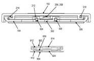
- FIG. 2is a diagram of a key according to one embodiment of the invention with the key cap removed.
- Key base 104may be molded from a thermoplastic.
- the capacitive sensing pad 216may overlay key base 104 .
- the capacitive sensing pad 216detects a keypress when a user's finger becomes more proximate to the sensing pad. A detectable change in capacitance occurs allowing determination of the keypress event. Further, the location of the finger during the keypress event may be determined by measuring the relative change in capacitance at sensing pad 216 as compared with a counterpart on the other side of the key.
- Key base 104may also define a plurality of axle housings 212 to rotationally engage axles (not shown) of link members 202 and 204 .
- Link members 202 and 204engage each other in an interleaved fashion through coupling members 206 and 208 .
- coupling members 206 and 208are magnetic masses such as steel that can be attracted to an underlying magnet (not shown) disposed in key base 104 .
- additional capacitive sensorsare provided within the key to detect delamination of the magnetic masses from the underlying magnet to signal a keypress event.
- capacitive sensing pad 216is formed as part of a flex circuit that may also include the additional capacitive sensors (discussed below with reference to FIG. 4 ).
- Link membersmay be formed of a combination of steel and plastic using an insert molding process. Generally a high rigidity plastic is selected. One suitable plastic is acetyl resin available under the trademark DELRIN from Dupont Corporation. In some embodiments one link member may be somewhat longer than the other. However, it is preferred to keep the link member relatively short such that neither link member exceeds a length of 70 percent of the maximum cross dimension of the key cap. Minimizing the length of link members 202 and 204 increases their stiffness which improves the parallelism during key depression. In one embodiment, neither link 202 nor link 204 exceeds 50 percent of the maximum cross dimension of the key cap.
- both link member 202 and 204are identical such that they can be manufactured in a single mold and simply flipped relative to one another for purposes of assembly.
- Each link member 202 and 204defines a pair of pegs 214 to engage slots (not shown) in the key cap.
- FIG. 3Ais a cross-sectional diagram of a key of one embodiment of the invention in a keypress down configuration.
- the magnetic massesin this case coupling numbers 206 and 208 , delaminate from magnet 302 resident in key base 104 .
- coupling members 206 , 208are formed of a ferromagnetic metal such as SUS430 stainless steel. Steel has high rigidity and durability and is well suited for this application.
- Other embodimentsmay have the coupling members made partially or entirely from a non-magnetic material, but use a magnetic mass disposed therein.
- a magnet 302may be a rare earth magnet which generates a suitable magnetic field which continues to exert an attractive force even after delamination of magnetic masses 206 , 208 from the magnet 302 , This field provides a force even when there is no contact between the magnet and magnetic mass, which force can raise the key back up after the user releases their finger press.
- the tactile feel for a useris controlled by the force vs. displacement curve, which may be adjusted by changes to the size and geometry of the magnet, magnetic masses, and relative axle location.
- a suitable magnetprovides a magnetic field sufficient to produce about 50 grams of button force in the completed assembly.
- an N52 magnet made of NdFeB materialhaving dimensions of about 10 by 1 by 1.4 millimeters is sufficient to provide at least 50 grams of force.
- link axles 304can be seen residing in axle housing 212 .
- Axlesare translationally fixed within axle housing 212 however; they are able to rotate to permit depression/actuation of the key cap 102 .
- peg members 214reside in slots 310 in the keycap 102 which permit the pegs to translate away from the center of the key sufficient distance to permit the key to be fully depressed.
- a gripping pad 306may be applied to the under surface of key base 104 to minimize movement of the keyboard on a supporting surface.
- gripping pad 306may be an elastomeric material with favorable frictional characteristics on common surfaces such as wood, metal, and plastic.
- the padis made from silicone rubber.
- FIG. 3Bis a sectional diagram of the key of FIG. 3A in a steady state orientation.
- this orientationAs a steady state orientation, Applicant intends to indicate that this is the state the key will adopt absent the application of an external force. This may also be thought of as the “up” state for the key.
- magnet 302is sufficiently close to magnetic masses 206 , 208 to be functionally laminated thereto.
- the back end of slots 310 in key cap 102 in conjunction with the magnetic lamination of the magnet to the magnetic massesboth provide hard stops that prevent the key from rising above the prescribed level in the steady state. Stops (not visible in this figure) are molded into key cap 102 such that the lateral translation of each of the links and pegs is limited by those hard stops. The hard stops also minimize the risk that the key cap will become detached from the links during normal use.
- FIG. 4Ais a cutaway view with the keycap removed showing a single link of one embodiment in the invention.
- Coupling member 202comprises upper interleaved member 406 and lower interleaved member 404 .
- Magnet 302is shown beneath the coupling members.
- Link 204(not shown in this Figure) would have mirror images of lower interleaved member 404 and upper interleaved member 406 such that the lower interleaved member for link 204 would overlay magnet 302 adjacent to lower interleaved member 404 and beneath upper interleaved member 406 .
- the upper interleaved member for link 204when installed is disposed above and in engagement with lower interleaved member 404 .
- FIG. 4Bis a cutaway view of the keybase with both link members removed to expose the sensors.
- Sensor 216(identified previously in FIG. 2 ) is a capacitive sensing pad formed of a copper pad area of the flex circuit adhered to the keybase 104 .
- Additional capacitive sensors 408 and 410are formed of additional copper pad areas on the same flex circuit. Sensors 408 and 410 each capacitively coupled to link members 202 and 204 respectively.
- the link membersare in contact with the magnet 302 , the metal surfaces of the magnetic masses 206 and 208 are in proximity to the additional sensors 408 and 410 , which causes an increased capacitive coupling.
- the magnetic masses 206 and 208delaminate from magnet 302 during a keypress event, the capacitive coupling is reduced. By monitoring this capacitive coupling, the up or down state of the key can be determined.
- FIG. 5is a bottom view of a key of one embodiment of the invention with the key base removed.
- links 202 and 204 and their respective lower interleaved members 402 and 502In this view can be seen links 202 and 204 and their respective lower interleaved members 402 and 502 .
- Upper interleaved member 504 of link 204resides in engagement with lower interleaved member 402 .
- Link axles 304are also visible.
- the hard stops 506 and 508may be molded as part of key cap 102 .
- the link-facing surface of hard stops 506 and 508is sloped to guide engagement as it approaches the bottom of travel during keypress.
- Slot housings 510may also be molded as part of key cap 102 . As discussed above, slot housings 510 define the slots in which pegs (element 214 from FIG. 3A ) translate during key actuation.
- FIG. 6is a sectional view of FIG. 5 .
- the sloped surface 602 of hard stop 508is clearly visible.
- surface 602limits the amount of distortion of the assembly if a lateral load is applied to the keycap and slots.
- surface 602resists lateral motion of pegs 214 within slots 310 to prevent unintended detachment of the key cap 102 from the key base 104 .
- FIG. 7is a diagram of a key of one embodiment of the invention with the key cap removed showing an additional perspective view in the steady state up orientation.
- Link membersare maintained in the steady state position by the magnetic field of the magnet underlying the interleaved coupling members 404 , 406 , 504 and 502 which mutually engage in an interleaved fashion as previously described.
- Capacitive sensing pad 216occupies substantially one half of surface area of the entire base of the key outside the magnetic region.
- Pegs 214are integrally molded as part of respective link members and engage slots in the key cap when the key cap is installed. The described structure permits highly parallel key with minimal tilt regardless of where on the keycap the keypress force is applied.
- the firm capacitive pad and magneteliminate the mushy tactile sensation at the bottom of travel commonly associated with the cylindrical actuator nib of rubber dome key mechanisms.
- the capacitive pad 216 and its counterpart on the other half of the key baseallows determination of a keypress, and may also be used to determine where on a key surface the key was pressed by a fingertip. This effectively allows for one key to provide multiple functions. However, as previously noted this structure may be applied to yield a superior tactile sensation even where small single-function keys are required.
- the replacement of the standard keyswitch scissor elements with the link membersimproves parallelism during actuation and eliminates the need for metal reinforcement bars on larger keys.
- the disclosed structurepermits construction of a key with a reduced part count and better feel. Additionally, the simpler nesting of the links allows larger size features such as axle, pegs etc., which are more robust than typical existing key structures resulting in greater durability.
- the magnetdoes not suffer from the kind of material stress or fatigue which limits the useful life of click domes and other prior art devices.
- the key cap and key baseare both injection-molded.
- the magnetmay have flanges which trap it in place in a recess in the key base, and further captured by an adhesive-backed polymer sheet affixed to the back of the key base.
- Adhesivesmay also be used to secure the magnet.
- the capacitive flexible circuit padis adhered to the key base with a pressure-sensitive adhesive tape backing.
- the link membersare interleaved and snapped into the axle housings and the pegs are snapped into the slots defined in the key cap.
- a base for a plurality of keysis injection-molded as a single unit that defines recesses for a plurality of magnets, at least one of which is associated with each key, and defines corresponding numbers of axle housings for each of the keys.
- the capacitive sensorsmay be instantiated as individual sensor components or as a single integrated flexible circuit panel with sensing pads for each key in the array of keys residing on a multi-key substrate. Each sensor can be electrically distinct to detect areas of a particular key. Further, a key can have one sensor pad, or a plurality of sensor pads in discrete spatial zones to facilitate measurement of the location of a fingertip on the keycap.
- FIGS. 8A and Bare schematic views of the button of an alternative embodiment of the invention.
- This embodimenthas only a single beam 802 coupled to an axle 806 which may be rotatably coupled to an axle housing.
- the button surface 804may be provided and may be concave, flat, or have other shapes or textures for tactile properties that may be desired.
- a magnetic massin this case magnet 808 , resides in the end of beam 802 .
- Magnet 808exerts the magnetic field on a magnetic mass 812 which may reside above magnet 808 when installed, such that the attraction biases the button into an up position.
- “magnetic mass”includes magnets and masses comprising ferromagnetic material upon which a magnet may exert an attractive or repulsive force.
- a capacitive sensorsenses the keypress while the delamination of the magnet 808 from the magnetic mass 812 provides a favorable tactile sensation over the travel responsive to the keypress. It is noted the while the above embodiment is described as having the permanent magnet resident in the beam 802 , the magnet 808 and magnetic mass 812 may be reversed without departing from the scope of the invention. In one embodiment a rare earth permanent magnet may be used, such as an N52 NdFeB magnet.
- This single beam embodimentis believed to be useful where perfect parallelism is less necessary.
- this embodimentmay be suitable for use with smart phones such as the “home” button on the iPhone (iPhone is a trademark of Apple Inc).
- Failure in the click domeis a common form of failure in existing iPhone smart phones. Because the magnetic mass and magnet do not experience wear during operation, failure of the home button can be significantly reduced. Additionally, less height is required due to the laterally juxtaposition of elements of the mechanism, thereby enabling creation of a thinner product.
- FIGS. 9 A-Dshow an alternative embodiment of a key in one embodiment of the invention.
- FIG. 9Ashow the key cap.
- FIG. 9Bshow the key base.
- FIGS. 9C and Dshow the key in an Up and a Down state respectively.
- a key using magnetic forces without any beamscan be realized through an assembly of magnets.
- the key cap 902contains four magnets (exemplified by 912 ) at the inside of each corner, and another magnet 914 in the center. These 5 magnets form pairs with counterparts 922 , 924 in the key base 904 .
- the outer four pairs 912 , 922comprise oppositely polarized magnets, which attract the keycap 902 to the key base 904 .
- the center magnet pair 922 , 924has matched polarity providing a repulsive force which causes the key cap to elevate to an Up position. A user overcomes this repulsive force when he presses on the key.
- the outer attractive magnets 912 , 922register the key cap 902 to the key base 904 , and effectively “attach” the key cap 902 and key base 904 via the magnetic field strength.
- the center magnets 914 , 924effectively provide a spring function to push the key cap 902 up. In this way, a keyswitch can be realized without additional moving parts or wear. Since actuation is guided by magnetic fields without any wiping surfaces, it provides extraordinarly smooth motion and superior feel.
- a keypress eventmay be detected with capacitive sensor pads 930 affixed to the key base 904 . These sensors 930 can detect a human finger on a keypress event, or they can detect the proximity of the key cap 902 magnets to the key base 904 sensor pads based upon their effect on the capacitance or electric field seen by the plate. Additional metallic elements may be placed in the key cap 902 to interact with the sensor pads 930 to detect a keypress. Hall effect sensors may be alternatively used to detect changes in the magnetic fields as the keypress event occurs. It is also contemplated that a physical contact switch on a membrane panel in the key base 904 could be used, although such metallic contact elements have more limited life than the field-sensing embodiments.
Landscapes
- Input From Keyboards Or The Like (AREA)
- Push-Button Switches (AREA)
Abstract
Description
Claims (11)
Priority Applications (2)
| Application Number | Priority Date | Filing Date | Title |
|---|---|---|---|
| US13/546,854US8629362B1 (en) | 2012-07-11 | 2012-07-11 | Keyswitch using magnetic force |
| US14/153,983US9728353B2 (en) | 2012-07-11 | 2014-01-13 | Keyswitch using magnetic force |
Applications Claiming Priority (1)
| Application Number | Priority Date | Filing Date | Title |
|---|---|---|---|
| US13/546,854US8629362B1 (en) | 2012-07-11 | 2012-07-11 | Keyswitch using magnetic force |
Related Child Applications (1)
| Application Number | Title | Priority Date | Filing Date |
|---|---|---|---|
| US14/153,983DivisionUS9728353B2 (en) | 2012-07-11 | 2014-01-13 | Keyswitch using magnetic force |
Publications (2)
| Publication Number | Publication Date |
|---|---|
| US8629362B1true US8629362B1 (en) | 2014-01-14 |
| US20140014486A1 US20140014486A1 (en) | 2014-01-16 |
Family
ID=49886060
Family Applications (2)
| Application Number | Title | Priority Date | Filing Date |
|---|---|---|---|
| US13/546,854ActiveUS8629362B1 (en) | 2012-07-11 | 2012-07-11 | Keyswitch using magnetic force |
| US14/153,983Expired - Fee RelatedUS9728353B2 (en) | 2012-07-11 | 2014-01-13 | Keyswitch using magnetic force |
Family Applications After (1)
| Application Number | Title | Priority Date | Filing Date |
|---|---|---|---|
| US14/153,983Expired - Fee RelatedUS9728353B2 (en) | 2012-07-11 | 2014-01-13 | Keyswitch using magnetic force |
Country Status (1)
| Country | Link |
|---|---|
| US (2) | US8629362B1 (en) |
Cited By (42)
| Publication number | Priority date | Publication date | Assignee | Title |
|---|---|---|---|---|
| US20140251772A1 (en)* | 2013-03-10 | 2014-09-11 | Apple Inc. | Rattle-free keyswitch mechanism |
| US20140262717A1 (en)* | 2013-03-14 | 2014-09-18 | Synaptics Incorporated | Anti-tilt and rotation techniques for a touchsurface assembly having translating keys |
| US9064651B2 (en)* | 2011-11-17 | 2015-06-23 | Darfon Electronics Corp. | Keyswitch |
| US20150243456A1 (en)* | 2011-11-17 | 2015-08-27 | Darfon Electronics Corp. | Keyswitch |
| USD757008S1 (en)* | 2013-04-08 | 2016-05-24 | Synerdyne Corporation | Keyboard |
| US9412533B2 (en) | 2013-05-27 | 2016-08-09 | Apple Inc. | Low travel switch assembly |
| US9449772B2 (en) | 2012-10-30 | 2016-09-20 | Apple Inc. | Low-travel key mechanisms using butterfly hinges |
| US9502193B2 (en) | 2012-10-30 | 2016-11-22 | Apple Inc. | Low-travel key mechanisms using butterfly hinges |
| US9640347B2 (en) | 2013-09-30 | 2017-05-02 | Apple Inc. | Keycaps with reduced thickness |
| CN106774962A (en)* | 2016-12-27 | 2017-05-31 | 南昌欧菲显示科技有限公司 | Keyboard and electronic device |
| US9704670B2 (en) | 2013-09-30 | 2017-07-11 | Apple Inc. | Keycaps having reduced thickness |
| US9704665B2 (en) | 2014-05-19 | 2017-07-11 | Apple Inc. | Backlit keyboard including reflective component |
| US9710069B2 (en) | 2012-10-30 | 2017-07-18 | Apple Inc. | Flexible printed circuit having flex tails upon which keyboard keycaps are coupled |
| US9715978B2 (en) | 2014-05-27 | 2017-07-25 | Apple Inc. | Low travel switch assembly |
| US9779889B2 (en) | 2014-03-24 | 2017-10-03 | Apple Inc. | Scissor mechanism features for a keyboard |
| US9793066B1 (en) | 2014-01-31 | 2017-10-17 | Apple Inc. | Keyboard hinge mechanism |
| US20170322634A1 (en)* | 2016-05-09 | 2017-11-09 | Dell Products, Lp | Keyboard key with user-configurable typing force |
| US20170365423A1 (en)* | 2016-06-16 | 2017-12-21 | Darfon Electronics (Suzhou) Co., Ltd. | Keyswitch |
| US9870880B2 (en) | 2014-09-30 | 2018-01-16 | Apple Inc. | Dome switch and switch housing for keyboard assembly |
| US9908310B2 (en) | 2013-07-10 | 2018-03-06 | Apple Inc. | Electronic device with a reduced friction surface |
| US9927895B2 (en) | 2013-02-06 | 2018-03-27 | Apple Inc. | Input/output device with a dynamically adjustable appearance and function |
| US9934915B2 (en) | 2015-06-10 | 2018-04-03 | Apple Inc. | Reduced layer keyboard stack-up |
| US9971084B2 (en) | 2015-09-28 | 2018-05-15 | Apple Inc. | Illumination structure for uniform illumination of keys |
| US9997308B2 (en) | 2015-05-13 | 2018-06-12 | Apple Inc. | Low-travel key mechanism for an input device |
| US9997304B2 (en) | 2015-05-13 | 2018-06-12 | Apple Inc. | Uniform illumination of keys |
| US10083805B2 (en) | 2015-05-13 | 2018-09-25 | Apple Inc. | Keyboard for electronic device |
| US10082880B1 (en) | 2014-08-28 | 2018-09-25 | Apple Inc. | System level features of a keyboard |
| US10115544B2 (en) | 2016-08-08 | 2018-10-30 | Apple Inc. | Singulated keyboard assemblies and methods for assembling a keyboard |
| US10128064B2 (en) | 2015-05-13 | 2018-11-13 | Apple Inc. | Keyboard assemblies having reduced thicknesses and method of forming keyboard assemblies |
| US10353485B1 (en) | 2016-07-27 | 2019-07-16 | Apple Inc. | Multifunction input device with an embedded capacitive sensing layer |
| US10381175B2 (en)* | 2017-10-20 | 2019-08-13 | Darfon Electronics Corp. | Key structure |
| US10491214B2 (en) | 2017-01-27 | 2019-11-26 | Dell Products L.P. | Systems and methods for implementing retractable and/or variable depression force key assemblies |
| US10547310B2 (en) | 2017-01-27 | 2020-01-28 | Dell Products L.P. | Systems and methods for indicating real time availability of key assemblies for user input to an information handling system |
| US10574233B2 (en) | 2017-01-27 | 2020-02-25 | Dell Products L.P. | Retractable and/or variable depression force key assemblies and methods for using the same |
| US10692667B1 (en)* | 2018-12-21 | 2020-06-23 | Primax Electronics Ltd. | Keyboard keycap connecting element |
| US10755877B1 (en) | 2016-08-29 | 2020-08-25 | Apple Inc. | Keyboard for an electronic device |
| USD894184S1 (en)* | 2018-05-18 | 2020-08-25 | Compal Information (Kunshan) Co., Ltd | Keyboard |
| US10775850B2 (en) | 2017-07-26 | 2020-09-15 | Apple Inc. | Computer with keyboard |
| US10796863B2 (en) | 2014-08-15 | 2020-10-06 | Apple Inc. | Fabric keyboard |
| US10991523B2 (en)* | 2018-07-24 | 2021-04-27 | Chicony Electronics Co, , Ltd. | Keyboard device |
| US11500538B2 (en) | 2016-09-13 | 2022-11-15 | Apple Inc. | Keyless keyboard with force sensing and haptic feedback |
| USD989072S1 (en)* | 2021-10-01 | 2023-06-13 | Peter Changhee Park | Stenography keyboard |
Families Citing this family (8)
| Publication number | Priority date | Publication date | Assignee | Title |
|---|---|---|---|---|
| KR101642884B1 (en) | 2011-01-05 | 2016-08-10 | 레이저 (아시아-퍼시픽) 피티이 엘티디 | Optically transmissive key assemblies for display-capable keyboards, keypads, or other user input devices |
| CN104684855B (en)* | 2012-09-28 | 2018-03-30 | 东芝机械株式会社 | Shaped device and forming method |
| US9158390B2 (en)* | 2013-03-08 | 2015-10-13 | Darren C. PETERSEN | Mechanical actuator apparatus for a touch sensing surface of an electronic device |
| US9164595B2 (en)* | 2013-03-08 | 2015-10-20 | Darren C. PETERSEN | Mechanical actuator apparatus for a touchscreen |
| CN104299821B (en)* | 2014-09-25 | 2017-03-08 | 苏州达方电子有限公司 | Press-key structure |
| AU2014410786B2 (en)* | 2014-11-05 | 2018-06-07 | Razer (Asia-Pacific) Pte. Ltd. | Input devices |
| US10394342B2 (en)* | 2017-09-27 | 2019-08-27 | Facebook Technologies, Llc | Apparatuses, systems, and methods for representing user interactions with real-world input devices in a virtual space |
| TWI674520B (en)* | 2018-08-07 | 2019-10-11 | 群光電子股份有限公司 | keyboard |
Citations (114)
| Publication number | Priority date | Publication date | Assignee | Title |
|---|---|---|---|---|
| US1652464A (en) | 1926-02-08 | 1927-12-13 | Tyberg Oluf | Typewriter keyboard |
| US2532228A (en) | 1946-07-26 | 1950-11-28 | Frank H Hesh | Electrically operated typewriter |
| US3399287A (en) | 1964-06-03 | 1968-08-27 | Gen Electric | Rockable plate type actuator for a plurality of contacts |
| US3633724A (en) | 1970-01-22 | 1972-01-11 | Ronald A Samuel | Electric typewriter key and keyboard arrangement |
| US4054944A (en)* | 1975-01-17 | 1977-10-18 | Redactron Corporation | Finger operated switching device |
| US4201489A (en) | 1976-08-04 | 1980-05-06 | Creatcchnil Patent AG | Keyboard actuatable with the aid of the fingers of at least one hand |
| US4256931A (en) | 1979-08-27 | 1981-03-17 | Interstate Industries, Inc. | Multiple dome switch assembly having pivotable common actuator |
| US4440515A (en) | 1982-06-01 | 1984-04-03 | International Business Machines Corporation | Keybar keyboard |
| US4449839A (en) | 1982-09-22 | 1984-05-22 | Bleuer Keith T | Keyboard with elongate keys |
| US4536625A (en) | 1983-04-20 | 1985-08-20 | Bebie Alain M | Keyboard design |
| US4584443A (en) | 1984-05-14 | 1986-04-22 | Honeywell Inc. | Captive digit input device |
| US4654647A (en) | 1984-09-24 | 1987-03-31 | Wedam Jack M | Finger actuated electronic control apparatus |
| US4719455A (en) | 1986-01-24 | 1988-01-12 | Louis William M | Integrating pointing device |
| US4761522A (en) | 1986-10-06 | 1988-08-02 | Allen Donald E | Finger operated switching apparatus |
| US4778295A (en) | 1984-06-25 | 1988-10-18 | Bleuer Keith T | Keyboard with elongate keys associated with compact switch mechanisms |
| US4896003A (en) | 1989-06-30 | 1990-01-23 | Hsieh Man Ching | Multi-position electrical switch |
| US4913573A (en) | 1987-02-18 | 1990-04-03 | Retter Dale J | Alpha-numeric keyboard |
| US4935728A (en) | 1985-01-02 | 1990-06-19 | Altra Corporation | Computer control |
| US4964075A (en) | 1987-05-08 | 1990-10-16 | A. J. Weiner, Inc. | Software and hardware independent auxiliary user programmable intelligent keyboard |
| US5012230A (en) | 1987-04-07 | 1991-04-30 | Sony Corporation | Input device for digital processor based apparatus |
| US5017030A (en) | 1986-07-07 | 1991-05-21 | Crews Jay A | Ergonomically designed keyboard |
| US5086296A (en) | 1987-12-02 | 1992-02-04 | U.S. Philips Corporation | Signal generating device |
| US5087910A (en) | 1985-07-29 | 1992-02-11 | Guyot Sionnest Laurent | Electronic keyboard for one-hand operation |
| US5252952A (en) | 1990-10-26 | 1993-10-12 | The Cherry Corporation | Cursor device with zero-point resetting |
| US5383735A (en) | 1993-07-23 | 1995-01-24 | Smith Corona Corporation | Miniature keyboard with sliding keys |
| US5424516A (en) | 1993-09-23 | 1995-06-13 | Emmons; Charles E. | Low profile pushbutton switch |
| US5424728A (en) | 1990-07-10 | 1995-06-13 | Goldstein; Mark | Keyboard |
| US5497151A (en) | 1991-10-24 | 1996-03-05 | Dombroski; Michael L. | Compact one-handed typing keyboard having keys corresponding to a standard two-handed keyboard |
| US5504502A (en) | 1990-09-18 | 1996-04-02 | Fujitsu Limited | Pointing control device for moving a cursor on a display on a computer |
| US5528235A (en) | 1991-09-03 | 1996-06-18 | Edward D. Lin | Multi-status multi-function data processing key and key array |
| US5564560A (en) | 1995-06-07 | 1996-10-15 | Garmin Corporation | Dual function button |
| US5644338A (en) | 1993-05-26 | 1997-07-01 | Bowen; James H. | Ergonomic laptop computer and ergonomic keyboard |
| US5661505A (en) | 1995-01-13 | 1997-08-26 | Livits; Eric A. | Single hand-controlled computer input device |
| US5666138A (en) | 1994-11-22 | 1997-09-09 | Culver; Craig F. | Interface control |
| US5772008A (en)* | 1996-07-08 | 1998-06-30 | Behavior Tech Computer Corporation | Keyboard switch actuator assembly including keycap and scissors type linkage |
| US5790108A (en) | 1992-10-23 | 1998-08-04 | University Of British Columbia | Controller |
| US5808603A (en) | 1997-02-06 | 1998-09-15 | Chen; Mei Yun | Computer input device |
| US5818361A (en) | 1996-11-07 | 1998-10-06 | Acevedo; Elkin | Display keyboard |
| US5841635A (en) | 1997-09-29 | 1998-11-24 | Ericsson, Inc. | Flexible printed circuit for split keyboard and method of assembly |
| US5841374A (en) | 1997-01-28 | 1998-11-24 | Abraham; Joseph N. | Micro word-pad with tactile multifunctional keys |
| US6031469A (en) | 1996-11-12 | 2000-02-29 | Dodd; Jerry | Ergonomic computer keyboard |
| US6046754A (en) | 1997-11-04 | 2000-04-04 | Gateway 2000, Inc. | Display shutter device for view protection on a portable computer |
| US6075522A (en) | 1998-03-26 | 2000-06-13 | Altra Corporation | Desktop compact cursor controller structure for use with computers and keyboards |
| US6103979A (en) | 1993-08-26 | 2000-08-15 | Fujitsu Limited | Keyboard having plurality of keys therein, each key establishing different electric contacts |
| US6157323A (en) | 1998-02-25 | 2000-12-05 | Tso; Kevin H. K. | Button-key/cylindrical-key alphabetizer |
| US6168331B1 (en) | 1999-12-16 | 2001-01-02 | Charles S. Vann | Case keyboard |
| US6204839B1 (en) | 1997-06-27 | 2001-03-20 | Compaq Computer Corporation | Capacitive sensing keyboard and pointing device |
| US6230222B1 (en) | 1998-10-29 | 2001-05-08 | Martha Torell Rush | Prioritizing input device having a circuit indicating the highest priority key value when a plurality of keys being simultaneously selected |
| US20010006587A1 (en) | 1999-12-30 | 2001-07-05 | Nokia Mobile Phones Ltd. | Keyboard arrangement |
| US6307537B1 (en) | 1998-07-23 | 2001-10-23 | Kyocera Corporation | Multifunction key for use with portable device |
| US6348878B1 (en) | 2000-08-10 | 2002-02-19 | Kenzo Tsubai | Data entry keyboard |
| US20020027549A1 (en) | 2000-03-03 | 2002-03-07 | Jetway Technologies Ltd. | Multifunctional keypad on touch screen |
| US20020037715A1 (en) | 1998-06-15 | 2002-03-28 | Sbc Technology Resources, Inc. | Enhanced wireless handset, including direct handset-to-handset communication mode |
| US6386773B1 (en) | 2000-03-10 | 2002-05-14 | Joseph Mathias | Ergonomic keyboard |
| US20020085337A1 (en) | 2001-01-04 | 2002-07-04 | Apple Computer, Inc. | Keyboard arrangement |
| US6417838B1 (en) | 1999-04-26 | 2002-07-09 | Alps Electric Co., Ltd. | Electronic equipment having input device that permits operations, including positional control in moving cursor and scrolling of document on screen |
| EP1223501A1 (en) | 2001-01-16 | 2002-07-17 | BRITISH TELECOMMUNICATIONS public limited company | Keyboard |
| US6437682B1 (en) | 2000-04-20 | 2002-08-20 | Ericsson Inc. | Pressure sensitive direction switches |
| US20020138582A1 (en) | 2000-09-05 | 2002-09-26 | Mala Chandra | Methods and apparatus providing electronic messages that are linked and aggregated |
| US20020149566A1 (en) | 2001-04-16 | 2002-10-17 | Sarkissian Arthur H. | Key-surround module inputting device |
| US6520699B2 (en) | 2001-02-16 | 2003-02-18 | Toshiyasu Abe | Keyboard |
| US6542149B1 (en) | 1999-09-22 | 2003-04-01 | Sejin Electron Inc. | Method for transmitting multimedia wireless data to a host system |
| USD473226S1 (en) | 2001-12-21 | 2003-04-15 | Research In Motion Limited | Handheld electronic device and a keyboard |
| US20030099086A1 (en) | 2001-11-26 | 2003-05-29 | Chuang Tsung Jen | Foldable keyboard |
| US6594142B2 (en) | 2000-07-19 | 2003-07-15 | Pocketop Computers Corp. | Folding keyboard for a personal digital assistant |
| US20030132916A1 (en) | 1999-08-06 | 2003-07-17 | Oren Kramer | Multi-purpose keyboard |
| JP2003288153A (en) | 2002-03-28 | 2003-10-10 | Ntt Comware Corp | keyboard |
| US20030193478A1 (en) | 2002-04-04 | 2003-10-16 | Edwin Ng | Reduced keyboard system that emulates QWERTY-type mapping and typing |
| US20030197685A1 (en) | 2002-04-23 | 2003-10-23 | Leland Yi | Wireless keyboard with a built-in web camera |
| US6677843B1 (en)* | 2003-06-06 | 2004-01-13 | Datahand Systems, Inc. | Magnetically coupled pushbutton plunger switch |
| US6679639B2 (en) | 2000-07-19 | 2004-01-20 | Pocketop Computers Corp. | Folding keyboard for a personal digital assistant |
| US20040061683A1 (en) | 2002-09-30 | 2004-04-01 | Brother Kogyo Kabushiki Kaisha | Input device provided with windable display and foldable keyboard, and personal computer provided with the input device |
| US6761494B2 (en)* | 2002-01-24 | 2004-07-13 | Darfon Electronics Corp. | Button apparatus with a complex elastic unit |
| US20040183785A1 (en) | 2003-03-21 | 2004-09-23 | Chuan-Wei Liu | Wireless input apparatus and related method for supporting input requirements of multiple hosts |
| US6798649B1 (en) | 2002-02-25 | 2004-09-28 | Think Outside, Inc. | Mobile computer with foldable keyboard |
| US20040190968A1 (en) | 2003-03-25 | 2004-09-30 | Tai-Her Yang | Keyboard of multi-point multiple common keys |
| US6839781B1 (en) | 1999-11-22 | 2005-01-04 | Nec Corporation | Wireless keyboard and information processing device having the same |
| US20050002158A1 (en) | 2002-02-25 | 2005-01-06 | Robert Olodort | Mobile computer with foldable keyboard |
| US6869239B2 (en) | 2002-04-15 | 2005-03-22 | Charles Albert Morris | Compact keyboard with sliding motion key actuation |
| US20050123333A1 (en) | 2003-12-04 | 2005-06-09 | Ntt Docomo, Inc. | Input key and input apparatus |
| US20050140653A1 (en) | 2003-12-04 | 2005-06-30 | Velimir Pletikosa | Character key incorporating navigation control |
| US6928461B2 (en) | 2001-01-24 | 2005-08-09 | Raja Singh Tuli | Portable high speed internet access device with encryption |
| US6971147B2 (en)* | 2002-09-05 | 2005-12-06 | Paul Anthony Halstead | Clip |
| US20060088356A1 (en) | 2004-08-13 | 2006-04-27 | Bjorn Jawerth | One-row keyboard and approximate typing |
| US20060255971A1 (en) | 2005-05-11 | 2006-11-16 | Eal Kim | Keypad for enhancing input resolution and method for enhancing input resolution using the same |
| US20060274045A1 (en) | 2005-05-17 | 2006-12-07 | Scott Stenbroten | Ergonomic keyboard systems and methods |
| US20070008291A1 (en) | 2005-07-05 | 2007-01-11 | Darfon Electronics Corporation | Foldable keyboard |
| EP1758139A1 (en)* | 2004-04-05 | 2007-02-28 | Sunarrow Ltd. | Key unit with reinforcing plate |
| US20070165002A1 (en) | 2006-01-13 | 2007-07-19 | Sony Ericsson Mobile Communications Ab | User interface for an electronic device |
| US20070172287A1 (en) | 2003-08-29 | 2007-07-26 | Hirsch Steven B | Keyboard and Keys |
| US20070268261A1 (en) | 2006-05-17 | 2007-11-22 | Erik Lipson | Handheld electronic device with data entry and/or navigation controls on the reverse side of the display |
| US20070279388A1 (en) | 2006-05-31 | 2007-12-06 | Velimir Pletikosa | Pivoting, Multi-Configuration Mobile Device |
| US7310053B2 (en) | 2003-04-24 | 2007-12-18 | Taylor Bollman | Compressed standardized keyboard |
| US20070290890A1 (en) | 2006-06-06 | 2007-12-20 | Darfon Electronics Corp. | Foldable keyboard |
| US7401300B2 (en) | 2004-01-09 | 2008-07-15 | Nokia Corporation | Adaptive user interface input device |
| US7449651B2 (en)* | 2007-02-06 | 2008-11-11 | Darfon Electronics Corp. | Press key structure |
| US20090033628A1 (en) | 2007-07-16 | 2009-02-05 | Srivastava Aditya Narain | Method and systems for revealing function assignments on fixed keypads |
| US20090222908A1 (en) | 2005-06-01 | 2009-09-03 | Russell Warren | Device for Transmission of Stored Password Information Through a Standard Computer Input Interface |
| US20090257807A1 (en) | 2008-04-09 | 2009-10-15 | International Business Machines Corporation | Keyboard having a back-to-back position |
| US20090309616A1 (en) | 2008-06-13 | 2009-12-17 | Sony Ericsson Mobile Communications Ab | Touch and force sensing for input devices |
| US7642886B2 (en)* | 2006-09-18 | 2010-01-05 | E.G.O. Elektro-Geraetebau Gmbh | Operating device for an electrical appliance and operating method |
| US20100055928A1 (en) | 2008-07-24 | 2010-03-04 | Mitch Randall | Connector for providing power to a mobile electronic device |
| US20100073855A1 (en) | 2008-09-25 | 2010-03-25 | Hong Fu Jin Precision Industry (Shenzhen) Co., Ltd . | Keyboard assembly |
| US20100073302A1 (en) | 2008-09-23 | 2010-03-25 | Sony Ericsson Mobile Communications Ab | Two-thumb qwerty keyboard |
| US20100184378A1 (en) | 2006-03-24 | 2010-07-22 | Sony Ericsson Mobile Communications Ab | Methods, systems, and devices for detecting and indicating loss of proximity between mobile devices |
| US20100222110A1 (en) | 2009-03-02 | 2010-09-02 | Lg Electronics Inc. | Mobile terminal |
| JP2010226230A (en) | 2009-03-19 | 2010-10-07 | Toyo Networks & System Integration Co Ltd | Power-line carrier communication apparatus and power-line carrier communication system |
| US20100254111A1 (en) | 2008-01-04 | 2010-10-07 | Apple Inc. | System for coupling interfacing parts |
| US20100253629A1 (en) | 2009-04-03 | 2010-10-07 | Avago Technologies Ecbu Ip (Singapore) Pte. Ltd. | Combined Mutual Capacitance and Switch-Actuated Keyboard for Enhanced Texting in an Electronic Device |
| US20100259482A1 (en) | 2009-04-10 | 2010-10-14 | Microsoft Corporation | Keyboard gesturing |
| US20110028006A1 (en) | 2008-03-20 | 2011-02-03 | Ashok Deepak Shah | Conductive Magnetic Coupling System |
| US20110031287A1 (en) | 2008-09-09 | 2011-02-10 | Zero Chroma, LLC | Holder for Electronic Device with Support |
| US7900844B2 (en) | 2005-09-12 | 2011-03-08 | Alden Ray M | Configurable RFID apparatus and process |
| US20110170250A1 (en) | 2010-01-13 | 2011-07-14 | Bhutani Gurmeet S | System and Method for Information Handling System Keyboard Stowage |
Family Cites Families (26)
| Publication number | Priority date | Publication date | Assignee | Title |
|---|---|---|---|---|
| WO1994006073A1 (en) | 1992-09-04 | 1994-03-17 | Oakleigh Systems, Inc. | Space efficient elements for portable computers |
| US6307538B1 (en) | 1998-06-18 | 2001-10-23 | Microsoft Corporation | EMC enhanced peripheral device |
| US6542091B1 (en) | 1999-10-01 | 2003-04-01 | Wayne Allen Rasanen | Method for encoding key assignments for a data input device |
| JP2001229794A (en)* | 2000-02-17 | 2001-08-24 | Idec Izumi Corp | Flat type switch and display panel equipped with the switch |
| US7736078B2 (en) | 2000-06-01 | 2010-06-15 | Henry Webber | Modular ergonomic, multi-function, multi-layer, universal standard keyboard |
| WO2002004251A1 (en) | 2000-07-07 | 2002-01-17 | Intelligent Designs 2000 Corp. | Carrying case with selectively adjustable stand |
| US20030030542A1 (en) | 2001-08-10 | 2003-02-13 | Von Hoffmann Gerard | PDA security system |
| US7075520B2 (en) | 2001-12-12 | 2006-07-11 | Zi Technology Corporation Ltd | Key press disambiguation using a keypad of multidirectional keys |
| US7307620B2 (en) | 2003-04-19 | 2007-12-11 | Siddeeq Shakoor N | One-handed thumb-supported mobile keyboard |
| US7081837B2 (en) | 2003-04-24 | 2006-07-25 | Taylor Bollman | Compressed standardized keyboard |
| US20100040400A1 (en) | 2003-08-29 | 2010-02-18 | Hirsch Steven B | Keyboard and keys |
| BRPI0418249A (en) | 2003-12-31 | 2007-04-17 | Research In Motion Ltd | keyboard layout |
| US7758264B2 (en) | 2004-08-13 | 2010-07-20 | 5 Examples, Inc. | One-row keyboard |
| DE102004046857B4 (en) | 2004-09-27 | 2006-09-21 | Siemens Ag | Method for entering characters on a keyboard |
| US7595742B2 (en) | 2004-10-29 | 2009-09-29 | Lenovo (Singapore) Pte. Ltd. | System and method for generating language specific diacritics for different languages using a single keyboard layout |
| US7775801B2 (en) | 2005-01-05 | 2010-08-17 | Microsoft Corporation | Device interfaces with non-mechanical securement mechanisms |
| US7218248B2 (en) | 2005-05-18 | 2007-05-15 | Microsoft Corporation | Input mode switching system |
| US8661540B2 (en) | 2005-10-07 | 2014-02-25 | Imation Corp. | Method and apparatus for secure credential entry without physical entry |
| US8079766B2 (en) | 2006-06-09 | 2011-12-20 | Marty Forrest Kinney | Key input system and device incorporating same |
| US20090262492A1 (en) | 2007-10-26 | 2009-10-22 | Seal Shield, Llc | Submersible keyboard |
| TW201131602A (en) | 2010-03-15 | 2011-09-16 | Ichia Tech Inc | Manufacturing method of keyboard keycap structure |
| US20110267278A1 (en) | 2010-04-29 | 2011-11-03 | Sony Ericsson Mobile Communications Ab | Adaptive soft keyboard |
| US8487877B2 (en) | 2010-06-10 | 2013-07-16 | Michael William Murphy | Character specification system and method that uses a limited number of selection keys |
| US8797266B2 (en) | 2011-05-16 | 2014-08-05 | John Zachary Dennis | Typing input systems, methods, and devices |
| US8414207B1 (en)* | 2012-02-03 | 2013-04-09 | Synerdyne Corporation | Ultra-compact mobile touch-type keyboard |
| CN202553446U (en) | 2012-04-21 | 2012-11-28 | 付冬妮 | Magnetic force key hanging board |
- 2012
- 2012-07-11USUS13/546,854patent/US8629362B1/enactiveActive
- 2014
- 2014-01-13USUS14/153,983patent/US9728353B2/ennot_activeExpired - Fee Related
Patent Citations (117)
| Publication number | Priority date | Publication date | Assignee | Title |
|---|---|---|---|---|
| US1652464A (en) | 1926-02-08 | 1927-12-13 | Tyberg Oluf | Typewriter keyboard |
| US2532228A (en) | 1946-07-26 | 1950-11-28 | Frank H Hesh | Electrically operated typewriter |
| US3399287A (en) | 1964-06-03 | 1968-08-27 | Gen Electric | Rockable plate type actuator for a plurality of contacts |
| US3633724A (en) | 1970-01-22 | 1972-01-11 | Ronald A Samuel | Electric typewriter key and keyboard arrangement |
| US4054944A (en)* | 1975-01-17 | 1977-10-18 | Redactron Corporation | Finger operated switching device |
| US4201489A (en) | 1976-08-04 | 1980-05-06 | Creatcchnil Patent AG | Keyboard actuatable with the aid of the fingers of at least one hand |
| US4256931A (en) | 1979-08-27 | 1981-03-17 | Interstate Industries, Inc. | Multiple dome switch assembly having pivotable common actuator |
| US4440515A (en) | 1982-06-01 | 1984-04-03 | International Business Machines Corporation | Keybar keyboard |
| US4449839A (en) | 1982-09-22 | 1984-05-22 | Bleuer Keith T | Keyboard with elongate keys |
| US4536625A (en) | 1983-04-20 | 1985-08-20 | Bebie Alain M | Keyboard design |
| US4584443A (en) | 1984-05-14 | 1986-04-22 | Honeywell Inc. | Captive digit input device |
| US4778295A (en) | 1984-06-25 | 1988-10-18 | Bleuer Keith T | Keyboard with elongate keys associated with compact switch mechanisms |
| US4654647A (en) | 1984-09-24 | 1987-03-31 | Wedam Jack M | Finger actuated electronic control apparatus |
| US4935728A (en) | 1985-01-02 | 1990-06-19 | Altra Corporation | Computer control |
| US5087910A (en) | 1985-07-29 | 1992-02-11 | Guyot Sionnest Laurent | Electronic keyboard for one-hand operation |
| US4719455A (en) | 1986-01-24 | 1988-01-12 | Louis William M | Integrating pointing device |
| US5017030A (en) | 1986-07-07 | 1991-05-21 | Crews Jay A | Ergonomically designed keyboard |
| US4761522A (en) | 1986-10-06 | 1988-08-02 | Allen Donald E | Finger operated switching apparatus |
| US4913573A (en) | 1987-02-18 | 1990-04-03 | Retter Dale J | Alpha-numeric keyboard |
| US5012230A (en) | 1987-04-07 | 1991-04-30 | Sony Corporation | Input device for digital processor based apparatus |
| US4964075A (en) | 1987-05-08 | 1990-10-16 | A. J. Weiner, Inc. | Software and hardware independent auxiliary user programmable intelligent keyboard |
| US5086296A (en) | 1987-12-02 | 1992-02-04 | U.S. Philips Corporation | Signal generating device |
| US4896003A (en) | 1989-06-30 | 1990-01-23 | Hsieh Man Ching | Multi-position electrical switch |
| US5424728A (en) | 1990-07-10 | 1995-06-13 | Goldstein; Mark | Keyboard |
| US5504502A (en) | 1990-09-18 | 1996-04-02 | Fujitsu Limited | Pointing control device for moving a cursor on a display on a computer |
| US5252952A (en) | 1990-10-26 | 1993-10-12 | The Cherry Corporation | Cursor device with zero-point resetting |
| US5528235A (en) | 1991-09-03 | 1996-06-18 | Edward D. Lin | Multi-status multi-function data processing key and key array |
| US5497151A (en) | 1991-10-24 | 1996-03-05 | Dombroski; Michael L. | Compact one-handed typing keyboard having keys corresponding to a standard two-handed keyboard |
| US5790108A (en) | 1992-10-23 | 1998-08-04 | University Of British Columbia | Controller |
| US5644338A (en) | 1993-05-26 | 1997-07-01 | Bowen; James H. | Ergonomic laptop computer and ergonomic keyboard |
| US5383735A (en) | 1993-07-23 | 1995-01-24 | Smith Corona Corporation | Miniature keyboard with sliding keys |
| US6103979A (en) | 1993-08-26 | 2000-08-15 | Fujitsu Limited | Keyboard having plurality of keys therein, each key establishing different electric contacts |
| US5424516A (en) | 1993-09-23 | 1995-06-13 | Emmons; Charles E. | Low profile pushbutton switch |
| US5666138A (en) | 1994-11-22 | 1997-09-09 | Culver; Craig F. | Interface control |
| US5661505A (en) | 1995-01-13 | 1997-08-26 | Livits; Eric A. | Single hand-controlled computer input device |
| US5564560A (en) | 1995-06-07 | 1996-10-15 | Garmin Corporation | Dual function button |
| US5772008A (en)* | 1996-07-08 | 1998-06-30 | Behavior Tech Computer Corporation | Keyboard switch actuator assembly including keycap and scissors type linkage |
| US5818361A (en) | 1996-11-07 | 1998-10-06 | Acevedo; Elkin | Display keyboard |
| US6031469A (en) | 1996-11-12 | 2000-02-29 | Dodd; Jerry | Ergonomic computer keyboard |
| US5841374A (en) | 1997-01-28 | 1998-11-24 | Abraham; Joseph N. | Micro word-pad with tactile multifunctional keys |
| US5808603A (en) | 1997-02-06 | 1998-09-15 | Chen; Mei Yun | Computer input device |
| US6204839B1 (en) | 1997-06-27 | 2001-03-20 | Compaq Computer Corporation | Capacitive sensing keyboard and pointing device |
| US5841635A (en) | 1997-09-29 | 1998-11-24 | Ericsson, Inc. | Flexible printed circuit for split keyboard and method of assembly |
| US6046754A (en) | 1997-11-04 | 2000-04-04 | Gateway 2000, Inc. | Display shutter device for view protection on a portable computer |
| US6157323A (en) | 1998-02-25 | 2000-12-05 | Tso; Kevin H. K. | Button-key/cylindrical-key alphabetizer |
| US6075522A (en) | 1998-03-26 | 2000-06-13 | Altra Corporation | Desktop compact cursor controller structure for use with computers and keyboards |
| US20020037715A1 (en) | 1998-06-15 | 2002-03-28 | Sbc Technology Resources, Inc. | Enhanced wireless handset, including direct handset-to-handset communication mode |
| US6307537B1 (en) | 1998-07-23 | 2001-10-23 | Kyocera Corporation | Multifunction key for use with portable device |
| US6230222B1 (en) | 1998-10-29 | 2001-05-08 | Martha Torell Rush | Prioritizing input device having a circuit indicating the highest priority key value when a plurality of keys being simultaneously selected |
| US6417838B1 (en) | 1999-04-26 | 2002-07-09 | Alps Electric Co., Ltd. | Electronic equipment having input device that permits operations, including positional control in moving cursor and scrolling of document on screen |
| US20030132916A1 (en) | 1999-08-06 | 2003-07-17 | Oren Kramer | Multi-purpose keyboard |
| US6542149B1 (en) | 1999-09-22 | 2003-04-01 | Sejin Electron Inc. | Method for transmitting multimedia wireless data to a host system |
| US6839781B1 (en) | 1999-11-22 | 2005-01-04 | Nec Corporation | Wireless keyboard and information processing device having the same |
| US6168331B1 (en) | 1999-12-16 | 2001-01-02 | Charles S. Vann | Case keyboard |
| US20010006587A1 (en) | 1999-12-30 | 2001-07-05 | Nokia Mobile Phones Ltd. | Keyboard arrangement |
| US20020027549A1 (en) | 2000-03-03 | 2002-03-07 | Jetway Technologies Ltd. | Multifunctional keypad on touch screen |
| US6386773B1 (en) | 2000-03-10 | 2002-05-14 | Joseph Mathias | Ergonomic keyboard |
| US6437682B1 (en) | 2000-04-20 | 2002-08-20 | Ericsson Inc. | Pressure sensitive direction switches |
| US6679639B2 (en) | 2000-07-19 | 2004-01-20 | Pocketop Computers Corp. | Folding keyboard for a personal digital assistant |
| US6594142B2 (en) | 2000-07-19 | 2003-07-15 | Pocketop Computers Corp. | Folding keyboard for a personal digital assistant |
| US6348878B1 (en) | 2000-08-10 | 2002-02-19 | Kenzo Tsubai | Data entry keyboard |
| US20020138582A1 (en) | 2000-09-05 | 2002-09-26 | Mala Chandra | Methods and apparatus providing electronic messages that are linked and aggregated |
| US20020085337A1 (en) | 2001-01-04 | 2002-07-04 | Apple Computer, Inc. | Keyboard arrangement |
| US6510048B2 (en)* | 2001-01-04 | 2003-01-21 | Apple Computer, Inc. | Keyboard arrangement |
| EP1223501A1 (en) | 2001-01-16 | 2002-07-17 | BRITISH TELECOMMUNICATIONS public limited company | Keyboard |
| US6928461B2 (en) | 2001-01-24 | 2005-08-09 | Raja Singh Tuli | Portable high speed internet access device with encryption |
| US6520699B2 (en) | 2001-02-16 | 2003-02-18 | Toshiyasu Abe | Keyboard |
| US20020149566A1 (en) | 2001-04-16 | 2002-10-17 | Sarkissian Arthur H. | Key-surround module inputting device |
| US20030099086A1 (en) | 2001-11-26 | 2003-05-29 | Chuang Tsung Jen | Foldable keyboard |
| USD473226S1 (en) | 2001-12-21 | 2003-04-15 | Research In Motion Limited | Handheld electronic device and a keyboard |
| US6761494B2 (en)* | 2002-01-24 | 2004-07-13 | Darfon Electronics Corp. | Button apparatus with a complex elastic unit |
| US6798649B1 (en) | 2002-02-25 | 2004-09-28 | Think Outside, Inc. | Mobile computer with foldable keyboard |
| US20050002158A1 (en) | 2002-02-25 | 2005-01-06 | Robert Olodort | Mobile computer with foldable keyboard |
| JP2003288153A (en) | 2002-03-28 | 2003-10-10 | Ntt Comware Corp | keyboard |
| US20030193478A1 (en) | 2002-04-04 | 2003-10-16 | Edwin Ng | Reduced keyboard system that emulates QWERTY-type mapping and typing |
| US7202853B2 (en) | 2002-04-04 | 2007-04-10 | Xrgomics Pte, Ltd. | Reduced keyboard system that emulates QWERTY-type mapping and typing |
| US6869239B2 (en) | 2002-04-15 | 2005-03-22 | Charles Albert Morris | Compact keyboard with sliding motion key actuation |
| US20030197685A1 (en) | 2002-04-23 | 2003-10-23 | Leland Yi | Wireless keyboard with a built-in web camera |
| US6971147B2 (en)* | 2002-09-05 | 2005-12-06 | Paul Anthony Halstead | Clip |
| US20040061683A1 (en) | 2002-09-30 | 2004-04-01 | Brother Kogyo Kabushiki Kaisha | Input device provided with windable display and foldable keyboard, and personal computer provided with the input device |
| US20040183785A1 (en) | 2003-03-21 | 2004-09-23 | Chuan-Wei Liu | Wireless input apparatus and related method for supporting input requirements of multiple hosts |
| US20040190968A1 (en) | 2003-03-25 | 2004-09-30 | Tai-Her Yang | Keyboard of multi-point multiple common keys |
| US7310053B2 (en) | 2003-04-24 | 2007-12-18 | Taylor Bollman | Compressed standardized keyboard |
| US6677843B1 (en)* | 2003-06-06 | 2004-01-13 | Datahand Systems, Inc. | Magnetically coupled pushbutton plunger switch |
| US20070172287A1 (en) | 2003-08-29 | 2007-07-26 | Hirsch Steven B | Keyboard and Keys |
| US20050140653A1 (en) | 2003-12-04 | 2005-06-30 | Velimir Pletikosa | Character key incorporating navigation control |
| US20050123333A1 (en) | 2003-12-04 | 2005-06-09 | Ntt Docomo, Inc. | Input key and input apparatus |
| US7401300B2 (en) | 2004-01-09 | 2008-07-15 | Nokia Corporation | Adaptive user interface input device |
| EP1758139A1 (en)* | 2004-04-05 | 2007-02-28 | Sunarrow Ltd. | Key unit with reinforcing plate |
| US20060088356A1 (en) | 2004-08-13 | 2006-04-27 | Bjorn Jawerth | One-row keyboard and approximate typing |
| US20060255971A1 (en) | 2005-05-11 | 2006-11-16 | Eal Kim | Keypad for enhancing input resolution and method for enhancing input resolution using the same |
| US20060274045A1 (en) | 2005-05-17 | 2006-12-07 | Scott Stenbroten | Ergonomic keyboard systems and methods |
| US20090222908A1 (en) | 2005-06-01 | 2009-09-03 | Russell Warren | Device for Transmission of Stored Password Information Through a Standard Computer Input Interface |
| US20070008291A1 (en) | 2005-07-05 | 2007-01-11 | Darfon Electronics Corporation | Foldable keyboard |
| US7900844B2 (en) | 2005-09-12 | 2011-03-08 | Alden Ray M | Configurable RFID apparatus and process |
| US20070165002A1 (en) | 2006-01-13 | 2007-07-19 | Sony Ericsson Mobile Communications Ab | User interface for an electronic device |
| US20100184378A1 (en) | 2006-03-24 | 2010-07-22 | Sony Ericsson Mobile Communications Ab | Methods, systems, and devices for detecting and indicating loss of proximity between mobile devices |
| US20070268261A1 (en) | 2006-05-17 | 2007-11-22 | Erik Lipson | Handheld electronic device with data entry and/or navigation controls on the reverse side of the display |
| US20070279388A1 (en) | 2006-05-31 | 2007-12-06 | Velimir Pletikosa | Pivoting, Multi-Configuration Mobile Device |
| US20070290890A1 (en) | 2006-06-06 | 2007-12-20 | Darfon Electronics Corp. | Foldable keyboard |
| US7642886B2 (en)* | 2006-09-18 | 2010-01-05 | E.G.O. Elektro-Geraetebau Gmbh | Operating device for an electrical appliance and operating method |
| US7449651B2 (en)* | 2007-02-06 | 2008-11-11 | Darfon Electronics Corp. | Press key structure |
| US20090033628A1 (en) | 2007-07-16 | 2009-02-05 | Srivastava Aditya Narain | Method and systems for revealing function assignments on fixed keypads |
| US20100254111A1 (en) | 2008-01-04 | 2010-10-07 | Apple Inc. | System for coupling interfacing parts |
| US20110028006A1 (en) | 2008-03-20 | 2011-02-03 | Ashok Deepak Shah | Conductive Magnetic Coupling System |
| US20090257807A1 (en) | 2008-04-09 | 2009-10-15 | International Business Machines Corporation | Keyboard having a back-to-back position |
| US20090309616A1 (en) | 2008-06-13 | 2009-12-17 | Sony Ericsson Mobile Communications Ab | Touch and force sensing for input devices |
| US20100055928A1 (en) | 2008-07-24 | 2010-03-04 | Mitch Randall | Connector for providing power to a mobile electronic device |
| US20110031287A1 (en) | 2008-09-09 | 2011-02-10 | Zero Chroma, LLC | Holder for Electronic Device with Support |
| US20100073302A1 (en) | 2008-09-23 | 2010-03-25 | Sony Ericsson Mobile Communications Ab | Two-thumb qwerty keyboard |
| US20100073855A1 (en) | 2008-09-25 | 2010-03-25 | Hong Fu Jin Precision Industry (Shenzhen) Co., Ltd . | Keyboard assembly |
| US20100222110A1 (en) | 2009-03-02 | 2010-09-02 | Lg Electronics Inc. | Mobile terminal |
| JP2010226230A (en) | 2009-03-19 | 2010-10-07 | Toyo Networks & System Integration Co Ltd | Power-line carrier communication apparatus and power-line carrier communication system |
| US20100253629A1 (en) | 2009-04-03 | 2010-10-07 | Avago Technologies Ecbu Ip (Singapore) Pte. Ltd. | Combined Mutual Capacitance and Switch-Actuated Keyboard for Enhanced Texting in an Electronic Device |
| US20100259482A1 (en) | 2009-04-10 | 2010-10-14 | Microsoft Corporation | Keyboard gesturing |
| US20110170250A1 (en) | 2010-01-13 | 2011-07-14 | Bhutani Gurmeet S | System and Method for Information Handling System Keyboard Stowage |
| US8102647B2 (en)* | 2010-01-13 | 2012-01-24 | Dell Products L.P. | System and method for information handling system keyboard stowage |
Non-Patent Citations (3)
| Title |
|---|
| Synerdyne Corporation, International Search Report and Written Opinion, PCT Appln No. PCT/US 2013/023793, dated May 7, 2013. |
| USRobotics Introduces New Tablet Accessories, Worldwide Computer Product News, Normans Media Ltd., Gale, Cengage Learning, (Sep. 9, 2011). |
| USRobotics keyboard 5502, Model 5502 Mini Bluetooth Keyboard, USRobotics data sheet, (Aug. 24, 2011). |
Cited By (75)
| Publication number | Priority date | Publication date | Assignee | Title |
|---|---|---|---|---|
| US9099261B2 (en) | 2011-11-17 | 2015-08-04 | Darfon Electronics Corp. | Keyswitch |
| US9343247B2 (en)* | 2011-11-17 | 2016-05-17 | Darfon Electronics Corp. | Keyswitch |
| US9064651B2 (en)* | 2011-11-17 | 2015-06-23 | Darfon Electronics Corp. | Keyswitch |
| US20150243456A1 (en)* | 2011-11-17 | 2015-08-27 | Darfon Electronics Corp. | Keyswitch |
| US10699856B2 (en) | 2012-10-30 | 2020-06-30 | Apple Inc. | Low-travel key mechanisms using butterfly hinges |
| US10254851B2 (en) | 2012-10-30 | 2019-04-09 | Apple Inc. | Keyboard key employing a capacitive sensor and dome |
| US9916945B2 (en) | 2012-10-30 | 2018-03-13 | Apple Inc. | Low-travel key mechanisms using butterfly hinges |
| US11023081B2 (en) | 2012-10-30 | 2021-06-01 | Apple Inc. | Multi-functional keyboard assemblies |
| US9761389B2 (en) | 2012-10-30 | 2017-09-12 | Apple Inc. | Low-travel key mechanisms with butterfly hinges |
| US9710069B2 (en) | 2012-10-30 | 2017-07-18 | Apple Inc. | Flexible printed circuit having flex tails upon which keyboard keycaps are coupled |
| US9449772B2 (en) | 2012-10-30 | 2016-09-20 | Apple Inc. | Low-travel key mechanisms using butterfly hinges |
| US9502193B2 (en) | 2012-10-30 | 2016-11-22 | Apple Inc. | Low-travel key mechanisms using butterfly hinges |
| US10211008B2 (en) | 2012-10-30 | 2019-02-19 | Apple Inc. | Low-travel key mechanisms using butterfly hinges |
| US10114489B2 (en) | 2013-02-06 | 2018-10-30 | Apple Inc. | Input/output device with a dynamically adjustable appearance and function |
| US9927895B2 (en) | 2013-02-06 | 2018-03-27 | Apple Inc. | Input/output device with a dynamically adjustable appearance and function |
| US20140251772A1 (en)* | 2013-03-10 | 2014-09-11 | Apple Inc. | Rattle-free keyswitch mechanism |
| US9064642B2 (en)* | 2013-03-10 | 2015-06-23 | Apple Inc. | Rattle-free keyswitch mechanism |
| US20140262717A1 (en)* | 2013-03-14 | 2014-09-18 | Synaptics Incorporated | Anti-tilt and rotation techniques for a touchsurface assembly having translating keys |
| US9224554B2 (en)* | 2013-03-14 | 2015-12-29 | Synaptics Incorporated | Anti-tilt and rotation techniques for a touchsurface assembly having translating keys |
| USD757008S1 (en)* | 2013-04-08 | 2016-05-24 | Synerdyne Corporation | Keyboard |
| USD797103S1 (en) | 2013-04-08 | 2017-09-12 | Synerdyne Corporation | Keyboard |
| US9412533B2 (en) | 2013-05-27 | 2016-08-09 | Apple Inc. | Low travel switch assembly |
| US10262814B2 (en) | 2013-05-27 | 2019-04-16 | Apple Inc. | Low travel switch assembly |
| US9908310B2 (en) | 2013-07-10 | 2018-03-06 | Apple Inc. | Electronic device with a reduced friction surface |
| US10556408B2 (en) | 2013-07-10 | 2020-02-11 | Apple Inc. | Electronic device with a reduced friction surface |
| US10002727B2 (en) | 2013-09-30 | 2018-06-19 | Apple Inc. | Keycaps with reduced thickness |
| US10224157B2 (en) | 2013-09-30 | 2019-03-05 | Apple Inc. | Keycaps having reduced thickness |
| US9640347B2 (en) | 2013-09-30 | 2017-05-02 | Apple Inc. | Keycaps with reduced thickness |
| US10804051B2 (en) | 2013-09-30 | 2020-10-13 | Apple Inc. | Keycaps having reduced thickness |
| US11699558B2 (en) | 2013-09-30 | 2023-07-11 | Apple Inc. | Keycaps having reduced thickness |
| US9704670B2 (en) | 2013-09-30 | 2017-07-11 | Apple Inc. | Keycaps having reduced thickness |
| US9793066B1 (en) | 2014-01-31 | 2017-10-17 | Apple Inc. | Keyboard hinge mechanism |
| US9779889B2 (en) | 2014-03-24 | 2017-10-03 | Apple Inc. | Scissor mechanism features for a keyboard |
| US9704665B2 (en) | 2014-05-19 | 2017-07-11 | Apple Inc. | Backlit keyboard including reflective component |
| US9715978B2 (en) | 2014-05-27 | 2017-07-25 | Apple Inc. | Low travel switch assembly |
| US10796863B2 (en) | 2014-08-15 | 2020-10-06 | Apple Inc. | Fabric keyboard |
| US10082880B1 (en) | 2014-08-28 | 2018-09-25 | Apple Inc. | System level features of a keyboard |
| US10192696B2 (en) | 2014-09-30 | 2019-01-29 | Apple Inc. | Light-emitting assembly for keyboard |
| US9870880B2 (en) | 2014-09-30 | 2018-01-16 | Apple Inc. | Dome switch and switch housing for keyboard assembly |
| US10879019B2 (en) | 2014-09-30 | 2020-12-29 | Apple Inc. | Light-emitting assembly for keyboard |
| US10128061B2 (en) | 2014-09-30 | 2018-11-13 | Apple Inc. | Key and switch housing for keyboard assembly |
| US10134539B2 (en) | 2014-09-30 | 2018-11-20 | Apple Inc. | Venting system and shield for keyboard |
| US10083806B2 (en) | 2015-05-13 | 2018-09-25 | Apple Inc. | Keyboard for electronic device |
| US9997304B2 (en) | 2015-05-13 | 2018-06-12 | Apple Inc. | Uniform illumination of keys |
| US10128064B2 (en) | 2015-05-13 | 2018-11-13 | Apple Inc. | Keyboard assemblies having reduced thicknesses and method of forming keyboard assemblies |
| US10083805B2 (en) | 2015-05-13 | 2018-09-25 | Apple Inc. | Keyboard for electronic device |
| US9997308B2 (en) | 2015-05-13 | 2018-06-12 | Apple Inc. | Low-travel key mechanism for an input device |
| US10424446B2 (en) | 2015-05-13 | 2019-09-24 | Apple Inc. | Keyboard assemblies having reduced thickness and method of forming keyboard assemblies |
| US10468211B2 (en) | 2015-05-13 | 2019-11-05 | Apple Inc. | Illuminated low-travel key mechanism for a keyboard |
| US9934915B2 (en) | 2015-06-10 | 2018-04-03 | Apple Inc. | Reduced layer keyboard stack-up |
| US10310167B2 (en) | 2015-09-28 | 2019-06-04 | Apple Inc. | Illumination structure for uniform illumination of keys |
| US9971084B2 (en) | 2015-09-28 | 2018-05-15 | Apple Inc. | Illumination structure for uniform illumination of keys |
| US20170322634A1 (en)* | 2016-05-09 | 2017-11-09 | Dell Products, Lp | Keyboard key with user-configurable typing force |
| US20170365423A1 (en)* | 2016-06-16 | 2017-12-21 | Darfon Electronics (Suzhou) Co., Ltd. | Keyswitch |
| US10008345B2 (en)* | 2016-06-16 | 2018-06-26 | Darfon Electronics (Suzhou) Co., Ltd. | Keyswitch |
| US10353485B1 (en) | 2016-07-27 | 2019-07-16 | Apple Inc. | Multifunction input device with an embedded capacitive sensing layer |
| US11282659B2 (en) | 2016-08-08 | 2022-03-22 | Apple Inc. | Singulated keyboard assemblies and methods for assembling a keyboard |
| US10115544B2 (en) | 2016-08-08 | 2018-10-30 | Apple Inc. | Singulated keyboard assemblies and methods for assembling a keyboard |
| US10755877B1 (en) | 2016-08-29 | 2020-08-25 | Apple Inc. | Keyboard for an electronic device |
| US11500538B2 (en) | 2016-09-13 | 2022-11-15 | Apple Inc. | Keyless keyboard with force sensing and haptic feedback |
| CN106774962A (en)* | 2016-12-27 | 2017-05-31 | 南昌欧菲显示科技有限公司 | Keyboard and electronic device |
| US10491214B2 (en) | 2017-01-27 | 2019-11-26 | Dell Products L.P. | Systems and methods for implementing retractable and/or variable depression force key assemblies |
| US10547310B2 (en) | 2017-01-27 | 2020-01-28 | Dell Products L.P. | Systems and methods for indicating real time availability of key assemblies for user input to an information handling system |
| US10574233B2 (en) | 2017-01-27 | 2020-02-25 | Dell Products L.P. | Retractable and/or variable depression force key assemblies and methods for using the same |
| US10819341B2 (en) | 2017-01-27 | 2020-10-27 | Dell Products L.P. | Systems and methods for indicating real time availability of key assemblies for user input to an information handling system |
| US10775850B2 (en) | 2017-07-26 | 2020-09-15 | Apple Inc. | Computer with keyboard |
| US11409332B2 (en) | 2017-07-26 | 2022-08-09 | Apple Inc. | Computer with keyboard |
| US11619976B2 (en) | 2017-07-26 | 2023-04-04 | Apple Inc. | Computer with keyboard |
| US12079043B2 (en) | 2017-07-26 | 2024-09-03 | Apple Inc. | Computer with keyboard |
| US10381175B2 (en)* | 2017-10-20 | 2019-08-13 | Darfon Electronics Corp. | Key structure |
| USD894184S1 (en)* | 2018-05-18 | 2020-08-25 | Compal Information (Kunshan) Co., Ltd | Keyboard |
| US10991523B2 (en)* | 2018-07-24 | 2021-04-27 | Chicony Electronics Co, , Ltd. | Keyboard device |
| US10692667B1 (en)* | 2018-12-21 | 2020-06-23 | Primax Electronics Ltd. | Keyboard keycap connecting element |
| US20200203098A1 (en)* | 2018-12-21 | 2020-06-25 | Primax Electronics Ltd. | Keyboard keycap connecting element |
| USD989072S1 (en)* | 2021-10-01 | 2023-06-13 | Peter Changhee Park | Stenography keyboard |
Also Published As
| Publication number | Publication date |
|---|---|
| US20140124346A1 (en) | 2014-05-08 |
| US20140014486A1 (en) | 2014-01-16 |
| US9728353B2 (en) | 2017-08-08 |
Similar Documents
| Publication | Publication Date | Title |
|---|---|---|
| US8629362B1 (en) | Keyswitch using magnetic force | |
| US9177733B2 (en) | Touchsurface assemblies with linkages | |
| US9490087B2 (en) | Retractable keyboard keys | |
| US10148268B2 (en) | Methods and apparatus for capacitively detecting key motion and finger presence on keyboard keys | |
| US9430050B2 (en) | Touchsurface with level and planar translational travel responsiveness | |
| US9449768B2 (en) | Stabilization techniques for key assemblies and keyboards | |
| US9240296B2 (en) | Keyboard construction having a sensing layer below a chassis layer | |
| US9947493B2 (en) | Magnetically biased retracting key assembly and keyboard | |
| US9941879B2 (en) | Key including capacitive sensor | |
| US9293278B2 (en) | Two part key cap for use in keyboard keys and methods for their manufacture | |
| US9224554B2 (en) | Anti-tilt and rotation techniques for a touchsurface assembly having translating keys | |
| US9324515B2 (en) | Touchsurface assembly utilizing magnetically enabled hinge | |
| US20140176159A1 (en) | Inductive touch key switch system including a deflection translation mechanism | |
| US20140034469A1 (en) | Touchsurface assembly with deflectable spring mechanism | |
| WO2015105516A1 (en) | Keyswitch using magnetic force | |
| US9543090B2 (en) | Keyboards with planar translation mechanism formed from laminated substrates | |
| US9218927B2 (en) | Touchsurface assembly with level and planar translational responsiveness via a buckling elastic component |
Legal Events
| Date | Code | Title | Description |
|---|---|---|---|
| AS | Assignment | Owner name:SYNERDYNE CORPORATION, CALIFORNIA Free format text:ASSIGNMENT OF ASSIGNORS INTEREST;ASSIGNORS:KNIGHTON, MARK S.;ISLAM, MYDUL R.;SUNG, TZYY-WOEI R.;AND OTHERS;REEL/FRAME:029288/0332 Effective date:20120710 | |
| STCF | Information on status: patent grant | Free format text:PATENTED CASE | |
| FEPP | Fee payment procedure | Free format text:MAINTENANCE FEE REMINDER MAILED (ORIGINAL EVENT CODE: REM.) | |
| FEPP | Fee payment procedure | Free format text:SURCHARGE FOR LATE PAYMENT, SMALL ENTITY (ORIGINAL EVENT CODE: M2554) | |
| MAFP | Maintenance fee payment | Free format text:PAYMENT OF MAINTENANCE FEE, 4TH YR, SMALL ENTITY (ORIGINAL EVENT CODE: M2551) Year of fee payment:4 | |
| FEPP | Fee payment procedure | Free format text:MAINTENANCE FEE REMINDER MAILED (ORIGINAL EVENT CODE: REM.); ENTITY STATUS OF PATENT OWNER: SMALL ENTITY | |
| FEPP | Fee payment procedure | Free format text:7.5 YR SURCHARGE - LATE PMT W/IN 6 MO, SMALL ENTITY (ORIGINAL EVENT CODE: M2555); ENTITY STATUS OF PATENT OWNER: SMALL ENTITY | |
| MAFP | Maintenance fee payment | Free format text:PAYMENT OF MAINTENANCE FEE, 8TH YR, SMALL ENTITY (ORIGINAL EVENT CODE: M2552); ENTITY STATUS OF PATENT OWNER: SMALL ENTITY Year of fee payment:8 | |
| FEPP | Fee payment procedure | Free format text:MAINTENANCE FEE REMINDER MAILED (ORIGINAL EVENT CODE: REM.); ENTITY STATUS OF PATENT OWNER: SMALL ENTITY |