US8628731B2 - Systems and methods for collecting tear film and measuring tear film osmolarity - Google Patents
Systems and methods for collecting tear film and measuring tear film osmolarityDownload PDFInfo
- Publication number
- US8628731B2 US8628731B2US13/299,277US201113299277AUS8628731B2US 8628731 B2US8628731 B2US 8628731B2US 201113299277 AUS201113299277 AUS 201113299277AUS 8628731 B2US8628731 B2US 8628731B2
- Authority
- US
- United States
- Prior art keywords
- sample
- receiving chip
- fluid
- sample receiving
- substrate
- Prior art date
- Legal status (The legal status is an assumption and is not a legal conclusion. Google has not performed a legal analysis and makes no representation as to the accuracy of the status listed.)
- Expired - Lifetime
Links
Images


Classifications
- G—PHYSICS
- G01—MEASURING; TESTING
- G01N—INVESTIGATING OR ANALYSING MATERIALS BY DETERMINING THEIR CHEMICAL OR PHYSICAL PROPERTIES
- G01N13/00—Investigating surface or boundary effects, e.g. wetting power; Investigating diffusion effects; Analysing materials by determining surface, boundary, or diffusion effects
- G01N13/04—Investigating osmotic effects
- B—PERFORMING OPERATIONS; TRANSPORTING
- B01—PHYSICAL OR CHEMICAL PROCESSES OR APPARATUS IN GENERAL
- B01L—CHEMICAL OR PHYSICAL LABORATORY APPARATUS FOR GENERAL USE
- B01L3/00—Containers or dishes for laboratory use, e.g. laboratory glassware; Droppers
- B01L3/50—Containers for the purpose of retaining a material to be analysed, e.g. test tubes
- B01L3/502—Containers for the purpose of retaining a material to be analysed, e.g. test tubes with fluid transport, e.g. in multi-compartment structures
- B01L3/5027—Containers for the purpose of retaining a material to be analysed, e.g. test tubes with fluid transport, e.g. in multi-compartment structures by integrated microfluidic structures, i.e. dimensions of channels and chambers are such that surface tension forces are important, e.g. lab-on-a-chip
- B01L3/502707—Containers for the purpose of retaining a material to be analysed, e.g. test tubes with fluid transport, e.g. in multi-compartment structures by integrated microfluidic structures, i.e. dimensions of channels and chambers are such that surface tension forces are important, e.g. lab-on-a-chip characterised by the manufacture of the container or its components
- B—PERFORMING OPERATIONS; TRANSPORTING
- B01—PHYSICAL OR CHEMICAL PROCESSES OR APPARATUS IN GENERAL
- B01L—CHEMICAL OR PHYSICAL LABORATORY APPARATUS FOR GENERAL USE
- B01L3/00—Containers or dishes for laboratory use, e.g. laboratory glassware; Droppers
- B01L3/50—Containers for the purpose of retaining a material to be analysed, e.g. test tubes
- B01L3/502—Containers for the purpose of retaining a material to be analysed, e.g. test tubes with fluid transport, e.g. in multi-compartment structures
- B01L3/5027—Containers for the purpose of retaining a material to be analysed, e.g. test tubes with fluid transport, e.g. in multi-compartment structures by integrated microfluidic structures, i.e. dimensions of channels and chambers are such that surface tension forces are important, e.g. lab-on-a-chip
- B01L3/502715—Containers for the purpose of retaining a material to be analysed, e.g. test tubes with fluid transport, e.g. in multi-compartment structures by integrated microfluidic structures, i.e. dimensions of channels and chambers are such that surface tension forces are important, e.g. lab-on-a-chip characterised by interfacing components, e.g. fluidic, electrical, optical or mechanical interfaces
- C—CHEMISTRY; METALLURGY
- C12—BIOCHEMISTRY; BEER; SPIRITS; WINE; VINEGAR; MICROBIOLOGY; ENZYMOLOGY; MUTATION OR GENETIC ENGINEERING
- C12Q—MEASURING OR TESTING PROCESSES INVOLVING ENZYMES, NUCLEIC ACIDS OR MICROORGANISMS; COMPOSITIONS OR TEST PAPERS THEREFOR; PROCESSES OF PREPARING SUCH COMPOSITIONS; CONDITION-RESPONSIVE CONTROL IN MICROBIOLOGICAL OR ENZYMOLOGICAL PROCESSES
- C12Q1/00—Measuring or testing processes involving enzymes, nucleic acids or microorganisms; Compositions therefor; Processes of preparing such compositions
- G—PHYSICS
- G01—MEASURING; TESTING
- G01N—INVESTIGATING OR ANALYSING MATERIALS BY DETERMINING THEIR CHEMICAL OR PHYSICAL PROPERTIES
- G01N21/00—Investigating or analysing materials by the use of optical means, i.e. using sub-millimetre waves, infrared, visible or ultraviolet light
- G01N21/17—Systems in which incident light is modified in accordance with the properties of the material investigated
- G01N21/55—Specular reflectivity
- G01N21/552—Attenuated total reflection
- G01N21/553—Attenuated total reflection and using surface plasmons
- G—PHYSICS
- G01—MEASURING; TESTING
- G01N—INVESTIGATING OR ANALYSING MATERIALS BY DETERMINING THEIR CHEMICAL OR PHYSICAL PROPERTIES
- G01N21/00—Investigating or analysing materials by the use of optical means, i.e. using sub-millimetre waves, infrared, visible or ultraviolet light
- G01N21/62—Systems in which the material investigated is excited whereby it emits light or causes a change in wavelength of the incident light
- G01N21/63—Systems in which the material investigated is excited whereby it emits light or causes a change in wavelength of the incident light optically excited
- G01N21/64—Fluorescence; Phosphorescence
- G01N21/6428—Measuring fluorescence of fluorescent products of reactions or of fluorochrome labelled reactive substances, e.g. measuring quenching effects, using measuring "optrodes"
- G—PHYSICS
- G01—MEASURING; TESTING
- G01N—INVESTIGATING OR ANALYSING MATERIALS BY DETERMINING THEIR CHEMICAL OR PHYSICAL PROPERTIES
- G01N21/00—Investigating or analysing materials by the use of optical means, i.e. using sub-millimetre waves, infrared, visible or ultraviolet light
- G01N21/75—Systems in which material is subjected to a chemical reaction, the progress or the result of the reaction being investigated
- G01N21/77—Systems in which material is subjected to a chemical reaction, the progress or the result of the reaction being investigated by observing the effect on a chemical indicator
- G—PHYSICS
- G01—MEASURING; TESTING
- G01N—INVESTIGATING OR ANALYSING MATERIALS BY DETERMINING THEIR CHEMICAL OR PHYSICAL PROPERTIES
- G01N33/00—Investigating or analysing materials by specific methods not covered by groups G01N1/00 - G01N31/00
- G01N33/48—Biological material, e.g. blood, urine; Haemocytometers
- G01N33/483—Physical analysis of biological material
- G01N33/487—Physical analysis of biological material of liquid biological material
- G—PHYSICS
- G01—MEASURING; TESTING
- G01N—INVESTIGATING OR ANALYSING MATERIALS BY DETERMINING THEIR CHEMICAL OR PHYSICAL PROPERTIES
- G01N33/00—Investigating or analysing materials by specific methods not covered by groups G01N1/00 - G01N31/00
- G01N33/48—Biological material, e.g. blood, urine; Haemocytometers
- G01N33/50—Chemical analysis of biological material, e.g. blood, urine; Testing involving biospecific ligand binding methods; Immunological testing
- G01N33/68—Chemical analysis of biological material, e.g. blood, urine; Testing involving biospecific ligand binding methods; Immunological testing involving proteins, peptides or amino acids
- B—PERFORMING OPERATIONS; TRANSPORTING
- B01—PHYSICAL OR CHEMICAL PROCESSES OR APPARATUS IN GENERAL
- B01L—CHEMICAL OR PHYSICAL LABORATORY APPARATUS FOR GENERAL USE
- B01L2200/00—Solutions for specific problems relating to chemical or physical laboratory apparatus
- B01L2200/02—Adapting objects or devices to another
- B01L2200/026—Fluid interfacing between devices or objects, e.g. connectors, inlet details
- B01L2200/027—Fluid interfacing between devices or objects, e.g. connectors, inlet details for microfluidic devices
- B—PERFORMING OPERATIONS; TRANSPORTING
- B01—PHYSICAL OR CHEMICAL PROCESSES OR APPARATUS IN GENERAL
- B01L—CHEMICAL OR PHYSICAL LABORATORY APPARATUS FOR GENERAL USE
- B01L2200/00—Solutions for specific problems relating to chemical or physical laboratory apparatus
- B01L2200/06—Fluid handling related problems
- B01L2200/0689—Sealing
- B—PERFORMING OPERATIONS; TRANSPORTING
- B01—PHYSICAL OR CHEMICAL PROCESSES OR APPARATUS IN GENERAL
- B01L—CHEMICAL OR PHYSICAL LABORATORY APPARATUS FOR GENERAL USE
- B01L2300/00—Additional constructional details
- B01L2300/06—Auxiliary integrated devices, integrated components
- B01L2300/0627—Sensor or part of a sensor is integrated
- B01L2300/0645—Electrodes
- B—PERFORMING OPERATIONS; TRANSPORTING
- B01—PHYSICAL OR CHEMICAL PROCESSES OR APPARATUS IN GENERAL
- B01L—CHEMICAL OR PHYSICAL LABORATORY APPARATUS FOR GENERAL USE
- B01L2300/00—Additional constructional details
- B01L2300/08—Geometry, shape and general structure
- B01L2300/0887—Laminated structure
- B—PERFORMING OPERATIONS; TRANSPORTING
- B01—PHYSICAL OR CHEMICAL PROCESSES OR APPARATUS IN GENERAL
- B01L—CHEMICAL OR PHYSICAL LABORATORY APPARATUS FOR GENERAL USE
- B01L2300/00—Additional constructional details
- B01L2300/12—Specific details about materials
- B—PERFORMING OPERATIONS; TRANSPORTING
- B01—PHYSICAL OR CHEMICAL PROCESSES OR APPARATUS IN GENERAL
- B01L—CHEMICAL OR PHYSICAL LABORATORY APPARATUS FOR GENERAL USE
- B01L2300/00—Additional constructional details
- B01L2300/16—Surface properties and coatings
- B01L2300/161—Control and use of surface tension forces, e.g. hydrophobic, hydrophilic
- B01L2300/165—Specific details about hydrophobic, oleophobic surfaces
- G—PHYSICS
- G01—MEASURING; TESTING
- G01N—INVESTIGATING OR ANALYSING MATERIALS BY DETERMINING THEIR CHEMICAL OR PHYSICAL PROPERTIES
- G01N21/00—Investigating or analysing materials by the use of optical means, i.e. using sub-millimetre waves, infrared, visible or ultraviolet light
- G01N21/75—Systems in which material is subjected to a chemical reaction, the progress or the result of the reaction being investigated
- G01N21/77—Systems in which material is subjected to a chemical reaction, the progress or the result of the reaction being investigated by observing the effect on a chemical indicator
- G01N2021/7769—Measurement method of reaction-produced change in sensor
- G01N2021/7786—Fluorescence
- G—PHYSICS
- G01—MEASURING; TESTING
- G01N—INVESTIGATING OR ANALYSING MATERIALS BY DETERMINING THEIR CHEMICAL OR PHYSICAL PROPERTIES
- G01N2201/00—Features of devices classified in G01N21/00
- G01N2201/06—Illumination; Optics
- G01N2201/061—Sources
- G01N2201/06113—Coherent sources; lasers
- G—PHYSICS
- G01—MEASURING; TESTING
- G01N—INVESTIGATING OR ANALYSING MATERIALS BY DETERMINING THEIR CHEMICAL OR PHYSICAL PROPERTIES
- G01N33/00—Investigating or analysing materials by specific methods not covered by groups G01N1/00 - G01N31/00
- G01N33/48—Biological material, e.g. blood, urine; Haemocytometers
- G01N33/50—Chemical analysis of biological material, e.g. blood, urine; Testing involving biospecific ligand binding methods; Immunological testing
- G01N33/68—Chemical analysis of biological material, e.g. blood, urine; Testing involving biospecific ligand binding methods; Immunological testing involving proteins, peptides or amino acids
- G01N33/6854—Immunoglobulins
- G—PHYSICS
- G01—MEASURING; TESTING
- G01N—INVESTIGATING OR ANALYSING MATERIALS BY DETERMINING THEIR CHEMICAL OR PHYSICAL PROPERTIES
- G01N33/00—Investigating or analysing materials by specific methods not covered by groups G01N1/00 - G01N31/00
- G01N33/48—Biological material, e.g. blood, urine; Haemocytometers
- G01N33/50—Chemical analysis of biological material, e.g. blood, urine; Testing involving biospecific ligand binding methods; Immunological testing
- G01N33/68—Chemical analysis of biological material, e.g. blood, urine; Testing involving biospecific ligand binding methods; Immunological testing involving proteins, peptides or amino acids
- G01N33/6863—Cytokines, i.e. immune system proteins modifying a biological response such as cell growth proliferation or differentiation, e.g. TNF, CNF, GM-CSF, lymphotoxin, MIF or their receptors
- Y—GENERAL TAGGING OF NEW TECHNOLOGICAL DEVELOPMENTS; GENERAL TAGGING OF CROSS-SECTIONAL TECHNOLOGIES SPANNING OVER SEVERAL SECTIONS OF THE IPC; TECHNICAL SUBJECTS COVERED BY FORMER USPC CROSS-REFERENCE ART COLLECTIONS [XRACs] AND DIGESTS
- Y10—TECHNICAL SUBJECTS COVERED BY FORMER USPC
- Y10T—TECHNICAL SUBJECTS COVERED BY FORMER US CLASSIFICATION
- Y10T436/00—Chemistry: analytical and immunological testing
- Y10T436/24—Nuclear magnetic resonance, electron spin resonance or other spin effects or mass spectrometry
Definitions
- Tearsfulfill an essential role in maintaining ocular surface integrity, protecting against microbial challenge, and preserving visual acuity.
- Osmolarity measurement of a sample fluidis achieved by collecting an aliquot volume of the sample fluid and causing the aliquot volume of the sample fluid to come in contact with a sample receiving chip comprising a substrate that receives an aliquot volume of a sample fluid, a sample region of the substrate, sized such that the volume of the sample fluid is sufficient to operatively cover a portion of the sample region, whereupon energy properties of the sample fluid can be detected from the sample region to produce a sample fluid reading, wherein the sample fluid reading indicates osmolarity of the sample fluid.
- an osmolarity measurement of the sample fluidcan be obtained from the detected energy properties of the sample volume.
- the aliquot-sized volume of sample fluidcan be quickly and easily obtained, even from dry eye patients using a sample receiving substrate formed within a microchip.
- the sample receiving substrateis comprised of a specially constructed microfluidic channel that wicks the tear directly across the sample region. This embodiment eliminates the need to transfer the fluid, limits the amount of evaporation, and helps reduce user-to-user variability.
- An aliquot volumecan comprise, for example, a volume of no more than 20 microliters ( ⁇ L), but can be as little as 1 nL.
- An osmolarity sensor systemcan receive the microchip and sample volume, and can detect energy from the sample volume to display an accurate osmolarity measurement. In this way, a reliable osmolarity measurement can be obtained with minimum inconvenience and discomfort to a patient, without requiring a great deal of skill to obtain the measurement, and with a high degree of repeatability and accuracy.
- FIG. 1illustrates an aliquot-sized sample receiving chip for measuring the osmolarity of a sample fluid in accordance with one embodiment.
- FIG. 2illustrates an alternative embodiment of a sample receiving chip that includes a circuit region with an array of electrodes imprinted with photolithography techniques.
- FIG. 3illustrates another alternative embodiment of the FIG. 1 chip, wherein a circuit region includes printed electrodes arranged in a plurality of concentric circles.
- FIG. 4is a top view of the chip shown in FIG. 2 .
- FIG. 5is a top view of the chip shown in FIG. 3 .
- FIG. 6is a block diagram of an osmolarity measurement system configured in accordance with one embodiment.
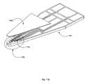
- FIG. 7is a perspective view of a tear film osmolarity measurement system constructed in accordance with one embodiment.
- FIG. 8is a side section of the sample receiving chip showing the opening in the exterior packaging in accordance with one embodiment.
- FIG. 9is a calibration curve relating the sodium content of the sample fluid with electrical conductivity.
- FIG. 10illustrates a hinged base unit of the osmometer that utilizes the sample receiving chips described in FIGS. 1-5 .
- FIG. 11illustrates a probe card configuration for the sample receiving chip and processing unit.
- FIG. 12illustrates an optical osmolarity measurement system constructed in accordance with one embodiment.
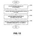
- FIG. 13is a flowchart describing an exemplary osmolarity measurement technique in accordance with one embodiment.
- FIG. 14is a side section of the sample receiving chip showing the opening in the exterior packaging in accordance with another embodiment.
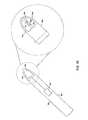
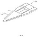
- FIG. 15illustrated an example collection device that can hold the receiving chip of FIG. 14 .
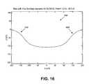
- FIG. 16is a cross sectional view of a channel that can be formed in the receiving chip of FIG. 14 .
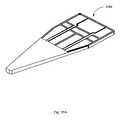
- FIG. 17Aillustrates a microfluidic collection device in accordance with one embodiment.
- FIG. 17Billustrates a more detailed view of the device of FIG. 17A .
- FIG. 17Cillustrates an exploded view of a portion of the device of FIG. 17B .
- FIG. 18is a diagram illustrating another example embodiment of a microfluidic collection device.
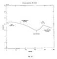
- FIG. 19is a graph illustrating the change in osmolarity over time within a receiving substrate.
- FIG. 20is a graph illustrating the change in osmolarity over time for three different tear collection interfaces.
- Exemplary embodimentsare described for measuring the osmolarity of an aliquot volume of a sample fluid (e.g., tear film, sweat, blood, or other fluids).
- a sample fluide.g., tear film, sweat, blood, or other fluids.
- the exemplary embodimentsare configured to be relatively fast, non-invasive, inexpensive, and easy to use, with minimal risk of injury to the patient. Accurate measurements can be provided with as little as nanoliter volumes of a sample fluid.
- a measuring deviceconfigured in accordance with the embodiments described herein can enable osmolarity measurement with no more than 20 ⁇ L of sample fluid, and typically much smaller volumes can be successfully measured.
- osmolarity measurement accuracyis not compromised by variations in the volume of sample fluid collected, so that osmolarity measurement is substantially independent of collected volume.
- the sample fluidcan include tear film, sweat, blood, urine or other bodily fluids. It should be noted, however, that sample fluid can comprise other fluids, such as milk or other beverages.
- FIG. 1illustrates an exemplary embodiment of an osmolarity chip 100 that can be used to measure the osmolarity of a sample fluid 102 , such as a tear film sample.
- the chip 100includes a substrate 104 with a sample region having sensor electrodes 108 and 109 and circuit connections 110 imprinted on the substrate.
- the electrodes 108 and 109 and circuit connections 110are preferably printed using well-known photolithographic techniques. For example, current techniques enable the electrodes 108 and 109 to have a diameter in the range of approximately one (1) to eighty (80) microns, and spaced apart sufficiently so that no conductive path exists in the absence of sample fluid.
- Currently available techniquescan provide electrodes of less than one micron in diameter, and these are sufficient for a chip constructed in accordance with the embodiments described herein.
- the amount of sample fluid needed for measurementis no more than is necessary to extend from one electrode to the other, thereby providing an operative conductive path.
- the photolithographic scale of the chip 100permits the measurement to be made for aliquot-sized samples in a micro- or nano-scale level. For example, reliable osmolarity measurement can be obtained with a sample volume of less than 20 ⁇ L of tear film. A typical sample volume can be less than one hundred nanoliters (100 nL). It is expected that it will be relatively easy to collect 10 nL of a tear film sample even from patients suffering from dry eye.
- the chip 100can be configured to transfer energy to the sample fluid 102 and enable detection of the sample fluid energy properties.
- a current sourcecan be applied across the electrodes 108 and 109 through the connections 110 .
- the osmolarity of the sample fluidcan be measured by sensing the energy transfer properties of the sample fluid 102 .
- the energy transfer propertiescan include, for example, electrical conductivity, such that the impedance of the sample fluid is measured, given a particular amount of electrical power, e.g., current, that is transferred into the sample through the connections 110 and the electrodes 108 and 109 .
- conductivity of the sample fluidis to be measured, then preferably a sinusoidal signal on the order of ten volts at approximately 10 kHz is applied.
- the real and imaginary parts of the complex impedance of the circuit path from one electrode 108 through the sample fluid 102 to the other electrode 109are measured.
- This electrical signal(hereafter referred to as conductivity) can be directly related to the ion concentration of the sample fluid 102 , and the osmolarity can be determined.
- the osmolaritycan be reliably obtained.
- the impedance valuedoes not depend on the volume of the sample fluid 102 , the osmolarity measurement can be made substantially independent of the sample volume.
- more complex signalscan be applied to the sample fluid the response of which will contribute to a more thorough estimate of osmolarity.
- calibrationcan be achieved by measuring impedances over a range of frequencies. These impedances can be either simultaneously, via combined waveform input and Fourier decomposition, or sequentially measured. The frequency versus impedance data will provide information about the sample and the relative performance of the sample fluid measurement circuit.
- FIG. 2illustrates an alternative embodiment of a sample receiving chip 200 that can be configured to measure osmolarity of a sample fluid 202 , wherein the chip comprises a substrate layer 204 with a sample region 206 comprising an imprinted circuit that includes an array of electrodes 208 .
- the sample region 206has a 5-by-5 array of electrodes that are imprinted with photolithographic techniques, with each electrode 208 having a connection 210 to one side of the substrate 204 . Not all of the electrodes 208 in FIG. 2 are shown with a connection, for simplicity of illustration.
- the electrodecan provide measurements to a separate processing unit, described further below.
- the electrode array of FIG. 2can provide a means to measure the size of the tear droplet 202 by detecting the extent of conducting electrodes 208 to thereby determine the extent of the droplet.
- processing circuitrycan determine the number of electrodes that are conducting, and therefore the number of adjacent electrodes that are covered by the droplet 202 can be determined.
- the planar area of the substrate that is covered by the sample fluidcan thereby be determined. With a known nominal surface tension of the sample fluid, the height of the sample fluid volume over the planar area can also be reliably estimated, and therefore the volume of the droplet 202 can be determined.
- FIG. 3illustrates another alternative embodiment of a sample receiving chip 300 on which a sample fluid 302 is deposited.
- the chipcomprises a substrate layer 304 , wherein a sample region 306 is provided with electrodes 308 that are configured in a plurality of concentric circles.
- the circular arrangement of the FIG. 3 electrodes 308can also provide an estimate of the size of the sample fluid volume 302 because the droplet typically covers a circular or oval area of the sample region 302 .
- Processing circuitrycan be configured to detect the largest (outermost) circle of electrodes that are conducting, and thereby determine a planar area of coverage by the fluid sample.
- the determined planar areacan provide a volume estimate, in conjunction with a known surface tension and corresponding volume height of the sample fluid 302 .
- the electrodes 308can be printed using well-known photolithography techniques that currently permit electrodes to have a diameter in the range of one (1) to eighty (80) microns. This allows the sub-microliter droplet to substantially cover the electrodes.
- the electrodescan be printed over an area sized to receive the sample fluid, generally covering 1 mm 2 to 1 cm 2 .
- the electrodes and connections shown in FIG. 1 , FIG. 2 , and FIG. 3can be imprinted on the respective substrate layers as electrodes with contact pads, using photolithographic techniques.
- the electrodescan be formed with different conductive metalization such as aluminum, platinum, titanium, titanium-tungsten, and other similar material.
- the electrodescan be formed with a dielectric rim to protect field densities at the edges of the electrodes. This can reduce an otherwise unstable electric field at the rim of the electrode.
- FIG. 4 and FIG. 5Top views of the exemplary embodiments of the chips 200 and 300 are illustrated in FIG. 4 and FIG. 5 , respectively.
- the embodimentsshow the detailed layout of the electrodes and the connections, and illustrate how each electrode can be electrically connected for measuring the electrical properties of a sample droplet.
- the layout of the electrodes and the connectionscan be imprinted on the substrate 100 , 200 , 300 using well-known photolithographic techniques.
- FIG. 6is a block diagram of an osmometry system 600 , configured in accordance with an embodiment, showing how information is determined and used in a process that determines osmolarity of a sample fluid.
- the osmometry system 600can include a measurement device 604 and a processing device 606 .
- the measurement devicecan receive a volume of sample fluid from a collection device 608 .
- the collection device 608can comprise, for example, a micropipette or capillary tube.
- the collection device 608can be configured to collect a sample tear film of a patient, such as by using negative pressure from a fixed-volume micropipette or charge attraction from a capillary tube to draw a small tear volume from the vicinity of the ocular surface of a patient.
- the measurement device 604can comprise a system that transfers energy to the fluid in the sample region and detects the imparted energy.
- the measurement device 604can comprise circuitry that provides electrical energy in a specified waveform, such as from a function generator, to the electrical path comprising two electrodes bridged by the sample fluid.
- the processing device 606can be configured to detect the energy imparted to the sample fluid and determine osmolarity.
- the processing devicecan comprise, for example, a system including an RLC multimeter that produces data relating to the reactance of the fluid that forms the conductive path between two electrodes, and including a processor that determines osmolarity through a table look-up scheme. If desired, the processing device can be housed in a base unit that receives one of the chips described above.
- a sample sufficient to provide an osmolarity measurementcan contain less than 20 microliters ( ⁇ L) of fluid.
- a typical sample of tear filmcan be collected by a fluid collector such as a capillary tube, which often contains less than one microliter of tear film.
- Medical professionalswill be familiar with the use of micropipettes and capillary tubes, and will be able to easily collect the small sample volumes described herein, even in the case of dry eye sufferers.
- the collected sample fluidcan be expelled from the collection device 608 to the measurement device 604 .
- the collection devicecan be positioned above the sample region of the chip substrate either manually by a medical professional or by being mechanically guided over the sample region.
- the collection devicee.g., a capillary tube
- the collection deviceis mechanically guided into position with an injection-molded plastic hole in a base unit, or is fitted to a set of clamps with precision screws, e.g., a micromanipulator with needles for microchip interfaces.
- the guideis a computer-guided feedback control circuitry that holds the capillary tube and automatically lowers it into the proper position.
- the electrodes and connections of the chipsmeasure energy properties of the sample fluid, such as conductivity, and enable the measured properties to be received by the processing device 606 .
- the measured energy properties of the sample fluidinclude electrical conductivity and can also include other parameters, such as both parts of the complex impedance of the sample, the variance of the noise in the output signal, and the measurement drift due to resistive heating of the sample fluid.
- the measured energy propertiesare processed in the processing device 606 to provide the osmolarity of the sample.
- the processing device 606comprises a base unit that can accept a chip and can provide electrical connection between the chip and the processing device 606 .
- the base unitcan include a display unit for displaying osmolarity values. It should be noted that the processing device 606 and, in particular, the base unit can be a hand-held unit.
- FIG. 7is a perspective view of a tear film osmolarity measuring system 700 constructed in accordance with one embodiment.
- the exemplary system 700includes a measuring unit 701 that comprises a chip, such as one of the chips described above, and a connector or socket base 710 , which provides the appropriate measurement output.
- the system 700can be configured to determine osmolarity by measuring electrical conductivity of the sample fluid. Therefore, the measurement chip 701 can comprise a integrated circuit (IC) chip with a substrate having a construction similar to that of the chips described above in connection with FIG. 1 through FIG. 5 .
- the chip 701can include a substrate layer with a sample region that is defined by at least two electrodes printed onto the substrate layer.
- the substrate and sample regioncan be encased within an inert package, in a manner that will be known to those skilled in the art.
- the chip 701can be fabricated using conventional semiconductor fabrication techniques into an IC package 707 that includes electrical connection legs 708 that permit electrical signals to be received by the chip 701 and output to be communicated outside of the chip.
- the packaging 707can provide a casing that makes handling of the chip more convenient and helps reduce evaporation of the sample fluid.
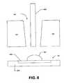
- FIG. 8shows that the measurement chip 701 can be fabricated with an exterior opening hole 720 into which the sample fluid 702 can be inserted.
- the hole 720can be formed in the semiconductor packaging 707 to provide a path through the chip exterior to the substrate 804 and the sample region 806 .
- the collection device, such as a micropipette or capillary tube, 808can be positioned into the hole 720 such that the sample fluid 702 is expelled from the collection device directly onto the sample region 806 of the substrate 804 .
- the hole 720can be sized to receive the tip of the collection device.
- the hole 720forms an opening or funnel that leads from the exterior of the chip onto the sample region 806 of the substrate 804 .
- the sample fluid 702can be expelled from the collection device 808 and can be deposited directly on the sample region 806 of the substrate 804 .
- the sample regioncan be sized to receive the volume of sample fluid from the collection device.
- the electrodescan form a sample region 806 that is generally in a range of approximately 1 mm 2 to 1 cm 2 in area.
- the chip 701can include processing circuitry 704 that comprises, for example, a function generator that generates a signal of a desired waveform, which can be applied to the sample region electrodes of the chip, and a voltage measuring device to measure the root-mean-square (RMS) voltage value that is read from the chip electrodes.
- the function generatorcan be configured to produce high frequency alternating current (AC) to avoid undesirable direct current (DC) effects for the measurement process.
- the voltage measuring devicecan incorporate the functionality of an RLC measuring device.
- the chip 701can incorporate the measurement circuitry as well as the sample region electrodes.
- the processing circuitrycan include a central processing unit (CPU) and associated memory that can store programming instructions (such as firmware) and also can store data. In this way, a single chip can include the electrodes and associated connections for the sample region, and on a separate region of the chip, can also include the measurement circuitry. This configuration can minimize the associated stray resistances of the circuit structures.
- the processing circuitry 704can be configured to apply a signal waveform to the sample region electrodes.
- the processing circuitrycan also receive the energy property signals from the electrodes and determine the osmolarity value of the sample fluid.
- the processing unitcan receive electrical conductivity values from a set of electrode pairs. Those skilled in the art will be familiar with techniques and circuitry for determining the conductivity of a sample fluid that forms a conducting path between two or more electrodes.
- the processing unit 704can be configured to produce signal waveforms at a single frequency, such as 100 kHz and 10 Volts peak-to-peak.
- the processing circuitry 704can then determine the osmolarity value from the sodium content correlated to the electrical conductivity using a calibration curve, such as the curve shown in FIG. 9 .
- the calibration curvecan be constructed as a transfer function between the electrical conductivity (voltage) and the osmolarity value, i.e., the sodium content. It should be noted, however, that other calibration curves can also be constructed to provide transfer functions between other energy properties and the osmolarity value.
- the variance, autocorrelation and drift of the signalcan be included in an osmolarity calculation.
- the osmolarity valuecan also be built upon multi-variable correlation coefficient charts or neural network interpretation so that the osmolarity value can be optimized with an arbitrarily large set of measured variables.
- the processing unit 704can be configured to produce signal waveforms of a predetermined frequency sweep, such as 1 kHz to 100 kHz in 1 kHz increments, and store the conductivity and variance values received from the set of electrode pairs at each frequency.
- the output signal versus frequency curvecan then be used to provide higher order information about the sample, which can be used with the aforementioned transfer functions to produce an ideal osmolarity reading.
- the base socket connector 710can receive the pins 708 of the chip 701 into corresponding sockets 711 .
- the connector 710can supply the requisite electrical power to the processing circuitry 704 and electrodes of the chip.
- the chip 701can include the sample region electrodes and the signal generator and processing circuitry necessary for determining osmolarity, and the output comprising the osmolarity value can be communicated off the chip via the pins 708 through the connector 710 and to a display readout.
- the base connector socket 710can include a Peltier layer 712 located beneath the sockets that receive the pins 708 of the chip 701 .
- a Peltier layercomprises an electrical/ceramic junction such that properly applied current can cool or heat the Peltier layer.
- the sample chip 701can be heated or cooled, thereby further controlling evaporation of the sample fluid. It should be apparent that evaporation of the sample fluid should be carefully controlled, to ensure accurate osmolarity values obtained from the sample fluid.
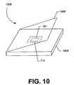
- FIG. 10shows an alternative embodiment of an osmometer in which the chip does not include an on-chip processing unit such as described above, but rather includes limited circuitry comprising primarily the sample region electrodes and interconnections. That is, the processing unit is separately located from the chip and can be provided in, e.g., the base unit.
- FIG. 10shows in detail an osmometer 1000 that includes a base unit 1004 , which houses the base connector 710 , and a hinged cover 1006 that closes over the base connector 710 and a received measurement chip 701 .
- the chipcan be inserted into the socket connector 710 of the base unit 1004 and the hinged cover 1006 can be closed over the chip to reduce the rate of evaporation of the sample fluid.
- the problem with relatively fast evaporation of the sample fluidcan generally be handled in one of two ways.
- One wayis to measure the sample fluid voltage quickly and as soon possible after the droplet is placed on the sample region of the chip.
- Another wayis to enable the measuring unit to measure the rate of evaporation along with the corresponding changes in conductivity values.
- the processing unitcan then post-process the output to estimate the osmolarity value.
- the processingcan be performed in the hardware and/or in software stored in the hardware.
- the processing unitcan incorporate different processing techniques such as using neural networks to collect and learn about characteristics of the fluid samples being measured for osmolarity, as well as temperature variations, volume changes, and other related parameters so that the system can be trained in accordance with neural network techniques to make faster and more accurate osmolarity measurements.
- processing techniquessuch as using neural networks to collect and learn about characteristics of the fluid samples being measured for osmolarity, as well as temperature variations, volume changes, and other related parameters so that the system can be trained in accordance with neural network techniques to make faster and more accurate osmolarity measurements.
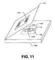
- FIG. 11shows another alternative construction, in which the osmolarity system uses a sample receiving chip 1102 that does not include IC packaging such as shown in FIG. 7 . Rather, the FIG. 11 measurement chip 1102 is configured as a chip with an exposed sample region comprising the electrodes and associated connections, but the processing circuitry is located in the base unit for measuring the energy properties of the sample fluid.
- a connector similar to the connector socket 710can allow transmission of measured energy properties to the processing unit in the base unit.
- a probe card structureis commonly referred to a probe card structure.
- FIG. 11shows a probe card base unit 1100 that can receive a sample chip probe card 1102 that comprises a substrate 1104 with a sample region 1106 on which are formed electrodes 1108 that can be wire bonded to edge connectors 1110 of the probe card.
- a sample chip probe card 1102that comprises a substrate 1104 with a sample region 1106 on which are formed electrodes 1108 that can be wire bonded to edge connectors 1110 of the probe card.
- connecting tines 1114 on the underside of the lidcan be configured to come into mating contact with the edge connectors 1110 .
- the electrodes of the sample region 1106can be coupled to the processing circuitry and measurement can take place.
- the processing circuitry of the probe card embodiment of FIG. 11can, e.g., be configured in either of the configurations described above.
- the processing to apply current to the electrodes and to detect energy properties of the sample fluid and determine osmolaritycan be located on-chip, on the substrate of the probe card 1102 , or the processing circuitry can be located off-chip, in the base unit 1100 .
- the osmometera new measurement chip can be placed into the base unit while the hinged top is open. Upon placement into the base unit, the chip can be powered up and begin monitoring its environment. Recording output signals from the chip at a rate of, for example, 1 kHz, should fully capture the behavior of the system. Placing a sample onto any portion of the electrode array should generate high signal-to-noise increase in conductivity between any pair of electrodes covered by the sample fluid. The processing unit can then recognize the change in conductivity as being directly related to the addition of sample fluid, and can begin conversion of electronic signals into osmolarity data once this type of change is identified. This strategy can occur without intervention by medical professionals. That is, the chip processing can be initiated upon coupling to the base unit and is not necessarily dependent on operating the lid of the base unit or any other user intervention.
- the sample receiving chipcan be disposed of after each use, so that the base unit serves as a platform for interfacing with the disposable measurement chip.
- the base unitcan also include relevant control, communication, and display circuits (not shown), as well as software, or such features can be provided off-chip in the base unit or elsewhere.
- the processing circuitrycan be configured to automatically provide sufficient power to the sample region electrodes to irreversibly oxidize them after a measurement cycle, such that the electrodes are rendered inoperable for any subsequent measurement cycle.
- the userUpon inserted a used chip into the base unit, the user will be given an indication that the electrodes are inoperable. This helps prevent inadvertent multiple use of a sample chip, which can lead to inaccurate osmolarity readings and potentially unsanitary conditions.
- a secondary approach to ensure that a previously used chip is not placed back into the machineincludes encoding serial numbers, or codes directly onto the chip.
- the base unitwill store the used chip numbers in memory and cross-reference them against new chips placed in the base connector. If the base unit finds that the serial number of the used chip is the same as an old chip, then the system will refuse to measure osmolarity until a new chip is inserted. It is important to ensure use of a new chip for each test because proteins adsorb and salt crystals form on the electrodes after evaporation has run its course, which corrupt the integrity of the measuring electrodes.
- the osmolarity of a sample fluidcan be measured optically in an optical measurement system 1200 by using optical indicators 1202 disposed on a measuring region 1212 of the chip substrate 1204 .
- the optical indicators 1202can comprise, for example, nano-scale spheres, also called nanobeads, that are coated with chemicals whose luminescence varies with exposure to sample fluid of varying osmolarity, i.e. ionophores, or plasmon resonances.
- the nanobeads 1202can be deposited on the chip substrate 1204 on top of the electrodes described above for the conductivity-measuring chips.
- the electrodescan be useful, e.g., for determining the volume of the sample fluid, as described above.
- other volume-measuring elementscan be used to determine the volume of the sample fluid.
- the optical chipis produced with inert packaging such as described above in connection with FIG. 7 , including a chip opening hole through which the collection device tip can be inserted. The sample fluid can then be expelled from the collection device and the sample fluid can come into contact with a predetermined, fixed number of the nanobeads per electrode site, which become immersed in the sample fluid.
- the nanobeads 1202When the nanobeads 1202 are illuminated with an optical energy source 1210 , such as a laser, the beads 1202 will fluoresce in accordance with the osmolarity of the sample fluid 1206 .
- the fluorescencecan be detected using a suitable optical detector light receiving device 1208 , such as a conventional charge-coupled device (CCD) array, photodiode, or the like.
- CCDcharge-coupled device
- the resulting output signal of the light receiving arraycan indicate the osmolarity value of the sample fluid.
- the nano-scale beadsare sized such that an aliquot-sized fluid sample 1206 , i.e., no more than 20 microliters of the fluid, will ordinarily produce sufficient fluorescence to provide an output signal that can be detected by the light receiving device 1208 and that can indicate osmolarity of the sample fluid.
- the amount of fluorescencecan be normalized by calculating how many nanobeads were activated by fluid and by measuring which electrode pairs were activated by the sample fluid. This normalization accounts for the sample volume and allows the volume independence feature of the prior embodiment to be retained.
- FIG. 13is a flowchart describing an exemplary osmolarity measurement technique in accordance with one embodiment.
- a body fluid samplesuch as a tear film
- the sampletypically, e.g., contains less than one microliter.
- the collected samplecan be deposited on a sample region of a chip substrate.
- the energy properties of the samplecan then be measured at step 1304 .
- the measured energy propertiescan then be processed, at step 1306 , to determine the osmolarity of the sample. If the chip operates in accordance with electrical conductivity measurement, then the measurement processing at step 1306 can include the “electrode oxidation” operation described above that renders the chip electrodes inoperable for any subsequent measuring cycles.
- the output of the measurement chipcan be a time-varying voltage that is translated into an osmolarity value.
- more information than just the “electrical conductivity” of the samplecan be obtained by measuring the frequency response over a wide range of input signals, which improves the end stage processing.
- the calibrationcan be made over a multiple frequencies, e.g., measure ratio of signals at 10, 20, 30, 40, 50, 100 Hz, etc. to make the measurement process a relative calculation. This makes the chip-to-chip voltage drift small.
- the standard method for macroscale electrode based measurements, i.e., in a pH meter, or microcapillary techniqueis to rely upon known buffers to set up a linear calibration curve. Because photolithography is an extremely reproducible manufacturing technique, when coupled to a frequency sweep, calibration can be performed without operator intervention.
- the processing of the energy propertiescan be performed in a neural network configuration, where the seemingly disparate measured data points obtained from the energy properties can be used to provide more accurate osmolarity reading than from a single energy property measurement. For example, if only the electrical conductivity of the sample is measured, then the calibration curve can be used to simply obtain the osmolarity value corresponding to the conductivity. This osmolarity value, however, generally will not be as accurate as the output of the neural network.
- the neural networkcan be designed to operate on a collection of calibration curves that reflects a substantially optimized transfer function between the energy properties of the sample fluid and the osmolarity.
- the neural networkcan be configured to construct a collection of calibration curves for all variables of interest, such as voltage, evaporation rate, and volume change.
- the neural networkcan also construct or receive as an input a priority list that assigns an importance factor to each variable to indicate the importance of the variable to the final outcome, or the osmolarity value.
- the neural networkcan be configured to construct the calibration curves by training on examples of real data where the final outcome is known a priori. Accordingly, the neural network can be trained to predict the final outcome from the best possible combination of variables.
- This neural network configuration that processes the variables in an efficient combinationcan then be loaded into the processing unit residing, e.g., in the measurement chip 701 or the base unit. Once trained, the neural network can be configured in software and/or hardware.
- the embodiments described above for measuring osmolarityprovide substantial advantage over the conventional osmolarity measuring techniques such as a freezing point depression technique
- the embodiments described hereincan be used to determine osmolarity of a sample in accordance with the freezing point depression technique.
- the exemplary osmometry system 600 of FIG. 6can be used to provide an osmolarity value based on the freezing point depression technique.
- the osmometer of the osmometer systemcan include a cooling device, such as a Peltier cooling device.
- a cooling devicesuch as a Peltier cooling device.
- the Peltier devicecan be disposed on the socket 710 or the chip 701 (see FIG. 7 ) to cool the sample.
- the Peltier cooling devicecan be used to cool the sample fluid to the freezing point of the sample fluid.
- a photo-lithographed metal junction, or p-n junction, known as a thermocouplecan be used to monitor the temperature of aliquot-sized samples.
- thermocouplecan be configured to operate in parallel to the electrode array and Peltier cooling device, where the chip would be cooled below freezing so that the sample becomes a solid. Upon solidification, the electrical conductivity of the sample will drastically change. Because the thermocouple is continually measuring the temperature, the point at which the conductivity spikes can be correlated to the depressed freezing point. Alternatively, the chip can be supercooled immediately prior to sample introduction by the Peltier unit, and then by using the resistive heating inherent to the electrodes, a current can be passed along the solid phase material. Upon melting, the conductivity will again drastically change. In the second measurement technique, it is likely that evaporation will be less of a factor. Thus, the embodiments described herein permit freezing point depression to be performed at significantly smaller volumes of sample fluid than previously possible.
- a hole 720can be used to allow an aliquot volume of the sample fluid 702 , e.g., tear fluid, to be deposited on the sample region 806 .
- the holeis configured such that a collection device, e.g., a capillary 808 , can be used to deposit the sample fluid 702 onto the substrate 806 .
- hole 720can comprise a channel configured to receive the sample fluid 702 through capillary action or negative pressure and cause it to be transferred to the sample region 806 .
- the ability to include such a channelcan be important because it can eliminate a step in the process.
- a two step processis required, wherein the sample fluid 702 is first collected and then deposited onto the sample substrate 806 .
- Such a two step processcan be sufficient for many applications; however, for some applications, e.g., involving tear film, such a two step process may not be sufficient.
- the amount of fluidcan be very small. Accordingly, any loses that occur during the two step process, e.g., due to evaporation, operator error, or the process itself, can cause erroneous results. Accordingly, limiting the chances for such losses can, in certain embodiments, greatly improve the efficiency and accuracy of the test, while simplifying the process.
- the material selection for the packaging 707can play an important role. This is because the ability of the substrate to receive the sample fluid will depend substantially on the material chosen. Thus, the material chosen should allow for the rapid collection and transfer of the sample fluid, e.g., tears. Accordingly, in certain embodiments, an appropriate glass or polymeric material can be chosen to allow for the required rapid collection of the associated sample fluid, while at the same time allowing sufficient manufacturing tolerances so that the IC can be manufactured affordably. For example, materials or surface treatments which decrease the contact angle between the fluid, e.g., tears, and the substrate, preferably below 90°. A more detailed description of the materials and material characteristics that can be used is presented below.
- a hole or a channel 720can become a fluid, or tear collection interface that can be used to receive a sample fluid and transfer it to the sample region 806 .
- the position and geometry of the hole, or the channel 720can vary in order to optimize the collection and measurement of the sample fluid 702 .
- FIG. 14is a diagram illustrating an IC 1400 comprising a sample region 701 , a transducer within the sample region 806 , e.g., electrodes, optical indicators, etc., with the upper strata of the substrate 707 encapsulating the sample region 701 and the lower strata of the substrate 804 .
- a transducerwithin the sample region 806
- the upper strata of the substrate 707encapsulating the sample region 701 and the lower strata of the substrate 804 .
- a channel 1402is formed in the substrate 804 so as to receive tears, e.g., through capillary action.
- a channel 1402can be formed in substrate 804 using various semiconductor manufacturing techniques. As described above, the dimensions and material chosen for the substrate 707 should be selected to ensure rapid collection and transfer of the sample fluid 702 to the sample region 806 .
- Semiconductor processing techniquescan be used to form the channel 1402 residing in the lower strata of the substrate 804 .
- the dimensions and design of the channel 1402should be selected taking into account the manufacturing tolerances of the semiconductor fabrication techniques being used in order to optimize manufacturability.
- the design of the substrateshould also promote tear collection. For instance, traditional glass capillarie, promote tear collection, are often pulled to have a circular cross section, with a diameter of less than 300 micrometers ( ⁇ m) with outer diameters of roughly 1 mm. Such a circular cross section, however, may not be optimal, e.g., for tear collection.
- the channel 1402can be tapered at each end to improve capillary action.
- Thiscan also be achieved using a sandwich construction.
- FIG. 16illustrates a cross sectional view of the channel 1402 in accordance with one embodiment.
- the sloped channel 1402can be a full width half max dimension of less than approximately 200 ⁇ m with a smooth rise at the channel edges 1602 and 1604 .
- the risecan be sinusoidal, sigmoidal or Gaussian.
- These embodimentsprovide drastically shallower channel geometries near the lateral boundary of the channel than the center of the channel. Accordingly, these embodiments should display an increased capillary force at these boundaries, lowering the barrier to capillary action. This provides a substantial benefit over traditional glass capillaries, which feature cylindrical lumens.
- the advantages of these geometriesinclude a lower total volume per length of the microchannel as compared to cylindrical channels, as well as the ability to promote tear collection from the inferior fornix also known as the lower tear lake, which is comprised of the thin meniscus of fluid found at the interface between the lower lid and conjunctiva/cornea.
- These embodimentsallow the surface tension of the tear fluid to bridge the opening of the channel when the tear collection interface is placed in the tear lake; fluid will “jump up” to cover the front of the microchannel.
- these embodimentspromote rotation into the tear lake or resting the tear collection interface on the lower lid which then allows the surface tension to bridge the opening of the lumen.
- the channel 1402can comprise a triangular cross section, a rounded triangle cross section, a half circle cross section, etc.
- the channel 1402can comprise any geometry that promotes fluid collection.
- the substratecan be made rounded or more blunt edged to be more inviting to the patient, and can be made of softer materials, i.e., polymer, to eliminate the chance of injury to the corneal surface.
- the edge of the substratecan be configured to be very thin near the opening of the channel to promote entrance into the tear lake.
- the sample receiving chipcan be placed parallel to the lower lid and then rotated upwards such that the tip of the substrate touches the tear lake.
- the substrateBy fashioning the substrate such that the upper strata covering the channel is minimized in vertical extent, preferably less than approximately 100 ⁇ m, the substrate can be rotated into the tear lake and the lumen of the channel can be completely covered with tear, even if the entirety of the substrate is not wetted.
- the lower strata of the substratecan also be configured for mechanical stability.
- the substratecan also be configured to promote capillary action by having a curved shape having an apex or rounded peak so that the substrate can be moved proximate the eye surface, to pull in tear fluid via capillary action.
- the curved shapecan be configured to minimize the substrate area that comes close to the eye, thereby minimizing any contact with the eye and making it easier for the clinician to get close to the eye and collect the fluid.
- the apex of the curvecan include a feature to promote capillary action and receive the fluid.
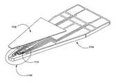
- FIG. 17Bshows that a channel 1402 in the substrate 1704 extends to the edge of the shape, at the apex. Placing the edge of the substrate 1704 proximate the eye surface allows tear fluid to enter the channel 1402 , utilizing a capillary action.
- the channel 1402can be patterned and formed, e.g., using an excimer laser, Nd-YAG laser, or photolithography. The material chosen should then be amenable to the process being used.
- the upper strata of the substrate 707can be formed such that channel 1402 extends to the edge of the substrate.
- the IC 1400can act as the receiving substrate for collecting sample fluid 702 .
- the IC 1400can be used for collection and measurement.
- the IC 1400can comprise a substrate that promotes tear collection.
- the IC 1400can then be interfaced with a processing device, such as device 606 , or in other embodiments, removed from the collection device and interfaced with a processing device.
- FIGS. 17A-17Care diagrams illustrating example embodiments of a sample receiving chip 1700 configured in accordance with one embodiment.
- Integrated circuit 1700can comprise a substrate 1704 , which can include a sample region 1706 , which is shown in finer detail in FIG. 17C .
- the substrate 1704can also include a channel 1402 and electrodes 1710 .
- the upper strata of the substrate 1702can be placed over the lower strata of the substrate 1704 as illustrated in FIG. 17A .
- the channel 1402can extend to the edge of the device 1700 so that the substrate 1704 can receive an aliquot volume of tear and transfer the fluid to the sample region 1706 for measurement.
- the substrate 1704is shaped to promote capillary action from the tear lake as described above.
- the curved edge of the substrate 1704 with the channel 1402 placed perpendicular to the tangent of the curved edgepromotes capillary action within the tear lake with minimal risk to the patient.
- the substrate shapeincludes the curved edge of the substrate 1704 , the appropriate thickness of the strata 1702 and 1704 , and the cross section of the substrate channel 1402 .
- the substrate shapecan also comprise a short, blunt end with channel 1402 perpendicular to the blunt end, and then a linearly receding substrate to form a rectangularly or triangularly receding shape to the substrate 1704 .
- the substrate 1704can also be shaped to promote easy placement near the eye surface, such that the sample receiving chip can be rotated, dipped, pressed, or linearly translated into the tear lake while exposing the channel edge of the substrate to the tear lake.
- the substratecan also be shaped such that it is gently angled to allow the channel to protrude slightly, which allows a thinner extent that makes contact with the tear lake. Since the channel 1402 extends from the sample region 1706 to the edge of the substrate at the rounded edge, the shape of the substrate therefore promotes wicking through capillary action from the edge to the sample region.
- FIG. 17Bis a diagram illustrating a blown up view of area 1706 in FIG. 17A .
- electrodes 1710can be formed over substrate 1704 and in contact with channel 1402 in the sample region.
- FIG. 17Balso more clearly illustrates that channel 1402 extends to the edge of substrate 1402 , and therefore the edge of device 1700 .
- channel 1402does not necessarily need to have the shape and geometry illustrated in FIGS. 17A and 17B .
- the channel 1402can comprise any one of various cross section dimensions and in general, the channel 1402 can comprise any geometry that promotes fluid collection.
- the channel 1402can actually comprise any modification to the surface of substrate 1702 that performs the functions of fluid collection.
- the upper strata of the substrate 1704can be made from a polyester film and attached via a hydrophilic adhesive applied to the bottom side of the substrate 1704 .
- the substrate 1704can be formed from a polycarbonate material or other material compatible with semiconductor fabrication techniques.
- the substrate materialsare preferentially hydrophilic, although a sandwich construction (see FIG. 16 ), where a hydrophilic layer seals a more hydrophobic channel, or hydrophobic sealant of a hydrophilic channel, can also be made to wick tears; glass on polyimide, for instance.
- the class of materials that are preferable for the substrateinclude glass, hydrophilic polymers, silicon, di- and triblock copolymers with amides, amines, sulfates, phosphates or other charged groups.
- polyether block amidesPEBA
- PEEblock-copolyether-esters
- PLApolylactic acid
- PurethanesPU
- PGApolyglycolic acid
- PEpolycaprolactone
- PESpolyethersulfones
- PCpolycarbonate
- a heterogeneous substrateinclude a stratified stack of materials that promote wetting at the tear film interface as well as hydrophilicity throughout the extent of the sample receiving region of the substrate 1402 .
- a hydrophilic pressure sensitive adhesivePSA
- PSAhydrophilic pressure sensitive adhesive
- the strataglass, PSA, polycarbonate
- the upper strata of the substrate 1702can be made of any of the aforementioned materials, which reduce surface tension and promote wetting when placed in contact with the tear film. Similar configurations are possible when making the lower strata of the substrate 1704 hydrophilic through intrinsic material properties or surface treatments.
- a polycarbonate substrate adhered to a hydrophilic PSAcomprised of, e.g., 25 ⁇ m polyester-based hydrophilic adhesive with a, e.g., 100 ⁇ m polyethylene terephthalate (PET) backing can be used.
- a hydrophobic adhesivecan be applied around the outside of the substrate 1714 to eliminate the flow of tears around the exterior of the substrate 1704 .
- FIG. 18Such an embodiment is pictured in FIG. 18 , with the substrate 1704 , the hydrophilic PSA 1702 , and the hydrophobic adhesive 1800 pictured.
- the hydrophobic adhesivecan be comprised of, e.g., beeswax, epoxy resins, or UV curable resins such as urethane (meth) acrylate, and the like.
- the absence of adhesive 1800can allow tears to flow around the exterior of the substrate 1704 and short out the electrodes at the back of PSA 1702 .
- the tear collection interfacecan use the sigmoidal, sinusoidal, or semicircular channel from the PSA backing and hydrophilic PSA adhesive, with the electrodes residing on a flat polycarbonate substrate.
- hydrophilic stratauses identical material on the upper and lower strata but includes a hydrophilic layer in the middle, in direct contact with the channel lumen 1402 .
- Thiscan be a less expensive construction.
- Amphiphilic polymer constructionscan also be used, where hydrophobic side chains are used to bond strata together, while exposing hydrophilic side chains to the channel interior.
- Modifications to one or more of the material layerscan also promote tear collection, such as plasma etching, with nitrogen, oxygen, argon or other gaseous plasmas, acid treatment, exterior coating, increases in surface roughness on the micro- or nanoscale, or comparable methods that reduce contact angle.
- polyelectrolyte coatingscomprising polyethyleneimine, polyaminoalkyl methacrylate, polyvinylpyridine, polylysine, polyacrylic acid, polymethacrylic acid, polysulfonic acid, polyvinyl sulfate, polyacrylamido-2-methyl-1-propanesulfonic acid, and polystyrene sulfonic acid, or other coatings or resin additives known to increase charge density at the interface.
- any materiale.g., polymer, resin, glass, etc., can be used for the substrate 1702 that can promote capillary action at the edge of a the sample receiving chip.
- FIG. 15is a diagram illustrating an example of the collection device 1500 comprising, e.g., a sample receiving chip 1700 in accordance with one embodiment.
- Device 1500can, for example, be sized and shaped somewhat like an pen and can comprise a base portion 1502 and a tip portion 1504 configured to house the sample receiving chip 1700 .
- the tip portion 1504can be configured so that it can be placed in contact with the sample fluid allowing channel 1402 to collect an aliquot volume of the sample fluid for testing.
- Tip portion 1504can be configured so that it can then be removed and interfaced with a processing unit 606 , thereby interfacing device 1700 with processing unit 606 so that the osmolarity of the sample fluid can be measured as described above.
- collection device 1500can include a mechanism (not shown) for decoupling, or ejecting tip portion 1504 .
- Collection device 1500can also be a blunt ended, flat device that seems less needle like to the patient and uses a hinge mechanism to receive device 1700 .
- tip portion 1504 and/or device 1700can then be disposed of and base portion 1502 can be reused with another tip portion 1504 and/or device 1700 . Methods such as those described above can then be used to ensure that a previously used device 1700 is not reused.
- an informational signal 1508can be integrated within collection device 1500 and configured to indicate whether the substrate is properly connected and whether enough sample fluid has been collected.
- fluid filled electrodese.g., the outermost electrodes shown in FIG. 17A , i.e., closest to the channel opening, and closest to the vent hole, can provide a convenient transducer within the substrate.
- a 2-point impedance measurement across these electrodescan distinguish between an open circuit device, and an attached substrate with an empty channel, with typical impedance values changing from around 5 MOhm to around 1 MOhm upon connection of the substrate to the device. Tear collection reduces the impedance between the fluid fill electrodes to generally below 100 kOhm at 100 kHz, providing two clear thresholds for hardware to provide user feedback.
- Indicator 1508can also include, or be coupled with an auditory indicator to indicate whether enough sample fluid has been collected.
- a Light Emitting Diode (LED) or other indicatorcan be activated when enough sample fluid is present.
- a beep or other tone in conjunction with the visible feedbackcan be used as parallel indication of filling the channel.
- one indicatorsuch as a red LED
- a second indicatorsuch as a green LED can be used to indicate when enough sample fluid is present.
- the red LEDcan be active until enough sample fluid is present at which point the red LED is turned off and the green LED is activated.
- audible indicatorscan be used.
- displayssuch as LED or Liquid Crystal Displays (LCDs) can be used to convey the sample fluid status.
- the embodiments described aboveare generally related to systems and methods for detecting, or determining osmolarity for a fluid sample; however, it will be appreciated that the systems and methods described herein are not limited to the detection/determination of osmolarity. Rather, the systems and methods described herein can be employed to detect other parameters associated with a sample fluid. For example, in the embodiments described below, the systems and methods described herein can be used to detect any analyte of interest (e.g., a biomarker) contained in the fluid sample. For example, the systems and methods described herein can be used to detect analytes such as proteins, peptides, and oligonucleotides.
- analytessuch as proteins, peptides, and oligonucleotides.
- the systems and methods described hereincan be used to detect, or measure any metabolites (e.g., glucose) or proteins (e.g., matrix metalloproteinases (e.g., MMP-9), proline-rich proteins (e.g., proline-rich protein BstNI subfamily 1 (or, PRB1); proline-rich protein BstNI subfamily 3 (or, PRB3); proline-rich protein BstNI subfamily 4 (or, PRB4); proline rich, lacrimal 1 (PROL1); proline rich 4 (lacrimal) (or, PRR4, nasopharyngeal carcinoma-associated proline rich protein)), alpha-1-antitrypsin (or, Alpha 1-Antitrypsin, ⁇ 1-antitrypsin, serum trypsin inhibitor), calgranulin, immunoglobulins, (e.g., IgE, IgM, and IgA), mucins (e.g., MUC5AC, MUC5AC,
- electrical signals produced by electrodes in sample region 806are used to detect analytes (e.g., metabolites (e.g., glucose) or proteins (e.g., matrix metalloproteinases (e.g., MMP-9), proline-rich proteins (e.g., proline-rich protein BstNI subfamily 1 (or, PRB1); proline-rich protein BstNI subfamily 3 (or, PRB3); proline-rich protein BstNI subfamily 4 (or, PRB4); proline rich, lacrimal 1 (PROL1); proline rich 4 (lacrimal) (or, PRR4, nasopharyngeal carcinoma-associated proline rich protein)), alpha-1-antitrypsin (or, Alpha 1-Antitrypsin, ⁇ 1-antitrypsin, serum trypsin inhibitor), calgranulin, immunoglobulins, (e.g., IgE, IgM, and IgA), mucins (e.
- optical detection methodsare used to detect analytes of interest (e.g., metabolites (e.g., glucose) or proteins (e.g., matrix metalloproteinases (e.g., MMP-9), proline-rich proteins (e.g., proline-rich protein BstNI subfamily 1 (or, PRB1); proline-rich protein BstNI subfamily 3 (or, PRB3); proline-rich protein BstNI subfamily 4 (or, PRB4); proline rich, lacrimal 1 (PROL1); proline rich 4 (lacrimal) (or, PRR4, nasopharyngeal carcinoma-associated proline rich protein)), alpha-1-antitrypsin (or, Alpha 1-Antitrypsin, ⁇ 1-antitrypsin, serum trypsin inhibitor), calgranulin, immunoglobulins, (e.g., IgE, IgM, and IgA), mucins (e.g., MUC5
- any of suitable transduction techniquemay be used to detect or measure an analyte of interest (e.g., metabolites (e.g., glucose) or proteins (e.g., matrix metalloproteinases (e.g., MMP-9), proline-rich proteins (e.g., proline-rich protein BstNI subfamily 1 (or, PRB1); proline-rich protein BstNI subfamily 3 (or, PRB3); proline-rich protein BstNI subfamily 4 (or, PRB4); proline rich, lacrimal 1 (PROL1); proline rich 4 (lacrimal) (or, PRR4, nasopharyngeal carcinoma-associated proline rich protein)), alpha-1-antitrypsin (or, Alpha 1-Antitrypsin, ⁇ 1-antitrypsin, serum trypsin inhibitor), calgranulin, immunoglobulins, (e.g., IgE, IgM, and IgA), mucins (e.
- the transduction technique used to detect an analyte in a fluid sample incident on sample region 806is selected from: electrochemical, optoentropic, optomechanical, fluorescent, chemiluminescent, chromataographic, surface plasmon resonant (SPR) transduction methods.
- the transduction technique used to detect glucose in a fluid sample incident on sample region 806is selected from: electrochemical, optoentropic, optomechanical, fluorescent, chemiluminescent, chromataographic, surface plasmon resonant (SPR) transduction methods.
- nanobeadsare used to detect an analyte of interest (e.g., metabolites (e.g., glucose) or proteins (e.g., matrix metalloproteinases (e.g., MMP-), proline-rich proteins (e.g., proline-rich protein BstNI subfamily 1 (or, PRB1); proline-rich protein BstNI subfamily 3 (or, PRB3); proline-rich protein BstNI subfamily 4 (or, PRB4); proline rich, lacrimal 1 (PROL1); proline rich 4 (lacrimal) (or, PRR4, nasopharyngeal carcinoma-associated proline rich protein)), alpha-1-antitrypsin (or, Alpha 1-Antitrypsin, ⁇ 1-antitrypsin, serum trypsin inhibitor), calgranulin, immunoglobulins, (e.g., IgE, IgM, and IgA), mucins (e.g.
- the nanobeadsare coated with a chemical that changes fluorescence based on the amount of the target analyte (e.g., metabolites (e.g., glucose) or proteins (e.g., matrix metalloproteinases (e.g., MMP-9), proline-rich proteins (e.g., proline-rich protein BstNI subfamily 1 (or, PRB1); proline-rich protein BstNI subfamily 3 (or, PRB3); proline-rich protein BstNI subfamily 4 (or, PRB4); proline rich, lacrimal 1 (PROL1); proline rich 4 (lacrimal) (or, PRR4, nasopharyngeal carcinoma-associated proline rich protein)), alpha-1-antitrypsin (or, Alpha 1-Antitrypsin, ⁇ 1-antitrypsin, serum trypsin inhibitor), calgranulin, immunoglobulins, (e.g., IgE, IgM, and
- the nanobeadsare coated with a chemical that changes fluorescence based on the amount of glucose in a sample fluid.
- the nanobeadsare coated with a biological substance that binds to the analyte of interest (e.g., metabolites (e.g., glucose) or proteins (e.g., matrix metalloproteinases (e.g., MMP-9), proline-rich proteins (e.g., proline-rich protein BstNI subfamily 1 (or, PRB1); proline-rich protein BstNI subfamily 3 (or, PRB3); proline-rich protein BstNI subfamily 4 (or, PRB4); proline rich, lacrimal 1 (PROL1); proline rich 4 (lacrimal) (or, PRR4, nasopharyngeal carcinoma-associated proline rich protein)), alpha-1-antitrypsin (or, Alpha 1-Antitrypsin, ⁇ 1-antitrypsin, serum tryp
- lightis used to illuminate the beads and detect the presence of the analyte (e.g., metabolites (e.g., glucose) or proteins (e.g., matrix metalloproteinases (e.g., MMP-9), proline-rich proteins (e.g., proline-rich protein BstNI subfamily 1 (or, PRB1); proline-rich protein BstNI subfamily 3 (or, PRB3); proline-rich protein BstNI subfamily 4 (or, PRB4); proline rich, lacrimal 1 (PROL1); proline rich 4 (lacrimal) (or, PRR4, nasopharyngeal carcinoma-associated proline rich protein)), alpha-1-antitrypsin (or, Alpha 1-Antitrypsin, ⁇ 1-antitrypsin, serum trypsin inhibitor), calgranulin, immunoglobulins, (e.g., IgE, IgM, and IgA), mucins (e.g., metabol
- transduction mechanismssuch as electrochemical including potentiometric, amperometric, capacitance, and impedance spectroscopy, cyclic voltammery, pulse voltammery, etc., transduction methods may be used in conjunction with the electrodes within the sample region.
- nzyme modified electrochemical redox reactionssuch as horseradish peroxidase labels, gold nanoparticle labels, and other electrochemically active labels are within the transduction mechanism.
- Further embodimentsinclude measuring changes in potentiometric conductive polymers, such as polypyrrole, after exposure to tear fluid.
- conductive polymers and the other transduction systems described hereinare incorporated directly into the sample region of the substrate in order to mitigate the effects of evaporation on an open system.
- mitigation of evaporation during measurement of analytes of intereste.g., metabolites (e.g., glucose) or proteins (e.g., matrix metalloproteinases (e.g., MMP-9), proline-rich proteins (e.g., proline-rich protein BstNI subfamily 1 (or, PRB1); proline-rich protein BstNI subfamily 3 (or, PRB3); proline-rich protein BstNI subfamily 4 (or, PRB4); proline rich, lacrimal 1 (PROL1); proline rich 4 (lacrimal) (or, PRR4, nasopharyngeal carcinoma-associated proline rich protein)), alpha-1-antitrypsin (or, Alpha 1-Antitrypsin, ⁇ 1-antitrypsin, serum trypsin inhibitor), calgranulin, immunoglobulins, (e.g., IgE, IgM, and IgA), mucins (e.g., MMP-9), pro
- the capcomprises an interference fitted plastic, or gasketed seal, much like a normal pen cap, which slides over both the vent hole of the substrate and channel opening 1402 .
- the cap designallows for a very small displacement of air, as the movement of fluid within the channel is undesired. For example, vent holes that are carved along the outside of the pen cap could terminate just prior to sealing such that sufficient mechanical stability is achieved while minimizing the air displacement.
- mitigation of evaporation during measurement of analytes of intereste.g., metabolites (e.g., glucose) or proteins (e.g., matrix metalloproteinases (e.g., MMP-9), proline-rich proteins (e.g., proline-rich protein BstNI subfamily 1 (or, PRB1); proline-rich protein BstNI subfamily 3 (or, PRB3); proline-rich protein BstNI subfamily 4 (or, PRB4); proline rich, lacrimal 1 (PROL1); proline rich 4 (lacrimal) (or, PRR4, nasopharyngeal carcinoma-associated proline rich protein)), alpha-1-antitrypsin (or, Alpha 1-Antitrypsin, ⁇ 1-antitrypsin, serum trypsin inhibitor), calgranulin, immunoglobulins, (e.g., IgE, IgM, and IgA), mucins (e.g., MMP-9), pro
- FIG. 19demonstrates a typical change in osmolarity over time within a receiving substrate as measured by a four-point impedance method.
- the initial transientwithin the first 10 seconds, sees the impedance increase as a result of the equilibration (slowing) of the tear fluid being pulled into the capillary channel.
- a small volume of residual tearremains outside of the substrate immediately following tear collection. As these tears are exposed to the environment with a large surface area, these tears are of higher osmolarity than the tears that originally populated the channel.
- Continual capillary actiondraws this higher concentration fluid into the channel and mixes the fluids, gradually decreasing the impedance of the fluid as the concentration changes.
- the flow of the fluidbegins to slow again, e.g., about 140 seconds in, increasing the impedance.
- the vent holecontains a reservoir of fluid, it is typically hypoosmolar at the base of the column, the fluid unexposed to the air. Once the vent starts sourcing the fluid back into the channel, the hypoosmolar fluid lowers the concentration of the fluid and increases the impedance. After all sources have been emptied, the impedance drops in a near-linear fashion, indicative of steady evaporation.
- FIG. 20exhibits these dynamics across three different tear collection interface geometries.
- a 100 ⁇ m wide, by 75 ⁇ m deep, by 2.5 mm long sinusoidal channel constructed from polyester PSA thermally bonded to polycarbonatehas the greatest percent change in osmolarity during incubation, with about a 34% change over 150 seconds.
- a 300 ⁇ m wide, by 75 ⁇ m deep, by 5 mm long channelsees only a few percent change over the time of incubation.
- the transduction of analytes of interestis normalized against these dynamics.
- an instantaneous potentiometric measurementcan be normalized against the ratio of the initial steady state value, e.g., around 10 seconds, vs. the instantaneous impedance at the time of measurement as one of the methods of normalization.
- Integral amperometric methodscan be normalized against the average of the displacement of the impedance curve. In general, many normalizations can be made to adjust the reported level of analyte of interest in order to improve the standard of care.
- biomarker normalizationis performed against a measured osmolarity in order to remove the impact of tear sampling and patient-specific tear homeostasis from the interpretation of biomarker concentration in tears.
- the normalizationprovides an Adjusted Tear Biomarker Level.
- an Adjusted Tear Biomarker Levelis calculated to compensate for the possibility of patient hyperosmolarity or dilution introduced by tear sampling. That is, the Adjusted Tear Biomarker Level can compensate and correct for patient-specific tear homeostasis and for clinician-induced tear sampling variance in connection with obtaining the sample fluid.
- the biomarker concentrationis not normalized against a measured osmolarity in order to remove the impact of tear sampling and patient-specific tear homeostasis from the interpretation of biomarker concentration in tears.
- Adjusted Tear Biomarker Level(300 mOsm/L*Measured Tear Biomarker Level)/(Measured Tear Osmolarity Level)
- Adjusted Tear Biomarker Level(300 mOsm/L*Measured Tear Biomarker Level)/(Measured Tear Osmolarity Level)
- the defined value of 300 mOsm/Lcan be substituted for any of the appropriate range of tear osmolarity levels.
- the basal level of tear osmolaritycan be measured for a specific patient at the beginning of a study, at pretreatment, at an early age, or prior to surgery in order to establish a personalized baseline level of tear homeostasis. Following the passage of time, a pharmaceutical administration, or surgery, the personalized baseline level can be substituted for the defined 300 mOsm/L.
- Open Loop Adjusted Tear Biomarker LevelMeasured Tear Biomarker Level/(Measured Tear Osmolarity Level)
- Adjusted Tear Biomarker Levelis expressed in units identical to the Measured Tear Biomarker Level. Open loop adjustment would result in a Biomarker Level/mOsms/L, which could be a more difficult parameter for clinicians to interpret, especially if the analyte of interest is commonly known to have a range in unnormalized units.
- Similar Adjusted Tear Biomarker Levelscan be performed using linear, logarithmic, exponential, or though the use of calibration curve adjustments.
- the systems and methods described hereincan be used for any fluid, e.g., serum, and to detect a variety of parameters including osmolarity and the presence, or amount of an analyte of interest. All modifications, variations, or equivalent arrangements and implementations that are within the scope of the attached claims should therefore be considered within the scope of the invention.
Landscapes
- Health & Medical Sciences (AREA)
- Chemical & Material Sciences (AREA)
- Life Sciences & Earth Sciences (AREA)
- Physics & Mathematics (AREA)
- Engineering & Computer Science (AREA)
- General Health & Medical Sciences (AREA)
- Analytical Chemistry (AREA)
- Immunology (AREA)
- Biochemistry (AREA)
- General Physics & Mathematics (AREA)
- Pathology (AREA)
- Biomedical Technology (AREA)
- Hematology (AREA)
- Molecular Biology (AREA)
- Chemical Kinetics & Catalysis (AREA)
- Organic Chemistry (AREA)
- Proteomics, Peptides & Aminoacids (AREA)
- Urology & Nephrology (AREA)
- Biophysics (AREA)
- Wood Science & Technology (AREA)
- Food Science & Technology (AREA)
- Medicinal Chemistry (AREA)
- Zoology (AREA)
- Microbiology (AREA)
- Biotechnology (AREA)
- Clinical Laboratory Science (AREA)
- Dispersion Chemistry (AREA)
- Plasma & Fusion (AREA)
- Bioinformatics & Cheminformatics (AREA)
- Genetics & Genomics (AREA)
- General Engineering & Computer Science (AREA)
- Optics & Photonics (AREA)
- Nuclear Medicine, Radiotherapy & Molecular Imaging (AREA)
- Cell Biology (AREA)
- Investigating Or Analyzing Materials By The Use Of Electric Means (AREA)
Abstract
Description
Adjusted Tear Biomarker Level=(300 mOsm/L*Measured Tear Biomarker Level)/(Measured Tear Osmolarity Level)
The defined value of 300 mOsm/L can be substituted for any of the appropriate range of tear osmolarity levels. In another embodiment, the basal level of tear osmolarity can be measured for a specific patient at the beginning of a study, at pretreatment, at an early age, or prior to surgery in order to establish a personalized baseline level of tear homeostasis. Following the passage of time, a pharmaceutical administration, or surgery, the personalized baseline level can be substituted for the defined 300 mOsm/L.
Open Loop Adjusted Tear Biomarker Level=Measured Tear Biomarker Level/(Measured Tear Osmolarity Level)
Linear Adjusted Tear Biomarker Level=Badj=Bm*(1+(Alpha*(Osmm−300 mOsms/L)))
where Badjis the Linear Adjusted Tear Biomarker Level, Bmis the measured biomarker level, Alpha is the linear correction factor, and Osmmis the measured osmolarity. Both the Alpha and the 300 mOsms/L point can be altered to fit the specific biomarker curve.
Claims (33)
Priority Applications (1)
| Application Number | Priority Date | Filing Date | Title |
|---|---|---|---|
| US13/299,277US8628731B2 (en) | 2003-03-25 | 2011-11-17 | Systems and methods for collecting tear film and measuring tear film osmolarity |
Applications Claiming Priority (5)
| Application Number | Priority Date | Filing Date | Title |
|---|---|---|---|
| US10/400,617US7017394B2 (en) | 2002-08-06 | 2003-03-25 | Tear film osmometry |
| US86954306P | 2006-12-11 | 2006-12-11 | |
| US12/001,243US7810380B2 (en) | 2003-03-25 | 2007-12-11 | Systems and methods for collecting tear film and measuring tear film osmolarity |
| US12/874,088US8713997B2 (en) | 2003-03-25 | 2010-09-01 | Systems and methods for collecting tear film and measuring tear film osmolarity |
| US13/299,277US8628731B2 (en) | 2003-03-25 | 2011-11-17 | Systems and methods for collecting tear film and measuring tear film osmolarity |
Related Parent Applications (1)
| Application Number | Title | Priority Date | Filing Date |
|---|---|---|---|
| US12/874,088Continuation-In-PartUS8713997B2 (en) | 2003-03-25 | 2010-09-01 | Systems and methods for collecting tear film and measuring tear film osmolarity |
Publications (2)
| Publication Number | Publication Date |
|---|---|
| US20120090388A1 US20120090388A1 (en) | 2012-04-19 |
| US8628731B2true US8628731B2 (en) | 2014-01-14 |
Family
ID=46329919
Family Applications (7)
| Application Number | Title | Priority Date | Filing Date |
|---|---|---|---|
| US12/001,243Active2029-01-25US7810380B2 (en) | 2002-08-06 | 2007-12-11 | Systems and methods for collecting tear film and measuring tear film osmolarity |
| US12/874,088Active2029-07-05US8713997B2 (en) | 2003-03-25 | 2010-09-01 | Systems and methods for collecting tear film and measuring tear film osmolarity |
| US13/299,277Expired - LifetimeUS8628731B2 (en) | 2003-03-25 | 2011-11-17 | Systems and methods for collecting tear film and measuring tear film osmolarity |
| US13/779,597AbandonedUS20130175185A1 (en) | 2006-12-11 | 2013-02-27 | Systems and methods for collecting tear film and measuring tear film osmolarity |
| US13/802,534ActiveUS8627712B2 (en) | 2006-12-11 | 2013-03-13 | Systems and methods for collecting tear film and measuring tear film osmolarity |
| US14/852,108ActiveUS9335243B2 (en) | 2006-12-11 | 2015-09-11 | Systems and methods for collecting tear film and measuring tear film osmolarity |
| US15/362,283AbandonedUS20170108423A1 (en) | 2006-12-11 | 2016-11-28 | Systems and methods for collecting tear film and measuring tear film osmolarity |
Family Applications Before (2)
| Application Number | Title | Priority Date | Filing Date |
|---|---|---|---|
| US12/001,243Active2029-01-25US7810380B2 (en) | 2002-08-06 | 2007-12-11 | Systems and methods for collecting tear film and measuring tear film osmolarity |
| US12/874,088Active2029-07-05US8713997B2 (en) | 2003-03-25 | 2010-09-01 | Systems and methods for collecting tear film and measuring tear film osmolarity |
Family Applications After (4)
| Application Number | Title | Priority Date | Filing Date |
|---|---|---|---|
| US13/779,597AbandonedUS20130175185A1 (en) | 2006-12-11 | 2013-02-27 | Systems and methods for collecting tear film and measuring tear film osmolarity |
| US13/802,534ActiveUS8627712B2 (en) | 2006-12-11 | 2013-03-13 | Systems and methods for collecting tear film and measuring tear film osmolarity |
| US14/852,108ActiveUS9335243B2 (en) | 2006-12-11 | 2015-09-11 | Systems and methods for collecting tear film and measuring tear film osmolarity |
| US15/362,283AbandonedUS20170108423A1 (en) | 2006-12-11 | 2016-11-28 | Systems and methods for collecting tear film and measuring tear film osmolarity |
Country Status (1)
| Country | Link |
|---|---|
| US (7) | US7810380B2 (en) |
Cited By (3)
| Publication number | Priority date | Publication date | Assignee | Title |
|---|---|---|---|---|
| US20130233061A1 (en)* | 2002-08-06 | 2013-09-12 | The Regents Of The University Of California | Biomarker normalization |
| WO2016049221A1 (en)* | 2014-09-23 | 2016-03-31 | Tearlab Research, Inc. | Systems and methods for integration of microfluidic tear collection and lateral flow analysis of analytes of interest |
| US9335243B2 (en) | 2006-12-11 | 2016-05-10 | Tearlab Research, Inc. | Systems and methods for collecting tear film and measuring tear film osmolarity |
Families Citing this family (12)
| Publication number | Priority date | Publication date | Assignee | Title |
|---|---|---|---|---|
| EP2510351A4 (en)* | 2009-12-07 | 2018-01-10 | Yale University | Label-free cellular manipulation and sorting via biocompatible ferrofluids |
| ES2568787T3 (en) | 2011-10-17 | 2016-05-04 | Opia Technologies | Device and procedure for sampling tear fluid |
| WO2014144782A2 (en) | 2013-03-15 | 2014-09-18 | Ancera, Inc. | Systems and methods for active particle separation |
| US20160299132A1 (en) | 2013-03-15 | 2016-10-13 | Ancera, Inc. | Systems and methods for bead-based assays in ferrofluids |
| US10004433B2 (en) | 2014-07-07 | 2018-06-26 | Verily Life Sciences Llc | Electrochemical sensor chip |
| US9976974B2 (en)* | 2015-01-27 | 2018-05-22 | University Of Utah Research Foundation | Osmolarity-responsive hydrogel sensors and method of use |
| US11285490B2 (en) | 2015-06-26 | 2022-03-29 | Ancera, Llc | Background defocusing and clearing in ferrofluid-based capture assays |
| USD795839S1 (en)* | 2016-02-09 | 2017-08-29 | Lina Zhang | Electronics case |
| JP6735500B2 (en)* | 2016-04-21 | 2020-08-05 | パナソニックIpマネジメント株式会社 | Evaluation method of resin impregnating ability of glass fiber for resin molding |
| CN109269842B (en)* | 2018-11-07 | 2023-10-27 | 中国矿业大学(北京) | Sampling device for obtaining cementing filling slurry at different levels and its working method |
| US20220218514A1 (en)* | 2019-05-14 | 2022-07-14 | Verily Life Sciences Llc | Ophthalmic devices, systems and methods for treating dry eye |
| AT523565A1 (en)* | 2020-03-05 | 2021-09-15 | B & R Ind Automation Gmbh | Transport device |
Citations (120)
| Publication number | Priority date | Publication date | Assignee | Title |
|---|---|---|---|---|
| US4028931A (en) | 1976-02-13 | 1977-06-14 | Cardio Pulminary Laboratory Research Foundation | Osmotic pressure sensing head |
| US4123701A (en) | 1976-07-01 | 1978-10-31 | United States Surgical Corporation | Disposable sample card having a well with electrodes for testing a liquid sample |
| US4134730A (en) | 1977-09-20 | 1979-01-16 | Quame Babington A | Spotting systems and methods pertaining thereto |
| US4150564A (en) | 1978-04-10 | 1979-04-24 | Wescor, Inc. | Osmometer for colloid osmometry |
| US4245495A (en) | 1977-12-27 | 1981-01-20 | Hokkaido University | Needle-type colloid osmometer |
| US4269197A (en) | 1979-04-05 | 1981-05-26 | Gilbard Jeffrey P | Method of measuring tear osmolarity and apparatus therefor |
| US4301412A (en) | 1979-10-29 | 1981-11-17 | United States Surgical Corporation | Liquid conductivity measuring system and sample cards therefor |
| US4305823A (en) | 1978-02-21 | 1981-12-15 | Ciba-Geigy Corporation | Semipermeable membranes from modified polymers |
| US4448207A (en) | 1981-11-03 | 1984-05-15 | Vital Metrics, Inc. | Medical fluid measuring system |
| US4449538A (en) | 1982-01-25 | 1984-05-22 | John Corbitt | Medical-electronic body fluid accounting system |
| US4455864A (en) | 1981-03-17 | 1984-06-26 | Franz Wallner | Membrane osmometer |
| US4475556A (en) | 1983-01-03 | 1984-10-09 | Reiff Theodore R | Rapid measurement of colloid osmotic equilibrium pressure |
| DE3414866A1 (en) | 1984-04-19 | 1985-10-31 | Karl Dipl.-Phys. 8011 Pliening Schickle | Method and device for measuring the osmolarity of liquid samples |
| US4603699A (en) | 1984-11-20 | 1986-08-05 | Himpens Jacques M | Apparatus and method for measuring osmotic pressure in situ |
| US4706495A (en) | 1984-10-31 | 1987-11-17 | Kernforschungsanlage Julich Gesellschaft Mit Beschrankter Haftung | Method and apparatus for the determination of substances dissolved in a solvent |
| US4787963A (en) | 1987-05-04 | 1988-11-29 | Syntro Corporation | Method and means for annealing complementary nucleic acid molecules at an accelerated rate |
| US4951683A (en) | 1989-01-19 | 1990-08-28 | Davis Jeffrey P | Device for detecting keratoconjunctivitis sicca |
| EP0391674A2 (en) | 1989-04-05 | 1990-10-10 | New York University | A method for characterising particles |
| US4996993A (en) | 1988-12-07 | 1991-03-05 | York Kenneth K | In vivo osmometer |
| US5005403A (en) | 1988-07-25 | 1991-04-09 | Ernst Steudle | Process and apparatus for the determination of the concentration of a substance dissolved in a solvent by means of an osmometer |
| US5112622A (en) | 1990-01-19 | 1992-05-12 | Kopp Klaus F | Intravenous solutions for influencing renal function and for maintenance therapy |
| US5132012A (en) | 1988-06-24 | 1992-07-21 | Hitachi, Ltd. | Liquid chromatograph |
| US5143080A (en) | 1988-12-07 | 1992-09-01 | York Kenneth K | In vivo osmometer |
| US5211055A (en) | 1987-10-27 | 1993-05-18 | Kernforschungsanlage Lulich Gesellschaft mit beschrankter Haftung | Apparatus for the selective determination of the concentration of a substance dissolved in a solvent |
| US5218088A (en) | 1989-11-02 | 1993-06-08 | Purdue Research Foundation | Process for preparing dithiophosphate oligonucleotide analogs via nucleoside thiophosphoramidite intermediates |
| US5221457A (en) | 1991-09-23 | 1993-06-22 | Porton Diagnostics, Inc. | System for analyzing ion levels in fluids |
| US5230864A (en) | 1991-04-10 | 1993-07-27 | Eastman Kodak Company | Gravity assisted collection device |
| EP0571066A2 (en) | 1992-05-22 | 1993-11-24 | Puritan-Bennett Corporation | Storage and calibration solution for multiparameter intravascular blood gas sensor device |
| US5388449A (en) | 1993-07-06 | 1995-02-14 | Leveen; Harry H. | Osmolarity sensor |
| US5461699A (en) | 1993-10-25 | 1995-10-24 | International Business Machines Corporation | Forecasting using a neural network and a statistical forecast |
| US5522805A (en) | 1994-05-03 | 1996-06-04 | Aquintel, Inc. | Surgical fluid monitor |
| US5571568A (en) | 1989-06-15 | 1996-11-05 | Biocircuits Corporation | Multilayered bioelectronic sensors |
| US5591636A (en) | 1993-10-18 | 1997-01-07 | Precision Instrument Design | Membrane holder |
| US5605662A (en) | 1993-11-01 | 1997-02-25 | Nanogen, Inc. | Active programmable electronic devices for molecular biological analysis and diagnostics |
| US5620584A (en) | 1994-03-14 | 1997-04-15 | Studiengesellschaft Kohle Mbh | Electrochemical reduction of metal salts as a method of preparing highly dispersed metal colloids and substrate fixed metal clusters by electrochemical reduction of metal salts |
| US5665904A (en) | 1994-03-08 | 1997-09-09 | Forschungszentrum Julich Gmbh | Osmometric device and process for determining the analyte content of a solution of mixed substances |
| US5739376A (en) | 1993-04-24 | 1998-04-14 | Hoechst Aktiengesellschaft | Fullerene derivatives, methods of preparing them and their use |
| US5766435A (en) | 1993-01-26 | 1998-06-16 | Bio-Rad Laboratories, Inc. | Concentration of biological samples on a microliter scale and analysis by capillary electrophoresis |
| US5772585A (en) | 1996-08-30 | 1998-06-30 | Emc, Inc | System and method for managing patient medical records |
| US5810725A (en) | 1993-04-16 | 1998-09-22 | Matsushita Electric Industrial Co., Ltd. | Planar electrode |
| US5821399A (en) | 1993-07-16 | 1998-10-13 | I-Stat Corporation | Automatic test parameters compensation of a real time fluid analysis sensing device |
| US5849486A (en) | 1993-11-01 | 1998-12-15 | Nanogen, Inc. | Methods for hybridization analysis utilizing electrically controlled hybridization |
| US5849208A (en) | 1995-09-07 | 1998-12-15 | Microfab Technoologies, Inc. | Making apparatus for conducting biochemical analyses |
| US5851489A (en) | 1994-05-17 | 1998-12-22 | Micronas Intermetall Gmbh | Specimen slide for a microscope |
| US5869231A (en) | 1993-10-21 | 1999-02-09 | Behring Diagnostics Gmbh | Method for reproducibly determining the components of lacrimal fluid |
| US5959671A (en) | 1995-09-14 | 1999-09-28 | Canon Kabushiki Kaisha | Adapter system for connection and disconnection of peripheral equipment with an electric apparatus and having a cam system |
| US5965631A (en) | 1994-09-06 | 1999-10-12 | Ciba Vision Corporation | Extended wear ophthalmic lens |
| US5994410A (en) | 1995-10-26 | 1999-11-30 | National Science Council | Therapeutic use of water-soluble fullerene derivatives |
| US5997817A (en) | 1997-12-05 | 1999-12-07 | Roche Diagnostics Corporation | Electrochemical biosensor test strip |
| US6038554A (en) | 1995-09-19 | 2000-03-14 | Vig; Tommy | Non-Subjective Valuing© the computer aided calculation, appraisal and valuation of anything and anybody |
| US6048690A (en) | 1991-11-07 | 2000-04-11 | Nanogen, Inc. | Methods for electronic fluorescent perturbation for analysis and electronic perturbation catalysis for synthesis |
| US6090251A (en) | 1997-06-06 | 2000-07-18 | Caliper Technologies, Inc. | Microfabricated structures for facilitating fluid introduction into microfluidic devices |
| US6120460A (en) | 1996-09-04 | 2000-09-19 | Abreu; Marcio Marc | Method and apparatus for signal acquisition, processing and transmission for evaluation of bodily functions |
| US6162926A (en) | 1995-07-31 | 2000-12-19 | Sphere Biosystems, Inc. | Multi-substituted fullerenes and methods for their preparation and characterization |
| US6183714B1 (en) | 1995-09-08 | 2001-02-06 | Rice University | Method of making ropes of single-wall carbon nanotubes |
| US6224550B1 (en) | 1996-12-23 | 2001-05-01 | Lifecare A.S. | Method for monitoring the level of an osmotically active component in body fluid and device for carrying out said method |
| US6344272B1 (en) | 1997-03-12 | 2002-02-05 | Wm. Marsh Rice University | Metal nanoshells |
| US20020031813A1 (en) | 1999-12-01 | 2002-03-14 | Mihrimah Ozkan | Electric-field-assisted fluidic assembly of inorganic and organic materials, molecules and like small things including living cells |
| US20020042065A1 (en) | 1999-05-11 | 2002-04-11 | Han In Suk | Hydrogel biosensor and biosensor-based health alarm system |
| US20020041829A1 (en) | 1999-04-16 | 2002-04-11 | Pe Corporation (Ny) | Apparatus and method for transferring small volumes of substances |
| DE10050883A1 (en) | 2000-10-13 | 2002-05-16 | It Dr Gambert Gmbh | Apparatus for determining concentration of ionic components in body fluids, e.g. for medical diagnosis, comprises disposable cassette with electrochemical sensor and contacts which transmit signals to processor |
| US6403317B1 (en) | 1999-03-26 | 2002-06-11 | Affymetrix, Inc. | Electronic detection of hybridization on nucleic acid arrays |
| US20020094580A1 (en) | 2001-01-16 | 2002-07-18 | Jorgenson James W. | Photothermal absorbance detection apparatus and method of using same |
| US20020127574A1 (en) | 1996-07-29 | 2002-09-12 | Nanosphere, Inc. | Nanoparticles having oligonucleotides attached thereto and uses therefor |
| US20020182627A1 (en) | 2001-03-24 | 2002-12-05 | Xiaobo Wang | Biochips including ion transport detecting strucutres and methods of use |
| US20020196429A1 (en) | 1999-08-10 | 2002-12-26 | Russell Todd Aldridge | Wetcell device for inspection |
| US20030003458A1 (en) | 2001-06-27 | 2003-01-02 | The Regents Of The University Of California | High-efficiency microarray printing device |
| US20030013109A1 (en) | 2001-06-21 | 2003-01-16 | Ballinger Clinton T. | Hairpin sensors using quenchable fluorescing agents |
| US6529277B1 (en) | 2000-07-07 | 2003-03-04 | California Institute Of Technology | Optical devices based on resonant configurational effects |
| US20030054342A1 (en) | 2001-08-31 | 2003-03-20 | The Gov. Of The Usa As Represented By Secretary Of The Dept. Of Health And Human Services | Measurements of multiple molecules using a cryoarray |
| US6544193B2 (en) | 1996-09-04 | 2003-04-08 | Marcio Marc Abreu | Noninvasive measurement of chemical substances |
| US6558945B1 (en) | 1999-03-08 | 2003-05-06 | Aclara Biosciences, Inc. | Method and device for rapid color detection |
| US6583220B1 (en) | 1997-08-29 | 2003-06-24 | Avery Dennison Corporation | Biological fluid absorbing pressure sensitive adhesives |
| US20030143580A1 (en) | 2001-09-06 | 2003-07-31 | Don Straus | Rapid and sensitive detection of molecules |
| US6602469B1 (en) | 1998-11-09 | 2003-08-05 | Lifestream Technologies, Inc. | Health monitoring and diagnostic device and network-based health assessment and medical records maintenance system |
| US6602400B1 (en) | 2000-06-15 | 2003-08-05 | Motorola, Inc. | Method for enhanced bio-conjugation events |
| US6630307B2 (en) | 1999-05-07 | 2003-10-07 | Quantum Dot Corporation | Method of detecting an analyte in a sample using semiconductor nanocrystals as a detectable label |
| US20030211625A1 (en) | 2002-04-05 | 2003-11-13 | Cohan Bruce E. | Method and apparatus for non-invasive monitoring of blood substances using self-sampled tears |
| US20040023415A1 (en) | 2002-03-05 | 2004-02-05 | Konstantin Sokolov | Biospecific contrast agents |
| WO2004017050A1 (en) | 2002-08-06 | 2004-02-26 | The Regents Of The University Of California | Tear film osmometry |
| US20040086897A1 (en) | 2002-05-07 | 2004-05-06 | Mirkin Chad A. | Nanoparticle probes with Raman Spectroscopic fingerprints for analyte detection |
| US6740518B1 (en) | 1998-09-17 | 2004-05-25 | Clinical Micro Sensors, Inc. | Signal detection techniques for the detection of analytes |
| US20040099813A1 (en) | 2000-12-21 | 2004-05-27 | Christian Eggeling | Method for characterizing samples of secondary light emitting particles |
| US20040110220A1 (en) | 1996-07-29 | 2004-06-10 | Nanosphere, Inc. | Nanoparticles having oligonucleotides attached thereto and uses therefor |
| US6750016B2 (en) | 1996-07-29 | 2004-06-15 | Nanosphere, Inc. | Nanoparticles having oligonucleotides attached thereto and uses therefor |
| US20040146918A1 (en) | 2000-02-18 | 2004-07-29 | Weiner Michael L. | Hybrid nucleic acid assembly |
| US20040147031A1 (en) | 2003-01-23 | 2004-07-29 | Hitachi. Software Engineering Co., Ltd. | Functional beads, method for reading the same and bead-reading apparatus |
| US6773884B2 (en) | 1996-07-29 | 2004-08-10 | Nanosphere, Inc. | Nanoparticles having oligonucleotides attached thereto and uses therefor |
| US6777186B2 (en) | 1996-07-29 | 2004-08-17 | Nanosphere, Inc. | Nanoparticles having oligonucleotides attached thereto and uses therefor |
| US6778316B2 (en) | 2001-10-24 | 2004-08-17 | William Marsh Rice University | Nanoparticle-based all-optical sensors |
| US20040220089A1 (en) | 2001-10-03 | 2004-11-04 | Ellis Edward J. | Ophthalmic preparation containing glycoprotein |
| US20050032204A1 (en) | 2001-04-10 | 2005-02-10 | Bioprocessors Corp. | Microreactor architecture and methods |
| US6884356B2 (en) | 2000-08-07 | 2005-04-26 | Sievers Instruments, Inc. | Low-level boron detection and measurement |
| US6894511B2 (en) | 2000-07-13 | 2005-05-17 | Matsushita Electric Industrial Co., Ltd. | Extracellular recording multiple electrode |
| US20050104606A1 (en) | 2003-11-19 | 2005-05-19 | Eric Donsky | Systems and methods for measuring tear film osmolarity |
| US20050106714A1 (en) | 2002-06-05 | 2005-05-19 | Zarur Andrey J. | Rotatable reactor systems and methods |
| US20050120772A1 (en) | 2002-08-06 | 2005-06-09 | Benjamin Sullivan | Systems and methods for calibrating osmolarity measuring devices |
| US20050149275A1 (en) | 2002-08-06 | 2005-07-07 | Benjamin Sullivan | Systems and methods for reducing the effect of corruptive signals during nanoliter osmometry |
| US20050159657A1 (en) | 2004-01-08 | 2005-07-21 | Cappo Anthony P. | Surface plasmon resonance based nanoliter tear osmometer |
| US20050176029A1 (en) | 2003-10-20 | 2005-08-11 | The Regents Of The University Of California | Nanoscale transduction systems for detecting molecular interactions |
| US20050201895A1 (en) | 2004-03-12 | 2005-09-15 | Eric Donsky | Systems and methods for delivering a sample fluid to a receiving substrate |
| US6955881B2 (en) | 1999-09-03 | 2005-10-18 | Yokogawa Electric Corporation | Method and apparatus for producing biochips |
| US20050239116A1 (en) | 2004-04-12 | 2005-10-27 | Willey James C | Methods and compositions for assaying analytes |
| US20050255453A1 (en) | 2002-05-10 | 2005-11-17 | Suyue Qian | Multilayer reagent test strips and methods for using the same to quantify glycated protein in a physiological sample |
| US7021122B1 (en) | 1998-03-19 | 2006-04-04 | Orgenics Biosensors Ltd. | Device for the determination of blood clotting by capacitance or resistance |
| US20060141469A1 (en) | 2003-01-14 | 2006-06-29 | Diannoswiss S.S. | Multi-layered electrochemical microfluidic sensor comprising reagent on porous layer |
| US7127957B2 (en) | 1997-07-21 | 2006-10-31 | Vijay Mathur | Modular film sensors with record memory for a modular automated diagnostic apparatus |
| US20070086927A1 (en) | 2005-10-14 | 2007-04-19 | International Business Machines Corporation | Method and apparatus for point of care osmolarity testing |
| US20080057569A1 (en) | 2006-08-29 | 2008-03-06 | International Business Machines Corporation | Fluidic Test Apparatus and Method |
| US20080103376A1 (en) | 2006-10-27 | 2008-05-01 | Felder Robin A | Microelectronic biosensor plug |
| US20080148821A1 (en) | 2003-03-25 | 2008-06-26 | Ocusense, Inc. | Systems and methods for collecting tear film and measuring tear film osmolarity |
| WO2008119069A1 (en) | 2007-03-28 | 2008-10-02 | Ocusense, Inc. | Systems and methods for a sample fluid collection device |
| WO2008128248A1 (en) | 2007-04-16 | 2008-10-23 | The Regents Of The University Of California | Biomarker normalization |
| US20080264151A1 (en) | 2003-03-25 | 2008-10-30 | Ocusense, Inc. | Systems and methods for a sample fluid collection device |
| US20080264152A1 (en) | 2002-08-06 | 2008-10-30 | The Regents Of The University Of California | Biomarker normalization |
| US20080273171A1 (en) | 2007-05-04 | 2008-11-06 | Advanced Medical Optics, Inc. | Methods and devices for measuring tear film and diagnosing tear disorders |
| US7449307B2 (en) | 2002-10-28 | 2008-11-11 | Transform Pharmaceuticals, Inc. | Raised surface assay plate |
| US20080286750A1 (en) | 2002-05-04 | 2008-11-20 | Aviva Biosciences Corporation | Apparatus including ion transport detecting structures and methods of use |
| US20090005660A1 (en) | 2005-01-07 | 2009-01-01 | Cappo Anthony P | Device for measuring concentrations of constituents of tear sample |
| US20130008803A1 (en) | 2011-01-03 | 2013-01-10 | The Regents Of The University Of Michigan | Methods and Systems for Measurement of Tear Glucose Levels |
Family Cites Families (56)
| Publication number | Priority date | Publication date | Assignee | Title |
|---|---|---|---|---|
| JPS5542048A (en) | 1978-09-19 | 1980-03-25 | Kyoto Daiichi Kagaku:Kk | Method of and apparatus for measuring freezing point depression using ultrasonic wave |
| US4254495A (en)* | 1979-06-27 | 1981-03-03 | The Bendix Corporation | Control system including built in test equipment for wiring harness interface testing |
| US4436094A (en) | 1981-03-09 | 1984-03-13 | Evreka, Inc. | Monitor for continuous in vivo measurement of glucose concentration |
| JPS5810645A (en) | 1981-07-13 | 1983-01-21 | Fuji Photo Film Co Ltd | Film-shaped ion selection electrode and ion concentration measuring device using the same |
| GB8306353D0 (en)* | 1983-03-08 | 1983-04-13 | Stuart J F B | Monitoring of drug levels |
| GB8313846D0 (en) | 1983-05-19 | 1983-06-22 | City Tech | Gas sensor |
| IL79230A0 (en) | 1985-06-27 | 1986-09-30 | Ilex Corp | Sensor having ion-selective electrons |
| US4867909A (en) | 1985-07-02 | 1989-09-19 | Dow Chemical Company | Novel catalytic electrically coducting polymeric articles |
| JPH0689954B2 (en) | 1986-10-09 | 1994-11-14 | 株式会社日立製作所 | Cryogenic cooling unit structure |
| KR900005223B1 (en) | 1986-12-11 | 1990-07-21 | 가부시끼가이샤 호리바 세이사꾸쇼 | Method of measuring ion-concentration and the like and a calibrating sheet as well as a calibrating method of measuring device used therein |
| AT403528B (en) | 1989-04-04 | 1998-03-25 | Urban Gerald | MICRO-MULTI-ELECTRODE STRUCTURE FOR ELECTROCHEMICAL APPLICATIONS AND METHOD FOR THEIR PRODUCTION |
| JPH0353550A (en) | 1989-07-21 | 1991-03-07 | Nec Corp | Ic package |
| CA2043807A1 (en) | 1990-07-19 | 1992-01-20 | Matthew K. Musho | Conductive sensors and their use in diagnostic assays |
| US5202261A (en) | 1990-07-19 | 1993-04-13 | Miles Inc. | Conductive sensors and their use in diagnostic assays |
| WO1993022053A1 (en) | 1992-05-01 | 1993-11-11 | Trustees Of The University Of Pennsylvania | Microfabricated detection structures |
| JP3101122B2 (en) | 1993-04-16 | 2000-10-23 | 松下電器産業株式会社 | Integrated composite electrode |
| US5603081A (en)* | 1993-11-01 | 1997-02-11 | Telefonaktiebolaget Lm Ericsson | Method for communicating in a wireless communication system |
| US5489515A (en) | 1993-12-09 | 1996-02-06 | Avl Medical Instruments Ag | Device for analyzing the metabolism of cells |
| JP3166471B2 (en) | 1994-02-28 | 2001-05-14 | 株式会社島津製作所 | Conductivity measurement method |
| WO1996014571A1 (en) | 1994-11-08 | 1996-05-17 | The Regents Of The University Of California | Temperature-gradient osmometry |
| JP4912517B2 (en) | 1996-04-03 | 2012-04-11 | アプライド バイオシステムズ リミテッド ライアビリティー カンパニー | Devices and methods for detection of multiple analytes |
| US6695964B1 (en) | 1996-12-02 | 2004-02-24 | Ngk Spark Plug Co., Ltd. | Method and apparatus for measuring NOx gas concentration |
| DE69703018T2 (en) | 1996-12-02 | 2001-05-03 | Ngk Spark Plug Co., Ltd. | Method and device for measuring nitrogen oxide concentration |
| AU6157898A (en) | 1997-02-06 | 1998-08-26 | E. Heller & Company | Small volume (in vitro) analyte sensor |
| ES2202821T3 (en) | 1997-02-27 | 2004-04-01 | Ingeneus Corp. | ANALYSIS OF NUCLEOTIDES IN DISSOLUTION USING PROBED NUCLEIC ACID PROBES. |
| US5798031A (en) | 1997-05-12 | 1998-08-25 | Bayer Corporation | Electrochemical biosensor |
| US6010454A (en) | 1997-05-29 | 2000-01-04 | Aquintel, Inc. | Fluid and electrolyte balance monitoring system for surgical and critically ill patients |
| US6117643A (en)* | 1997-11-25 | 2000-09-12 | Ut Battelle, Llc | Bioluminescent bioreporter integrated circuit |
| EP1040349B2 (en) | 1997-12-17 | 2012-12-19 | Ecole Polytechnique Federale De Lausanne (Epfl) | Positioning and electrophysiological characterization of individual cells and reconstituted membrane systems on microstructured carriers |
| DE69910003T2 (en)* | 1998-05-13 | 2004-04-22 | Cygnus, Inc., Redwood City | MONITORING PHYSIOLOGICAL ANALYSIS |
| CA2329411C (en) | 1998-05-13 | 2004-01-27 | Cygnus, Inc. | Collection assemblies for transdermal sampling system |
| DE19916921A1 (en) | 1999-04-14 | 2000-10-19 | Fraunhofer Ges Forschung | Electrical sensor array |
| ATE317545T1 (en) | 1999-10-01 | 2006-02-15 | Sophion Bioscience As | ARRANGEMENT AND METHOD FOR DETERMINING AND/OR MONITORING ELECTROPHYSIOLOGICAL PROPERTIES OF ION CHANNELS |
| WO2001034764A2 (en) | 1999-11-08 | 2001-05-17 | Cytion S.A. | Apparatus and methods for positioning and analyzing biological membranous objects |
| GB0001568D0 (en) | 2000-01-24 | 2000-03-15 | Isis Innovation | Method and apparatus for measuring surface configuration |
| WO2001083674A1 (en) | 2000-05-03 | 2001-11-08 | Gau Jen Jr | Biological identification system with integrated sensor chip |
| US6633772B2 (en)* | 2000-08-18 | 2003-10-14 | Cygnus, Inc. | Formulation and manipulation of databases of analyte and associated values |
| JP2002176999A (en) | 2000-12-12 | 2002-06-25 | Canon Inc | Nucleic acid detection method |
| US20020119581A1 (en) | 2001-01-05 | 2002-08-29 | Daniloff George Y. | Detection of analytes |
| WO2002059598A1 (en) | 2001-01-26 | 2002-08-01 | Cytion S.A. | Method and apparatus for the precise positioning of cells and other small objects |
| CN1529814A (en) | 2001-06-20 | 2004-09-15 | 索菲昂生物科学有限公司 | Device and method for determining and/or monitoring electrophysiological properties of ion channels |
| KR100475634B1 (en) | 2001-12-24 | 2005-03-15 | 주식회사 아이센스 | Biosensor equipped with sample introducing part which enables quick introduction of a small amount of sample |
| JP2005517409A (en) | 2002-02-15 | 2005-06-16 | マクマスター ユニヴァーシティー | Deoxyribozyme |
| GB0208153D0 (en)* | 2002-04-09 | 2002-05-22 | Univ Warwick | Biosensor |
| EP1382968B1 (en) | 2002-07-18 | 2008-11-19 | Panasonic Corporation | Measuring apparatus with a biosensor |
| US7244394B2 (en)* | 2002-10-03 | 2007-07-17 | Novartis Ag | Methods and kits for assays of analytes of interest in tears |
| US7964390B2 (en)* | 2002-10-11 | 2011-06-21 | Case Western Reserve University | Sensor system |
| WO2005089210A2 (en) | 2004-03-12 | 2005-09-29 | Ocusense, Inc. | Systems and methods for collecting and analysing tear film osmolarity data |
| US20060127964A1 (en)* | 2004-07-30 | 2006-06-15 | Russell Ford | Microprocessors, devices, and methods for use in monitoring of physiological analytes |
| US8263386B2 (en) | 2005-05-06 | 2012-09-11 | Samsung Electronics Co., Ltd. | Digital bio disc (DBD), DBD driver apparatus, and assay method using the same |
| EP1893278A2 (en)* | 2005-06-03 | 2008-03-05 | Trans-Dermal Patents Company, LLC | Agent delivery system |
| WO2007002579A2 (en)* | 2005-06-23 | 2007-01-04 | Bioveris Corporation | Assay cartridges and methods for point of care instruments |
| US7914460B2 (en)* | 2006-08-15 | 2011-03-29 | University Of Florida Research Foundation, Inc. | Condensate glucose analyzer |
| ES2911114T3 (en) | 2006-12-11 | 2022-05-17 | Tearlab Res Inc | Systems and methods for collecting the tear film and measuring tear film osmolarity |
| ITFI20060322A1 (en) | 2006-12-13 | 2008-06-14 | Menarini Farma Ind | PROCESS FOR THE PREPARATION OF MODIFIED ELECTRODES, ELECTRODES PREPARED WITH THIS PROCESS, AND ENZYMATIC BIOSENSORS THAT INCLUDE THEM. |
| DE102010047216A1 (en) | 2010-10-04 | 2012-04-05 | Phoenix Contact Gmbh & Co. Kg | Electrical cable connector |
- 2007
- 2007-12-11USUS12/001,243patent/US7810380B2/enactiveActive
- 2010
- 2010-09-01USUS12/874,088patent/US8713997B2/enactiveActive
- 2011
- 2011-11-17USUS13/299,277patent/US8628731B2/ennot_activeExpired - Lifetime
- 2013
- 2013-02-27USUS13/779,597patent/US20130175185A1/ennot_activeAbandoned
- 2013-03-13USUS13/802,534patent/US8627712B2/enactiveActive
- 2015
- 2015-09-11USUS14/852,108patent/US9335243B2/enactiveActive
- 2016
- 2016-11-28USUS15/362,283patent/US20170108423A1/ennot_activeAbandoned
Patent Citations (149)
| Publication number | Priority date | Publication date | Assignee | Title |
|---|---|---|---|---|
| US4028931A (en) | 1976-02-13 | 1977-06-14 | Cardio Pulminary Laboratory Research Foundation | Osmotic pressure sensing head |
| US4123701A (en) | 1976-07-01 | 1978-10-31 | United States Surgical Corporation | Disposable sample card having a well with electrodes for testing a liquid sample |
| US4134730A (en) | 1977-09-20 | 1979-01-16 | Quame Babington A | Spotting systems and methods pertaining thereto |
| US4245495A (en) | 1977-12-27 | 1981-01-20 | Hokkaido University | Needle-type colloid osmometer |
| US4305823A (en) | 1978-02-21 | 1981-12-15 | Ciba-Geigy Corporation | Semipermeable membranes from modified polymers |
| US4150564A (en) | 1978-04-10 | 1979-04-24 | Wescor, Inc. | Osmometer for colloid osmometry |
| US4269197A (en) | 1979-04-05 | 1981-05-26 | Gilbard Jeffrey P | Method of measuring tear osmolarity and apparatus therefor |
| US4301412A (en) | 1979-10-29 | 1981-11-17 | United States Surgical Corporation | Liquid conductivity measuring system and sample cards therefor |
| US4455864A (en) | 1981-03-17 | 1984-06-26 | Franz Wallner | Membrane osmometer |
| US4448207A (en) | 1981-11-03 | 1984-05-15 | Vital Metrics, Inc. | Medical fluid measuring system |
| US4449538A (en) | 1982-01-25 | 1984-05-22 | John Corbitt | Medical-electronic body fluid accounting system |
| US4475556A (en) | 1983-01-03 | 1984-10-09 | Reiff Theodore R | Rapid measurement of colloid osmotic equilibrium pressure |
| DE3414866A1 (en) | 1984-04-19 | 1985-10-31 | Karl Dipl.-Phys. 8011 Pliening Schickle | Method and device for measuring the osmolarity of liquid samples |
| US4706495A (en) | 1984-10-31 | 1987-11-17 | Kernforschungsanlage Julich Gesellschaft Mit Beschrankter Haftung | Method and apparatus for the determination of substances dissolved in a solvent |
| US4603699A (en) | 1984-11-20 | 1986-08-05 | Himpens Jacques M | Apparatus and method for measuring osmotic pressure in situ |
| US4787963A (en) | 1987-05-04 | 1988-11-29 | Syntro Corporation | Method and means for annealing complementary nucleic acid molecules at an accelerated rate |
| US5211055A (en) | 1987-10-27 | 1993-05-18 | Kernforschungsanlage Lulich Gesellschaft mit beschrankter Haftung | Apparatus for the selective determination of the concentration of a substance dissolved in a solvent |
| US5132012A (en) | 1988-06-24 | 1992-07-21 | Hitachi, Ltd. | Liquid chromatograph |
| US5005403A (en) | 1988-07-25 | 1991-04-09 | Ernst Steudle | Process and apparatus for the determination of the concentration of a substance dissolved in a solvent by means of an osmometer |
| US4996993A (en) | 1988-12-07 | 1991-03-05 | York Kenneth K | In vivo osmometer |
| US5143080A (en) | 1988-12-07 | 1992-09-01 | York Kenneth K | In vivo osmometer |
| US4951683A (en) | 1989-01-19 | 1990-08-28 | Davis Jeffrey P | Device for detecting keratoconjunctivitis sicca |
| EP0391674A2 (en) | 1989-04-05 | 1990-10-10 | New York University | A method for characterising particles |
| US5571568A (en) | 1989-06-15 | 1996-11-05 | Biocircuits Corporation | Multilayered bioelectronic sensors |
| US5218088A (en) | 1989-11-02 | 1993-06-08 | Purdue Research Foundation | Process for preparing dithiophosphate oligonucleotide analogs via nucleoside thiophosphoramidite intermediates |
| US5112622A (en) | 1990-01-19 | 1992-05-12 | Kopp Klaus F | Intravenous solutions for influencing renal function and for maintenance therapy |
| US5230864A (en) | 1991-04-10 | 1993-07-27 | Eastman Kodak Company | Gravity assisted collection device |
| US5221457A (en) | 1991-09-23 | 1993-06-22 | Porton Diagnostics, Inc. | System for analyzing ion levels in fluids |
| US6048690A (en) | 1991-11-07 | 2000-04-11 | Nanogen, Inc. | Methods for electronic fluorescent perturbation for analysis and electronic perturbation catalysis for synthesis |
| EP0571066A2 (en) | 1992-05-22 | 1993-11-24 | Puritan-Bennett Corporation | Storage and calibration solution for multiparameter intravascular blood gas sensor device |
| US5766435A (en) | 1993-01-26 | 1998-06-16 | Bio-Rad Laboratories, Inc. | Concentration of biological samples on a microliter scale and analysis by capillary electrophoresis |
| US5810725A (en) | 1993-04-16 | 1998-09-22 | Matsushita Electric Industrial Co., Ltd. | Planar electrode |
| US5739376A (en) | 1993-04-24 | 1998-04-14 | Hoechst Aktiengesellschaft | Fullerene derivatives, methods of preparing them and their use |
| US5388449A (en) | 1993-07-06 | 1995-02-14 | Leveen; Harry H. | Osmolarity sensor |
| US5821399A (en) | 1993-07-16 | 1998-10-13 | I-Stat Corporation | Automatic test parameters compensation of a real time fluid analysis sensing device |
| US5591636A (en) | 1993-10-18 | 1997-01-07 | Precision Instrument Design | Membrane holder |
| US5869231A (en) | 1993-10-21 | 1999-02-09 | Behring Diagnostics Gmbh | Method for reproducibly determining the components of lacrimal fluid |
| US5461699A (en) | 1993-10-25 | 1995-10-24 | International Business Machines Corporation | Forecasting using a neural network and a statistical forecast |
| US5849486A (en) | 1993-11-01 | 1998-12-15 | Nanogen, Inc. | Methods for hybridization analysis utilizing electrically controlled hybridization |
| US5605662A (en) | 1993-11-01 | 1997-02-25 | Nanogen, Inc. | Active programmable electronic devices for molecular biological analysis and diagnostics |
| US5665904A (en) | 1994-03-08 | 1997-09-09 | Forschungszentrum Julich Gmbh | Osmometric device and process for determining the analyte content of a solution of mixed substances |
| US5620584A (en) | 1994-03-14 | 1997-04-15 | Studiengesellschaft Kohle Mbh | Electrochemical reduction of metal salts as a method of preparing highly dispersed metal colloids and substrate fixed metal clusters by electrochemical reduction of metal salts |
| US5522805A (en) | 1994-05-03 | 1996-06-04 | Aquintel, Inc. | Surgical fluid monitor |
| US5522805B1 (en) | 1994-05-03 | 1998-06-16 | Aquintel Inc | Surgical fluid monitor |
| US5851489A (en) | 1994-05-17 | 1998-12-22 | Micronas Intermetall Gmbh | Specimen slide for a microscope |
| US5965631A (en) | 1994-09-06 | 1999-10-12 | Ciba Vision Corporation | Extended wear ophthalmic lens |
| US6162926A (en) | 1995-07-31 | 2000-12-19 | Sphere Biosystems, Inc. | Multi-substituted fullerenes and methods for their preparation and characterization |
| US5849208A (en) | 1995-09-07 | 1998-12-15 | Microfab Technoologies, Inc. | Making apparatus for conducting biochemical analyses |
| US6183714B1 (en) | 1995-09-08 | 2001-02-06 | Rice University | Method of making ropes of single-wall carbon nanotubes |
| US5959671A (en) | 1995-09-14 | 1999-09-28 | Canon Kabushiki Kaisha | Adapter system for connection and disconnection of peripheral equipment with an electric apparatus and having a cam system |
| US6038554A (en) | 1995-09-19 | 2000-03-14 | Vig; Tommy | Non-Subjective Valuing© the computer aided calculation, appraisal and valuation of anything and anybody |
| US5994410A (en) | 1995-10-26 | 1999-11-30 | National Science Council | Therapeutic use of water-soluble fullerene derivatives |
| US6777186B2 (en) | 1996-07-29 | 2004-08-17 | Nanosphere, Inc. | Nanoparticles having oligonucleotides attached thereto and uses therefor |
| US6682895B2 (en) | 1996-07-29 | 2004-01-27 | Nanosphere, Inc. | Nanoparticles having oligonucleotides attached thereto and uses therefor |
| US20040110220A1 (en) | 1996-07-29 | 2004-06-10 | Nanosphere, Inc. | Nanoparticles having oligonucleotides attached thereto and uses therefor |
| US20020127574A1 (en) | 1996-07-29 | 2002-09-12 | Nanosphere, Inc. | Nanoparticles having oligonucleotides attached thereto and uses therefor |
| US6750016B2 (en) | 1996-07-29 | 2004-06-15 | Nanosphere, Inc. | Nanoparticles having oligonucleotides attached thereto and uses therefor |
| US6767702B2 (en) | 1996-07-29 | 2004-07-27 | Nanosphere, Inc. | Nanoparticles having oligonucleotides attached thereto and uses therefor |
| US6773884B2 (en) | 1996-07-29 | 2004-08-10 | Nanosphere, Inc. | Nanoparticles having oligonucleotides attached thereto and uses therefor |
| US5772585A (en) | 1996-08-30 | 1998-06-30 | Emc, Inc | System and method for managing patient medical records |
| US6423001B1 (en) | 1996-09-04 | 2002-07-23 | Marcio Marc Abreu | Method and apparatus for signal transmission and detection using a contact device |
| US6120460A (en) | 1996-09-04 | 2000-09-19 | Abreu; Marcio Marc | Method and apparatus for signal acquisition, processing and transmission for evaluation of bodily functions |
| US6544193B2 (en) | 1996-09-04 | 2003-04-08 | Marcio Marc Abreu | Noninvasive measurement of chemical substances |
| US6224550B1 (en) | 1996-12-23 | 2001-05-01 | Lifecare A.S. | Method for monitoring the level of an osmotically active component in body fluid and device for carrying out said method |
| US6344272B1 (en) | 1997-03-12 | 2002-02-05 | Wm. Marsh Rice University | Metal nanoshells |
| US6090251A (en) | 1997-06-06 | 2000-07-18 | Caliper Technologies, Inc. | Microfabricated structures for facilitating fluid introduction into microfluidic devices |
| US7127957B2 (en) | 1997-07-21 | 2006-10-31 | Vijay Mathur | Modular film sensors with record memory for a modular automated diagnostic apparatus |
| US6583220B1 (en) | 1997-08-29 | 2003-06-24 | Avery Dennison Corporation | Biological fluid absorbing pressure sensitive adhesives |
| US5997817A (en) | 1997-12-05 | 1999-12-07 | Roche Diagnostics Corporation | Electrochemical biosensor test strip |
| US7021122B1 (en) | 1998-03-19 | 2006-04-04 | Orgenics Biosensors Ltd. | Device for the determination of blood clotting by capacitance or resistance |
| US6740518B1 (en) | 1998-09-17 | 2004-05-25 | Clinical Micro Sensors, Inc. | Signal detection techniques for the detection of analytes |
| US6602469B1 (en) | 1998-11-09 | 2003-08-05 | Lifestream Technologies, Inc. | Health monitoring and diagnostic device and network-based health assessment and medical records maintenance system |
| US6558945B1 (en) | 1999-03-08 | 2003-05-06 | Aclara Biosciences, Inc. | Method and device for rapid color detection |
| US6403317B1 (en) | 1999-03-26 | 2002-06-11 | Affymetrix, Inc. | Electronic detection of hybridization on nucleic acid arrays |
| US20020041829A1 (en) | 1999-04-16 | 2002-04-11 | Pe Corporation (Ny) | Apparatus and method for transferring small volumes of substances |
| US6630307B2 (en) | 1999-05-07 | 2003-10-07 | Quantum Dot Corporation | Method of detecting an analyte in a sample using semiconductor nanocrystals as a detectable label |
| US20020042065A1 (en) | 1999-05-11 | 2002-04-11 | Han In Suk | Hydrogel biosensor and biosensor-based health alarm system |
| US20020196429A1 (en) | 1999-08-10 | 2002-12-26 | Russell Todd Aldridge | Wetcell device for inspection |
| US6955881B2 (en) | 1999-09-03 | 2005-10-18 | Yokogawa Electric Corporation | Method and apparatus for producing biochips |
| US20020031813A1 (en) | 1999-12-01 | 2002-03-14 | Mihrimah Ozkan | Electric-field-assisted fluidic assembly of inorganic and organic materials, molecules and like small things including living cells |
| US20040146918A1 (en) | 2000-02-18 | 2004-07-29 | Weiner Michael L. | Hybrid nucleic acid assembly |
| US6602400B1 (en) | 2000-06-15 | 2003-08-05 | Motorola, Inc. | Method for enhanced bio-conjugation events |
| US6529277B1 (en) | 2000-07-07 | 2003-03-04 | California Institute Of Technology | Optical devices based on resonant configurational effects |
| US6894511B2 (en) | 2000-07-13 | 2005-05-17 | Matsushita Electric Industrial Co., Ltd. | Extracellular recording multiple electrode |
| US6884356B2 (en) | 2000-08-07 | 2005-04-26 | Sievers Instruments, Inc. | Low-level boron detection and measurement |
| DE10050883A1 (en) | 2000-10-13 | 2002-05-16 | It Dr Gambert Gmbh | Apparatus for determining concentration of ionic components in body fluids, e.g. for medical diagnosis, comprises disposable cassette with electrochemical sensor and contacts which transmit signals to processor |
| US20040099813A1 (en) | 2000-12-21 | 2004-05-27 | Christian Eggeling | Method for characterizing samples of secondary light emitting particles |
| US20020094580A1 (en) | 2001-01-16 | 2002-07-18 | Jorgenson James W. | Photothermal absorbance detection apparatus and method of using same |
| US20020182627A1 (en) | 2001-03-24 | 2002-12-05 | Xiaobo Wang | Biochips including ion transport detecting strucutres and methods of use |
| US20050032204A1 (en) | 2001-04-10 | 2005-02-10 | Bioprocessors Corp. | Microreactor architecture and methods |
| US20030013109A1 (en) | 2001-06-21 | 2003-01-16 | Ballinger Clinton T. | Hairpin sensors using quenchable fluorescing agents |
| US20030003458A1 (en) | 2001-06-27 | 2003-01-02 | The Regents Of The University Of California | High-efficiency microarray printing device |
| US20030054342A1 (en) | 2001-08-31 | 2003-03-20 | The Gov. Of The Usa As Represented By Secretary Of The Dept. Of Health And Human Services | Measurements of multiple molecules using a cryoarray |
| US20030143580A1 (en) | 2001-09-06 | 2003-07-31 | Don Straus | Rapid and sensitive detection of molecules |
| US20040220089A1 (en) | 2001-10-03 | 2004-11-04 | Ellis Edward J. | Ophthalmic preparation containing glycoprotein |
| US6778316B2 (en) | 2001-10-24 | 2004-08-17 | William Marsh Rice University | Nanoparticle-based all-optical sensors |
| US20040023415A1 (en) | 2002-03-05 | 2004-02-05 | Konstantin Sokolov | Biospecific contrast agents |
| US7133712B2 (en) | 2002-04-05 | 2006-11-07 | Eyelab Group, Llc | Method and apparatus for non-invasive monitoring of blood substances using self-sampled tears |
| US20070043283A1 (en) | 2002-04-05 | 2007-02-22 | Eyelab Group, Llc | Method and Apparatus for Non-Invasive Monitoring of Blood Substances Using Self-Sampled Tears |
| US20030211625A1 (en) | 2002-04-05 | 2003-11-13 | Cohan Bruce E. | Method and apparatus for non-invasive monitoring of blood substances using self-sampled tears |
| US20080286750A1 (en) | 2002-05-04 | 2008-11-20 | Aviva Biosciences Corporation | Apparatus including ion transport detecting structures and methods of use |
| US20040086897A1 (en) | 2002-05-07 | 2004-05-06 | Mirkin Chad A. | Nanoparticle probes with Raman Spectroscopic fingerprints for analyte detection |
| US20050255453A1 (en) | 2002-05-10 | 2005-11-17 | Suyue Qian | Multilayer reagent test strips and methods for using the same to quantify glycated protein in a physiological sample |
| US20050106714A1 (en) | 2002-06-05 | 2005-05-19 | Zarur Andrey J. | Rotatable reactor systems and methods |
| US7017394B2 (en) | 2002-08-06 | 2006-03-28 | The Regents Of The University Of California | Tear film osmometry |
| US20060107729A1 (en) | 2002-08-06 | 2006-05-25 | Benjamin Sullivan | Systems and methods for calibrating osmolarity measuring devices |
| US20120067112A1 (en) | 2002-08-06 | 2012-03-22 | Tearlab Research, Inc. | Systems and Methods for a Sample Fluid Collection Device |
| US20120060590A1 (en) | 2002-08-06 | 2012-03-15 | The Regents Of The University Of California | Biomarker normalization |
| US7987702B2 (en) | 2002-08-06 | 2011-08-02 | The Regents Of The University Of California | Tear film osmometry |
| US20110144919A1 (en) | 2002-08-06 | 2011-06-16 | The Regents Of The University Of California | Biomarker normalization |
| US20050149275A1 (en) | 2002-08-06 | 2005-07-07 | Benjamin Sullivan | Systems and methods for reducing the effect of corruptive signals during nanoliter osmometry |
| US20050120772A1 (en) | 2002-08-06 | 2005-06-09 | Benjamin Sullivan | Systems and methods for calibrating osmolarity measuring devices |
| US20090241647A1 (en) | 2002-08-06 | 2009-10-01 | The Regents Of The University Of California | Tear Film Osmometry |
| US7204122B2 (en) | 2002-08-06 | 2007-04-17 | Ocusense, Inc. | Systems and methods for calibrating osmolarity measuring devices |
| US7051569B2 (en) | 2002-08-06 | 2006-05-30 | Ocusense, Inc. | Systems and methods for calibrating osmolarity measuring devices |
| US20060137435A1 (en) | 2002-08-06 | 2006-06-29 | The Regents Of The University Of California | Tear film osmometry |
| US7574902B2 (en) | 2002-08-06 | 2009-08-18 | The Regents Of The University Of California | Tear film osmometry |
| US7111502B2 (en) | 2002-08-06 | 2006-09-26 | Ocusense, Inc. | Systems and methods for reducing the effect of corruptive signals during nanoliter osmometry |
| WO2004017050A1 (en) | 2002-08-06 | 2004-02-26 | The Regents Of The University Of California | Tear film osmometry |
| US20040036485A1 (en)* | 2002-08-06 | 2004-02-26 | Sullivan Benjamin D. | Tear film osmometry |
| US20080264152A1 (en) | 2002-08-06 | 2008-10-30 | The Regents Of The University Of California | Biomarker normalization |
| US7449307B2 (en) | 2002-10-28 | 2008-11-11 | Transform Pharmaceuticals, Inc. | Raised surface assay plate |
| US20060141469A1 (en) | 2003-01-14 | 2006-06-29 | Diannoswiss S.S. | Multi-layered electrochemical microfluidic sensor comprising reagent on porous layer |
| US20040147031A1 (en) | 2003-01-23 | 2004-07-29 | Hitachi. Software Engineering Co., Ltd. | Functional beads, method for reading the same and bead-reading apparatus |
| US20110011166A1 (en) | 2003-03-25 | 2011-01-20 | Tearlab Research, Inc. | Systems and methods for collecting tear film and measuring tear film osmolarity |
| US20120090388A1 (en) | 2003-03-25 | 2012-04-19 | Tearlab Research, Inc. | Systems and methods for collecting tear film and measuring tear film osmolarity |
| US8020433B2 (en) | 2003-03-25 | 2011-09-20 | Tearlab Research, Inc. | Systems and methods for a sample fluid collection device |
| US20080148821A1 (en) | 2003-03-25 | 2008-06-26 | Ocusense, Inc. | Systems and methods for collecting tear film and measuring tear film osmolarity |
| US20080264151A1 (en) | 2003-03-25 | 2008-10-30 | Ocusense, Inc. | Systems and methods for a sample fluid collection device |
| US7810380B2 (en) | 2003-03-25 | 2010-10-12 | Tearlab Research, Inc. | Systems and methods for collecting tear film and measuring tear film osmolarity |
| US20050176029A1 (en) | 2003-10-20 | 2005-08-11 | The Regents Of The University Of California | Nanoscale transduction systems for detecting molecular interactions |
| US7129717B2 (en) | 2003-11-19 | 2006-10-31 | Ocusense, Inc. | Systems and methods for measuring tear film osmolarity |
| US20050104606A1 (en) | 2003-11-19 | 2005-05-19 | Eric Donsky | Systems and methods for measuring tear film osmolarity |
| US20050159657A1 (en) | 2004-01-08 | 2005-07-21 | Cappo Anthony P. | Surface plasmon resonance based nanoliter tear osmometer |
| WO2005076796A2 (en) | 2004-02-03 | 2005-08-25 | Ocusense, Inc. | Systems and methods for calibrating osmolarity measuring devices |
| WO2005076796A3 (en) | 2004-02-03 | 2006-05-11 | Ocusense Inc | Systems and methods for calibrating osmolarity measuring devices |
| US20050201895A1 (en) | 2004-03-12 | 2005-09-15 | Eric Donsky | Systems and methods for delivering a sample fluid to a receiving substrate |
| US20050239116A1 (en) | 2004-04-12 | 2005-10-27 | Willey James C | Methods and compositions for assaying analytes |
| US20090005660A1 (en) | 2005-01-07 | 2009-01-01 | Cappo Anthony P | Device for measuring concentrations of constituents of tear sample |
| US20080053206A1 (en) | 2005-10-14 | 2008-03-06 | Govindarajan Natarajan | Method and apparatus for point of care osmolarity testing |
| US20080050282A1 (en) | 2005-10-14 | 2008-02-28 | Govindarajan Natarajan | Method and apparatus for point of care osmolarity testing |
| US20070086927A1 (en) | 2005-10-14 | 2007-04-19 | International Business Machines Corporation | Method and apparatus for point of care osmolarity testing |
| US7344679B2 (en) | 2005-10-14 | 2008-03-18 | International Business Machines Corporation | Method and apparatus for point of care osmolarity testing |
| US20080057569A1 (en) | 2006-08-29 | 2008-03-06 | International Business Machines Corporation | Fluidic Test Apparatus and Method |
| US20080103376A1 (en) | 2006-10-27 | 2008-05-01 | Felder Robin A | Microelectronic biosensor plug |
| WO2008119069A1 (en) | 2007-03-28 | 2008-10-02 | Ocusense, Inc. | Systems and methods for a sample fluid collection device |
| WO2008128248A1 (en) | 2007-04-16 | 2008-10-23 | The Regents Of The University Of California | Biomarker normalization |
| US20080273171A1 (en) | 2007-05-04 | 2008-11-06 | Advanced Medical Optics, Inc. | Methods and devices for measuring tear film and diagnosing tear disorders |
| US20130008803A1 (en) | 2011-01-03 | 2013-01-10 | The Regents Of The University Of Michigan | Methods and Systems for Measurement of Tear Glucose Levels |
Non-Patent Citations (37)
| Title |
|---|
| Bhanot et al., "The Importance of Thermodynamic Equilibrium for High Throughput Gene Expression Arrays," Biophysical J. 84:124-135 (2003). |
| BIOSIS abstract #002246922, Claudino et al., "The role of cGMP on uroguanylin responses in salt-loaded rats," Annual Meeting of Professional Research Scientisits on Experimental Biology, New Orleans, LA, USA< Apr. 20-24, 2002; FASEB J 16:A956 Mar. 22, 2002. |
| Borisenko et al., "Simultaneous Optical and Electrical Recording of Single Gramicidin Channels," Biophysical J. 84(1):612-622 (2003). |
| Braun et al., "Lock-in by molecular multiplication," Applied Physics Ltrs 83(26):5554-5556 (2003). |
| Chandler et al., "Detection of Calcium Signals in Neutrophils Using Fluorescent Dyes," Luminescence Applications 383:70-83 (1989). |
| EP 04795939.0 Supplementary Partial Search Report dated Jan. 16, 2007, mailed Feb. 28, 2007. |
| EP 04811788 European Search Report dated Aug. 28, 2009. |
| EP 05711596 European Search Report dated Dec. 30, 2010. |
| EP 05730751 European Search Report dated Jun. 7, 2012. |
| EP 12187075 European Search Report dated Apr. 3, 2013. |
| Farris, "Tear Osmolarity-A New Gold Standard," 1994, pp. 495-503. |
| Farris, "Tear Osmolarity—A New Gold Standard," 1994, pp. 495-503. |
| Fritzche et al., "Metal nanoparticles as labels for heterogenous, chip-based DNA detection," Nanotechnology 14(12):R63-R73. |
| Geerling et al., "Quality of salivary tears following autologous submandibular gland transplantation for severe dry eye," Graefe's Arch Clin Exp Opthalmol 238:45-52 (2000). |
| Gilbard et al. "Changes in tear ion concentration dry-eye disorders." Lacrimal Gland, Tear Film, and Dry Eye Syndromes, May 2001, pp. 529-533, Edited by D.A. Sullivan, Plenum Press, NY. |
| Grodzinsky, A.J., "Fields, forces and flows in biological tissues and membranes", MIT Dept. of Engineering, 1995, pp. 191-197. |
| Kung et al., "Adaptive Principal Component Extraction (APEX) and Applications," IEEE Transactions on signal Processing 42(5):1202-1217 (1994). |
| Lemp, M., "Report of the National Eye Institute/Industry Workshop on Clinical Trials in Dry Eyes," the CLAO Journal, vol. 21, No. 4, Oct. 1995, pp. 221-232. |
| Mitsubiyashi et al., "Flexible Conductimetric Sensor," Anal. Chem. 65:3586-3590(1993). |
| Ogasawara et al. "Electrical conductivity of tear fluid in healthy persons and keratoconjunctivitis siccs patients measured by a flexible conducimetic sensor," Graefe's Arch Clin Exp Ophthalmol 234:542-546 (1996). |
| Papageorgion et al., "A sensitive method for the estimation of the cytoplasmic osmolality of cyanobacterial cells using chlorophyll a fluorescence," Biochim Biophys Acta 1335:1-4 (1997). |
| PCT/US03/09553 International Search Report mailed Oct. 10, 2003. |
| PCT/US05/01573 International Search Report mailed Mar. 6, 2006. |
| PCT/US05/10230 International Search Report dated Feb. 14, 2006. |
| PCT/US07/25277 International Search Report mailed May 13, 2008. |
| PCT/US2004/034844 International Search Report dated Oct. 21, 2005. |
| PCT/US2004/039128 International Search Report dated May 21, 2008. |
| PCT/US2005/008107 International Search Report dated Jan. 13, 2006. |
| PCT/US2008/058731 International Search Report dated Jul. 11, 2008. |
| PCT/US2008/060526 International Search Report dated Oct. 7, 2008. |
| Pensyl et al., "Vapor Pressure Osmometry: Minimum Sample Microvolumes," Acta Ophthalmol Scan 77(1):27-30 (1999). |
| Schaumberg, "Aging and sex-steroid hormone influences in dry eye syndrome," ARVO Abstract from IOVS, Mar. 15, 2001, vol. 42, No. 4. |
| Unpublished U.S. Appl. No. 13/779,597, filed Feb. 27, 2013, Donsky. |
| Unpublished U.S. Appl. No. 13/779,597, filed Mar. 13, 2013, Donsky. |
| Unpublished U.S. Appl. No. 13/842,409, filed Mar. 15, 2013, Sullivan. |
| Unpublished U.S. Appl. No. 13/842,474, filed Mar. 13, 2013, Sullivan. |
| Vollmer et al., "Multiplexed DNA Quantification by Spectroscopic Shift of Two Microsphere Cavities," Biophysical Journal 85:1974-1979 (2003). |
Cited By (7)
| Publication number | Priority date | Publication date | Assignee | Title |
|---|---|---|---|---|
| US20130233061A1 (en)* | 2002-08-06 | 2013-09-12 | The Regents Of The University Of California | Biomarker normalization |
| US9217701B2 (en) | 2002-08-06 | 2015-12-22 | The Regents Of The University Of California | Biomarker normalization |
| US9217702B2 (en) | 2002-08-06 | 2015-12-22 | The Regents Of The University Of California | Biomarker normalization |
| US9335243B2 (en) | 2006-12-11 | 2016-05-10 | Tearlab Research, Inc. | Systems and methods for collecting tear film and measuring tear film osmolarity |
| WO2016049221A1 (en)* | 2014-09-23 | 2016-03-31 | Tearlab Research, Inc. | Systems and methods for integration of microfluidic tear collection and lateral flow analysis of analytes of interest |
| CN106716116A (en)* | 2014-09-23 | 2017-05-24 | 蒂尔实验室研究有限公司 | Systems and methods for integration of microfluidic tear collection and lateral flow analysis of analytes of interest |
| US11536707B2 (en) | 2014-09-23 | 2022-12-27 | Tearlab Research, Inc. | Systems and methods for integration of microfluidic tear collection and lateral flow analysis of analytes of interest |
Also Published As
| Publication number | Publication date |
|---|---|
| US20130175185A1 (en) | 2013-07-11 |
| US20120090388A1 (en) | 2012-04-19 |
| US20150377760A1 (en) | 2015-12-31 |
| US20080148821A1 (en) | 2008-06-26 |
| US7810380B2 (en) | 2010-10-12 |
| US8713997B2 (en) | 2014-05-06 |
| US8627712B2 (en) | 2014-01-14 |
| US20130196344A1 (en) | 2013-08-01 |
| US9335243B2 (en) | 2016-05-10 |
| US20170108423A1 (en) | 2017-04-20 |
| US20110011166A1 (en) | 2011-01-20 |
Similar Documents
| Publication | Publication Date | Title |
|---|---|---|
| US8628731B2 (en) | Systems and methods for collecting tear film and measuring tear film osmolarity | |
| US8020433B2 (en) | Systems and methods for a sample fluid collection device | |
| US7574902B2 (en) | Tear film osmometry | |
| US9217701B2 (en) | Biomarker normalization | |
| HK1224379A1 (en) | Systems and methods for collecting tear film and measuring tear film osmolarity | |
| AU2008230722B2 (en) | Systems and methods for a sample fluid collection device | |
| AU2014201346B2 (en) | Systems and methods for a sample fluid collection device | |
| HK1152113A (en) | Tear film osmometry |
Legal Events
| Date | Code | Title | Description |
|---|---|---|---|
| AS | Assignment | Owner name:TEARLAB RESEARCH, INC., CALIFORNIA Free format text:ASSIGNMENT OF ASSIGNORS INTEREST;ASSIGNORS:DONSKY, ERIC;SULLIVAN, BENJAMIN;SIGNING DATES FROM 20111213 TO 20111222;REEL/FRAME:027458/0185 | |
| STCF | Information on status: patent grant | Free format text:PATENTED CASE | |
| AS | Assignment | Owner name:CAPITAL ROYALTY PARTNERS II L.P., TEXAS Free format text:SHORT-FORM PATENT SECURITY AGREEMENT;ASSIGNOR:TEARLAB RESEARCH, INC.;REEL/FRAME:035133/0938 Effective date:20150304 Owner name:CAPITAL ROYALTY PARTNERS II ? PARALLEL FUND ?A? L. Free format text:SHORT-FORM PATENT SECURITY AGREEMENT;ASSIGNOR:TEARLAB RESEARCH, INC.;REEL/FRAME:035133/0938 Effective date:20150304 Owner name:PARALLEL INVESTMENT OPPORTUNITIES PARTNERS II L.P. Free format text:SHORT-FORM PATENT SECURITY AGREEMENT;ASSIGNOR:TEARLAB RESEARCH, INC.;REEL/FRAME:035133/0938 Effective date:20150304 | |
| FPAY | Fee payment | Year of fee payment:4 | |
| FEPP | Fee payment procedure | Free format text:ENTITY STATUS SET TO UNDISCOUNTED (ORIGINAL EVENT CODE: BIG.) | |
| MAFP | Maintenance fee payment | Free format text:PAYMENT OF MAINTENANCE FEE, 8TH YEAR, LARGE ENTITY (ORIGINAL EVENT CODE: M1552); ENTITY STATUS OF PATENT OWNER: LARGE ENTITY Year of fee payment:8 | |
| AS | Assignment | Owner name:TEARLAB RESEARCH, INC., TEXAS Free format text:RELEASE BY SECURED PARTY;ASSIGNORS:CAPITAL ROYALTY PARTNERS II L.P.;CAPITAL ROYALTY PARTNERS II - PARALLEL FUND A L.P.;PARALLEL INVESTMENT OPPORTUNITIES PARTNERS II L.P.;REEL/FRAME:068047/0583 Effective date:20240719 | |
| MAFP | Maintenance fee payment | Free format text:PAYMENT OF MAINTENANCE FEE, 12TH YEAR, LARGE ENTITY (ORIGINAL EVENT CODE: M1553); ENTITY STATUS OF PATENT OWNER: LARGE ENTITY Year of fee payment:12 |