US8628577B1 - Stable device for intervertebral distraction and fusion - Google Patents
Stable device for intervertebral distraction and fusionDownload PDFInfo
- Publication number
- US8628577B1 US8628577B1US12/407,608US40760809AUS8628577B1US 8628577 B1US8628577 B1US 8628577B1US 40760809 AUS40760809 AUS 40760809AUS 8628577 B1US8628577 B1US 8628577B1
- Authority
- US
- United States
- Prior art keywords
- arm
- actuation member
- base plate
- threaded portion
- actuation
- Prior art date
- Legal status (The legal status is an assumption and is not a legal conclusion. Google has not performed a legal analysis and makes no representation as to the accuracy of the status listed.)
- Active, expires
Links
Images


Classifications
- A—HUMAN NECESSITIES
- A61—MEDICAL OR VETERINARY SCIENCE; HYGIENE
- A61F—FILTERS IMPLANTABLE INTO BLOOD VESSELS; PROSTHESES; DEVICES PROVIDING PATENCY TO, OR PREVENTING COLLAPSING OF, TUBULAR STRUCTURES OF THE BODY, e.g. STENTS; ORTHOPAEDIC, NURSING OR CONTRACEPTIVE DEVICES; FOMENTATION; TREATMENT OR PROTECTION OF EYES OR EARS; BANDAGES, DRESSINGS OR ABSORBENT PADS; FIRST-AID KITS
- A61F2/00—Filters implantable into blood vessels; Prostheses, i.e. artificial substitutes or replacements for parts of the body; Appliances for connecting them with the body; Devices providing patency to, or preventing collapsing of, tubular structures of the body, e.g. stents
- A61F2/02—Prostheses implantable into the body
- A61F2/30—Joints
- A61F2/44—Joints for the spine, e.g. vertebrae, spinal discs
- A61F2/4455—Joints for the spine, e.g. vertebrae, spinal discs for the fusion of spinal bodies, e.g. intervertebral fusion of adjacent spinal bodies, e.g. fusion cages
- A61F2/447—Joints for the spine, e.g. vertebrae, spinal discs for the fusion of spinal bodies, e.g. intervertebral fusion of adjacent spinal bodies, e.g. fusion cages substantially parallelepipedal, e.g. having a rectangular or trapezoidal cross-section
- A—HUMAN NECESSITIES
- A61—MEDICAL OR VETERINARY SCIENCE; HYGIENE
- A61F—FILTERS IMPLANTABLE INTO BLOOD VESSELS; PROSTHESES; DEVICES PROVIDING PATENCY TO, OR PREVENTING COLLAPSING OF, TUBULAR STRUCTURES OF THE BODY, e.g. STENTS; ORTHOPAEDIC, NURSING OR CONTRACEPTIVE DEVICES; FOMENTATION; TREATMENT OR PROTECTION OF EYES OR EARS; BANDAGES, DRESSINGS OR ABSORBENT PADS; FIRST-AID KITS
- A61F2/00—Filters implantable into blood vessels; Prostheses, i.e. artificial substitutes or replacements for parts of the body; Appliances for connecting them with the body; Devices providing patency to, or preventing collapsing of, tubular structures of the body, e.g. stents
- A61F2/02—Prostheses implantable into the body
- A61F2/30—Joints
- A61F2/44—Joints for the spine, e.g. vertebrae, spinal discs
- A61F2/442—Intervertebral or spinal discs, e.g. resilient
- A—HUMAN NECESSITIES
- A61—MEDICAL OR VETERINARY SCIENCE; HYGIENE
- A61F—FILTERS IMPLANTABLE INTO BLOOD VESSELS; PROSTHESES; DEVICES PROVIDING PATENCY TO, OR PREVENTING COLLAPSING OF, TUBULAR STRUCTURES OF THE BODY, e.g. STENTS; ORTHOPAEDIC, NURSING OR CONTRACEPTIVE DEVICES; FOMENTATION; TREATMENT OR PROTECTION OF EYES OR EARS; BANDAGES, DRESSINGS OR ABSORBENT PADS; FIRST-AID KITS
- A61F2/00—Filters implantable into blood vessels; Prostheses, i.e. artificial substitutes or replacements for parts of the body; Appliances for connecting them with the body; Devices providing patency to, or preventing collapsing of, tubular structures of the body, e.g. stents
- A61F2/02—Prostheses implantable into the body
- A61F2/30—Joints
- A61F2/46—Special tools for implanting artificial joints
- A61F2/4603—Special tools for implanting artificial joints for insertion or extraction of endoprosthetic joints or of accessories thereof
- A61F2/4611—Special tools for implanting artificial joints for insertion or extraction of endoprosthetic joints or of accessories thereof of spinal prostheses
- A—HUMAN NECESSITIES
- A61—MEDICAL OR VETERINARY SCIENCE; HYGIENE
- A61F—FILTERS IMPLANTABLE INTO BLOOD VESSELS; PROSTHESES; DEVICES PROVIDING PATENCY TO, OR PREVENTING COLLAPSING OF, TUBULAR STRUCTURES OF THE BODY, e.g. STENTS; ORTHOPAEDIC, NURSING OR CONTRACEPTIVE DEVICES; FOMENTATION; TREATMENT OR PROTECTION OF EYES OR EARS; BANDAGES, DRESSINGS OR ABSORBENT PADS; FIRST-AID KITS
- A61F2/00—Filters implantable into blood vessels; Prostheses, i.e. artificial substitutes or replacements for parts of the body; Appliances for connecting them with the body; Devices providing patency to, or preventing collapsing of, tubular structures of the body, e.g. stents
- A61F2/02—Prostheses implantable into the body
- A61F2/48—Operating or control means, e.g. from outside the body, control of sphincters
- A61F2/482—Electrical means
- A—HUMAN NECESSITIES
- A61—MEDICAL OR VETERINARY SCIENCE; HYGIENE
- A61F—FILTERS IMPLANTABLE INTO BLOOD VESSELS; PROSTHESES; DEVICES PROVIDING PATENCY TO, OR PREVENTING COLLAPSING OF, TUBULAR STRUCTURES OF THE BODY, e.g. STENTS; ORTHOPAEDIC, NURSING OR CONTRACEPTIVE DEVICES; FOMENTATION; TREATMENT OR PROTECTION OF EYES OR EARS; BANDAGES, DRESSINGS OR ABSORBENT PADS; FIRST-AID KITS
- A61F2/00—Filters implantable into blood vessels; Prostheses, i.e. artificial substitutes or replacements for parts of the body; Appliances for connecting them with the body; Devices providing patency to, or preventing collapsing of, tubular structures of the body, e.g. stents
- A61F2/02—Prostheses implantable into the body
- A61F2/30—Joints
- A61F2/3094—Designing or manufacturing processes
- A61F2/30965—Reinforcing the prosthesis by embedding particles or fibres during moulding or dipping
- A—HUMAN NECESSITIES
- A61—MEDICAL OR VETERINARY SCIENCE; HYGIENE
- A61F—FILTERS IMPLANTABLE INTO BLOOD VESSELS; PROSTHESES; DEVICES PROVIDING PATENCY TO, OR PREVENTING COLLAPSING OF, TUBULAR STRUCTURES OF THE BODY, e.g. STENTS; ORTHOPAEDIC, NURSING OR CONTRACEPTIVE DEVICES; FOMENTATION; TREATMENT OR PROTECTION OF EYES OR EARS; BANDAGES, DRESSINGS OR ABSORBENT PADS; FIRST-AID KITS
- A61F2/00—Filters implantable into blood vessels; Prostheses, i.e. artificial substitutes or replacements for parts of the body; Appliances for connecting them with the body; Devices providing patency to, or preventing collapsing of, tubular structures of the body, e.g. stents
- A61F2/02—Prostheses implantable into the body
- A61F2/28—Bones
- A61F2002/2817—Bone stimulation by chemical reactions or by osteogenic or biological products for enhancing ossification, e.g. by bone morphogenetic or morphogenic proteins [BMP] or by transforming growth factors [TGF]
- A—HUMAN NECESSITIES
- A61—MEDICAL OR VETERINARY SCIENCE; HYGIENE
- A61F—FILTERS IMPLANTABLE INTO BLOOD VESSELS; PROSTHESES; DEVICES PROVIDING PATENCY TO, OR PREVENTING COLLAPSING OF, TUBULAR STRUCTURES OF THE BODY, e.g. STENTS; ORTHOPAEDIC, NURSING OR CONTRACEPTIVE DEVICES; FOMENTATION; TREATMENT OR PROTECTION OF EYES OR EARS; BANDAGES, DRESSINGS OR ABSORBENT PADS; FIRST-AID KITS
- A61F2/00—Filters implantable into blood vessels; Prostheses, i.e. artificial substitutes or replacements for parts of the body; Appliances for connecting them with the body; Devices providing patency to, or preventing collapsing of, tubular structures of the body, e.g. stents
- A61F2/02—Prostheses implantable into the body
- A61F2/28—Bones
- A61F2002/2835—Bone graft implants for filling a bony defect or an endoprosthesis cavity, e.g. by synthetic material or biological material
- A—HUMAN NECESSITIES
- A61—MEDICAL OR VETERINARY SCIENCE; HYGIENE
- A61F—FILTERS IMPLANTABLE INTO BLOOD VESSELS; PROSTHESES; DEVICES PROVIDING PATENCY TO, OR PREVENTING COLLAPSING OF, TUBULAR STRUCTURES OF THE BODY, e.g. STENTS; ORTHOPAEDIC, NURSING OR CONTRACEPTIVE DEVICES; FOMENTATION; TREATMENT OR PROTECTION OF EYES OR EARS; BANDAGES, DRESSINGS OR ABSORBENT PADS; FIRST-AID KITS
- A61F2/00—Filters implantable into blood vessels; Prostheses, i.e. artificial substitutes or replacements for parts of the body; Appliances for connecting them with the body; Devices providing patency to, or preventing collapsing of, tubular structures of the body, e.g. stents
- A61F2/02—Prostheses implantable into the body
- A61F2/30—Joints
- A61F2002/30001—Additional features of subject-matter classified in A61F2/28, A61F2/30 and subgroups thereof
- A61F2002/30003—Material related properties of the prosthesis or of a coating on the prosthesis
- A61F2002/3006—Properties of materials and coating materials
- A61F2002/30087—Properties of materials and coating materials piezoelectric
- A—HUMAN NECESSITIES
- A61—MEDICAL OR VETERINARY SCIENCE; HYGIENE
- A61F—FILTERS IMPLANTABLE INTO BLOOD VESSELS; PROSTHESES; DEVICES PROVIDING PATENCY TO, OR PREVENTING COLLAPSING OF, TUBULAR STRUCTURES OF THE BODY, e.g. STENTS; ORTHOPAEDIC, NURSING OR CONTRACEPTIVE DEVICES; FOMENTATION; TREATMENT OR PROTECTION OF EYES OR EARS; BANDAGES, DRESSINGS OR ABSORBENT PADS; FIRST-AID KITS
- A61F2/00—Filters implantable into blood vessels; Prostheses, i.e. artificial substitutes or replacements for parts of the body; Appliances for connecting them with the body; Devices providing patency to, or preventing collapsing of, tubular structures of the body, e.g. stents
- A61F2/02—Prostheses implantable into the body
- A61F2/30—Joints
- A61F2002/30001—Additional features of subject-matter classified in A61F2/28, A61F2/30 and subgroups thereof
- A61F2002/30003—Material related properties of the prosthesis or of a coating on the prosthesis
- A61F2002/3006—Properties of materials and coating materials
- A61F2002/30092—Properties of materials and coating materials using shape memory or superelastic materials, e.g. nitinol
- A—HUMAN NECESSITIES
- A61—MEDICAL OR VETERINARY SCIENCE; HYGIENE
- A61F—FILTERS IMPLANTABLE INTO BLOOD VESSELS; PROSTHESES; DEVICES PROVIDING PATENCY TO, OR PREVENTING COLLAPSING OF, TUBULAR STRUCTURES OF THE BODY, e.g. STENTS; ORTHOPAEDIC, NURSING OR CONTRACEPTIVE DEVICES; FOMENTATION; TREATMENT OR PROTECTION OF EYES OR EARS; BANDAGES, DRESSINGS OR ABSORBENT PADS; FIRST-AID KITS
- A61F2/00—Filters implantable into blood vessels; Prostheses, i.e. artificial substitutes or replacements for parts of the body; Appliances for connecting them with the body; Devices providing patency to, or preventing collapsing of, tubular structures of the body, e.g. stents
- A61F2/02—Prostheses implantable into the body
- A61F2/30—Joints
- A61F2002/30001—Additional features of subject-matter classified in A61F2/28, A61F2/30 and subgroups thereof
- A61F2002/30316—The prosthesis having different structural features at different locations within the same prosthesis; Connections between prosthetic parts; Special structural features of bone or joint prostheses not otherwise provided for
- A61F2002/30329—Connections or couplings between prosthetic parts, e.g. between modular parts; Connecting elements
- A61F2002/30331—Connections or couplings between prosthetic parts, e.g. between modular parts; Connecting elements made by longitudinally pushing a protrusion into a complementarily-shaped recess, e.g. held by friction fit
- A61F2002/30362—Connections or couplings between prosthetic parts, e.g. between modular parts; Connecting elements made by longitudinally pushing a protrusion into a complementarily-shaped recess, e.g. held by friction fit with possibility of relative movement between the protrusion and the recess
- A61F2002/30364—Rotation about the common longitudinal axis
- A61F2002/30367—Rotation about the common longitudinal axis with additional means for preventing said rotation
- A—HUMAN NECESSITIES
- A61—MEDICAL OR VETERINARY SCIENCE; HYGIENE
- A61F—FILTERS IMPLANTABLE INTO BLOOD VESSELS; PROSTHESES; DEVICES PROVIDING PATENCY TO, OR PREVENTING COLLAPSING OF, TUBULAR STRUCTURES OF THE BODY, e.g. STENTS; ORTHOPAEDIC, NURSING OR CONTRACEPTIVE DEVICES; FOMENTATION; TREATMENT OR PROTECTION OF EYES OR EARS; BANDAGES, DRESSINGS OR ABSORBENT PADS; FIRST-AID KITS
- A61F2/00—Filters implantable into blood vessels; Prostheses, i.e. artificial substitutes or replacements for parts of the body; Appliances for connecting them with the body; Devices providing patency to, or preventing collapsing of, tubular structures of the body, e.g. stents
- A61F2/02—Prostheses implantable into the body
- A61F2/30—Joints
- A61F2002/30001—Additional features of subject-matter classified in A61F2/28, A61F2/30 and subgroups thereof
- A61F2002/30316—The prosthesis having different structural features at different locations within the same prosthesis; Connections between prosthetic parts; Special structural features of bone or joint prostheses not otherwise provided for
- A61F2002/30329—Connections or couplings between prosthetic parts, e.g. between modular parts; Connecting elements
- A61F2002/30471—Connections or couplings between prosthetic parts, e.g. between modular parts; Connecting elements connected by a hinged linkage mechanism, e.g. of the single-bar or multi-bar linkage type
- A—HUMAN NECESSITIES
- A61—MEDICAL OR VETERINARY SCIENCE; HYGIENE
- A61F—FILTERS IMPLANTABLE INTO BLOOD VESSELS; PROSTHESES; DEVICES PROVIDING PATENCY TO, OR PREVENTING COLLAPSING OF, TUBULAR STRUCTURES OF THE BODY, e.g. STENTS; ORTHOPAEDIC, NURSING OR CONTRACEPTIVE DEVICES; FOMENTATION; TREATMENT OR PROTECTION OF EYES OR EARS; BANDAGES, DRESSINGS OR ABSORBENT PADS; FIRST-AID KITS
- A61F2/00—Filters implantable into blood vessels; Prostheses, i.e. artificial substitutes or replacements for parts of the body; Appliances for connecting them with the body; Devices providing patency to, or preventing collapsing of, tubular structures of the body, e.g. stents
- A61F2/02—Prostheses implantable into the body
- A61F2/30—Joints
- A61F2002/30001—Additional features of subject-matter classified in A61F2/28, A61F2/30 and subgroups thereof
- A61F2002/30316—The prosthesis having different structural features at different locations within the same prosthesis; Connections between prosthetic parts; Special structural features of bone or joint prostheses not otherwise provided for
- A61F2002/30329—Connections or couplings between prosthetic parts, e.g. between modular parts; Connecting elements
- A61F2002/30476—Connections or couplings between prosthetic parts, e.g. between modular parts; Connecting elements locked by an additional locking mechanism
- A61F2002/30507—Connections or couplings between prosthetic parts, e.g. between modular parts; Connecting elements locked by an additional locking mechanism using a threaded locking member, e.g. a locking screw or a set screw
- A—HUMAN NECESSITIES
- A61—MEDICAL OR VETERINARY SCIENCE; HYGIENE
- A61F—FILTERS IMPLANTABLE INTO BLOOD VESSELS; PROSTHESES; DEVICES PROVIDING PATENCY TO, OR PREVENTING COLLAPSING OF, TUBULAR STRUCTURES OF THE BODY, e.g. STENTS; ORTHOPAEDIC, NURSING OR CONTRACEPTIVE DEVICES; FOMENTATION; TREATMENT OR PROTECTION OF EYES OR EARS; BANDAGES, DRESSINGS OR ABSORBENT PADS; FIRST-AID KITS
- A61F2/00—Filters implantable into blood vessels; Prostheses, i.e. artificial substitutes or replacements for parts of the body; Appliances for connecting them with the body; Devices providing patency to, or preventing collapsing of, tubular structures of the body, e.g. stents
- A61F2/02—Prostheses implantable into the body
- A61F2/30—Joints
- A61F2002/30001—Additional features of subject-matter classified in A61F2/28, A61F2/30 and subgroups thereof
- A61F2002/30316—The prosthesis having different structural features at different locations within the same prosthesis; Connections between prosthetic parts; Special structural features of bone or joint prostheses not otherwise provided for
- A61F2002/30329—Connections or couplings between prosthetic parts, e.g. between modular parts; Connecting elements
- A61F2002/30518—Connections or couplings between prosthetic parts, e.g. between modular parts; Connecting elements with possibility of relative movement between the prosthetic parts
- A61F2002/3052—Connections or couplings between prosthetic parts, e.g. between modular parts; Connecting elements with possibility of relative movement between the prosthetic parts unrestrained in only one direction, e.g. moving unidirectionally
- A61F2002/30522—Connections or couplings between prosthetic parts, e.g. between modular parts; Connecting elements with possibility of relative movement between the prosthetic parts unrestrained in only one direction, e.g. moving unidirectionally releasable, e.g. using a releasable ratchet
- A—HUMAN NECESSITIES
- A61—MEDICAL OR VETERINARY SCIENCE; HYGIENE
- A61F—FILTERS IMPLANTABLE INTO BLOOD VESSELS; PROSTHESES; DEVICES PROVIDING PATENCY TO, OR PREVENTING COLLAPSING OF, TUBULAR STRUCTURES OF THE BODY, e.g. STENTS; ORTHOPAEDIC, NURSING OR CONTRACEPTIVE DEVICES; FOMENTATION; TREATMENT OR PROTECTION OF EYES OR EARS; BANDAGES, DRESSINGS OR ABSORBENT PADS; FIRST-AID KITS
- A61F2/00—Filters implantable into blood vessels; Prostheses, i.e. artificial substitutes or replacements for parts of the body; Appliances for connecting them with the body; Devices providing patency to, or preventing collapsing of, tubular structures of the body, e.g. stents
- A61F2/02—Prostheses implantable into the body
- A61F2/30—Joints
- A61F2002/30001—Additional features of subject-matter classified in A61F2/28, A61F2/30 and subgroups thereof
- A61F2002/30316—The prosthesis having different structural features at different locations within the same prosthesis; Connections between prosthetic parts; Special structural features of bone or joint prostheses not otherwise provided for
- A61F2002/30329—Connections or couplings between prosthetic parts, e.g. between modular parts; Connecting elements
- A61F2002/30518—Connections or couplings between prosthetic parts, e.g. between modular parts; Connecting elements with possibility of relative movement between the prosthetic parts
- A61F2002/30523—Connections or couplings between prosthetic parts, e.g. between modular parts; Connecting elements with possibility of relative movement between the prosthetic parts by means of meshing gear teeth
- A61F2002/30525—Worm gears
- A—HUMAN NECESSITIES
- A61—MEDICAL OR VETERINARY SCIENCE; HYGIENE
- A61F—FILTERS IMPLANTABLE INTO BLOOD VESSELS; PROSTHESES; DEVICES PROVIDING PATENCY TO, OR PREVENTING COLLAPSING OF, TUBULAR STRUCTURES OF THE BODY, e.g. STENTS; ORTHOPAEDIC, NURSING OR CONTRACEPTIVE DEVICES; FOMENTATION; TREATMENT OR PROTECTION OF EYES OR EARS; BANDAGES, DRESSINGS OR ABSORBENT PADS; FIRST-AID KITS
- A61F2/00—Filters implantable into blood vessels; Prostheses, i.e. artificial substitutes or replacements for parts of the body; Appliances for connecting them with the body; Devices providing patency to, or preventing collapsing of, tubular structures of the body, e.g. stents
- A61F2/02—Prostheses implantable into the body
- A61F2/30—Joints
- A61F2002/30001—Additional features of subject-matter classified in A61F2/28, A61F2/30 and subgroups thereof
- A61F2002/30316—The prosthesis having different structural features at different locations within the same prosthesis; Connections between prosthetic parts; Special structural features of bone or joint prostheses not otherwise provided for
- A61F2002/30535—Special structural features of bone or joint prostheses not otherwise provided for
- A61F2002/30537—Special structural features of bone or joint prostheses not otherwise provided for adjustable
- A61F2002/30556—Special structural features of bone or joint prostheses not otherwise provided for adjustable for adjusting thickness
- A—HUMAN NECESSITIES
- A61—MEDICAL OR VETERINARY SCIENCE; HYGIENE
- A61F—FILTERS IMPLANTABLE INTO BLOOD VESSELS; PROSTHESES; DEVICES PROVIDING PATENCY TO, OR PREVENTING COLLAPSING OF, TUBULAR STRUCTURES OF THE BODY, e.g. STENTS; ORTHOPAEDIC, NURSING OR CONTRACEPTIVE DEVICES; FOMENTATION; TREATMENT OR PROTECTION OF EYES OR EARS; BANDAGES, DRESSINGS OR ABSORBENT PADS; FIRST-AID KITS
- A61F2/00—Filters implantable into blood vessels; Prostheses, i.e. artificial substitutes or replacements for parts of the body; Appliances for connecting them with the body; Devices providing patency to, or preventing collapsing of, tubular structures of the body, e.g. stents
- A61F2/02—Prostheses implantable into the body
- A61F2/30—Joints
- A61F2002/30001—Additional features of subject-matter classified in A61F2/28, A61F2/30 and subgroups thereof
- A61F2002/30316—The prosthesis having different structural features at different locations within the same prosthesis; Connections between prosthetic parts; Special structural features of bone or joint prostheses not otherwise provided for
- A61F2002/30535—Special structural features of bone or joint prostheses not otherwise provided for
- A61F2002/30593—Special structural features of bone or joint prostheses not otherwise provided for hollow
- A—HUMAN NECESSITIES
- A61—MEDICAL OR VETERINARY SCIENCE; HYGIENE
- A61F—FILTERS IMPLANTABLE INTO BLOOD VESSELS; PROSTHESES; DEVICES PROVIDING PATENCY TO, OR PREVENTING COLLAPSING OF, TUBULAR STRUCTURES OF THE BODY, e.g. STENTS; ORTHOPAEDIC, NURSING OR CONTRACEPTIVE DEVICES; FOMENTATION; TREATMENT OR PROTECTION OF EYES OR EARS; BANDAGES, DRESSINGS OR ABSORBENT PADS; FIRST-AID KITS
- A61F2/00—Filters implantable into blood vessels; Prostheses, i.e. artificial substitutes or replacements for parts of the body; Appliances for connecting them with the body; Devices providing patency to, or preventing collapsing of, tubular structures of the body, e.g. stents
- A61F2/02—Prostheses implantable into the body
- A61F2/30—Joints
- A61F2002/30001—Additional features of subject-matter classified in A61F2/28, A61F2/30 and subgroups thereof
- A61F2002/30316—The prosthesis having different structural features at different locations within the same prosthesis; Connections between prosthetic parts; Special structural features of bone or joint prostheses not otherwise provided for
- A61F2002/30535—Special structural features of bone or joint prostheses not otherwise provided for
- A61F2002/30601—Special structural features of bone or joint prostheses not otherwise provided for telescopic
- A—HUMAN NECESSITIES
- A61—MEDICAL OR VETERINARY SCIENCE; HYGIENE
- A61F—FILTERS IMPLANTABLE INTO BLOOD VESSELS; PROSTHESES; DEVICES PROVIDING PATENCY TO, OR PREVENTING COLLAPSING OF, TUBULAR STRUCTURES OF THE BODY, e.g. STENTS; ORTHOPAEDIC, NURSING OR CONTRACEPTIVE DEVICES; FOMENTATION; TREATMENT OR PROTECTION OF EYES OR EARS; BANDAGES, DRESSINGS OR ABSORBENT PADS; FIRST-AID KITS
- A61F2/00—Filters implantable into blood vessels; Prostheses, i.e. artificial substitutes or replacements for parts of the body; Appliances for connecting them with the body; Devices providing patency to, or preventing collapsing of, tubular structures of the body, e.g. stents
- A61F2/02—Prostheses implantable into the body
- A61F2/30—Joints
- A61F2002/30001—Additional features of subject-matter classified in A61F2/28, A61F2/30 and subgroups thereof
- A61F2002/30316—The prosthesis having different structural features at different locations within the same prosthesis; Connections between prosthetic parts; Special structural features of bone or joint prostheses not otherwise provided for
- A61F2002/30535—Special structural features of bone or joint prostheses not otherwise provided for
- A61F2002/30604—Special structural features of bone or joint prostheses not otherwise provided for modular
- A61F2002/30616—Sets comprising a plurality of prosthetic parts of different sizes or orientations
- A—HUMAN NECESSITIES
- A61—MEDICAL OR VETERINARY SCIENCE; HYGIENE
- A61F—FILTERS IMPLANTABLE INTO BLOOD VESSELS; PROSTHESES; DEVICES PROVIDING PATENCY TO, OR PREVENTING COLLAPSING OF, TUBULAR STRUCTURES OF THE BODY, e.g. STENTS; ORTHOPAEDIC, NURSING OR CONTRACEPTIVE DEVICES; FOMENTATION; TREATMENT OR PROTECTION OF EYES OR EARS; BANDAGES, DRESSINGS OR ABSORBENT PADS; FIRST-AID KITS
- A61F2/00—Filters implantable into blood vessels; Prostheses, i.e. artificial substitutes or replacements for parts of the body; Appliances for connecting them with the body; Devices providing patency to, or preventing collapsing of, tubular structures of the body, e.g. stents
- A61F2/02—Prostheses implantable into the body
- A61F2/30—Joints
- A61F2002/30001—Additional features of subject-matter classified in A61F2/28, A61F2/30 and subgroups thereof
- A61F2002/30621—Features concerning the anatomical functioning or articulation of the prosthetic joint
- A61F2002/30624—Hinged joint, e.g. with transverse axle restricting the movement
- A—HUMAN NECESSITIES
- A61—MEDICAL OR VETERINARY SCIENCE; HYGIENE
- A61F—FILTERS IMPLANTABLE INTO BLOOD VESSELS; PROSTHESES; DEVICES PROVIDING PATENCY TO, OR PREVENTING COLLAPSING OF, TUBULAR STRUCTURES OF THE BODY, e.g. STENTS; ORTHOPAEDIC, NURSING OR CONTRACEPTIVE DEVICES; FOMENTATION; TREATMENT OR PROTECTION OF EYES OR EARS; BANDAGES, DRESSINGS OR ABSORBENT PADS; FIRST-AID KITS
- A61F2/00—Filters implantable into blood vessels; Prostheses, i.e. artificial substitutes or replacements for parts of the body; Appliances for connecting them with the body; Devices providing patency to, or preventing collapsing of, tubular structures of the body, e.g. stents
- A61F2/02—Prostheses implantable into the body
- A61F2/30—Joints
- A61F2/30767—Special external or bone-contacting surface, e.g. coating for improving bone ingrowth
- A61F2/30771—Special external or bone-contacting surface, e.g. coating for improving bone ingrowth applied in original prostheses, e.g. holes or grooves
- A61F2002/30772—Apertures or holes, e.g. of circular cross section
- A61F2002/30777—Oblong apertures
- A—HUMAN NECESSITIES
- A61—MEDICAL OR VETERINARY SCIENCE; HYGIENE
- A61F—FILTERS IMPLANTABLE INTO BLOOD VESSELS; PROSTHESES; DEVICES PROVIDING PATENCY TO, OR PREVENTING COLLAPSING OF, TUBULAR STRUCTURES OF THE BODY, e.g. STENTS; ORTHOPAEDIC, NURSING OR CONTRACEPTIVE DEVICES; FOMENTATION; TREATMENT OR PROTECTION OF EYES OR EARS; BANDAGES, DRESSINGS OR ABSORBENT PADS; FIRST-AID KITS
- A61F2/00—Filters implantable into blood vessels; Prostheses, i.e. artificial substitutes or replacements for parts of the body; Appliances for connecting them with the body; Devices providing patency to, or preventing collapsing of, tubular structures of the body, e.g. stents
- A61F2/02—Prostheses implantable into the body
- A61F2/30—Joints
- A61F2/30767—Special external or bone-contacting surface, e.g. coating for improving bone ingrowth
- A61F2/30771—Special external or bone-contacting surface, e.g. coating for improving bone ingrowth applied in original prostheses, e.g. holes or grooves
- A61F2002/3082—Grooves
- A61F2002/30827—Plurality of grooves
- A—HUMAN NECESSITIES
- A61—MEDICAL OR VETERINARY SCIENCE; HYGIENE
- A61F—FILTERS IMPLANTABLE INTO BLOOD VESSELS; PROSTHESES; DEVICES PROVIDING PATENCY TO, OR PREVENTING COLLAPSING OF, TUBULAR STRUCTURES OF THE BODY, e.g. STENTS; ORTHOPAEDIC, NURSING OR CONTRACEPTIVE DEVICES; FOMENTATION; TREATMENT OR PROTECTION OF EYES OR EARS; BANDAGES, DRESSINGS OR ABSORBENT PADS; FIRST-AID KITS
- A61F2/00—Filters implantable into blood vessels; Prostheses, i.e. artificial substitutes or replacements for parts of the body; Appliances for connecting them with the body; Devices providing patency to, or preventing collapsing of, tubular structures of the body, e.g. stents
- A61F2/02—Prostheses implantable into the body
- A61F2/30—Joints
- A61F2/30767—Special external or bone-contacting surface, e.g. coating for improving bone ingrowth
- A61F2/30771—Special external or bone-contacting surface, e.g. coating for improving bone ingrowth applied in original prostheses, e.g. holes or grooves
- A61F2002/30841—Sharp anchoring protrusions for impaction into the bone, e.g. sharp pins, spikes
- A61F2002/30843—Pyramidally-shaped
- A—HUMAN NECESSITIES
- A61—MEDICAL OR VETERINARY SCIENCE; HYGIENE
- A61F—FILTERS IMPLANTABLE INTO BLOOD VESSELS; PROSTHESES; DEVICES PROVIDING PATENCY TO, OR PREVENTING COLLAPSING OF, TUBULAR STRUCTURES OF THE BODY, e.g. STENTS; ORTHOPAEDIC, NURSING OR CONTRACEPTIVE DEVICES; FOMENTATION; TREATMENT OR PROTECTION OF EYES OR EARS; BANDAGES, DRESSINGS OR ABSORBENT PADS; FIRST-AID KITS
- A61F2310/00—Prostheses classified in A61F2/28 or A61F2/30 - A61F2/44 being constructed from or coated with a particular material
- A61F2310/00005—The prosthesis being constructed from a particular material
- A61F2310/00011—Metals or alloys
- A61F2310/00017—Iron- or Fe-based alloys, e.g. stainless steel
- A—HUMAN NECESSITIES
- A61—MEDICAL OR VETERINARY SCIENCE; HYGIENE
- A61F—FILTERS IMPLANTABLE INTO BLOOD VESSELS; PROSTHESES; DEVICES PROVIDING PATENCY TO, OR PREVENTING COLLAPSING OF, TUBULAR STRUCTURES OF THE BODY, e.g. STENTS; ORTHOPAEDIC, NURSING OR CONTRACEPTIVE DEVICES; FOMENTATION; TREATMENT OR PROTECTION OF EYES OR EARS; BANDAGES, DRESSINGS OR ABSORBENT PADS; FIRST-AID KITS
- A61F2310/00—Prostheses classified in A61F2/28 or A61F2/30 - A61F2/44 being constructed from or coated with a particular material
- A61F2310/00005—The prosthesis being constructed from a particular material
- A61F2310/00011—Metals or alloys
- A61F2310/00023—Titanium or titanium-based alloys, e.g. Ti-Ni alloys
Definitions
- the present inventionrelates to the distraction and fusion of vertebral bodies. More specifically, the present invention relates to devices and associated methods for distraction and fusion of vertebral bodies that remain stable when implanted and facilitate fusion following their use for distraction. In addition, the present invention aids in the correction of spinal deformity by reducing a collapse disc and establishing sagittal allingment, lordosis or kyphosis.
- At least two devicesare commonly used to perform the intervertebral portion of an intervertebral body fusion: the first is the distraction device and the second is the intervertebral body fusion device, often referred to as a cage.
- Cagescan be implanted as standalone devices or as part of a circumferential fusion approach with pedicle screws and rods. The concept is to introduce an implant that will distract a collapsed disc and decompress the nerve root, allow load sharing to enhance bone formation and to implant a device that is small enough to allow implantation with minimal retraction and pulling on nerves.
- a portion of the intervertebral discis first removed from between the vertebral bodies. This can be done through either a direct open approach or a minimally invasive approach.
- Disc shavers, pituitary rongeours, curettes, and/or disc scraperscan be used to remove the nucleus and a portion of either the anterior or posterior annulus to allow implantation and access to the inner disc space.
- the distraction deviceis inserted into the cleared space to enlarge the disc space and the vertebral bodies are separated by actuating the distraction device. Enlarging the disc space is important because it also opens the foramen where the nerve root exists.
- An intervertebral fusion deviceis next inserted into the distracted space and bone growth factor, such as autograft, a collagen sponge with bone morphogenetic protein, or other bone enhancing substance may be inserted into the space within the intervertebral fusion device to promote the fusion of the vertebral bodies.
- bone growth factorsuch as autograft, a collagen sponge with bone morphogenetic protein, or other bone enhancing substance may be inserted into the space within the intervertebral fusion device to promote the fusion of the vertebral bodies.
- Intervertebral fusion and distractioncan be performed through anterior, posterior, oblique, and lateral approaches. Each approach has its own anatomic challenges, but the general concept is to fuse adjacent vertebra in the cervical thoracic or lumbar spine.
- Deviceshave been made from various materials. Such materials include cadaveric cancellous bone, carbon fiber, titanium and polyetheretherketone (PEEK). Devices have also been made into different shapes such as a bean shape, football shape, banana shape, wedge shape and a threaded cylindrical cage.
- U.S. Pat. Nos. 7,070,598 and 7,087,055 to Lim et al.disclose minimally invasive devices for distracting the disc space.
- the devicesinclude scissor-jack-like linkages that are used to distract a pair of endplates associated with adjacent vertebra from a first collapsed orientation to a second expanded orientation.
- a pull arm deviceis used to deliver and distract the device in the disc space.
- the deviceis primarily used for distraction and not subsequent vertebral fusion. The device would not work as a fusion device, because once the pull arm is disconnected from the device, the device will not be stable enough to maintain proper spacing of the vertebrae until fusion can occur.
- the endplates of the deviceare also solid and do not permit bone growth for successful fusion.
- U.S. Patent Publication No. 2008/0114367 to Meyerdiscloses a device that uses a scissor-jack-like arrangement to distract a disc space.
- a curable polymeris injected to fill the disc space and the distraction device is disabled from attempting to support the load.
- the curable polymer and disabling of the deviceare necessary because the device could not adequately support the distracted disc space.
- the base plates of the devicehave at least two or more degrees of freedom, collectively, in a distracted position and are therefore not stable under the loads encountered supporting the disc space. Absent injection of the polymer, and the support and control supplied by the implanting physician via the removable distraction tool, the base plates would collapse, which could cause severe damage to the vertebral bodies.
- Improved methods and apparatuses for vertebral body distraction and fusionemploy a means for stabilizing a device so that it can stay in the body and stably support the disc space during vertebral fusion following its use as a distraction device.
- the deviceis expected to be capable of supporting prolonged, compressive loading of greater than 2000-3000 [N]; oblique shear loading of greater than 1200-1500 [N]; and torsion of greater than 10-20 [N].
- the deviceis inserted into the disc space and distracted from a compressed configuration to an expanded configuration to distract the disc space.
- Mechanisms for stabilizing constrains of the device to zero, or fewer, degrees of freedom of movementenables the device to stably support the disc space.
- a bone growth stimulant for promoting vertebral fusioncan be inserted into an open space defined by the device, which continues to stably support the disc space during vertebral fusion.
- a devicecan be used for both intervertebral distraction and fusion of an intervertebral disc space.
- the devicecan include a top base plate having a top bearing surface configured to interface with an end plate of a superior vertebra of the intervertebral disc space and a bottom base plate having a bottom bearing surface configured to interface with an end plate of an inferior vertebra of the intervertebral disc space.
- a first arm and a second armcan each be hinged and connected to the top base plate and the bottom base plate.
- a threaded membercan extend through the first arm and into the second arm and be configured such that rotation of the threaded member in a first direction causes expansion of the first and second arms such that the top bearing surface and bottom bearing surface move away from each other into a distracted position.
- the devicealso includes a means for stabilizing the top base plate and bottom base plate such that the device has zero degrees of freedom of movement in the distracted position and is designed to remain in the body and stably maintain the intervertebral disc space during vertebral fusion following being moved to the distracted position.
- some flexibility or compliancemay be built into the device, while maintaining the stability of the device, by selecting flexible materials for some of the rigid members and or by manipulating the fits of the numerous joints.
- Flexible materialmay also be added to, in, around, or between elements of the device to additionally support flexibility, while maintaining, or in some embodiments, enhancing, the stability of the device by reducing potential hysteresis.
- a method of intervertebral body distraction and fusioninvolves implantation of a distractible intervertebral body fusion device into an intervertebral disc space.
- the deviceis inserted such that a top bearing surface of a top base plate of the device interfaces with an end plate of a superior vertebra of the disc space and a bottom bearing surface of a bottom base plate interfaces with an end plate of an inferior vertebra of the disc space.
- the deviceis distracted into an expanded configuration such that the top base plate and bottom base plate are vertically separated from each other to expand the disc space.
- a bone growth promoting materialcan then be inserted into the disc space into an open space defined by the device to encourage bone growth and fusion through one or more openings in the base plates.
- the bone growth promoting materialcan then be allowed to aid in intervertebral fusion of the adjacent vertebrae while the device stably supports the vertebrae with zero degrees of freedom of movement.
- FIG. 1Ais a perspective view of an embodiment of a distractible intervertebral body fusion device according to an aspect of the present invention.
- FIG. 1Bis a side view of the distractible intervertebral body fusion device of FIG. 1A .
- FIG. 1Cis an end view of the distractible intervertebral body fusion device of FIG. 1A .
- FIG. 1Dis a top view of the distractible intervertebral body fusion device of FIG. 1A .
- FIG. 2Ais a perspective view of the distractible intervertebral body fusion device of FIG. 1A in a compressed configuration.
- FIG. 2Bis a side view of the distractible intervertebral body fusion device of FIG. 1A in a compressed configuration.
- FIG. 3Ais a perspective view of the distractible intervertebral body fusion device of FIG. 1A in an expanded configuration.
- FIG. 3Bis a side view of the distractible intervertebral body fusion device of FIG. 1A in an expanded configuration.
- FIG. 4Ais a perspective view of an embodiment of a distractible intervertebral body fusion device according to an aspect of the present invention.
- FIG. 4Bis a side view of the distractible intervertebral body fusion device of FIG. 4A .
- FIG. 4Cis an end view of the distractible intervertebral body fusion device of FIG. 4A .
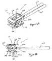
- FIG. 5Ais a perspective view of a distractible intervertebral body fusion device according to an aspect of the present invention.
- FIG. 5Bis a side view of the distractible intervertebral body fusion device of FIG. 5A .
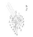
- FIG. 6Ais a perspective view of the distractible intervertebral body fusion device of FIG. 5A in an expanded configuration.
- FIG. 6Bis a side view of the distractible intervertebral body fusion device of FIG. 5A in an expanded configuration.
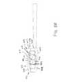
- FIG. 7is a simplified view of the distractible intervertebral body fusion device of FIG. 5A .
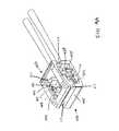
- FIG. 8Ais a perspective view of a distractible intervertebral body fusion device according to an aspect of the present invention.
- FIG. 8Bis a side view of the distractible intervertebral body fusion device of FIG. 8A .
- FIG. 9Ais a perspective view of the distractible intervertebral body fusion device of FIG. 8A in an expanded configuration.
- FIG. 9Bis a side view of the distractible intervertebral body fusion device of FIG. 8A in an expanded configuration.
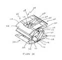
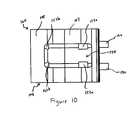
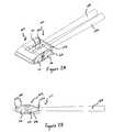
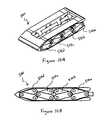
- FIG. 10Ais a perspective view of a distractible intervertebral body fusion device according to an aspect of the present invention.
- FIG. 10Bis a side view of the distractible intervertebral body fusion device of FIG. 10A .
- FIG. 11Ais a perspective view of the distractible intervertebral body fusion device of FIG. 10A in an expanded configuration.
- FIG. 11Bis a side view of the distractible intervertebral body fusion device of FIG. 10A in an expanded configuration.
- FIG. 11Cis a top view of the distractible intervertebral body fusion device of FIG. 10A in an expanded configuration.
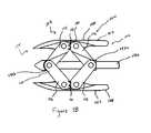
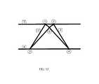
- FIG. 12is a simplified of a distractible intervertebral body fusion device according to an aspect of the present invention.
- FIG. 13is a perspective view of a base plate for a distractible intervertebral body fusion device according to an embodiment of the present invention.
- Device 100includes a device body 102 .
- Device body 102can include a nose portion 104 , a rear portion 106 , a pair of opposed base plates 108 having outer bearing surfaces 107 , and arms 110 .
- bearing surfacerefers to the outside surface of a base plate that interfaces with the endplate of a vertebra.
- Each arm 110can include a pair of structural members 112 hingedly attached to each other, with each structural member 112 hingedly attached to one of the base plates 108 .
- structural members 112are hinged to each other and to base plates 108 with pins 114 .
- Structural members 112 on opposing arms 110can interlock with each other via gear teeth 111 positioned on the ends of structural members 112 .
- Gear teeth 111are arranged so as to keep the device 100 stable when it is distracted within the body and supporting a load.
- device 100includes a pair of arms 110 on a first side 116 and a pair of arms 110 on a second side 118 of device 100 .
- Threaded members 120can be inserted through blocks 122 a attached to the arm 110 nearest the rear portion 106 and into blocks 122 b attached to the arm 110 nearest the nose portion 104 . Actuation of threaded members 120 in a first direction drives blocks 122 closer together, which causes expansion of arms 110 and distraction of base plates 108 . Actuation of threaded members 120 in the opposite direction would drive blocks 122 apart, thereby bringing base plates 108 closer together. This back-drivability of the device 100 is helpful for sizing the device 100 and removing the device 100 if necessary, such as in the event of post-surgical infection or trauma.
- portions of the threaded members 120may be reverse threaded to allow distraction without changing the position of the threaded members along the respective axes of the threaded members helping to keep the device from adversely interacting with the anatomy of the patient.
- blocks 122 acan be tapped to accommodate threaded members 120 and blocks 122 b can provide a clearance fit with threaded members 120 . When threaded members 120 are actuated, this allows blocks 122 b to be pulled towards blocks 122 a , causing the device 100 to distract.
- threaded members 120can extend through apertures directly through structural members 112 .
- each base plate 108includes an opening 124 to facilitate bone growth through the device 100 .
- Openings 124promote vertebral fusion because bone can grow directly through the device 100 .
- opening 124can comprise any shape.
- Endplates 108can also have a rough surface or teeth 109 ( FIG. 13 ) to create friction with the base plates of the vertebra to prevent accidental extrusion of he device 100 or to promote bone growth for successful fusion.
- Nose portion 104can be tapered to facilitate insertion of the device 100 into the disc space.
- Rear portion 106can also be tapered.
- device body 102is shaped to be ergonomic.
- Device body 102can have various shapes, such as, for example, rectangular or kidney-shaped.
- a kidney-shaped device body 102maximizes contact between the device and the vertebral bodies because the base plates of vertebrae tend to be slightly concave.
- One or both ends of the devicemay also be tapered to facilitate insertion. This minimizes the amount of force needed to initially separate the vertebral bodies.
- the devicemay be convex along both its length and its width, or bi-convex.
- Device bodycan also be comprised of various materials. Such materials can include, for example, titanium, steel, PEEK and carbon fiber. Device can also be constructed in various sizes depending on the type of vertebra and size of patient with which it is being used.
- the threaded member 120can be micro-machined, or split along its length and reconnected using a bellows or flexible torque transmission device, to be able to operate through an angle that may be necessitated by the shape of the device.
- Device 100can be placed between adjacent vertebrae or vertebral bodies and used to distract the endplates of the adjacent vertebral bodies and subsequently serve as a fusion device.
- One or more insertion tools 150can be used to insert and distract device 100 .
- the device body 102can be seen in its initial compressed configuration.
- FIGS. 3A and 3Bdevice body 102 is in an expanded configuration.
- Insertion tools 150can be connected to threaded members 120 and first used to insert device 100 into a desired location.
- Device 100can be inserted with tapered nose portion 104 first.
- One device 100can be inserted, or, for additional support, two devices 100 can be inserted.
- Two devices 100each sized to be inserted within one-half of the evacuated disc space, can be especially useful for treating larger patients in which the device may encounter higher loads.
- three or more small devicescan be inserted into the disc space in order to very accurately control the orientation and distance between the discs.
- Three or more distraction mechanismsmay be positioned circumferentially between two circular endplates to result in very accurate control and orientation of the base plates. Such a device would resemble a hexapod.
- insertion tools 150can be used to rotate threaded members 120 in a first direction. This causes blocks 122 b to be pulled towards blocks 122 a , which causes arms 110 to expand and base plates 108 to distract. Threaded members 120 can be actuated the same amount (either simultaneously or independently) for uniform distraction or can be actuated different amounts for non-uniform distraction with one side 116 or 118 of the device higher than the other.
- the endplates 108 or other elements of the device 100may in some embodiments be made compliant for exaggerated non-uniform distraction while maintaining the stability of the device 100 . Once base plates 108 are distracted to a desired degree, insertion tools can be disconnected from threaded members 120 and the device 100 can remain within the body.
- a locking mechanismcan be utilized to prevent rotation of the threaded members to ensure the device remains in the distracted state.
- the locking mechanismcan be activated with the insertion device.
- lockingmay be enhanced by tightening a threaded nut (not shown) against one or more of the threaded blocks 122 .
- Device 100is capable of stably supporting the vertebral bodies in the distracted position.
- Interlocked gear teeth 111 of structural members 112 in addition to threaded members 120 interlocked with blocks 122constrain the device such that there are zero, or fewer, degrees of freedom.
- a typical four bar planar linkagehas four links and has four kinematic pairs each limiting two degrees of freedom and each allowing one degree freedom resulting in the four bar planar linkage having one degree of freedom overall.
- Gears such as those of gear teeth 111may be added as described above to create one additional kinematic pair limiting the device in one or more additional degree(s) of freedom thus resulting in an overall freedom of zero or fewer degrees of freedom. That is, none of the linkages that comprise the device are capable of independent movement with respect to the other linkages.
- a crush surface or compliant materialsmay be used in concert with or in place of the interlocking gear teeth 111 or hinges 114 to minimize hysteresis that may be present in the device 100 and due to clearance in the gear teeth 111 and hinge mechanisms 114 necessary for overcoming the over-constraint in devices having fewer than zero degrees of freedom.
- a bone growth stimulantsuch as autograft, bone morphogenic protein, or bone enhancing material
- a bone growth stimulantcan be delivered into an open area defined within the device.
- bone growth stimulantis delivered after insertion tools 150 are disconnected.
- bone growth stimulantis delivered through an open area between insertion tools 150 .
- bone growth stimulantcan be delivered by the insertion tools 150 through a hollow chamber within insertion tools 150 .
- Deviceis then capable of supporting in-vivo loads during the 6 to 12 weeks that fusion occurs between the vertebral bodies.
- openings 124 in base plates 108promote and allow for bone growth into and through the device 100 .
- FIGS. 4A-4Cthere can be seen another embodiment of a distractible intervertebral fusion device 200 according to an aspect of the present invention.
- This embodiment of the device 200similarly includes a device body 202 having a pair of opposed base plates 208 with outer bearing surfaces 207 connected with arms 210 that are distractible with threaded members 220 .
- threaded members 220are positioned outside of arms 210 , as opposed to device 100 , where the threaded members 120 are positioned inside of the arms 110 .
- Thisprovides for additional space between insertion tools 250 and threaded members 220 for delivering bone growth stimulant to aid in vertebral fusion following distraction. Additionally the external location of the screws may enhance the ability of the device to carry torsional loading the device may experience during implantation or fusion.
- Device 300includes a device body 302 including a nose portion 304 , a rear portion 306 , a pair of opposed base plates 308 with outer bearing surfaces 307 , and arms 310 .
- Each arm 310includes a pair of structural members 312 hingedly attached to each other and to one of the base plates 308 .
- structural members 312are hinged to each other and to base plates 308 with pins 314 .
- Device 300can have arms 310 on both side 316 , 318 of device 300 .
- Device 300can include a third arm 310 c in addition to a first arm 310 a and second arm 310 b .
- third arm 310 cis attached to base plates 308 with the same pins 314 as second arm 310 b .
- third arm 310 cis separately hinged to base plates 308 .
- Third arm 310 ccan be positioned at any point along base plates 108 between nose portion 304 and rear portion 306 .
- Third arm 310 cprovides a means for stably maintaining the device 300 under in-vivo loads when in a distracted position. As is demonstrated by a simplified form of device 300 shown in FIG.
- the rigid link 310 amay be slightly longer than either 310 c or 310 b thus resulting in the rear portion 306 of the device 300 having a distracted height that is slightly greater than the distracted height of the nose portion 304 of the device 300 .
- block 322 amay be supplemented with a differential screw mechanism that would allow the position of block 322 a to be independently controlled with respect to block 322 b .
- Such control of 322 awould allow the lordosis, or angular orientation of the endplates, to be matched exactly to the unique lordosis, or desired lordosis, of a patient's spine.
- the differential screw mechanismwould be accomplished by threading an internally and externally threaded cylinder over the threaded member 320 but within the block 322 a .
- the threaded cylindercould then be removeably coupled to an external drive device as threaded member 320 is removeably coupled to insertion tool 350 .
- the devicewhen portions of the threaded members are not reverse threaded and clearance exists in block 322 c the device may be able to be gently and additionally distracted due to in-vivo axial tension as the clearance in block 322 c allows block 322 c to slide closer to block 322 b and block 322 a .
- having distracted slightly under tensile loadingthe device would return to the original height as compressive loading is returned.
- the parallelismwould remain unchanged, while lordotic endplates may undergo a small angular displacement that would return to the set lordosis with the reapplication of the normal compressive loading.
- This extensibility of the devicecould offer great benefits to the fusion process as the endplates, which may be growing into the endplates of the vertebral bodies, would not be pulled away, damaging early bone growth, from the endplates by motion of the patient's spine.
- threaded members 320such as screws, and insertion tool 350 can be used to distract device from the compressed state shown in FIGS. 5A and 5B to a distracted state, such as the one shown in FIGS. 6A and 6B .
- device 300has three arms 310 , threaded members 320 are inserted through first blocks 322 a attached to the first arms 310 a , through second blocks 322 b attached to the second arms 310 b , and into third blocks 322 c attached to the third arms 310 c . Actuation of threaded members 320 in a first direction drives blocks 322 closer together, which causes expansion of arms 310 and distraction of base plates 308 .
- Actuation of threaded members 320 in the opposite directionwould drive blocks 322 apart, thereby bringing base plates 308 closer together.
- blocks 322 a and 322 bcan be tapped to accommodate threaded members 320 and blocks 322 c can provide a clearance fit with threaded members 320 .
- threaded members 120When threaded members 120 are actuated, this allows blocks 322 c to be pulled towards blocks 322 a , 322 b , causing the device 300 to distract.
- a distractible intervertebral body fusion device 500can include a fourth arm 510 d in addition to first 510 a , second 510 b , and third 510 c arms.
- Device 500can also include a corresponding fourth block 522 d connected to fourth arm 510 d in addition to first 522 a , second 522 b , and third 522 c arms through which threaded members 520 extend.
- the device 500is also capable of stably supporting the disc space. In fact, the device 500 is actually over-constrained in that it has additional constraints (i.e., a fourth arm 510 d ) over and above what is necessary to constrain the device 500 to have zero degrees of freedom.
- Device 400includes a device body 402 including a nose portion 404 , a rear portion 406 , a pair of opposed base plates 408 having outer bearing surfaces 407 , and arms 410 .
- Device 400can have arms 410 on both side 416 , 418 of device 400 .
- Arms 410 of device 400are hingedly attached to each other with a pin 414 .
- arms 410comprise a single structural member 412 and form a generally x-shape with each other.
- Each arm 410has one end hingedly attached to one of the base plates 408 and the other end slidably attached to a slot 409 in the opposite base plate 408 .
- the device 400is distracted from the compressed configuration shown in FIGS. 8A and 8B to an expanded configuration such as the one shown in FIGS. 9A and 9B by rotating a threaded member 420 within blocks 422 attached to arms 410 .
- the pins 414 slidably disposed within slots 409translate within slots 409 from an end nearest the nose portion 404 towards an end nearest the rear portion 406 to allow arms 410 to expand, which causes base plates 408 to distract.
- This devicealso stably supports the disc space.
- the devicehas four rigid links, two one-degree of freedom kinematic pairs (pinned joints), and two two-degree of freedom kinematic pairs (slidably disposed joints) that may be locked in place within the slots 409 making them one degree of freedom kinematic pairs.
- the device 400could be constructed such that both ends of each arm 410 and the pins 414 to which the arms 410 are affixed are slidably disposed within a broader slot 409 and the arm assembly remains centered along the length of the device by translationally fixing the threaded member 420 along its length while allowing it to rotate.
- portions of the threaded member 420could be reverse threaded such that turning the threaded member 420 would move threaded block 422 and its reverse threaded complement towards each other.
- 1Acould be created such that the slidably disposed mechanism of embodiment 400 could be implemented as the drive mechanism on the bottom plate 408 and the pinned hinges 114 with gear teeth 111 can be used as the means of stabilizing the top plate 108 .
- the linksmay not be crossed as in the embodiment 400 . Instead, the links could be configured similarly to a horizontally mirrored pair of links 112 of embodiment 100 .
- devicescan also include pins 415 extending vertically through devices and slidably disposed within or relative to one of the endplates, either top or bottom, of the device.
- Pins 415add torsional stiffness to the device to help keep the end plates parallel during distraction.
- Pinscan be of any shape, such as for, example, rectangular, circular, elliptical, oblong, or hexagonal.
- In-vivo torsionmay be one of the major challenges prohibiting the successful approval and market release of low-profile distractable fusion-devices. In-vivo dynamic torsional loading may exceed 10 [Nm] and static torsional loading may exceed 10-20 [Nm].
- the pinsalso help to support the in-vivo dynamic shear load which can be greater than 600 to 750 [N] with an additional and often equal, in magnitude, compressive component. Although depicted as having four pins at the corners of the device, it should be understood that different numbers of pins in various locations can be utilized.
- mechanisms other than threaded memberscan be used to distract the device.
- Such mechanismsinclude, for example, a pop-rivet mechanism, a sardine key and ribbon, a tourniquet and wire, a saw blade/ratchet, a zip-tie-like mechanism, piezo-electric inch worm motors and shape changing materials such as a shape member alloy or a conducting polymer actuator.
- a lumbar implantcan be 6 mm in height, expandable to 12 mm in height, with a length of 25-30 mm and a width of 6 mm.
- the implantcan be inserted through a minimally invasive tubular port that goes through the muscle of the lumbar spine and into the lumbar disc space. Prior to inserting the implant, the lumbar disc should be completely removed.
- a cervical implantcan be 6 mm in height, expandable to 10 mm in height, with a length of 10 mm and a width of 6 mm.
- the implantcan be inserted after anterior cervical surgical exposure.
- the cervical discshould be completely removed prior to insertion of the implant.
Landscapes
- Health & Medical Sciences (AREA)
- Engineering & Computer Science (AREA)
- Biomedical Technology (AREA)
- Orthopedic Medicine & Surgery (AREA)
- Neurology (AREA)
- Transplantation (AREA)
- Heart & Thoracic Surgery (AREA)
- Oral & Maxillofacial Surgery (AREA)
- Cardiology (AREA)
- Vascular Medicine (AREA)
- Life Sciences & Earth Sciences (AREA)
- Animal Behavior & Ethology (AREA)
- General Health & Medical Sciences (AREA)
- Public Health (AREA)
- Veterinary Medicine (AREA)
- Physical Education & Sports Medicine (AREA)
- Prostheses (AREA)
Abstract
Description
Claims (13)
Priority Applications (2)
| Application Number | Priority Date | Filing Date | Title |
|---|---|---|---|
| US12/407,608US8628577B1 (en) | 2009-03-19 | 2009-03-19 | Stable device for intervertebral distraction and fusion |
| US14/153,281US9867717B2 (en) | 2009-03-19 | 2014-01-13 | Stable device for intervertebral distraction and fusion |
Applications Claiming Priority (1)
| Application Number | Priority Date | Filing Date | Title |
|---|---|---|---|
| US12/407,608US8628577B1 (en) | 2009-03-19 | 2009-03-19 | Stable device for intervertebral distraction and fusion |
Related Child Applications (1)
| Application Number | Title | Priority Date | Filing Date |
|---|---|---|---|
| US14/153,281ContinuationUS9867717B2 (en) | 2009-03-19 | 2014-01-13 | Stable device for intervertebral distraction and fusion |
Publications (1)
| Publication Number | Publication Date |
|---|---|
| US8628577B1true US8628577B1 (en) | 2014-01-14 |
Family
ID=49886039
Family Applications (2)
| Application Number | Title | Priority Date | Filing Date |
|---|---|---|---|
| US12/407,608Active2030-06-02US8628577B1 (en) | 2009-03-19 | 2009-03-19 | Stable device for intervertebral distraction and fusion |
| US14/153,281Active2030-12-10US9867717B2 (en) | 2009-03-19 | 2014-01-13 | Stable device for intervertebral distraction and fusion |
Family Applications After (1)
| Application Number | Title | Priority Date | Filing Date |
|---|---|---|---|
| US14/153,281Active2030-12-10US9867717B2 (en) | 2009-03-19 | 2014-01-13 | Stable device for intervertebral distraction and fusion |
Country Status (1)
| Country | Link |
|---|---|
| US (2) | US8628577B1 (en) |
Cited By (98)
| Publication number | Priority date | Publication date | Assignee | Title |
|---|---|---|---|---|
| US20110319898A1 (en)* | 2010-06-24 | 2011-12-29 | O'neil Michael J | Instruments and Methods for Non-Parallel Disc Space Preparation |
| US20130304214A1 (en)* | 2011-07-14 | 2013-11-14 | Nlt Spine Ltd. | Laterally Deflectable Implant |
| US20140180419A1 (en)* | 2012-12-14 | 2014-06-26 | Facet-Link Inc. | Continuously height-adjustable intervertebral fusion implant |
| US20140277492A1 (en)* | 2013-03-18 | 2014-09-18 | Chih-Hsuan Wei | Expandable Implant of a Minimally Invasive Surgery |
| US20150018951A1 (en)* | 2013-07-09 | 2015-01-15 | Nlt Spine Ltd. | Orthopedic Implant with Adjustable Angle between Tissue Contact Surfaces |
| US8940049B1 (en)* | 2014-04-01 | 2015-01-27 | Ex Technology, Llc | Expandable intervertebral cage |
| US9226764B2 (en) | 2012-03-06 | 2016-01-05 | DePuy Synthes Products, Inc. | Conformable soft tissue removal instruments |
| EP2992859A1 (en)* | 2014-09-02 | 2016-03-09 | FACET-LINK Inc. | Continuously adjustable intervertebral implant |
| US9381092B2 (en) | 2008-12-31 | 2016-07-05 | Ex Technology, Llc | Flexible joint arrangement incorporating flexure members |
| WO2016108994A1 (en)* | 2014-04-01 | 2016-07-07 | Ex Technology, Llc | Expandable intervertebral cage |
| US9408712B2 (en) | 2010-07-15 | 2016-08-09 | NLT-Spine Ltd. | Surgical systems and methods for implanting deflectable implants |
| US9414936B2 (en) | 2011-12-19 | 2016-08-16 | Warsaw Orthopedic, Inc. | Expandable interbody implant and methods of use |
| US9445919B2 (en) | 2011-12-19 | 2016-09-20 | Warsaw Orthopedic, Inc. | Expandable interbody implant and methods of use |
| US9474626B2 (en) | 2009-07-22 | 2016-10-25 | Spinex Tec Llc | Methods and apparatuses for vertebral body distraction and fusion employing a coaxial screw gear sleeve mechanism |
| US9498270B2 (en) | 2011-07-22 | 2016-11-22 | SpineX Tee, LLC | Methods and apparatus for insertion of vertebral body distraction and fusion devices |
| US20170042695A1 (en)* | 2015-08-12 | 2017-02-16 | Warsaw Orthopedic, Inc. | Expandable spinal implant and method of implanting same |
| US20170112630A1 (en)* | 2015-10-26 | 2017-04-27 | Warsaw Orthopedic, Inc. | Spinal implant system and method |
| US9730806B2 (en) | 2014-10-27 | 2017-08-15 | Warsaw Orthopedic, Inc. | Spinal implant system and method |
| US20170231778A1 (en)* | 2014-08-18 | 2017-08-17 | 41Medical Ag | Intervertebral implant |
| US9737411B2 (en) | 2013-12-11 | 2017-08-22 | Nlt Spine Ltd. | Worm-gear actuated orthopedic implants and methods |
| US9750618B1 (en) | 2016-11-29 | 2017-09-05 | Amendia, Inc. | Intervertebral implant device with independent distal-proximal expansion |
| CN107157629A (en)* | 2017-06-15 | 2017-09-15 | 北京安德思考普商贸有限公司 | New vertebrae mixer |
| US20170325972A1 (en)* | 2016-05-11 | 2017-11-16 | Zimmer, Inc. | Femoral head press instrument for prosthetic implant |
| US9820865B2 (en) | 2013-10-31 | 2017-11-21 | Nlt Spine Ltd. | Adjustable implant |
| US20170333203A1 (en)* | 2009-10-15 | 2017-11-23 | Globus Medical, Inc. | Expandable fusion device and method of installation thereof |
| US9827031B2 (en)* | 2010-05-28 | 2017-11-28 | Benvenue Medical, Inc. | Disc space sizing devices |
| US9867717B2 (en) | 2009-03-19 | 2018-01-16 | Ex Technology, Llc | Stable device for intervertebral distraction and fusion |
| US9907670B2 (en) | 2015-01-21 | 2018-03-06 | Warsaw Orthopedic, Inc. | Unitarily formed expandable spinal implant and method of manufacturing and implanting same |
| US9931224B2 (en) | 2009-11-05 | 2018-04-03 | DePuy Synthes Products, Inc. | Self-pivoting spinal implant and associated instrumentation |
| US9937053B2 (en) | 2014-11-04 | 2018-04-10 | Warsaw Orthopedic, Inc. | Expandable interbody implant |
| US9937054B2 (en) | 2016-01-28 | 2018-04-10 | Warsaw Orthopedic, Inc. | Expandable implant and insertion tool |
| US10016284B2 (en) | 2005-04-12 | 2018-07-10 | Moskowitz Family Llc | Zero-profile expandable intervertebral spacer devices for distraction and spinal fusion and a universal tool for their placement and expansion |
| US10022245B2 (en) | 2012-12-17 | 2018-07-17 | DePuy Synthes Products, Inc. | Polyaxial articulating instrument |
| US10076423B2 (en) | 2016-01-04 | 2018-09-18 | Warsaw Orthopedic, Inc. | Pivoting wedge expanding spinal implant and method of implanting same |
| US10098751B2 (en) | 2004-06-09 | 2018-10-16 | Vexim | Methods and apparatuses for bone restoration |
| US10137006B2 (en) | 2016-01-28 | 2018-11-27 | Warsaw Orthopedic, Inc. | Geared cam expandable interbody implant and method of implanting same |
| US10188526B2 (en) | 2015-10-26 | 2019-01-29 | Warsaw Orthopedic, Inc. | Spinal implant system and method |
| CN109602466A (en)* | 2018-12-17 | 2019-04-12 | 南昌市第医院 | A kind of cervical facet joint fusion device |
| US10336028B1 (en)* | 2015-07-28 | 2019-07-02 | University Of South Florida | Waterproof shape-shifting surface |
| CN110025412A (en)* | 2019-05-21 | 2019-07-19 | 谢林 | The minimally invasive expanding Invasive lumbar fusion device of novel cervical vertebra under a kind of Percutaneous endoscopic |
| US10492923B2 (en) | 2014-06-25 | 2019-12-03 | Seaspine, Inc. | Expanding implant with hinged arms |
| US10603080B2 (en) | 2013-12-23 | 2020-03-31 | Vexim | Expansible intravertebral implant system with posterior pedicle fixation |
| US10610376B2 (en) | 2015-10-16 | 2020-04-07 | Warsaw Orthopedic, Inc. | Expandable spinal implant system and method |
| CN111096825A (en)* | 2018-10-26 | 2020-05-05 | 殷国勇 | Intravertebral bone support assembly |
| CN111528946A (en)* | 2020-05-07 | 2020-08-14 | 吕奕萱 | Knee joint spreader |
| US10966843B2 (en) | 2017-07-18 | 2021-04-06 | DePuy Synthes Products, Inc. | Implant inserters and related methods |
| US10973650B2 (en) | 2015-12-30 | 2021-04-13 | Nuvasive, Inc. | Lordotic expandable fusion implant |
| US11026805B2 (en)* | 2019-07-30 | 2021-06-08 | Loubert S. Suddaby | Expandable intervertebral fusion implant |
| US11045331B2 (en) | 2017-08-14 | 2021-06-29 | DePuy Synthes Products, Inc. | Intervertebral implant inserters and related methods |
| US11116644B2 (en) | 2018-05-25 | 2021-09-14 | Mirus Llc | Multiple expansion stage interbody devices |
| US20220008222A1 (en)* | 2009-10-15 | 2022-01-13 | Globus Medical, Inc. | Expandable fusion device and method of installation thereof |
| US11224453B2 (en) | 2014-07-08 | 2022-01-18 | Spinal Elements, Inc. | Apparatus and methods for disrupting intervertebral disc tissue |
| US11234835B2 (en) | 2019-03-05 | 2022-02-01 | Octagon Spine Llc | Transversely expandable minimally invasive intervertebral cage |
| US11234833B2 (en) | 2015-05-12 | 2022-02-01 | Nuvasive, Inc. | Expandable lordosis intervertebral implants |
| US11253170B2 (en)* | 2016-02-01 | 2022-02-22 | Zimmer Biomet Spine, Inc. | Expandable paddle distractor |
| US11266513B2 (en) | 2018-12-21 | 2022-03-08 | Stryker European Operations Limited | Device for measuring intervertebral space |
| US11273047B2 (en) | 2017-12-18 | 2022-03-15 | Nuvasive, Inc. | Expandable implant device |
| US11278423B2 (en) | 2017-09-29 | 2022-03-22 | Mirus Llc | Expandable interbody devices |
| US11311388B2 (en)* | 2020-08-20 | 2022-04-26 | Spinal Simplicity, Llc | Interspinous process implant |
| US11344424B2 (en) | 2017-06-14 | 2022-05-31 | Medos International Sarl | Expandable intervertebral implant and related methods |
| US11344430B2 (en)* | 2009-10-15 | 2022-05-31 | Globus Medical, Inc. | Expandable fusion device and method of installation thereof |
| US11369490B2 (en) | 2011-03-22 | 2022-06-28 | DePuy Synthes Products, Inc. | Universal trial for lateral cages |
| US20220265436A1 (en)* | 2021-02-19 | 2022-08-25 | Loubert S. Suddaby | Expandable intervertebral fusion implant |
| US11426290B2 (en) | 2015-03-06 | 2022-08-30 | DePuy Synthes Products, Inc. | Expandable intervertebral implant, system, kit and method |
| US11432942B2 (en) | 2006-12-07 | 2022-09-06 | DePuy Synthes Products, Inc. | Intervertebral implant |
| US11446156B2 (en) | 2018-10-25 | 2022-09-20 | Medos International Sarl | Expandable intervertebral implant, inserter instrument, and related methods |
| US11446155B2 (en) | 2017-05-08 | 2022-09-20 | Medos International Sarl | Expandable cage |
| US11452607B2 (en) | 2010-10-11 | 2022-09-27 | DePuy Synthes Products, Inc. | Expandable interspinous process spacer implant |
| US11471145B2 (en) | 2018-03-16 | 2022-10-18 | Spinal Elements, Inc. | Articulated instrumentation and methods of using the same |
| US11497622B2 (en) | 2019-03-05 | 2022-11-15 | Ex Technology, Llc | Transversely expandable minimally invasive intervertebral cage and insertion and extraction device |
| US11497619B2 (en) | 2013-03-07 | 2022-11-15 | DePuy Synthes Products, Inc. | Intervertebral implant |
| US11510788B2 (en) | 2016-06-28 | 2022-11-29 | Eit Emerging Implant Technologies Gmbh | Expandable, angularly adjustable intervertebral cages |
| US11564811B2 (en) | 2015-02-06 | 2023-01-31 | Spinal Elements, Inc. | Graft material injector system and method |
| US11583327B2 (en) | 2018-01-29 | 2023-02-21 | Spinal Elements, Inc. | Minimally invasive interbody fusion |
| US11596522B2 (en) | 2016-06-28 | 2023-03-07 | Eit Emerging Implant Technologies Gmbh | Expandable and angularly adjustable intervertebral cages with articulating joint |
| US11602438B2 (en) | 2008-04-05 | 2023-03-14 | DePuy Synthes Products, Inc. | Expandable intervertebral implant |
| US11607321B2 (en) | 2009-12-10 | 2023-03-21 | DePuy Synthes Products, Inc. | Bellows-like expandable interbody fusion cage |
| US11612491B2 (en) | 2009-03-30 | 2023-03-28 | DePuy Synthes Products, Inc. | Zero profile spinal fusion cage |
| US11622868B2 (en) | 2007-06-26 | 2023-04-11 | DePuy Synthes Products, Inc. | Highly lordosed fusion cage |
| US11654033B2 (en) | 2010-06-29 | 2023-05-23 | DePuy Synthes Products, Inc. | Distractible intervertebral implant |
| US20230181329A1 (en)* | 2020-06-25 | 2023-06-15 | Life Spine, Inc. | Expandable implant assembly |
| US11679000B2 (en) | 2013-05-22 | 2023-06-20 | Nuvasive, Inc. | Expandable fusion implant and related methods |
| US11737881B2 (en) | 2008-01-17 | 2023-08-29 | DePuy Synthes Products, Inc. | Expandable intervertebral implant and associated method of manufacturing the same |
| US11744715B2 (en) | 2016-11-01 | 2023-09-05 | Warsaw Orthopedic, Inc. | Expandable spinal implant system with a biased tip and method of using same |
| US11752009B2 (en) | 2021-04-06 | 2023-09-12 | Medos International Sarl | Expandable intervertebral fusion cage |
| US11771483B2 (en) | 2017-03-22 | 2023-10-03 | Spinal Elements, Inc. | Minimal impact access system to disc space |
| US11806245B2 (en) | 2020-03-06 | 2023-11-07 | Eit Emerging Implant Technologies Gmbh | Expandable intervertebral implant |
| US11850160B2 (en) | 2021-03-26 | 2023-12-26 | Medos International Sarl | Expandable lordotic intervertebral fusion cage |
| US11872139B2 (en) | 2010-06-24 | 2024-01-16 | DePuy Synthes Products, Inc. | Enhanced cage insertion assembly |
| USRE49973E1 (en) | 2013-02-28 | 2024-05-21 | DePuy Synthes Products, Inc. | Expandable intervertebral implant, system, kit and method |
| USRE49994E1 (en) | 2013-03-14 | 2024-06-04 | Spinal Elements, Inc. | Spinal fusion implants and devices and methods for deploying such implants |
| US12011365B2 (en) | 2022-07-18 | 2024-06-18 | Octagon Spine Llc | Transversely expandable minimally invasive inter vertebral cage |
| US12090064B2 (en) | 2022-03-01 | 2024-09-17 | Medos International Sarl | Stabilization members for expandable intervertebral implants, and related systems and methods |
| US12097126B2 (en) | 2021-09-29 | 2024-09-24 | Ex Technology, Llc | Expandable intervertebral cage |
| US12133664B2 (en) | 2022-12-13 | 2024-11-05 | Spinal Simplicity, Llc | Medical implant |
| CN119523696A (en)* | 2023-08-29 | 2025-02-28 | 武汉联影智融医疗科技有限公司 | Interbody fusion device |
| US12318307B2 (en) | 2021-07-16 | 2025-06-03 | Blue Ocean Spine Gmbh | Adjustable spinal implants, associated instruments and methods |
| US12440346B2 (en) | 2023-03-31 | 2025-10-14 | DePuy Synthes Products, Inc. | Expandable intervertebral implant |
Families Citing this family (19)
| Publication number | Priority date | Publication date | Assignee | Title |
|---|---|---|---|---|
| WO2008124831A2 (en)* | 2007-04-10 | 2008-10-16 | Lee David M D | Adjustable spine distraction implant |
| US9301788B2 (en) | 2008-04-10 | 2016-04-05 | Life Spine, Inc. | Adjustable spine distraction implant |
| EP2547292B1 (en) | 2010-03-16 | 2019-04-24 | Pinnacle Spine Group, LLC | Ntervertebral implants and graft delivery systems |
| US12370057B2 (en)* | 2010-09-03 | 2025-07-29 | Globus Medical, Inc. | Expandable fusion device and method of installation thereof |
| US9308099B2 (en) | 2011-02-14 | 2016-04-12 | Imds Llc | Expandable intervertebral implants and instruments |
| US9380932B1 (en) | 2011-11-02 | 2016-07-05 | Pinnacle Spine Group, Llc | Retractor devices for minimally invasive access to the spine |
| WO2014159739A1 (en) | 2013-03-14 | 2014-10-02 | Pinnacle Spine Group, Llc | Interbody implants and graft delivery systems |
| US10500061B2 (en)* | 2015-08-13 | 2019-12-10 | K2M, Inc. | Adjustable spinal implant |
| JP6949006B2 (en) | 2015-08-25 | 2021-10-13 | アイエムディーエス リミテッド ライアビリティ カンパニー | Expandable facet implant |
| US10137007B2 (en) | 2016-05-05 | 2018-11-27 | Warsaw Orthopedic, Inc. | Geared cam expandable interbody implant and method of implanting same |
| WO2018081322A1 (en) | 2016-10-25 | 2018-05-03 | Imds Llc | Methods and instrumentation for intervertebral cage expansion |
| USD946151S1 (en)* | 2020-11-06 | 2022-03-15 | Mirus Llc | Medical device |
| USD946152S1 (en)* | 2020-11-06 | 2022-03-15 | Mirus Llc | Medical device |
| US10945859B2 (en) | 2018-01-29 | 2021-03-16 | Amplify Surgical, Inc. | Expanding fusion cages |
| WO2019161393A1 (en)* | 2018-02-16 | 2019-08-22 | Mcmains Michael Craig | Expandable interbody device |
| CN109199560B (en)* | 2018-11-13 | 2023-12-05 | 廖若辰 | Support capable of being spread and supporting bone grafting |
| WO2021163708A1 (en)* | 2020-02-13 | 2021-08-19 | Nexus Spine, LLC | Deployable ramped nose for implantable medical devices |
| US11547573B2 (en)* | 2020-04-08 | 2023-01-10 | K2M, Inc. | Expandable interbody implant with teeth driven linkages |
| CN112998915A (en)* | 2021-01-29 | 2021-06-22 | 苏州大学 | Bone loosening type locking spinal fusion cage |
Citations (103)
| Publication number | Priority date | Publication date | Assignee | Title |
|---|---|---|---|---|
| US2106088A (en) | 1936-05-08 | 1938-01-18 | Gen Electric | Drive mechanism |
| US2231221A (en) | 1937-06-01 | 1941-02-11 | Laurence L Rector | Packing device |
| US2453656A (en) | 1945-09-15 | 1948-11-09 | Bullard Co | Rack and pinion gear means |
| US2666334A (en) | 1947-07-17 | 1954-01-19 | Charles R Nalle | Threaded article and support therefor |
| US2711105A (en) | 1951-06-02 | 1955-06-21 | Williams Earl Charles | Power transmission |
| US2842976A (en) | 1955-11-21 | 1958-07-15 | Young Sidney Geoffrey | Gear mechanisms |
| US3386128A (en) | 1966-09-26 | 1968-06-04 | Ryan Aeronautical Co | Self-actuating, self-locking hinge |
| US3449971A (en) | 1967-06-12 | 1969-06-17 | Lear Siegler Inc | Linear actuator |
| US3596863A (en) | 1969-01-28 | 1971-08-03 | Nasa | Fine adjustment mount |
| US3708925A (en) | 1969-09-30 | 1973-01-09 | Tsukihoshi Gomu Kk | Screw-shaped gear hone and method of forming and using the same |
| US3709132A (en) | 1970-11-27 | 1973-01-09 | Polaroid Corp | Photographic focus adjustment apparatus |
| US3916596A (en) | 1973-02-28 | 1975-11-04 | Hanley Ronald | Joint structure |
| US4261211A (en) | 1976-11-24 | 1981-04-14 | Anschutz & Co. G.M.B.H. | Flexure joint, particularly for connecting a gyroscope to its driving shaft |
| US4478109A (en) | 1981-09-28 | 1984-10-23 | Jacob Kobelt | Twin lever control assembly |
| US4528864A (en) | 1980-05-19 | 1985-07-16 | Incosym, Inc. | Universal joint flexure hinge suspension system and method for manufacturing this system |
| US4559717A (en) | 1984-02-21 | 1985-12-24 | The United States Of America As Represented By The Secretary Of Commerce | Flexure hinge |
| US4630495A (en) | 1982-02-11 | 1986-12-23 | Fairey Hydraulics Limited | Variable ratio power transmission means |
| US4691586A (en) | 1985-03-05 | 1987-09-08 | Staat Der Nederlanden (Staatsbedrijf Der Posterijen, Telegrafie En Telfonie) | Fine-adjusting device for accurate positioning an adjusting element |
| US4694703A (en) | 1984-06-28 | 1987-09-22 | Lear Siegler, Inc. | Circumferentially oriented flexure suspension |
| US4869552A (en) | 1988-09-14 | 1989-09-26 | Shelby Williams Industries, Inc. | Flexible backrest assembly for a chair |
| US5133108A (en) | 1990-06-26 | 1992-07-28 | Ftfm La Toulousaine | Panel articulation system |
| US5181371A (en) | 1991-08-05 | 1993-01-26 | Crane Plastics Company | Flexible joint assembly for partition assemblage |
| US5196857A (en) | 1991-06-03 | 1993-03-23 | General Electric Company | Stowable and deployable antenna array |
| US5198932A (en) | 1990-11-14 | 1993-03-30 | Fuji Photo Film Co., Ltd. | Zoom lens assembly |
| JPH0581194A (en) | 1991-09-19 | 1993-04-02 | Nec Software Kansai Ltd | On line data processing method |
| US5222986A (en)* | 1992-01-27 | 1993-06-29 | Wright Donald M | Hand prosthesis for grasping large and small objects |
| US5374556A (en) | 1992-07-23 | 1994-12-20 | Cell Robotics, Inc. | Flexure structure for stage positioning |
| US5439377A (en) | 1994-04-21 | 1995-08-08 | Milanovich; Philip J. | Bi-directional orthodontic appliance |
| US5664457A (en) | 1992-06-05 | 1997-09-09 | Amir Nejati | Screw gear means and method for same |
| US5904479A (en) | 1992-11-12 | 1999-05-18 | Staples; Jeffrey J. | Orthodontic palate expander apparatus |
| US5960670A (en) | 1995-12-12 | 1999-10-05 | Ut Automotive Dearborn, Inc. | Actuator for gear transfer case with cushion at end of travel |
| US5980252A (en) | 1995-05-08 | 1999-11-09 | Samchukov; Mikhail L. | Device and method for enhancing the shape, mass, and strength of alveolar and intramembranous bone |
| US5988006A (en) | 1994-12-12 | 1999-11-23 | Fleytman; Yakov | Method of moving objects with self-locking mechanical transmission |
| US6045579A (en)* | 1997-05-01 | 2000-04-04 | Spinal Concepts, Inc. | Adjustable height fusion device |
| US6056491A (en) | 1999-04-23 | 2000-05-02 | Hsu; Kuo-Tai | Screw having cutting teeth formed on threads thereof |
| US6350317B1 (en) | 1999-12-30 | 2002-02-26 | Lam Research Corporation | Linear drive system for use in a plasma processing system |
| US6378172B1 (en) | 2000-08-01 | 2002-04-30 | Fabri-Craft, Inc. | Airplane container door hinge |
| US6454806B1 (en) | 1999-07-26 | 2002-09-24 | Advanced Prosthetic Technologies, Inc. | Spinal surgical prosthesis |
| US6484608B1 (en) | 2000-06-20 | 2002-11-26 | Hughes Electronics Corporation | Method and apparatus for providing two axis motion with a single drive device |
| US6517772B1 (en) | 2001-09-26 | 2003-02-11 | Federal-Mogul World Wide, Inc. | Apparatus and method for forming powder metal gears |
| US20030077110A1 (en) | 2001-10-22 | 2003-04-24 | Knowles Steven M. | Flexible joint assembly, service, and system using a flexible joint assembly |
| EP1342456A1 (en) | 1996-11-22 | 2003-09-10 | Glenn R. Buttermann | Intervertebral prosthetic device |
| US6641614B1 (en)* | 1997-05-01 | 2003-11-04 | Spinal Concepts, Inc. | Multi-variable-height fusion device |
| US20030233145A1 (en) | 2002-03-11 | 2003-12-18 | Landry Michael E. | Instrumentation and procedure for implanting spinal implant devices |
| WO2004026188A2 (en) | 2002-09-23 | 2004-04-01 | Sdgi Holdings, Inc. | Expandable spinal fusion device and methods of promoting spinal fusion |
| US6719796B2 (en) | 1999-07-26 | 2004-04-13 | Advanced Prosthetic Technologies, Inc. | Spinal surgical prosthesis |
| US6772479B2 (en) | 2001-06-21 | 2004-08-10 | The Aerospace Corporation | Conductive shape memory metal deployment latch hinge |
| US6802229B1 (en) | 2003-06-02 | 2004-10-12 | Michael Lambert | Gear drive having continuously variable drive ratio |
| US6808537B2 (en) | 2000-07-07 | 2004-10-26 | Gary Karlin Michelson | Expandable implant with interlocking walls |
| JP2004301135A (en) | 2003-03-28 | 2004-10-28 | Ntn Corp | Linear driving device |
| US20040225364A1 (en) | 2003-05-06 | 2004-11-11 | Marc Richelsoph | Artificial intervertebral disc |
| US20050000228A1 (en) | 2003-05-20 | 2005-01-06 | Snecma Moteurs | Combustion chamber having a flexible connexion between a chamber end wall and a chamber side wall |
| US20050033431A1 (en) | 2003-08-05 | 2005-02-10 | Charles Gordon | Artificial functional spinal unit assemblies |
| US6863673B2 (en) | 2001-10-17 | 2005-03-08 | Movdice Holding, Inc. | Methods for adjustable bone fusion implants |
| US20050095384A1 (en) | 2003-11-04 | 2005-05-05 | Wittmeyer Larry E.Jr. | Multi-functional stack of repositionable sheets |
| US20050113924A1 (en) | 2003-08-07 | 2005-05-26 | Dynamic Spine, Inc. | Apparatus and method for performing spinal surgery |
| EP1552797A2 (en) | 1999-01-27 | 2005-07-13 | Disc-O-Tech Medical Technologies, Ltd. | Expandable intervertebral spacer |
| US20050175406A1 (en) | 2002-01-22 | 2005-08-11 | Airbus Deutschland Gmbh | Joint for connecting a longitudinal side to an upper side of components and flexible strip for use in such a joint |
| WO2005081330A2 (en) | 2004-02-20 | 2005-09-01 | Thorlabs, Inc. | Positioner device |
| US6953477B2 (en) | 2002-11-01 | 2005-10-11 | Sdgi Holdings, Inc. | Laterally expandable cage |
| WO2005096975A2 (en) | 2004-04-05 | 2005-10-20 | Expanding Orthopedics Inc. | Expandable bone device |
| US20060004447A1 (en) | 2004-06-30 | 2006-01-05 | Depuy Spine, Inc. | Adjustable posterior spinal column positioner |
| US20060004455A1 (en) | 2004-06-09 | 2006-01-05 | Alain Leonard | Methods and apparatuses for bone restoration |
| US20060025862A1 (en) | 2004-07-30 | 2006-02-02 | Spinalmotion, Inc. | Intervertebral prosthetic disc with metallic core |
| US7051610B2 (en) | 2001-11-13 | 2006-05-30 | Douglas Holtz | Ball-worm transmission |
| US20060129244A1 (en) | 2004-10-25 | 2006-06-15 | Alphaspine, Inc. | Expandable intervertebral spacer method and apparatus |
| US7070598B2 (en)* | 2002-06-25 | 2006-07-04 | Sdgi Holdings, Inc. | Minimally invasive expanding spacer and method |
| WO2006094535A1 (en) | 2005-03-09 | 2006-09-14 | Ares Engineering S.R.L. | Rolling screw |
| WO2007009107A2 (en) | 2005-07-14 | 2007-01-18 | Stout Medical Group, P.L. | Expandable support device and method of use |
| US20070032791A1 (en) | 2005-07-14 | 2007-02-08 | Greenhalgh E S | Expandable support device and method of use |
| US20070049943A1 (en) | 2005-04-12 | 2007-03-01 | Nathan Moskowitz | Bi-directional fixating transvertebral body screws, zero-profile horizontal intervertebral miniplates, total intervertebral body fusion devices, and posterior motion-calibrating interarticulating joint stapling device for spinal fusion |
| US7201751B2 (en) | 1997-01-02 | 2007-04-10 | St. Francis Medical Technologies, Inc. | Supplemental spine fixation device |
| US20070129730A1 (en) | 2005-09-12 | 2007-06-07 | Woods Richard W | Posterior modular disc replacement system |
| WO2007076377A2 (en) | 2005-12-19 | 2007-07-05 | Stout Medical Group, L.P. | Expandable support device |
| US20070185577A1 (en) | 2003-09-30 | 2007-08-09 | Malek Michel H | Intervertebral disc prosthesis |
| US20070191954A1 (en)* | 2005-04-21 | 2007-08-16 | Noah Hansell | Expandable Vertebral Prosthesis |
| US20070191958A1 (en) | 2006-02-15 | 2007-08-16 | Abdou M S | Devices and Methods for Inter-Vertebral Orthopedic Device Placement |
| US7273373B2 (en) | 2002-10-31 | 2007-09-25 | K. K. Hollyx | Artificial root of a tooth |
| US20070222100A1 (en) | 2006-03-21 | 2007-09-27 | Huber Engineered Woods L.L.C. | Method and system using NIR spectroscopy for in-line monitoring and controlling content in continuous production of engineered wood products |
| WO2007111979A2 (en)* | 2006-03-24 | 2007-10-04 | Ebi, Llc. | Expandable spinal prosthesis |
| US20070282449A1 (en) | 2006-04-12 | 2007-12-06 | Spinalmotion, Inc. | Posterior spinal device and method |
| US7308747B2 (en) | 2003-01-21 | 2007-12-18 | Insitutec, Inc. | Method of positioning a platform relative to a fixed frame and a small scale positioning device |
| US20070293329A1 (en) | 2006-06-08 | 2007-12-20 | Emuge-Werk Richard Glimpel Gmbh & Co. Kg Fabrik Fur Prazisionswerkzeuge | Method and tool set for producing a thread in at least two working steps |
| US20070293948A1 (en)* | 2001-12-12 | 2007-12-20 | Vita Special Purpose Corporation | Bioactive Spinal Implants and Method of Manufacture Thereof |
| US7316381B2 (en) | 2001-06-15 | 2008-01-08 | Trumpf Lasertechnik Gmbh | Articulated bearing supports for laser resonators |
| EP1881209A1 (en) | 2006-07-20 | 2008-01-23 | Kuo-Tai Hsu | Wood screw with cutting teeth on threads and groove in shank |
| US20080026903A1 (en) | 2006-07-26 | 2008-01-31 | Iowa State University Research Foundation, Inc. | Geared, continuously variable speed transmission |
| US20080100179A1 (en) | 2006-10-20 | 2008-05-01 | The Boeing Company | Enhanced displacement piezoelectric motor |
| US20080168855A1 (en) | 2004-10-15 | 2008-07-17 | Bsh Bosch Und Siemens Hausgerate Gmbh | Adjusting Device, In Particular For the Adjustable Base of a Household Device |
| US20080188941A1 (en) | 2005-08-12 | 2008-08-07 | Innvotec Surgical, Inc. | Linearly expanding spine cage for enhanced spinal fusion |
| US7410201B1 (en) | 2004-10-29 | 2008-08-12 | Dana Automotive Systems Group, Llc | Actuator structure and method for attaching a gear or pulley to lead screw |
| JP2008208932A (en) | 2007-02-27 | 2008-09-11 | Aisin Seiki Co Ltd | Linear actuator |
| US20080221694A1 (en) | 2006-03-22 | 2008-09-11 | Warnick David R | Pivotable Interbody Spacer System and Method |
| US7425103B2 (en) | 2002-01-22 | 2008-09-16 | Airbus Deutschland Gmbh | Joint for connecting components together on opposite longitudinal sides in addition to a flexible strip used for said joint |
| US7435032B1 (en) | 2006-08-08 | 2008-10-14 | The United States Of America As Represented By The Secretary Of The Air Force | Resilient joint for deployable structures |
| US20090012564A1 (en) | 2007-03-07 | 2009-01-08 | Spineworks Medical, Inc. | Transdiscal interbody fusion device and method |
| US20090164017A1 (en) | 2007-12-19 | 2009-06-25 | Robert Sommerich | Expandable Corpectomy Spinal Fusion Cage |
| US7584682B2 (en) | 2007-08-07 | 2009-09-08 | Chern Shing Top Co., Ltd. | Adjustment device with a dual-guiding structure |
| US20100094305A1 (en) | 2008-10-13 | 2010-04-15 | Arvin Chang | Spinal distraction system |
| US7708779B2 (en) | 2006-05-01 | 2010-05-04 | Warsaw Orthopedic, Inc. | Expandable intervertebral spacers and methods of use |
| US7753958B2 (en) | 2003-08-05 | 2010-07-13 | Gordon Charles R | Expandable intervertebral implant |
| US7758648B2 (en) | 2006-04-27 | 2010-07-20 | Warsaw Orthopedic, Inc. | Stabilized, adjustable expandable implant and method |
| US20100185291A1 (en) | 2008-12-31 | 2010-07-22 | Jimenez Omar F | Methods and apparatus for vertebral body distraction and fusion employing flexure members |
Family Cites Families (124)
| Publication number | Priority date | Publication date | Assignee | Title |
|---|---|---|---|---|
| US1388836A (en) | 1921-08-23 | A corpora | ||
| US283218A (en) | 1883-08-14 | joseph de eyoke | ||
| US703251A (en) | 1902-04-14 | 1902-06-24 | James A Haire | Pipe-puller. |
| US811344A (en) | 1905-10-27 | 1906-01-30 | John C Wands | Lifting device. |
| US1500859A (en) | 1922-08-04 | 1924-07-08 | Charles V Wright | Lifting jack |
| US1547946A (en) | 1923-03-30 | 1925-07-28 | Corson L Myers | Jack |
| US2891408A (en) | 1953-03-23 | 1959-06-23 | Jr Joseph P Burt | Oil well pumping assembly |
| US3597938A (en) | 1969-05-21 | 1971-08-10 | Singer General Precision | Flexure joint |
| US3575475A (en) | 1969-06-03 | 1971-04-20 | Singer General Precision | Flexure joint |
| US3700289A (en) | 1970-04-15 | 1972-10-24 | Singer Co | Flexure hinge assembly |
| US3700290A (en) | 1971-04-05 | 1972-10-24 | Singer Co | Flexure hinge assembly |
| DE2453688A1 (en) | 1974-11-13 | 1976-05-20 | Helmut Hartz | ELASTIC COUPLING |
| US3988906A (en) | 1975-08-01 | 1976-11-02 | Smith Thomas R | Flexible coupling |
| FR2372998A1 (en) | 1976-12-02 | 1978-06-30 | Sev Marchal | Worm gear transmission |
| US4396047A (en) | 1981-06-01 | 1983-08-02 | Balkus Carl E | Electric wood splitter |
| US4516303A (en) | 1983-03-16 | 1985-05-14 | Kloster Kenneth D | Spring compressor |
| US5172442A (en) | 1992-01-03 | 1992-12-22 | Stryker Corporation | Litter support having telescoping threaded rod arrangement |
| DE4224699A1 (en) | 1992-07-25 | 1994-01-27 | Euwe Eugen Wexler Gmbh | Plastic joint for connecting two components - has two rigid and connectors and soft elastic section between, allowing movement of joint out of normal axis |
| US5313852A (en) | 1992-11-06 | 1994-05-24 | Grumman Aerospace Corporation | Differential linear actuator |
| FR2715293B1 (en) | 1994-01-26 | 1996-03-22 | Biomat | Vertebral interbody fusion cage. |
| FR2722980B1 (en) | 1994-07-26 | 1996-09-27 | Samani Jacques | INTERTEPINOUS VERTEBRAL IMPLANT |
| US5653763A (en)* | 1996-03-29 | 1997-08-05 | Fastenetix, L.L.C. | Intervertebral space shape conforming cage device |
| US6039761A (en) | 1997-02-12 | 2000-03-21 | Li Medical Technologies, Inc. | Intervertebral spacer and tool and method for emplacement thereof |
| FR2774280B1 (en) | 1998-01-30 | 2000-07-28 | Dimso Sa | IMPLANT TO REPLACE A VERTEBRA |
| US6175989B1 (en) | 1998-05-26 | 2001-01-23 | Lockheed Corp | Shape memory alloy controllable hinge apparatus |
| US6136031A (en) | 1998-06-17 | 2000-10-24 | Surgical Dynamics, Inc. | Artificial intervertebral disc |
| FR2782632B1 (en) | 1998-08-28 | 2000-12-29 | Materiel Orthopedique En Abreg | EXPANSIBLE INTERSOMATIC FUSION CAGE |
| EP1123069B1 (en) | 1998-10-20 | 2008-02-06 | Synthes GmbH | Strain regulating fusion cage for spinal fusion surgery |
| US6193757B1 (en) | 1998-10-29 | 2001-02-27 | Sdgi Holdings, Inc. | Expandable intervertebral spacers |
| US7824445B2 (en) | 1999-07-26 | 2010-11-02 | Ladislau Biro | Corpectomy vertebral body replacement implant system |
| US6866682B1 (en) | 1999-09-02 | 2005-03-15 | Stryker Spine | Distractable corpectomy device |
| NO310584B1 (en) | 1999-10-20 | 2001-07-23 | Laerdal Medical As | Fastener for connecting two parts to each other, as well as the use of the fastener |
| US6821298B1 (en)* | 2000-04-18 | 2004-11-23 | Roger P. Jackson | Anterior expandable spinal fusion cage system |
| US6454807B1 (en) | 2000-11-30 | 2002-09-24 | Roger P. Jackson | Articulated expandable spinal fusion cage system |
| DE10065232C2 (en) | 2000-12-27 | 2002-11-14 | Ulrich Gmbh & Co Kg | Implant for insertion between the vertebral body and surgical instrument for handling the implant |
| US6673113B2 (en) | 2001-10-18 | 2004-01-06 | Spinecore, Inc. | Intervertebral spacer device having arch shaped spring elements |
| US7169182B2 (en) | 2001-07-16 | 2007-01-30 | Spinecore, Inc. | Implanting an artificial intervertebral disc |
| US7128760B2 (en) | 2001-03-27 | 2006-10-31 | Warsaw Orthopedic, Inc. | Radially expanding interbody spinal fusion implants, instrumentation, and methods of insertion |
| DE10138079B4 (en) | 2001-08-03 | 2004-02-12 | Biedermann Motech Gmbh | Placeholder with variable axial length |
| US7087055B2 (en) | 2002-06-25 | 2006-08-08 | Sdgi Holdings, Inc. | Minimally invasive expanding spacer and method |
| US8317798B2 (en) | 2002-06-25 | 2012-11-27 | Warsaw Orthopedic | Minimally invasive expanding spacer and method |
| US20090076614A1 (en) | 2007-09-17 | 2009-03-19 | Spinalmotion, Inc. | Intervertebral Prosthetic Disc with Shock Absorption Core |
| FR2858546B1 (en) | 2003-08-04 | 2006-04-28 | Spine Next Sa | INTERVERTEBRAL DISC PROSTHESIS |
| US7763028B2 (en)* | 2004-02-13 | 2010-07-27 | Warsaw Orthopedic, Inc. | Spacer with height and angle adjustments for spacing vertebral members |
| AU2004318050A1 (en) | 2004-04-02 | 2005-10-13 | Synthes Gmbh | Modular intervertebral implant or intervertebral disc prosthesis |
| US20050256576A1 (en) | 2004-05-13 | 2005-11-17 | Moskowitz Nathan C | Artificial expansile total lumbar and thoracic discs for posterior placement without supplemental instrumentation and its adaptation for anterior placement of artificial cervical, thoracic and lumbar discs |
| US7854766B2 (en) | 2004-05-13 | 2010-12-21 | Moskowitz Nathan C | Artificial total lumbar disc for unilateral safe and simple posterior placement in the lumbar spine, and removable bifunctional screw which drives vertical sliding expansile plate expansion, and interplate widening, and angled traction spikes |
| WO2006034436A2 (en) | 2004-09-21 | 2006-03-30 | Stout Medical Group, L.P. | Expandable support device and method of use |
| US20060095136A1 (en) | 2004-11-03 | 2006-05-04 | Mcluen Design, Inc. | Bone fusion device |
| US8597360B2 (en) | 2004-11-03 | 2013-12-03 | Neuropro Technologies, Inc. | Bone fusion device |
| DE102004055454A1 (en) | 2004-11-17 | 2006-05-24 | Biedermann Motech Gmbh | Flexible element for setting of bones e.g. spinal cord has loop-shaped staff which runs along the connecting axle from one end to another end on two opposite sides of axle |
| US9848993B2 (en) | 2005-04-12 | 2017-12-26 | Nathan C. Moskowitz | Zero-profile expandable intervertebral spacer devices for distraction and spinal fusion and a universal tool for their placement and expansion |
| US7674296B2 (en) | 2005-04-21 | 2010-03-09 | Globus Medical, Inc. | Expandable vertebral prosthesis |
| US20060247781A1 (en) | 2005-04-29 | 2006-11-02 | Sdgi Holdings, Inc. | Implant |
| DE102005023823B4 (en) | 2005-05-24 | 2022-11-17 | Tecpharma Licensing Ag | Dosing device for an injection device and injection device with such a dosing device |
| US20060293748A1 (en) | 2005-06-24 | 2006-12-28 | Spineworks, Llc | Prosthetic implant, and a method and tool for the insertion of same |
| US20060293752A1 (en) | 2005-06-27 | 2006-12-28 | Missoum Moumene | Intervertebral disc prosthesis and associated methods |
| US20070067034A1 (en) | 2005-08-31 | 2007-03-22 | Chirico Paul E | Implantable devices and methods for treating micro-architecture deterioration of bone tissue |
| US7985256B2 (en) | 2005-09-26 | 2011-07-26 | Coalign Innovations, Inc. | Selectively expanding spine cage, hydraulically controllable in three dimensions for enhanced spinal fusion |
| US8070813B2 (en) | 2005-09-26 | 2011-12-06 | Coalign Innovations, Inc. | Selectively expanding spine cage, hydraulically controllable in three dimensions for vertebral body replacement |
| US8192494B2 (en) | 2005-09-26 | 2012-06-05 | K2M, Inc. | Posterior metal-on-metal disc replacement device and method |
| US7901409B2 (en) | 2006-01-20 | 2011-03-08 | Canaveral Villegas Living Trust | Intramedullar devices and methods to reduce and/or fix damaged bone |
| US7682376B2 (en) | 2006-01-27 | 2010-03-23 | Warsaw Orthopedic, Inc. | Interspinous devices and methods of use |
| US8657882B2 (en) | 2006-04-24 | 2014-02-25 | Warsaw Orthopedic, Inc. | Expandable intervertebral devices and methods of use |
| US7712389B2 (en) | 2006-05-16 | 2010-05-11 | T-Motion Technology Co., Ltd. | Lifting device having parallel double screw rods |
| US20070288092A1 (en) | 2006-06-01 | 2007-12-13 | Bambakidis Nicholas | Expandable intervertebral implant and method |
| US7666211B2 (en) | 2006-12-28 | 2010-02-23 | Mi4Spine, Llc | Vertebral disc annular fibrosis tensioning and lengthening device |
| DE102006045108B4 (en) | 2006-09-21 | 2008-12-18 | Fehling Ag | Disc prosthesis |
| US20080161920A1 (en) | 2006-10-03 | 2008-07-03 | Warsaw Orthopedic, Inc. | Dynamizing Interbody Implant and Methods for Stabilizing Vertebral Members |
| US8641764B2 (en) | 2006-10-11 | 2014-02-04 | G&L Consulting, Llc | Spine implant insertion device and method |
| US20080114367A1 (en) | 2006-11-10 | 2008-05-15 | Syberspine Limited | Method and relaxable distracters for in-situ formation of intervertebral disc prosthesis |
| WO2008070863A2 (en) | 2006-12-07 | 2008-06-12 | Interventional Spine, Inc. | Intervertebral implant |
| US8758407B2 (en) | 2006-12-21 | 2014-06-24 | Warsaw Orthopedic, Inc. | Methods for positioning a load-bearing orthopedic implant device in vivo |
| US7892285B2 (en) | 2007-01-02 | 2011-02-22 | Zimmer Spine, Inc. | Universal joint total disc replacement |
| US7947078B2 (en) | 2007-01-09 | 2011-05-24 | Nonlinear Technologies Ltd. | Devices for forming curved or closed-loop structures |
| US8740944B2 (en) | 2007-02-28 | 2014-06-03 | Warsaw Orthopedic, Inc. | Vertebral stabilizer |
| WO2008137192A1 (en) | 2007-05-08 | 2008-11-13 | Spinealign Medical, Inc. | Systems, devices and methods for stabilizing bone |
| US9173686B2 (en) | 2007-05-09 | 2015-11-03 | Ebi, Llc | Interspinous implant |
| US9371855B2 (en) | 2007-05-21 | 2016-06-21 | The United States Of America As Represented By The Administrator Of The National Aeronautics And Space Administration | Flexure based linear and rotary bearings |
| FR2917788B1 (en) | 2007-06-19 | 2009-07-24 | Aircelle Sa | DOUBLE ACTION ACTUATOR WITH PROGRAM EFFECT |
| EP2182864B1 (en) | 2007-06-22 | 2016-06-08 | Empirical Spine, Inc. | Devices for controlled flexion restriction of spinal segments |
| WO2009018349A2 (en) | 2007-07-30 | 2009-02-05 | Karidis, John, Peter | Adjustable length strut apparatus for orthopaedic applications |
| WO2009021144A2 (en) | 2007-08-07 | 2009-02-12 | Transcorp, Inc. | Device for variably adjusting intervertebral distraction and lordosis |
| US8088163B1 (en) | 2008-02-06 | 2012-01-03 | Kleiner Jeffrey B | Tools and methods for spinal fusion |
| US8323345B2 (en) | 2008-02-14 | 2012-12-04 | U.S. Spine, Inc. | Anterior lumbar interbody fusion cage device and associated method |
| US20100145455A1 (en) | 2008-12-10 | 2010-06-10 | Innvotec Surgical, Inc. | Lockable spinal implant |
| US8267939B2 (en) | 2008-02-28 | 2012-09-18 | Stryker Spine | Tool for implanting expandable intervertebral implant |
| EP2249747B1 (en) | 2008-03-07 | 2013-12-25 | Synthes GmbH | Expandable interbody spacer device |
| US8864770B2 (en) | 2008-03-12 | 2014-10-21 | Spinal Elements, Inc. | Offset opposing arm spinal implant distractor/inserter |
| US20090259316A1 (en) | 2008-04-15 | 2009-10-15 | Ginn Richard S | Spacer Devices and Systems for the Treatment of Spinal Stenosis and Methods for Using the Same |
| JP2011518007A (en) | 2008-04-22 | 2011-06-23 | キネティック スパイン テクノロジーズ インコーポレーテッド | Artificial intervertebral spacer |
| US20090299478A1 (en) | 2008-06-03 | 2009-12-03 | Warsaw Orthopedic, Inc. | Lordotic Implant for Posterior Approach |
| US20090306672A1 (en) | 2008-06-05 | 2009-12-10 | Alphatec Spine,Inc. | Alif inserter/distractor |
| DE102008032685B4 (en) | 2008-07-04 | 2016-06-23 | Aesculap Ag | Implant for mutual support of spinous processes of vertebral bodies |
| US8114088B2 (en) | 2008-09-19 | 2012-02-14 | Zimmer Spine, Inc. | Geared spinal implant inserter-distractor |
| US20100082109A1 (en) | 2008-09-22 | 2010-04-01 | Stout Medical Group, L.P. | Expandable intervertebral implant |
| EP2376030B1 (en) | 2008-12-31 | 2014-08-20 | Jimenez, Omar F. | Apparatus for vertebral body distraction and fusion employing flexure members |
| US8257443B2 (en) | 2009-02-19 | 2012-09-04 | Aflatoon Kamran | Open body box form interbody fusion cage |
| US8628577B1 (en) | 2009-03-19 | 2014-01-14 | Ex Technology, Llc | Stable device for intervertebral distraction and fusion |
| US8277456B2 (en) | 2009-07-17 | 2012-10-02 | Ulrich Gmbh & Co. Kg | Spinal-column distractor |
| WO2011011626A2 (en) | 2009-07-22 | 2011-01-27 | Spinex Tec, Llc | Coaxial screw gear sleeve mechanism |
| US10327917B2 (en) | 2009-10-15 | 2019-06-25 | Globus Medical, Inc. | Expandable fusion device and method of installation thereof |
| US20110112644A1 (en) | 2009-11-12 | 2011-05-12 | Zilberstein Boris | Disc prosthetic implant device |
| US8636746B2 (en) | 2009-12-31 | 2014-01-28 | Spinex Tec, Llc | Methods and apparatus for insertion of vertebral body distraction and fusion devices |
| US8795366B2 (en) | 2010-01-11 | 2014-08-05 | Innova Spinal Technologies, Llc | Expandable intervertebral implant and associated surgical method |
| US8894712B2 (en) | 2010-01-11 | 2014-11-25 | Innova Spinal Technologies, Llc | Expandable intervertebral implant and associated surgical method |
| US8894711B2 (en) | 2010-01-11 | 2014-11-25 | Innova Spinal Technologies, Llc | Expandable intervertebral implant and associated surgical method |
| US9943297B2 (en) | 2010-05-17 | 2018-04-17 | Globus Medical, Inc. | Soft tissue repair system |
| WO2011150350A1 (en) | 2010-05-28 | 2011-12-01 | Benvenue Medical, Inc. | Disc space sizing devices and methods of using the same |
| US8496706B2 (en) | 2010-08-02 | 2013-07-30 | Ashraf A. Ragab | Bone cage with components for controlled expansion |
| US9351848B2 (en) | 2010-09-03 | 2016-05-31 | Globus Medical, Inc. | Expandable fusion device and method of installation thereof |
| US9308099B2 (en) | 2011-02-14 | 2016-04-12 | Imds Llc | Expandable intervertebral implants and instruments |
| US8518114B2 (en) | 2011-04-21 | 2013-08-27 | Warsaw Orthopedic, Inc. | Expandable implant system and methods of use |
| US9445919B2 (en) | 2011-12-19 | 2016-09-20 | Warsaw Orthopedic, Inc. | Expandable interbody implant and methods of use |
| US8628578B2 (en) | 2011-12-19 | 2014-01-14 | Warsaw Orthopedic, Inc. | Expandable interbody implant and methods of use |
| US8663329B2 (en) | 2012-01-28 | 2014-03-04 | Mark J Ernst | Expandable implant for mammalian bony segment stabilization |
| EP2849686B1 (en) | 2012-05-18 | 2019-06-26 | Trinity Orthopedics, LLC | Articulating interbody cage |
| DE102012023042B3 (en) | 2012-11-26 | 2013-11-28 | Spontech Spine Intelligence Group Ag | Expandable cage for interbody fusion of lumbar vertebrae |
| EP2948106B1 (en) | 2013-01-24 | 2021-05-26 | BioSpine, LLC | Adjustable interbody fusion device |
| US9492288B2 (en) | 2013-02-20 | 2016-11-15 | Flexuspine, Inc. | Expandable fusion device for positioning between adjacent vertebral bodies |
| US9480502B2 (en) | 2013-05-16 | 2016-11-01 | Smokey Mountain Spine, Llc | Expansion interspinous fixation device and method |
| US10149770B2 (en) | 2013-07-09 | 2018-12-11 | Seaspine, Inc. | Orthopedic implant with adjustable angle between tissue contact surfaces |
| US9486328B2 (en) | 2014-04-01 | 2016-11-08 | Ex Technology, Llc | Expandable intervertebral cage |
| US8940049B1 (en) | 2014-04-01 | 2015-01-27 | Ex Technology, Llc | Expandable intervertebral cage |
- 2009
- 2009-03-19USUS12/407,608patent/US8628577B1/enactiveActive
- 2014
- 2014-01-13USUS14/153,281patent/US9867717B2/enactiveActive
Patent Citations (108)
| Publication number | Priority date | Publication date | Assignee | Title |
|---|---|---|---|---|
| US2106088A (en) | 1936-05-08 | 1938-01-18 | Gen Electric | Drive mechanism |
| US2231221A (en) | 1937-06-01 | 1941-02-11 | Laurence L Rector | Packing device |
| US2453656A (en) | 1945-09-15 | 1948-11-09 | Bullard Co | Rack and pinion gear means |
| US2666334A (en) | 1947-07-17 | 1954-01-19 | Charles R Nalle | Threaded article and support therefor |
| US2711105A (en) | 1951-06-02 | 1955-06-21 | Williams Earl Charles | Power transmission |
| US2842976A (en) | 1955-11-21 | 1958-07-15 | Young Sidney Geoffrey | Gear mechanisms |
| US3386128A (en) | 1966-09-26 | 1968-06-04 | Ryan Aeronautical Co | Self-actuating, self-locking hinge |
| US3449971A (en) | 1967-06-12 | 1969-06-17 | Lear Siegler Inc | Linear actuator |
| US3596863A (en) | 1969-01-28 | 1971-08-03 | Nasa | Fine adjustment mount |
| US3708925A (en) | 1969-09-30 | 1973-01-09 | Tsukihoshi Gomu Kk | Screw-shaped gear hone and method of forming and using the same |
| US3709132A (en) | 1970-11-27 | 1973-01-09 | Polaroid Corp | Photographic focus adjustment apparatus |
| US3916596A (en) | 1973-02-28 | 1975-11-04 | Hanley Ronald | Joint structure |
| US4261211A (en) | 1976-11-24 | 1981-04-14 | Anschutz & Co. G.M.B.H. | Flexure joint, particularly for connecting a gyroscope to its driving shaft |
| US4528864A (en) | 1980-05-19 | 1985-07-16 | Incosym, Inc. | Universal joint flexure hinge suspension system and method for manufacturing this system |
| US4478109A (en) | 1981-09-28 | 1984-10-23 | Jacob Kobelt | Twin lever control assembly |
| US4630495A (en) | 1982-02-11 | 1986-12-23 | Fairey Hydraulics Limited | Variable ratio power transmission means |
| US4559717A (en) | 1984-02-21 | 1985-12-24 | The United States Of America As Represented By The Secretary Of Commerce | Flexure hinge |
| US4694703A (en) | 1984-06-28 | 1987-09-22 | Lear Siegler, Inc. | Circumferentially oriented flexure suspension |
| US4691586A (en) | 1985-03-05 | 1987-09-08 | Staat Der Nederlanden (Staatsbedrijf Der Posterijen, Telegrafie En Telfonie) | Fine-adjusting device for accurate positioning an adjusting element |
| US4869552A (en) | 1988-09-14 | 1989-09-26 | Shelby Williams Industries, Inc. | Flexible backrest assembly for a chair |
| US5133108A (en) | 1990-06-26 | 1992-07-28 | Ftfm La Toulousaine | Panel articulation system |
| US5198932A (en) | 1990-11-14 | 1993-03-30 | Fuji Photo Film Co., Ltd. | Zoom lens assembly |
| US5196857A (en) | 1991-06-03 | 1993-03-23 | General Electric Company | Stowable and deployable antenna array |
| US5181371A (en) | 1991-08-05 | 1993-01-26 | Crane Plastics Company | Flexible joint assembly for partition assemblage |
| JPH0581194A (en) | 1991-09-19 | 1993-04-02 | Nec Software Kansai Ltd | On line data processing method |
| US5222986A (en)* | 1992-01-27 | 1993-06-29 | Wright Donald M | Hand prosthesis for grasping large and small objects |
| US5664457A (en) | 1992-06-05 | 1997-09-09 | Amir Nejati | Screw gear means and method for same |
| US5374556A (en) | 1992-07-23 | 1994-12-20 | Cell Robotics, Inc. | Flexure structure for stage positioning |
| US5904479A (en) | 1992-11-12 | 1999-05-18 | Staples; Jeffrey J. | Orthodontic palate expander apparatus |
| US5439377A (en) | 1994-04-21 | 1995-08-08 | Milanovich; Philip J. | Bi-directional orthodontic appliance |
| US5988006A (en) | 1994-12-12 | 1999-11-23 | Fleytman; Yakov | Method of moving objects with self-locking mechanical transmission |
| US5980252A (en) | 1995-05-08 | 1999-11-09 | Samchukov; Mikhail L. | Device and method for enhancing the shape, mass, and strength of alveolar and intramembranous bone |
| US5960670A (en) | 1995-12-12 | 1999-10-05 | Ut Automotive Dearborn, Inc. | Actuator for gear transfer case with cushion at end of travel |
| EP1342456A1 (en) | 1996-11-22 | 2003-09-10 | Glenn R. Buttermann | Intervertebral prosthetic device |
| US7201751B2 (en) | 1997-01-02 | 2007-04-10 | St. Francis Medical Technologies, Inc. | Supplemental spine fixation device |
| US6045579A (en)* | 1997-05-01 | 2000-04-04 | Spinal Concepts, Inc. | Adjustable height fusion device |
| US6641614B1 (en)* | 1997-05-01 | 2003-11-04 | Spinal Concepts, Inc. | Multi-variable-height fusion device |
| EP1552797A2 (en) | 1999-01-27 | 2005-07-13 | Disc-O-Tech Medical Technologies, Ltd. | Expandable intervertebral spacer |
| US6056491A (en) | 1999-04-23 | 2000-05-02 | Hsu; Kuo-Tai | Screw having cutting teeth formed on threads thereof |
| US6719796B2 (en) | 1999-07-26 | 2004-04-13 | Advanced Prosthetic Technologies, Inc. | Spinal surgical prosthesis |
| US6454806B1 (en) | 1999-07-26 | 2002-09-24 | Advanced Prosthetic Technologies, Inc. | Spinal surgical prosthesis |
| US6350317B1 (en) | 1999-12-30 | 2002-02-26 | Lam Research Corporation | Linear drive system for use in a plasma processing system |
| US6484608B1 (en) | 2000-06-20 | 2002-11-26 | Hughes Electronics Corporation | Method and apparatus for providing two axis motion with a single drive device |
| US6808537B2 (en) | 2000-07-07 | 2004-10-26 | Gary Karlin Michelson | Expandable implant with interlocking walls |
| US6378172B1 (en) | 2000-08-01 | 2002-04-30 | Fabri-Craft, Inc. | Airplane container door hinge |
| US7316381B2 (en) | 2001-06-15 | 2008-01-08 | Trumpf Lasertechnik Gmbh | Articulated bearing supports for laser resonators |
| US6772479B2 (en) | 2001-06-21 | 2004-08-10 | The Aerospace Corporation | Conductive shape memory metal deployment latch hinge |
| US6517772B1 (en) | 2001-09-26 | 2003-02-11 | Federal-Mogul World Wide, Inc. | Apparatus and method for forming powder metal gears |
| US6863673B2 (en) | 2001-10-17 | 2005-03-08 | Movdice Holding, Inc. | Methods for adjustable bone fusion implants |
| US20030077110A1 (en) | 2001-10-22 | 2003-04-24 | Knowles Steven M. | Flexible joint assembly, service, and system using a flexible joint assembly |
| US7051610B2 (en) | 2001-11-13 | 2006-05-30 | Douglas Holtz | Ball-worm transmission |
| US20070293948A1 (en)* | 2001-12-12 | 2007-12-20 | Vita Special Purpose Corporation | Bioactive Spinal Implants and Method of Manufacture Thereof |
| US20050175406A1 (en) | 2002-01-22 | 2005-08-11 | Airbus Deutschland Gmbh | Joint for connecting a longitudinal side to an upper side of components and flexible strip for use in such a joint |
| US7425103B2 (en) | 2002-01-22 | 2008-09-16 | Airbus Deutschland Gmbh | Joint for connecting components together on opposite longitudinal sides in addition to a flexible strip used for said joint |
| US20030233145A1 (en) | 2002-03-11 | 2003-12-18 | Landry Michael E. | Instrumentation and procedure for implanting spinal implant devices |
| US7070598B2 (en)* | 2002-06-25 | 2006-07-04 | Sdgi Holdings, Inc. | Minimally invasive expanding spacer and method |
| US7018415B1 (en) | 2002-09-23 | 2006-03-28 | Sdgi Holdings, Inc. | Expandable spinal fusion device and methods of promoting spinal fusion |
| US20060149385A1 (en) | 2002-09-23 | 2006-07-06 | Mckay William F | Expandable spinal fusion device and methods of promoting spinal fusion |
| WO2004026188A2 (en) | 2002-09-23 | 2004-04-01 | Sdgi Holdings, Inc. | Expandable spinal fusion device and methods of promoting spinal fusion |
| US7273373B2 (en) | 2002-10-31 | 2007-09-25 | K. K. Hollyx | Artificial root of a tooth |
| US6953477B2 (en) | 2002-11-01 | 2005-10-11 | Sdgi Holdings, Inc. | Laterally expandable cage |
| US7308747B2 (en) | 2003-01-21 | 2007-12-18 | Insitutec, Inc. | Method of positioning a platform relative to a fixed frame and a small scale positioning device |
| JP2004301135A (en) | 2003-03-28 | 2004-10-28 | Ntn Corp | Linear driving device |
| US20040225364A1 (en) | 2003-05-06 | 2004-11-11 | Marc Richelsoph | Artificial intervertebral disc |
| US20050000228A1 (en) | 2003-05-20 | 2005-01-06 | Snecma Moteurs | Combustion chamber having a flexible connexion between a chamber end wall and a chamber side wall |
| WO2004109155A1 (en) | 2003-06-02 | 2004-12-16 | Michael Lambert | Gear drive having continuously variable drive |
| US6802229B1 (en) | 2003-06-02 | 2004-10-12 | Michael Lambert | Gear drive having continuously variable drive ratio |
| US20050033431A1 (en) | 2003-08-05 | 2005-02-10 | Charles Gordon | Artificial functional spinal unit assemblies |
| US7753958B2 (en) | 2003-08-05 | 2010-07-13 | Gordon Charles R | Expandable intervertebral implant |
| US20050113924A1 (en) | 2003-08-07 | 2005-05-26 | Dynamic Spine, Inc. | Apparatus and method for performing spinal surgery |
| US20070185577A1 (en) | 2003-09-30 | 2007-08-09 | Malek Michel H | Intervertebral disc prosthesis |
| US20050095384A1 (en) | 2003-11-04 | 2005-05-05 | Wittmeyer Larry E.Jr. | Multi-functional stack of repositionable sheets |
| WO2005081330A2 (en) | 2004-02-20 | 2005-09-01 | Thorlabs, Inc. | Positioner device |
| WO2005096975A2 (en) | 2004-04-05 | 2005-10-20 | Expanding Orthopedics Inc. | Expandable bone device |
| US20060004455A1 (en) | 2004-06-09 | 2006-01-05 | Alain Leonard | Methods and apparatuses for bone restoration |
| US20060004447A1 (en) | 2004-06-30 | 2006-01-05 | Depuy Spine, Inc. | Adjustable posterior spinal column positioner |
| US20060025862A1 (en) | 2004-07-30 | 2006-02-02 | Spinalmotion, Inc. | Intervertebral prosthetic disc with metallic core |
| US20080168855A1 (en) | 2004-10-15 | 2008-07-17 | Bsh Bosch Und Siemens Hausgerate Gmbh | Adjusting Device, In Particular For the Adjustable Base of a Household Device |
| US20060129244A1 (en) | 2004-10-25 | 2006-06-15 | Alphaspine, Inc. | Expandable intervertebral spacer method and apparatus |
| US7410201B1 (en) | 2004-10-29 | 2008-08-12 | Dana Automotive Systems Group, Llc | Actuator structure and method for attaching a gear or pulley to lead screw |
| WO2006094535A1 (en) | 2005-03-09 | 2006-09-14 | Ares Engineering S.R.L. | Rolling screw |
| US20080210039A1 (en) | 2005-03-09 | 2008-09-04 | Giancarlo Brun | Rolling Screw |
| US20070049943A1 (en) | 2005-04-12 | 2007-03-01 | Nathan Moskowitz | Bi-directional fixating transvertebral body screws, zero-profile horizontal intervertebral miniplates, total intervertebral body fusion devices, and posterior motion-calibrating interarticulating joint stapling device for spinal fusion |
| US20070191954A1 (en)* | 2005-04-21 | 2007-08-16 | Noah Hansell | Expandable Vertebral Prosthesis |
| US20070032791A1 (en) | 2005-07-14 | 2007-02-08 | Greenhalgh E S | Expandable support device and method of use |
| WO2007009107A2 (en) | 2005-07-14 | 2007-01-18 | Stout Medical Group, P.L. | Expandable support device and method of use |
| US20080188941A1 (en) | 2005-08-12 | 2008-08-07 | Innvotec Surgical, Inc. | Linearly expanding spine cage for enhanced spinal fusion |
| US20070129730A1 (en) | 2005-09-12 | 2007-06-07 | Woods Richard W | Posterior modular disc replacement system |
| WO2007076377A2 (en) | 2005-12-19 | 2007-07-05 | Stout Medical Group, L.P. | Expandable support device |
| US20070191958A1 (en) | 2006-02-15 | 2007-08-16 | Abdou M S | Devices and Methods for Inter-Vertebral Orthopedic Device Placement |
| US20070222100A1 (en) | 2006-03-21 | 2007-09-27 | Huber Engineered Woods L.L.C. | Method and system using NIR spectroscopy for in-line monitoring and controlling content in continuous production of engineered wood products |
| US20080221694A1 (en) | 2006-03-22 | 2008-09-11 | Warnick David R | Pivotable Interbody Spacer System and Method |
| WO2007111979A2 (en)* | 2006-03-24 | 2007-10-04 | Ebi, Llc. | Expandable spinal prosthesis |
| US20070282449A1 (en) | 2006-04-12 | 2007-12-06 | Spinalmotion, Inc. | Posterior spinal device and method |
| US7758648B2 (en) | 2006-04-27 | 2010-07-20 | Warsaw Orthopedic, Inc. | Stabilized, adjustable expandable implant and method |
| US7708779B2 (en) | 2006-05-01 | 2010-05-04 | Warsaw Orthopedic, Inc. | Expandable intervertebral spacers and methods of use |
| US20070293329A1 (en) | 2006-06-08 | 2007-12-20 | Emuge-Werk Richard Glimpel Gmbh & Co. Kg Fabrik Fur Prazisionswerkzeuge | Method and tool set for producing a thread in at least two working steps |
| EP1881209A1 (en) | 2006-07-20 | 2008-01-23 | Kuo-Tai Hsu | Wood screw with cutting teeth on threads and groove in shank |
| US20080026903A1 (en) | 2006-07-26 | 2008-01-31 | Iowa State University Research Foundation, Inc. | Geared, continuously variable speed transmission |
| US7435032B1 (en) | 2006-08-08 | 2008-10-14 | The United States Of America As Represented By The Secretary Of The Air Force | Resilient joint for deployable structures |
| US20080100179A1 (en) | 2006-10-20 | 2008-05-01 | The Boeing Company | Enhanced displacement piezoelectric motor |
| JP2008208932A (en) | 2007-02-27 | 2008-09-11 | Aisin Seiki Co Ltd | Linear actuator |
| US20090012564A1 (en) | 2007-03-07 | 2009-01-08 | Spineworks Medical, Inc. | Transdiscal interbody fusion device and method |
| US7584682B2 (en) | 2007-08-07 | 2009-09-08 | Chern Shing Top Co., Ltd. | Adjustment device with a dual-guiding structure |
| US20090164017A1 (en) | 2007-12-19 | 2009-06-25 | Robert Sommerich | Expandable Corpectomy Spinal Fusion Cage |
| US20100094305A1 (en) | 2008-10-13 | 2010-04-15 | Arvin Chang | Spinal distraction system |
| US20100185291A1 (en) | 2008-12-31 | 2010-07-22 | Jimenez Omar F | Methods and apparatus for vertebral body distraction and fusion employing flexure members |
| US20100209184A1 (en) | 2008-12-31 | 2010-08-19 | Jimenez Omar F | Flexible joint arrangement incorporating flexure members |
Non-Patent Citations (17)
| Title |
|---|
| Alexander H. Slocum, Fundamentals of Design (2005). |
| Amelie Jeanneau, et. al., A Compliant Rolling Contact Joint and its Application in a 3-DOF Planar Parallel Mechanism with Kinematic Analysis, ASME (2004) Design Engineering Technical Conferences (9 pages). |
| Application and File History of U.S. Appl. No. 12/650,994, Inventors Jimenez et al., filed Dec. 31, 2009. |
| Application and File History of U.S. Appl. No. 12/651,266, Inventors Jimenez et al., filed Dec. 31, 2009. |
| Application and File History of U.S. Appl. No. 12/841,465, Inventors Jimenez et al., filed Jul. 22, 2010. |
| Application and File History of U.S. Appl. No. 12/841,869, Inventors Jimenez et al., filed Jul. 22, 2010. |
| Chou et al., Efficacy of Anterior Cervical Fusion: Comparison of Titanium Cages, polyetheretherketone (PEEK) cages and autogenous bone grafts, Journal of Clinical Neuroscience, 2008, pp. 1240-1245. |
| European Application No. EP 09837185, European Search Report dated May 14, 2013, 7 pages. |
| Hunter et al., Overview of Medical Devices, Department of Radiology, University of Arizona, Aug. 2001, pp. 89-140, vol. 30, No. 4, ISSN: 0363-0188. |
| International Search Report and Written Opinion of the International Searching Authority or the Declaration dated Nov. 29, 2010, International Application No. PCT/US2009/069958, filed Dec. 31, 2009, 9 pages. |
| International Search Report and Written Opinion of the International Searching Authority or the Declaration dated Sep. 27, 2010, International Application No. PCT/US2009/069876, filed Dec. 30, 2009, 12 pages. |
| International Search Report, Application No. PCT/US2010/042915, mailed Apr. 22, 2011. |
| Just L. Herder, Force Directed Design of Laparoscopic Forceps, 1998, ASME Design Engineering Technical Conference (8 pages). |
| Notification of Transmittal of the International Search Report and the Written Opinion of the International Searching Authority or the Declaration, Application No. PCT/US2010/042941, mailed Apr. 25, 2011. |
| Peter A. Halverson, et. al., Tension-based Multi-stable Compliant: Rolling-contact Elements, Department of Mechanical Engineering, Brigham Young University, Provo UT, USA 84602 (34 pages), 2007. |
| W. Kiisswetter, A Supplementary Instrumentation for Posterior Fusion of Spine in Scoliosis, Archives of Orthopedic Traumatic Surgery, 1980, 1 page. |
| Wenzel Spine, Inc., VariLift®-L Expandable Interbody Fusion Device: A proven solution for stand-alone fusion, Product Overview, 12 pages, © 2010. |
Cited By (204)
| Publication number | Priority date | Publication date | Assignee | Title |
|---|---|---|---|---|
| US10098751B2 (en) | 2004-06-09 | 2018-10-16 | Vexim | Methods and apparatuses for bone restoration |
| US10813771B2 (en) | 2004-06-09 | 2020-10-27 | Vexim | Methods and apparatuses for bone restoration |
| US11752004B2 (en) | 2004-06-09 | 2023-09-12 | Stryker European Operations Limited | Systems and implants for bone restoration |
| US10016284B2 (en) | 2005-04-12 | 2018-07-10 | Moskowitz Family Llc | Zero-profile expandable intervertebral spacer devices for distraction and spinal fusion and a universal tool for their placement and expansion |
| US10426633B2 (en) | 2005-04-12 | 2019-10-01 | Moskowitz Family Llc | Zero-profile expandable intervertebral spacer devices for distraction and spinal fusion and a universal tool for their placement and expansion |
| US12011367B2 (en) | 2005-04-12 | 2024-06-18 | Moskowitz Family Llc | Expandable intervertebral device |
| US11096797B2 (en) | 2005-04-12 | 2021-08-24 | Moskowitz Family Llc | Zero-profile expandable intervertebral spacer devices for distraction and spinal fusion and a universal tool for their placement and expansion |
| US11432942B2 (en) | 2006-12-07 | 2022-09-06 | DePuy Synthes Products, Inc. | Intervertebral implant |
| US11642229B2 (en) | 2006-12-07 | 2023-05-09 | DePuy Synthes Products, Inc. | Intervertebral implant |
| US11497618B2 (en) | 2006-12-07 | 2022-11-15 | DePuy Synthes Products, Inc. | Intervertebral implant |
| US11622868B2 (en) | 2007-06-26 | 2023-04-11 | DePuy Synthes Products, Inc. | Highly lordosed fusion cage |
| US11737881B2 (en) | 2008-01-17 | 2023-08-29 | DePuy Synthes Products, Inc. | Expandable intervertebral implant and associated method of manufacturing the same |
| US11707359B2 (en) | 2008-04-05 | 2023-07-25 | DePuy Synthes Products, Inc. | Expandable intervertebral implant |
| US11602438B2 (en) | 2008-04-05 | 2023-03-14 | DePuy Synthes Products, Inc. | Expandable intervertebral implant |
| US11712341B2 (en) | 2008-04-05 | 2023-08-01 | DePuy Synthes Products, Inc. | Expandable intervertebral implant |
| US11712342B2 (en) | 2008-04-05 | 2023-08-01 | DePuy Synthes Products, Inc. | Expandable intervertebral implant |
| US11617655B2 (en) | 2008-04-05 | 2023-04-04 | DePuy Synthes Products, Inc. | Expandable intervertebral implant |
| US11701234B2 (en) | 2008-04-05 | 2023-07-18 | DePuy Synthes Products, Inc. | Expandable intervertebral implant |
| US12023255B2 (en) | 2008-04-05 | 2024-07-02 | DePuy Synthes Products, Inc. | Expandable inter vertebral implant |
| US12011361B2 (en) | 2008-04-05 | 2024-06-18 | DePuy Synthes Products, Inc. | Expandable intervertebral implant |
| US9381092B2 (en) | 2008-12-31 | 2016-07-05 | Ex Technology, Llc | Flexible joint arrangement incorporating flexure members |
| US9445917B2 (en) | 2008-12-31 | 2016-09-20 | Ex Technology, Llc | Methods and apparatus for expandable medical device employing flexure members |
| US10060469B2 (en) | 2008-12-31 | 2018-08-28 | Ex Technology, Llc | Flexible joint arrangement incorporating flexure members |
| US9867717B2 (en) | 2009-03-19 | 2018-01-16 | Ex Technology, Llc | Stable device for intervertebral distraction and fusion |
| US12097124B2 (en) | 2009-03-30 | 2024-09-24 | DePuy Synthes Products, Inc. | Zero profile spinal fusion cage |
| US11612491B2 (en) | 2009-03-30 | 2023-03-28 | DePuy Synthes Products, Inc. | Zero profile spinal fusion cage |
| US9474626B2 (en) | 2009-07-22 | 2016-10-25 | Spinex Tec Llc | Methods and apparatuses for vertebral body distraction and fusion employing a coaxial screw gear sleeve mechanism |
| US11612496B2 (en) | 2009-07-22 | 2023-03-28 | Spinex Tec Llc | Medical device employing a coaxial screw gear sleeve mechanism |
| US11026804B2 (en) | 2009-07-22 | 2021-06-08 | Spinex Tec, Llc | Coaxial screw gear sleeve mechanism |
| US10369008B2 (en) | 2009-07-22 | 2019-08-06 | Spinex Tec Llc | Medical device employing a coaxial screw gear sleeve mechanism |
| US20220008222A1 (en)* | 2009-10-15 | 2022-01-13 | Globus Medical, Inc. | Expandable fusion device and method of installation thereof |
| US12023260B2 (en)* | 2009-10-15 | 2024-07-02 | Globus Medical, Inc | Expandable fusion device and method of installation thereof |
| US20230338164A1 (en)* | 2009-10-15 | 2023-10-26 | Globus Medical, Inc. | Expandable fusion device and method of installation thereof |
| US10744002B2 (en)* | 2009-10-15 | 2020-08-18 | Globus Medical, Inc. | Expandable fusion device and method of installation thereof |
| US20240325170A1 (en)* | 2009-10-15 | 2024-10-03 | Globus Medical, Inc. | Expandable fusion device and method of installation thereof |
| US11344430B2 (en)* | 2009-10-15 | 2022-05-31 | Globus Medical, Inc. | Expandable fusion device and method of installation thereof |
| US10154912B2 (en)* | 2009-10-15 | 2018-12-18 | Globus Medical, Inc. | Expandable fusion device and method of installation thereof |
| US20170333203A1 (en)* | 2009-10-15 | 2017-11-23 | Globus Medical, Inc. | Expandable fusion device and method of installation thereof |
| US11666457B2 (en)* | 2009-10-15 | 2023-06-06 | Globus Medical Inc. | Expandable fusion device and method of installation thereof |
| US10195049B2 (en) | 2009-11-05 | 2019-02-05 | DePuy Synthes Products, Inc. | Self-pivoting spinal implant and associated instrumentation |
| US11712349B2 (en) | 2009-11-05 | 2023-08-01 | DePuy Synthes Products, Inc. | Self-pivoting spinal implant and associated instrumentation |
| US10792166B2 (en) | 2009-11-05 | 2020-10-06 | DePuy Synthes Products, Inc. | Self-pivoting spinal implant and associated instrumentation |
| US9931224B2 (en) | 2009-11-05 | 2018-04-03 | DePuy Synthes Products, Inc. | Self-pivoting spinal implant and associated instrumentation |
| US11607321B2 (en) | 2009-12-10 | 2023-03-21 | DePuy Synthes Products, Inc. | Bellows-like expandable interbody fusion cage |
| US9827031B2 (en)* | 2010-05-28 | 2017-11-28 | Benvenue Medical, Inc. | Disc space sizing devices |
| US10449057B2 (en) | 2010-06-24 | 2019-10-22 | DePuy Synthes Products, Inc. | Lateral spondylolisthesis reduction cage |
| US9801639B2 (en) | 2010-06-24 | 2017-10-31 | DePuy Synthes Products, Inc. | Lateral spondylolisthesis reduction cage |
| US10646350B2 (en) | 2010-06-24 | 2020-05-12 | DePuy Synthes Products, Inc. | Multi-segment lateral cages adapted to flex substantially in the coronal plane |
| US11911287B2 (en) | 2010-06-24 | 2024-02-27 | DePuy Synthes Products, Inc. | Lateral spondylolisthesis reduction cage |
| US9907560B2 (en) | 2010-06-24 | 2018-03-06 | DePuy Synthes Products, Inc. | Flexible vertebral body shavers |
| US10588754B2 (en) | 2010-06-24 | 2020-03-17 | DePuy Snythes Products, Inc. | Lateral spondylolisthesis reduction cage and instruments and methods for non-parallel disc space preparation |
| US11872139B2 (en) | 2010-06-24 | 2024-01-16 | DePuy Synthes Products, Inc. | Enhanced cage insertion assembly |
| US9592063B2 (en) | 2010-06-24 | 2017-03-14 | DePuy Synthes Products, Inc. | Universal trial for lateral cages |
| US12318304B2 (en) | 2010-06-24 | 2025-06-03 | DePuy Synthes Products, Inc. | Lateral spondylolisthesis reduction cage |
| US10405989B2 (en) | 2010-06-24 | 2019-09-10 | DePuy Synthes Products, Inc. | Lateral spondylolisthesis reduction cage |
| US9282979B2 (en)* | 2010-06-24 | 2016-03-15 | DePuy Synthes Products, Inc. | Instruments and methods for non-parallel disc space preparation |
| US9763678B2 (en) | 2010-06-24 | 2017-09-19 | DePuy Synthes Products, Inc. | Multi-segment lateral cage adapted to flex substantially in the coronal plane |
| US20110319898A1 (en)* | 2010-06-24 | 2011-12-29 | O'neil Michael J | Instruments and Methods for Non-Parallel Disc Space Preparation |
| US9801640B2 (en) | 2010-06-24 | 2017-10-31 | DePuy Synthes Products, Inc. | Lateral spondylolisthesis reduction cage |
| US11654033B2 (en) | 2010-06-29 | 2023-05-23 | DePuy Synthes Products, Inc. | Distractible intervertebral implant |
| US9283092B2 (en) | 2010-07-15 | 2016-03-15 | Nlt Spine Ltd. | Laterally deflectable implant |
| US9408712B2 (en) | 2010-07-15 | 2016-08-09 | NLT-Spine Ltd. | Surgical systems and methods for implanting deflectable implants |
| US11452607B2 (en) | 2010-10-11 | 2022-09-27 | DePuy Synthes Products, Inc. | Expandable interspinous process spacer implant |
| US11369490B2 (en) | 2011-03-22 | 2022-06-28 | DePuy Synthes Products, Inc. | Universal trial for lateral cages |
| US9532884B2 (en) | 2011-07-14 | 2017-01-03 | Nlt Spine Ltd. | Laterally deflectable implant |
| US20130304214A1 (en)* | 2011-07-14 | 2013-11-14 | Nlt Spine Ltd. | Laterally Deflectable Implant |
| US12029655B2 (en) | 2011-07-14 | 2024-07-09 | Seaspine, Inc. | Laterally deflectable implant |
| US9017413B2 (en)* | 2011-07-14 | 2015-04-28 | Nlt Spine Ltd. | Expanding implant for insertion between two regions of tissue and corresponding method |
| US10617530B2 (en) | 2011-07-14 | 2020-04-14 | Seaspine, Inc. | Laterally deflectable implant |
| US9498270B2 (en) | 2011-07-22 | 2016-11-22 | SpineX Tee, LLC | Methods and apparatus for insertion of vertebral body distraction and fusion devices |
| US9414936B2 (en) | 2011-12-19 | 2016-08-16 | Warsaw Orthopedic, Inc. | Expandable interbody implant and methods of use |
| US10195050B2 (en) | 2011-12-19 | 2019-02-05 | Warsaw Othopedic, Inc. | Expandable interbody implant and methods of use |
| US9872779B2 (en) | 2011-12-19 | 2018-01-23 | Warsaw Orthopedic, Inc. | Expandable interbody implant and methods of use |
| US9445919B2 (en) | 2011-12-19 | 2016-09-20 | Warsaw Orthopedic, Inc. | Expandable interbody implant and methods of use |
| US9226764B2 (en) | 2012-03-06 | 2016-01-05 | DePuy Synthes Products, Inc. | Conformable soft tissue removal instruments |
| US20140180419A1 (en)* | 2012-12-14 | 2014-06-26 | Facet-Link Inc. | Continuously height-adjustable intervertebral fusion implant |
| US10022245B2 (en) | 2012-12-17 | 2018-07-17 | DePuy Synthes Products, Inc. | Polyaxial articulating instrument |
| USRE49973E1 (en) | 2013-02-28 | 2024-05-21 | DePuy Synthes Products, Inc. | Expandable intervertebral implant, system, kit and method |
| US11850164B2 (en) | 2013-03-07 | 2023-12-26 | DePuy Synthes Products, Inc. | Intervertebral implant |
| US11497619B2 (en) | 2013-03-07 | 2022-11-15 | DePuy Synthes Products, Inc. | Intervertebral implant |
| USRE49994E1 (en) | 2013-03-14 | 2024-06-04 | Spinal Elements, Inc. | Spinal fusion implants and devices and methods for deploying such implants |
| US20140277492A1 (en)* | 2013-03-18 | 2014-09-18 | Chih-Hsuan Wei | Expandable Implant of a Minimally Invasive Surgery |
| US9119726B2 (en)* | 2013-03-18 | 2015-09-01 | Chih-Hsuan Wei | Expandable implant of a minimally invasive surgery |
| US11957602B2 (en) | 2013-05-22 | 2024-04-16 | Nuvasive Inc. | Expandable fusion implant and related methods |
| US11679000B2 (en) | 2013-05-22 | 2023-06-20 | Nuvasive, Inc. | Expandable fusion implant and related methods |
| US20150018951A1 (en)* | 2013-07-09 | 2015-01-15 | Nlt Spine Ltd. | Orthopedic Implant with Adjustable Angle between Tissue Contact Surfaces |
| US9005291B2 (en) | 2013-07-09 | 2015-04-14 | Nlt Spine Ltd. | Orthopedic implant with adjustable angle between tissue contact surfaces |
| US10149770B2 (en)* | 2013-07-09 | 2018-12-11 | Seaspine, Inc. | Orthopedic implant with adjustable angle between tissue contact surfaces |
| US9820865B2 (en) | 2013-10-31 | 2017-11-21 | Nlt Spine Ltd. | Adjustable implant |
| US9737411B2 (en) | 2013-12-11 | 2017-08-22 | Nlt Spine Ltd. | Worm-gear actuated orthopedic implants and methods |
| US11998245B2 (en) | 2013-12-23 | 2024-06-04 | Stryker European Operations Limited | System including an intravertebral implant and a pedicle fixation for treating a vertebral body |
| US11344335B2 (en) | 2013-12-23 | 2022-05-31 | Stryker European Operations Limited | Methods of deploying an intravertebral implant having a pedicle fixation element |
| US10603080B2 (en) | 2013-12-23 | 2020-03-31 | Vexim | Expansible intravertebral implant system with posterior pedicle fixation |
| EP3125793A4 (en)* | 2014-04-01 | 2017-11-22 | EX Technology, LLC | Expandable intervertebral cage |
| US10052214B2 (en) | 2014-04-01 | 2018-08-21 | Ex Technology, Llc | Expandable intervertebral cage |
| US10687963B2 (en) | 2014-04-01 | 2020-06-23 | Ex Technology, Llc | Expandable intervertebral cage |
| US11471301B2 (en) | 2014-04-01 | 2022-10-18 | Ex Technology, Llc | Expandable intervertebral cage |
| WO2016108994A1 (en)* | 2014-04-01 | 2016-07-07 | Ex Technology, Llc | Expandable intervertebral cage |
| WO2015152962A1 (en)* | 2014-04-01 | 2015-10-08 | Ex Technology, Llc | Expandable intervertebral cage |
| US12156819B2 (en) | 2014-04-01 | 2024-12-03 | Ex Technology, Llc | Expandable inter vertebral cage |
| US9486328B2 (en) | 2014-04-01 | 2016-11-08 | Ex Technology, Llc | Expandable intervertebral cage |
| US9668879B2 (en) | 2014-04-01 | 2017-06-06 | Ex Technology, Llc | Expandable intervertebral cage |
| US8940049B1 (en)* | 2014-04-01 | 2015-01-27 | Ex Technology, Llc | Expandable intervertebral cage |
| US11622866B2 (en) | 2014-06-25 | 2023-04-11 | Seaspine, Inc. | Expanding implant with hinged arms |
| US10492923B2 (en) | 2014-06-25 | 2019-12-03 | Seaspine, Inc. | Expanding implant with hinged arms |
| US11224453B2 (en) | 2014-07-08 | 2022-01-18 | Spinal Elements, Inc. | Apparatus and methods for disrupting intervertebral disc tissue |
| US12053196B2 (en) | 2014-07-08 | 2024-08-06 | Spinal Elements, Inc. | Apparatus and methods for disrupting inter vertebral disc tissue |
| US20170231778A1 (en)* | 2014-08-18 | 2017-08-17 | 41Medical Ag | Intervertebral implant |
| US10383742B2 (en)* | 2014-08-18 | 2019-08-20 | 41Medical Ag | Intervertebral implant |
| EP2992859A1 (en)* | 2014-09-02 | 2016-03-09 | FACET-LINK Inc. | Continuously adjustable intervertebral implant |
| US9730806B2 (en) | 2014-10-27 | 2017-08-15 | Warsaw Orthopedic, Inc. | Spinal implant system and method |
| US11918482B2 (en) | 2014-11-04 | 2024-03-05 | Warsaw Orthopedic, Inc. | Expandable interbody implant |
| US11033402B2 (en) | 2014-11-04 | 2021-06-15 | Warsaw Orthopedic, Inc. | Expandable interbody implant |
| US9937053B2 (en) | 2014-11-04 | 2018-04-10 | Warsaw Orthopedic, Inc. | Expandable interbody implant |
| US10195524B2 (en) | 2015-01-21 | 2019-02-05 | Warsaw Orthopedic, Inc. | Unitarily formed expandable spinal implant and method of manufacturing and implanting same |
| US11426288B2 (en) | 2015-01-21 | 2022-08-30 | Warsaw Orthopedic, Inc. | Unitarily formed expandable spinal implant and method of manufacturing and implanting same |
| US10850193B2 (en) | 2015-01-21 | 2020-12-01 | Warsaw Orthopedic, Inc. | Unitarily formed expandable spinal implant and method of manufacturing and implanting same |
| US9907670B2 (en) | 2015-01-21 | 2018-03-06 | Warsaw Orthopedic, Inc. | Unitarily formed expandable spinal implant and method of manufacturing and implanting same |
| US11564811B2 (en) | 2015-02-06 | 2023-01-31 | Spinal Elements, Inc. | Graft material injector system and method |
| US12121456B2 (en) | 2015-02-06 | 2024-10-22 | Spinal Elements, Inc. | Graft material injector system and method |
| US11426290B2 (en) | 2015-03-06 | 2022-08-30 | DePuy Synthes Products, Inc. | Expandable intervertebral implant, system, kit and method |
| US11938040B2 (en) | 2015-05-12 | 2024-03-26 | Nuvasive, Inc. | Expandable lordosis intervertebral implants |
| US11234833B2 (en) | 2015-05-12 | 2022-02-01 | Nuvasive, Inc. | Expandable lordosis intervertebral implants |
| US10336028B1 (en)* | 2015-07-28 | 2019-07-02 | University Of South Florida | Waterproof shape-shifting surface |
| US9713536B2 (en)* | 2015-08-12 | 2017-07-25 | Warsaw Orthopedic, Inc. | Expandable spinal implant and method of implanting same |
| US20170042695A1 (en)* | 2015-08-12 | 2017-02-16 | Warsaw Orthopedic, Inc. | Expandable spinal implant and method of implanting same |
| US12433765B2 (en) | 2015-10-16 | 2025-10-07 | Warsaw Orthopedic, Inc. | Expandable spinal implant system and method |
| US12004963B2 (en) | 2015-10-16 | 2024-06-11 | Warsaw Orthopedic, Inc. | Expandable spinal implant system and method |
| US10610376B2 (en) | 2015-10-16 | 2020-04-07 | Warsaw Orthopedic, Inc. | Expandable spinal implant system and method |
| US11285019B2 (en) | 2015-10-16 | 2022-03-29 | Warsaw Orthopedic, Inc. | Expandable spinal implant system and method |
| US10779955B2 (en)* | 2015-10-26 | 2020-09-22 | Warsaw Orthopedic, Inc. | Spinal implant system and method |
| US12048636B2 (en) | 2015-10-26 | 2024-07-30 | Warsaw Orthopedic, Inc. | Spinal implant system and method |
| US11612497B2 (en) | 2015-10-26 | 2023-03-28 | Warsaw Orthopedic, Inc. | Spinal implant system and method |
| US20170112630A1 (en)* | 2015-10-26 | 2017-04-27 | Warsaw Orthopedic, Inc. | Spinal implant system and method |
| US10188526B2 (en) | 2015-10-26 | 2019-01-29 | Warsaw Orthopedic, Inc. | Spinal implant system and method |
| US10973650B2 (en) | 2015-12-30 | 2021-04-13 | Nuvasive, Inc. | Lordotic expandable fusion implant |
| US11690730B2 (en) | 2015-12-30 | 2023-07-04 | Nuvasive, Inc. | Lordotic expandable fusion implant |
| US10531964B2 (en) | 2016-01-04 | 2020-01-14 | Wardaw Orthopedic, Inc. | Pivoting wedge expanding spinal implant and method of implanting same |
| US10076423B2 (en) | 2016-01-04 | 2018-09-18 | Warsaw Orthopedic, Inc. | Pivoting wedge expanding spinal implant and method of implanting same |
| US11129731B2 (en) | 2016-01-04 | 2021-09-28 | Warsaw Orthopedic, Inc. | Pivoting wedge expanding spinal implant and method of implanting same |
| US11737889B2 (en) | 2016-01-28 | 2023-08-29 | Warsaw Orthopedic, Inc. | Geared cam expandable interbody implant and method of implanting same |
| US10932920B2 (en) | 2016-01-28 | 2021-03-02 | Warsaw Orthopedic, Inc. | Geared cam expandable interbody implant and method of implanting same |
| US10137006B2 (en) | 2016-01-28 | 2018-11-27 | Warsaw Orthopedic, Inc. | Geared cam expandable interbody implant and method of implanting same |
| US10076421B2 (en) | 2016-01-28 | 2018-09-18 | Warsaw Orthopedic, Inc. | Expandable implant and insertion tool |
| US9937054B2 (en) | 2016-01-28 | 2018-04-10 | Warsaw Orthopedic, Inc. | Expandable implant and insertion tool |
| US11253170B2 (en)* | 2016-02-01 | 2022-02-22 | Zimmer Biomet Spine, Inc. | Expandable paddle distractor |
| US20170325972A1 (en)* | 2016-05-11 | 2017-11-16 | Zimmer, Inc. | Femoral head press instrument for prosthetic implant |
| US10722383B2 (en)* | 2016-05-11 | 2020-07-28 | Zimmer, Inc. | Femoral head press instrument for prosthetic implant |
| US11510788B2 (en) | 2016-06-28 | 2022-11-29 | Eit Emerging Implant Technologies Gmbh | Expandable, angularly adjustable intervertebral cages |
| US11596523B2 (en) | 2016-06-28 | 2023-03-07 | Eit Emerging Implant Technologies Gmbh | Expandable and angularly adjustable articulating intervertebral cages |
| US12433757B2 (en) | 2016-06-28 | 2025-10-07 | Eit Emerging Implant Technologies Gmbh | Expandable, angularly adjustable and articulating intervertebral cages |
| US12390343B2 (en) | 2016-06-28 | 2025-08-19 | Eit Emerging Implant Technologies Gmbh | Expandable, angularly adjustable intervertebral cages |
| US11596522B2 (en) | 2016-06-28 | 2023-03-07 | Eit Emerging Implant Technologies Gmbh | Expandable and angularly adjustable intervertebral cages with articulating joint |
| US12403018B2 (en) | 2016-11-01 | 2025-09-02 | Warsaw Orthopedic, Inc. | Expandable spinal implant system and method of using same |
| US11744715B2 (en) | 2016-11-01 | 2023-09-05 | Warsaw Orthopedic, Inc. | Expandable spinal implant system with a biased tip and method of using same |
| US10709572B2 (en) | 2016-11-29 | 2020-07-14 | Amendia, Inc. | Intervertebral implant device with independent distal-proximal expansion |
| US10758366B2 (en) | 2016-11-29 | 2020-09-01 | Amendia, Inc. | Intervertebral implant device with independent distal-proximal expansion |
| US9750618B1 (en) | 2016-11-29 | 2017-09-05 | Amendia, Inc. | Intervertebral implant device with independent distal-proximal expansion |
| US11771483B2 (en) | 2017-03-22 | 2023-10-03 | Spinal Elements, Inc. | Minimal impact access system to disc space |
| US12427031B2 (en) | 2017-05-08 | 2025-09-30 | Medos International Sarl | Expandable cage |
| US11446155B2 (en) | 2017-05-08 | 2022-09-20 | Medos International Sarl | Expandable cage |
| US11344424B2 (en) | 2017-06-14 | 2022-05-31 | Medos International Sarl | Expandable intervertebral implant and related methods |
| CN107157629A (en)* | 2017-06-15 | 2017-09-15 | 北京安德思考普商贸有限公司 | New vertebrae mixer |
| US10966843B2 (en) | 2017-07-18 | 2021-04-06 | DePuy Synthes Products, Inc. | Implant inserters and related methods |
| US11045331B2 (en) | 2017-08-14 | 2021-06-29 | DePuy Synthes Products, Inc. | Intervertebral implant inserters and related methods |
| US11690734B2 (en) | 2017-08-14 | 2023-07-04 | DePuy Synthes Products, Inc. | Intervertebral implant inserters and related methods |
| US11278423B2 (en) | 2017-09-29 | 2022-03-22 | Mirus Llc | Expandable interbody devices |
| US11883301B2 (en) | 2017-09-29 | 2024-01-30 | Mirus Llc | Expandable interbody devices |
| US11273047B2 (en) | 2017-12-18 | 2022-03-15 | Nuvasive, Inc. | Expandable implant device |
| US12207856B2 (en) | 2018-01-29 | 2025-01-28 | Spinal Elements, Inc. | Minimally invasive interbody fusion |
| US11583327B2 (en) | 2018-01-29 | 2023-02-21 | Spinal Elements, Inc. | Minimally invasive interbody fusion |
| US11471145B2 (en) | 2018-03-16 | 2022-10-18 | Spinal Elements, Inc. | Articulated instrumentation and methods of using the same |
| US12357291B2 (en) | 2018-03-16 | 2025-07-15 | Spinal Elements, Inc. | Articulated instrumentation and methods of using the same |
| US11116644B2 (en) | 2018-05-25 | 2021-09-14 | Mirus Llc | Multiple expansion stage interbody devices |
| US12193945B2 (en) | 2018-05-25 | 2025-01-14 | Mirus Llc | Multiple expansion stage interbody devices |
| US11446156B2 (en) | 2018-10-25 | 2022-09-20 | Medos International Sarl | Expandable intervertebral implant, inserter instrument, and related methods |
| CN111096825A (en)* | 2018-10-26 | 2020-05-05 | 殷国勇 | Intravertebral bone support assembly |
| CN109602466B (en)* | 2018-12-17 | 2024-02-06 | 南昌市第一医院 | Cervical vertebra facet joint fusion device |
| CN109602466A (en)* | 2018-12-17 | 2019-04-12 | 南昌市第医院 | A kind of cervical facet joint fusion device |
| US11266513B2 (en) | 2018-12-21 | 2022-03-08 | Stryker European Operations Limited | Device for measuring intervertebral space |
| US11497622B2 (en) | 2019-03-05 | 2022-11-15 | Ex Technology, Llc | Transversely expandable minimally invasive intervertebral cage and insertion and extraction device |
| US11234835B2 (en) | 2019-03-05 | 2022-02-01 | Octagon Spine Llc | Transversely expandable minimally invasive intervertebral cage |
| US11911292B2 (en) | 2019-03-05 | 2024-02-27 | Octagon Spine Llc | Transversely expandable minimally invasive intervertebral cage |
| CN110025412A (en)* | 2019-05-21 | 2019-07-19 | 谢林 | The minimally invasive expanding Invasive lumbar fusion device of novel cervical vertebra under a kind of Percutaneous endoscopic |
| US11026805B2 (en)* | 2019-07-30 | 2021-06-08 | Loubert S. Suddaby | Expandable intervertebral fusion implant |
| US11806245B2 (en) | 2020-03-06 | 2023-11-07 | Eit Emerging Implant Technologies Gmbh | Expandable intervertebral implant |
| CN111528946A (en)* | 2020-05-07 | 2020-08-14 | 吕奕萱 | Knee joint spreader |
| US20230181329A1 (en)* | 2020-06-25 | 2023-06-15 | Life Spine, Inc. | Expandable implant assembly |
| US12427033B2 (en)* | 2020-06-25 | 2025-09-30 | Life Spine, Inc. | Expandable implant assembly |
| US11311388B2 (en)* | 2020-08-20 | 2022-04-26 | Spinal Simplicity, Llc | Interspinous process implant |
| US11311389B2 (en)* | 2020-08-20 | 2022-04-26 | Spinal Simplicity, Llc | Interspinous process implant |
| US20220265436A1 (en)* | 2021-02-19 | 2022-08-25 | Loubert S. Suddaby | Expandable intervertebral fusion implant |
| US11701240B2 (en)* | 2021-02-19 | 2023-07-18 | Loubert S. Suddaby | Expandable intervertebral fusion implant |
| US11850160B2 (en) | 2021-03-26 | 2023-12-26 | Medos International Sarl | Expandable lordotic intervertebral fusion cage |
| US12023258B2 (en) | 2021-04-06 | 2024-07-02 | Medos International Sarl | Expandable intervertebral fusion cage |
| US11752009B2 (en) | 2021-04-06 | 2023-09-12 | Medos International Sarl | Expandable intervertebral fusion cage |
| US12318307B2 (en) | 2021-07-16 | 2025-06-03 | Blue Ocean Spine Gmbh | Adjustable spinal implants, associated instruments and methods |
| US12097126B2 (en) | 2021-09-29 | 2024-09-24 | Ex Technology, Llc | Expandable intervertebral cage |
| US12090064B2 (en) | 2022-03-01 | 2024-09-17 | Medos International Sarl | Stabilization members for expandable intervertebral implants, and related systems and methods |
| US12011365B2 (en) | 2022-07-18 | 2024-06-18 | Octagon Spine Llc | Transversely expandable minimally invasive inter vertebral cage |
| US12133664B2 (en) | 2022-12-13 | 2024-11-05 | Spinal Simplicity, Llc | Medical implant |
| USD1098430S1 (en) | 2022-12-13 | 2025-10-14 | Mirus Llc | Expandable medical device |
| US12440346B2 (en) | 2023-03-31 | 2025-10-14 | DePuy Synthes Products, Inc. | Expandable intervertebral implant |
| CN119523696A (en)* | 2023-08-29 | 2025-02-28 | 武汉联影智融医疗科技有限公司 | Interbody fusion device |
Also Published As
| Publication number | Publication date |
|---|---|
| US20140194991A1 (en) | 2014-07-10 |
| US9867717B2 (en) | 2018-01-16 |
Similar Documents
| Publication | Publication Date | Title |
|---|---|---|
| US8628577B1 (en) | Stable device for intervertebral distraction and fusion | |
| US12156819B2 (en) | Expandable inter vertebral cage | |
| US8940049B1 (en) | Expandable intervertebral cage | |
| US8906100B2 (en) | Methods and apparatus for vertebral body distraction and fusion employing flexure members | |
| EP2376030B1 (en) | Apparatus for vertebral body distraction and fusion employing flexure members | |
| EP3240506B1 (en) | Expandable intervertebral cage | |
| TWI854004B (en) | Translating dual axis adjustable interbody fusion spinal system | |
| US8636746B2 (en) | Methods and apparatus for insertion of vertebral body distraction and fusion devices | |
| EP3111896B1 (en) | Prosthetic device | |
| US7887589B2 (en) | Minimally invasive spinal disc stabilizer and insertion tool | |
| US20240407931A1 (en) | Expandable intervertebral cage | |
| WO2021158571A1 (en) | Devices and methods for vertebral bone realignment | |
| US11701240B2 (en) | Expandable intervertebral fusion implant | |
| US20240299184A1 (en) | Transversely expandable minimally invasive intervertebral cage |
Legal Events
| Date | Code | Title | Description |
|---|---|---|---|
| AS | Assignment | Owner name:SPINEX TEC, LLC, NEBRASKA Free format text:ASSIGNMENT OF ASSIGNORS INTEREST;ASSIGNOR:JIMENEZ, OMAR F.;REEL/FRAME:027868/0187 Effective date:20120313 | |
| AS | Assignment | Owner name:EX TECHNOLOGY, LLC, NEBRASKA Free format text:ASSIGNMENT OF ASSIGNORS INTEREST;ASSIGNOR:SPINEX TEC, LLC;REEL/FRAME:031476/0088 Effective date:20131017 | |
| STCF | Information on status: patent grant | Free format text:PATENTED CASE | |
| CC | Certificate of correction | ||
| FEPP | Fee payment procedure | Free format text:MAINTENANCE FEE REMINDER MAILED (ORIGINAL EVENT CODE: REM.) | |
| FEPP | Fee payment procedure | Free format text:SURCHARGE FOR LATE PAYMENT, SMALL ENTITY (ORIGINAL EVENT CODE: M2554) | |
| MAFP | Maintenance fee payment | Free format text:PAYMENT OF MAINTENANCE FEE, 4TH YR, SMALL ENTITY (ORIGINAL EVENT CODE: M2551) Year of fee payment:4 | |
| FEPP | Fee payment procedure | Free format text:7.5 YR SURCHARGE - LATE PMT W/IN 6 MO, SMALL ENTITY (ORIGINAL EVENT CODE: M2555); ENTITY STATUS OF PATENT OWNER: SMALL ENTITY | |
| MAFP | Maintenance fee payment | Free format text:PAYMENT OF MAINTENANCE FEE, 8TH YR, SMALL ENTITY (ORIGINAL EVENT CODE: M2552); ENTITY STATUS OF PATENT OWNER: SMALL ENTITY Year of fee payment:8 | |
| FEPP | Fee payment procedure | Free format text:MAINTENANCE FEE REMINDER MAILED (ORIGINAL EVENT CODE: REM.); ENTITY STATUS OF PATENT OWNER: SMALL ENTITY |