US8627970B2 - Closure with shield, stopper, and pusher, and method for making the same - Google Patents
Closure with shield, stopper, and pusher, and method for making the sameDownload PDFInfo
- Publication number
- US8627970B2 US8627970B2US13/520,037US201113520037AUS8627970B2US 8627970 B2US8627970 B2US 8627970B2US 201113520037 AUS201113520037 AUS 201113520037AUS 8627970 B2US8627970 B2US 8627970B2
- Authority
- US
- United States
- Prior art keywords
- pusher
- stopper
- closure
- skirt
- opening
- Prior art date
- Legal status (The legal status is an assumption and is not a legal conclusion. Google has not performed a legal analysis and makes no representation as to the accuracy of the status listed.)
- Active
Links
Images


Classifications
- B—PERFORMING OPERATIONS; TRANSPORTING
- B65—CONVEYING; PACKING; STORING; HANDLING THIN OR FILAMENTARY MATERIAL
- B65D—CONTAINERS FOR STORAGE OR TRANSPORT OF ARTICLES OR MATERIALS, e.g. BAGS, BARRELS, BOTTLES, BOXES, CANS, CARTONS, CRATES, DRUMS, JARS, TANKS, HOPPERS, FORWARDING CONTAINERS; ACCESSORIES, CLOSURES, OR FITTINGS THEREFOR; PACKAGING ELEMENTS; PACKAGES
- B65D39/00—Closures arranged within necks or pouring openings or in discharge apertures, e.g. stoppers
- B65D39/16—Closures arranged within necks or pouring openings or in discharge apertures, e.g. stoppers with handles or other special means facilitating manual actuation
- A—HUMAN NECESSITIES
- A61—MEDICAL OR VETERINARY SCIENCE; HYGIENE
- A61B—DIAGNOSIS; SURGERY; IDENTIFICATION
- A61B5/00—Measuring for diagnostic purposes; Identification of persons
- A61B5/15—Devices for taking samples of blood
- A61B5/150007—Details
- A61B5/150351—Caps, stoppers or lids for sealing or closing a blood collection vessel or container, e.g. a test-tube or syringe barrel
- A—HUMAN NECESSITIES
- A61—MEDICAL OR VETERINARY SCIENCE; HYGIENE
- A61B—DIAGNOSIS; SURGERY; IDENTIFICATION
- A61B5/00—Measuring for diagnostic purposes; Identification of persons
- A61B5/15—Devices for taking samples of blood
- A61B5/150007—Details
- A61B5/150015—Source of blood
- A61B5/15003—Source of blood for venous or arterial blood
- A—HUMAN NECESSITIES
- A61—MEDICAL OR VETERINARY SCIENCE; HYGIENE
- A61B—DIAGNOSIS; SURGERY; IDENTIFICATION
- A61B5/00—Measuring for diagnostic purposes; Identification of persons
- A61B5/15—Devices for taking samples of blood
- A61B5/150007—Details
- A61B5/150206—Construction or design features not otherwise provided for; manufacturing or production; packages; sterilisation of piercing element, piercing device or sampling device
- A61B5/150259—Improved gripping, e.g. with high friction pattern or projections on the housing surface or an ergonometric shape
- A—HUMAN NECESSITIES
- A61—MEDICAL OR VETERINARY SCIENCE; HYGIENE
- A61B—DIAGNOSIS; SURGERY; IDENTIFICATION
- A61B5/00—Measuring for diagnostic purposes; Identification of persons
- A61B5/15—Devices for taking samples of blood
- A61B5/153—Devices specially adapted for taking samples of venous or arterial blood, e.g. with syringes
- A61B5/154—Devices using pre-evacuated means
- B—PERFORMING OPERATIONS; TRANSPORTING
- B01—PHYSICAL OR CHEMICAL PROCESSES OR APPARATUS IN GENERAL
- B01L—CHEMICAL OR PHYSICAL LABORATORY APPARATUS FOR GENERAL USE
- B01L3/00—Containers or dishes for laboratory use, e.g. laboratory glassware; Droppers
- B01L3/50—Containers for the purpose of retaining a material to be analysed, e.g. test tubes
- B01L3/508—Containers for the purpose of retaining a material to be analysed, e.g. test tubes rigid containers not provided for above
- B01L3/5082—Test tubes per se
- B01L3/50825—Closing or opening means, corks, bungs
- B—PERFORMING OPERATIONS; TRANSPORTING
- B65—CONVEYING; PACKING; STORING; HANDLING THIN OR FILAMENTARY MATERIAL
- B65D—CONTAINERS FOR STORAGE OR TRANSPORT OF ARTICLES OR MATERIALS, e.g. BAGS, BARRELS, BOTTLES, BOXES, CANS, CARTONS, CRATES, DRUMS, JARS, TANKS, HOPPERS, FORWARDING CONTAINERS; ACCESSORIES, CLOSURES, OR FITTINGS THEREFOR; PACKAGING ELEMENTS; PACKAGES
- B65D41/00—Caps, e.g. crown caps or crown seals, i.e. members having parts arranged for engagement with the external periphery of a neck or wall defining a pouring opening or discharge aperture; Protective cap-like covers for closure members, e.g. decorative covers of metal foil or paper
- B65D41/02—Caps or cap-like covers without lines of weakness, tearing strips, tags, or like opening or removal devices
- B65D41/28—Caps combined with stoppers
- B—PERFORMING OPERATIONS; TRANSPORTING
- B01—PHYSICAL OR CHEMICAL PROCESSES OR APPARATUS IN GENERAL
- B01L—CHEMICAL OR PHYSICAL LABORATORY APPARATUS FOR GENERAL USE
- B01L2300/00—Additional constructional details
- B01L2300/04—Closures and closing means
- B01L2300/041—Connecting closures to device or container
- B01L2300/042—Caps; Plugs
- B—PERFORMING OPERATIONS; TRANSPORTING
- B01—PHYSICAL OR CHEMICAL PROCESSES OR APPARATUS IN GENERAL
- B01L—CHEMICAL OR PHYSICAL LABORATORY APPARATUS FOR GENERAL USE
- B01L2300/00—Additional constructional details
- B01L2300/04—Closures and closing means
- B01L2300/046—Function or devices integrated in the closure
- B—PERFORMING OPERATIONS; TRANSPORTING
- B65—CONVEYING; PACKING; STORING; HANDLING THIN OR FILAMENTARY MATERIAL
- B65D—CONTAINERS FOR STORAGE OR TRANSPORT OF ARTICLES OR MATERIALS, e.g. BAGS, BARRELS, BOTTLES, BOXES, CANS, CARTONS, CRATES, DRUMS, JARS, TANKS, HOPPERS, FORWARDING CONTAINERS; ACCESSORIES, CLOSURES, OR FITTINGS THEREFOR; PACKAGING ELEMENTS; PACKAGES
- B65D51/00—Closures not otherwise provided for
- B65D51/18—Arrangements of closures with protective outer cap-like covers or of two or more co-operating closures
- Y—GENERAL TAGGING OF NEW TECHNOLOGICAL DEVELOPMENTS; GENERAL TAGGING OF CROSS-SECTIONAL TECHNOLOGIES SPANNING OVER SEVERAL SECTIONS OF THE IPC; TECHNICAL SUBJECTS COVERED BY FORMER USPC CROSS-REFERENCE ART COLLECTIONS [XRACs] AND DIGESTS
- Y10—TECHNICAL SUBJECTS COVERED BY FORMER USPC
- Y10T—TECHNICAL SUBJECTS COVERED BY FORMER US CLASSIFICATION
- Y10T29/00—Metal working
- Y10T29/49—Method of mechanical manufacture
- Y10T29/49826—Assembling or joining
Definitions
- the inventionrelates in general to a closure for a vessel opening, and more particularly to a two-part closure having a stopper and a shield.
- a known type of closure of this general typeis shown in U.S. Pat. No. 4,741,446.
- An aspect of the inventionis a closure for an opening of a generally cylindrical neck of a vessel.
- the closureincludes a stopper, a shield, and a pusher.
- the stopperis configured to seat at least partially within the vessel opening.
- the shieldincludes a recess configured to receive at least a portion of the stopper.
- the recessis at least partially defined by the inner surface of a skirt. The skirt is configured to be positioned outside the generally cylindrical neck of the vessel when the stopper is seated in the vessel opening.
- a pusherextends radially from the inner surface of the skirt into the recess of the shield.
- the pusherhas a distal portion, with respect to the inner surface of the skirt.
- the pusheris movable between a first position extending axially outward from the inner surface of the skirt and a second position extending axially inward from the inner surface of the skirt.
- the distal portion of the pusherengages the stopper.
- the pusheris configured to push the stopper out of the opening when the shield is withdrawn axially from the generally cylindrical neck of the vessel, for example when removing the closure from the vessel opening.
- Another aspect of the inventionis a method of assembling a closure configured to close the vessel opening.
- the methodcan be carried out as follows.
- a stopper, shield, and pusherare provided.
- the stopperis configured to be seated at least partially within the vessel opening.
- the shieldhas a recess configured to at least partially receive the stopper.
- the recessis at least partially defined by the inner surface of a skirt.
- the recesshas an opening sized to pass at least a portion of the stopper.
- the pusheris provided within the shield. The pusher has a distal portion extending radially into the recess from the inner surface of the skirt.
- the pusher distal portionis initially located in a first position extending axially outward from the inner surface of the skirt. The pusher distal portion is then displaced to a second position extending axially inward from the inner surface of the skirt.
- the stopperis inserted into the recess of the shield to a seated position.
- the pusherengages the stopper and is positioned to push the stopper out of the opening when the shield is withdrawn axially from the vessel opening.
- FIG. 1shows a side elevation view of an embodiment of the disclosed technology.
- FIG. 2shows a plan view of the embodiment of FIG. 1 .
- FIG. 3shows a section taken along section lines 3 - 3 of FIG. 2 , with the lower portion of the tube cut away.
- FIG. 4shows an enlarged detail view of FIG. 3 .
- FIG. 5shows an isolated elevation view of the stopper of the embodiment of FIG. 1 .
- FIG. 6shows an isolated sectional view like that of FIG. 3 of the shield of the embodiment of FIG. 1 , as molded in an embodiment of the invention.
- FIG. 7shows a view of the shield of FIG. 6 in a closed injection mold in which it optionally can be formed.
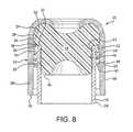
- FIG. 8is a view similar to FIG. 3 of an alternate embodiment of the disclosed technology having a threaded closure for receiving a threaded vessel neck.
- FIG. 9is an isolated cutaway view of a pusher according to an alternate embodiment of the disclosed technology.
- a closure generally indicated as 10is shown that is useful for closing an opening 12 of a generally cylindrical neck 14 of a vessel 16 .
- the closure 10includes a stopper 18 , a shield 20 , and a pusher 22 .
- the vessel 16 illustrated in the Figuresis a medical sample collection tube, one example of which is an evacuated blood collection tube, described for example in connection with FIG. 3 of U.S. Pat. No. 4,741,446.
- the neck 14has substantially the same diameter as the body 24 of the vessel.
- a jaris another example of a vessel having a neck that is the same or nearly the same diameter as the body of the vessel.
- a neck having a smaller diameter than the body of the vesselis also contemplated, for example, a bottle.
- a neck having a larger diameter than the body of the vesselis also contemplated.
- the stopper 18is configured to seat at least partially within the vessel 16 opening 12 to isolate the contents of the vessel 16 from the ambient environment.
- the stopper 18includes a body portion 26 configured to seat at least partially within the opening 12 .
- the stopper 18 as illustrated in FIG. 3includes a head portion 28 secured to (and as illustrated integral with) the body portion 26 .
- the head portion 28is configured to extend at least partially outside the opening 12 when the body portion is seated at least partially within the opening 12 .
- the head portion 28can include a stopper abutment 30 extending radially outward from the body portion 26 of the stopper 18 .
- the pusher 22 of the shield 20bears against the stopper abutment 30 to assist in pushing the stopper 18 out of the opening 12 .
- the stopper abutment 30could abut the lip 32 of the neck 14 , this is not required, and the abutment 30 alternatively can be out of contact with the lip 32 .
- the stopper abutment 30can be a circumferentially extending flange, as illustrated in FIGS. 3 and 4 .
- a step 80is provided to prevent any portion of the pusher 22 from sliding radially inward of the abutment 30 .
- the step 80 of this embodimentoptionally can act as a stop to limit the travel of the stopper 18 into the opening 12 by abutting against the lip 32 of the neck 14 when the stopper 18 is fully inserted.
- the shield 20can include a recess 34 configured to receive at least a portion of the stopper 18 .
- the recess 34 of the shield 20can be at least partially defined by the inner surface 36 of a skirt 38 .
- the skirt 38can be configured to be positioned outside the generally cylindrical neck 14 when the stopper 18 is seated in the vessel opening 12 .
- the skirt 38is spaced radially outside the neck 14 , providing a generally annular space between the skirt 38 and the neck 14 .
- the stopper 18is maintained in its seated position in the opening 12 by friction between the neck 14 and the stopper 18 .
- the body portion 26 of the stopper 18is larger in nominal diameter (when unconfined) than the inner surface 40 of the neck 14 , providing an interference fit of the stopper 18 within the neck 14 that presses the stopper 18 into intimate contact with the inner surface 40 .
- the skirt 38optionally can be threaded, as with a thread 42 , to receive corresponding threads 44 of the neck 14 of a vessel 16 .
- two, three, four, or more generally parallel helical threadscan be provided in the skirt 38 and the neck 14 to allow the shield 20 to be lifted from the neck 14 with relatively few turns, optionally a partial turn, of the skirt 38 with respect to the neck 14 .
- the threaded engagement of the skirt 38 and the neck 14can provide a mechanical advantage for seating and unseating the stopper 18 in the opening 12 or seating the stopper 18 in the recess 34 , though engaged threads might prevent or slow down the operation of removing the stopper 18 by a user holding the vessel 16 in one hand and lifting the stopper by manipulating the shield 20 with the thumb of the same hand. It is contemplated that some users or applications will favor a threaded closure and others will not.
- the stopper 18can be recessed into the shield recess. This recessed configuration is illustrated in FIG. 3 , showing the lower end 46 of the stopper 18 recessed or spaced into the opening 48 of the shield 20 .
- the pusher 22 when in use as shown in FIG. 6can extend radially (i.e. at an angle greater than zero from vertical as shown in FIG. 3 ) from the inner surface 36 of the skirt 38 into the recess 34 of the shield 20 .
- the pusher 22can be configured to extend axially into the recess 34 (i.e. directly or obliquely upward, as shown in FIG. 3 ).
- the pusher 22has a distal portion 50 and a proximal portion 52 , with respect to the inner surface 36 of the skirt 38 .
- the proximal portion 52can be connected to, and as illustrated is integral with, the inner surface 36 of the skirt 38 .
- the distal portion 50 of the pusher 22can extend axially into the recess 34 (i.e. straight or obliquely upward in the orientation of FIG. 3 ).
- the pusher 22can be provided in the form of a web 53 , illustrated as a generally frustoconical or cone-shaped web having an outer surface 54 facing axially out and an inner surface 56 facing axially in, as illustrated in the Figures.
- the pusher outer surface 54optionally can have at least one raised projection 58 , or multiple raised projections 58 as shown in FIG. 9 , extending out from the surface 54 .
- the raised projections 58can be ribs, though they could also be shaped as corrugations, raised compact spots, or provided in other configurations.
- the projections such as 58are contemplated to minimize the surface contact area between the head portion 28 of the stopper 18 and the outer surface 54 when the stopper 18 is inserted into the recess 34 when assembling the closure 10 .
- the rib-shaped projections 58 as illustratedalso stiffen the pusher 22 in the illustrated embodiment.
- the pusher 22can be one or more, alternatively two or more, circumferentially spaced ribs such as 58 without providing a circumferentially extending web 53 to join them together.
- the presence of a web 53can function to orient the ribs such as 58 , particularly when shifted between their first and second positions as described below.
- the distal portion 50 of the pusher 22engages the abutment 30 of the stopper 18 when the closure 10 is assembled as in FIG. 3 .
- the pusher 22is configured to push the stopper 18 out of the opening 12 when the shield 20 is withdrawn axially (i.e. moved upward as shown in FIG. 3 ) from the generally cylindrical neck 14 of the vessel 16 , for example when removing the closure 10 from the vessel opening 12 .
- FIG. 6shows that the pusher 22 can also extend circumferentially within the inner surface 36 of the skirt 38 .
- the pusher 22can be movable between a first position, illustrated in FIG. 6 , extending axially outward (i.e. the distal portion 50 extending toward the opening 48 vertically or obliquely) from the inner surface 36 of the skirt 38 and a second position, illustrated in FIG. 4 , extending axially inward from the inner surface 36 of the skirt 38 .
- a first positionillustrated in FIG. 6
- a second positionillustrated in FIG. 4
- Another aspect of the inventionis a method of making and assembling a closure 10 configured to close the vessel opening 12 .
- the methodcan be carried out as follows.
- a stopper 18 , shield 20 , and pusher 22 as previously described, or variations upon them,can be provided.
- the stopper 18can be made conventionally, as by injection molding a resilient, injection moldable material.
- An example of suitable material for the stopper 18is butyl rubber.
- the pusher 22can be located within, optionally integral with, the shield 20 as previously described.
- An integral pusher 22 and shield 20can be made, for example, by injection molding the part 20 / 22 shown in FIG. 6 , using the two-core injection mold shown schematically in FIG. 7 .
- the moldincludes a mold cavity 62 , an inner core 64 , and an outer core 66 .
- the mold cavity 62can form the exterior 68 of the shield 20 .
- the mostly cylindrical inner core 64can form the inner surface 56 of the pusher 22 and most of the inner surface 36 of the skirt 38 .
- the mostly annular outer core 66can form the outer surface 54 of the pusher 22 and the remainder of the inner surface 36 of the skirt 38 lying below the pusher 22 as illustrated in FIG. 7 .
- An example of suitable material for the integral pusher 22 and shield 20is a copolymer of polyethylene and polypropylene.
- the inner and outer cores 64 and 66can be integral, defining a one-piece core.
- the pusher distal portion 50is in a first position extending axially outward from the inner surface 36 of the skirt 38 .
- the first position of the pusher distal portion 50is contemplated to facilitate removing the cores 64 and 66 , as the removal of the outer core 66 opens a space between the inner core 64 and the just-formed skirt 38 .
- the pusher 22can then sweep through the space that has been opened and fold against the inner surface 36 of the skirt 38 as the inner core 64 is withdrawn from the cavity 62 .
- the integral core 64 / 66can be withdrawn, again folding the distal portion 50 against the inner surface 56 but increasing the surface area of contact between the pusher 22 and the portions of the core 64 / 66 that form it, compared to a two-part core.
- the pusher 22can alternatively be molded in its second position extending axially inward into the recess 34 of the shield 20 . If this is done, however, the withdrawal of the inner core portion forming the portion of the recess 34 above the pusher 22 would tend to invert the pusher 22 to its first position.
- the combined shield 20 and pusher 22can be made by a method such as lost-wax casting that does not require a core to be withdrawn in one piece.
- more complex cores having outer portions that are withdrawn radially inward after withdrawing an inner portion axiallyare also contemplated.
- the pusher distal portion 50can be displaced inward into the recess 34 of the shield 20 to a second position, illustrated for example in FIG. 3 , extending axially inward (either obliquely or straight inward) from the inner surface 36 of the skirt 38 .
- the pusher 22 in the first positioncan be displaced to the second position by inserting a tool 70 , as shown in FIG. 9 , into the recess 34 and bearing the tool 70 against the outer surface 54 of the pusher 22 , inverting the cone defined by the pusher 22 to its second position.
- the tool 70can then be withdrawn.
- the pusher 22 in the first positioncan be displaced to the second position by inserting the stopper 18 into the recess 34 , causing the head portion 28 of the stopper 18 to function in the same manner as the tool 70 , except that the stopper 18 can be inserted further into the recess 34 of the shield 20 to a seated position, shown in FIG. 3 , after the pusher distal portion 50 is displaced to its second position.
- the stopper 18can be inserted into the opening 12 before or after the stopper 18 is seated in the recess 34 .
- the distal portion 50 of the pusher 22engages the stopper 18 and is positioned to push the stopper 18 out of the opening 12 when the shield 20 is withdrawn axially (moved upward as shown in FIG. 3 ) from the vessel opening 12 .
Landscapes
- Health & Medical Sciences (AREA)
- Life Sciences & Earth Sciences (AREA)
- Engineering & Computer Science (AREA)
- Hematology (AREA)
- General Health & Medical Sciences (AREA)
- Animal Behavior & Ethology (AREA)
- Public Health (AREA)
- Biomedical Technology (AREA)
- Heart & Thoracic Surgery (AREA)
- Medical Informatics (AREA)
- Molecular Biology (AREA)
- Surgery (AREA)
- Biophysics (AREA)
- Physics & Mathematics (AREA)
- Pathology (AREA)
- Veterinary Medicine (AREA)
- Chemical & Material Sciences (AREA)
- Mechanical Engineering (AREA)
- Analytical Chemistry (AREA)
- Clinical Laboratory Science (AREA)
- Chemical Kinetics & Catalysis (AREA)
- Manufacturing & Machinery (AREA)
- Closures For Containers (AREA)
- Containers And Packaging Bodies Having A Special Means To Remove Contents (AREA)
Abstract
Description
| 10 | |||
| 12 | Opening (of 14) | ||
| 14 | Neck (of 16) | ||
| 16 | |||
| 18 | |||
| 20 | |||
| 22 | |||
| 24 | Body (of 16) | ||
| 26 | Body portion (of 18) | ||
| 28 | Head portion (of 18) | ||
| 30 | Abutment (of 18) | ||
| 32 | Lip (of 14) | ||
| 34 | Recess (of 20) | ||
| 36 | Inner surface (of 38) | ||
| 38 | Skirt (of 20) | ||
| 40 | Inner surface (of 14) | ||
| 42 | Thread (of 38) | ||
| 44 | Thread (of 14) | ||
| 46 | Lower end (of 18) | ||
| 48 | Opening (of 20) | ||
| 50 | Distal portion (of 22) | ||
| 52 | Proximal portion (of 22) | ||
| 53 | Web (of 22) | ||
| 54 | Outer surface (of 22) | ||
| 56 | Inner surface (of 22) | ||
| 58 | Raised projection (of 56) | ||
| 62 | |||
| 64 | |||
| 66 | |||
| 68 | Exterior (of 20) | ||
| 70 | |||
| 80 | Step | ||
Claims (19)
Priority Applications (1)
| Application Number | Priority Date | Filing Date | Title |
|---|---|---|---|
| US13/520,037US8627970B2 (en) | 2010-01-06 | 2011-01-06 | Closure with shield, stopper, and pusher, and method for making the same |
Applications Claiming Priority (3)
| Application Number | Priority Date | Filing Date | Title |
|---|---|---|---|
| US29253310P | 2010-01-06 | 2010-01-06 | |
| PCT/US2011/020357WO2011085089A2 (en) | 2010-01-06 | 2011-01-06 | Closure with shield, stopper, and pusher, and method for making the same |
| US13/520,037US8627970B2 (en) | 2010-01-06 | 2011-01-06 | Closure with shield, stopper, and pusher, and method for making the same |
Publications (2)
| Publication Number | Publication Date |
|---|---|
| US20130140262A1 US20130140262A1 (en) | 2013-06-06 |
| US8627970B2true US8627970B2 (en) | 2014-01-14 |
Family
ID=44306139
Family Applications (1)
| Application Number | Title | Priority Date | Filing Date |
|---|---|---|---|
| US13/520,037ActiveUS8627970B2 (en) | 2010-01-06 | 2011-01-06 | Closure with shield, stopper, and pusher, and method for making the same |
Country Status (3)
| Country | Link |
|---|---|
| US (1) | US8627970B2 (en) |
| EP (1) | EP2521675B1 (en) |
| WO (1) | WO2011085089A2 (en) |
Cited By (3)
| Publication number | Priority date | Publication date | Assignee | Title |
|---|---|---|---|---|
| US20130075405A1 (en)* | 2011-09-27 | 2013-03-28 | Kabushiki Kaisha Toyota Jidoshokki | Port closing device for compressor |
| US20170121163A1 (en)* | 2014-06-18 | 2017-05-04 | Antonio Mutterle | Method for sealingly closing a bottle and associated sealingly closed bottle |
| US11491179B2 (en) | 2017-04-12 | 2022-11-08 | Urigen Pharmaceuticals, Inc. | Article of manufacture comprising local anesthetic, buffer, and glycosaminoglycan in syringe with improved stability |
Families Citing this family (4)
| Publication number | Priority date | Publication date | Assignee | Title |
|---|---|---|---|---|
| USD693941S1 (en)* | 2012-04-12 | 2013-11-19 | Becton Dickinson And Company | Cap portion of a vial |
| USD690827S1 (en)* | 2012-04-12 | 2013-10-01 | Becton Dickinson And Company | Cap portion of a vial |
| FR3035376B1 (en)* | 2015-04-27 | 2017-05-05 | Mbf Plastiques | DEVICE FOR MAINTAINING AND REMOVING A CAP ENGAGED IN A BOTTLE COLLAR. |
| FR3037569B1 (en)* | 2015-06-18 | 2017-07-21 | Aptar France Sas | AXIAL MAGNETIC ATTRACTION DEVICE. |
Citations (7)
| Publication number | Priority date | Publication date | Assignee | Title |
|---|---|---|---|---|
| EP0366617A2 (en) | 1988-09-26 | 1990-05-02 | CMB ITALCAPS TECHNOLOGY s.r.l. | Tamper-evident composite snap closure |
| US5361921A (en) | 1993-06-29 | 1994-11-08 | Becton Dickinson And Company | Combination stopper-shield closure |
| US5718348A (en)* | 1996-09-12 | 1998-02-17 | Comar, Inc. | Overcap assembly for gear finish vial |
| US6602206B1 (en) | 1999-08-18 | 2003-08-05 | Becton, Dickinson And Company | Stopper-shield assembly |
| US20070272648A1 (en)* | 2003-06-03 | 2007-11-29 | Keiji Hamamoto | Container Cap |
| US20070272645A1 (en)* | 2004-07-29 | 2007-11-29 | Kazumasa Ito | Artificial Nipple, Infant Feeding Device, and Artificial Nipple Manufacturing Method |
| US20090308184A1 (en) | 2008-03-05 | 2009-12-17 | Becton, Dickinson And Company | Co-Molded Pierceable Stopper and Method for Making the Same |
- 2011
- 2011-01-06USUS13/520,037patent/US8627970B2/enactiveActive
- 2011-01-06EPEP11732135.6Apatent/EP2521675B1/enactiveActive
- 2011-01-06WOPCT/US2011/020357patent/WO2011085089A2/enactiveApplication Filing
Patent Citations (7)
| Publication number | Priority date | Publication date | Assignee | Title |
|---|---|---|---|---|
| EP0366617A2 (en) | 1988-09-26 | 1990-05-02 | CMB ITALCAPS TECHNOLOGY s.r.l. | Tamper-evident composite snap closure |
| US5361921A (en) | 1993-06-29 | 1994-11-08 | Becton Dickinson And Company | Combination stopper-shield closure |
| US5718348A (en)* | 1996-09-12 | 1998-02-17 | Comar, Inc. | Overcap assembly for gear finish vial |
| US6602206B1 (en) | 1999-08-18 | 2003-08-05 | Becton, Dickinson And Company | Stopper-shield assembly |
| US20070272648A1 (en)* | 2003-06-03 | 2007-11-29 | Keiji Hamamoto | Container Cap |
| US20070272645A1 (en)* | 2004-07-29 | 2007-11-29 | Kazumasa Ito | Artificial Nipple, Infant Feeding Device, and Artificial Nipple Manufacturing Method |
| US20090308184A1 (en) | 2008-03-05 | 2009-12-17 | Becton, Dickinson And Company | Co-Molded Pierceable Stopper and Method for Making the Same |
Non-Patent Citations (2)
| Title |
|---|
| International Search Report and Written Opinion for International Patent Application No. PCT/US2011/020357 mailed Sep. 7, 2011. |
| PCT, Notification Concerning Transmittal of International Preliminary Report on Patentability, in international application No. PCT/US2011/020357, dated Jul. 19, 2012. |
Cited By (5)
| Publication number | Priority date | Publication date | Assignee | Title |
|---|---|---|---|---|
| US20130075405A1 (en)* | 2011-09-27 | 2013-03-28 | Kabushiki Kaisha Toyota Jidoshokki | Port closing device for compressor |
| US8826941B2 (en)* | 2011-09-27 | 2014-09-09 | Kabushiki Kaisha Toyota Jidoshokki | Port closing device for compressor |
| US20170121163A1 (en)* | 2014-06-18 | 2017-05-04 | Antonio Mutterle | Method for sealingly closing a bottle and associated sealingly closed bottle |
| US10843913B2 (en)* | 2014-06-18 | 2020-11-24 | Altergon Sa | Method for sealingly closing a bottle and associated sealingly closed bottle |
| US11491179B2 (en) | 2017-04-12 | 2022-11-08 | Urigen Pharmaceuticals, Inc. | Article of manufacture comprising local anesthetic, buffer, and glycosaminoglycan in syringe with improved stability |
Also Published As
| Publication number | Publication date |
|---|---|
| WO2011085089A2 (en) | 2011-07-14 |
| US20130140262A1 (en) | 2013-06-06 |
| EP2521675A2 (en) | 2012-11-14 |
| WO2011085089A3 (en) | 2011-11-03 |
| EP2521675B1 (en) | 2014-05-14 |
| EP2521675A4 (en) | 2013-06-05 |
Similar Documents
| Publication | Publication Date | Title |
|---|---|---|
| US8627970B2 (en) | Closure with shield, stopper, and pusher, and method for making the same | |
| US20150321804A1 (en) | Child-resistant cap and container assembly | |
| US20210276769A1 (en) | Child-Resistant Closure | |
| US11338088B2 (en) | Venting safety closure | |
| DK173621B1 (en) | Gasket-free closure for carbonated beverage container | |
| EP3647223B1 (en) | Plastic cap and manufacturing method thereof | |
| JP2013525219A (en) | Bottle accessories for attaching a drinking mouth that can be retracted using a cap to a bottle | |
| US20170334112A1 (en) | Method of Making A Bayonet Sealing Closure For Containers and Lids | |
| US20060081649A1 (en) | Pourer | |
| CN107000903B (en) | For the lid of container and the packaging including such lid | |
| US7513388B2 (en) | Retractable straw device | |
| JP7407717B2 (en) | container | |
| JP2018162097A (en) | Synthetic resin cap and cap unit | |
| JP6452252B2 (en) | container | |
| KR102096794B1 (en) | One-touch opening and closing structure of stopper and container | |
| CN113646237B (en) | Closure for a container | |
| EP1394061A2 (en) | Sealing closure plug | |
| JP2019529267A (en) | Cap and neck assembly for food packaging containers | |
| RU2692820C2 (en) | Container with container head made as single part | |
| JP2002370755A (en) | Tube container | |
| JP2005193942A (en) | Screw type sealing mechanism with soft resin | |
| KR100919774B1 (en) | Vacuum blood collection tube | |
| JP2022164112A (en) | Cap and method of making the cap | |
| KR20140111408A (en) | Residue improved tube container | |
| JP2550710Y2 (en) | Two-liquid mixing container |
Legal Events
| Date | Code | Title | Description |
|---|---|---|---|
| AS | Assignment | Owner name:CV HOLDINGS, LLC, NEW YORK Free format text:ASSIGNMENT OF ASSIGNORS INTEREST;ASSIGNOR:BUCHOLTZ, MICHAEL;REEL/FRAME:028480/0746 Effective date:20120702 Owner name:CSP TECHNOLOGIES, INC., ALABAMA Free format text:ASSIGNMENT OF ASSIGNORS INTEREST;ASSIGNOR:CV HOLDINGS, LLC;REEL/FRAME:028481/0288 Effective date:20120702 | |
| AS | Assignment | Owner name:CAPITOL MEDICAL DEVICES, INC., ALABAMA Free format text:ASSIGNMENT OF ASSIGNORS INTEREST;ASSIGNOR:CSP TECHNOLOGIES, INC.;REEL/FRAME:031398/0759 Effective date:20131008 | |
| STCF | Information on status: patent grant | Free format text:PATENTED CASE | |
| AS | Assignment | Owner name:CYPRIUM INVESTORS IV LP, AS ADMINISTRATIVE AGENT, Free format text:SECURITY AGREEMENT;ASSIGNOR:CAPITOL MEDICAL DEVICES, INC.;REEL/FRAME:031968/0285 Effective date:20131227 | |
| AS | Assignment | Owner name:CAPITOL MEDICAL DEVICES, INC., ALABAMA Free format text:ASSIGNMENT OF ASSIGNORS INTEREST;ASSIGNOR:CSP TECHNOLOGIES, INC.;REEL/FRAME:032047/0788 Effective date:20131008 Owner name:LLC, CV HOLDINGS, NEW YORK Free format text:ASSIGNMENT OF ASSIGNORS INTEREST;ASSIGNOR:BUCHOLTZ, MICHAEL;REEL/FRAME:032047/0634 Effective date:20120702 Owner name:CSP TECHNOLOGIES, INC., ALABAMA Free format text:ASSIGNMENT OF ASSIGNORS INTEREST;ASSIGNOR:CV HOLDINGS, LLC;REEL/FRAME:032047/0652 Effective date:20120702 | |
| AS | Assignment | Owner name:SIO2 MEDICAL PRODUCTS, INC., ALABAMA Free format text:ASSIGNMENT OF ASSIGNORS INTEREST;ASSIGNOR:CAPITOL MEDICAL DEVICES, INC.;REEL/FRAME:034289/0876 Effective date:20141126 | |
| FEPP | Fee payment procedure | Free format text:PAT HOLDER NO LONGER CLAIMS SMALL ENTITY STATUS, ENTITY STATUS SET TO UNDISCOUNTED (ORIGINAL EVENT CODE: STOL); ENTITY STATUS OF PATENT OWNER: LARGE ENTITY | |
| SULP | Surcharge for late payment | ||
| AS | Assignment | Owner name:CAPITOL PLASTIC PRODUCTS, L.L.C., NEW YORK Free format text:RELEASE BY SECURED PARTY;ASSIGNOR:CYPRIUM INVESTORS IV LP;REEL/FRAME:035105/0796 Effective date:20150106 Owner name:CAPITOL MEDICAL DEVICES, INC., ALABAMA Free format text:RELEASE BY SECURED PARTY;ASSIGNOR:CYPRIUM INVESTORS IV LP;REEL/FRAME:035105/0796 Effective date:20150106 Owner name:CAPITOL CUPS, INC., NEW YORK Free format text:RELEASE BY SECURED PARTY;ASSIGNOR:CYPRIUM INVESTORS IV LP;REEL/FRAME:035105/0796 Effective date:20150106 Owner name:CV PARTNERS, ALABAMA Free format text:RELEASE BY SECURED PARTY;ASSIGNOR:CYPRIUM INVESTORS IV LP;REEL/FRAME:035105/0796 Effective date:20150106 Owner name:CV HOLDINGS, L.L.C, NEW YORK Free format text:RELEASE BY SECURED PARTY;ASSIGNOR:CYPRIUM INVESTORS IV LP;REEL/FRAME:035105/0796 Effective date:20150106 Owner name:CSP TECHNOLOGIES, INC., NEW YORK Free format text:RELEASE BY SECURED PARTY;ASSIGNOR:CYPRIUM INVESTORS IV LP;REEL/FRAME:035105/0796 Effective date:20150106 Owner name:TOTAL INNOVATIVE PACKAGING, INC., NEW YORK Free format text:RELEASE BY SECURED PARTY;ASSIGNOR:CYPRIUM INVESTORS IV LP;REEL/FRAME:035105/0796 Effective date:20150106 | |
| AS | Assignment | Owner name:SIO2 MEDICAL PRODUCTS, INC., ALABAMA Free format text:SECURITY AGREEMENT;ASSIGNOR:THE TEACHERS' RETIREMENT SYSTEM OF ALABAMA;REEL/FRAME:039431/0327 Effective date:20150612 | |
| AS | Assignment | Owner name:THE TEACHERS' RETIREMENT SYSTEM OF ALABAMA, ALABAMA Free format text:CORRECTIVE ASSIGNMENT TO CORRECT THE ASSIGNEE AND ASSIGNOR NAMES AND UPDATE TO PROPERTY NUMBERS PREVIOUSLY OMITTED PREVIOUSLY RECORDED ON REEL 039431 FRAME 0327. ASSIGNOR(S) HEREBY CONFIRMS THE SECURITY AGREEMENT;ASSIGNOR:SIO2 MEDICAL PRODUCTS, INC.;REEL/FRAME:040002/0514 Effective date:20150612 Owner name:THE TEACHERS' RETIREMENT SYSTEM OF ALABAMA, ALABAM Free format text:CORRECTIVE ASSIGNMENT TO CORRECT THE ASSIGNEE AND ASSIGNOR NAMES AND UPDATE TO PROPERTY NUMBERS PREVIOUSLY OMITTED PREVIOUSLY RECORDED ON REEL 039431 FRAME 0327. ASSIGNOR(S) HEREBY CONFIRMS THE SECURITY AGREEMENT;ASSIGNOR:SIO2 MEDICAL PRODUCTS, INC.;REEL/FRAME:040002/0514 Effective date:20150612 | |
| FPAY | Fee payment | Year of fee payment:4 | |
| MAFP | Maintenance fee payment | Free format text:PAYMENT OF MAINTENANCE FEE, 8TH YEAR, LARGE ENTITY (ORIGINAL EVENT CODE: M1552); ENTITY STATUS OF PATENT OWNER: LARGE ENTITY Year of fee payment:8 | |
| AS | Assignment | Owner name:OAKTREE FUND ADMINISTRATION, LLC, CALIFORNIA Free format text:SECURITY INTEREST;ASSIGNOR:SIO2 MEDICAL PRODUCTS, INC.;REEL/FRAME:058562/0158 Effective date:20211221 | |
| AS | Assignment | Owner name:SALZUFER HOLDING INC., AS ADMINISTRATIVE AGENT, FLORIDA Free format text:SECURITY INTEREST;ASSIGNOR:SIO2 MEDICAL PRODUCTS, INC.;REEL/FRAME:062094/0121 Effective date:20221207 | |
| AS | Assignment | Owner name:SIO2 MEDICAL PRODUCTS, INC., ALABAMA Free format text:RELEASE BY SECURED PARTY;ASSIGNOR:THE TEACHERS RETIREMENT SYSTEM OF ALABAMA;REEL/FRAME:063216/0233 Effective date:20211220 | |
| AS | Assignment | Owner name:SIO2 MEDICAL PRODUCTS, LLC, ALABAMA Free format text:CHANGE OF NAME;ASSIGNOR:SIO2 MEDICAL PRODUCTS, INC.;REEL/FRAME:068839/0691 Effective date:20240830 | |
| FEPP | Fee payment procedure | Free format text:MAINTENANCE FEE REMINDER MAILED (ORIGINAL EVENT CODE: REM.); ENTITY STATUS OF PATENT OWNER: LARGE ENTITY |