US8627908B2 - Semi-autonomous vehicle providing an auxiliary power supply - Google Patents
Semi-autonomous vehicle providing an auxiliary power supplyDownload PDFInfo
- Publication number
- US8627908B2 US8627908B2US13/016,969US201113016969AUS8627908B2US 8627908 B2US8627908 B2US 8627908B2US 201113016969 AUS201113016969 AUS 201113016969AUS 8627908 B2US8627908 B2US 8627908B2
- Authority
- US
- United States
- Prior art keywords
- vehicle
- semi
- voltage
- autonomous vehicle
- storage system
- Prior art date
- Legal status (The legal status is an assumption and is not a legal conclusion. Google has not performed a legal analysis and makes no representation as to the accuracy of the status listed.)
- Active, expires
Links
Images


Classifications
- B—PERFORMING OPERATIONS; TRANSPORTING
- B62—LAND VEHICLES FOR TRAVELLING OTHERWISE THAN ON RAILS
- B62D—MOTOR VEHICLES; TRAILERS
- B62D59/00—Trailers with driven ground wheels or the like
- B62D59/04—Trailers with driven ground wheels or the like driven from propulsion unit on trailer
- B—PERFORMING OPERATIONS; TRANSPORTING
- B60—VEHICLES IN GENERAL
- B60L—PROPULSION OF ELECTRICALLY-PROPELLED VEHICLES; SUPPLYING ELECTRIC POWER FOR AUXILIARY EQUIPMENT OF ELECTRICALLY-PROPELLED VEHICLES; ELECTRODYNAMIC BRAKE SYSTEMS FOR VEHICLES IN GENERAL; MAGNETIC SUSPENSION OR LEVITATION FOR VEHICLES; MONITORING OPERATING VARIABLES OF ELECTRICALLY-PROPELLED VEHICLES; ELECTRIC SAFETY DEVICES FOR ELECTRICALLY-PROPELLED VEHICLES
- B60L15/00—Methods, circuits, or devices for controlling the traction-motor speed of electrically-propelled vehicles
- B60L15/42—Adaptation of control equipment on vehicle for actuation from alternative parts of the vehicle or from alternative vehicles of the same vehicle train
- B—PERFORMING OPERATIONS; TRANSPORTING
- B60—VEHICLES IN GENERAL
- B60W—CONJOINT CONTROL OF VEHICLE SUB-UNITS OF DIFFERENT TYPE OR DIFFERENT FUNCTION; CONTROL SYSTEMS SPECIALLY ADAPTED FOR HYBRID VEHICLES; ROAD VEHICLE DRIVE CONTROL SYSTEMS FOR PURPOSES NOT RELATED TO THE CONTROL OF A PARTICULAR SUB-UNIT
- B60W10/00—Conjoint control of vehicle sub-units of different type or different function
- B60W10/04—Conjoint control of vehicle sub-units of different type or different function including control of propulsion units
- B60W10/08—Conjoint control of vehicle sub-units of different type or different function including control of propulsion units including control of electric propulsion units, e.g. motors or generators
- B—PERFORMING OPERATIONS; TRANSPORTING
- B60—VEHICLES IN GENERAL
- B60W—CONJOINT CONTROL OF VEHICLE SUB-UNITS OF DIFFERENT TYPE OR DIFFERENT FUNCTION; CONTROL SYSTEMS SPECIALLY ADAPTED FOR HYBRID VEHICLES; ROAD VEHICLE DRIVE CONTROL SYSTEMS FOR PURPOSES NOT RELATED TO THE CONTROL OF A PARTICULAR SUB-UNIT
- B60W10/00—Conjoint control of vehicle sub-units of different type or different function
- B60W10/18—Conjoint control of vehicle sub-units of different type or different function including control of braking systems
- B—PERFORMING OPERATIONS; TRANSPORTING
- B60—VEHICLES IN GENERAL
- B60W—CONJOINT CONTROL OF VEHICLE SUB-UNITS OF DIFFERENT TYPE OR DIFFERENT FUNCTION; CONTROL SYSTEMS SPECIALLY ADAPTED FOR HYBRID VEHICLES; ROAD VEHICLE DRIVE CONTROL SYSTEMS FOR PURPOSES NOT RELATED TO THE CONTROL OF A PARTICULAR SUB-UNIT
- B60W10/00—Conjoint control of vehicle sub-units of different type or different function
- B60W10/20—Conjoint control of vehicle sub-units of different type or different function including control of steering systems
- B—PERFORMING OPERATIONS; TRANSPORTING
- B60—VEHICLES IN GENERAL
- B60W—CONJOINT CONTROL OF VEHICLE SUB-UNITS OF DIFFERENT TYPE OR DIFFERENT FUNCTION; CONTROL SYSTEMS SPECIALLY ADAPTED FOR HYBRID VEHICLES; ROAD VEHICLE DRIVE CONTROL SYSTEMS FOR PURPOSES NOT RELATED TO THE CONTROL OF A PARTICULAR SUB-UNIT
- B60W30/00—Purposes of road vehicle drive control systems not related to the control of a particular sub-unit, e.g. of systems using conjoint control of vehicle sub-units
- B60W30/18—Propelling the vehicle
- G—PHYSICS
- G05—CONTROLLING; REGULATING
- G05D—SYSTEMS FOR CONTROLLING OR REGULATING NON-ELECTRIC VARIABLES
- G05D1/00—Control of position, course, altitude or attitude of land, water, air or space vehicles, e.g. using automatic pilots
- G05D1/20—Control system inputs
- G05D1/24—Arrangements for determining position or orientation
- G05D1/244—Arrangements for determining position or orientation using passive navigation aids external to the vehicle, e.g. markers, reflectors or magnetic means
- G—PHYSICS
- G05—CONTROLLING; REGULATING
- G05D—SYSTEMS FOR CONTROLLING OR REGULATING NON-ELECTRIC VARIABLES
- G05D1/00—Control of position, course, altitude or attitude of land, water, air or space vehicles, e.g. using automatic pilots
- G05D1/60—Intended control result
- G05D1/69—Coordinated control of the position or course of two or more vehicles
- G05D1/695—Coordinated control of the position or course of two or more vehicles for maintaining a fixed relative position of the vehicles, e.g. for convoy travelling or formation flight
- G05D1/696—Coordinated control of the position or course of two or more vehicles for maintaining a fixed relative position of the vehicles, e.g. for convoy travelling or formation flight involving a plurality of vehicles coupled together
- B—PERFORMING OPERATIONS; TRANSPORTING
- B60—VEHICLES IN GENERAL
- B60L—PROPULSION OF ELECTRICALLY-PROPELLED VEHICLES; SUPPLYING ELECTRIC POWER FOR AUXILIARY EQUIPMENT OF ELECTRICALLY-PROPELLED VEHICLES; ELECTRODYNAMIC BRAKE SYSTEMS FOR VEHICLES IN GENERAL; MAGNETIC SUSPENSION OR LEVITATION FOR VEHICLES; MONITORING OPERATING VARIABLES OF ELECTRICALLY-PROPELLED VEHICLES; ELECTRIC SAFETY DEVICES FOR ELECTRICALLY-PROPELLED VEHICLES
- B60L2200/00—Type of vehicles
- B60L2200/28—Trailers
- B—PERFORMING OPERATIONS; TRANSPORTING
- B60—VEHICLES IN GENERAL
- B60L—PROPULSION OF ELECTRICALLY-PROPELLED VEHICLES; SUPPLYING ELECTRIC POWER FOR AUXILIARY EQUIPMENT OF ELECTRICALLY-PROPELLED VEHICLES; ELECTRODYNAMIC BRAKE SYSTEMS FOR VEHICLES IN GENERAL; MAGNETIC SUSPENSION OR LEVITATION FOR VEHICLES; MONITORING OPERATING VARIABLES OF ELECTRICALLY-PROPELLED VEHICLES; ELECTRIC SAFETY DEVICES FOR ELECTRICALLY-PROPELLED VEHICLES
- B60L2200/00—Type of vehicles
- B60L2200/30—Trolleys
- B—PERFORMING OPERATIONS; TRANSPORTING
- B60—VEHICLES IN GENERAL
- B60W—CONJOINT CONTROL OF VEHICLE SUB-UNITS OF DIFFERENT TYPE OR DIFFERENT FUNCTION; CONTROL SYSTEMS SPECIALLY ADAPTED FOR HYBRID VEHICLES; ROAD VEHICLE DRIVE CONTROL SYSTEMS FOR PURPOSES NOT RELATED TO THE CONTROL OF A PARTICULAR SUB-UNIT
- B60W2300/00—Indexing codes relating to the type of vehicle
- B60W2300/14—Tractor-trailers, i.e. combinations of a towing vehicle and one or more towed vehicles, e.g. caravans; Road trains
- G—PHYSICS
- G05—CONTROLLING; REGULATING
- G05D—SYSTEMS FOR CONTROLLING OR REGULATING NON-ELECTRIC VARIABLES
- G05D2105/00—Specific applications of the controlled vehicles
- G05D2105/20—Specific applications of the controlled vehicles for transportation
- G05D2105/22—Specific applications of the controlled vehicles for transportation of humans
- G—PHYSICS
- G05—CONTROLLING; REGULATING
- G05D—SYSTEMS FOR CONTROLLING OR REGULATING NON-ELECTRIC VARIABLES
- G05D2105/00—Specific applications of the controlled vehicles
- G05D2105/45—Specific applications of the controlled vehicles for manufacturing, maintenance or repairing
- G05D2105/47—Specific applications of the controlled vehicles for manufacturing, maintenance or repairing for maintenance or repairing, e.g. fuelling or battery replacement
- G—PHYSICS
- G05—CONTROLLING; REGULATING
- G05D—SYSTEMS FOR CONTROLLING OR REGULATING NON-ELECTRIC VARIABLES
- G05D2107/00—Specific environments of the controlled vehicles
- G05D2107/10—Outdoor regulated spaces
- G05D2107/13—Spaces reserved for vehicle traffic, e.g. roads, regulated airspace or regulated waters
- G—PHYSICS
- G05—CONTROLLING; REGULATING
- G05D—SYSTEMS FOR CONTROLLING OR REGULATING NON-ELECTRIC VARIABLES
- G05D2109/00—Types of controlled vehicles
- G05D2109/10—Land vehicles
- G—PHYSICS
- G05—CONTROLLING; REGULATING
- G05D—SYSTEMS FOR CONTROLLING OR REGULATING NON-ELECTRIC VARIABLES
- G05D2111/00—Details of signals used for control of position, course, altitude or attitude of land, water, air or space vehicles
- G05D2111/30—Radio signals
- Y—GENERAL TAGGING OF NEW TECHNOLOGICAL DEVELOPMENTS; GENERAL TAGGING OF CROSS-SECTIONAL TECHNOLOGIES SPANNING OVER SEVERAL SECTIONS OF THE IPC; TECHNICAL SUBJECTS COVERED BY FORMER USPC CROSS-REFERENCE ART COLLECTIONS [XRACs] AND DIGESTS
- Y02—TECHNOLOGIES OR APPLICATIONS FOR MITIGATION OR ADAPTATION AGAINST CLIMATE CHANGE
- Y02T—CLIMATE CHANGE MITIGATION TECHNOLOGIES RELATED TO TRANSPORTATION
- Y02T90/00—Enabling technologies or technologies with a potential or indirect contribution to GHG emissions mitigation
- Y02T90/10—Technologies relating to charging of electric vehicles
- Y02T90/16—Information or communication technologies improving the operation of electric vehicles
Definitions
- This disclosureis related to electrical-powered vehicles, and auxiliary power supplies associated therewith.
- Range-extending trailersthat are mechanically coupled to a host or parent vehicle and include an internal combustion engine coupled to an electric generator are known.
- Range-extending trailers that include batteries and fuel cells that are mechanically coupled to parent vehiclesare known.
- a semi-autonomous vehicle couplable to a parent vehicleincludes a chassis supported on first and second axles coupled to a plurality of wheels, a propulsion system configured to transfer torque to one of the wheels, a steering system configured to control direction of travel of the semi-autonomous vehicle, a braking system configured to apply braking force to the wheels, a high-voltage electrical energy storage system, an extra-vehicle communications system, and an extra-vehicle sensory system.
- a control systemoperatively couples to the propulsion system, the steering system, and the braking system.
- a coupling deviceis configured to electrically couple the semi-autonomous vehicle to the parent vehicle, the coupling device consisting essentially of a high-voltage DC electrical power bus electrically coupled to the high-voltage electrical energy storage system.
- An electric power management systemis configured to control flow of electric power originating from the high-voltage electric power storage system to the high-voltage DC electrical power bus of the coupling device.
- FIGS. 1 , 2 , 3 , and 4are schematic illustrations of semi-autonomous wheeled vehicles and a portion of a parent vehicle in accordance with the present disclosure.
- FIG. 1schematically illustrates a semi-autonomous wheeled vehicle 100 couplable to an electrically powered parent vehicle 200 .
- the semi-autonomous wheeled vehicle 100includes an electrical coupler 10 that includes a connector 16 that is configured to connect to the electrically powered parent vehicle 200 at a connector 202 .
- the electrical coupler 10includes only a high-voltage DC electric power bus 12 for transferring electric power between the semi-autonomous wheeled vehicle 100 and the parent vehicle 200 .
- the electrical coupler 10includes the high-voltage electric power bus 12 for transferring electric power between the semi-autonomous wheeled vehicle 100 and the parent vehicle 200 and a high-speed communications link 14 for communicating between the semi-autonomous wheeled vehicle 100 and the parent vehicle 200 .
- the electrical coupler 10may include a back-up mechanical link element 11 that connects between the chassis of the parent vehicle 200 and the chassis of the semi-autonomous wheeled vehicle 100 .
- the back-up mechanical link element 11is a high tensile strength cable that functions as a safety chain to prevent uncontrolled dissociation of the semi-autonomous wheeled vehicle 100 from the parent vehicle 200 in event of a fault.
- the back-up mechanical link element 11includes a flexible mechanical shroud element encasing the high-voltage electric power bus 12 that is configured to become a rigid connection when extended to a predetermined length.
- the back-up mechanical link element 11may also function to prevent uncontrolled collision between the semi-autonomous wheeled vehicle 100 and the parent vehicle 200 .
- the high-voltage DC electrical power bus 12electrically couples to a high-voltage electrical energy power management system 220 of the parent vehicle 200 via the connector 202 .
- the high-voltage electrical energy power management system 220 of the parent vehicle 200may include a high-voltage electric power bus.
- the high-voltage electrical energy power management system 220may direct transferred electric power from the semi-autonomous wheeled vehicle 100 to a vehicle propulsion system 250 .
- the high-voltage electrical energy power management system 220may direct transferred electric power from the semi-autonomous wheeled vehicle 100 to an on-vehicle high-voltage electrical energy storage system 225 .
- the parent vehicle 200is a fully functional autonomous vehicle that includes a propulsion system 250 that uses power originating from electric energy to generate tractive torque, and may include any electric vehicle having an on-board electric energy storage and propulsion system that converts high-voltage electric power to tractive torque, including using multiphase electric machines to generate torque.
- the parent vehicle 200includes a control system 280 , a sensing system 260 , and a communications system 270 .
- the parent vehicle 200includes a target device 275 that is preferably mounted on the back of the vehicle.
- the target device 275may be a signal reflective device, or a radio-frequency transponder, or another suitable device that is discernible by a remote sensor, and is mounted in a manner that permits it to be detected by a remote sensor mounted on the semi-autonomous wheeled vehicle 100 .
- the parent vehicle 200also includes a human/machine interface (HMI) system 235 , which communicates with on-vehicle HMI devices including a steering wheel, an accelerator pedal, a brake pedal, a cruise control system, and a lane-change indicator on systems so equipped.
- HMIhuman/machine interface
- the cruise control systemis controlled by an adaptive cruise control system 240 .
- Adaptive cruise control systemsare known and described in detail herein.
- the HMI system 235monitors operator inputs to the various on-vehicle HMI devices and communicates such information, e.g., accelerator pedal position, brake pedal position, a cruise control input, and lane-change indicator position to a control system 180 of the semi-autonomous wheeled vehicle 100 .
- Other information of the parent vehicle 200 that is communicated to the semi-autonomous wheeled vehicle 100preferably includes vehicle motion states of vehicle speed, acceleration, lateral speed and acceleration, yaw-rate, steering angle, and direction of travel, which are detectable by devices and algorithms that are elements the sensing system 260 .
- the semi-autonomous vehicle 100is preferably a steerable, self-propelled, multi-axled, multi-wheeled vehicle providing conveyance for a high-voltage electric power storage system 125 .
- the semi-autonomous wheeled vehicle 100is equipped with systems providing autonomously controllable steering, ground acceleration, and braking functions.
- the semi-autonomous wheeled vehicle 100includes a lockable, sealable stowage and conveyance system 105 in one embodiment.
- the semi-autonomous wheeled vehicle 100electrically couples to and is configured to operate in a close-order platoon with the parent vehicle 100 to provide electrical energy to the parent vehicle 200 that originates in the high-voltage electric power storage system 125 contained on-board.
- the semi-autonomous vehicle 100includes a chassis 110 , an electric power management system 120 including the high-voltage electric power storage system 125 , a braking system 130 , a steering system 140 , a propulsion system 150 , a sensory system 160 , a communications system 170 , and the control system 180 .
- the chassis 110includes a framework that is supported on axles 112 on which wheels 114 employing low rolling resistance tires are rotatably mounted.
- the propulsion system 150is configured to transfer tractive torque to the wheels 114 .
- the propulsion system 150includes one or a plurality of multiphase electric motors 152 rotatably attached to the wheels 114 mounted on the axles 112 .
- Each multiphase electric motor 152is preferably configured to function as a torque motor and as an electric power generator.
- Each multiphase electric motor 152electrically connects to a power inverter system 154 to convert high-voltage DC electric power to AC power for operating the multiphase electric motor 152 and to convert AC power generated by the multiphase electric motor 152 to high-voltage DC electric power that may be stored in the high-voltage electric power storage system 125 .
- the propulsion system 150includes a single multiphase electric motor 152 that is rotatably attached to one of the wheels 114 . In one embodiment, the propulsion system 150 includes a plurality of multiphase electric motors 152 that are rotatably attached to corresponding wheels 114 . In one embodiment, the propulsion system 150 includes first and second multiphase electric wheel motors 152 that are attached to the wheels 114 mounted on opposite ends of one of the axles 112 . In this embodiment, the remaining wheels 114 are mounted on the second of the axles 112 in a caster arrangement.
- the braking system 130is configured to apply braking force to the wheels 114 in response to a braking command.
- the braking system 130preferably includes a system to activate the electric wheel motor(s) 152 that is attached to the wheels 114 to apply electric power to the electric wheel motor(s) 152 in a manner that causes vehicle braking and coincidently generates electric power, referred to as regenerative braking.
- the braking system 130may include an electrically-activated mechanical braking system that includes a disc brake system that is activated by a controllable solenoid device.
- the braking system 130preferably has anti-lock braking capability and traction control.
- the steering system 140is configured to provide lateral motion control and thus control direction of travel of the semi-autonomous vehicle 100 .
- the steering system 140includes an electrically-actuated rack-and-pinion steering system coupled to one or a plurality of the wheels 114 to control the orientation of the one of the wheels 114 and thus control the direction of travel.
- the electrically-actuated rack-and-pinion steering systemis coupled to one of the wheels 114 in a forward position on the semi-autonomous vehicle 100 .
- the electrically-actuated rack-and-pinion steering systemis coupled to one of the wheels 114 in a rearward position on the semi-autonomous vehicle 100 .
- the steering system 140includes a control system that independently controls rotational speeds of the electric wheel motors 152 that are mounted on opposite ends of one of the axles 112 .
- Direction of travel of the semi-autonomous vehicle 100is controlled by controlling rotational speeds of the electric wheel motors 152 , including differentially controlling the rotational speeds of the electric wheel motors 152 to effect turning.
- the electric power management system 120manages electric power flow between the high-voltage electric power storage system 125 , the power inverter system 154 , an AC power connection 102 and the electrical coupler 10 .
- the electric power management system 120electrically connects to the high-voltage electric power storage system 125 .
- the high-voltage electric power storage system 125includes a plurality of high-voltage rechargeable battery elements, e.g., lithium-ion-based battery elements.
- the electric power management system 120electrically connects to the AC power connection 102 and to the electrical coupler 10 .
- the electric power management system 120controls flow of electric power originating from a stationary power source through the AC power connection 102 to charge the high-voltage electric power storage system 125 .
- the electric power management system 120controls flow of electric power originating from the high-voltage electric power storage system 125 to the electrical coupler 10 to the high-voltage electrical energy power management system 220 of the parent vehicle 200 , preferably in response to a request for electric power originating from the parent vehicle 200 .
- the electric power management system 120operatively connects to the power inverter system 154 to convert high-voltage DC electric power to AC power for operating the multiphase electric motor(s) 152 and to convert AC power generated by the multiphase electric motor(s) 152 to high-voltage DC electric power that may be stored in the high-voltage electric power storage system 125 .
- the electric power management system 120includes monitoring algorithms to monitor parameters associated with the high-voltage electric power storage system 125 , including, e.g., a state-of-charge. Such information is communicated to the control system 180 .
- the sensory system 160preferably includes an extra-vehicle spatial monitoring system 162 and a chassis monitoring system 166 .
- a primary function of the sensory system 160is to enable to the semi-autonomous vehicle 100 to follow the parent vehicle 200 in a controlled manner.
- the spatial monitoring system 162includes a control module that connects to a front sensor 164 to capture and analyze signals associated with remote objects proximate to the semi-autonomous wheeled vehicle 100 .
- the front sensor 164is preferably configured to detect and quantify a location of the parent vehicle 200 .
- the front sensor 164is positioned within the semi-autonomous wheeled vehicle 100 in a relatively unobstructed position to permit forward-monitoring, preferably in a position that facilitates detecting and identifying the target device 275 mounted on the parent vehicle 200 .
- the spatial monitoring system 162preferably determines a linear range, relative speed, and trajectory of the parent vehicle 200 based upon signals from the front sensor 164 associated with detecting and identifying the target device 275 .
- the front sensor 164quantifies a range and a lateral position of the parent vehicle 200 relative to the semi-autonomous wheeled vehicle 100 .
- Data from the front sensor 164is periodically collected and analyzed.
- the spatial monitoring system 162communicates the range and lateral position of the parent vehicle 200 to the control system 180 .
- the control system 180generates commands for the braking system 130 , steering system 140 , and propulsion system 150 to facilitate tracking and following of the parent vehicle 200 by the semi-autonomous wheeled vehicle 100 .
- front sensors 164There may be a single one or a plurality of front sensors 164 positioned within the semi-autonomous wheeled vehicle 100 in relatively unobstructed positions.
- the front sensor 164includes short-range radar devices to assist in monitoring the region in front of the semi-autonomous wheeled vehicle 100 , i.e., the parent vehicle 200 .
- the front sensor 164may also assist in monitoring oncoming traffic beside and behind the semi-autonomous wheeled vehicle 100 .
- the front sensor 164may include object-locating sensing devices including range sensors, such as FM-CW (Frequency Modulated Continuous Wave) radars, pulse and FSK (Frequency Shift Keying) radars, and Lidar (Light Detection and Ranging) devices, and ultrasonic devices which rely upon effects such as Doppler-effect measurements to locate forward objects.
- the front sensor 164may include a radio-frequency interrogation device.
- the possible object-locating devicesmay include charged-coupled devices (CCD) or complementary metal oxide semi-conductor (CMOS) video image sensors, and other known camera/video image processors which utilize digital photographic methods to view forward objects including the target device 275 of the parent vehicle 200 .
- CMOScomplementary metal oxide semi-conductor
- Such sensing systemsare employed for detecting and locating objects in automotive applications and are useable with systems including adaptive cruise control system, collision avoidance, pre-crash safety, and side-object detection.
- Such sensing devicesmay be configured to provide rear obstacle detection functionality.
- the spatial monitoring system 162may include other sensors for detecting and quantifying locations of proximate remote objects, including stationary and moving objects. Placement of the sensors permits the spatial monitoring system 162 to monitor the parent vehicle 200 and to traffic flow including proximate object vehicles and other objects around the semi-autonomous wheeled vehicle 100 and the parent vehicle 200 .
- the chassis monitoring system 166includes devices for monitoring vehicle operation to determine motion states of the semi-autonomous wheeled vehicle 100 .
- the vehicle motion statespreferably include, e.g., vehicle speed, steering angle of the steerable wheels, and yaw rate.
- the chassis monitoring system 166includes inertial sensors, e.g., rate gyros and accelerometers.
- the chassis monitoring system 166estimates the vehicle motion states, such as yaw-rate and lateral speed, and estimates lateral offset and heading angle of the semi-autonomous wheeled vehicle 100 .
- the measured yaw rateis combined with steering angle measurements to estimate lateral speed.
- the chassis monitoring system 166generates signals associated with vehicle motion states that may be monitored by other vehicle control systems for vehicle control and operation, and may be communicated to the parent vehicle 200 .
- One exemplary vehicle control systemmay include an autonomous lane change system.
- a global position sensing (GPS) system 172 including a GPS locatormay also be included. The GPS locator generates and broadcasts a signal indicating a present location of the semi-autonomous wheeled vehicle 100 , and may be used for tracking and as a theft deterrent.
- GPSglobal position sensing
- the extra-vehicle communications system 170provides communications between the semi-autonomous wheeled vehicle 100 and the parent vehicle 200 .
- the extra-vehicle communications system 170includes the high-speed communications link 14 for communicating between the semi-autonomous wheeled vehicle 100 and the parent vehicle 200 that is an element of the electrical coupler 10 .
- the communication system 170may include a wireless communications system to communicate with the corresponding communications system 270 of the parent vehicle 200 .
- Wireless communicationsmay include any suitable communications protocol, including, e.g., one based upon IEEE 802 . 11 .
- the semi-autonomous wheeled vehicle 100may be configured to communicate with other vehicles, systems, and controllers under specific circumstances when the communication system 170 includes a wireless communications system.
- the control system 180operatively connects to the propulsion system 150 , the steering system 140 , the braking system 130 , and the sensory system 160 .
- the control system 180receives information from the HMI system 235 of the parent vehicle 200 via the communications system 170 , including information originating from the adaptive cruise control system 240 .
- the control system 180includes executable control schemes for controlling operation of the semi-autonomous wheeled vehicle 100 , including when coupled to the parent vehicle 200 .
- the control schemespreferably entail electric power transfer to the parent vehicle 200 and operation of the semi-autonomous wheeled vehicle 100 .
- Operation of the semi-autonomous wheeled vehicle 100includes operation when electrically coupled to the parent vehicle 200 , including when operating on public and private highways in a close-order platooning configuration. Operation of the semi-autonomous wheeled vehicle 100 includes operation when decoupled from the parent vehicle 200 .
- Operation of the semi-autonomous wheeled vehicle 100 when electrically coupled to the parent vehicle 200includes monitoring information from the HMI system 235 and the adaptive cruise control system 240 of the parent vehicle 200 via the communications system 170 .
- Monitoring operation of the parent vehicle 200includes monitoring information from the sensing system 260 of the parent vehicle 200 including vehicle motion states of vehicle speed, acceleration, lateral speed and acceleration, yaw-rate, steering angle, and direction of travel.
- Monitoring operation of the parent vehicle 200further includes monitoring inputs from the spatial monitoring system 162 to determine a linear range, relative speed, and trajectory of the parent vehicle 200 .
- the control system 180integrates and analyzes all of the aforementioned information from the parent vehicle 200 and the semi-autonomous wheeled vehicle 100 , and determines control states for each of the braking system 130 , steering system 140 , and the propulsion system 150 to control speed, acceleration, and direction of travel of the semi-autonomous wheeled vehicle 100 such that it remains at a following distance of 1.5 m+/ ⁇ 0.4 m behind the parent vehicle 200 and in the same lane as the parent vehicle 200 .
- Another control schemeincludes a safety chain control system to effect a controlled operation of the semi-autonomous wheeled vehicle 100 under a condition when the electrical coupler 10 that connects to the electrically powered parent vehicle 200 is disconnected, damaged, or otherwise compromised.
- the safety chain control systemincludes capability to interrupt and discontinue electric power flow through the electrical coupler 10 .
- the safety chain control systemincludes capability to control operation of the semi-autonomous wheeled vehicle 100 to effect a controlled stopping maneuver of the semi-autonomous wheeled vehicle 100 independently of the parent vehicle 200 .
- the semi-autonomous wheeled vehicle 100is an electrically-propelled vehicle with an overall weight of 680 kg (1500 lbs.) and a payload (i.e., batteries and stowage) capacity of at least 460 kg (1000 lbs.).
- the tires 114are low-rolling resistance tires.
- the semi-autonomous wheeled vehicle 100preferably has a removable body element 190 .
- the external design of the body element 190preferably complements the design of the parent vehicle 200 , with an aerodynamic profile that minimizes drag of the combination of the parent vehicle 200 in conjunction with the semi-autonomous wheeled vehicle 100 .
- the body element 190may be replaced, thus allowing an operator to select a body element 190 for the semi-autonomous wheeled vehicle 100 that conforms to the selected parent vehicle 200 .
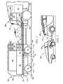
- FIG. 2is a schematic side-view of an exemplary parent vehicle 200 coupled to an exemplary semi-autonomous vehicle 100 via an exemplary electrical coupler 10 .
- the body element 190 for the semi-autonomous wheeled vehicle 100is designed to conform to body contours of the parent vehicle 200 to minimize drag.
- An exemplary target device 275is also depicted on the parent vehicle 200 .
- the controller 180is programmable, thus allowing an operator or a skilled technician to program the controller 180 such that the control system for the semi-autonomous wheeled vehicle 100 conforms to the selected parent vehicle 200 , taking into account features of the parent vehicle 200 and communications protocols associated therewith.
- One feature of the parent vehicle 200 that may be provided by the semi-autonomous wheeled vehicle 100may be rear obstacle detection.
- Control modulemeans any suitable one or various combinations of one or more of Application Specific Integrated Circuit(s) (ASIC), electronic circuit(s), central processing unit(s) (preferably microprocessor(s)) and associated memory and storage (read only, programmable read only, random access, hard drive, etc.) executing one or more software or firmware programs, combinatorial logic circuit(s), input/output circuit(s) and devices, appropriate signal conditioning and buffer circuitry, and other suitable components to provide the described functionality.
- ASICApplication Specific Integrated Circuit
- the control modulehas a set of control algorithms, including resident software program instructions and calibrations stored in memory and executed to provide the desired functions. The algorithms are preferably executed during preset loop cycles.
- Algorithmsare executed, such as by a central processing unit, and are operable to monitor inputs from sensing devices and other networked control modules, and execute control and diagnostic routines to control operation of actuators. Loop cycles may be executed at regular intervals, for example each 3.125, 6.25, 12.5, 25 and 100 milliseconds during ongoing engine and vehicle operation. Alternatively, algorithms may be executed in response to occurrence of an event.
- FIG. 3schematically illustrates an embodiment of the semi-autonomous wheeled vehicle 100 ′.
- the semi-autonomous vehicle 100 ′includes an electric power generation system including an internal combustion engine 310 operatively coupled to an electric generator 320 that generates electric power that is transferred to the high-voltage electric power storage system 125 of the semi-autonomous wheeled vehicle 100 ′ and/or to the on-vehicle high-voltage electrical energy storage system 225 of the parent vehicle 200 .
- the semi-autonomous vehicle 100 ′includes a liquid fuel storage system 315 configured to store and transfer liquid fuel to the internal combustion engine 310 during operation.
- the charge capacity and associated quantity of cells contained in the high-voltage electric power storage system 125may be reduced, with any associated vehicle weight advantage offset by the internal combustion engine 310 and the electric generator 320 . All other functions remain as described with reference to FIG. 1 .
- the internal combustion engine 310may be any suitable configuration of appropriate size and power output to achieve a requisite electric power output. It is appreciated that the internal combustion engine 310 may operate on gasoline, diesel fuel, LPG, natural gas, ethanol, or another suitable fuel.
- FIG. 4schematically illustrates an embodiment of the semi-autonomous vehicle 100 ′′.
- the semi-autonomous vehicle 100 ′′includes an electric power generation system including a fuel cell 410 that generates electric power that is transferred to the high-voltage electric power storage system 125 of the semi-autonomous wheeled vehicle 100 ′′ and/or to the on-vehicle high-voltage electrical energy storage system 225 of the parent vehicle 200 .
- the semi-autonomous vehicle 100 ′′includes a liquid fuel storage system 415 configured to store and transfer liquid fuel to the fuel cell 410 during operation.
- the charge capacity and associated quantity of cells contained in the high-voltage electric power storage system 125may be reduced, with any associated vehicle weight advantage offset by the fuel cell 410 and corresponding effect on cargo space in the stowage and conveyance system 105 . All other functions remain as described.
- the fuel cell 410may be any suitable fuel cell configuration of appropriate size and power output to achieve a requisite electric power output, including, e.g., a polymer exchange membrane fuel cell and a solid-oxide fuel cell. It is appreciated that the fuel cell 410 may operate on hydrocarbon fuel, hydrogen, or another suitable fuel.
Landscapes
- Engineering & Computer Science (AREA)
- Transportation (AREA)
- Mechanical Engineering (AREA)
- Chemical & Material Sciences (AREA)
- Combustion & Propulsion (AREA)
- Automation & Control Theory (AREA)
- Power Engineering (AREA)
- Aviation & Aerospace Engineering (AREA)
- Radar, Positioning & Navigation (AREA)
- Remote Sensing (AREA)
- Physics & Mathematics (AREA)
- General Physics & Mathematics (AREA)
- Electric Propulsion And Braking For Vehicles (AREA)
Abstract
Description
Claims (20)
Priority Applications (1)
| Application Number | Priority Date | Filing Date | Title |
|---|---|---|---|
| US13/016,969US8627908B2 (en) | 2011-01-29 | 2011-01-29 | Semi-autonomous vehicle providing an auxiliary power supply |
Applications Claiming Priority (1)
| Application Number | Priority Date | Filing Date | Title |
|---|---|---|---|
| US13/016,969US8627908B2 (en) | 2011-01-29 | 2011-01-29 | Semi-autonomous vehicle providing an auxiliary power supply |
Publications (2)
| Publication Number | Publication Date |
|---|---|
| US20120193153A1 US20120193153A1 (en) | 2012-08-02 |
| US8627908B2true US8627908B2 (en) | 2014-01-14 |
Family
ID=46576420
Family Applications (1)
| Application Number | Title | Priority Date | Filing Date |
|---|---|---|---|
| US13/016,969Active2032-07-15US8627908B2 (en) | 2011-01-29 | 2011-01-29 | Semi-autonomous vehicle providing an auxiliary power supply |
Country Status (1)
| Country | Link |
|---|---|
| US (1) | US8627908B2 (en) |
Cited By (33)
| Publication number | Priority date | Publication date | Assignee | Title |
|---|---|---|---|---|
| US9857255B2 (en)* | 2014-01-22 | 2018-01-02 | Ford Global Technologies, Llc | Traction-battery vehicle test trailer |
| US9887570B2 (en)* | 2011-05-10 | 2018-02-06 | Stephen G. Johnsen | Mobile variable power system and method |
| US10040370B2 (en)* | 2015-09-19 | 2018-08-07 | Ningbo Wise Digital Technology Co., Ltd | Container comprising a battery, transportation system comprising the same and method thereof |
| US10245972B2 (en)* | 2015-05-01 | 2019-04-02 | Hyliion Inc. | Trailer-based energy capture and management |
| US10309871B2 (en) | 2016-09-22 | 2019-06-04 | Ford Global Technologie, Llc | Trailer for measuring operating characteristics of a vehicle |
| US10333338B2 (en)* | 2017-10-23 | 2019-06-25 | Ford Global Technologies, Llc | Charging method and assembly utilizing a mule vehicle with a storage battery |
| US10384560B2 (en) | 2015-05-01 | 2019-08-20 | Hyliion Inc. | Motor vehicle accessory to increase power supply and reduce fuel requirements |
| US10500975B1 (en) | 2016-09-30 | 2019-12-10 | Hyliion Inc. | Vehicle weight estimation system and related methods |
| US20200077861A1 (en)* | 2018-09-06 | 2020-03-12 | Lg Electronics Inc. | Robot cleaner and a controlling method for the same |
| US10596913B2 (en) | 2015-05-01 | 2020-03-24 | Hyliion Inc. | Trailer-based energy capture and management |
| US10766478B2 (en) | 2017-02-17 | 2020-09-08 | Hyliion Inc. | Tractor unit with on-board regenerative braking energy storage for stopover HVAC operation without engine idle |
| US10821853B2 (en) | 2016-09-30 | 2020-11-03 | Hyliion Inc. | Vehicle energy management system and related methods |
| US10889288B2 (en) | 2017-12-31 | 2021-01-12 | Hyliion Inc. | Electric drive controller adaptation to through-the-road (TTR) coupled primary engine and/or operating conditions |
| US10988193B2 (en) | 2018-02-16 | 2021-04-27 | Deere & Company | Disconnectable work implement drive system |
| US11046302B2 (en) | 2017-12-31 | 2021-06-29 | Hyliion Inc. | On-vehicle characterization of primary engine with communication interface for crowdsourced adaptation of electric drive controllers |
| US11046192B2 (en) | 2017-12-31 | 2021-06-29 | Hyliion Inc. | Electric vehicle energy store with fuel tank form factor and mounting configuration |
| US11094988B2 (en) | 2017-12-31 | 2021-08-17 | Hyliion Inc. | Regenerative electrical power system with state of charge management in view of predicted and-or scheduled stopover auxiliary power requirements |
| US11091133B2 (en) | 2017-12-31 | 2021-08-17 | Hyliion Inc. | Vehicle immobilization mechanism |
| US11186314B2 (en) | 2018-08-22 | 2021-11-30 | Plasan Sasa Ltd. | Articulated vehicle assembly and articulation system for use therein |
| US11269355B2 (en) | 2018-09-06 | 2022-03-08 | Lg Electronics Inc. | Plurality of autonomous mobile robots and controlling method for the same |
| US20220089010A1 (en)* | 2018-08-22 | 2022-03-24 | Hymer Business Development Gmbh | Mobile Home |
| US20220126724A1 (en)* | 2020-10-26 | 2022-04-28 | Ford Global Technologies, Llc | Portable high-voltage vehicle charging system |
| US11345210B2 (en) | 2017-10-09 | 2022-05-31 | Carrier Corporation | High voltage auxiliary power unit for a transportation refrigeration system |
| US11351979B2 (en) | 2017-12-31 | 2022-06-07 | Hyliion Inc. | Supplemental electric drive with primary engine recognition for electric drive controller adaptation |
| US11409308B2 (en) | 2018-09-06 | 2022-08-09 | Lg Electronics Inc. | Robot cleaner and a controlling method for the same |
| EP4088955A1 (en)* | 2021-05-10 | 2022-11-16 | Plasan Sasa Ltd | A controllable electric vehicle and a control system therefor |
| US11581847B2 (en)* | 2020-04-17 | 2023-02-14 | Henry Kamahoahoa FATA | Photovoltaic and electromagnetic powered mobile electric vehicle charging station |
| US20230264766A1 (en)* | 2022-02-23 | 2023-08-24 | Toyota Motor Engineering & Manufacturing North America, Inc. | Modular vehicle power source storage |
| US11945529B2 (en) | 2021-05-10 | 2024-04-02 | Plasan Sasa Ltd. | Dual use trailer vehicle |
| US12024029B2 (en) | 2015-05-01 | 2024-07-02 | Hyliion Inc. | Trailer-based energy capture and management |
| US12024065B1 (en) | 2023-07-06 | 2024-07-02 | Mordechai Teicher | Transportation of electric vehicles |
| US12103512B2 (en)* | 2022-05-04 | 2024-10-01 | Ford Global Technologies, Llc | Energy optimization for integrated powertrain of combined vehicle system having vehicle and electrically powered trailer towed by the vehicle |
| US12109858B1 (en) | 2023-07-06 | 2024-10-08 | Mordechai Teicher | Autonomous vehicle for road and rail |
Families Citing this family (44)
| Publication number | Priority date | Publication date | Assignee | Title |
|---|---|---|---|---|
| US8602143B2 (en)* | 2011-03-17 | 2013-12-10 | GM Global Technology Operations LLC | Electric vehicle with range-extending engine and climate control compressor |
| TWI421177B (en)* | 2011-03-18 | 2014-01-01 | Ind Tech Res Inst | Methods and systems of saving energy control |
| JP6565009B2 (en)* | 2014-07-18 | 2019-08-28 | 株式会社日本総合研究所 | Collective transfer device |
| DE102014012090A1 (en)* | 2014-08-13 | 2016-02-18 | Man Truck & Bus Ag | Hybrid vehicle with an external electrical interface |
| DE102015205811A1 (en)* | 2015-03-31 | 2016-10-06 | Bvb Innovate Gmbh | Use of Range Extender Vehicle and Range Extender Vehicle |
| CN105235548A (en)* | 2015-10-23 | 2016-01-13 | 国网山东海阳市供电公司 | Electric driving system of electric automobile |
| US10000124B2 (en) | 2015-11-04 | 2018-06-19 | Zoox, Inc. | Independent steering, power, torque control and transfer in vehicles |
| US9802661B1 (en) | 2015-11-04 | 2017-10-31 | Zoox, Inc. | Quadrant configuration of robotic vehicles |
| US10248119B2 (en)* | 2015-11-04 | 2019-04-02 | Zoox, Inc. | Interactive autonomous vehicle command controller |
| DE102015225789A1 (en)* | 2015-12-17 | 2017-06-22 | Volkswagen Aktiengesellschaft | Mobile energy storage and method for providing energy to a consumer |
| EP3246193A1 (en)* | 2016-05-20 | 2017-11-22 | railCare AG | Energy supply assembly |
| US10005500B2 (en)* | 2016-06-10 | 2018-06-26 | CNH Idustrial America LLC | Operator station for an autonomous work vehicle |
| US10011181B2 (en) | 2016-09-27 | 2018-07-03 | Ford Global Technologies, Llc | Vehicle-to-vehicle charging system |
| JP6798250B2 (en)* | 2016-10-26 | 2020-12-09 | 村田機械株式会社 | Traveling vehicle |
| DE102016221694A1 (en)* | 2016-11-04 | 2018-05-09 | Audi Ag | Towing assistance for a motor vehicle |
| US10338594B2 (en)* | 2017-03-13 | 2019-07-02 | Nio Usa, Inc. | Navigation of autonomous vehicles to enhance safety under one or more fault conditions |
| US20180312051A1 (en)* | 2017-04-27 | 2018-11-01 | Cool Technologies, Inc. | Integrated electrical power generation methods and systems |
| US10423162B2 (en) | 2017-05-08 | 2019-09-24 | Nio Usa, Inc. | Autonomous vehicle logic to identify permissioned parking relative to multiple classes of restricted parking |
| US10737737B2 (en)* | 2017-05-31 | 2020-08-11 | Zoox, Inc. | Vehicle with interchangeable drive modules |
| US10710633B2 (en) | 2017-07-14 | 2020-07-14 | Nio Usa, Inc. | Control of complex parking maneuvers and autonomous fuel replenishment of driverless vehicles |
| US10369974B2 (en) | 2017-07-14 | 2019-08-06 | Nio Usa, Inc. | Control and coordination of driverless fuel replenishment for autonomous vehicles |
| DE102017218854A1 (en) | 2017-10-23 | 2019-04-25 | Audi Ag | Method for operating a motor vehicle and motor vehicle |
| US20190129429A1 (en)* | 2017-10-26 | 2019-05-02 | Uber Technologies, Inc. | Systems and Methods for Determining Tractor-Trailer Angles and Distances |
| DE102017219730A1 (en)* | 2017-11-07 | 2019-05-09 | Ford Global Technologies, Llc | Mobile energy storage |
| FR3075119B1 (en)* | 2017-12-14 | 2022-03-04 | Valeo Systemes De Controle Moteur | METHOD FOR MODIFYING THE STATE OF AN ELECTRIC ENERGY STORAGE UNIT OF A VEHICLE |
| US11022971B2 (en) | 2018-01-16 | 2021-06-01 | Nio Usa, Inc. | Event data recordation to identify and resolve anomalies associated with control of driverless vehicles |
| AT521061A1 (en)* | 2018-03-21 | 2019-10-15 | Mair Christian | Coupling external power generator for electric vehicles |
| DE102018206582A1 (en)* | 2018-04-27 | 2019-10-31 | Audi Ag | Charging method for an energy storage of an electrically driven motor vehicle, charging system for charging an energy storage of an electrically driven motor vehicle and motor vehicle, which can cooperate with such a charging system |
| SE542628C2 (en)* | 2018-06-29 | 2020-06-23 | Scania Cv Ab | A METHOD FOR CONTROLLING PHYSICALLY CONNECTING A FIRST AND A SECOND MODULE TO ASSEMBLE A VEHICLE, A CONTROL DEVICE, A VEHICLE, A SYSTEM, A COMPUTER PROGRAM AND A COMPUTER-READABLE MEDIUM |
| EE01483U1 (en)* | 2019-04-17 | 2020-02-17 | Andrei Raag | Active trailer with electric drive |
| DE102019211494A1 (en)* | 2019-08-01 | 2021-02-04 | Audi Ag | System for supplying a motor vehicle and motor vehicle having an energy storage unit |
| US10926818B1 (en)* | 2019-08-22 | 2021-02-23 | Ioan Sasu | Pooling vehicle and trailer system |
| EE01512U1 (en)* | 2019-09-05 | 2020-10-15 | GoTrack OÜ | Onboard safety equipment |
| JP7142073B2 (en)* | 2020-11-05 | 2022-09-26 | 本田技研工業株式会社 | housing |
| JP2022074967A (en)* | 2020-11-05 | 2022-05-18 | 本田技研工業株式会社 | How to control the fuel cell system |
| US11890926B2 (en)* | 2020-11-10 | 2024-02-06 | Freedom Fuels USA, Inc. | Auxiliary fueling system for trailer mounted engines |
| EP4011656B1 (en)* | 2020-12-10 | 2023-09-13 | Volvo Truck Corporation | A control system and method for a trailer or dolly |
| US11928966B2 (en) | 2021-01-13 | 2024-03-12 | Divergent Technologies, Inc. | Virtual railroad |
| WO2022211819A1 (en)* | 2021-04-02 | 2022-10-06 | Volvo Truck Corporation | Auxiliary range extension for battery electric vehicle |
| JP7453185B2 (en)* | 2021-07-13 | 2024-03-19 | 矢崎総業株式会社 | Delivery systems, servers and programs for delivery systems |
| GB2613556A (en)* | 2021-12-03 | 2023-06-14 | Caterpillar Inc | Charging management for electric work vehicles |
| US12221109B2 (en)* | 2022-10-10 | 2025-02-11 | GM Global Technology Operations LLC | Road congestion-aware automatic lane change activation before lane termination |
| WO2024239057A1 (en)* | 2023-05-21 | 2024-11-28 | CI Corporation Pty Ltd | Automated electric trailer with unsprung wheel hub motors |
| CN120096351B (en)* | 2025-05-09 | 2025-09-12 | 质子汽车科技有限公司 | Primary and secondary vehicle energy sharing system, control method and primary and secondary vehicle system |
Citations (18)
| Publication number | Priority date | Publication date | Assignee | Title |
|---|---|---|---|---|
| US5810105A (en) | 1995-03-15 | 1998-09-22 | Technologietransfer-Anstalt Tetra | Ultrasonic tracking control for an automotive vehicle |
| US5921708A (en) | 1996-10-01 | 1999-07-13 | Joseph Voegele Ag | Pavement-vehicle convoy |
| US6301530B1 (en) | 1999-06-23 | 2001-10-09 | Honda Giken Kobgyo Kabushiki Kaisha | Automatic following travel system |
| US6313758B1 (en) | 1999-05-31 | 2001-11-06 | Honda Giken Kogyo Kabushiki Kaisha | Automatic following travel system |
| WO2002023296A1 (en) | 2000-09-12 | 2002-03-21 | Ainsworth, Inc. | Method of and apparatus for guidance of automated vehicles |
| US6640164B1 (en) | 2001-08-28 | 2003-10-28 | Itt Manufacturing Enterprises, Inc. | Methods and systems for remote control of self-propelled vehicles |
| US20050162106A1 (en) | 2004-01-22 | 2005-07-28 | Wavecrest Laboratories Llc | Portable range extender operable in automatic and manual modes |
| US7277784B2 (en) | 2002-05-31 | 2007-10-02 | Deere & Company | Combination of a self-moving harvesting machine and a transport vehicle |
| US20070233337A1 (en) | 2005-09-14 | 2007-10-04 | Plishner Paul J | Semi-autonomous guidance system for a vehicle |
| US20080059007A1 (en) | 2006-06-09 | 2008-03-06 | Whittaker William L | System and method for autonomously convoying vehicles |
| US7593811B2 (en) | 2005-03-31 | 2009-09-22 | Deere & Company | Method and system for following a lead vehicle |
| JP2010015194A (en) | 2008-06-30 | 2010-01-21 | Ihi Corp | Autonomous moving robot device and control method for autonomous moving robot device |
| US20100044998A1 (en) | 2006-05-17 | 2010-02-25 | Eurolum | Wheeled vehicle, hitching method, unhitching method, method for managing said vehicles and resulting train of vehicles |
| US20100065344A1 (en)* | 2008-09-12 | 2010-03-18 | Collings Iii John K | Self Propelled Electric Vehicle Recharging Trailer |
| US20120168234A1 (en)* | 2009-07-07 | 2012-07-05 | Hellholm Bjoerm | Articulated tracked vehicle |
| US20120193154A1 (en)* | 2011-01-29 | 2012-08-02 | GM Global Technology Operations LLC | Semi-autonomous vehicle providing cargo space |
| US20120245796A1 (en)* | 2011-03-25 | 2012-09-27 | Jinghong Yu | System and method for controlling a trailer connected to a vehicle |
| US20130006451A1 (en)* | 2011-07-01 | 2013-01-03 | Cooper Jared | System and method for vehicle control |
- 2011
- 2011-01-29USUS13/016,969patent/US8627908B2/enactiveActive
Patent Citations (18)
| Publication number | Priority date | Publication date | Assignee | Title |
|---|---|---|---|---|
| US5810105A (en) | 1995-03-15 | 1998-09-22 | Technologietransfer-Anstalt Tetra | Ultrasonic tracking control for an automotive vehicle |
| US5921708A (en) | 1996-10-01 | 1999-07-13 | Joseph Voegele Ag | Pavement-vehicle convoy |
| US6313758B1 (en) | 1999-05-31 | 2001-11-06 | Honda Giken Kogyo Kabushiki Kaisha | Automatic following travel system |
| US6301530B1 (en) | 1999-06-23 | 2001-10-09 | Honda Giken Kobgyo Kabushiki Kaisha | Automatic following travel system |
| WO2002023296A1 (en) | 2000-09-12 | 2002-03-21 | Ainsworth, Inc. | Method of and apparatus for guidance of automated vehicles |
| US6640164B1 (en) | 2001-08-28 | 2003-10-28 | Itt Manufacturing Enterprises, Inc. | Methods and systems for remote control of self-propelled vehicles |
| US7277784B2 (en) | 2002-05-31 | 2007-10-02 | Deere & Company | Combination of a self-moving harvesting machine and a transport vehicle |
| US20050162106A1 (en) | 2004-01-22 | 2005-07-28 | Wavecrest Laboratories Llc | Portable range extender operable in automatic and manual modes |
| US7593811B2 (en) | 2005-03-31 | 2009-09-22 | Deere & Company | Method and system for following a lead vehicle |
| US20070233337A1 (en) | 2005-09-14 | 2007-10-04 | Plishner Paul J | Semi-autonomous guidance system for a vehicle |
| US20100044998A1 (en) | 2006-05-17 | 2010-02-25 | Eurolum | Wheeled vehicle, hitching method, unhitching method, method for managing said vehicles and resulting train of vehicles |
| US20080059007A1 (en) | 2006-06-09 | 2008-03-06 | Whittaker William L | System and method for autonomously convoying vehicles |
| JP2010015194A (en) | 2008-06-30 | 2010-01-21 | Ihi Corp | Autonomous moving robot device and control method for autonomous moving robot device |
| US20100065344A1 (en)* | 2008-09-12 | 2010-03-18 | Collings Iii John K | Self Propelled Electric Vehicle Recharging Trailer |
| US20120168234A1 (en)* | 2009-07-07 | 2012-07-05 | Hellholm Bjoerm | Articulated tracked vehicle |
| US20120193154A1 (en)* | 2011-01-29 | 2012-08-02 | GM Global Technology Operations LLC | Semi-autonomous vehicle providing cargo space |
| US20120245796A1 (en)* | 2011-03-25 | 2012-09-27 | Jinghong Yu | System and method for controlling a trailer connected to a vehicle |
| US20130006451A1 (en)* | 2011-07-01 | 2013-01-03 | Cooper Jared | System and method for vehicle control |
Non-Patent Citations (1)
| Title |
|---|
| U.S. Appl. No. 13/016,975, filed Jan. 29, 2011, Wellborn, et al. |
Cited By (63)
| Publication number | Priority date | Publication date | Assignee | Title |
|---|---|---|---|---|
| US10737583B2 (en) | 2011-05-10 | 2020-08-11 | Stephen G. Johnsen | Mobile variable power system and method |
| US9887570B2 (en)* | 2011-05-10 | 2018-02-06 | Stephen G. Johnsen | Mobile variable power system and method |
| US9857255B2 (en)* | 2014-01-22 | 2018-01-02 | Ford Global Technologies, Llc | Traction-battery vehicle test trailer |
| US10384560B2 (en) | 2015-05-01 | 2019-08-20 | Hyliion Inc. | Motor vehicle accessory to increase power supply and reduce fuel requirements |
| US12024029B2 (en) | 2015-05-01 | 2024-07-02 | Hyliion Inc. | Trailer-based energy capture and management |
| US11833905B2 (en) | 2015-05-01 | 2023-12-05 | Hyliion Inc. | Trailer-based energy capture and management |
| US10967742B2 (en) | 2015-05-01 | 2021-04-06 | Hyliion Inc. | Motor vehicle accessory to increase power supply and reduce fuel requirements |
| US10549647B2 (en) | 2015-05-01 | 2020-02-04 | Hyliion Inc. | Motor vehicle accessory to increase power supply and reduce fuel requirements |
| US12319150B2 (en) | 2015-05-01 | 2025-06-03 | Hyliion Inc. | Trailer-based energy capture and management |
| US10596913B2 (en) | 2015-05-01 | 2020-03-24 | Hyliion Inc. | Trailer-based energy capture and management |
| US10654369B2 (en) | 2015-05-01 | 2020-05-19 | Hyliion Inc. | Motor vehicle accessory to increase power supply and reduce fuel requirements |
| US10245972B2 (en)* | 2015-05-01 | 2019-04-02 | Hyliion Inc. | Trailer-based energy capture and management |
| US10960773B2 (en) | 2015-05-01 | 2021-03-30 | Hyliion Inc. | Motor vehicle accessory to increase power supply and reduce fuel requirements |
| US10040370B2 (en)* | 2015-09-19 | 2018-08-07 | Ningbo Wise Digital Technology Co., Ltd | Container comprising a battery, transportation system comprising the same and method thereof |
| US10309871B2 (en) | 2016-09-22 | 2019-06-04 | Ford Global Technologie, Llc | Trailer for measuring operating characteristics of a vehicle |
| US10821853B2 (en) | 2016-09-30 | 2020-11-03 | Hyliion Inc. | Vehicle energy management system and related methods |
| US10906406B1 (en) | 2016-09-30 | 2021-02-02 | Hyliion Inc. | Vehicle weight estimation system and related methods |
| US10500975B1 (en) | 2016-09-30 | 2019-12-10 | Hyliion Inc. | Vehicle weight estimation system and related methods |
| US11766951B2 (en) | 2016-09-30 | 2023-09-26 | Hyliion Inc. | Vehicle energy management system and related methods |
| US11479144B2 (en) | 2016-09-30 | 2022-10-25 | Hyliion Inc. | Vehicle energy management system and related methods |
| US10766478B2 (en) | 2017-02-17 | 2020-09-08 | Hyliion Inc. | Tractor unit with on-board regenerative braking energy storage for stopover HVAC operation without engine idle |
| US11904697B2 (en) | 2017-02-17 | 2024-02-20 | Hyliion Inc. | Tractor unit with on-board regenerative braking energy storage for stopover HVAC operation without engine idle |
| US11305634B2 (en) | 2017-02-17 | 2022-04-19 | Hyliion Inc. | Tractor unit with on-board regenerative braking energy storage for stopover HVAC operation without engine idle |
| US11370292B2 (en) | 2017-02-17 | 2022-06-28 | Hyliion Inc. | Tractor unit with on-board regenerative braking energy storage for stopover HVAC operation without engine idle |
| US11305633B2 (en) | 2017-02-17 | 2022-04-19 | Hyliion Inc. | Tractor unit with on-board regenerative braking energy storage for stopover HVAC operation without engine idle |
| US11345210B2 (en) | 2017-10-09 | 2022-05-31 | Carrier Corporation | High voltage auxiliary power unit for a transportation refrigeration system |
| US10333338B2 (en)* | 2017-10-23 | 2019-06-25 | Ford Global Technologies, Llc | Charging method and assembly utilizing a mule vehicle with a storage battery |
| US11351979B2 (en) | 2017-12-31 | 2022-06-07 | Hyliion Inc. | Supplemental electric drive with primary engine recognition for electric drive controller adaptation |
| US11046192B2 (en) | 2017-12-31 | 2021-06-29 | Hyliion Inc. | Electric vehicle energy store with fuel tank form factor and mounting configuration |
| US10889288B2 (en) | 2017-12-31 | 2021-01-12 | Hyliion Inc. | Electric drive controller adaptation to through-the-road (TTR) coupled primary engine and/or operating conditions |
| US11876236B2 (en) | 2017-12-31 | 2024-01-16 | Hyliion Inc. | Regenerative electrical power system with state of charge management in view of predicted and-or scheduled stopover auxiliary power requirements |
| US11046302B2 (en) | 2017-12-31 | 2021-06-29 | Hyliion Inc. | On-vehicle characterization of primary engine with communication interface for crowdsourced adaptation of electric drive controllers |
| US11091133B2 (en) | 2017-12-31 | 2021-08-17 | Hyliion Inc. | Vehicle immobilization mechanism |
| US12136738B2 (en) | 2017-12-31 | 2024-11-05 | Hyliion Inc. | Regenerative electrical power system with state of charge management in view of predicted and/or scheduled stopover auxiliary power requirements |
| US11932232B2 (en) | 2017-12-31 | 2024-03-19 | Hyliion Inc. | Supplemental electric drive with primary engine recognition for electric drive controller adaptation |
| US11094988B2 (en) | 2017-12-31 | 2021-08-17 | Hyliion Inc. | Regenerative electrical power system with state of charge management in view of predicted and-or scheduled stopover auxiliary power requirements |
| US11527799B2 (en) | 2017-12-31 | 2022-12-13 | Hyliion Inc. | Regenerative electrical power system with state of charge management in view of predicted and-or scheduled stopover auxiliary power requirements |
| US12286092B2 (en) | 2017-12-31 | 2025-04-29 | Hyliion Inc. | Supplemental electric drive with primary engine recognition for electric drive controller adaptation |
| US10988193B2 (en) | 2018-02-16 | 2021-04-27 | Deere & Company | Disconnectable work implement drive system |
| US20220089010A1 (en)* | 2018-08-22 | 2022-03-24 | Hymer Business Development Gmbh | Mobile Home |
| US12240309B2 (en)* | 2018-08-22 | 2025-03-04 | Erwin Hymer Group Se | Mobile home |
| US11186314B2 (en) | 2018-08-22 | 2021-11-30 | Plasan Sasa Ltd. | Articulated vehicle assembly and articulation system for use therein |
| US20200077861A1 (en)* | 2018-09-06 | 2020-03-12 | Lg Electronics Inc. | Robot cleaner and a controlling method for the same |
| US11432697B2 (en)* | 2018-09-06 | 2022-09-06 | Lg Electronics Inc. | Robot cleaner and a controlling method for the same |
| US11409308B2 (en) | 2018-09-06 | 2022-08-09 | Lg Electronics Inc. | Robot cleaner and a controlling method for the same |
| US11269355B2 (en) | 2018-09-06 | 2022-03-08 | Lg Electronics Inc. | Plurality of autonomous mobile robots and controlling method for the same |
| US11906979B2 (en) | 2018-09-06 | 2024-02-20 | Lg Electronics Inc. | Plurality of autonomous mobile robots and controlling method for the same |
| US11581847B2 (en)* | 2020-04-17 | 2023-02-14 | Henry Kamahoahoa FATA | Photovoltaic and electromagnetic powered mobile electric vehicle charging station |
| US11745614B2 (en)* | 2020-10-26 | 2023-09-05 | Ford Global Technologies, Llc | Portable high-voltage vehicle charging system |
| US20220126724A1 (en)* | 2020-10-26 | 2022-04-28 | Ford Global Technologies, Llc | Portable high-voltage vehicle charging system |
| EP4088955A1 (en)* | 2021-05-10 | 2022-11-16 | Plasan Sasa Ltd | A controllable electric vehicle and a control system therefor |
| US11945529B2 (en) | 2021-05-10 | 2024-04-02 | Plasan Sasa Ltd. | Dual use trailer vehicle |
| IL283080B2 (en)* | 2021-05-10 | 2024-03-01 | Plasan Sasa Ltd | A Controllable Electric Vehicle and a Control System therefor |
| IL283080B1 (en)* | 2021-05-10 | 2023-11-01 | Plasan Sasa Ltd | A Controllable Electric Vehicle and a Control System therefor |
| IL283080A (en)* | 2021-05-10 | 2022-12-01 | Plasan Sasa Ltd | A controllable electric vehicle and a control system for it |
| US20220371576A1 (en)* | 2021-05-10 | 2022-11-24 | Plasan Sasa Ltd. | Controllable electric vehicle and a control system therefor |
| US12371115B2 (en) | 2021-05-10 | 2025-07-29 | Plasan Sasa Ltd. | Dual use trailer vehicle |
| US12403892B2 (en)* | 2021-05-10 | 2025-09-02 | Plasan Sasa Ltd. | Controllable electric vehicle and a control system therefor |
| US12227242B2 (en)* | 2022-02-23 | 2025-02-18 | Toyota Motor Engineering & Manufacturing North America, Inc. | Modular vehicle power source storage |
| US20230264766A1 (en)* | 2022-02-23 | 2023-08-24 | Toyota Motor Engineering & Manufacturing North America, Inc. | Modular vehicle power source storage |
| US12103512B2 (en)* | 2022-05-04 | 2024-10-01 | Ford Global Technologies, Llc | Energy optimization for integrated powertrain of combined vehicle system having vehicle and electrically powered trailer towed by the vehicle |
| US12024065B1 (en) | 2023-07-06 | 2024-07-02 | Mordechai Teicher | Transportation of electric vehicles |
| US12109858B1 (en) | 2023-07-06 | 2024-10-08 | Mordechai Teicher | Autonomous vehicle for road and rail |
Also Published As
| Publication number | Publication date |
|---|---|
| US20120193153A1 (en) | 2012-08-02 |
Similar Documents
| Publication | Publication Date | Title |
|---|---|---|
| US8627908B2 (en) | Semi-autonomous vehicle providing an auxiliary power supply | |
| US8496078B2 (en) | Semi-autonomous vehicle providing cargo space | |
| US12257922B2 (en) | Methods and apparatus for an active convertor dolly | |
| US12296900B2 (en) | Anti-jackknifing control apparatus and method for active converter dolly | |
| US11203350B2 (en) | Vehicle control system | |
| US11420695B2 (en) | Semi-autonomous trailer hauler | |
| US11485330B1 (en) | Force transducer for a multifunction trailer controller | |
| US12347245B2 (en) | Vehicle management system and vehicle inspection method | |
| WO2019053021A1 (en) | System and method for a trailer towable by a vehicle | |
| WO2024025966A2 (en) | Combination vehicle system and/or method | |
| US11834059B2 (en) | Locating smart shoe relative to pedal | |
| US20250050943A1 (en) | System and method to prevent lateral control by limiting turning by a steering wheel | |
| US11577566B2 (en) | Combinable and detachable vehicle and method for controlling the same | |
| JP7568869B2 (en) | Driving assistance device and recording medium having computer program recorded thereon | |
| CN116767259A (en) | Driving support device, vehicle, and driving support method | |
| US12116062B2 (en) | System and method for providing a center indicator for a temporarily decoupled steering wheel | |
| CN113049846A (en) | System and method for measuring trailer wheel speed | |
| US12172673B2 (en) | System and method for providing friction circle feedback for vehicle safety | |
| US20240399890A1 (en) | Multifunction controller for an electric trailer | |
| CN120756484A (en) | Vehicle control method and device, electronic equipment, storage medium and vehicle |
Legal Events
| Date | Code | Title | Description |
|---|---|---|---|
| AS | Assignment | Owner name:GM GLOBAL TECHNOLOGY OPERATIONS LLC, MICHIGAN Free format text:ASSIGNMENT OF ASSIGNORS INTEREST;ASSIGNORS:WELLBORN, CARL W.;DECALUWE, MARY ELLEN;RAINBOLT, JIM K.;AND OTHERS;SIGNING DATES FROM 20110118 TO 20110128;REEL/FRAME:025718/0069 | |
| AS | Assignment | Owner name:WILMINGTON TRUST COMPANY, DELAWARE Free format text:SECURITY AGREEMENT;ASSIGNOR:GM GLOBAL TECHNOLOGY OPERATIONS LLC;REEL/FRAME:028466/0870 Effective date:20101027 | |
| FEPP | Fee payment procedure | Free format text:PAYOR NUMBER ASSIGNED (ORIGINAL EVENT CODE: ASPN); ENTITY STATUS OF PATENT OWNER: LARGE ENTITY | |
| STCF | Information on status: patent grant | Free format text:PATENTED CASE | |
| AS | Assignment | Owner name:GM GLOBAL TECHNOLOGY OPERATIONS LLC, MICHIGAN Free format text:RELEASE BY SECURED PARTY;ASSIGNOR:WILMINGTON TRUST COMPANY;REEL/FRAME:034287/0159 Effective date:20141017 | |
| FPAY | Fee payment | Year of fee payment:4 | |
| MAFP | Maintenance fee payment | Free format text:PAYMENT OF MAINTENANCE FEE, 8TH YEAR, LARGE ENTITY (ORIGINAL EVENT CODE: M1552); ENTITY STATUS OF PATENT OWNER: LARGE ENTITY Year of fee payment:8 | |
| MAFP | Maintenance fee payment | Free format text:PAYMENT OF MAINTENANCE FEE, 12TH YEAR, LARGE ENTITY (ORIGINAL EVENT CODE: M1553); ENTITY STATUS OF PATENT OWNER: LARGE ENTITY Year of fee payment:12 |