US8624452B2 - Electric machine module cooling system and method - Google Patents
Electric machine module cooling system and methodDownload PDFInfo
- Publication number
- US8624452B2 US8624452B2US13/449,550US201213449550AUS8624452B2US 8624452 B2US8624452 B2US 8624452B2US 201213449550 AUS201213449550 AUS 201213449550AUS 8624452 B2US8624452 B2US 8624452B2
- Authority
- US
- United States
- Prior art keywords
- electric machine
- coolant
- machine module
- rotor hub
- stator
- Prior art date
- Legal status (The legal status is an assumption and is not a legal conclusion. Google has not performed a legal analysis and makes no representation as to the accuracy of the status listed.)
- Active, expires
Links
Images


Classifications
- H—ELECTRICITY
- H02—GENERATION; CONVERSION OR DISTRIBUTION OF ELECTRIC POWER
- H02K—DYNAMO-ELECTRIC MACHINES
- H02K5/00—Casings; Enclosures; Supports
- H02K5/04—Casings or enclosures characterised by the shape, form or construction thereof
- H02K5/20—Casings or enclosures characterised by the shape, form or construction thereof with channels or ducts for flow of cooling medium
- H02K5/203—Casings or enclosures characterised by the shape, form or construction thereof with channels or ducts for flow of cooling medium specially adapted for liquids, e.g. cooling jackets
- Y—GENERAL TAGGING OF NEW TECHNOLOGICAL DEVELOPMENTS; GENERAL TAGGING OF CROSS-SECTIONAL TECHNOLOGIES SPANNING OVER SEVERAL SECTIONS OF THE IPC; TECHNICAL SUBJECTS COVERED BY FORMER USPC CROSS-REFERENCE ART COLLECTIONS [XRACs] AND DIGESTS
- Y10—TECHNICAL SUBJECTS COVERED BY FORMER USPC
- Y10T—TECHNICAL SUBJECTS COVERED BY FORMER US CLASSIFICATION
- Y10T29/00—Metal working
- Y10T29/49—Method of mechanical manufacture
- Y10T29/49002—Electrical device making
- Y10T29/49009—Dynamoelectric machine
Definitions
- Some conventional electric machinesinclude a stator assembly disposed around a rotor assembly.
- Some stator assembliesinclude a plurality of conductors positioned within a stator core. During operation of some electric machines, a current flows through the at least some of the conductors. Moreover, during operation of some electric machines, heat energy can be generated by both the stator assembly and the rotor assembly, as well as some other components of the electric machine. The increase in heat energy produced by some elements of the electric machine can lead to inefficient machine operations.
- an electric machine moduleincluding a housing.
- the housingcan include an inner surface that can define at least a portion of a machine cavity.
- an electric machinecan be at least partially positioned within the machine cavity and can include a stator assembly.
- the stator assemblycan include an outer diameter, a stator core, and a stator winding.
- the stator corecan include at least two extended members that can radially extend from axial ends of the stator core.
- an annular membercan be coupled to the extended members to define at least a portion of a coolant jacket.
- the coolant jacketcan be further defined by the outer diameter of the stator assembly and the extended members.
- the electric machinecan be positioned within the housing so that the annular member is immediately adjacent to the inner surface.
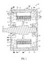
- FIG. 1is a cross-sectional view of an electric machine module according to one embodiment of the invention.
- FIG. 2is a cross-sectional view of an electric machine module according to one embodiment of the invention.
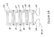
- FIG. 3is a perspective view of a stator assembly according to one embodiment of the invention.
- FIG. 4is front view of a stator lamination according to one embodiment of the invention.
- FIG. 5is a perspective view of a conductor according to one embodiment of the invention.
- FIGS. 6A and 6Bare cross-sectional views of a slot according to some embodiments of the invention.
- FIG. 7is a cross-sectional view of a rotor assembly according to one embodiment of the invention.
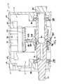
- FIG. 8Ais a cross-sectional view of an electric machine module according to one embodiment of the invention.
- FIG. 8Bis a cross-sectional view of a portion of an electric machine according to one embodiment of the invention.
- FIGS. 1 and 2illustrate an electric machine module 10 according to one embodiment of the invention.
- the module 10can include a housing 12 comprising a sleeve member 14 , a first end cap 16 , and a second end cap 18 .
- An electric machine 20can be housed within a machine cavity 22 at least partially defined by the sleeve member 14 and the end caps 16 , 18 .
- the sleeve member 14 and the end caps 16 , 18can be coupled via conventional fasteners (not shown), or another suitable coupling method, to enclose at least a portion of the electric machine 20 within the machine cavity 22 .
- the housing 12can comprise a substantially cylindrical canister 15 coupled to an end cap 17 , as shown in FIG. 2 .
- the housing 12can comprise materials that can generally include thermally conductive properties, such as, but not limited to aluminum or other metals and materials capable of generally withstanding operating temperatures of the electric machine 20 .
- the housing 12can be fabricated using different methods including casting, molding, extruding, and other similar manufacturing methods.
- the electric machine 20can include a rotor assembly 24 , a stator assembly 26 , and bearings 28 , and can be disposed about a shaft 30 .
- the stator assembly 26can substantially circumscribe at least a portion of the rotor assembly 24 .
- the rotor assembly 24can also include a rotor hub 32 or can have a “hub-less” design (not shown).
- the electric machine 20can be operatively coupled to the housing 12 .
- the electric machine 20can be fit within the housing 12 .
- the electric machine 20can be fit within the housing 12 using an interference fit, a shrink fit, other similar friction-based fits that can at least partially operatively couple the machine 20 and the housing 12 .
- portions of the stator assembly 26 or other portions of the electric machine 20can be shrunk fit into the housing 12 .
- the fitcan at least partially secure the stator assembly 26 , and as a result, the electric machine 20 , in axial, radial and circumferential directions.
- the fit between the stator assembly 26 and the housing 12can at least partially serve to transfer torque from the stator assembly 26 to the housing 12 . In some embodiments, the fit can result in a generally greater amount of torque retained by the module 10 .
- the electric machine 20can be, without limitation, an electric motor, such as a hybrid electric motor, an electric generator, or a vehicle alternator.
- the electric machine 20can be a High Voltage Hairpin (HVH) electric motor, an interior permanent magnet electric motor, or an induction motor for hybrid vehicle applications.
- HVHHigh Voltage Hairpin
- the stator assembly 26can comprise a stator core 34 and a stator winding 36 at least partially disposed within a portion of the stator core 34 .
- the stator core 34can comprise a plurality of laminations 38 .
- the laminations 38can comprise a magnetic material such as iron-cobalt, silicon steel, a composite, or another suitable material. At least a portion of the laminations 38 can be coupled together using a bonding process (e.g., where a bonding agent is used to anneal the laminations 38 together so that a substantially or completely liquid-tight seal is formed) or another suitable coupling process.
- some bonding agents that are capable of being used in the bonding processcan comprise, loctite, titanium oxide, aluminum oxide, or any other suitable compound.
- the laminations 38can comprise a plurality of substantially radially-oriented teeth 40 .
- the teeth 40can substantially align to define a plurality of slots 42 that are configured and arranged to support at least a portion of the stator winding 36 .
- the laminations 38can include sixty teeth 40 , and, as a result, the stator core 34 can include sixty slots 42 .
- the laminations 38can include more or fewer teeth 40 , and, accordingly, the stator core 34 can include more or fewer slots 42 .
- the slots 42can comprise a skewed and/or twisted configuration, which can lead to enhanced motor operations by reducing and/or eliminating torque ripple.
- the stator core 34can comprise an inner perimeter 41 and an outer perimeter 43 .
- the stator assembly 26including the stator core 34 can comprise a substantially cylindrical configuration so that the inner and outer perimeters 41 , 43 can comprise inner and outer diameters, respectively.
- the stator core 34can comprise other configurations (e.g., square, rectangular, elliptical, regular or irregular polygonal, etc.), and, as a result, the inner and outer perimeters 41 , 43 can comprise other dimensions.
- the stator winding 36can comprise a plurality of conductors 44 .
- the conductors 44can comprise a substantially segmented configuration (e.g., a hairpin configuration), as shown in FIGS. 3 and 5 .
- at least a portion of the conductors 44can include a turn portion 46 and at least two leg portions 48 .
- the turn portion 46can be disposed between the two leg portions 48 to substantially connect the two leg portions 48 .
- the leg portions 48can be substantially parallel.
- the turn portion 46can comprise a substantially “u-shaped” configuration, although, in some embodiments, the turn portion 46 can comprise a v-shape, a wave shape, a curved shape, and other shapes. Additionally, in some embodiments, as shown in FIG. 5 , at least a portion of the conductors 44 can comprise a substantially rectangular cross section. In some embodiments, at least a portion of the conductors 44 can comprise other cross-sectional shapes, such as substantially circular, square, hemispherical, regular or irregular polygonal, etc. In some embodiments, the conductors 44 can comprise other configurations (e.g., substantially non-segmented configuration). For example, in some embodiments, the stator winding 36 can comprise a conventional continuous wind and/or a conventional distributed wind configuration.
- the stator assembly 26can comprise one or more insulating members, apparatuses, and/or other structures configured and arranged to provide mechanical, electrical, and physical insulation to some portions of the stator assembly 26 .
- at least a portion of some of the conductors 44can comprise a first insulation 50 .
- the first insulation 50can comprise a resinous material such as an epoxy and/or an enamel that can be reversibly or irreversibly coupled to at least a portion of the conductors 44 .
- the first insulation 50can function, at least in part, to substantially prevent short circuits and/or grounding events between adjacent conductors 44 and/or conductors 44 and the stator core 34 .
- the first insulation 50can comprise a shrunk-fit structure coupled to at least some of the conductors 44 so that the first insulation 50 is retained when the conductors 44 are disposed within the stator core 28 .
- the first insulation 50can be wrapped, wound, or otherwise disposed on, or coupled to, the conductors (e.g., via an adhesive).
- at least a portion of the conductors 44can substantially function without some or all of the first insulation 50 .
- the conductors 44can be generally fabricated from a substantially linear conductor 44 that can be configured and arranged to a shape substantially similar to the conductor in FIG. 5 .
- a machine(not shown) can apply a force (e.g., bend, push, pull, other otherwise actuate) to at least a portion of a conductor 44 to substantially form the turn portion 46 and the two leg portions 48 of a single conductor 44 .
- at least a portion of the conductors 44can be configured into a desired shape after coupling of the first insulation 50 to the conductors 44 .
- At least a portion of the conductors 44can be configured (e.g., bent, pushed, pulled, etc.) into a desired shape (e.g., a hairpin) and then the first insulation 50 can be coupled to the conductors 44 .
- the stator assembly 26can comprise a second layer of insulation.
- the second layer of insulationcan comprise at least one slot member 52 .
- the stator assembly 26can comprise at least one slot member 52 disposed in one or more of the slots 42 .
- one or more slot members 52can be disposed in some or all of the slots 42 .
- each slot 42can comprise at least one slot member 52 .
- at least a portion of the slot members 52can comprise a substantially cylindrical shape.
- the slot members 52can comprise other shapes, such as square, rectangular, hemispherical, regular or irregular polygonal, etc.
- the slot members 52can comprise any shape desired and/or needed by the manufacturer or user. Moreover, in some embodiments, the slot members 52 can be configured and arranged to receive at least a portion of one or more conductors 44 , as described in further detail below.
- the slot member 52can comprise materials that can resist abrasion, can provide electrical and/or mechanical insulation, can comprise thermally-conductive properties, and/or can comprise other properties desired by a manufacturer or user.
- at least a portion of the slot members 52can comprise materials such as polyimides (e.g., Kapton®), polyamides, polyester, polyamideimide, polyethylene terephthalate film (e.g., Mylar®), para-aramid (e.g., Kevlar®), meta-aramid (e.g., Nomex®) or other materials.
- the slot member 52can comprise a composite of some or all of the previously mentioned materials, such as a Nomex®-Katpton® composite.
- the conductors 44can be positioned substantially within the slots 42 .
- the stator core 34can be configured so that the plurality of slots 42 are substantially axially arranged.
- the leg portions 48can be inserted into the slots 42 so that at least some of the leg portions 48 can axially extend through the stator core 34 .
- the leg portions 48can be inserted into neighboring slots 42 .
- the leg portions 48 of a conductor 44can be disposed in slots that are distanced approximately one magnetic-pole pitch apart (e.g., six slots, eight slots, etc.).
- a plurality of conductors 44can be disposed in the stator core 34 so that at least some of the turn portions 46 of the conductors 44 axially extend from the stator core 34 at an insertion end 56 of the stator assembly 26 and at least some of the leg portions 48 axially extend from the stator assembly 26 at a weld end 58 of the stator core 34 .
- at least a portion of the conductor 44 regions that axially extend from the stator assembly 26 at the ends 56 , 58can comprise stator end turns 54 .
- one or more slot members 52can be disposed within some or all of the slots 42 during assembly of the module 10 .
- the slot members 52can be disposed within the slots 42 prior to one or more of the conductors 44 being disposed within the stator core 34 .
- the slot members 52can be positioned within the slots 42 so that at least a portion of some of the conductors 44 (e.g., the leg portions 48 ) can be at least partially disposed within the slot members 52 .
- one or more slot members 52can be disposed within each of the slots 42 so that the slot members 52 can receive at least a portion of each of the conductors 44 .
- one slot member 52can receive one or more conductors.
- one slot member 52can be configured and dimensioned to receive two or more conductors 44 .
- at least a portion of the slot members 52can be configured and arranged to receive portions of two conductors 44 (e.g., a leg portion 48 of two different conductors 44 or both leg portions 48 of the same conductor 44 ), as shown in FIG. 6A .
- at least a portion of the slots 42can comprise four conductors 44 and two slot members 52 (e.g., portions of two conductors 44 disposed in a slot member 52 ).
- the slots 42can comprise the same number of slot members 52 as conductors 44 .
- the slot 42can comprise four or more slot members 52 , as shown in FIG. 6B .
- the stator assembly 26can comprise any combination of any of the foregoing slot member 52 /conductor 44 ratios.
- some slots 42can comprise four slot members 52 and four conductors 44
- some slots 42can comprise two slot members 52 and four conductors 44
- some slotscan comprise one or more than one slot members 52 and four conductors 44 .
- the use of four conductors 44is exemplary and other number of conductors 44 (e.g., one, two, six, eight, etc.) can be disposed within the slots 42 .
- the leg portions 48can comprise multiple regions.
- the leg portions 48can comprise in-slot portions 60 , angled portions 62 , and connection portions 64 .
- the leg portions 48can be disposed in the slots 42 and some regions of the leg portions 48 (e.g., the in-slot portions 60 ) can be at least partially received within the slot members 52 .
- the leg portions 48can axially extend from the insertion end 56 to the weld end 58 .
- at least a portion of the leg portions 48 positioned within the stator core 34can comprise the in-slot portions 60 .
- the leg portions 48 extending from stator assembly 26 at the weld and insertion ends 56 , 58can comprise the angled portions 62 and the connection portions 64 .
- the leg portions 48 extending from the stator core 34can undergo a conventional twisting process (not shown) which can lead to the creation of the angled portions 62 and the connection portions 64 .
- the twisting processcan locate the angled portions 62 at a more axially inward position and the connection portions 64 at a more axially outward position, as shown in FIG. 3 .
- the angled portions 62can comprise other configurations, such as bent, curved, or otherwise removed from a horizontal axis of the conductors 44 .
- connection portions 64 of at least a portion of the conductors 44can be immediately adjacent to connection portions 64 of other conductors 44 .
- the connection portions 64can be coupled together to form one or more stator windings 36 .
- the connection portions 64can be coupled via welding, brazing, soldering, melting, adhesives, or other coupling methods.
- at least a portion of the first insulation 50can be substantially removed at the connection portions 64 in order to enable the coupling process.
- the first insulation 50can be coupled to the conductors 44 so that it does not coat and/or cover the connection portions 64 .
- the sleeve member 14can comprise a coolant jacket 66 .
- the sleeve member 14can include an inner surface 68 and an outer surface 70 and the coolant jacket 66 can be positioned substantially between the surfaces 68 , 70 .
- the coolant jacket 66can substantially circumscribe at least a portion of the electric machine 20 . More specifically, in some embodiments, the coolant jacket 66 can substantially circumscribe at least a portion of the outer diameter 43 of the stator assembly 26 , including some portions of the stator winding 36 (e.g., the stator end turns 54 ).
- the coolant jacket 66can contain a first coolant that can comprise transmission fluid, ethylene glycol, an ethylene glycol/water mixture, water, oil, motor oil, a mist, a gas, or another substance capable of receiving heat energy produced by the electric machine module 10 .
- the coolant jacket 66can be in fluid communication with a first coolant source (not shown) that can pressurize the first coolant prior to or as it is being dispersed into the coolant jacket 66 , so that the pressurized first coolant can circulate through the coolant jacket 66 .
- the inner surface 68can include coolant apertures 72 so that the coolant jacket 66 can be in fluid communication with the machine cavity 22 .
- the coolant apertures 72can be positioned substantially adjacent to the stator end turns 54 on at least one of the weld end 58 and the insertion end 56 .
- the first coolantcan contact the stator winding 36 , which can lead to at least partial cooling. After exiting the coolant apertures 72 , at least a portion of the first coolant can flow through portions of the machine cavity 22 and can contact at least some module 10 elements, which, in some embodiments, can lead to at least partial cooling of the module 10 .
- the coolant jacket 66can provide thermal transfer from portions of the electric machine module 10 without the need for some or all of the coolant apertures 72 .
- the coolant jacket 66can remain substantially or completely sealed relative to the machine cavity 22 .
- the first coolantcan remain contained within the coolant jacket 66 so that no material amounts of the first coolant enter the machine cavity 22 .
- the first coolantcan comprise an electrically conductive material (e.g., water, a water/ethylene glycol mixture, etc.) so that it is desirous to keep the first coolant from contacting portions of the electric machine 12 .
- the coolant jacket 66can be sealed relative to the machine cavity 22 . At least some portions of the first coolant can flow through the sealed coolant jacket 66 and receive thermal energy produced by some portions of the electric machine 12 via conduction and convection, leading to improved machine performance via cooler operating temperatures.
- a second coolantcan be dispersed from a point generally radially central with respect to the electric machine module 10 .
- the coolantcan comprise a number of substances, including, but not limited to transmission oil, motor oil, another oil, or another suitable substance.
- a source of the second coolant(not shown) can comprise the same or a different coolant source than the first coolant.
- the second coolant sourcecan be located either internal or adjacent to the shaft 30 so that the second coolant can flow either inside of or adjacent to the shaft 30 . For example, as shown in FIG.
- the shaft 30can include at least one shaft channel 74 and at least one shaft coolant outlet 76 so that at least a portion of the second coolant can flow through the channel 74 . Moreover, at least a portion of the second coolant can exit the shaft channel 74 through the shaft coolant outlet 76 .
- the shaft 30can comprise a plurality of shaft coolant outlets 76 .
- the shaft coolant outlet 76can be in fluid communication with a cavity 78 defined between an outer diameter of the shaft 30 and an inner diameter of the rotor hub 32 . As a result, as the second coolant circulates through the shaft coolant outlet 76 , at least a portion of the second coolant can enter the cavity 78 .
- shaft coolant outlets 76can be positioned along at least a portion of an axial length of the shaft 30 so that portions of the second coolant can be dispersed to different areas of the module 10 , including the bearings 28 .
- some embodiments of the inventioncan include at least one rotor hub channel 80 and at least one rotor hub outlet 82 .
- the rotor hub channel 80can be positioned within the rotor hub 32 and can be generally perpendicular to a horizontal axis of the shaft 30 .
- the rotor hub channel 80can comprise a passage that can extend from an outer diameter of the rotor hub 32 , proximate to the rotor 24 , to the inner diameter of the rotor hub 32 , proximate to the cavity 78 , although the rotor hub channel 80 need not extend the entire radial length of the rotor hub 32 .
- the coolant jacket 66can comprise one or more alternative configurations.
- at least a portion of the coolant jacket 66can be defined by some portions of the stator assembly 26 .
- portions of the stator assembly 26e.g., the stator core 34
- the extended members 84can radially extend from regions of the stator core 34 immediately adjacent to axial ends (i.e., the insertion and weld ends 56 , 58 ).
- FIGS. 8A and 8Bportions of the stator assembly 26 (e.g., the stator core 34 ) can comprise at least two extended members 84 on opposing axial sides of the stator core 34 .
- the extended members 84can radially extend from regions of the stator core 34 immediately adjacent to axial ends (i.e., the insertion and weld ends 56 , 58 ).
- the extended laminations 38 at the insertion and weld ends 56 , 58 of the stator core 34can form the extended members 84 (e.g., the extended laminations 38 can extend a greater radial distance relative to the remaining laminations 38 ), as shown in FIGS. 8A and 8B .
- the extended members 84can comprise other configurations.
- any other suitable material(not shown) can be coupled to one or more of the laminations 38 disposed adjacent to the axial ends of the stator core 34 , in a manner substantially similar to the previously mentioned joined laminations.
- the materialcan comprise a substantially similar composition as the laminations 38 so that the material does not significantly impact electric machine 20 operations (e.g., magnetic flux path).
- the annular member 86can define at least a portion of the coolant jacket 66 .
- the annular member 86can comprise any suitable shape or configuration that can be coupled to the extended members 84 to define the coolant jacket 66 .
- the annular member 86can comprise shapes such as elliptical, square, rectangular, regular or irregular polygonal, etc.
- the annular member 86can comprise iron-cobalt, silicon steel, a composite, steel, or any other suitable material.
- the annular member 86can be coupled to the extended members 84 at a radially outer position using a sound sealing and joining process, such as the bonding process described above or another suitable coupling process, mechanical or otherwise.
- a sound sealing and joining processsuch as the bonding process described above or another suitable coupling process, mechanical or otherwise.
- the coolant jacket 66can remain substantially sealed relative to the machine cavity 22 (i.e., the coupling process can produce a fluid-tight seal at the interface between the extended members 84 and the annular member 86 ).
- the stator assembly 26can be installed within and/or coupled to at least a portion of the housing 12 (e.g., the sleeve member 14 ), as previously mentioned (i.e., the annular member 86 can be disposed immediately adjacent to the inner surface 68 ).
- the extended members 84can be configured to pass and/or carry torque from the stator assembly 26 to the housing 12 when the stator assembly 26 is installed within the housing 12 .
- one or more first coolant channelscan be disposed through at least some portions of the housing 12 and/or the annular member 86 .
- the coolant jacket 66can be in fluid communication with the first coolant source so that at least a portion of the first coolant can circulate through the coolant jacket 66 .
- the first coolantcan circulate through integral coolant jacket 66 and the second coolant can flow from the rotor hub 32 , as previously mentioned.
- the coolant jacket 66 that is integral with the stator assembly 26can be configured and arranged to accommodate some portions of the electric machine module 10 .
- one or more fasteners or through boltscan be used to coupled together some portions of the housing 12 or couple the module 10 to other elements (e.g., a transmission, engine casing, etc.) and the coolant jacket 66 can be configured to receive at least a portion of the through bolts.
- one or more apertures(not shown) can be disposed through the extended members 84 so that a through bolt can axially extend through the coolant jacket 66 .
- the aperturescan be sealed so that the coolant jacket 66 remains fluid-tight relative to the machine cavity 22 .
- the coolant jacket 66can comprise one or more cooling fins (not shown).
- the outer diameter of some or all of the laminations 38can comprise discrete extensions (not shown) that, after assembly of the stator assembly 26 can radially extended into the coolant jacket 66 to form the cooling fins.
- the cooling finscan create turbulence and serve as additional surface area for thermal transfer from the electric machine 20 to the first coolant.
- the combination of the first and second coolantscan at least partially improve cooling relative to some conventional configurations.
- some conventional configurationscan include a coolant jacket 66 that can comprise a dielectric substance that can be used to cool electric machine module 10 components via conduction, however, at least some of these dielectric substances are not as efficient at receiving thermal energy as are some substances that are not strongly dielectric (e.g., water, ethylene glycol, etc.). As a result, less than optimal cooling can occur.
- Some embodiments of the inventioncan offer improved cooling relative to some conventional configurations.
- a coolantthat can more efficiently receive thermal energy (i.e., the first coolant) at a position where more thermal energy is produced (e.g., immediately adjacent to the stator assembly 26 ) and also introducing the second coolant from a radially central location (e.g., the rotor hub 32 ), more areas of the electric machine module 10 can be cooled in a more efficient manor.
- some embodiments of the inventioncan provide further benefits because the coolant jacket 66 can be substantially or completely integral with the stator assembly 26 .
- the integral coolant jacket 66thermal energy can be more quickly transferred to the first coolant relative to embodiments where the housing 12 comprises the coolant jacket 66 because the first coolant is closer to a significant thermal energy source (i.e., the stator assembly 26 ).
- the integral coolant jacket 66can be more easily formed and implemented, and thus, less expensively manufactured compared to coolant jackets 66 within the housing 12 because fewer materials and manufacturing processes are required.
- lighter composite materialscan be used to manufacture some portions of the housing 12 (e.g., the sleeve member 14 ) because the coolant jacket 66 is not disposed within the housing 12 . Accordingly, the total weight of the electric machine module 10 can be reduced compared to modules 10 with coolant jackets 66 disposed within the housing 12 .
Landscapes
- Engineering & Computer Science (AREA)
- Power Engineering (AREA)
- Motor Or Generator Cooling System (AREA)
- Motor Or Generator Frames (AREA)
Abstract
Description
Claims (18)
Priority Applications (1)
| Application Number | Priority Date | Filing Date | Title |
|---|---|---|---|
| US13/449,550US8624452B2 (en) | 2011-04-18 | 2012-04-18 | Electric machine module cooling system and method |
Applications Claiming Priority (2)
| Application Number | Priority Date | Filing Date | Title |
|---|---|---|---|
| US201161476448P | 2011-04-18 | 2011-04-18 | |
| US13/449,550US8624452B2 (en) | 2011-04-18 | 2012-04-18 | Electric machine module cooling system and method |
Related Parent Applications (1)
| Application Number | Title | Priority Date | Filing Date |
|---|---|---|---|
| US201161476448PContinuation | 2011-04-18 | 2011-04-18 |
Publications (2)
| Publication Number | Publication Date |
|---|---|
| US20120262012A1 US20120262012A1 (en) | 2012-10-18 |
| US8624452B2true US8624452B2 (en) | 2014-01-07 |
Family
ID=47005906
Family Applications (1)
| Application Number | Title | Priority Date | Filing Date |
|---|---|---|---|
| US13/449,550Active2032-05-11US8624452B2 (en) | 2011-04-18 | 2012-04-18 | Electric machine module cooling system and method |
Country Status (2)
| Country | Link |
|---|---|
| US (1) | US8624452B2 (en) |
| WO (1) | WO2012145302A2 (en) |
Cited By (8)
| Publication number | Priority date | Publication date | Assignee | Title |
|---|---|---|---|---|
| USD852938S1 (en) | 2018-05-07 | 2019-07-02 | S. C. Johnson & Son, Inc. | Dispenser |
| USD853548S1 (en) | 2018-05-07 | 2019-07-09 | S. C. Johnson & Son, Inc. | Dispenser |
| USD872245S1 (en) | 2018-02-28 | 2020-01-07 | S. C. Johnson & Son, Inc. | Dispenser |
| USD872847S1 (en) | 2018-02-28 | 2020-01-14 | S. C. Johnson & Son, Inc. | Dispenser |
| USD878538S1 (en) | 2018-02-28 | 2020-03-17 | S. C. Johnson & Son, Inc. | Dispenser |
| USD881365S1 (en) | 2018-02-28 | 2020-04-14 | S. C. Johnson & Son, Inc. | Dispenser |
| US11303174B2 (en)* | 2016-09-02 | 2022-04-12 | Vitesco Technologies GmbH | Rotor for an electric machine |
| US20230412049A1 (en)* | 2020-12-24 | 2023-12-21 | Mitsubishi Electric Corporation | Electric motor |
Families Citing this family (5)
| Publication number | Priority date | Publication date | Assignee | Title |
|---|---|---|---|---|
| US10069375B2 (en)* | 2012-05-02 | 2018-09-04 | Borgwarner Inc. | Electric machine module cooling system and method |
| US20140183988A1 (en)* | 2012-12-31 | 2014-07-03 | Teco-Westinghouse Motor Company | Assemblies For Cooling Electric Machines |
| US9467023B2 (en)* | 2013-07-30 | 2016-10-11 | Hamilton Sundstrand Corporation | Liquid cooled motor for cabin air compressor |
| DE102014206105B4 (en)* | 2014-04-01 | 2015-11-12 | Continental Automotive Gmbh | Apparatus and method for bending winding segments to form a winding, winding support, electric machine |
| US11757334B2 (en) | 2020-10-29 | 2023-09-12 | Dana Belgium N.V. | Systems and method for an electric motor with pin-fin cooling |
Citations (139)
| Publication number | Priority date | Publication date | Assignee | Title |
|---|---|---|---|---|
| US2080678A (en) | 1936-02-15 | 1937-05-18 | Byron Jackson Co | Motor construction |
| US2264616A (en) | 1938-09-21 | 1941-12-02 | John C Buckbee | Rotary compressor |
| US3447002A (en) | 1965-03-17 | 1969-05-27 | Asea Ab | Rotating electrical machine with liquid-cooled laminated stator core |
| US3525001A (en) | 1968-09-23 | 1970-08-18 | Preco Inc | Liquid cooled electric motor |
| US3748507A (en) | 1971-12-02 | 1973-07-24 | Gen Electric | Variable speed drive having enhanced ventilation |
| US3950665A (en)* | 1974-09-25 | 1976-04-13 | Westinghouse Electric Corporation | Liquid-cooled conductors for dynamoelectric machines |
| US4038570A (en) | 1974-03-20 | 1977-07-26 | Durley Iii Benton A | Ultrasonic piezoelectric transducer drive circuit |
| US5081382A (en) | 1990-10-01 | 1992-01-14 | Sundstrand Corporation | Generator end turn cooling using oil flow control tubes |
| US5180004A (en) | 1992-06-19 | 1993-01-19 | General Motors Corporation | Integral heater-evaporator core |
| JPH05103445A (en) | 1991-10-05 | 1993-04-23 | Fanuc Ltd | Liquid-cooled motor and its jacket |
| US5207121A (en) | 1992-02-13 | 1993-05-04 | General Motors Corporation | Gear case for locomotive drive system |
| JPH05292704A (en) | 1992-04-14 | 1993-11-05 | Toshiba Corp | Rotor abnormality monitoring device |
| US5293089A (en) | 1989-12-15 | 1994-03-08 | Robert Bosch Gmbh | Liquid-cooled electric generator |
| JPH0636364U (en) | 1992-10-13 | 1994-05-13 | 神鋼電機株式会社 | Cooling mechanism for outer-rotor type high-speed rotating electric machine |
| JPH06311691A (en) | 1993-04-15 | 1994-11-04 | Meidensha Corp | Motor for electric car |
| US5372213A (en) | 1991-10-24 | 1994-12-13 | Aisin Aw Co., Ltd. | Oil circulating system for electric vehicle |
| US5519269A (en)* | 1994-06-10 | 1996-05-21 | Westinghouse Electric Corp. | Electric induction motor and related method of cooling |
| US5616973A (en) | 1994-06-29 | 1997-04-01 | Yeomans Chicago Corporation | Pump motor housing with improved cooling means |
| US5859482A (en) | 1997-02-14 | 1999-01-12 | General Electric Company | Liquid cooled electric motor frame |
| US5923108A (en) | 1996-07-30 | 1999-07-13 | Ebara Corporation | Canned motor |
| US5937817A (en) | 1998-06-23 | 1999-08-17 | Harley-Davidson Motor Company | Dry sump oil cooling system |
| US5965965A (en) | 1997-05-26 | 1999-10-12 | Denso Corporation | Stator winding arrangement of alternator for vehicle |
| US6011332A (en) | 1997-05-26 | 2000-01-04 | Denso Corporation | Stator cooling arrangement of alternator for vehicle |
| JP2000152561A (en) | 1998-11-10 | 2000-05-30 | Toshiba Transport Eng Inc | Ventilation filter and ventilation cooling type rotary electric machine having ventilation filter |
| JP2000152563A (en) | 1998-11-09 | 2000-05-30 | Railway Technical Res Inst | Fully-closed cooling rotary electric machine |
| US6069424A (en) | 1996-05-02 | 2000-05-30 | Chrysler Corporation | Stator cooling |
| US6075304A (en) | 1997-04-30 | 2000-06-13 | Alon Co., Ltd | Stator with molded encasement for small motors and manufacturing process therefor |
| US6087744A (en)* | 1997-08-26 | 2000-07-11 | Robert Bosch Gmbh | Electrical machine |
| US6087746A (en) | 1997-06-19 | 2000-07-11 | Valeo Equipements Electriques Moteur | Alternator with improved cooling means, especially for motor vehicles |
| US6095754A (en) | 1998-05-06 | 2000-08-01 | Applied Materials, Inc. | Turbo-Molecular pump with metal matrix composite rotor and stator |
| US6097130A (en) | 1997-05-26 | 2000-08-01 | Denso Corporation | Alternator for vehicle |
| US6114784A (en) | 1998-06-22 | 2000-09-05 | Nissan Motor Co., Ltd. | Motor with cooling structure |
| US6147430A (en) | 1998-05-25 | 2000-11-14 | Denso Corporation | Stator of AC generator for vehicle |
| US6147432A (en) | 1998-08-06 | 2000-11-14 | Denso Corporation | AC generator stator for vehicle |
| JP2000324757A (en) | 1999-05-07 | 2000-11-24 | Toshiba Corp | Outer rotor type motor |
| JP2000333409A (en) | 1999-05-21 | 2000-11-30 | Matsushita Electric Ind Co Ltd | Induction motor |
| US6173758B1 (en) | 1999-08-02 | 2001-01-16 | General Motors Corporation | Pin fin heat sink and pin fin arrangement therein |
| US6181043B1 (en) | 1997-12-10 | 2001-01-30 | Denso Corporation | Alternator for vehicle |
| US6201321B1 (en) | 1998-06-05 | 2001-03-13 | Bayside Controls, Inc. | Apparatus and method for dissipating heat from a motor |
| US6208060B1 (en) | 1998-05-25 | 2001-03-27 | Denso Corporation | Stator of vehicle AC generator and method of manufacturing the same |
| US6232687B1 (en) | 1999-03-25 | 2001-05-15 | General Electric Company | Electric motor having snap connection assembly |
| US6242836B1 (en) | 1998-06-26 | 2001-06-05 | Denso Corporation | Vehicle AC generators stator and method of manufacturing the same |
| US6291918B1 (en) | 1997-05-26 | 2001-09-18 | Denso Corporation | Alternator for vehicle |
| US6300693B1 (en) | 1999-03-05 | 2001-10-09 | Emerson Electric Co. | Electric motor cooling jacket assembly and method of manufacture |
| US6313559B1 (en) | 1999-04-14 | 2001-11-06 | Denso Corporation | Stator arrangement of rotary electric machine |
| JP2001333559A (en) | 2000-05-19 | 2001-11-30 | Nissan Motor Co Ltd | Motor stator |
| US6333573B1 (en) | 1999-07-12 | 2001-12-25 | Denso Corporation | Rotary electric machine having resin covered joined portions |
| US6335583B1 (en) | 1998-05-25 | 2002-01-01 | Denso Corporation | Stator of vehicle AC generator and method of manufacturing the same |
| US6346758B1 (en) | 1999-07-12 | 2002-02-12 | Denso Corporation | Rotary electric machine and method of manufacturing the same |
| US6359232B1 (en) | 1996-12-19 | 2002-03-19 | General Electric Company | Electrical insulating material and stator bar formed therewith |
| JP2002095217A (en) | 2000-09-18 | 2002-03-29 | Hitachi Ltd | AC generator for vehicles |
| JP2002119019A (en) | 2000-10-11 | 2002-04-19 | Honda Motor Co Ltd | Motor cooling structure |
| US6404628B1 (en) | 2000-07-21 | 2002-06-11 | General Motors Corporation | Integrated power electronics cooling housing |
| US6417592B2 (en) | 1999-12-09 | 2002-07-09 | Denso Corporation | Rotary electric machine for vehicle |
| US6459177B1 (en) | 1999-08-06 | 2002-10-01 | Denso Corporation | Electric rotary machine having a plurality of conductor segments and method of manufacturing the same |
| US6509665B1 (en) | 1999-10-25 | 2003-01-21 | Matsushita Electric Industial Co., Ltd. | Motor having stator with insulator of high heat-conductivity |
| US6515392B2 (en) | 2000-11-30 | 2003-02-04 | Denso Corporation | Vehicle AC generator |
| US6522043B2 (en) | 2001-01-19 | 2003-02-18 | Denso Corporation | Vehicle AC generator |
| US6559572B2 (en) | 2000-04-14 | 2003-05-06 | Denso Corporation | Stator core of vehicle rotary electric machine and method of manufacturing the same |
| US6579202B2 (en) | 2000-12-18 | 2003-06-17 | General Motors Corporation | Lubrication and cooling system for power receiving and delivery units in an electro-mechanical vehicular transmission |
| JP2003250247A (en) | 2002-02-22 | 2003-09-05 | Nissan Motor Co Ltd | Motor cooling device |
| JP2003299317A (en) | 2002-04-03 | 2003-10-17 | Toyota Motor Corp | Electric device for vehicle drive |
| JP2003324901A (en) | 2002-04-26 | 2003-11-14 | Nippon Soken Inc | Electric motor |
| US20030222519A1 (en) | 2002-05-28 | 2003-12-04 | Emerson Electric Co. | Cooling jacket for electric machines |
| US20040036367A1 (en) | 2002-01-30 | 2004-02-26 | Darin Denton | Rotor cooling apparatus |
| US6727609B2 (en)* | 2001-08-08 | 2004-04-27 | Hamilton Sundstrand Corporation | Cooling of a rotor for a rotary electric machine |
| JP2004215353A (en) | 2002-12-27 | 2004-07-29 | Toyota Motor Corp | Rotating electric machine |
| US6770999B2 (en) | 2002-03-01 | 2004-08-03 | Denso Corporation | Stator of vehicle ac generator |
| JP2004236376A (en) | 2003-01-28 | 2004-08-19 | Nissan Motor Co Ltd | Internal cooling motor |
| JP2004248402A (en) | 2003-02-13 | 2004-09-02 | Toyota Motor Corp | Vehicle drive system |
| US20040189110A1 (en) | 1999-09-03 | 2004-09-30 | Kazumasa Ide | Rotating electric machine and cooling method thereof |
| US20040195929A1 (en) | 2003-04-04 | 2004-10-07 | Nissan Motor Co., Ltd. | Stator of two rotor single stator type electric motor |
| JP2004297924A (en) | 2003-03-27 | 2004-10-21 | Nissan Motor Co Ltd | Cooling structure of rotating electric machine |
| JP2004312886A (en) | 2003-04-08 | 2004-11-04 | Suzuki Motor Corp | Cooling structure of electric motor |
| JP2004357472A (en) | 2003-05-30 | 2004-12-16 | Suzuki Motor Corp | Cooling structure of motor |
| JP2005012989A (en) | 2003-05-28 | 2005-01-13 | Toyota Motor Corp | Stator cooling structure in rotating electrical machines |
| US20050023909A1 (en) | 2002-06-13 | 2005-02-03 | Cromas Joseph Charles | Automotive generator |
| US20050023266A1 (en) | 2002-02-25 | 2005-02-03 | Futek Furnace Inc. | Heat treatment apparatus and method |
| JP2005057957A (en) | 2003-08-07 | 2005-03-03 | Kawasaki Heavy Ind Ltd | Electric motor |
| US6897594B2 (en) | 2002-01-18 | 2005-05-24 | Denso Corporation | Stator for a vehicular rotary electric machine and a manufacturing method thereof |
| US6903471B2 (en) | 2002-04-01 | 2005-06-07 | Nissan Motor Co., Ltd. | Stator cooling structure for multi-shaft, multi-layer electric motor |
| JP2005168265A (en) | 2003-12-05 | 2005-06-23 | Nissan Motor Co Ltd | Cooling structure of rotating electric machine |
| US20050194551A1 (en) | 2002-06-18 | 2005-09-08 | Siemens Aktiengesellschaft | Corona shield, and method of making a corona shield |
| US20050274450A1 (en) | 2004-06-15 | 2005-12-15 | Smith James B | Compression of resin impregnated insulating tapes |
| US20050285456A1 (en) | 2002-09-27 | 2005-12-29 | Hitachi, Ltd. | Method of manufacturing a resin-molded stator |
| US6998749B2 (en) | 2002-07-11 | 2006-02-14 | Denso Corporation | Rotary electric machine |
| US7002267B2 (en) | 2004-03-22 | 2006-02-21 | General Motors Corporation | Method and apparatus for cooling a hybrid transmission electric motor |
| JP2006060914A (en) | 2004-08-19 | 2006-03-02 | Mitsubishi Motors Corp | Motor cooling structure and manufacturing method thereof |
| US7026733B2 (en) | 2002-02-22 | 2006-04-11 | Daimlerchrysler Ag | Drive system for a motor vehicle having an electric machine |
| US20060226717A1 (en)* | 2005-03-23 | 2006-10-12 | Takashi Nagayama | Fully-enclosed fan-cooled motor |
| JP2006297541A (en) | 2005-04-20 | 2006-11-02 | Nsk Ltd | Rotary axis device for machine tools |
| JP2006528879A (en) | 2003-05-26 | 2006-12-21 | ヴァレオ エキプマン エレクトリク モトゥール | Rotating electrical machines such as automotive alternators |
| US20070024130A1 (en) | 2003-08-01 | 2007-02-01 | Siemens Aktiengesellschaft | Electric machine with rotor cooling and corresponding cooling method |
| US20070052313A1 (en) | 2005-09-07 | 2007-03-08 | Kabushiki Kaisha Toshiba | Rotating electrical machine |
| US20070063607A1 (en) | 2005-09-21 | 2007-03-22 | Toyota Jidosha Kabushiki Kaisha | Permanent magnet type rotating electric machine capable of suppressing deformation of rotor core |
| US20070149073A1 (en) | 2002-06-18 | 2007-06-28 | Siemens Aktiengesellschaft | Electric machine with a corona shield |
| US20070145836A1 (en) | 2005-12-22 | 2007-06-28 | Emerson Electric Co. | Winding lead cooling for motor with heat-sensitive electronic components |
| US7239055B2 (en) | 2004-07-28 | 2007-07-03 | Gm Global Technology Operations, Inc. | Motor cooling system |
| US20070216236A1 (en) | 2006-03-14 | 2007-09-20 | Ward Terence G | Method and apparatus for heat removal from electric motor winding end-turns |
| US7276006B2 (en) | 2004-03-22 | 2007-10-02 | General Motors Corporation | Transmission case for lube return and method |
| US7284313B2 (en) | 2004-03-22 | 2007-10-23 | General Motors Corporation | Method for assembling a hybrid electro-mechanical transmission |
| JP2007282341A (en) | 2006-04-04 | 2007-10-25 | Shimadzu Corp | Motor with cooling mechanism |
| JP2008021950A (en) | 2006-07-14 | 2008-01-31 | Fujitsu Ltd | Semiconductor device and manufacturing method thereof |
| US7339300B2 (en) | 2004-07-28 | 2008-03-04 | Gm Global Technology Operations, Inc. | Structural support member for stator retention and method of assembling an electromechanical transmission |
| US7352091B2 (en) | 2004-09-01 | 2008-04-01 | Remy International, Inc. | Electronic package for electrical machine |
| US7402923B2 (en) | 2004-07-29 | 2008-07-22 | General Motors Corporation | Electrically variable transmission |
| JP2008206213A (en) | 2007-02-16 | 2008-09-04 | Mitsubishi Motors Corp | Electric vehicle motor structure |
| JP2008219960A (en) | 2007-02-28 | 2008-09-18 | Toyota Central R&D Labs Inc | Rotating electric machine |
| US20080223557A1 (en) | 2007-03-16 | 2008-09-18 | Remy Technologies, L.L.C. | Liquid cooling system of an electric machine |
| US20080278011A1 (en)* | 2007-05-10 | 2008-11-13 | Bernd Peter Elgas | Stator assembly for use in a fluid-cooled motor and method of making the same |
| JP2008544733A (en) | 2005-06-16 | 2008-12-04 | シーメンス アクチエンゲゼルシヤフト | Rotor-cooled permanent magnet excitation type electric machine |
| US7508100B2 (en) | 2004-03-22 | 2009-03-24 | General Motors Corporation | Electric motor/generator and method of cooling an electromechanical transmission |
| US20090121562A1 (en) | 2007-11-09 | 2009-05-14 | Hyundai Motor Company | Device and method for cooling motor for hybrid electric vehicles |
| US7538457B2 (en) | 2006-01-27 | 2009-05-26 | General Motors Corporation | Electric motor assemblies with coolant flow for concentrated windings |
| US20090174278A1 (en) | 2008-01-08 | 2009-07-09 | General Electric Company | Stator Bar Components with High Thermal Conductivity |
| US20090206687A1 (en) | 2008-02-15 | 2009-08-20 | Gm Global Technology Operations, Inc. | Cooling systems and methods for integrated electric motor-inverters |
| US7592045B2 (en) | 2004-06-15 | 2009-09-22 | Siemens Energy, Inc. | Seeding of HTC fillers to form dendritic structures |
| JP2009247084A (en) | 2008-03-31 | 2009-10-22 | Hitachi Ltd | Rotary electric machine and vehicle |
| JP2009247085A (en) | 2008-03-31 | 2009-10-22 | Hitachi Ltd | Rotary electric machine |
| JP2009254205A (en) | 2008-04-10 | 2009-10-29 | Mitsuba Corp | Electric motor |
| US7615951B2 (en) | 2006-09-08 | 2009-11-10 | Gm Global Technology Operations, Inc. | Method and system for limiting the operating temperature of an electric motor |
| US7615903B2 (en) | 2006-04-27 | 2009-11-10 | Gm Global Technology Operations, Inc. | Structural support member for electric motor/generator in electromechanical transmission |
| US20100026111A1 (en) | 2006-09-22 | 2010-02-04 | Siemens Aktiengesellschaft | Stator for an electrical machine with liquid cooling |
| JP2010028908A (en) | 2008-07-16 | 2010-02-04 | Toyota Motor Corp | Rotor of rotating electrical machine |
| JP2010028958A (en) | 2008-07-17 | 2010-02-04 | Toyota Motor Corp | Rotating electrical machine and cooling system of rotating electrical machine |
| JP2010035265A (en) | 2008-07-25 | 2010-02-12 | Meidensha Corp | Temperature-measuring device for rotor of electric motor |
| US7667359B2 (en) | 2005-12-02 | 2010-02-23 | Delta Electronics, Inc. | Stator structure and manufacturing method thereof |
| JP2010063253A (en) | 2008-09-03 | 2010-03-18 | Toyota Motor Corp | Rotor |
| US20100102649A1 (en) | 2008-10-24 | 2010-04-29 | Deere & Company | Hydroformed cooling channels in stator laminations |
| US20100109454A1 (en) | 2008-11-06 | 2010-05-06 | Emerson Electric Co. | Liquid deflecting baffle for an electric motor |
| JP2010121701A (en) | 2008-11-19 | 2010-06-03 | Ntn Corp | In-wheel motor driving device |
| US20100176668A1 (en) | 2009-01-15 | 2010-07-15 | Aisin Aw Co., Ltd. | Stator |
| US20110050141A1 (en) | 2009-08-31 | 2011-03-03 | Gm Global Technology Operations, Inc. | Electric motor stator winding temperature estimation |
| US20110101700A1 (en) | 2009-11-05 | 2011-05-05 | Henrik Stiesdal | Arrangement for Cooling of an Electrical Machine |
| US7939975B2 (en) | 2007-10-26 | 2011-05-10 | E. I Du Pont De Nemours And Company | Over-mold stator assembly and process for preparation thereof |
| US20110109095A1 (en) | 2009-11-06 | 2011-05-12 | Henrik Stiesdal | Arrangement for cooling of an electrical generator |
| US8067865B2 (en) | 2008-10-28 | 2011-11-29 | Caterpillar Inc. | Electric motor/generator low hydraulic resistance cooling mechanism |
| US8068327B2 (en) | 2005-07-25 | 2011-11-29 | Lenze Drives Gmbh | Holding device for encased high-protective capacitors |
| US8405262B1 (en)* | 2011-11-30 | 2013-03-26 | Kollmorgen Corporation | Cooling of electric motor with coolant pipe and conduction plates or cups |
Family Cites Families (1)
| Publication number | Priority date | Publication date | Assignee | Title |
|---|---|---|---|---|
| JPH0946973A (en)* | 1995-07-28 | 1997-02-14 | Nikkiso Co Ltd | Motor rotor cooling structure |
- 2012
- 2012-04-17WOPCT/US2012/033915patent/WO2012145302A2/enactiveApplication Filing
- 2012-04-18USUS13/449,550patent/US8624452B2/enactiveActive
Patent Citations (142)
| Publication number | Priority date | Publication date | Assignee | Title |
|---|---|---|---|---|
| US2080678A (en) | 1936-02-15 | 1937-05-18 | Byron Jackson Co | Motor construction |
| US2264616A (en) | 1938-09-21 | 1941-12-02 | John C Buckbee | Rotary compressor |
| US3447002A (en) | 1965-03-17 | 1969-05-27 | Asea Ab | Rotating electrical machine with liquid-cooled laminated stator core |
| US3525001A (en) | 1968-09-23 | 1970-08-18 | Preco Inc | Liquid cooled electric motor |
| US3748507A (en) | 1971-12-02 | 1973-07-24 | Gen Electric | Variable speed drive having enhanced ventilation |
| US4038570A (en) | 1974-03-20 | 1977-07-26 | Durley Iii Benton A | Ultrasonic piezoelectric transducer drive circuit |
| US3950665A (en)* | 1974-09-25 | 1976-04-13 | Westinghouse Electric Corporation | Liquid-cooled conductors for dynamoelectric machines |
| US5293089A (en) | 1989-12-15 | 1994-03-08 | Robert Bosch Gmbh | Liquid-cooled electric generator |
| US5081382A (en) | 1990-10-01 | 1992-01-14 | Sundstrand Corporation | Generator end turn cooling using oil flow control tubes |
| JPH05103445A (en) | 1991-10-05 | 1993-04-23 | Fanuc Ltd | Liquid-cooled motor and its jacket |
| US5372213A (en) | 1991-10-24 | 1994-12-13 | Aisin Aw Co., Ltd. | Oil circulating system for electric vehicle |
| US5207121A (en) | 1992-02-13 | 1993-05-04 | General Motors Corporation | Gear case for locomotive drive system |
| JPH05292704A (en) | 1992-04-14 | 1993-11-05 | Toshiba Corp | Rotor abnormality monitoring device |
| US5180004A (en) | 1992-06-19 | 1993-01-19 | General Motors Corporation | Integral heater-evaporator core |
| JPH0636364U (en) | 1992-10-13 | 1994-05-13 | 神鋼電機株式会社 | Cooling mechanism for outer-rotor type high-speed rotating electric machine |
| JPH06311691A (en) | 1993-04-15 | 1994-11-04 | Meidensha Corp | Motor for electric car |
| US5519269A (en)* | 1994-06-10 | 1996-05-21 | Westinghouse Electric Corp. | Electric induction motor and related method of cooling |
| US5616973A (en) | 1994-06-29 | 1997-04-01 | Yeomans Chicago Corporation | Pump motor housing with improved cooling means |
| US6069424A (en) | 1996-05-02 | 2000-05-30 | Chrysler Corporation | Stator cooling |
| US5923108A (en) | 1996-07-30 | 1999-07-13 | Ebara Corporation | Canned motor |
| US6359232B1 (en) | 1996-12-19 | 2002-03-19 | General Electric Company | Electrical insulating material and stator bar formed therewith |
| US5859482A (en) | 1997-02-14 | 1999-01-12 | General Electric Company | Liquid cooled electric motor frame |
| US6075304A (en) | 1997-04-30 | 2000-06-13 | Alon Co., Ltd | Stator with molded encasement for small motors and manufacturing process therefor |
| US5965965A (en) | 1997-05-26 | 1999-10-12 | Denso Corporation | Stator winding arrangement of alternator for vehicle |
| US6011332A (en) | 1997-05-26 | 2000-01-04 | Denso Corporation | Stator cooling arrangement of alternator for vehicle |
| US6291918B1 (en) | 1997-05-26 | 2001-09-18 | Denso Corporation | Alternator for vehicle |
| US6097130A (en) | 1997-05-26 | 2000-08-01 | Denso Corporation | Alternator for vehicle |
| US6087746A (en) | 1997-06-19 | 2000-07-11 | Valeo Equipements Electriques Moteur | Alternator with improved cooling means, especially for motor vehicles |
| US6087744A (en)* | 1997-08-26 | 2000-07-11 | Robert Bosch Gmbh | Electrical machine |
| US6181043B1 (en) | 1997-12-10 | 2001-01-30 | Denso Corporation | Alternator for vehicle |
| US6095754A (en) | 1998-05-06 | 2000-08-01 | Applied Materials, Inc. | Turbo-Molecular pump with metal matrix composite rotor and stator |
| US6208060B1 (en) | 1998-05-25 | 2001-03-27 | Denso Corporation | Stator of vehicle AC generator and method of manufacturing the same |
| US6335583B1 (en) | 1998-05-25 | 2002-01-01 | Denso Corporation | Stator of vehicle AC generator and method of manufacturing the same |
| US6147430A (en) | 1998-05-25 | 2000-11-14 | Denso Corporation | Stator of AC generator for vehicle |
| US6201321B1 (en) | 1998-06-05 | 2001-03-13 | Bayside Controls, Inc. | Apparatus and method for dissipating heat from a motor |
| US6114784A (en) | 1998-06-22 | 2000-09-05 | Nissan Motor Co., Ltd. | Motor with cooling structure |
| US5937817A (en) | 1998-06-23 | 1999-08-17 | Harley-Davidson Motor Company | Dry sump oil cooling system |
| US6242836B1 (en) | 1998-06-26 | 2001-06-05 | Denso Corporation | Vehicle AC generators stator and method of manufacturing the same |
| US6147432A (en) | 1998-08-06 | 2000-11-14 | Denso Corporation | AC generator stator for vehicle |
| JP2000152563A (en) | 1998-11-09 | 2000-05-30 | Railway Technical Res Inst | Fully-closed cooling rotary electric machine |
| JP2000152561A (en) | 1998-11-10 | 2000-05-30 | Toshiba Transport Eng Inc | Ventilation filter and ventilation cooling type rotary electric machine having ventilation filter |
| US6300693B1 (en) | 1999-03-05 | 2001-10-09 | Emerson Electric Co. | Electric motor cooling jacket assembly and method of manufacture |
| US6232687B1 (en) | 1999-03-25 | 2001-05-15 | General Electric Company | Electric motor having snap connection assembly |
| US6313559B1 (en) | 1999-04-14 | 2001-11-06 | Denso Corporation | Stator arrangement of rotary electric machine |
| JP2000324757A (en) | 1999-05-07 | 2000-11-24 | Toshiba Corp | Outer rotor type motor |
| JP2000333409A (en) | 1999-05-21 | 2000-11-30 | Matsushita Electric Ind Co Ltd | Induction motor |
| US6333573B1 (en) | 1999-07-12 | 2001-12-25 | Denso Corporation | Rotary electric machine having resin covered joined portions |
| US6346758B1 (en) | 1999-07-12 | 2002-02-12 | Denso Corporation | Rotary electric machine and method of manufacturing the same |
| US6173758B1 (en) | 1999-08-02 | 2001-01-16 | General Motors Corporation | Pin fin heat sink and pin fin arrangement therein |
| US6459177B1 (en) | 1999-08-06 | 2002-10-01 | Denso Corporation | Electric rotary machine having a plurality of conductor segments and method of manufacturing the same |
| US20040189110A1 (en) | 1999-09-03 | 2004-09-30 | Kazumasa Ide | Rotating electric machine and cooling method thereof |
| US6509665B1 (en) | 1999-10-25 | 2003-01-21 | Matsushita Electric Industial Co., Ltd. | Motor having stator with insulator of high heat-conductivity |
| US6417592B2 (en) | 1999-12-09 | 2002-07-09 | Denso Corporation | Rotary electric machine for vehicle |
| US6559572B2 (en) | 2000-04-14 | 2003-05-06 | Denso Corporation | Stator core of vehicle rotary electric machine and method of manufacturing the same |
| JP2001333559A (en) | 2000-05-19 | 2001-11-30 | Nissan Motor Co Ltd | Motor stator |
| US6404628B1 (en) | 2000-07-21 | 2002-06-11 | General Motors Corporation | Integrated power electronics cooling housing |
| JP2002095217A (en) | 2000-09-18 | 2002-03-29 | Hitachi Ltd | AC generator for vehicles |
| JP2002119019A (en) | 2000-10-11 | 2002-04-19 | Honda Motor Co Ltd | Motor cooling structure |
| US6515392B2 (en) | 2000-11-30 | 2003-02-04 | Denso Corporation | Vehicle AC generator |
| US6579202B2 (en) | 2000-12-18 | 2003-06-17 | General Motors Corporation | Lubrication and cooling system for power receiving and delivery units in an electro-mechanical vehicular transmission |
| US6522043B2 (en) | 2001-01-19 | 2003-02-18 | Denso Corporation | Vehicle AC generator |
| US6727609B2 (en)* | 2001-08-08 | 2004-04-27 | Hamilton Sundstrand Corporation | Cooling of a rotor for a rotary electric machine |
| US6897594B2 (en) | 2002-01-18 | 2005-05-24 | Denso Corporation | Stator for a vehicular rotary electric machine and a manufacturing method thereof |
| US20040036367A1 (en) | 2002-01-30 | 2004-02-26 | Darin Denton | Rotor cooling apparatus |
| JP2003250247A (en) | 2002-02-22 | 2003-09-05 | Nissan Motor Co Ltd | Motor cooling device |
| US7026733B2 (en) | 2002-02-22 | 2006-04-11 | Daimlerchrysler Ag | Drive system for a motor vehicle having an electric machine |
| US20050023266A1 (en) | 2002-02-25 | 2005-02-03 | Futek Furnace Inc. | Heat treatment apparatus and method |
| US6770999B2 (en) | 2002-03-01 | 2004-08-03 | Denso Corporation | Stator of vehicle ac generator |
| US6903471B2 (en) | 2002-04-01 | 2005-06-07 | Nissan Motor Co., Ltd. | Stator cooling structure for multi-shaft, multi-layer electric motor |
| JP2003299317A (en) | 2002-04-03 | 2003-10-17 | Toyota Motor Corp | Electric device for vehicle drive |
| JP2003324901A (en) | 2002-04-26 | 2003-11-14 | Nippon Soken Inc | Electric motor |
| US20030222519A1 (en) | 2002-05-28 | 2003-12-04 | Emerson Electric Co. | Cooling jacket for electric machines |
| US20050023909A1 (en) | 2002-06-13 | 2005-02-03 | Cromas Joseph Charles | Automotive generator |
| US20070149073A1 (en) | 2002-06-18 | 2007-06-28 | Siemens Aktiengesellschaft | Electric machine with a corona shield |
| US20050194551A1 (en) | 2002-06-18 | 2005-09-08 | Siemens Aktiengesellschaft | Corona shield, and method of making a corona shield |
| US6998749B2 (en) | 2002-07-11 | 2006-02-14 | Denso Corporation | Rotary electric machine |
| US20050285456A1 (en) | 2002-09-27 | 2005-12-29 | Hitachi, Ltd. | Method of manufacturing a resin-molded stator |
| JP2004215353A (en) | 2002-12-27 | 2004-07-29 | Toyota Motor Corp | Rotating electric machine |
| JP2004236376A (en) | 2003-01-28 | 2004-08-19 | Nissan Motor Co Ltd | Internal cooling motor |
| JP2004248402A (en) | 2003-02-13 | 2004-09-02 | Toyota Motor Corp | Vehicle drive system |
| JP2004297924A (en) | 2003-03-27 | 2004-10-21 | Nissan Motor Co Ltd | Cooling structure of rotating electric machine |
| US20040195929A1 (en) | 2003-04-04 | 2004-10-07 | Nissan Motor Co., Ltd. | Stator of two rotor single stator type electric motor |
| JP2004312886A (en) | 2003-04-08 | 2004-11-04 | Suzuki Motor Corp | Cooling structure of electric motor |
| JP2006528879A (en) | 2003-05-26 | 2006-12-21 | ヴァレオ エキプマン エレクトリク モトゥール | Rotating electrical machines such as automotive alternators |
| JP2005012989A (en) | 2003-05-28 | 2005-01-13 | Toyota Motor Corp | Stator cooling structure in rotating electrical machines |
| JP2004357472A (en) | 2003-05-30 | 2004-12-16 | Suzuki Motor Corp | Cooling structure of motor |
| US20070024130A1 (en) | 2003-08-01 | 2007-02-01 | Siemens Aktiengesellschaft | Electric machine with rotor cooling and corresponding cooling method |
| JP2005057957A (en) | 2003-08-07 | 2005-03-03 | Kawasaki Heavy Ind Ltd | Electric motor |
| JP4187606B2 (en) | 2003-08-07 | 2008-11-26 | 川崎重工業株式会社 | Electric motor |
| JP2005168265A (en) | 2003-12-05 | 2005-06-23 | Nissan Motor Co Ltd | Cooling structure of rotating electric machine |
| US7284313B2 (en) | 2004-03-22 | 2007-10-23 | General Motors Corporation | Method for assembling a hybrid electro-mechanical transmission |
| US7276006B2 (en) | 2004-03-22 | 2007-10-02 | General Motors Corporation | Transmission case for lube return and method |
| US7508100B2 (en) | 2004-03-22 | 2009-03-24 | General Motors Corporation | Electric motor/generator and method of cooling an electromechanical transmission |
| US7002267B2 (en) | 2004-03-22 | 2006-02-21 | General Motors Corporation | Method and apparatus for cooling a hybrid transmission electric motor |
| US20050274450A1 (en) | 2004-06-15 | 2005-12-15 | Smith James B | Compression of resin impregnated insulating tapes |
| US7592045B2 (en) | 2004-06-15 | 2009-09-22 | Siemens Energy, Inc. | Seeding of HTC fillers to form dendritic structures |
| US7339300B2 (en) | 2004-07-28 | 2008-03-04 | Gm Global Technology Operations, Inc. | Structural support member for stator retention and method of assembling an electromechanical transmission |
| US7239055B2 (en) | 2004-07-28 | 2007-07-03 | Gm Global Technology Operations, Inc. | Motor cooling system |
| US7402923B2 (en) | 2004-07-29 | 2008-07-22 | General Motors Corporation | Electrically variable transmission |
| JP2006060914A (en) | 2004-08-19 | 2006-03-02 | Mitsubishi Motors Corp | Motor cooling structure and manufacturing method thereof |
| US7417344B2 (en) | 2004-09-01 | 2008-08-26 | Remy International, Inc. | Electronic package for electrical machine |
| US7352091B2 (en) | 2004-09-01 | 2008-04-01 | Remy International, Inc. | Electronic package for electrical machine |
| US20060226717A1 (en)* | 2005-03-23 | 2006-10-12 | Takashi Nagayama | Fully-enclosed fan-cooled motor |
| JP2006297541A (en) | 2005-04-20 | 2006-11-02 | Nsk Ltd | Rotary axis device for machine tools |
| JP2008544733A (en) | 2005-06-16 | 2008-12-04 | シーメンス アクチエンゲゼルシヤフト | Rotor-cooled permanent magnet excitation type electric machine |
| US8068327B2 (en) | 2005-07-25 | 2011-11-29 | Lenze Drives Gmbh | Holding device for encased high-protective capacitors |
| US20070052313A1 (en) | 2005-09-07 | 2007-03-08 | Kabushiki Kaisha Toshiba | Rotating electrical machine |
| US20070063607A1 (en) | 2005-09-21 | 2007-03-22 | Toyota Jidosha Kabushiki Kaisha | Permanent magnet type rotating electric machine capable of suppressing deformation of rotor core |
| US7667359B2 (en) | 2005-12-02 | 2010-02-23 | Delta Electronics, Inc. | Stator structure and manufacturing method thereof |
| US20070145836A1 (en) | 2005-12-22 | 2007-06-28 | Emerson Electric Co. | Winding lead cooling for motor with heat-sensitive electronic components |
| US7538457B2 (en) | 2006-01-27 | 2009-05-26 | General Motors Corporation | Electric motor assemblies with coolant flow for concentrated windings |
| US20070216236A1 (en) | 2006-03-14 | 2007-09-20 | Ward Terence G | Method and apparatus for heat removal from electric motor winding end-turns |
| US7545060B2 (en) | 2006-03-14 | 2009-06-09 | Gm Global Technology Operations, Inc. | Method and apparatus for heat removal from electric motor winding end-turns |
| JP2007282341A (en) | 2006-04-04 | 2007-10-25 | Shimadzu Corp | Motor with cooling mechanism |
| US7615903B2 (en) | 2006-04-27 | 2009-11-10 | Gm Global Technology Operations, Inc. | Structural support member for electric motor/generator in electromechanical transmission |
| JP2008021950A (en) | 2006-07-14 | 2008-01-31 | Fujitsu Ltd | Semiconductor device and manufacturing method thereof |
| US7615951B2 (en) | 2006-09-08 | 2009-11-10 | Gm Global Technology Operations, Inc. | Method and system for limiting the operating temperature of an electric motor |
| US20100026111A1 (en) | 2006-09-22 | 2010-02-04 | Siemens Aktiengesellschaft | Stator for an electrical machine with liquid cooling |
| JP2008206213A (en) | 2007-02-16 | 2008-09-04 | Mitsubishi Motors Corp | Electric vehicle motor structure |
| JP2008219960A (en) | 2007-02-28 | 2008-09-18 | Toyota Central R&D Labs Inc | Rotating electric machine |
| US20080223557A1 (en) | 2007-03-16 | 2008-09-18 | Remy Technologies, L.L.C. | Liquid cooling system of an electric machine |
| US20080278011A1 (en)* | 2007-05-10 | 2008-11-13 | Bernd Peter Elgas | Stator assembly for use in a fluid-cooled motor and method of making the same |
| US7939975B2 (en) | 2007-10-26 | 2011-05-10 | E. I Du Pont De Nemours And Company | Over-mold stator assembly and process for preparation thereof |
| US20090121562A1 (en) | 2007-11-09 | 2009-05-14 | Hyundai Motor Company | Device and method for cooling motor for hybrid electric vehicles |
| US20090174278A1 (en) | 2008-01-08 | 2009-07-09 | General Electric Company | Stator Bar Components with High Thermal Conductivity |
| US20090206687A1 (en) | 2008-02-15 | 2009-08-20 | Gm Global Technology Operations, Inc. | Cooling systems and methods for integrated electric motor-inverters |
| JP2009247085A (en) | 2008-03-31 | 2009-10-22 | Hitachi Ltd | Rotary electric machine |
| JP2009247084A (en) | 2008-03-31 | 2009-10-22 | Hitachi Ltd | Rotary electric machine and vehicle |
| JP2009254205A (en) | 2008-04-10 | 2009-10-29 | Mitsuba Corp | Electric motor |
| JP2010028908A (en) | 2008-07-16 | 2010-02-04 | Toyota Motor Corp | Rotor of rotating electrical machine |
| JP2010028958A (en) | 2008-07-17 | 2010-02-04 | Toyota Motor Corp | Rotating electrical machine and cooling system of rotating electrical machine |
| JP2010035265A (en) | 2008-07-25 | 2010-02-12 | Meidensha Corp | Temperature-measuring device for rotor of electric motor |
| JP2010063253A (en) | 2008-09-03 | 2010-03-18 | Toyota Motor Corp | Rotor |
| US20100102649A1 (en) | 2008-10-24 | 2010-04-29 | Deere & Company | Hydroformed cooling channels in stator laminations |
| US8067865B2 (en) | 2008-10-28 | 2011-11-29 | Caterpillar Inc. | Electric motor/generator low hydraulic resistance cooling mechanism |
| US20100109454A1 (en) | 2008-11-06 | 2010-05-06 | Emerson Electric Co. | Liquid deflecting baffle for an electric motor |
| JP2010121701A (en) | 2008-11-19 | 2010-06-03 | Ntn Corp | In-wheel motor driving device |
| US20100176668A1 (en) | 2009-01-15 | 2010-07-15 | Aisin Aw Co., Ltd. | Stator |
| US20110050141A1 (en) | 2009-08-31 | 2011-03-03 | Gm Global Technology Operations, Inc. | Electric motor stator winding temperature estimation |
| US20110101700A1 (en) | 2009-11-05 | 2011-05-05 | Henrik Stiesdal | Arrangement for Cooling of an Electrical Machine |
| US20110109095A1 (en) | 2009-11-06 | 2011-05-12 | Henrik Stiesdal | Arrangement for cooling of an electrical generator |
| US8405262B1 (en)* | 2011-11-30 | 2013-03-26 | Kollmorgen Corporation | Cooling of electric motor with coolant pipe and conduction plates or cups |
Non-Patent Citations (8)
| Title |
|---|
| International Search Report completed Apr. 19, 2012. |
| International Search Report completed Apr. 20, 2012. |
| International Search Report completed Apr. 24, 2012. |
| International Search Report completed Apr. 9, 2012. |
| International Search Report completed Mar. 7, 2012. |
| International Search Report. |
| WIPO Search Report and Written Opinion dated Nov. 14, 2012 for corresponding Application No. PCT/US2012/040794; 8 sheets. |
| WIPO Search Report and Written Opinion dated Oct. 29, 2012 for corresponding Application No. PCT/US2012/033915; 8 sheets. |
Cited By (9)
| Publication number | Priority date | Publication date | Assignee | Title |
|---|---|---|---|---|
| US11303174B2 (en)* | 2016-09-02 | 2022-04-12 | Vitesco Technologies GmbH | Rotor for an electric machine |
| USD872245S1 (en) | 2018-02-28 | 2020-01-07 | S. C. Johnson & Son, Inc. | Dispenser |
| USD872847S1 (en) | 2018-02-28 | 2020-01-14 | S. C. Johnson & Son, Inc. | Dispenser |
| USD878538S1 (en) | 2018-02-28 | 2020-03-17 | S. C. Johnson & Son, Inc. | Dispenser |
| USD880670S1 (en) | 2018-02-28 | 2020-04-07 | S. C. Johnson & Son, Inc. | Overcap |
| USD881365S1 (en) | 2018-02-28 | 2020-04-14 | S. C. Johnson & Son, Inc. | Dispenser |
| USD852938S1 (en) | 2018-05-07 | 2019-07-02 | S. C. Johnson & Son, Inc. | Dispenser |
| USD853548S1 (en) | 2018-05-07 | 2019-07-09 | S. C. Johnson & Son, Inc. | Dispenser |
| US20230412049A1 (en)* | 2020-12-24 | 2023-12-21 | Mitsubishi Electric Corporation | Electric motor |
Also Published As
| Publication number | Publication date |
|---|---|
| US20120262012A1 (en) | 2012-10-18 |
| WO2012145302A2 (en) | 2012-10-26 |
| WO2012145302A3 (en) | 2012-12-27 |
Similar Documents
| Publication | Publication Date | Title |
|---|---|---|
| US8624452B2 (en) | Electric machine module cooling system and method | |
| US9099900B2 (en) | Electric machine module cooling system and method | |
| US8508085B2 (en) | Internal cooling of stator assembly in an electric machine | |
| US7564159B2 (en) | Structure of automotive alternator | |
| EP3579385B1 (en) | Cooling structure for dynamo-electric machine | |
| US20220166275A1 (en) | High performance electromagnetic machine and cooling system | |
| US8975792B2 (en) | Electric machine module cooling system and method | |
| US20110273040A1 (en) | Electric Machine Cooling System and Method | |
| US20130147289A1 (en) | Electric machine module cooling system and method | |
| US20130207492A1 (en) | Electric machine module cooling system and method | |
| WO2012167274A1 (en) | Electric machine module cooling system and method | |
| US20130015735A1 (en) | Cooling System and Method for Electronic Machines | |
| US20130002067A1 (en) | Electric Machine Module Cooling System and Method | |
| JP2019161752A (en) | Rotary electric machine stator | |
| US8901789B2 (en) | Electric machine module | |
| US10069375B2 (en) | Electric machine module cooling system and method | |
| US20130015732A1 (en) | Electric Machine Module | |
| US20130033145A1 (en) | Electric machine module insulation system and method | |
| US20130221773A1 (en) | Electric machine module | |
| US20240120781A1 (en) | Stator cooling | |
| CN110383640A (en) | Coil wire used in stator, rotating electric machine, the manufacturing method of stator, the manufacturing method of rotating electric machine and stator |
Legal Events
| Date | Code | Title | Description |
|---|---|---|---|
| AS | Assignment | Owner name:REMY TECHNOLOGIES, LLC, INDIANA Free format text:ASSIGNMENT OF ASSIGNORS INTEREST;ASSIGNOR:KUBES, LARRY A;REEL/FRAME:028064/0773 Effective date:20120412 | |
| AS | Assignment | Owner name:BANK OF AMERICA. N.A., AS AGENT, NORTH CAROLINA Free format text:GRANT OF PATENT SECURITY INTEREST (IP SECURITY AGREEMENT SUPPLEMENT);ASSIGNORS:REMY INTERNATIONAL, INC.;REMY INC.;REMY TECHNOLOGIES, L.L.C.;AND OTHERS;REEL/FRAME:030111/0727 Effective date:20130325 | |
| AS | Assignment | Owner name:WELLS FARGO CAPITAL FINANCE, LLC, AS AGENT, ILLINO Free format text:SECURITY AGREEMENT;ASSIGNORS:REMY TECHNOLOGIES, L.L.C.;REMY POWER PRODUCTS, LLC;REEL/FRAME:030127/0585 Effective date:20101217 | |
| STCF | Information on status: patent grant | Free format text:PATENTED CASE | |
| AS | Assignment | Owner name:REMAN HOLDINGS, L.L.C., INDIANA Free format text:RELEASE OF SECURITY INTEREST IN PATENTS PREVIOUSLY RECORDED AT REEL/FRAME 030111/0727;ASSIGNOR:BANK OF AMERICA, N.A.;REEL/FRAME:037100/0085 Effective date:20151110 Owner name:REMY HOLDINGS, INC. (FORMERLY NAMED REMY INTERNATI Free format text:RELEASE OF SECURITY INTEREST IN PATENTS PREVIOUSLY RECORDED AT REEL/FRAME 030111/0727;ASSIGNOR:BANK OF AMERICA, N.A.;REEL/FRAME:037100/0085 Effective date:20151110 Owner name:REMY ELECTRIC MOTORS, L.L.C., INDIANA Free format text:RELEASE OF SECURITY INTEREST IN PATENTS PREVIOUSLY RECORDED AT REEL/FRAME 030111/0727;ASSIGNOR:BANK OF AMERICA, N.A.;REEL/FRAME:037100/0085 Effective date:20151110 Owner name:REMY INC., INDIANA Free format text:RELEASE OF SECURITY INTEREST IN PATENTS PREVIOUSLY RECORDED AT REEL/FRAME 030111/0727;ASSIGNOR:BANK OF AMERICA, N.A.;REEL/FRAME:037100/0085 Effective date:20151110 Owner name:REMY TECHNOLOGIES, L.L.C., INDIANA Free format text:RELEASE OF SECURITY INTEREST IN PATENTS PREVIOUSLY RECORDED AT REEL/FRAME 030111/0727;ASSIGNOR:BANK OF AMERICA, N.A.;REEL/FRAME:037100/0085 Effective date:20151110 Owner name:REMY TECHNOLOGIES, L.L.C., INDIANA Free format text:RELEASE OF SECURITY INTEREST IN PATENTS PREVIOUSLY RECORDED AT REEL/FRAME 030127/0585;ASSIGNOR:WELLS FARGO CAPITAL FINANCE, L.L.C.;REEL/FRAME:037108/0747 Effective date:20151110 Owner name:REMY POWER PRODUCTS, L.L.C., INDIANA Free format text:RELEASE OF SECURITY INTEREST IN PATENTS PREVIOUSLY RECORDED AT REEL/FRAME 030127/0585;ASSIGNOR:WELLS FARGO CAPITAL FINANCE, L.L.C.;REEL/FRAME:037108/0747 Effective date:20151110 | |
| FPAY | Fee payment | Year of fee payment:4 | |
| AS | Assignment | Owner name:BORGWARNER INC., MICHIGAN Free format text:ASSIGNMENT OF ASSIGNORS INTEREST;ASSIGNOR:REMY TECHNOLOGIES, L.L.C.;REEL/FRAME:043539/0619 Effective date:20170811 | |
| MAFP | Maintenance fee payment | Free format text:PAYMENT OF MAINTENANCE FEE, 8TH YEAR, LARGE ENTITY (ORIGINAL EVENT CODE: M1552); ENTITY STATUS OF PATENT OWNER: LARGE ENTITY Year of fee payment:8 | |
| FEPP | Fee payment procedure | Free format text:MAINTENANCE FEE REMINDER MAILED (ORIGINAL EVENT CODE: REM.); ENTITY STATUS OF PATENT OWNER: LARGE ENTITY |