US8623567B2 - Method to detect gross loss in coolant based on current feedback from the high temperature pump - Google Patents
Method to detect gross loss in coolant based on current feedback from the high temperature pumpDownload PDFInfo
- Publication number
- US8623567B2 US8623567B2US13/082,046US201113082046AUS8623567B2US 8623567 B2US8623567 B2US 8623567B2US 201113082046 AUS201113082046 AUS 201113082046AUS 8623567 B2US8623567 B2US 8623567B2
- Authority
- US
- United States
- Prior art keywords
- current
- pump
- cooling fluid
- predetermined
- determining
- Prior art date
- Legal status (The legal status is an assumption and is not a legal conclusion. Google has not performed a legal analysis and makes no representation as to the accuracy of the status listed.)
- Active, expires
Links
Images


Classifications
- H—ELECTRICITY
- H01—ELECTRIC ELEMENTS
- H01M—PROCESSES OR MEANS, e.g. BATTERIES, FOR THE DIRECT CONVERSION OF CHEMICAL ENERGY INTO ELECTRICAL ENERGY
- H01M8/00—Fuel cells; Manufacture thereof
- H01M8/04—Auxiliary arrangements, e.g. for control of pressure or for circulation of fluids
- H01M8/04298—Processes for controlling fuel cells or fuel cell systems
- H01M8/04313—Processes for controlling fuel cells or fuel cell systems characterised by the detection or assessment of variables; characterised by the detection or assessment of failure or abnormal function
- H01M8/0438—Pressure; Ambient pressure; Flow
- H01M8/04417—Pressure; Ambient pressure; Flow of the coolant
- H—ELECTRICITY
- H01—ELECTRIC ELEMENTS
- H01M—PROCESSES OR MEANS, e.g. BATTERIES, FOR THE DIRECT CONVERSION OF CHEMICAL ENERGY INTO ELECTRICAL ENERGY
- H01M8/00—Fuel cells; Manufacture thereof
- H01M8/04—Auxiliary arrangements, e.g. for control of pressure or for circulation of fluids
- H01M8/04298—Processes for controlling fuel cells or fuel cell systems
- H01M8/04313—Processes for controlling fuel cells or fuel cell systems characterised by the detection or assessment of variables; characterised by the detection or assessment of failure or abnormal function
- H01M8/0438—Pressure; Ambient pressure; Flow
- H01M8/04425—Pressure; Ambient pressure; Flow at auxiliary devices, e.g. reformers, compressors, burners
- H—ELECTRICITY
- H01—ELECTRIC ELEMENTS
- H01M—PROCESSES OR MEANS, e.g. BATTERIES, FOR THE DIRECT CONVERSION OF CHEMICAL ENERGY INTO ELECTRICAL ENERGY
- H01M8/00—Fuel cells; Manufacture thereof
- H01M8/04—Auxiliary arrangements, e.g. for control of pressure or for circulation of fluids
- H01M8/04298—Processes for controlling fuel cells or fuel cell systems
- H01M8/04313—Processes for controlling fuel cells or fuel cell systems characterised by the detection or assessment of variables; characterised by the detection or assessment of failure or abnormal function
- H01M8/0444—Concentration; Density
- H01M8/04485—Concentration; Density of the coolant
- H—ELECTRICITY
- H01—ELECTRIC ELEMENTS
- H01M—PROCESSES OR MEANS, e.g. BATTERIES, FOR THE DIRECT CONVERSION OF CHEMICAL ENERGY INTO ELECTRICAL ENERGY
- H01M8/00—Fuel cells; Manufacture thereof
- H01M8/04—Auxiliary arrangements, e.g. for control of pressure or for circulation of fluids
- H01M8/04298—Processes for controlling fuel cells or fuel cell systems
- H01M8/04313—Processes for controlling fuel cells or fuel cell systems characterised by the detection or assessment of variables; characterised by the detection or assessment of failure or abnormal function
- H01M8/04664—Failure or abnormal function
- H01M8/04686—Failure or abnormal function of auxiliary devices, e.g. batteries, capacitors
- H—ELECTRICITY
- H01—ELECTRIC ELEMENTS
- H01M—PROCESSES OR MEANS, e.g. BATTERIES, FOR THE DIRECT CONVERSION OF CHEMICAL ENERGY INTO ELECTRICAL ENERGY
- H01M8/00—Fuel cells; Manufacture thereof
- H01M8/04—Auxiliary arrangements, e.g. for control of pressure or for circulation of fluids
- H01M8/04298—Processes for controlling fuel cells or fuel cell systems
- H01M8/04694—Processes for controlling fuel cells or fuel cell systems characterised by variables to be controlled
- H01M8/04746—Pressure; Flow
- H01M8/04768—Pressure; Flow of the coolant
- H—ELECTRICITY
- H01—ELECTRIC ELEMENTS
- H01M—PROCESSES OR MEANS, e.g. BATTERIES, FOR THE DIRECT CONVERSION OF CHEMICAL ENERGY INTO ELECTRICAL ENERGY
- H01M8/00—Fuel cells; Manufacture thereof
- H01M8/04—Auxiliary arrangements, e.g. for control of pressure or for circulation of fluids
- H01M8/04298—Processes for controlling fuel cells or fuel cell systems
- H01M8/04694—Processes for controlling fuel cells or fuel cell systems characterised by variables to be controlled
- H01M8/04746—Pressure; Flow
- H01M8/04776—Pressure; Flow at auxiliary devices, e.g. reformer, compressor, burner
- Y—GENERAL TAGGING OF NEW TECHNOLOGICAL DEVELOPMENTS; GENERAL TAGGING OF CROSS-SECTIONAL TECHNOLOGIES SPANNING OVER SEVERAL SECTIONS OF THE IPC; TECHNICAL SUBJECTS COVERED BY FORMER USPC CROSS-REFERENCE ART COLLECTIONS [XRACs] AND DIGESTS
- Y02—TECHNOLOGIES OR APPLICATIONS FOR MITIGATION OR ADAPTATION AGAINST CLIMATE CHANGE
- Y02E—REDUCTION OF GREENHOUSE GAS [GHG] EMISSIONS, RELATED TO ENERGY GENERATION, TRANSMISSION OR DISTRIBUTION
- Y02E60/00—Enabling technologies; Technologies with a potential or indirect contribution to GHG emissions mitigation
- Y02E60/30—Hydrogen technology
- Y02E60/50—Fuel cells
Definitions
- This inventionrelates generally to a system and method for detecting a loss of cooling fluid from a thermal sub-system in a fuel cell system and, more particularly, to a system and a method for detecting a loss of cooling fluid from a thermal sub-system in a fuel cell system that uses current feedback from a high temperature pump that pumps the cooling fluid through the thermal sub-system.
- a hydrogen fuel cellis an electro-chemical device that includes an anode and a cathode with an electrolyte therebetween.
- the anodereceives hydrogen gas and the cathode receives oxygen or air.
- the hydrogen gasis dissociated in the anode to generate free protons and electrons.
- the protonspass through the electrolyte to the cathode.
- the protonsreact with the oxygen and the electrons in the cathode to generate water.
- the electrons from the anodecannot pass through the electrolyte, and thus are directed through a load to perform work before being sent to the cathode.
- PEMFCProton exchange membrane fuel cells
- the PEMFCgenerally includes a solid polymer electrolyte proton conducting membrane, such as a perfluorosulfonic acid membrane.
- the anode and cathodetypically include finely divided catalytic particles, usually platinum (Pt), supported on carbon particles and mixed with an ionomer.
- Ptplatinum
- the catalytic mixtureis deposited on opposing sides of the membrane.
- the combination of the anode catalytic mixture, the cathode catalytic mixture and the membranedefine a membrane electrode assembly (MEA).
- MEAsare relatively expensive to manufacture and require certain conditions for effective operation.
- a typical fuel cell stack for a vehiclemay have two hundred or more stacked fuel cells.
- the fuel cell stackreceives a cathode input reactant gas, typically a flow of air forced through the stack by a compressor. Not all of the oxygen is consumed by the stack and some of the air is output as a cathode exhaust gas that may include water as a stack by-product.
- the fuel cell stackalso receives an anode hydrogen reactant gas that flows into the anode side of the stack.
- the stackalso includes flow channels through which a cooling fluid flows.
- the fuel cell stackincludes a series of bipolar plates positioned between the several MEAs in the stack, where the bipolar plates and the MEAs are positioned between two end plates.
- the bipolar platesinclude an anode side and a cathode side for adjacent fuel cells in the stack.
- Anode gas flow channelsare provided on the anode side of the bipolar plates that allow the anode reactant gas to flow to the respective MEA.
- Cathode gas flow channelsare provided on the cathode side of the bipolar plates that allow the cathode reactant gas to flow to the respective MEA.
- One end plateincludes anode gas flow channels, and the other end plate includes cathode gas flow channels.
- the bipolar plates and end platesare made of a conductive material, such as stainless steel or a conductive composite. The end plates conduct the electricity generated by the fuel cells out of the stack.
- the bipolar platesalso include flow channels through which a cooling fluid flows.
- a fuel cell stackincludes cooling fluid flow channels, typically in the stack bipolar plates, that receive a cooling fluid that maintains the operating temperature of the fuel cell at a desired level.
- the cooling fluidis pumped through the stack and an external coolant loop outside of the stack by a high temperature pump as part of a thermal sub-system, where a radiator typically cools the cooling fluid when it exits the stack.
- Temperature sensorsare typically provided in the coolant loop external to the fuel cell stack to monitor the temperature of the cooling fluid as it exits and enters the stack to maintain a tight control of the stack temperature.
- the cooling fluidis typically a mixture of water and glycol that provides enhanced heat removal properties and reduces the freeze temperature of the cooling fluid.
- cooling fluidcould leak from the thermal sub-system. If enough of the cooling fluid does leak from the thermal sub-system there may not be enough cooling fluid to reduce the temperature or maintain the desired temperature of the fuel cell stack, thus causing it to overheat, which could cause damage to various fuel cell system components, such as the fuel cells themselves. Therefore, it is known to employ devices and systems to detect cooling fluid leaks to protect the fuel cell system against overheating and potential component damage.
- a dedicated level sensoris employed to detect the level of the cooling fluid in an overflow tank or reservoir that holds the cooling fluid.
- the level sensorindicates a low fluid level, but there may not be a significant leak, or no leak at all, and there may still be enough cooling fluid in the thermal sub-system to operate the stack. For example, if the vehicle turns a sharp corner, the fluid in the tank may fall below the level sensor, providing a false indication of a low cooling fluid.
- a system and methodfor determining a loss of cooling fluid from a thermal sub-system in a fuel cell system.
- the methodincludes monitoring current feedback from a high temperature pump that pumps the cooling fluid through a coolant loop.
- a measured current from the pumpis compared to an expected current for the system operating conditions, and if that current is significantly less than what is expected, then it may be as a result of low cooling fluid. If the measured current is less than the expected current for a predetermined period of time, then the system can take mitigating action as a result of a low cooling fluid.
- the current comparisoncan be initiated by a level sensor indicator in the cooling fluid reservoir. Further, if the pump speed is too low to provide an accurate current measurement, then it can be increased if the level sensor indicates a low cooling fluid level.
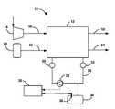
- FIG. 1is a schematic plan view of a fuel cell system including a fuel cell stack and a thermal sub-system;
- FIG. 2is a flow chart diagram showing a process for determining a loss of cooling fluid in the thermal sub-system shown in FIG. 1 .
- FIG. 1is a simplified schematic block diagram of a fuel cell system 10 including a fuel cell stack 12 .
- the fuel cell stack 12includes a cathode side that receives air from a compressor 14 on a cathode input line 16 and provides a cathode exhaust gas on a cathode exhaust gas line 18 .
- the fuel cell stack 12also includes an anode side that receives a hydrogen gas from a hydrogen source 20 , such as a high pressure tank, on an anode input line 22 and provides an anode exhaust gas on an anode exhaust gas line 24 .
- a hydrogen source 20such as a high pressure tank
- the anode exhaust and cathode exhaust from a fuel cell stackare combined into a single stack output.
- the system 10further includes a thermal sub-system that provides a cooling fluid flow to the fuel cell stack 12 .
- the thermal sub-systemincludes a high temperature pump 28 that pumps the cooling fluid through a coolant loop 26 external to the fuel cell stack 12 and through the cooling fluid flow channels in the bipolar plates in the fuel cell stack 12 .
- a temperature sensor 30measures the temperature of the cooling fluid in the coolant loop 26 as it enters the fuel cell stack 12 and a temperature sensor 32 measures the temperature of the cooling fluid in the coolant loop 26 as it exits the fuel cell stack 12 .
- a typical thermal sub-system for a fuel cell systemwill include a radiator for cooling the cooling fluid from the fuel cell stack 12 and a radiator by-pass line for by-passing the radiator, where the amount of cooling fluid that flows through the radiator and that by-passes the radiator is controlled by a suitable control element and valve to get the desired cooling fluid temperature.
- the thermal sub-systemalso includes an overflow tank 34 in fluid communication with the coolant loop 26 .
- a level indicator 36provides an indication of the level of the cooling fluid within the tank 34 .
- the present inventionproposes a method to detect a loss of cooling fluid in the thermal sub-system that utilizes pump current feedback to determine if the pump 28 is generating the expected work required to pump the cooling fluid through the coolant loop 26 .
- the pump currentis significantly reduced because the pump 28 is pumping air instead of cooling fluid.
- the estimated pump current and a measured pump currentcan be compared to determine low cooling fluid. Note that the change in current is relatively low over the full range and pump speed, and the resolution of current feedback has low sensitivity. For this reason, the diagnostic is only reliable at high pump speeds where a large delta current is expected between pumping cooling fluid versus air.
- the pump 28is not pumping significant cooling fluid.
- a diagnosticcould then be set and mitigation actions could be taken to prevent the fuel cell stack 12 from overheating. Caution must be taken from false positive diagnostics to prevent unnecessary remedial actions, such as a reduced power mode, which affects the driver.
- the present inventionproposes one protection against such a false diagnostic by implementing a diagnostic counter. If the counter reaches a predetermined threshold based on the active diagnostic sensing low cooling fluid in a predetermined time frame, the diagnostic is triggered. Alternately, the algorithm could use a predetermined count threshold in a predetermined allotment of time, such as five positive counts in 30 seconds.
- the system 10includes a controller 38 that receives a measured current signal from a sensor in the pump 28 identifying the pump current.
- the controller 38also receives a signal from the level indicator 36 indicating when the level of the cooling fluid in the tank 34 is low.
- the controller 38compares the measured current to the expected current, and if there is a significant discrepancy for a long enough period of time, will initiate mitigating actions, including providing a warning light to the driver and remedial mitigation actions for the system 10 .
- FIG. 2is a flow chart diagram 40 for determining a loss of cooling fluid from the thermal sub-system based on the discussion above.
- the algorithmresets all of the applicable buffers in the controller 38 and sets a counter to zero.
- the algorithmdetermines if the tank cooling fluid level sensor 36 indicates that the level of the cooling fluid in the tank 34 is below some level indicating low cooling fluid. If the sensor 36 does not indicate a low level of cooling fluid, then there is adequate cooling fluid in the thermal sub-system, and the algorithm returns to the box 42 to continue to monitor the sensor 36 .
- the algorithmcompares an estimated or predicted pump current based on system operating conditions to a measured pump current to determine if the measured pump current is some significant predetermined value less than the expected pump current for a predetermined period of time, such as two seconds, at decision diamond 44 . If the measured pump current is not less than the expected pump current for that period of time, then the algorithm returns to the decision diamond 42 to monitor the state of the cooling fluid level sensor 36 .
- the cooling fluid levelmay be quite low.
- the algorithmdetermines if the pump speed is greater than a predetermined speed threshold at decision diamond 48 .
- the algorithmchecks the pump speed because the process requires a high enough current draw from the pump 28 to be able to differentiate between a low cooling fluid condition and a normal cooling fluid condition. In other words, if the pump speed is too low, then the current measurement may have significant noise and oscillations, where the difference between the pumped cooling fluid and the pumped air is less than the resolution of the current sensor and could go undetected.
- the algorithmincrements a counter at box 50 , and determines if the count value of the counter is greater than a predetermined count threshold at decision diamond 52 , such as five counts.
- a predetermined count threshold at decision diamond 52such as five counts.
- the algorithmmakes sure that the pump current measurement is well below the estimated current for a long enough period of time so as to reduce the chance that the low pump current is for reasons other than a low cooling fluid. In one non-limiting embodiment, each count occurs every 30 seconds so that the total time that the measured current needs to be below the estimated current is about 2% minutes before the algorithm will take remedial measures. If the count is not greater than the threshold at the decision diamond 52 , then the algorithm returns to the decision diamond 46 to compare the currents. If the count is greater than the threshold at the decision diamond 52 , then the algorithm sets a cooling fluid loss diagnostic at box 54 to take remedial actions for a low cooling fluid, such as providing a warning light or shutting down the stack 12 .
- the algorithmcommands the pump speed to the threshold, such as 4000 rpm, at box 56 .
- the algorithmcompares the measured current to the estimated current as was done at the decision diamond 46 , at decision diamond 58 , because even if the measured current was significantly below the expected current for the required period of time at the decision diamond 46 , it may have been as a result of a low pump speed. As above, if the measured current is not significantly below the expected current for the required period of time at the decision diamond 58 , then the algorithm returns to the decision diamond 44 to monitor the level of the cooling fluid in the tank 34 .
- the algorithmincrements the counter at box 60 as was done at the box 50 . Likewise, the algorithm then determines whether the count is greater than the threshold at decision diamond 62 as was done at the decision diamond 52 , and, if it is not, returns to the box 58 to set the pump speed equal to the pump speed threshold. If the counter has reached the threshold at the decision diamond 64 , then the algorithm proceeds to the diagnostics box 54 . After the diagnostic is set at the box 54 , the algorithm will determine whether the pump speed needs to be reset at the box 42 to the desired pump speed if it has been increased at the box 56 . It is noted that the increased pump speed for the low cooling fluid algorithm discussed herein will not significantly affect the stack temperature while the diagnostic is being performed.
Landscapes
- Life Sciences & Earth Sciences (AREA)
- Engineering & Computer Science (AREA)
- Manufacturing & Machinery (AREA)
- Sustainable Development (AREA)
- Sustainable Energy (AREA)
- Chemical & Material Sciences (AREA)
- Chemical Kinetics & Catalysis (AREA)
- Electrochemistry (AREA)
- General Chemical & Material Sciences (AREA)
- Fuel Cell (AREA)
Abstract
Description
Claims (20)
Priority Applications (3)
| Application Number | Priority Date | Filing Date | Title |
|---|---|---|---|
| US13/082,046US8623567B2 (en) | 2011-04-07 | 2011-04-07 | Method to detect gross loss in coolant based on current feedback from the high temperature pump |
| DE102012102171.6ADE102012102171B4 (en) | 2011-04-07 | 2012-03-15 | A method of detecting a loss in a coolant based on a current feedback from the high temperature pump |
| CN201210098835.6ACN102738483B (en) | 2011-04-07 | 2012-04-06 | Method to detect gross loss in coolant based on current feedback from the high temperature pump |
Applications Claiming Priority (1)
| Application Number | Priority Date | Filing Date | Title |
|---|---|---|---|
| US13/082,046US8623567B2 (en) | 2011-04-07 | 2011-04-07 | Method to detect gross loss in coolant based on current feedback from the high temperature pump |
Publications (2)
| Publication Number | Publication Date |
|---|---|
| US20120255366A1 US20120255366A1 (en) | 2012-10-11 |
| US8623567B2true US8623567B2 (en) | 2014-01-07 |
Family
ID=46875310
Family Applications (1)
| Application Number | Title | Priority Date | Filing Date |
|---|---|---|---|
| US13/082,046Active2032-07-16US8623567B2 (en) | 2011-04-07 | 2011-04-07 | Method to detect gross loss in coolant based on current feedback from the high temperature pump |
Country Status (3)
| Country | Link |
|---|---|
| US (1) | US8623567B2 (en) |
| CN (1) | CN102738483B (en) |
| DE (1) | DE102012102171B4 (en) |
Families Citing this family (9)
| Publication number | Priority date | Publication date | Assignee | Title |
|---|---|---|---|---|
| CN106273020B (en)* | 2015-05-21 | 2018-07-24 | 湖南挚新科技发展有限公司 | A kind of portable intelligent water(Oil)Cooling means and device |
| JP6300844B2 (en)* | 2016-02-23 | 2018-03-28 | 本田技研工業株式会社 | Failure detection method for refrigerant pump and fuel cell system |
| JP6414155B2 (en)* | 2016-07-21 | 2018-10-31 | トヨタ自動車株式会社 | Fuel cell system |
| GB2565141B (en)* | 2017-08-04 | 2021-09-22 | Intelligent Energy Ltd | Devices and methods for controlling a fluid module |
| DE102017214726A1 (en)* | 2017-08-23 | 2019-02-28 | Audi Ag | Method for evaluating a coolant flow of a coolant circuit of a fuel cell system, fuel cell system and vehicle |
| CN107732339B (en)* | 2017-10-27 | 2020-04-24 | 吉利汽车研究院(宁波)有限公司 | Detection system for vehicle power battery pack, detection method thereof and vehicle |
| KR102506868B1 (en)* | 2017-12-15 | 2023-03-08 | 현대자동차주식회사 | Method for diagnosing lack of coolant |
| CN113241488B (en)* | 2021-05-06 | 2022-06-24 | 汉宇集团股份有限公司 | Cooling liquid pump assembly for power battery thermal management system and control method thereof |
| US12060930B1 (en) | 2023-04-26 | 2024-08-13 | Deere & Company | Sealing system for multiple fluids |
Citations (11)
| Publication number | Priority date | Publication date | Assignee | Title |
|---|---|---|---|---|
| US5118461A (en) | 1989-02-17 | 1992-06-02 | Kabushiki Kaisha Toshiba | Flow rate measuring apparatus |
| DE19737394C2 (en) | 1997-08-27 | 2003-02-27 | Schubert & Salzer Control Syst | System and method for determining a malfunction in the coolant circuit |
| US20060240297A1 (en)* | 2005-04-20 | 2006-10-26 | Kenji Takeda | Fuel cell unit and power generating system using the fuel cell unit |
| US20060269807A1 (en)* | 2003-07-30 | 2006-11-30 | Nobuo Fujita | Fuel cell cooling system and method for controlling circulation of cooling liquid in fuel cell |
| US20070065694A1 (en)* | 2005-09-22 | 2007-03-22 | Oliver Maier | Advanced control for an electrical heatable wax thermostat in the thermal coolant loop of fuel cell systems |
| US20070065695A1 (en)* | 2005-09-22 | 2007-03-22 | Oliver Maier | Coolant flow estimation for the thermal loop of a fuel cell system using stack loss power |
| US20080154187A1 (en)* | 2006-12-21 | 2008-06-26 | Lifescan, Inc. | Malfunction detection in infusion pumps |
| US20100300129A1 (en) | 2009-05-28 | 2010-12-02 | American Power Conversion Corporation | Systems and methods for detecting refrigerant leaks in cooling systems |
| US20110302941A1 (en)* | 2009-03-26 | 2011-12-15 | Mitsubishi Electric Corporation | Air-conditioning apparatus |
| US20120270325A1 (en)* | 2011-04-19 | 2012-10-25 | Ronald Kent Sperry | System and method for evaluating the performance of a pump |
| US20120318368A1 (en)* | 2011-06-16 | 2012-12-20 | Hamilton Sundstrand Corporation | Leak detection logic for closed-volume system |
Family Cites Families (3)
| Publication number | Priority date | Publication date | Assignee | Title |
|---|---|---|---|---|
| US4133373A (en)* | 1977-08-12 | 1979-01-09 | Inland Steel Company | Leak detecting apparatus |
| JP3920671B2 (en)* | 2002-03-14 | 2007-05-30 | 三洋電機株式会社 | Air conditioner |
| DE60312851T2 (en)* | 2003-08-28 | 2007-12-06 | Ford Global Technologies, LLC, Dearborn | Method and device for leak diagnosis in a container |
- 2011
- 2011-04-07USUS13/082,046patent/US8623567B2/enactiveActive
- 2012
- 2012-03-15DEDE102012102171.6Apatent/DE102012102171B4/enactiveActive
- 2012-04-06CNCN201210098835.6Apatent/CN102738483B/enactiveActive
Patent Citations (13)
| Publication number | Priority date | Publication date | Assignee | Title |
|---|---|---|---|---|
| US5118461A (en) | 1989-02-17 | 1992-06-02 | Kabushiki Kaisha Toshiba | Flow rate measuring apparatus |
| DE19737394C2 (en) | 1997-08-27 | 2003-02-27 | Schubert & Salzer Control Syst | System and method for determining a malfunction in the coolant circuit |
| US7662496B2 (en)* | 2003-07-30 | 2010-02-16 | Toyota Jidosha Kabushiki Kaisha | Fuel cell cooling system and method for controlling circulation of cooling liquid in fuel cell |
| US20060269807A1 (en)* | 2003-07-30 | 2006-11-30 | Nobuo Fujita | Fuel cell cooling system and method for controlling circulation of cooling liquid in fuel cell |
| US20060240297A1 (en)* | 2005-04-20 | 2006-10-26 | Kenji Takeda | Fuel cell unit and power generating system using the fuel cell unit |
| US20070065694A1 (en)* | 2005-09-22 | 2007-03-22 | Oliver Maier | Advanced control for an electrical heatable wax thermostat in the thermal coolant loop of fuel cell systems |
| US20070065695A1 (en)* | 2005-09-22 | 2007-03-22 | Oliver Maier | Coolant flow estimation for the thermal loop of a fuel cell system using stack loss power |
| US20080154187A1 (en)* | 2006-12-21 | 2008-06-26 | Lifescan, Inc. | Malfunction detection in infusion pumps |
| US7654127B2 (en)* | 2006-12-21 | 2010-02-02 | Lifescan, Inc. | Malfunction detection in infusion pumps |
| US20110302941A1 (en)* | 2009-03-26 | 2011-12-15 | Mitsubishi Electric Corporation | Air-conditioning apparatus |
| US20100300129A1 (en) | 2009-05-28 | 2010-12-02 | American Power Conversion Corporation | Systems and methods for detecting refrigerant leaks in cooling systems |
| US20120270325A1 (en)* | 2011-04-19 | 2012-10-25 | Ronald Kent Sperry | System and method for evaluating the performance of a pump |
| US20120318368A1 (en)* | 2011-06-16 | 2012-12-20 | Hamilton Sundstrand Corporation | Leak detection logic for closed-volume system |
Also Published As
| Publication number | Publication date |
|---|---|
| CN102738483B (en) | 2017-04-12 |
| CN102738483A (en) | 2012-10-17 |
| DE102012102171B4 (en) | 2018-03-29 |
| DE102012102171A1 (en) | 2012-10-11 |
| US20120255366A1 (en) | 2012-10-11 |
Similar Documents
| Publication | Publication Date | Title |
|---|---|---|
| US8623567B2 (en) | Method to detect gross loss in coolant based on current feedback from the high temperature pump | |
| US8524405B2 (en) | Detection of small anode leaks in fuel cell systems | |
| CN107342430B (en) | Fuel cell stack health monitoring using fuel cell stacks | |
| US7862949B2 (en) | Fuel cell reliability improvement by using stack end plate temperature sensors | |
| US8067127B2 (en) | Fuel cell system and control method thereof for detecting a chemical short | |
| WO2022233278A1 (en) | Online monitoring method and system for hydrogen fuel cell stack, and hydrogen fuel cell vehicle using monitoring method | |
| US8420271B2 (en) | Method to improve reliability of a fuel cell system using low performance cell detection at low power operation | |
| US10329150B2 (en) | Fuel cell system and method for determining purity level of hydrogen gas provided to an anode side of the fuel cell | |
| JP5194827B2 (en) | Fuel cell system | |
| US8660819B2 (en) | Utilization of HFR-based cathode inlet RH model in comparison to sensor feedback to determine failed water vapor transfer unit and utilize for a diagnostic code and message | |
| CN114914488B (en) | Fuel cell hydrogen deficiency detection and diagnosis method | |
| US8389170B2 (en) | Method to detect no coolant flow in a fuel cell system | |
| KR20110138443A (en) | Cooling water temperature prediction device and method in fuel cell system | |
| US20170250416A1 (en) | Fuel cell control method and fuel cell system | |
| US9080938B2 (en) | Extremum seeking algorithm in a variable time interval to detect anode pressure sensor stuck failure in a fuel cell system | |
| US10050288B2 (en) | Systems and methods for detecting leaks in a fuel cell system | |
| US9153828B2 (en) | Method to diagnose fuel cell humidification problems | |
| JP5555994B2 (en) | Fuel cell system | |
| JP2005135711A (en) | Abnormality detection device and fuel cell system | |
| JP5229364B2 (en) | Fuel cell system | |
| JP5077723B2 (en) | Fuel cell deterioration diagnosis device | |
| US20230282850A1 (en) | Fuel cell system | |
| US7682720B2 (en) | Diagnostic method for detecting a coolant pump failure in a fuel cell system by temperature measurement | |
| US20070104986A1 (en) | Diagnostic method for detecting a coolant pump failure in a fuel cell system by temperature measurement | |
| JP2012004136A (en) | Fuel cell system |
Legal Events
| Date | Code | Title | Description |
|---|---|---|---|
| AS | Assignment | Owner name:GM GLOBAL TECHNOLOGY OPERATIONS LLC, MICHIGAN Free format text:ASSIGNMENT OF ASSIGNORS INTEREST;ASSIGNORS:CAI, JUN;LERNER, SETH E.;DEVRIES, LOREN;AND OTHERS;REEL/FRAME:026176/0864 Effective date:20110331 | |
| AS | Assignment | Owner name:WILMINGTON TRUST COMPANY, DELAWARE Free format text:SECURITY AGREEMENT;ASSIGNOR:GM GLOBAL TECHNOLOGY OPERATIONS LLC;REEL/FRAME:028466/0870 Effective date:20101027 | |
| FEPP | Fee payment procedure | Free format text:PAYOR NUMBER ASSIGNED (ORIGINAL EVENT CODE: ASPN); ENTITY STATUS OF PATENT OWNER: LARGE ENTITY | |
| STCF | Information on status: patent grant | Free format text:PATENTED CASE | |
| AS | Assignment | Owner name:GM GLOBAL TECHNOLOGY OPERATIONS LLC, MICHIGAN Free format text:RELEASE BY SECURED PARTY;ASSIGNOR:WILMINGTON TRUST COMPANY;REEL/FRAME:034186/0776 Effective date:20141017 | |
| FPAY | Fee payment | Year of fee payment:4 | |
| MAFP | Maintenance fee payment | Free format text:PAYMENT OF MAINTENANCE FEE, 8TH YEAR, LARGE ENTITY (ORIGINAL EVENT CODE: M1552); ENTITY STATUS OF PATENT OWNER: LARGE ENTITY Year of fee payment:8 | |
| MAFP | Maintenance fee payment | Free format text:PAYMENT OF MAINTENANCE FEE, 12TH YEAR, LARGE ENTITY (ORIGINAL EVENT CODE: M1553); ENTITY STATUS OF PATENT OWNER: LARGE ENTITY Year of fee payment:12 |