US8623295B2 - Microfluidic system including a bubble valve for regulating fluid flow through a microchannel - Google Patents
Microfluidic system including a bubble valve for regulating fluid flow through a microchannelDownload PDFInfo
- Publication number
- US8623295B2 US8623295B2US13/245,331US201113245331AUS8623295B2US 8623295 B2US8623295 B2US 8623295B2US 201113245331 AUS201113245331 AUS 201113245331AUS 8623295 B2US8623295 B2US 8623295B2
- Authority
- US
- United States
- Prior art keywords
- reservoir
- microchannel
- flow channel
- bubble
- pressure
- Prior art date
- Legal status (The legal status is an assumption and is not a legal conclusion. Google has not performed a legal analysis and makes no representation as to the accuracy of the status listed.)
- Expired - Lifetime, expires
Links
Images


Classifications
- B—PERFORMING OPERATIONS; TRANSPORTING
- B01—PHYSICAL OR CHEMICAL PROCESSES OR APPARATUS IN GENERAL
- B01L—CHEMICAL OR PHYSICAL LABORATORY APPARATUS FOR GENERAL USE
- B01L3/00—Containers or dishes for laboratory use, e.g. laboratory glassware; Droppers
- B01L3/50—Containers for the purpose of retaining a material to be analysed, e.g. test tubes
- B01L3/502—Containers for the purpose of retaining a material to be analysed, e.g. test tubes with fluid transport, e.g. in multi-compartment structures
- B01L3/5027—Containers for the purpose of retaining a material to be analysed, e.g. test tubes with fluid transport, e.g. in multi-compartment structures by integrated microfluidic structures, i.e. dimensions of channels and chambers are such that surface tension forces are important, e.g. lab-on-a-chip
- B01L3/502738—Containers for the purpose of retaining a material to be analysed, e.g. test tubes with fluid transport, e.g. in multi-compartment structures by integrated microfluidic structures, i.e. dimensions of channels and chambers are such that surface tension forces are important, e.g. lab-on-a-chip characterised by integrated valves
- B—PERFORMING OPERATIONS; TRANSPORTING
- B01—PHYSICAL OR CHEMICAL PROCESSES OR APPARATUS IN GENERAL
- B01L—CHEMICAL OR PHYSICAL LABORATORY APPARATUS FOR GENERAL USE
- B01L3/00—Containers or dishes for laboratory use, e.g. laboratory glassware; Droppers
- B01L3/50—Containers for the purpose of retaining a material to be analysed, e.g. test tubes
- B01L3/502—Containers for the purpose of retaining a material to be analysed, e.g. test tubes with fluid transport, e.g. in multi-compartment structures
- B01L3/5027—Containers for the purpose of retaining a material to be analysed, e.g. test tubes with fluid transport, e.g. in multi-compartment structures by integrated microfluidic structures, i.e. dimensions of channels and chambers are such that surface tension forces are important, e.g. lab-on-a-chip
- B01L3/502761—Containers for the purpose of retaining a material to be analysed, e.g. test tubes with fluid transport, e.g. in multi-compartment structures by integrated microfluidic structures, i.e. dimensions of channels and chambers are such that surface tension forces are important, e.g. lab-on-a-chip specially adapted for handling suspended solids or molecules independently from the bulk fluid flow, e.g. for trapping or sorting beads, for physically stretching molecules
- B—PERFORMING OPERATIONS; TRANSPORTING
- B07—SEPARATING SOLIDS FROM SOLIDS; SORTING
- B07C—POSTAL SORTING; SORTING INDIVIDUAL ARTICLES, OR BULK MATERIAL FIT TO BE SORTED PIECE-MEAL, e.g. BY PICKING
- B07C5/00—Sorting according to a characteristic or feature of the articles or material being sorted, e.g. by control effected by devices which detect or measure such characteristic or feature; Sorting by manually actuated devices, e.g. switches
- B07C5/34—Sorting according to other particular properties
- F—MECHANICAL ENGINEERING; LIGHTING; HEATING; WEAPONS; BLASTING
- F16—ENGINEERING ELEMENTS AND UNITS; GENERAL MEASURES FOR PRODUCING AND MAINTAINING EFFECTIVE FUNCTIONING OF MACHINES OR INSTALLATIONS; THERMAL INSULATION IN GENERAL
- F16K—VALVES; TAPS; COCKS; ACTUATING-FLOATS; DEVICES FOR VENTING OR AERATING
- F16K99/00—Subject matter not provided for in other groups of this subclass
- F16K99/0001—Microvalves
- F16K99/0003—Constructional types of microvalves; Details of the cutting-off member
- F16K99/0017—Capillary or surface tension valves, e.g. using electro-wetting or electro-capillarity effects
- F—MECHANICAL ENGINEERING; LIGHTING; HEATING; WEAPONS; BLASTING
- F16—ENGINEERING ELEMENTS AND UNITS; GENERAL MEASURES FOR PRODUCING AND MAINTAINING EFFECTIVE FUNCTIONING OF MACHINES OR INSTALLATIONS; THERMAL INSULATION IN GENERAL
- F16K—VALVES; TAPS; COCKS; ACTUATING-FLOATS; DEVICES FOR VENTING OR AERATING
- F16K99/00—Subject matter not provided for in other groups of this subclass
- F16K99/0001—Microvalves
- F16K99/0003—Constructional types of microvalves; Details of the cutting-off member
- F16K99/0019—Valves using a microdroplet or microbubble as the valve member
- F—MECHANICAL ENGINEERING; LIGHTING; HEATING; WEAPONS; BLASTING
- F16—ENGINEERING ELEMENTS AND UNITS; GENERAL MEASURES FOR PRODUCING AND MAINTAINING EFFECTIVE FUNCTIONING OF MACHINES OR INSTALLATIONS; THERMAL INSULATION IN GENERAL
- F16K—VALVES; TAPS; COCKS; ACTUATING-FLOATS; DEVICES FOR VENTING OR AERATING
- F16K99/00—Subject matter not provided for in other groups of this subclass
- F16K99/0001—Microvalves
- F16K99/0034—Operating means specially adapted for microvalves
- F16K99/0036—Operating means specially adapted for microvalves operated by temperature variations
- F16K99/004—Operating means specially adapted for microvalves operated by temperature variations using radiation
- F—MECHANICAL ENGINEERING; LIGHTING; HEATING; WEAPONS; BLASTING
- F16—ENGINEERING ELEMENTS AND UNITS; GENERAL MEASURES FOR PRODUCING AND MAINTAINING EFFECTIVE FUNCTIONING OF MACHINES OR INSTALLATIONS; THERMAL INSULATION IN GENERAL
- F16K—VALVES; TAPS; COCKS; ACTUATING-FLOATS; DEVICES FOR VENTING OR AERATING
- F16K99/00—Subject matter not provided for in other groups of this subclass
- F16K99/0001—Microvalves
- F16K99/0034—Operating means specially adapted for microvalves
- F16K99/0042—Electric operating means therefor
- F16K99/0046—Electric operating means therefor using magnets
- F—MECHANICAL ENGINEERING; LIGHTING; HEATING; WEAPONS; BLASTING
- F16—ENGINEERING ELEMENTS AND UNITS; GENERAL MEASURES FOR PRODUCING AND MAINTAINING EFFECTIVE FUNCTIONING OF MACHINES OR INSTALLATIONS; THERMAL INSULATION IN GENERAL
- F16K—VALVES; TAPS; COCKS; ACTUATING-FLOATS; DEVICES FOR VENTING OR AERATING
- F16K99/00—Subject matter not provided for in other groups of this subclass
- F16K99/0001—Microvalves
- F16K99/0034—Operating means specially adapted for microvalves
- F16K99/0042—Electric operating means therefor
- F16K99/0048—Electric operating means therefor using piezoelectric means
- B—PERFORMING OPERATIONS; TRANSPORTING
- B01—PHYSICAL OR CHEMICAL PROCESSES OR APPARATUS IN GENERAL
- B01L—CHEMICAL OR PHYSICAL LABORATORY APPARATUS FOR GENERAL USE
- B01L2200/00—Solutions for specific problems relating to chemical or physical laboratory apparatus
- B01L2200/06—Fluid handling related problems
- B01L2200/0636—Focussing flows, e.g. to laminate flows
- B—PERFORMING OPERATIONS; TRANSPORTING
- B01—PHYSICAL OR CHEMICAL PROCESSES OR APPARATUS IN GENERAL
- B01L—CHEMICAL OR PHYSICAL LABORATORY APPARATUS FOR GENERAL USE
- B01L2200/00—Solutions for specific problems relating to chemical or physical laboratory apparatus
- B01L2200/06—Fluid handling related problems
- B01L2200/0647—Handling flowable solids, e.g. microscopic beads, cells, particles
- B—PERFORMING OPERATIONS; TRANSPORTING
- B01—PHYSICAL OR CHEMICAL PROCESSES OR APPARATUS IN GENERAL
- B01L—CHEMICAL OR PHYSICAL LABORATORY APPARATUS FOR GENERAL USE
- B01L2300/00—Additional constructional details
- B01L2300/08—Geometry, shape and general structure
- B01L2300/0809—Geometry, shape and general structure rectangular shaped
- B01L2300/0816—Cards, e.g. flat sample carriers usually with flow in two horizontal directions
- B—PERFORMING OPERATIONS; TRANSPORTING
- B01—PHYSICAL OR CHEMICAL PROCESSES OR APPARATUS IN GENERAL
- B01L—CHEMICAL OR PHYSICAL LABORATORY APPARATUS FOR GENERAL USE
- B01L2300/00—Additional constructional details
- B01L2300/08—Geometry, shape and general structure
- B01L2300/0861—Configuration of multiple channels and/or chambers in a single devices
- B01L2300/0864—Configuration of multiple channels and/or chambers in a single devices comprising only one inlet and multiple receiving wells, e.g. for separation, splitting
- B—PERFORMING OPERATIONS; TRANSPORTING
- B01—PHYSICAL OR CHEMICAL PROCESSES OR APPARATUS IN GENERAL
- B01L—CHEMICAL OR PHYSICAL LABORATORY APPARATUS FOR GENERAL USE
- B01L2300/00—Additional constructional details
- B01L2300/08—Geometry, shape and general structure
- B01L2300/089—Virtual walls for guiding liquids
- B—PERFORMING OPERATIONS; TRANSPORTING
- B01—PHYSICAL OR CHEMICAL PROCESSES OR APPARATUS IN GENERAL
- B01L—CHEMICAL OR PHYSICAL LABORATORY APPARATUS FOR GENERAL USE
- B01L2400/00—Moving or stopping fluids
- B01L2400/04—Moving fluids with specific forces or mechanical means
- B01L2400/0403—Moving fluids with specific forces or mechanical means specific forces
- B01L2400/0415—Moving fluids with specific forces or mechanical means specific forces electrical forces, e.g. electrokinetic
- B—PERFORMING OPERATIONS; TRANSPORTING
- B01—PHYSICAL OR CHEMICAL PROCESSES OR APPARATUS IN GENERAL
- B01L—CHEMICAL OR PHYSICAL LABORATORY APPARATUS FOR GENERAL USE
- B01L2400/00—Moving or stopping fluids
- B01L2400/06—Valves, specific forms thereof
- B—PERFORMING OPERATIONS; TRANSPORTING
- B01—PHYSICAL OR CHEMICAL PROCESSES OR APPARATUS IN GENERAL
- B01L—CHEMICAL OR PHYSICAL LABORATORY APPARATUS FOR GENERAL USE
- B01L2400/00—Moving or stopping fluids
- B01L2400/06—Valves, specific forms thereof
- B01L2400/0688—Valves, specific forms thereof surface tension valves, capillary stop, capillary break
- B—PERFORMING OPERATIONS; TRANSPORTING
- B01—PHYSICAL OR CHEMICAL PROCESSES OR APPARATUS IN GENERAL
- B01L—CHEMICAL OR PHYSICAL LABORATORY APPARATUS FOR GENERAL USE
- B01L2400/00—Moving or stopping fluids
- B01L2400/08—Regulating or influencing the flow resistance
- B01L2400/082—Active control of flow resistance, e.g. flow controllers
- B—PERFORMING OPERATIONS; TRANSPORTING
- B01—PHYSICAL OR CHEMICAL PROCESSES OR APPARATUS IN GENERAL
- B01L—CHEMICAL OR PHYSICAL LABORATORY APPARATUS FOR GENERAL USE
- B01L3/00—Containers or dishes for laboratory use, e.g. laboratory glassware; Droppers
- B01L3/50—Containers for the purpose of retaining a material to be analysed, e.g. test tubes
- B01L3/502—Containers for the purpose of retaining a material to be analysed, e.g. test tubes with fluid transport, e.g. in multi-compartment structures
- B01L3/5027—Containers for the purpose of retaining a material to be analysed, e.g. test tubes with fluid transport, e.g. in multi-compartment structures by integrated microfluidic structures, i.e. dimensions of channels and chambers are such that surface tension forces are important, e.g. lab-on-a-chip
- B01L3/502769—Containers for the purpose of retaining a material to be analysed, e.g. test tubes with fluid transport, e.g. in multi-compartment structures by integrated microfluidic structures, i.e. dimensions of channels and chambers are such that surface tension forces are important, e.g. lab-on-a-chip characterised by multiphase flow arrangements
- B01L3/502776—Containers for the purpose of retaining a material to be analysed, e.g. test tubes with fluid transport, e.g. in multi-compartment structures by integrated microfluidic structures, i.e. dimensions of channels and chambers are such that surface tension forces are important, e.g. lab-on-a-chip characterised by multiphase flow arrangements specially adapted for focusing or laminating flows
- F—MECHANICAL ENGINEERING; LIGHTING; HEATING; WEAPONS; BLASTING
- F16—ENGINEERING ELEMENTS AND UNITS; GENERAL MEASURES FOR PRODUCING AND MAINTAINING EFFECTIVE FUNCTIONING OF MACHINES OR INSTALLATIONS; THERMAL INSULATION IN GENERAL
- F16K—VALVES; TAPS; COCKS; ACTUATING-FLOATS; DEVICES FOR VENTING OR AERATING
- F16K99/00—Subject matter not provided for in other groups of this subclass
- F16K2099/0073—Fabrication methods specifically adapted for microvalves
- F16K2099/0074—Fabrication methods specifically adapted for microvalves using photolithography, e.g. etching
- F—MECHANICAL ENGINEERING; LIGHTING; HEATING; WEAPONS; BLASTING
- F16—ENGINEERING ELEMENTS AND UNITS; GENERAL MEASURES FOR PRODUCING AND MAINTAINING EFFECTIVE FUNCTIONING OF MACHINES OR INSTALLATIONS; THERMAL INSULATION IN GENERAL
- F16K—VALVES; TAPS; COCKS; ACTUATING-FLOATS; DEVICES FOR VENTING OR AERATING
- F16K99/00—Subject matter not provided for in other groups of this subclass
- F16K2099/0073—Fabrication methods specifically adapted for microvalves
- F16K2099/008—Multi-layer fabrications
- F—MECHANICAL ENGINEERING; LIGHTING; HEATING; WEAPONS; BLASTING
- F16—ENGINEERING ELEMENTS AND UNITS; GENERAL MEASURES FOR PRODUCING AND MAINTAINING EFFECTIVE FUNCTIONING OF MACHINES OR INSTALLATIONS; THERMAL INSULATION IN GENERAL
- F16K—VALVES; TAPS; COCKS; ACTUATING-FLOATS; DEVICES FOR VENTING OR AERATING
- F16K99/00—Subject matter not provided for in other groups of this subclass
- F16K2099/0082—Microvalves adapted for a particular use
- F16K2099/0084—Chemistry or biology, e.g. "lab-on-a-chip" technology
- G—PHYSICS
- G01—MEASURING; TESTING
- G01N—INVESTIGATING OR ANALYSING MATERIALS BY DETERMINING THEIR CHEMICAL OR PHYSICAL PROPERTIES
- G01N15/00—Investigating characteristics of particles; Investigating permeability, pore-volume or surface-area of porous materials
- G01N15/10—Investigating individual particles
- G01N15/14—Optical investigation techniques, e.g. flow cytometry
- G01N15/149—Optical investigation techniques, e.g. flow cytometry specially adapted for sorting particles, e.g. by their size or optical properties
- Y—GENERAL TAGGING OF NEW TECHNOLOGICAL DEVELOPMENTS; GENERAL TAGGING OF CROSS-SECTIONAL TECHNOLOGIES SPANNING OVER SEVERAL SECTIONS OF THE IPC; TECHNICAL SUBJECTS COVERED BY FORMER USPC CROSS-REFERENCE ART COLLECTIONS [XRACs] AND DIGESTS
- Y10—TECHNICAL SUBJECTS COVERED BY FORMER USPC
- Y10T—TECHNICAL SUBJECTS COVERED BY FORMER US CLASSIFICATION
- Y10T137/00—Fluid handling
- Y10T137/0318—Processes
- Y10T137/0396—Involving pressure control
- Y—GENERAL TAGGING OF NEW TECHNOLOGICAL DEVELOPMENTS; GENERAL TAGGING OF CROSS-SECTIONAL TECHNOLOGIES SPANNING OVER SEVERAL SECTIONS OF THE IPC; TECHNICAL SUBJECTS COVERED BY FORMER USPC CROSS-REFERENCE ART COLLECTIONS [XRACs] AND DIGESTS
- Y10—TECHNICAL SUBJECTS COVERED BY FORMER USPC
- Y10T—TECHNICAL SUBJECTS COVERED BY FORMER US CLASSIFICATION
- Y10T137/00—Fluid handling
- Y10T137/0318—Processes
- Y10T137/0402—Cleaning, repairing, or assembling
- Y10T137/0491—Valve or valve element assembling, disassembling, or replacing
- Y10T137/0497—Fluid actuated or retarded
- Y—GENERAL TAGGING OF NEW TECHNOLOGICAL DEVELOPMENTS; GENERAL TAGGING OF CROSS-SECTIONAL TECHNOLOGIES SPANNING OVER SEVERAL SECTIONS OF THE IPC; TECHNICAL SUBJECTS COVERED BY FORMER USPC CROSS-REFERENCE ART COLLECTIONS [XRACs] AND DIGESTS
- Y10—TECHNICAL SUBJECTS COVERED BY FORMER USPC
- Y10T—TECHNICAL SUBJECTS COVERED BY FORMER US CLASSIFICATION
- Y10T137/00—Fluid handling
- Y10T137/206—Flow affected by fluid contact, energy field or coanda effect [e.g., pure fluid device or system]
- Y10T137/2076—Utilizing diverse fluids
- Y—GENERAL TAGGING OF NEW TECHNOLOGICAL DEVELOPMENTS; GENERAL TAGGING OF CROSS-SECTIONAL TECHNOLOGIES SPANNING OVER SEVERAL SECTIONS OF THE IPC; TECHNICAL SUBJECTS COVERED BY FORMER USPC CROSS-REFERENCE ART COLLECTIONS [XRACs] AND DIGESTS
- Y10—TECHNICAL SUBJECTS COVERED BY FORMER USPC
- Y10T—TECHNICAL SUBJECTS COVERED BY FORMER US CLASSIFICATION
- Y10T137/00—Fluid handling
- Y10T137/206—Flow affected by fluid contact, energy field or coanda effect [e.g., pure fluid device or system]
- Y10T137/2082—Utilizing particular fluid
- Y—GENERAL TAGGING OF NEW TECHNOLOGICAL DEVELOPMENTS; GENERAL TAGGING OF CROSS-SECTIONAL TECHNOLOGIES SPANNING OVER SEVERAL SECTIONS OF THE IPC; TECHNICAL SUBJECTS COVERED BY FORMER USPC CROSS-REFERENCE ART COLLECTIONS [XRACs] AND DIGESTS
- Y10—TECHNICAL SUBJECTS COVERED BY FORMER USPC
- Y10T—TECHNICAL SUBJECTS COVERED BY FORMER US CLASSIFICATION
- Y10T137/00—Fluid handling
- Y10T137/206—Flow affected by fluid contact, energy field or coanda effect [e.g., pure fluid device or system]
- Y10T137/218—Means to regulate or vary operation of device
- Y10T137/2191—By non-fluid energy field affecting input [e.g., transducer]
- Y10T137/2196—Acoustical or thermal energy
- Y—GENERAL TAGGING OF NEW TECHNOLOGICAL DEVELOPMENTS; GENERAL TAGGING OF CROSS-SECTIONAL TECHNOLOGIES SPANNING OVER SEVERAL SECTIONS OF THE IPC; TECHNICAL SUBJECTS COVERED BY FORMER USPC CROSS-REFERENCE ART COLLECTIONS [XRACs] AND DIGESTS
- Y10—TECHNICAL SUBJECTS COVERED BY FORMER USPC
- Y10T—TECHNICAL SUBJECTS COVERED BY FORMER US CLASSIFICATION
- Y10T137/00—Fluid handling
- Y10T137/206—Flow affected by fluid contact, energy field or coanda effect [e.g., pure fluid device or system]
- Y10T137/218—Means to regulate or vary operation of device
- Y10T137/2202—By movable element
- Y10T137/2207—Operating at timed intervals [e.g., to produce pulses]
- Y—GENERAL TAGGING OF NEW TECHNOLOGICAL DEVELOPMENTS; GENERAL TAGGING OF CROSS-SECTIONAL TECHNOLOGIES SPANNING OVER SEVERAL SECTIONS OF THE IPC; TECHNICAL SUBJECTS COVERED BY FORMER USPC CROSS-REFERENCE ART COLLECTIONS [XRACs] AND DIGESTS
- Y10—TECHNICAL SUBJECTS COVERED BY FORMER USPC
- Y10T—TECHNICAL SUBJECTS COVERED BY FORMER US CLASSIFICATION
- Y10T137/00—Fluid handling
- Y10T137/206—Flow affected by fluid contact, energy field or coanda effect [e.g., pure fluid device or system]
- Y10T137/218—Means to regulate or vary operation of device
- Y10T137/2202—By movable element
- Y10T137/2213—Electrically-actuated element [e.g., electro-mechanical transducer]
- Y—GENERAL TAGGING OF NEW TECHNOLOGICAL DEVELOPMENTS; GENERAL TAGGING OF CROSS-SECTIONAL TECHNOLOGIES SPANNING OVER SEVERAL SECTIONS OF THE IPC; TECHNICAL SUBJECTS COVERED BY FORMER USPC CROSS-REFERENCE ART COLLECTIONS [XRACs] AND DIGESTS
- Y10—TECHNICAL SUBJECTS COVERED BY FORMER USPC
- Y10T—TECHNICAL SUBJECTS COVERED BY FORMER US CLASSIFICATION
- Y10T137/00—Fluid handling
- Y10T137/206—Flow affected by fluid contact, energy field or coanda effect [e.g., pure fluid device or system]
- Y10T137/2224—Structure of body of device
- Y—GENERAL TAGGING OF NEW TECHNOLOGICAL DEVELOPMENTS; GENERAL TAGGING OF CROSS-SECTIONAL TECHNOLOGIES SPANNING OVER SEVERAL SECTIONS OF THE IPC; TECHNICAL SUBJECTS COVERED BY FORMER USPC CROSS-REFERENCE ART COLLECTIONS [XRACs] AND DIGESTS
- Y10—TECHNICAL SUBJECTS COVERED BY FORMER USPC
- Y10T—TECHNICAL SUBJECTS COVERED BY FORMER US CLASSIFICATION
- Y10T29/00—Metal working
- Y10T29/49—Method of mechanical manufacture
- Y10T29/49405—Valve or choke making
- Y—GENERAL TAGGING OF NEW TECHNOLOGICAL DEVELOPMENTS; GENERAL TAGGING OF CROSS-SECTIONAL TECHNOLOGIES SPANNING OVER SEVERAL SECTIONS OF THE IPC; TECHNICAL SUBJECTS COVERED BY FORMER USPC CROSS-REFERENCE ART COLLECTIONS [XRACs] AND DIGESTS
- Y10—TECHNICAL SUBJECTS COVERED BY FORMER USPC
- Y10T—TECHNICAL SUBJECTS COVERED BY FORMER US CLASSIFICATION
- Y10T436/00—Chemistry: analytical and immunological testing
- Y10T436/14—Heterocyclic carbon compound [i.e., O, S, N, Se, Te, as only ring hetero atom]
- Y10T436/142222—Hetero-O [e.g., ascorbic acid, etc.]
- Y10T436/143333—Saccharide [e.g., DNA, etc.]
- Y—GENERAL TAGGING OF NEW TECHNOLOGICAL DEVELOPMENTS; GENERAL TAGGING OF CROSS-SECTIONAL TECHNOLOGIES SPANNING OVER SEVERAL SECTIONS OF THE IPC; TECHNICAL SUBJECTS COVERED BY FORMER USPC CROSS-REFERENCE ART COLLECTIONS [XRACs] AND DIGESTS
- Y10—TECHNICAL SUBJECTS COVERED BY FORMER USPC
- Y10T—TECHNICAL SUBJECTS COVERED BY FORMER US CLASSIFICATION
- Y10T436/00—Chemistry: analytical and immunological testing
- Y10T436/25—Chemistry: analytical and immunological testing including sample preparation
- Y10T436/25375—Liberation or purification of sample or separation of material from a sample [e.g., filtering, centrifuging, etc.]
Definitions
- the present inventionrelates to microscale fluid handling devices and systems. More particularly, the present invention relates to a method and system for controlling liquid flow in a microchannel by the introduction of a gas bubble to a microfluidic system.
- Microfluidic devices and systemsprovide improved methods of performing chemical, biochemical and biological analysis and synthesis. Microfluidic devices and systems allow for the performance of multi-step, multi-species chemical operations in chip-based micro chemical analysis systems.
- Chip-based microfluidic systemsgenerally comprise conventional ‘microfluidic’ elements, particularly capable of handling and analyzing chemical and biological specimens.
- microfluidic in the artrefers to systems or devices having a network of processing nodes, chambers and reservoirs connected by channels, in which the channels have typical cross-sectional dimensions in the range between about 1.0 ⁇ m and about 500 ⁇ m. In the art, channels having these cross-sectional dimensions are referred to as ‘microchannels’.
- Downscaling dimensionsallows for diffusional processes, such as heating, cooling and passive transport of species (diffusional mass-transport), to proceed faster.
- diffusional processessuch as heating, cooling and passive transport of species (diffusional mass-transport)
- thermal processing of liquidswhich is typically a required step in chemical synthesis and analysis.
- thermal processing of liquidsis accelerated in a microchannel due to reduced diffusional distances.
- Another example of the efficiency of microfluidic systemsis the mixing of dissolved species in a liquid, a process that is also diffusion limited.
- Milliliter-sized systemstypically require milliliter volumes of these substances, while microliter sized microfluidic systems only require microliters volumes.
- the ability to perform these processes using smaller volumesresults in significant cost savings, allowing the economic operation of chemical synthesis and analysis operations.
- the amount of chemical waste produced during the chemical operationsis correspondingly reduced.
- a flow control devicemay be used to regulate the flow of liquid through a microchannel. Regulation includes control of flow rate, impeding of flow, switching of flows between various input channels and output channels as well as volumetric dosing.
- valves in the prior artuse electrochemical means to produce a bubble in a liquid.
- the microfluidic systemincludes a microchannel and a sealed, gas-filled reservoir positioned adjacent to and connected to the microchannel.
- the gas filled reservoirhas a movable wall and a meniscus formed by a liquid in the microchannel that forms an interface between the reservoir and the microchannel interior.
- the meniscusmay form a portion of the side wall of the microchannel.
- An external mechanical actuatormay be used to deflect the movable wall of the reservoir. As the movable wall is deflected, the volume of the reservoir decreases and the gas pressure inside the reservoir increases, causing the meniscus to deflect into the microchannel, thereby modifying the cross-sectional area of the microchannel and consequently varying the flow of liquid through the channel.
- the increased pressure in the reservoirpushes gas from the reservoir into the microchannel.
- the gasmay result in a local gas bubble being forced into the microchannel from the gas-filled reservoir.
- the resulting gas bubbleoccupies a portion of the cross-section of the channel, allowing liquid flow through the channel to be effectively controlled by controlling the size of the gas bubble via the external actuator.
- the meniscusmay comprise a virtual wall formed in a side wall of the microchannel.
- the virtual wallis a meniscus formed by a liquid in the microchannel that fills an aperture formed in the side wall of the microchannel and essentially replaces the removed portion of the side wall without affecting the properties of liquid flow through the channel.
- a gas bubblecan be forced into the channel by applying a gas pressure at the opening using an external pneumatic actuator. The gas pressure forces the meniscus inside the channel, which varies the flow of liquid through the channel interior.
- the microchannelincludes a hydrophobic patch spanning the width of the microchannel at the location where the gas bubble is introduced to enhanced on-off switching of the bubble valve.
- the hydrophobic patchanchors the bubble in a particular location in the microchannel. If the introduced gas bubble covers the whole area of the patch, the bubble is effectively retained by capillary forces and blocks any liquid flow up to a certain pressure difference, depending on the level of hydrophobicity of the patch.
- the microchannelcan be locally shaped into a cavity for receiving and anchoring the gas bubble.
- the bubblecan be kept in place during operation, reducing the risk that the gas bubble is carried away with the liquid.
- a microfluidic devicecomprises a microchannel having an interior bounded by a side wall and a valve for regulating the flow of fluid through the microchannel.
- the valvecomprises a gas-filled reservoir, a fluid meniscus interfacing the reservoir and the interior and an actuator for varying the volume of the reservoir to increase an internal pressure of the reservoir to vary the flow of liquid through the channel.
- a microfluidic devicecomprising a first plate having a groove formed therein defining a microchannel, a second plate for enclosing the microchannel and a flexible membrane.
- the second plateis bonded to the first plate and has an aperture adjacent to the groove sized and dimensioned to form a meniscus when the microchannel is filled with a liquid.
- the aperturedefines a reservoir adjacent to the microchannel, wherein the meniscus forms an interface between the microchannel and the reservoir.
- the flexible membraneis bonded to the second plate to seal the reservoir.
- a method of making a bubble valvecomprises providing a microchannel having an interior bounded by a side wall, an aperture formed in the side wall and a valve chamber adjacent to the aperture in communication with the interior, filling the microchannel with a liquid to form a meniscus of the liquid in the aperture, whereby the step of filling traps a gas in the valve chamber and providing an actuator for increasing the pressure in the valve chamber to deflect the meniscus into the interior.
- a method of making a bubble valvecomprises providing a microchannel having an interior bounded by a side wall, an aperture formed in the side wall and a valve chamber adjacent to the aperture in communication with the interior, filling the microchannel with a liquid to form a meniscus of the liquid in the aperture and applying and sealing an actuator comprising a chamber to a top surface of the microchannel to form a gas-filled chamber adjacent to the meniscus.
- the actuatorvaries the pressure in the gas-filled chamber to deflect the meniscus into the interior, thereby regulating fluid flow.
- a microfluidic devicecomprising a microchannel having an interior bounded by a side wall, a bubble valve for creating and injecting a bubble into the microchannel interior to regulate fluid flow through the microchannel and a hydrophobic patch for retaining the bubble in a predetermined position in the microchannel interior.
- a bubble valve in a particle sorting devicefor separating particles having a predetermined characteristic from particles not having a predetermined characteristic.
- the bubble valvecomprises a gas-filled reservoir, a side channel in communication with a channel through which a stream of particles in a carrier fluid passes, wherein the carrier fluid forms a meniscus in the side channel adjacent to the gas-filled reservoir and an actuator for deflecting the meniscus to create a pressure pulse to selectively deflect a particle having the predetermined characteristic from the stream of particles.
- an electrophoretic systemcomprising an electrokinetically operated microchannel, a sample well for providing an sample to the microchannel, a voltage source and a bubble valve for injecting a bubble into the microchannel to vary the electrical resistance of the microchannel.
- an electrokinetic column to column switchcomprising a first electrokinetically operated microchannel, a second electrokinetically operated microchannel in communication with the first electrokinetically operated microchannel and a bubble valve for selectively blocking flow from the first electrokinetically operated microchannel to the second electrokinetically operated microchannel by selectively injecting a bubble into a microchannel.
- FIG. 1is a schematic view of a microfluidic system suitable for implementing the illustrative embodiment of the invention.
- FIG. 2shows an exploded view of a bubble valve according to an illustrative embodiment of the present invention.
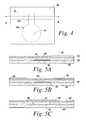
- FIG. 4shows a top view of the bubble valve of FIG. 2 .
- FIG. 6shows an exploded view of an alternative embodiment of a bubble valve according to the present invention.
- FIG. 7shows a top view of the bubble valve of FIG. 6 .
- FIG. 9shows an application of the bubble valve of an illustrative embodiment of the present invention in a microchannel.
- FIG. 10shows a Y-intersection in a microfluidic system of an embodiment of the invention that implements a bubble valve to control liquid flow according to the teachings of the present invention.
- FIG. 11shows a Y-intersection in a microfluidic system of another embodiment of the invention that implements a bubble valve to control liquid flow according to the teachings of the present invention.
- FIG. 13 ashows an electrokinetic column-column switch implementing a bubble valve according to the teachings of the present invention.
- FIG. 13 bshows an alternate electrokinetic column-column switch implementing a bubble valve according to another embodiment of the present invention.
- FIG. 15shows an alternative selective resistance circuit that employs a bubble valve to control electrical current according to the teachings of the present invention.
- FIG. 16shows a particle sorting system that implements a bubble valve of the present invention to produce fluid impulses to sort particles.
- FIGS. 17 a , 17 b and 17 cillustrate the operation of the particle sorting system of FIG. 16 .
- the present inventionprovides an improved bubble valve for controlling fluid flow through a microchannel in a microfluidic system.
- the inventionfurther provides a method of forming the bubble valve.
- the bubble valve of the present inventioncan be applied in numerous microfluidic systems for controlling and switching fluid flows. Examples of suitable applications include, but are not limited to: flow cytometry, column switching, 2-D separations, cell or particle sorting applications on a chip, regulating pressurized fluid flows including on-off switching, regulating electrokinetic fluid flows and electrokinetically induced processes including on-off switching and electrokinetic sample injection and channel to channel switching.
- FIG. 1illustrates a microfluidic system suitable for implementing the illustrative embodiment of the present invention.
- the illustrative microfluidic system 100comprises a substrate 101 having one or more microchannels 21 disposed therein.
- the microchannelstransport fluid through the microfluidic system 100 for processing, handling, and/or performing any suitable operation on a liquid sample.
- microfluidicrefers to a system or device for handling, processing, ejecting and/or analyzing a fluid sample including at least one channel having microscale dimensions.
- channelrefers to a pathway formed in or through a medium that allows for movement of fluids, such as liquids and gases.
- microchannelrefers to a channel preferably formed in a microfluidic system or device having cross-sectional dimensions in the range between about 1.0 ⁇ m and about 500 ⁇ m, preferably between about 25 ⁇ m and about 250 ⁇ m and most preferably between about 50 ⁇ m and about 100 ⁇ m.
- the rangesare intended to include the above-recited values as upper or lower limits.
- the microchannelcan have any selected shape or arrangement, examples of which include a linear or non-linear configuration and a U-shaped configuration.
- the microfluidic system 100may comprise any suitable number of microchannels 21 for transporting fluids through the microfluidic system 100 .
- the microfluidic system 100includes a bubble valve 10 , 10 ′ shown in FIGS. 2-8 c for controlling liquid flow through a microchannel of the system.
- the microchannelis defined by a side wall having any suitable shape enclosing at least a portion of the interior of the channel.
- the bubble valvemay be formed by a gas-filled reservoir positioned adjacent to the microchannel including a meniscus that forms the interface between the reservoir and the microchannel interior. The meniscus may form a portion of the side wall of the microchannel.
- the bubble valveincludes an actuator for modifying the pressure in the reservoir to deflect the meniscus into the channel interior, thereby modifying the cross-sectional area of the microchannel and consequently varying the flow of liquid through the channel.
- the bubble valveis formed by a meniscus in a separate side channel that communicates with and intersects a microchannel through which a liquid to be controlled flows.
- the meniscuscan be located at any location relative to the microchannel through which liquid flows.
- the gas-filled reservoirmay be formed when filling the microchannel having an aperture in a side wall and a reservoir formed adjacent to the aperture.
- An empty microchannelmay be filled with liquid, forming the meniscus in the aperture, which traps the gas that forms the gas bubble and forms a gas pocket in the reservoir adjacent to the meniscus.
- the creation of the gas pocket on fillingprovides a sterile gas bubble and reduces contaminants in the system.
- the air pocketmay be created by introducing a gas to the reservoir after filling of the microchannel.
- FIG. 2shows an exploded view of an embodiment of an illustrative bubble valve 10 of the present invention.
- the microfluidic systemmay be formed by a plurality of stacked layers.
- the illustrative microfluidic system 100includes a first plate 20 in which a groove defining the microchannel 21 is provided.
- a hydrophobic patch 22may be applied to an inner wall of the microchannel 21 .
- a second plate 30 for enclosing the microchannelis bonded to the first plate 20 and includes an aperture 31 .
- a third plate 40is bonded on top of second plate 30 to close and seal the stacked structure.
- the aperture 31 of the intermediate second plate 30defines a void in the system adjacent to the microchannel 21 .
- FIGS. 3 and 4illustrates the assembled bubble valve 10 .
- the stacked first plate 20 , second plate 30 and third plate 40define a closed, gas filled gas reservoir 70 , which can be actuated with a displacement actuator 50 .
- the aperture 31 defining the reservoir 70comprises a main body 31 a and a slot 31 b extending from the main body 31 a .
- the slot 31 b of the aperture 31defines a gap in the side wall of the microchannel 21 that provides access to and communicates with the interior of the microchannel 21 .
- the bubble valve 10operates to control the flow of liquid through the microchannel 21 .
- a meniscusis formed in the aperture 31 , which interfaces with and separates the microchannel interior from the reservoir 70 .
- the meniscusis formed by a liquid filling the microchannel in the slot 31 b .
- the liquid in the slot 31 bis retained in the microchannel by capillary forces.
- the actuator 50deflects the upper wall of the reservoir, defined by plate 40 , which decreases the volume of the reservoir 70 .
- the actuator 50may comprise any suitable device for deflecting the wall, such as an electromagnetic actuator or a piezoelectric element.
- the plate 40may comprises a flexible membrane.
- the decreased volumeconsequently increases the pressure of the reservoir 70 and causes the meniscus 80 to deflect into the channel interior to create a constriction in the channel, thereby impeding fluid flow or pushing fluid away from the meniscus. If a sufficient pressure is applied to the meniscus, the actuator generates and enlarges a bubble in the liquid of the microchannel, which blocks fluid flow.
- the hydrophobic patch 22provides an anchor for the bubble and retains the bubble at a selected location in the microchannel.
- FIGS. 5 a - cillustrate the operation of the bubble valve according to the teachings of the invention.
- FIG. 5 ashows the bubble valve in an ‘open’ state.
- the meniscus between the reservoir and the interior of the microchannelis defined by the meniscus 80 , formed by the liquid 60 in the slot 31 b in the second plate 30 .
- the ‘open’ stateliquid flows freely through the microchannel 21 and the valve does not impose any additional flow resistance in the channel.
- the slot 31 bmay be sized and dimensioned to form a “virtual wall” in the microchannel.
- “virtual wall”refers to the meniscus 80 formed by the first liquid 60 in the aperture formed in the side wall of the microchannel 20 , which essentially replaces the removed portion of the side wall without affecting the properties of the microchannel.
- the meniscus surfacecan be, although not required, substantially co-planar with the wall of the microchannel in which the meniscus is formed.
- the word “virtual”is chosen to express the effect that the overall liquid flow through the microchannel 21 of the microfluidic system 100 is not influenced by the virtual wall, i.e.
- the flow of liquid in the microfluidic system having a virtual wallis substantially identical to the flow of liquid through an identical microfluidic system in which no virtual wall is present.
- the meniscusmay be convex or concave, depending on the appropriate system pressure.
- the bubble valve 10switches to a “pinched” state, as shown in FIG. 5 b , to inhibit fluid flow through the channel interior.
- the actuator 50deflects the top of the gas reservoir 70 for a certain fraction, increasing the pressure in the reservoir 70 and forcing the meniscus 80 down into the channel 21 .
- the deflection of the meniscuslocally reduces the cross-section of the channel 21 and introduces an additional flow resistance to the liquid flow.
- the degree of reduction in the liquid flow through the microchannelcorresponds to the amplitude, frequency and duration of the displacement of the meniscus 80 , which are controllable by the actuator 50 .
- any suitable means for varying the pressure within the reservoir 70may be used to deflect the meniscus 80 , thereby regulating fluid flow.
- the bubble valve 10When the actuator is fully actuated, the bubble valve 10 is switched to a closed state, as illustrated in FIG. 5 c .
- the closed statethe meniscus 80 deflects fully to form and introduce a gas bubble 81 into the microchannel 21 .
- the gas bubble 81is retained by the hydrophobic patch 22 formed in the channel wall opposite the slot 31 b .
- the liquid flow in the channelis substantially blocked.
- the bubble valve 10can be brought from the ‘closed’ state of FIG. 5 c via the ‘pinched’ state of FIG. 5 b back to the ‘open’ state of FIG. 5 a.
- the bubble valve 10may be used as a check valve for regulating pressure in the microchannel.
- the pressure in the microchannelexceeds a maximum breaking pressure, the bubble collapses, opening the valve and allowing fluid to flow through the channel, thereby reducing the pressure in the microchannel.
- the breaking pressuredepends on the hydrophobicity of the hydrophobic patch 22 , as well as the geometry of the microchannel.
- the microchannel 21can be locally shaped into a cavity for receiving and anchoring the gas bubble 81 .
- the bubblecan be kept in place during operation, reducing the risk that the gas bubble is carried away with the liquid.
- the actuator 50is integrated in the microfluidic chip 100 .
- an external, reusable actuatormay also be used to control formation of a gas bubble in the microchannel.
- FIG. 6shows an alternative embodiment of a microfluidic system 100 ′ including a bubble valve 10 ′ having an external actuator 90 according to the teachings of the invention.
- the microfluidic system 100 ′includes a first plate 200 including a groove defining the microchannel 210 and a second plate 300 bonded to the first plate 200 for enclosing the microchannel 210 and in which a virtual wall opening 32 is formed.
- the virtual wall opening 32is sized and dimensioned to form a “virtual wall” when the microchannel 210 is filled with a liquid.
- the microfluidic systemUpon filling of the microchannel 21 with a liquid, a virtual wall 32 a is formed in virtual wall opening 32 .
- the microfluidic systemfurther includes an external actuator, illustrated as pressurizer 90 , pressed and sealed onto the top of the second plate 300 to form a tight seal.
- the external pressurizer 90defines a sealed pressurizing chamber 92 adjacent to the virtual wall 32 a .
- the pressurizervaries the pressure within the pressurizing chamber 92 to control liquid flow through the microchannel 210 by modifying the position of the virtual wall.
- the pressurizer 90may include a source of pressurized gas (not shown) and a gas inlet 91 to allow a gas pressure to be applied to the virtual wall 32 a in order to move the virtual wall.
- the pressurizermay alternatively include a flexible wall that deflects to vary the volume of the chamber 92 upon activation of an actuator, such as a piezoelectric element or electromagnetic actuator.
- FIG. 8 ashows a cross-section of the bubble valve 10 ′ of FIGS. 6 and 7 in the ‘open’ state.
- a virtual wall 32 adefined by a meniscus 800 , is formed within the virtual wall opening 32 .
- the meniscusessentially replaces the absent portion of the side wall of the microchannel and allows liquid to flow through the channel interior unimpeded and uninfluenced by the virtual wall.
- FIG. 8 bdepicts the ‘pinched’ state of the bubble valve, when the pressurizer 90 is activated.
- activation of the pressurizer 90increases the internal pressure within the pressurizing chamber 92 .
- the increased pressuremoves the meniscus 800 down the channel height and into the microchannel interior, thereby regulating liquid flow.
- the pressurizedcontrols the level of the internal pressure in order to control the amount of deflection of the meniscus and therefore the rate of fluid flow.
- the pressurizer 90applies a large pressure that is sufficient to form and introduce a gas bubble 810 into the channel 210 .
- the hydrophobic patch 220retains the gas bubble 810 in place.
- the liquid flow in the channelis blocked up to a ‘breaking pressure’, which depends on the hydrophobicity of hydrophobic patch 220 .
- a higher hydrophobicityresults in a larger breaking pressure.
- FIG. 9shows an application of a bubble valve 10 for flow regulation in a microchannel 121 according to one embodiment of the invention.
- a pressure differenceis applied over the length of a microchannel 121 .
- a bubble valve 10can be employed to regulate the flow through the microchannel between zero and a maximum flow rate, depending on the applied pressure difference.
- FIG. 10shows a portion of a microfluidic system according to an embodiment of the invention forming a Y-intersection comprising two inlet microchannels 121 a and 121 b and an outlet channel 121 c that combines the fluids flowing through the two inlet microchannels.
- the first microchannel 121 acarries a first liquid and the second microchannel 121 b carries a second liquid.
- the microchannels 121 a and 121 bare each controlled by a corresponding bubble valve, 10 a and 10 b , respectively, for regulating the combined composition and flow rate through the outlet microchannel 121 c .
- the number of inlet channelsis not limited to two, but is presented here merely as an example.
- FIG. 11shows a Y-intersection of a microfluidic system according to another embodiment of the invention.
- the Y-intersectioncomprises an inlet microchannel 221 c and two outlet microchannels 221 a and 221 b for splitting the incoming liquid flow from the inlet microchannel 221 c .
- the flow of each outlet channelis regulated by a corresponding bubble valve 200 a and 200 b , respectively.
- the incoming liquid flow from the inlet microchannel 221 ccan be split between microchannel 221 a and microchannel 221 b in any required ratio.
- the number of inlet channelsis not limited to two, but is presented here merely as an example.
- FIG. 12 a - 12 cshows the implementation of an electrophoresis system 110 comprising five bubble valves, 10 a - e of the present invention, arranged with a crossed microchannel configuration.
- Regulation of the bubble valve 10 aregulates the electric current through the associated electrokinetically operated microchannel 115 a .
- the pinching of the liquid in the electrokinetically operated microchannel 115 a by a bubble valvewill result in an increased electrical resistance in the microchannel 115 a .
- the migration of charged species and electro-osmotic flow in the electrokinetically operated microchannel 115 acan be regulated.
- a voltages difference for the injection of sample from a well storing a supply of a sample 125 between the bubble valve 10 a and the crossing point 111 of the microchannels and consecutive separationare provided via wells V+ and V 0 . Electrodes are placed in the V+ and V 0 wells and energized with a constant voltage difference during the operation of the electrophoresis system.
- valves 10 a , 10 b , 10 c and 10 dare substantially in the open position, allowing passage of electrical current up to a required level for injection ( FIG. 12 b shows direction of current/sample), while bubble valve 10 e is closed.
- the valvesare kept in this position long enough for the sample to move from the sample well 125 towards and past the central injection crossing 111 .
- Varying the opening ratio of valves 10 a , 10 b and 10 dcan be adjusted to confine the sample to a narrow flow through the injection cross 111 , as shown in FIG. 12 c (i.e. ‘pinched injection’).
- a plug of sampleis injected and separated in the separation column 115 a (microchannel which runs horizontally in figure) by closing bubble valves 10 a , 10 d and 10 c and opening valves 10 b and 10 e .
- the total voltage differenceis applied longitudinally over the separation channel, resulting in the separation of the constituents in the sample ( FIG. 12 c ).
- FIG. 13 aillustrates another application of the bubble valve of the present invention implemented in a column-column switch 130 for electrokinetically transferring a substance from a first electrokinetically operated microchannel 215 a to a second electrokinetically operated microchannel 215 b .
- the column-column switch 130comprises a bubble valve 10 b of the present invention that connects the first electrokinetically operated microchannel 215 a to the second electrokinetically operated microchannel 215 b .
- Both electrokinetically operated microchannel 215 a and electrokinetically operated microchannel 215 bare connected to corresponding wells well 220 a - d .
- the two electrokinetically operated microchannel 215 a and electrokinetically operated microchannel 215 bare operated independently and the connecting bubble valve 10 b is in the ‘closed’ state whilst bubble valve 10 a and bubble valve 10 c are in the ‘open’ state.
- bubble valve 10 a and bubble valve 10 care switched to the closed state, and the connecting bubble valve 10 b is opened momentarily to allow passage of an amount of substance from the electrokinetically operated microchannel 215 a to the electrokinetically operated microchannel 215 b .
- the amount transferreddepends directly upon the time bubble valve 10 b is opened.
- the connecting bubble valve 10 bis closed and the bubble valve 10 a and bubble valve 10 b are opened again.
- FIG. 13 billustrates the implementation of another column to column switch 130 ′ to exchange liquid from a first column 215 a ′ selectively into a second column 215 b ′.
- the first column and the second columnare each crossed by a transfer column 250 , operated by a first bubble valve 10 a arranged on one end of the transfer column 250 and a second bubble valve 10 b arranged on the opposite end of the transfer column 250 .
- the first one of the bubble valvesis attached to the first column 215 a ′ and is actuated upon transiently by an external actuator for increasing the pressure within the bubble valve reservoir.
- FIG. 14shows a selective resistance circuit employing a bubble valve of the present invention for selectively including a predefined electrical resistance in an electrokinetic circuit.
- the circuit 140comprises an inlet microchannel 321 , which splits into two paths.
- the first path 322includes a fluidic resistor 240 a and a bubble valve 10 a
- the second parallel path 323includes a fluidic resistor 240 b and a bubble valve 10 b .
- the fluidic resistors 240 a - bcomprise a channel of appropriate length to results in a certain electrical resistance.
- the bubble valve 10 a and the bubble valve 10 bcan be switched each to either on to allow fluid flow through the associated microchannel or off to block fluid flow through the associated microchannel.
- the overall electrical resistance of the electrokinetic circuitcan be switched between four values: infinite (both bubble valves 10 a - b are off), the resistance of fluidic resistor 240 a (bubble valve 10 a on, bubble valve 10 b off), the resistance of fluidic resistor 240 b (bubble valve 10 a off, bubble valve 10 b on) and the parallel resistance of fluidic resistor 24 a - b (both bubble valves 10 a and 10 b on).
- FIG. 15shows an alternative resistance circuit 150 according to another application of the invention, now for the selective application of a voltage.
- the voltage imposed on an outgoing channel 523can be selected.
- Fluidic resistor 245 a and 245 bfunction to limit the electric current in either of the two states to a predetermined value.
- FIG. 16illustrates another application of the bubble valve 10 of the present invention in a particle sorting application, wherein the bubble valve is positioned in a side channel that communicates with a channel through which particles in suspension flow.
- a particle sorter 160comprises a closed channel system of capillary size for sorting particles, such as cells.
- the channel systemcomprises a first supply duct 162 for introducing a stream of particles and a second supply duct 164 for supplying a carrier liquid.
- the first supply duct 162ends in a nozzle, and a stream of particles is introduced into the flow of carrier liquid.
- the first supply duct 162 and the second supply duct 164enter a measurement duct 166 , which branches into a first branch 172 a and a second branch 172 b at a branch point 171 .
- a measurement region 182 ais defined in the measurement duct 166 and is associated with a detector 182 b to sense a predetermined characteristic of particles in the measurement region 182 a .
- Two opposed bubble valves 10 a and 10 bare positioned in communication with the measurement duct 166 and are spaced opposite each other.
- the bubble valves 10 a , 10 bcommunicate with the measurement duct 166 through a pair of opposed side passages 174 a and 174 b , respectively.
- Liquidis allowed to partly fill these side passages 174 a and 174 b to form a meniscus 175 therein.
- An external actuator 176is also provided for actuating the bubble valves 10 a , 10 b , which momentarily causes a flow disturbance in the duct to deflect the flow therein when activated by the actuator 176 .
- a suspension introduced by the first supply duct 162two types of particles can be distinguished, normal particles 180 a and particles of interest 180 b .
- the flow rates in both branches 172 a and 172 bare adjusted so that the stream of particles normally flows through the second branch 172 b .
- the detector 182 bUpon sensing the predetermined characteristic in the particles in the measurement region 182 a , the detector 182 b raises a signal.
- the external actuator 176activates the bubble valves 10 a , 10 b when signaled by the detector 182 b in response to sensing the predetermined characteristic, to create a flow disturbance in the measurement duct 166 between the sideway passages 174 a , 174 b , to deflect the particle having the predetermined characteristic so that it flows down the first branch duct 172 a rather than the second branch duct 172 b .
- the detectorcommunicates with the actuator 176 , so that when the detector 182 b senses a predetermined characteristic in a particle, the actuator activates the first bubble valve 10 a to cause pressure variations in the reservoir 70 of the first bubble valve.
- the activation of the first bubble valvescauses a transient pressure variation in the first side passage 174 a .
- the second side passage 174 b and the second bubble valve 10 babsorb the transient pressure variations in the measurement duct 166 induced via the actuator 176 .
- the reservoir 70 b of the second bubble valve 10 bis a chamber having a resilient wall or contains a compressible fluid such as a gas. The resilient properties allow the flow of liquid from the measurement duct into the second side passage 174 b.
- FIGS. 17 a - 17 cillustrate the operation of the particle sorting system 160 of FIG. 16 .
- the detectorraises a signal to activate the actuator.
- the pressure within the reservoir of the first bubble valve 10 ais increased, causing a transient discharge of liquid from the first side passage 174 a as indicated by the arrow.
- the sudden pressure increase caused at this point in the ductcauses liquid to flow into the second side passage 174 b because of the resilient properties of the reservoir of the second bubble valve 10 b .
- This movement of liquid into the second side passage 174 bis indicated with an arrow.
- the flow through the ductis deflected causing the selected particle of interest 178 b located between the first side passage 174 a and the second side passage 174 b to be shifted perpendicular to its flow direction in the normal state.
- the flow resistances to the measurement duct 166 , the first branch 172 a and the second branch 172 bis chosen so that the preferred direction of the flow to and from the first side passage 174 a and the second side passage 174 b has an appreciable component perpendicular to the normal flow through the measurement duct 166 .
- This goalcan for instance be reached by the first branch 172 a and the second branch 172 b so that their resistances to flow is large in comparison with the flow resistances of the first side passage 174 a and the second side passage 174 b.
- FIG. 17 bshows the particle sorting system 160 during the relief of the first bubble valve reservoir when the particle of interest 178 b has left the volume between the first side passage 174 a and the second side passage 174 b .
- the actuator 176is deactivated, causing the pressure inside the reservoir to return to the normal pressure.
- this relief phasethere is a negative pressure difference between the two reservoirs of the bubble valves, causing a liquid flow through the first side passage 174 a and the second side passage 174 b opposite to the liquid flow shown in the previous figure and is indicated by the arrows.
- FIG. 17 cshows the particle sorting system 160 after completion of the switching sequence.
- the pressures inside the reservoirs of the bubble valveshas been equalized so the flow through the measurement duct 166 is normalized.
- the particle of interest 178 bhas been displaced radially, it will flow into the first branch 172 a as was the objective of the switching operation.
- the cross-sectional dimensions of a microchannel including a bubble valvemay be varied locally to affect the pressure within the microchannel interior.
- the microchannelmay be narrowed or widened at certain locations to increase or decrease the capillary forces acting on a fluid in the microchannel interior.
- One of ordinary skill in the artwill be able to determine a suitable cross-sectional dimension to achieve a desired pressure within the microchannel interior.
- the bubble valve of the present inventionmay be implemented in a variety of microfluidic devices used for many applications.
- the bubble valveis implemented in a flow-cytometer based instrument for sorting or physically separating particles of interest from a sample or for measuring selected physical and chemical characteristics of cells or particles in suspension as they travel past a particular site.
- the bubble valvemay also be employed in devices for sequencing or manipulating DNA, medical diagnostic instruments, devices for drug discovery, chemical analysis and so on.
- the present inventionprovides an improved system and method for regulating fluid flow in a microchannel for a variety of applications.
- the bubble valve of the present inventionis easy to operate and control, simple to manufacture and economical.
- the bubble valvedoes not adversely affect the liquid in the microchannel.
- the bubble valveeffectively controls the flow of liquids in microfluidic systems, without heating the fluid and without complex on-chip circuitry.
Landscapes
- Engineering & Computer Science (AREA)
- General Engineering & Computer Science (AREA)
- Chemical & Material Sciences (AREA)
- Dispersion Chemistry (AREA)
- Mechanical Engineering (AREA)
- Health & Medical Sciences (AREA)
- General Health & Medical Sciences (AREA)
- Chemical Kinetics & Catalysis (AREA)
- Clinical Laboratory Science (AREA)
- Hematology (AREA)
- Analytical Chemistry (AREA)
- Physics & Mathematics (AREA)
- Fluid Mechanics (AREA)
- Toxicology (AREA)
- Micromachines (AREA)
- Automatic Analysis And Handling Materials Therefor (AREA)
- Fluid-Driven Valves (AREA)
Abstract
Description
Claims (18)
Priority Applications (1)
| Application Number | Priority Date | Filing Date | Title |
|---|---|---|---|
| US13/245,331US8623295B2 (en) | 2002-04-17 | 2011-09-26 | Microfluidic system including a bubble valve for regulating fluid flow through a microchannel |
Applications Claiming Priority (5)
| Application Number | Priority Date | Filing Date | Title |
|---|---|---|---|
| US37325602P | 2002-04-17 | 2002-04-17 | |
| US10/179,586US6877528B2 (en) | 2002-04-17 | 2002-06-24 | Microfluidic system including a bubble valve for regulating fluid flow through a microchannel |
| US11/021,251US7069943B2 (en) | 2002-04-17 | 2004-12-21 | Microfluidic system including a bubble valve for regulating fluid flow through a microchannel |
| US11/433,781US8210209B2 (en) | 2002-04-17 | 2006-05-12 | Microfluidic system including a bubble valve for regulating fluid flow through a microchannel |
| US13/245,331US8623295B2 (en) | 2002-04-17 | 2011-09-26 | Microfluidic system including a bubble valve for regulating fluid flow through a microchannel |
Related Parent Applications (1)
| Application Number | Title | Priority Date | Filing Date |
|---|---|---|---|
| US11/433,781ContinuationUS8210209B2 (en) | 2002-04-17 | 2006-05-12 | Microfluidic system including a bubble valve for regulating fluid flow through a microchannel |
Publications (2)
| Publication Number | Publication Date |
|---|---|
| US20120015442A1 US20120015442A1 (en) | 2012-01-19 |
| US8623295B2true US8623295B2 (en) | 2014-01-07 |
Family
ID=29218361
Family Applications (5)
| Application Number | Title | Priority Date | Filing Date |
|---|---|---|---|
| US10/179,586Expired - LifetimeUS6877528B2 (en) | 2002-04-17 | 2002-06-24 | Microfluidic system including a bubble valve for regulating fluid flow through a microchannel |
| US11/021,251Expired - LifetimeUS7069943B2 (en) | 2002-04-17 | 2004-12-21 | Microfluidic system including a bubble valve for regulating fluid flow through a microchannel |
| US11/433,781Expired - LifetimeUS8210209B2 (en) | 2002-04-17 | 2006-05-12 | Microfluidic system including a bubble valve for regulating fluid flow through a microchannel |
| US13/245,331Expired - LifetimeUS8623295B2 (en) | 2002-04-17 | 2011-09-26 | Microfluidic system including a bubble valve for regulating fluid flow through a microchannel |
| US13/527,331Expired - LifetimeUS9011797B2 (en) | 2002-04-17 | 2012-06-19 | Microfluidic system including a bubble valve for regulating fluid flow through a microchannel |
Family Applications Before (3)
| Application Number | Title | Priority Date | Filing Date |
|---|---|---|---|
| US10/179,586Expired - LifetimeUS6877528B2 (en) | 2002-04-17 | 2002-06-24 | Microfluidic system including a bubble valve for regulating fluid flow through a microchannel |
| US11/021,251Expired - LifetimeUS7069943B2 (en) | 2002-04-17 | 2004-12-21 | Microfluidic system including a bubble valve for regulating fluid flow through a microchannel |
| US11/433,781Expired - LifetimeUS8210209B2 (en) | 2002-04-17 | 2006-05-12 | Microfluidic system including a bubble valve for regulating fluid flow through a microchannel |
Family Applications After (1)
| Application Number | Title | Priority Date | Filing Date |
|---|---|---|---|
| US13/527,331Expired - LifetimeUS9011797B2 (en) | 2002-04-17 | 2012-06-19 | Microfluidic system including a bubble valve for regulating fluid flow through a microchannel |
Country Status (3)
| Country | Link |
|---|---|
| US (5) | US6877528B2 (en) |
| AU (1) | AU2003234165A1 (en) |
| WO (1) | WO2003088733A2 (en) |
Cited By (17)
| Publication number | Priority date | Publication date | Assignee | Title |
|---|---|---|---|---|
| US9108196B1 (en)* | 2012-01-24 | 2015-08-18 | Stratedigm, Inc. | Method and apparatus for control of fluid flow or fluid suspended particle flow in a microfluidic channel |
| US9550215B2 (en) | 2002-04-17 | 2017-01-24 | Cytonome/St, Llc | Method and apparatus for sorting particles |
| US9943847B2 (en) | 2002-04-17 | 2018-04-17 | Cytonome/St, Llc | Microfluidic system including a bubble valve for regulating fluid flow through a microchannel |
| US10029263B2 (en) | 2002-04-17 | 2018-07-24 | Cytonome/St, Llc | Method and apparatus for sorting particles |
| US10816550B2 (en) | 2012-10-15 | 2020-10-27 | Nanocellect Biomedical, Inc. | Systems, apparatus, and methods for sorting particles |
| US10994273B2 (en) | 2004-12-03 | 2021-05-04 | Cytonome/St, Llc | Actuation of parallel microfluidic arrays |
| US11320361B2 (en) | 2015-02-19 | 2022-05-03 | 1087 Systems, Inc. | Scanning infrared measurement system |
| US11331670B2 (en) | 2018-05-23 | 2022-05-17 | Abs Global, Inc. | Systems and methods for particle focusing in microchannels |
| WO2022117547A1 (en) | 2020-12-01 | 2022-06-09 | Samplix Aps | System and method for sorting of particles |
| US11415936B2 (en) | 2002-07-31 | 2022-08-16 | Abs Global, Inc. | Multiple laminar flow-based particle and cellular separation with laser steering |
| US11415503B2 (en) | 2013-10-30 | 2022-08-16 | Abs Global, Inc. | Microfluidic system and method with focused energy apparatus |
| US11512691B2 (en) | 2013-07-16 | 2022-11-29 | Abs Global, Inc. | Microfluidic chip |
| US11628439B2 (en) | 2020-01-13 | 2023-04-18 | Abs Global, Inc. | Single-sheath microfluidic chip |
| US11889830B2 (en) | 2019-04-18 | 2024-02-06 | Abs Global, Inc. | System and process for continuous addition of cryoprotectant |
| US11965816B2 (en) | 2010-11-16 | 2024-04-23 | 1087 Systems, Inc. | Use of vibrational spectroscopy for microfluidic liquid measurement |
| US11982611B2 (en) | 2017-03-20 | 2024-05-14 | Nanocellect Biomedical, Inc. | Systems, apparatuses, and methods for cell sorting and flow cytometry |
| US12135270B2 (en) | 2020-11-23 | 2024-11-05 | Abs Global, Inc. | Modular flow cytometry systems and methods of processing samples |
Families Citing this family (119)
| Publication number | Priority date | Publication date | Assignee | Title |
|---|---|---|---|---|
| US6982178B2 (en) | 2002-06-10 | 2006-01-03 | E Ink Corporation | Components and methods for use in electro-optic displays |
| US6877528B2 (en) | 2002-04-17 | 2005-04-12 | Cytonome, Inc. | Microfluidic system including a bubble valve for regulating fluid flow through a microchannel |
| US7157274B2 (en)* | 2002-06-24 | 2007-01-02 | Cytonome, Inc. | Method and apparatus for sorting particles |
| US20070065808A1 (en)* | 2002-04-17 | 2007-03-22 | Cytonome, Inc. | Method and apparatus for sorting particles |
| US7220594B2 (en)* | 2002-07-08 | 2007-05-22 | Innovative Micro Technology | Method and apparatus for sorting particles with a MEMS device |
| DE112004000222T5 (en)* | 2003-01-31 | 2006-01-19 | Sumitomo Chemical Co. Ltd. | Apparatus and method for classifying emulsions and process for demulsifying emulsions |
| AT412515B (en)* | 2003-08-07 | 2005-03-25 | Hoffmann La Roche | METHOD FOR DETECTING A GAS BUBBLE IN A LIQUID |
| KR20060134942A (en) | 2003-10-30 | 2006-12-28 | 사이토놈, 인크. | Multilayer Hydrodynamic Sheath Flow Structure |
| US20050220644A1 (en)* | 2004-03-31 | 2005-10-06 | Sebastian Bohm | Pneumatic actuator for bolus generation in a fluid handling circuit |
| US20050217742A1 (en)* | 2004-03-31 | 2005-10-06 | Sebastian Bohm | Microfluidic circuit including an array of triggerable passive valves |
| US20050220630A1 (en)* | 2004-03-31 | 2005-10-06 | Sebastian Bohm | Method of using triggerable passive valves to control the flow of fluid |
| US7665303B2 (en)* | 2004-03-31 | 2010-02-23 | Lifescan Scotland, Ltd. | Method of segregating a bolus of fluid using a pneumatic actuator in a fluid handling circuit |
| US7694694B2 (en)* | 2004-05-10 | 2010-04-13 | The Aerospace Corporation | Phase-change valve apparatuses |
| US8642353B2 (en)* | 2004-05-10 | 2014-02-04 | The Aerospace Corporation | Microfluidic device for inducing separations by freezing and associated method |
| US7650910B2 (en)* | 2004-06-24 | 2010-01-26 | The Aerospace Corporation | Electro-hydraulic valve apparatuses |
| US7721762B2 (en)* | 2004-06-24 | 2010-05-25 | The Aerospace Corporation | Fast acting valve apparatuses |
| US7686040B2 (en)* | 2004-06-24 | 2010-03-30 | The Aerospace Corporation | Electro-hydraulic devices |
| US7832429B2 (en) | 2004-10-13 | 2010-11-16 | Rheonix, Inc. | Microfluidic pump and valve structures and fabrication methods |
| EP1827693B1 (en)* | 2004-12-09 | 2010-03-24 | Scandinavian Micro Biodevices ApS | A micro fluidic device and methods for producing a micro fluidic device |
| US20100089529A1 (en)* | 2005-01-12 | 2010-04-15 | Inverness Medical Switzerland Gmbh | Microfluidic devices and production methods therefor |
| WO2006083833A2 (en)* | 2005-01-31 | 2006-08-10 | President And Fellows Of Harvard College | Valves and reservoirs for microfluidic systems |
| US7355696B2 (en)* | 2005-02-01 | 2008-04-08 | Arryx, Inc | Method and apparatus for sorting cells |
| US7652372B2 (en)* | 2005-04-11 | 2010-01-26 | Intel Corporation | Microfluidic cooling of integrated circuits |
| US7784495B2 (en)* | 2005-05-02 | 2010-08-31 | Massachusetts Institute Of Technology | Microfluidic bubble logic devices |
| CA2610875A1 (en)* | 2005-06-06 | 2006-12-14 | Decision Biomarkers, Inc. | Assays based on liquid flow over arrays |
| US20060280029A1 (en)* | 2005-06-13 | 2006-12-14 | President And Fellows Of Harvard College | Microfluidic mixer |
| EP1904232A2 (en)* | 2005-07-07 | 2008-04-02 | Inverness Medical Switzerland GmbH | A method of performing a test, a support instrument and a microliquid system comprising such support instrument |
| WO2007014336A1 (en)* | 2005-07-27 | 2007-02-01 | President And Fellows Of Harvard College | Pressure determination in microfluidic systems |
| US7913928B2 (en) | 2005-11-04 | 2011-03-29 | Alliant Techsystems Inc. | Adaptive structures, systems incorporating same and related methods |
| US20080003585A1 (en)* | 2006-06-29 | 2008-01-03 | Bio-Rad Laboratories, Inc., A Corporation Of The State Of Delaware | Purification and amplification of nucleic acids in a microfluidic device |
| US8656949B2 (en)* | 2006-08-15 | 2014-02-25 | University Of Maryland College Park | Microfluidic devices and methods of fabrication |
| WO2008036083A1 (en)* | 2006-09-19 | 2008-03-27 | Vanderbilt University | Microfluidic flow cytometer and applications of same |
| US20080070311A1 (en)* | 2006-09-19 | 2008-03-20 | Vanderbilt University | Microfluidic flow cytometer and applications of same |
| US20080067068A1 (en)* | 2006-09-19 | 2008-03-20 | Vanderbilt University | DC-dielectrophoresis microfluidic apparatus, and applications of same |
| US8877484B2 (en)* | 2007-01-10 | 2014-11-04 | Scandinavian Micro Biodevices Aps | Microfluidic device and a microfluidic system and a method of performing a test |
| WO2008108481A1 (en)* | 2007-03-05 | 2008-09-12 | Nec Corporation | Flow control mechanism for microchip |
| US8691164B2 (en)* | 2007-04-20 | 2014-04-08 | Celula, Inc. | Cell sorting system and methods |
| US8206025B2 (en) | 2007-08-07 | 2012-06-26 | International Business Machines Corporation | Microfluid mixer, methods of use and methods of manufacture thereof |
| EP2178641B1 (en)* | 2007-08-09 | 2018-04-11 | Progenity, Inc. | Methods and devices for correlated, multi-parameter single cell measurements and recovery of remnant biological material |
| WO2009055763A2 (en)* | 2007-10-26 | 2009-04-30 | Kowalik Daniel P | Micro-fluidic bubble fuse |
| US8961902B2 (en)* | 2008-04-23 | 2015-02-24 | Bioscale, Inc. | Method and apparatus for analyte processing |
| US8063236B2 (en)* | 2008-05-08 | 2011-11-22 | University Of Florida Research Foundation, Inc. | Method for transferring N-atoms from metal complexes to organic and inorganic substrates |
| US20090319362A1 (en)* | 2008-06-23 | 2009-12-24 | Michael Dashnaw | Loyalty rewards for purchasing |
| US9017946B2 (en)* | 2008-06-23 | 2015-04-28 | Canon U.S. Life Sciences, Inc. | Systems and methods for monitoring the amplification of DNA |
| US9283562B2 (en)* | 2008-06-26 | 2016-03-15 | Fujikura Kasei Co., Ltd. | Liquid channel device and production method therefor |
| US8122901B2 (en)* | 2008-06-30 | 2012-02-28 | Canon U.S. Life Sciences, Inc. | System and method for microfluidic flow control |
| US20100018584A1 (en)* | 2008-07-28 | 2010-01-28 | Technion Research & Development Foundation Ltd. | Microfluidic system and method for manufacturing the same |
| US8512648B2 (en)* | 2008-07-29 | 2013-08-20 | Scandinavian Micro Biodevices Aps | Microfluidic device |
| JP2010038866A (en) | 2008-08-08 | 2010-02-18 | Sony Corp | Microchip, particulate dispensing device, and feed flow method |
| CN103341370B (en) | 2008-10-28 | 2015-04-29 | 藤仓化成株式会社 | Liquid passage device and manufacturing method |
| US8162149B1 (en) | 2009-01-21 | 2012-04-24 | Sandia Corporation | Particle sorter comprising a fluid displacer in a closed-loop fluid circuit |
| US8877512B2 (en)* | 2009-01-23 | 2014-11-04 | Advanced Liquid Logic, Inc. | Bubble formation techniques using physical or chemical features to retain a gas bubble within a droplet actuator |
| US9645010B2 (en) | 2009-03-10 | 2017-05-09 | The Regents Of The University Of California | Fluidic flow cytometry devices and methods |
| US9134221B2 (en) | 2009-03-10 | 2015-09-15 | The Regents Of The University Of California | Fluidic flow cytometry devices and particle sensing based on signal-encoding |
| US20110001963A1 (en)* | 2009-07-02 | 2011-01-06 | Durack Gary P | System and method for the measurement of multiple emissions from multiple parallel flow channels in a flow cytometry system |
| WO2011005781A1 (en)* | 2009-07-06 | 2011-01-13 | Sony Corporation | Microfluidic device |
| CN102472709B (en)* | 2009-07-06 | 2015-07-15 | 索尼公司 | Microfluidic device having onboard tissue or cell sample handling capability |
| TW201109653A (en)* | 2009-07-06 | 2011-03-16 | Sony Corp | Microfluidic device |
| US8891084B2 (en)* | 2009-07-07 | 2014-11-18 | Sony Corporation | Microfluidic device |
| CN102482631A (en) | 2009-07-07 | 2012-05-30 | 索尼公司 | Microfluidic devices adapted for selective extraction of samples after centrifugation and methods of use thereof |
| US20110008817A1 (en)* | 2009-07-08 | 2011-01-13 | Durack Gary P | Microfluidic device having a flow channel within a gain medium |
| US8202486B2 (en)* | 2009-08-12 | 2012-06-19 | Caliper Life Sciences, Inc. | Pinching channels for fractionation of fragmented samples |
| FR2950544B1 (en)* | 2009-09-29 | 2011-12-09 | Ecole Polytech | MICROFLUIDIC CIRCUIT |
| US20110081677A1 (en)* | 2009-09-30 | 2011-04-07 | University Of Maryland, College Park | Active Microfluidic Membranes |
| ITTO20100068U1 (en)* | 2010-04-20 | 2011-10-21 | Eltek Spa | MICROFLUID AND / OR EQUIPMENT DEVICES FOR MICROFLUID DEVICES |
| US20110312078A1 (en)* | 2010-06-17 | 2011-12-22 | Geneasys Pty Ltd | Microfluidic device for detecting target nucleic acid sequences in mitochondrial dna |
| CN101906378A (en)* | 2010-07-05 | 2010-12-08 | 博奥生物有限公司 | A bubble microvalve and a microfluidic chip based on the bubble microvalve |
| US10024819B2 (en) | 2010-10-21 | 2018-07-17 | The Regents Of The University Of California | Microfluidics with wirelessly powered electronic circuits |
| US8695618B2 (en) | 2010-12-22 | 2014-04-15 | Carnegie Mellon University | 3D chemical pattern control in 2D fluidics devices |
| DE102011078770B4 (en) | 2011-07-07 | 2016-04-28 | Robert Bosch Gmbh | Microfluidic device, microfluidic system and method of transporting fluids |
| US9901924B2 (en)* | 2011-07-14 | 2018-02-27 | Enplas Corporation | Fluid handling device, fluid handling method, and fluid handling system |
| US10145842B2 (en)* | 2012-04-11 | 2018-12-04 | Quidel Cardiovascular Inc. | Microfluidic device, system and method |
| US9068695B2 (en)* | 2012-06-12 | 2015-06-30 | Smrt Delivery Llc | Active guidance of fluid agents using magnetorheological antibubbles |
| US10371622B2 (en) | 2013-03-14 | 2019-08-06 | Inguran, Llc | Device for high throughput sperm sorting |
| US9757726B2 (en) | 2013-03-14 | 2017-09-12 | Inguran, Llc | System for high throughput sperm sorting |
| CN105283753B (en) | 2013-03-14 | 2020-07-10 | 塞通诺米/St有限责任公司 | Hydrodynamic focusing apparatus and method |
| US10662408B2 (en) | 2013-03-14 | 2020-05-26 | Inguran, Llc | Methods for high throughput sperm sorting |
| CA2898740C (en)* | 2013-03-14 | 2018-09-11 | Inguran, Llc | Apparatus and methods for high throughput sperm sorting |
| CN109738224B (en) | 2013-06-21 | 2021-07-16 | 伯乐生命医学产品有限公司 | Microfluidic system with fluid collection tubes |
| US9409170B2 (en) | 2013-06-24 | 2016-08-09 | Hewlett-Packard Development Company, L.P. | Microfluidic mixing device |
| GB2516669B (en)* | 2013-07-29 | 2015-09-09 | Atlas Genetics Ltd | A method for processing a liquid sample in a fluidic cartridge |
| US10343165B2 (en) | 2013-09-05 | 2019-07-09 | Bio-Rad Laboratories, Inc. | On-demand particle dispensing system |
| WO2015035246A1 (en) | 2013-09-05 | 2015-03-12 | Bio-Rad Laboratories, Inc. | Multidimensional hydrodynamic focusing chamber |
| DE102013110294B4 (en) | 2013-09-18 | 2016-07-07 | Innora Gmbh | Limus depot formulation on balloon catheters |
| US9399216B2 (en) | 2013-12-30 | 2016-07-26 | General Electric Company | Fluid transport in microfluidic applications with sensors for detecting fluid presence and pressure |
| US10076751B2 (en) | 2013-12-30 | 2018-09-18 | General Electric Company | Systems and methods for reagent storage |
| CN103721951A (en)* | 2014-01-12 | 2014-04-16 | 青岛嘉恒机械有限公司 | Full-automatic swinging mechanical hand |
| WO2016183016A1 (en)* | 2015-05-08 | 2016-11-17 | Flownamics Analytical Instruments, Inc. | Method & apparatus for continuous automated perfusion system harvesting from in-situ filtration probe |
| CN109070075B (en)* | 2016-04-14 | 2020-12-01 | 惠普发展公司,有限责任合伙企业 | Microfluidic device with capillary chamber |
| US10913039B2 (en) | 2016-07-06 | 2021-02-09 | Hewlett-Packard Development Company, L.P. | Microfluidic mixer |
| US11065620B2 (en) | 2016-07-12 | 2021-07-20 | EMULATE, Inc. | Removing bubbles in a microfluidic device |
| CA3029905C (en)* | 2016-07-12 | 2021-11-30 | EMULATE, Inc. | Uses of microfluidic devices comprising additive channels |
| US10525466B2 (en)* | 2016-09-16 | 2020-01-07 | General Electric Company | Compact valve array with actuation system |
| US10258741B2 (en) | 2016-12-28 | 2019-04-16 | Cequr Sa | Microfluidic flow restrictor and system |
| CN110475848B (en) | 2017-01-31 | 2024-07-09 | 格尼亚Ip控股私人有限公司 | Method and system for processing biological samples |
| US11207685B2 (en) | 2017-02-13 | 2021-12-28 | Bio-Rad Laboratories, Inc. | System, method, and device for forming an array of emulsions |
| WO2018151724A1 (en)* | 2017-02-15 | 2018-08-23 | Hewlett-Packard Development Company, L.P. | Microfluidic network |
| US11389795B2 (en) | 2017-02-16 | 2022-07-19 | Hewlett-Packard Development Company, L.P. | Bubble valve |
| EP4435113A1 (en) | 2017-05-18 | 2024-09-25 | 10x Genomics, Inc. | Methods and systems for sorting droplets and beads |
| US10544413B2 (en) | 2017-05-18 | 2020-01-28 | 10X Genomics, Inc. | Methods and systems for sorting droplets and beads |
| GB2562762B (en)* | 2017-05-24 | 2022-07-13 | Univ Heriot Watt | Microfluidic mixing |
| US10343161B2 (en)* | 2017-06-23 | 2019-07-09 | International Business Machines Corporation | Customizable microfluidic device with programmable microfluidic nodes |
| US10610865B2 (en) | 2017-08-22 | 2020-04-07 | 10X Genomics, Inc. | Droplet forming devices and system with differential surface properties |
| WO2019083852A1 (en) | 2017-10-26 | 2019-05-02 | 10X Genomics, Inc. | Microfluidic channel networks for partitioning |
| WO2019167510A1 (en) | 2018-03-02 | 2019-09-06 | ソニー株式会社 | Method for optimizing fine particle suction condition, fine particle separation device, fine particle separation system, and fine particle separation program |
| US11207894B2 (en) | 2018-04-06 | 2021-12-28 | Hewlett-Packard Development Company, L.P. | Bubblers to provide sequential fluid flow |
| WO2019230489A1 (en)* | 2018-06-01 | 2019-12-05 | ソニー株式会社 | Microchip and sample isolation kit |
| KR102037757B1 (en)* | 2018-06-11 | 2019-10-29 | 충남대학교산학협력단 | Acceleration Method of Local Flow Rate for Microfluidic Chip Based on Lateral Flow |
| WO2020011193A1 (en)* | 2018-07-11 | 2020-01-16 | The University Of Hong Kong | Automatic microfluidic system for continuous and quantitive collection of droplets |
| EP3930900A1 (en) | 2019-02-28 | 2022-01-05 | 10X Genomics, Inc. | Devices, systems, and methods for increasing droplet formation efficiency |
| US12186751B2 (en) | 2019-06-28 | 2025-01-07 | 10X Genomics, Inc. | Devices and systems incorporating acoustic ordering and methods of use thereof |
| US12059679B2 (en) | 2019-11-19 | 2024-08-13 | 10X Genomics, Inc. | Methods and devices for sorting droplets and particles |
| CN110935494A (en)* | 2019-11-29 | 2020-03-31 | 北华大学 | Micro-fluidic chip for analyzing coalescence effect of micro-bubbles |
| CN115916373A (en)* | 2020-06-18 | 2023-04-04 | 纳诺赛莱克特生物医药股份有限公司 | Microfluidic system and method for sorting particles |
| CN112729758A (en)* | 2020-12-15 | 2021-04-30 | 南京航空航天大学 | Fixed capillary core microchannel flow resistance measuring device |
| US11921026B2 (en)* | 2021-04-16 | 2024-03-05 | Cytonome/St, Llc | Method and apparatus for an anti-sorting flow cytometer |
| CN115400976B (en)* | 2022-08-24 | 2024-11-22 | 长春长光辰英生物科学仪器有限公司 | Optical tweezers microparticle sorting chip with anti-interference structure and sorting method thereof |
| US20240091774A1 (en)* | 2022-09-15 | 2024-03-21 | Halcyon Biomedical, Incorporated | Passive pressure wave dampener systems |
| CN115555068B (en)* | 2022-11-08 | 2024-09-27 | 余姚市机器人研究中心 | Microfluidic droplet size sorting device with adjustable threshold value |
Citations (46)
| Publication number | Priority date | Publication date | Assignee | Title |
|---|---|---|---|---|
| US3289687A (en) | 1964-02-13 | 1966-12-06 | J C Dunaway | Actuator for pure fluid amplifier |
| US3370538A (en) | 1966-02-11 | 1968-02-27 | E W Hines And Associates | Fluid pumps energized by magnetostrictive action |
| US3508654A (en) | 1966-08-31 | 1970-04-28 | Ibm | Particle separation apparatus |
| US3560754A (en) | 1965-11-17 | 1971-02-02 | Ibm | Photoelectric particle separator using time delay |
| US3791517A (en) | 1973-03-05 | 1974-02-12 | Bio Physics Systems Inc | Digital fluidic amplifier particle sorter |
| US3827555A (en) | 1973-03-05 | 1974-08-06 | Bio Physics Systems Inc | Particle sorter with segregation indicator |
| US3984307A (en) | 1973-03-05 | 1976-10-05 | Bio/Physics Systems, Inc. | Combined particle sorter and segregation indicator |
| US4153855A (en) | 1977-12-16 | 1979-05-08 | The United States Of America As Represented By The Secretary Of The Army | Method of making a plate having a pattern of microchannels |
| US4175662A (en) | 1977-04-12 | 1979-11-27 | Tibor Zold | Method and device for sorting particles suspended in an electrolyte |
| US4426451A (en) | 1981-01-28 | 1984-01-17 | Eastman Kodak Company | Multi-zoned reaction vessel having pressure-actuatable control means between zones |
| US4581624A (en) | 1984-03-01 | 1986-04-08 | Allied Corporation | Microminiature semiconductor valve |
| EP0177718A2 (en) | 1984-09-11 | 1986-04-16 | Partec AG | Method and device for sorting microscopic particles |
| US4636149A (en) | 1985-05-13 | 1987-01-13 | Cordis Corporation | Differential thermal expansion driven pump |
| US4676274A (en) | 1985-02-28 | 1987-06-30 | Brown James F | Capillary flow control |
| US4908112A (en) | 1988-06-16 | 1990-03-13 | E. I. Du Pont De Nemours & Co. | Silicon semiconductor wafer for analyzing micronic biological samples |
| WO1991015750A1 (en) | 1990-04-09 | 1991-10-17 | Carri-Med Limited | Microfabricated device for biological cell sorting |
| US5065978A (en) | 1988-04-27 | 1991-11-19 | Dragerwerk Aktiengesellschaft | Valve arrangement of microstructured components |
| US5092972A (en) | 1990-07-12 | 1992-03-03 | Board Of Supervisors Of Louisiana State University And Agricultural And Mechanical College | Field-effect electroosmosis |
| US5101978A (en) | 1989-11-27 | 1992-04-07 | The United States Of America As Represented By The Secretary Of The Army | Fluidic sorting device for two or more materials suspended in a fluid |
| US5265327A (en) | 1991-09-13 | 1993-11-30 | Faris Sadeg M | Microchannel plate technology |
| EP0745682A1 (en) | 1995-06-02 | 1996-12-04 | Bayer Ag | Sorting apparatus for biological cells and viruses |
| WO1998007069A1 (en) | 1996-08-12 | 1998-02-19 | The Regents Of The University Of Michigan | Polymer-based micromachining technology for microfluidic devices |
| WO1998010267A1 (en) | 1996-09-04 | 1998-03-12 | Technical University Of Denmark | A micro flow system for particle separation and analysis |
| US5777649A (en) | 1992-10-09 | 1998-07-07 | Canon Kabushiki Kaisha | Ink jet printing head with buffering chamber wall having gas transmitting property and printing apparatus using same |
| US5789045A (en) | 1994-04-15 | 1998-08-04 | The United States Of America As Represented By The Secretary Of The Air Force | Microtubes devices based on surface tension and wettability |
| US5876187A (en) | 1995-03-09 | 1999-03-02 | University Of Washington | Micropumps with fixed valves |
| US5988522A (en) | 1995-06-12 | 1999-11-23 | Georgia Tech Research Corporation | Synthetic jet actuators for modifiying the direction of fluid flows |
| US6033191A (en) | 1997-05-16 | 2000-03-07 | Institut Fur Mikrotechnik Mainz Gmbh | Micromembrane pump |
| US6048328A (en) | 1998-02-02 | 2000-04-11 | Medtronic, Inc. | Implantable drug infusion device having an improved valve |
| US6048734A (en) | 1995-09-15 | 2000-04-11 | The Regents Of The University Of Michigan | Thermal microvalves in a fluid flow method |
| US6062681A (en) | 1998-07-14 | 2000-05-16 | Hewlett-Packard Company | Bubble valve and bubble valve-based pressure regulator |
| US6102530A (en) | 1998-01-23 | 2000-08-15 | Kim; Chang-Jin | Apparatus and method for using bubble as virtual valve in microinjector to eject fluid |
| WO2000070080A1 (en) | 1999-05-17 | 2000-11-23 | Caliper Technologies Corp. | Focusing of microparticles in microfluidic systems |
| US6152181A (en) | 1992-11-16 | 2000-11-28 | The United States Of America As Represented By The Secretary Of The Air Force | Microdevices based on surface tension and wettability that function as sensors, actuators, and other devices |
| EP1065378A2 (en)* | 1999-06-28 | 2001-01-03 | California Institute of Technology | Microfabricated elastomeric valve and pump systems |
| US6196525B1 (en) | 1996-05-13 | 2001-03-06 | Universidad De Sevilla | Device and method for fluid aeration via gas forced through a liquid within an orifice of a pressure chamber |
| US6203291B1 (en) | 1993-02-23 | 2001-03-20 | Erik Stemme | Displacement pump of the diaphragm type having fixed geometry flow control means |
| US6221654B1 (en) | 1996-09-25 | 2001-04-24 | California Institute Of Technology | Method and apparatus for analysis and sorting of polynucleotides based on size |
| US6273553B1 (en) | 1998-01-23 | 2001-08-14 | Chang-Jin Kim | Apparatus for using bubbles as virtual valve in microinjector to eject fluid |
| US6360775B1 (en) | 1998-12-23 | 2002-03-26 | Agilent Technologies, Inc. | Capillary fluid switch with asymmetric bubble chamber |
| US6561224B1 (en) | 2002-02-14 | 2003-05-13 | Abbott Laboratories | Microfluidic valve and system therefor |
| US6592821B1 (en) | 1999-05-17 | 2003-07-15 | Caliper Technologies Corp. | Focusing of microparticles in microfluidic systems |
| US6597438B1 (en) | 2000-08-02 | 2003-07-22 | Honeywell International Inc. | Portable flow cytometry |
| US6629820B2 (en) | 2001-06-26 | 2003-10-07 | Micralyne Inc. | Microfluidic flow control device |
| US6802342B2 (en) | 2001-04-06 | 2004-10-12 | Fluidigm Corporation | Microfabricated fluidic circuit elements and applications |
| US6877528B2 (en) | 2002-04-17 | 2005-04-12 | Cytonome, Inc. | Microfluidic system including a bubble valve for regulating fluid flow through a microchannel |
Family Cites Families (1)
| Publication number | Priority date | Publication date | Assignee | Title |
|---|---|---|---|---|
| US20030196695A1 (en)* | 2000-11-06 | 2003-10-23 | Nanostream, Inc. | Microfluidic flow control devices |
- 2002
- 2002-06-24USUS10/179,586patent/US6877528B2/ennot_activeExpired - Lifetime
- 2003
- 2003-04-17AUAU2003234165Apatent/AU2003234165A1/ennot_activeAbandoned
- 2003-04-17WOPCT/US2003/012360patent/WO2003088733A2/ennot_activeApplication Discontinuation
- 2004
- 2004-12-21USUS11/021,251patent/US7069943B2/ennot_activeExpired - Lifetime
- 2006
- 2006-05-12USUS11/433,781patent/US8210209B2/ennot_activeExpired - Lifetime
- 2011
- 2011-09-26USUS13/245,331patent/US8623295B2/ennot_activeExpired - Lifetime
- 2012
- 2012-06-19USUS13/527,331patent/US9011797B2/ennot_activeExpired - Lifetime
Patent Citations (52)
| Publication number | Priority date | Publication date | Assignee | Title |
|---|---|---|---|---|
| US3289687A (en) | 1964-02-13 | 1966-12-06 | J C Dunaway | Actuator for pure fluid amplifier |
| US3560754A (en) | 1965-11-17 | 1971-02-02 | Ibm | Photoelectric particle separator using time delay |
| US3370538A (en) | 1966-02-11 | 1968-02-27 | E W Hines And Associates | Fluid pumps energized by magnetostrictive action |
| US3508654A (en) | 1966-08-31 | 1970-04-28 | Ibm | Particle separation apparatus |
| US3984307A (en) | 1973-03-05 | 1976-10-05 | Bio/Physics Systems, Inc. | Combined particle sorter and segregation indicator |
| US3827555A (en) | 1973-03-05 | 1974-08-06 | Bio Physics Systems Inc | Particle sorter with segregation indicator |
| US3791517A (en) | 1973-03-05 | 1974-02-12 | Bio Physics Systems Inc | Digital fluidic amplifier particle sorter |
| US4175662A (en) | 1977-04-12 | 1979-11-27 | Tibor Zold | Method and device for sorting particles suspended in an electrolyte |
| US4153855A (en) | 1977-12-16 | 1979-05-08 | The United States Of America As Represented By The Secretary Of The Army | Method of making a plate having a pattern of microchannels |
| US4426451A (en) | 1981-01-28 | 1984-01-17 | Eastman Kodak Company | Multi-zoned reaction vessel having pressure-actuatable control means between zones |
| US4581624A (en) | 1984-03-01 | 1986-04-08 | Allied Corporation | Microminiature semiconductor valve |
| US4756427A (en) | 1984-09-11 | 1988-07-12 | Partec Ag | Method and apparatus for sorting particles |
| EP0177718A2 (en) | 1984-09-11 | 1986-04-16 | Partec AG | Method and device for sorting microscopic particles |
| US4676274A (en) | 1985-02-28 | 1987-06-30 | Brown James F | Capillary flow control |
| US4636149A (en) | 1985-05-13 | 1987-01-13 | Cordis Corporation | Differential thermal expansion driven pump |
| US5065978A (en) | 1988-04-27 | 1991-11-19 | Dragerwerk Aktiengesellschaft | Valve arrangement of microstructured components |
| US4908112A (en) | 1988-06-16 | 1990-03-13 | E. I. Du Pont De Nemours & Co. | Silicon semiconductor wafer for analyzing micronic biological samples |
| US5101978A (en) | 1989-11-27 | 1992-04-07 | The United States Of America As Represented By The Secretary Of The Army | Fluidic sorting device for two or more materials suspended in a fluid |
| WO1991015750A1 (en) | 1990-04-09 | 1991-10-17 | Carri-Med Limited | Microfabricated device for biological cell sorting |
| US5092972A (en) | 1990-07-12 | 1992-03-03 | Board Of Supervisors Of Louisiana State University And Agricultural And Mechanical College | Field-effect electroosmosis |
| US5265327A (en) | 1991-09-13 | 1993-11-30 | Faris Sadeg M | Microchannel plate technology |
| US5777649A (en) | 1992-10-09 | 1998-07-07 | Canon Kabushiki Kaisha | Ink jet printing head with buffering chamber wall having gas transmitting property and printing apparatus using same |
| US6152181A (en) | 1992-11-16 | 2000-11-28 | The United States Of America As Represented By The Secretary Of The Air Force | Microdevices based on surface tension and wettability that function as sensors, actuators, and other devices |
| US6203291B1 (en) | 1993-02-23 | 2001-03-20 | Erik Stemme | Displacement pump of the diaphragm type having fixed geometry flow control means |
| US5789045A (en) | 1994-04-15 | 1998-08-04 | The United States Of America As Represented By The Secretary Of The Air Force | Microtubes devices based on surface tension and wettability |
| US5876187A (en) | 1995-03-09 | 1999-03-02 | University Of Washington | Micropumps with fixed valves |
| EP0745682A1 (en) | 1995-06-02 | 1996-12-04 | Bayer Ag | Sorting apparatus for biological cells and viruses |
| US5837200A (en) | 1995-06-02 | 1998-11-17 | Bayer Aktiengesellschaft | Sorting device for biological cells or viruses |
| US5988522A (en) | 1995-06-12 | 1999-11-23 | Georgia Tech Research Corporation | Synthetic jet actuators for modifiying the direction of fluid flows |
| US6048734A (en) | 1995-09-15 | 2000-04-11 | The Regents Of The University Of Michigan | Thermal microvalves in a fluid flow method |
| US6196525B1 (en) | 1996-05-13 | 2001-03-06 | Universidad De Sevilla | Device and method for fluid aeration via gas forced through a liquid within an orifice of a pressure chamber |
| WO1998007069A1 (en) | 1996-08-12 | 1998-02-19 | The Regents Of The University Of Michigan | Polymer-based micromachining technology for microfluidic devices |
| US6432630B1 (en) | 1996-09-04 | 2002-08-13 | Scandinanian Micro Biodevices A/S | Micro-flow system for particle separation and analysis |
| WO1998010267A1 (en) | 1996-09-04 | 1998-03-12 | Technical University Of Denmark | A micro flow system for particle separation and analysis |
| US6221654B1 (en) | 1996-09-25 | 2001-04-24 | California Institute Of Technology | Method and apparatus for analysis and sorting of polynucleotides based on size |
| US6033191A (en) | 1997-05-16 | 2000-03-07 | Institut Fur Mikrotechnik Mainz Gmbh | Micromembrane pump |
| US6102530A (en) | 1998-01-23 | 2000-08-15 | Kim; Chang-Jin | Apparatus and method for using bubble as virtual valve in microinjector to eject fluid |
| US6273553B1 (en) | 1998-01-23 | 2001-08-14 | Chang-Jin Kim | Apparatus for using bubbles as virtual valve in microinjector to eject fluid |
| US6048328A (en) | 1998-02-02 | 2000-04-11 | Medtronic, Inc. | Implantable drug infusion device having an improved valve |
| US6062681A (en) | 1998-07-14 | 2000-05-16 | Hewlett-Packard Company | Bubble valve and bubble valve-based pressure regulator |
| US6360775B1 (en) | 1998-12-23 | 2002-03-26 | Agilent Technologies, Inc. | Capillary fluid switch with asymmetric bubble chamber |
| WO2000070080A1 (en) | 1999-05-17 | 2000-11-23 | Caliper Technologies Corp. | Focusing of microparticles in microfluidic systems |
| US6592821B1 (en) | 1999-05-17 | 2003-07-15 | Caliper Technologies Corp. | Focusing of microparticles in microfluidic systems |
| EP1065378A2 (en)* | 1999-06-28 | 2001-01-03 | California Institute of Technology | Microfabricated elastomeric valve and pump systems |
| US6597438B1 (en) | 2000-08-02 | 2003-07-22 | Honeywell International Inc. | Portable flow cytometry |
| US6802342B2 (en) | 2001-04-06 | 2004-10-12 | Fluidigm Corporation | Microfabricated fluidic circuit elements and applications |
| US6629820B2 (en) | 2001-06-26 | 2003-10-07 | Micralyne Inc. | Microfluidic flow control device |
| US6561224B1 (en) | 2002-02-14 | 2003-05-13 | Abbott Laboratories | Microfluidic valve and system therefor |
| US6877528B2 (en) | 2002-04-17 | 2005-04-12 | Cytonome, Inc. | Microfluidic system including a bubble valve for regulating fluid flow through a microchannel |
| US7069943B2 (en) | 2002-04-17 | 2006-07-04 | Cytonome, Inc. | Microfluidic system including a bubble valve for regulating fluid flow through a microchannel |
| US20060278288A1 (en) | 2002-04-17 | 2006-12-14 | Cytonome, Inc. | Microfluidic system including a bubble valve for regulating fluid flow through a microchannel |
| US8210209B2 (en) | 2002-04-17 | 2012-07-03 | Cytonome/St, Llc | Microfluidic system including a bubble valve for regulating fluid flow through a microchannel |
Non-Patent Citations (10)
| Title |
|---|
| Communication pursuant to Article 94(3) EPC issued in European Application No. 03726391.0-2204, dated Apr. 12, 2010. |
| Examiner's Report issued in Australian Application No. 2010200179, dated Mar. 22, 2011. |
| International Preliminary Examination Report issued in International Application No. PCT/US2003/12359, dated Sep. 5, 2004. |
| International Preliminary Examination Report issued in International Application No. PCT/US2003/12360, dated Jul. 21, 2004. |
| International Preliminary Examination Report issued in International Application No. PCT/US2003/12368, dated Aug. 25, 2004. |
| International Search Report issued in International Application No. PCT/US2003/12359, dated Sep. 2, 2003. |
| International Search Report issued in International Application No. PCT/US2003/12360, dated Oct. 30, 2003. |
| International Search Report issued in International Application No. PCT/US2003/12368, dated Aug. 21, 2003. |
| Search Information Statement issued in Australian Application No. 2010200179, dated Mar. 21, 2011. |
| Supplementary European Search Report issued in European Application No. 03726391.0-2204, dated Oct. 6, 2009. |
Cited By (26)
| Publication number | Priority date | Publication date | Assignee | Title |
|---|---|---|---|---|
| US10710120B2 (en) | 2002-04-17 | 2020-07-14 | Cytonome/St, Llc | Method and apparatus for sorting particles |
| US9943847B2 (en) | 2002-04-17 | 2018-04-17 | Cytonome/St, Llc | Microfluidic system including a bubble valve for regulating fluid flow through a microchannel |
| US10029263B2 (en) | 2002-04-17 | 2018-07-24 | Cytonome/St, Llc | Method and apparatus for sorting particles |
| US10029283B2 (en) | 2002-04-17 | 2018-07-24 | Cytonome/St, Llc | Method and apparatus for sorting particles |
| US10427159B2 (en) | 2002-04-17 | 2019-10-01 | Cytonome/St, Llc | Microfluidic device |
| US9550215B2 (en) | 2002-04-17 | 2017-01-24 | Cytonome/St, Llc | Method and apparatus for sorting particles |
| US11027278B2 (en) | 2002-04-17 | 2021-06-08 | Cytonome/St, Llc | Methods for controlling fluid flow in a microfluidic system |
| US11422504B2 (en) | 2002-07-31 | 2022-08-23 | Abs Global, Inc. | Multiple laminar flow-based particle and cellular separation with laser steering |
| US11415936B2 (en) | 2002-07-31 | 2022-08-16 | Abs Global, Inc. | Multiple laminar flow-based particle and cellular separation with laser steering |
| US10994273B2 (en) | 2004-12-03 | 2021-05-04 | Cytonome/St, Llc | Actuation of parallel microfluidic arrays |
| US11965816B2 (en) | 2010-11-16 | 2024-04-23 | 1087 Systems, Inc. | Use of vibrational spectroscopy for microfluidic liquid measurement |
| US9108196B1 (en)* | 2012-01-24 | 2015-08-18 | Stratedigm, Inc. | Method and apparatus for control of fluid flow or fluid suspended particle flow in a microfluidic channel |
| US10816550B2 (en) | 2012-10-15 | 2020-10-27 | Nanocellect Biomedical, Inc. | Systems, apparatus, and methods for sorting particles |
| US11512691B2 (en) | 2013-07-16 | 2022-11-29 | Abs Global, Inc. | Microfluidic chip |
| US11639888B2 (en) | 2013-10-30 | 2023-05-02 | Abs Global, Inc. | Microfluidic system and method with focused energy apparatus |
| US11415503B2 (en) | 2013-10-30 | 2022-08-16 | Abs Global, Inc. | Microfluidic system and method with focused energy apparatus |
| US11796449B2 (en) | 2013-10-30 | 2023-10-24 | Abs Global, Inc. | Microfluidic system and method with focused energy apparatus |
| US11674882B2 (en) | 2015-02-19 | 2023-06-13 | 1087 Systems, Inc. | Scanning infrared measurement system |
| US11320361B2 (en) | 2015-02-19 | 2022-05-03 | 1087 Systems, Inc. | Scanning infrared measurement system |
| US11982611B2 (en) | 2017-03-20 | 2024-05-14 | Nanocellect Biomedical, Inc. | Systems, apparatuses, and methods for cell sorting and flow cytometry |
| US11331670B2 (en) | 2018-05-23 | 2022-05-17 | Abs Global, Inc. | Systems and methods for particle focusing in microchannels |
| US12337320B2 (en) | 2018-05-23 | 2025-06-24 | Abs Global, Inc. | Systems and methods for particle focusing in microchannels |
| US11889830B2 (en) | 2019-04-18 | 2024-02-06 | Abs Global, Inc. | System and process for continuous addition of cryoprotectant |
| US11628439B2 (en) | 2020-01-13 | 2023-04-18 | Abs Global, Inc. | Single-sheath microfluidic chip |
| US12135270B2 (en) | 2020-11-23 | 2024-11-05 | Abs Global, Inc. | Modular flow cytometry systems and methods of processing samples |
| WO2022117547A1 (en) | 2020-12-01 | 2022-06-09 | Samplix Aps | System and method for sorting of particles |
Also Published As
| Publication number | Publication date |
|---|---|
| WO2003088733A8 (en) | 2004-02-19 |
| US8210209B2 (en) | 2012-07-03 |
| AU2003234165A8 (en) | 2003-11-03 |
| US20030196714A1 (en) | 2003-10-23 |
| US9011797B2 (en) | 2015-04-21 |
| AU2003234165A1 (en) | 2003-11-03 |
| US6877528B2 (en) | 2005-04-12 |
| US20120261013A1 (en) | 2012-10-18 |
| WO2003088733A3 (en) | 2003-12-24 |
| US7069943B2 (en) | 2006-07-04 |
| WO2003088733A2 (en) | 2003-10-30 |
| US20120015442A1 (en) | 2012-01-19 |
| US20060278288A1 (en) | 2006-12-14 |
| US20050109410A1 (en) | 2005-05-26 |
Similar Documents
| Publication | Publication Date | Title |
|---|---|---|
| US11027278B2 (en) | Methods for controlling fluid flow in a microfluidic system | |
| US8623295B2 (en) | Microfluidic system including a bubble valve for regulating fluid flow through a microchannel | |
| US6681788B2 (en) | Non-mechanical valves for fluidic systems | |
| EP0901578B1 (en) | Valveless liquid microswitch and method | |
| NL1024013C2 (en) | Cascading (cascade) hydrodynamic aiming in microfluidic channels. | |
| CN1816393B (en) | microfluidic device | |
| JP7515549B2 (en) | Droplet Dispensing System | |
| US6833068B2 (en) | Passive injection control for microfluidic systems | |
| US20020110926A1 (en) | Emulator device | |
| US20050011761A1 (en) | Microfluidic methods, devices and systems for in situ material concentration | |
| EP4541459A1 (en) | A device for a microfluidic chip | |
| GB2578206A (en) | Droplet dispensing systems | |
| CN113661007A (en) | System and device for injecting droplets in a microfluidic system |
Legal Events
| Date | Code | Title | Description |
|---|---|---|---|
| SULP | Surcharge for late payment | ||
| AS | Assignment | Owner name:CYTONOME/ST, LLC, MASSACHUSETTS Free format text:ASSIGNMENT OF ASSIGNORS INTEREST;ASSIGNOR:CYTONOME, INC.;REEL/FRAME:031686/0365 Effective date:20091020 Owner name:TERAGENICS, INC., MASSACHUSETTS Free format text:ASSIGNMENT OF ASSIGNORS INTEREST;ASSIGNOR:COVENTOR, INC.;REEL/FRAME:031686/0072 Effective date:20020819 Owner name:COVENTOR, INC., NORTH CAROLINA Free format text:ASSIGNMENT OF ASSIGNORS INTEREST;ASSIGNORS:GILBERT, JOHN RICHARD;BOEHM, SEBASTIAN;DESHPANDE, MANISH;SIGNING DATES FROM 20030325 TO 20030418;REEL/FRAME:031685/0796 Owner name:CYTONOME, INC., MASSACHUSETTS Free format text:CHANGE OF NAME;ASSIGNOR:TERAGENICS, INC.;REEL/FRAME:031737/0237 Effective date:20030630 | |
| FEPP | Fee payment procedure | Free format text:PAT HOLDER NO LONGER CLAIMS SMALL ENTITY STATUS, ENTITY STATUS SET TO UNDISCOUNTED (ORIGINAL EVENT CODE: STOL); ENTITY STATUS OF PATENT OWNER: LARGE ENTITY | |
| STCF | Information on status: patent grant | Free format text:PATENTED CASE | |
| AS | Assignment | Owner name:COMPASS BANK, TEXAS Free format text:SECURITY INTEREST;ASSIGNOR:CYTONOME/ST, LLC;REEL/FRAME:035310/0670 Effective date:20150318 | |
| FPAY | Fee payment | Year of fee payment:4 | |
| IPR | Aia trial proceeding filed before the patent and appeal board: inter partes review | Free format text:TRIAL NO: IPR2020-00548 Opponent name:NANOCELLECT BIOMEDICAL, INC. Effective date:20200212 | |
| MAFP | Maintenance fee payment | Free format text:PAYMENT OF MAINTENANCE FEE, 8TH YEAR, LARGE ENTITY (ORIGINAL EVENT CODE: M1552); ENTITY STATUS OF PATENT OWNER: LARGE ENTITY Year of fee payment:8 | |
| AS | Assignment | Owner name:CYTONOME/ST, LLC, MASSACHUSETTS Free format text:RELEASE BY SECURED PARTY;ASSIGNOR:BBVA USA, FORMERLY KNOWN AS COMPASS BANK;REEL/FRAME:055648/0553 Effective date:20210305 | |
| AS | Assignment | Owner name:BANK OF AMERICA, N.A., AS ADMINISTRATIVE AGENT, TEXAS Free format text:SECURITY INTEREST;ASSIGNOR:CYTONOME/ST, LLC;REEL/FRAME:055791/0578 Effective date:20210305 | |
| FEPP | Fee payment procedure | Free format text:MAINTENANCE FEE REMINDER MAILED (ORIGINAL EVENT CODE: REM.); ENTITY STATUS OF PATENT OWNER: LARGE ENTITY |