US8622981B2 - Modular wound treatment apparatus with releasable clip connection - Google Patents
Modular wound treatment apparatus with releasable clip connectionDownload PDFInfo
- Publication number
- US8622981B2 US8622981B2US12/667,227US66722708AUS8622981B2US 8622981 B2US8622981 B2US 8622981B2US 66722708 AUS66722708 AUS 66722708AUS 8622981 B2US8622981 B2US 8622981B2
- Authority
- US
- United States
- Prior art keywords
- waste canister
- canister
- clip members
- waste
- application
- Prior art date
- Legal status (The legal status is an assumption and is not a legal conclusion. Google has not performed a legal analysis and makes no representation as to the accuracy of the status listed.)
- Active, expires
Links
- 0CC*1(CCC(C)C2)C2C1CChemical compoundCC*1(CCC(C)C2)C2C1C0.000description1
Images


Classifications
- A—HUMAN NECESSITIES
- A61—MEDICAL OR VETERINARY SCIENCE; HYGIENE
- A61M—DEVICES FOR INTRODUCING MEDIA INTO, OR ONTO, THE BODY; DEVICES FOR TRANSDUCING BODY MEDIA OR FOR TAKING MEDIA FROM THE BODY; DEVICES FOR PRODUCING OR ENDING SLEEP OR STUPOR
- A61M1/00—Suction or pumping devices for medical purposes; Devices for carrying-off, for treatment of, or for carrying-over, body-liquids; Drainage systems
- A61M1/71—Suction drainage systems
- A61M1/73—Suction drainage systems comprising sensors or indicators for physical values
- A61M1/732—Visual indicating means for vacuum pressure
- A—HUMAN NECESSITIES
- A61—MEDICAL OR VETERINARY SCIENCE; HYGIENE
- A61M—DEVICES FOR INTRODUCING MEDIA INTO, OR ONTO, THE BODY; DEVICES FOR TRANSDUCING BODY MEDIA OR FOR TAKING MEDIA FROM THE BODY; DEVICES FOR PRODUCING OR ENDING SLEEP OR STUPOR
- A61M1/00—Suction or pumping devices for medical purposes; Devices for carrying-off, for treatment of, or for carrying-over, body-liquids; Drainage systems
- A61M1/60—Containers for suction drainage, adapted to be used with an external suction source
- A—HUMAN NECESSITIES
- A61—MEDICAL OR VETERINARY SCIENCE; HYGIENE
- A61M—DEVICES FOR INTRODUCING MEDIA INTO, OR ONTO, THE BODY; DEVICES FOR TRANSDUCING BODY MEDIA OR FOR TAKING MEDIA FROM THE BODY; DEVICES FOR PRODUCING OR ENDING SLEEP OR STUPOR
- A61M1/00—Suction or pumping devices for medical purposes; Devices for carrying-off, for treatment of, or for carrying-over, body-liquids; Drainage systems
- A61M1/71—Suction drainage systems
- A61M1/73—Suction drainage systems comprising sensors or indicators for physical values
- A61M1/734—Visual indicating means for flow
- A—HUMAN NECESSITIES
- A61—MEDICAL OR VETERINARY SCIENCE; HYGIENE
- A61M—DEVICES FOR INTRODUCING MEDIA INTO, OR ONTO, THE BODY; DEVICES FOR TRANSDUCING BODY MEDIA OR FOR TAKING MEDIA FROM THE BODY; DEVICES FOR PRODUCING OR ENDING SLEEP OR STUPOR
- A61M1/00—Suction or pumping devices for medical purposes; Devices for carrying-off, for treatment of, or for carrying-over, body-liquids; Drainage systems
- A61M1/71—Suction drainage systems
- A61M1/74—Suction control
- A—HUMAN NECESSITIES
- A61—MEDICAL OR VETERINARY SCIENCE; HYGIENE
- A61M—DEVICES FOR INTRODUCING MEDIA INTO, OR ONTO, THE BODY; DEVICES FOR TRANSDUCING BODY MEDIA OR FOR TAKING MEDIA FROM THE BODY; DEVICES FOR PRODUCING OR ENDING SLEEP OR STUPOR
- A61M1/00—Suction or pumping devices for medical purposes; Devices for carrying-off, for treatment of, or for carrying-over, body-liquids; Drainage systems
- A61M1/71—Suction drainage systems
- A61M1/78—Means for preventing overflow or contamination of the pumping systems
- A61M1/784—Means for preventing overflow or contamination of the pumping systems by filtering, sterilising or disinfecting the exhaust air, e.g. swellable filter valves
- A—HUMAN NECESSITIES
- A61—MEDICAL OR VETERINARY SCIENCE; HYGIENE
- A61M—DEVICES FOR INTRODUCING MEDIA INTO, OR ONTO, THE BODY; DEVICES FOR TRANSDUCING BODY MEDIA OR FOR TAKING MEDIA FROM THE BODY; DEVICES FOR PRODUCING OR ENDING SLEEP OR STUPOR
- A61M1/00—Suction or pumping devices for medical purposes; Devices for carrying-off, for treatment of, or for carrying-over, body-liquids; Drainage systems
- A61M1/88—Draining devices having means for processing the drained fluid, e.g. an absorber
- A61M1/882—Draining devices provided with means for releasing antimicrobial or gelation agents in the drained fluid
- A—HUMAN NECESSITIES
- A61—MEDICAL OR VETERINARY SCIENCE; HYGIENE
- A61M—DEVICES FOR INTRODUCING MEDIA INTO, OR ONTO, THE BODY; DEVICES FOR TRANSDUCING BODY MEDIA OR FOR TAKING MEDIA FROM THE BODY; DEVICES FOR PRODUCING OR ENDING SLEEP OR STUPOR
- A61M1/00—Suction or pumping devices for medical purposes; Devices for carrying-off, for treatment of, or for carrying-over, body-liquids; Drainage systems
- A61M1/90—Negative pressure wound therapy devices, i.e. devices for applying suction to a wound to promote healing, e.g. including a vacuum dressing
- A61M1/91—Suction aspects of the dressing
- A61M1/915—Constructional details of the pressure distribution manifold
- A—HUMAN NECESSITIES
- A61—MEDICAL OR VETERINARY SCIENCE; HYGIENE
- A61M—DEVICES FOR INTRODUCING MEDIA INTO, OR ONTO, THE BODY; DEVICES FOR TRANSDUCING BODY MEDIA OR FOR TAKING MEDIA FROM THE BODY; DEVICES FOR PRODUCING OR ENDING SLEEP OR STUPOR
- A61M1/00—Suction or pumping devices for medical purposes; Devices for carrying-off, for treatment of, or for carrying-over, body-liquids; Drainage systems
- A61M1/60—Containers for suction drainage, adapted to be used with an external suction source
- A61M1/63—Containers for suction drainage, adapted to be used with an external suction source with means for emptying the suction container, e.g. by interrupting suction
- A—HUMAN NECESSITIES
- A61—MEDICAL OR VETERINARY SCIENCE; HYGIENE
- A61M—DEVICES FOR INTRODUCING MEDIA INTO, OR ONTO, THE BODY; DEVICES FOR TRANSDUCING BODY MEDIA OR FOR TAKING MEDIA FROM THE BODY; DEVICES FOR PRODUCING OR ENDING SLEEP OR STUPOR
- A61M1/00—Suction or pumping devices for medical purposes; Devices for carrying-off, for treatment of, or for carrying-over, body-liquids; Drainage systems
- A61M1/90—Negative pressure wound therapy devices, i.e. devices for applying suction to a wound to promote healing, e.g. including a vacuum dressing
- A61M1/96—Suction control thereof
- A—HUMAN NECESSITIES
- A61—MEDICAL OR VETERINARY SCIENCE; HYGIENE
- A61M—DEVICES FOR INTRODUCING MEDIA INTO, OR ONTO, THE BODY; DEVICES FOR TRANSDUCING BODY MEDIA OR FOR TAKING MEDIA FROM THE BODY; DEVICES FOR PRODUCING OR ENDING SLEEP OR STUPOR
- A61M1/00—Suction or pumping devices for medical purposes; Devices for carrying-off, for treatment of, or for carrying-over, body-liquids; Drainage systems
- A61M1/90—Negative pressure wound therapy devices, i.e. devices for applying suction to a wound to promote healing, e.g. including a vacuum dressing
- A61M1/98—Containers specifically adapted for negative pressure wound therapy
- A61M1/982—Containers specifically adapted for negative pressure wound therapy with means for detecting level of collected exudate
- A—HUMAN NECESSITIES
- A61—MEDICAL OR VETERINARY SCIENCE; HYGIENE
- A61M—DEVICES FOR INTRODUCING MEDIA INTO, OR ONTO, THE BODY; DEVICES FOR TRANSDUCING BODY MEDIA OR FOR TAKING MEDIA FROM THE BODY; DEVICES FOR PRODUCING OR ENDING SLEEP OR STUPOR
- A61M2205/00—General characteristics of the apparatus
- A61M2205/21—General characteristics of the apparatus insensitive to tilting or inclination, e.g. spill-over prevention
- A—HUMAN NECESSITIES
- A61—MEDICAL OR VETERINARY SCIENCE; HYGIENE
- A61M—DEVICES FOR INTRODUCING MEDIA INTO, OR ONTO, THE BODY; DEVICES FOR TRANSDUCING BODY MEDIA OR FOR TAKING MEDIA FROM THE BODY; DEVICES FOR PRODUCING OR ENDING SLEEP OR STUPOR
- A61M2205/00—General characteristics of the apparatus
- A61M2205/33—Controlling, regulating or measuring
- A61M2205/3331—Pressure; Flow
- A61M2205/3334—Measuring or controlling the flow rate
- A—HUMAN NECESSITIES
- A61—MEDICAL OR VETERINARY SCIENCE; HYGIENE
- A61M—DEVICES FOR INTRODUCING MEDIA INTO, OR ONTO, THE BODY; DEVICES FOR TRANSDUCING BODY MEDIA OR FOR TAKING MEDIA FROM THE BODY; DEVICES FOR PRODUCING OR ENDING SLEEP OR STUPOR
- A61M2205/00—General characteristics of the apparatus
- A61M2205/33—Controlling, regulating or measuring
- A61M2205/3331—Pressure; Flow
- A61M2205/3344—Measuring or controlling pressure at the body treatment site
- A—HUMAN NECESSITIES
- A61—MEDICAL OR VETERINARY SCIENCE; HYGIENE
- A61M—DEVICES FOR INTRODUCING MEDIA INTO, OR ONTO, THE BODY; DEVICES FOR TRANSDUCING BODY MEDIA OR FOR TAKING MEDIA FROM THE BODY; DEVICES FOR PRODUCING OR ENDING SLEEP OR STUPOR
- A61M2205/00—General characteristics of the apparatus
- A61M2205/33—Controlling, regulating or measuring
- A61M2205/3379—Masses, volumes, levels of fluids in reservoirs, flow rates
- A—HUMAN NECESSITIES
- A61—MEDICAL OR VETERINARY SCIENCE; HYGIENE
- A61M—DEVICES FOR INTRODUCING MEDIA INTO, OR ONTO, THE BODY; DEVICES FOR TRANSDUCING BODY MEDIA OR FOR TAKING MEDIA FROM THE BODY; DEVICES FOR PRODUCING OR ENDING SLEEP OR STUPOR
- A61M2205/00—General characteristics of the apparatus
- A61M2205/75—General characteristics of the apparatus with filters
- A—HUMAN NECESSITIES
- A61—MEDICAL OR VETERINARY SCIENCE; HYGIENE
- A61M—DEVICES FOR INTRODUCING MEDIA INTO, OR ONTO, THE BODY; DEVICES FOR TRANSDUCING BODY MEDIA OR FOR TAKING MEDIA FROM THE BODY; DEVICES FOR PRODUCING OR ENDING SLEEP OR STUPOR
- A61M2205/00—General characteristics of the apparatus
- A61M2205/82—Internal energy supply devices
- A61M2205/8206—Internal energy supply devices battery-operated
- A—HUMAN NECESSITIES
- A61—MEDICAL OR VETERINARY SCIENCE; HYGIENE
- A61M—DEVICES FOR INTRODUCING MEDIA INTO, OR ONTO, THE BODY; DEVICES FOR TRANSDUCING BODY MEDIA OR FOR TAKING MEDIA FROM THE BODY; DEVICES FOR PRODUCING OR ENDING SLEEP OR STUPOR
- A61M2205/00—General characteristics of the apparatus
- A61M2205/82—Internal energy supply devices
- A61M2205/8262—Internal energy supply devices connectable to external power source, e.g. connecting to automobile battery through the cigarette lighter
Definitions
- the present inventionrelates to apparatus and a method for the application of topical negative pressure (TNP) therapy to wounds.
- TNPtopical negative pressure
- the present inventionrelates to features of apparatus and a method to prevent or minimise damage when subjected to conditions outside of normal operating conditions.
- TNP therapyassists in the closure and healing of wounds by reducing tissue oedema; encouraging blood flow and granulation of tissue; removing excess exudates and may reduce bacterial load and thus, infection to the wound. Furthermore, TNP therapy permits less outside disturbance of the wound and promotes more rapid healing.
- this inventiondescribes the treatment of a wound by the application of topical negative pressure (TNP) therapy for aspirating the wound together with the further provision of additional fluid for irrigating and/or cleansing the wound, which fluid, comprising both wound exudates and irrigation fluid, is then drawn off by the aspiration means and circulated through means for separating the beneficial materials therein from deleterious materials.
- TNPtopical negative pressure
- the materials which are beneficial to wound healingare recirculated through the wound dressing and those materials deleterious to wound healing are discarded to a waste collection bag or vessel.
- the above apparatus and methodsare generally only applicable to a patient when hospitalised as the apparatus is complex, needing people having specialist knowledge in how to operate and maintain the apparatus, and also relatively heavy and bulky, not being adapted for easy mobility outside of a hospital environment by a patient, for example.
- GB-A-2 307 180describes a portable TNP therapy unit which may be carried by a patient clipped to belt or harness.
- the unitembodies a device having mechanical and electrical/electronic functions and components and comprises an all enveloping casing in which the above components are housed and which casing also contains a waste canister. Should the unit be dropped, for example, or subjected to loads or impacts outside of normal operating conditions, all components thereof are subject thereto and serious damage may occur to the more expensive mechanical and/or electronic components.
- a further disadvantage of the apparatus describedis the difficulty of removing and changing the waste canister, especially for less dextrous people. It is an aim of the present invention to at least partly mitigate the above-mentioned problems.
- apparatusfor the application of topical negative pressure therapy to a user of the apparatus, the apparatus comprising a device and a waste canister releasably connected thereto wherein the device and waste canister are connected together by clip means.
- the clip meansare intended to fail upon the application of stresses outside of normal operating conditions, as further explained in more detail hereinbelow, upon which failure permits separation of the device and waste canister.
- the inventionis comprised in part of an overall apparatus for the provision of TNP therapy to a patient in almost any environment.
- the apparatusis lightweight, may be mains or battery powered by a rechargeable battery pack contained within a device (henceforth, the term “device” is used to connote a unit which may contain all of the control, power supply, power supply recharging, electronic indicator means and means for initiating and sustaining aspiration functions to a wound and any further necessary functions of a similar nature).
- the apparatusmay provide for an extended period of operation on battery power and in the home, for example, the device may be connected to the mains by a charger unit whilst still being used and operated by the patient.
- the overall apparatus of which the present invention is a partcomprises: a dressing covering the wound and sealing at least an open end of an aspiration conduit to a cavity formed over the wound by the dressing; an aspiration tube comprising at least one lumen therethrough leading from the wound dressing to a waste material canister for collecting and holding wound exudates/waste material prior to disposal; and, a power, control and aspiration initiating and sustaining device associated with the waste canister.
- the dressing covering the woundmay be any type of dressing normally employed with TNP therapy and, in very general terms, may comprise, for example, a semi-permeable, flexible, self-adhesive drape material, as is known in the dressings art, to cover the wound and seal with surrounding sound tissue to create a sealed cavity or void over the wound.
- a porous barrier and support memberin the cavity between the wound bed and the covering material to enable an even vacuum distribution to be achieved over the area of the wound.
- the porous barrier and support memberbeing, for example, a gauze, foam, inflatable bladder or known wound contact type material resistant to crushing under the levels of vacuum created and which permits transfer of wound exudates across the wound area to the aspiration conduit sealed to the flexible cover drape over the wound.
- the aspiration conduitmay be a plain flexible tube, for example, having a single lumen therethrough and made from a plastics material compatible with raw tissue, for example.
- the aspiration conduitmay have a plurality of lumens therethrough to achieve specific objectives relating to the invention.
- a portion of the tube sited within the sealed cavity over the woundmay have a structure to enable continued aspiration and evacuation of wound exudates without becoming constricted or blocked even at the higher levels of the negative pressure range envisaged.
- the negative pressure range for the apparatus embodying the present inventionmay be between about ⁇ 50 mmHg and ⁇ 200 mmHg (note that these pressures are relative to normal ambient atmospheric pressure thus, ⁇ 200 mmHg would be about 560 mmHg in practical terms).
- the pressure rangemay be between about ⁇ 75 mmHg and ⁇ 150 mmHg.
- a pressure range of up to ⁇ 75 mmHg, up to ⁇ 80 mmHg or over ⁇ 80 mmHgcan be used.
- a pressure range of below ⁇ 75 mmHgcould be used.
- a pressure range of over ⁇ 100 mmHgcould be used or over ⁇ 150 mmHg.
- the aspiration conduit at its distal end remote from the dressingmay be attached to the waste canister at an inlet port or connector.
- the device containing the means for initiating and sustaining aspiration of the wound/dressingmay be situated between the dressing and waste canister, however, in a preferred embodiment of the apparatus embodying the present invention, the device may aspirate the wound/dressing via the canister thus, the waste canister may preferably be sited between the wound/dressing and device.
- the aspiration conduit at the waste material canister endmay preferably be bonded to the waste canister to prevent inadvertent detachment when being caught on an obstruction, for example.
- the canistermay be a plastics material moulding or a composite unit comprising a plurality of separate mouldings.
- the canistermay aptly be translucent or transparent in order to visually determine the extent of filling with exudates.
- the canister and devicemay in some embodiments provide automatic warning of imminent canister full condition and may also provide means for cessation of aspiration when the canister reaches the full condition.
- the canistermay be provided with filters to prevent the exhaust of liquids and odours therefrom and also to prevent the expulsion of bacteria into the atmosphere.
- filtersmay comprise a plurality of filters in series.
- suitable filtersmay comprise hydrophobic filters of 0.2 ⁇ m pore size, for example, in respect of sealing the canister against bacteria expulsion and 1 ⁇ m against liquid expulsion.
- the filtersmay be sited at an upper portion of the waste canister in normal use, that is when the apparatus is being used or carried by a patient the filters are in an upper position and separated from the exudate liquid in the waste canister by gravity. Furthermore, such an orientation keeps the waste canister outlet or exhaust exit port remote from the exudate surface.
- the waste canistermay be filled with an absorbent gel such as ISOLYSEL (trade mark), for example, as an added safeguard against leakage of the canister when full and being changed and disposed of.
- an absorbent gelsuch as ISOLYSEL (trade mark)
- Added advantages of a gel matrix within the exudate storing volume of the waste canisterare that it prevents excessive movement, such as slopping, of the liquid, minimises bacterial growth and minimises odours.
- the waste canistermay also be provided with suitable means to prevent leakage thereof both when detached from the device unit and also when the aspiration conduit is detached from the wound site/dressing.
- the canistermay have suitable means to prevent emptying by a user (without tools or damage to the canister) such that a full or otherwise end-of-life canister may only be disposed of with waste fluid still contained.
- the device and waste canistermay have mutually complementary means for connecting a device unit to a waste canister whereby the aspiration means in the device unit automatically connects to an evacuation port on the waste canister such that there is a continuous aspiration path from the wound site/dressing to an exhaust port on the device.
- the exhaust port from the fluid path through the apparatusis provided with filter means to prevent offensive odours from being ejected into the atmosphere.
- the device unitcomprises an aspirant pump; means for monitoring pressure applied by the aspirant pump; a flowmeter to monitor fluid flow through the aspirant pump; a control system which controls the aspirant pump in response to signals from sensors such as the pressure monitoring means and the flowmeter, for example, and which control system also controls a power management system with regard to an on-board battery pack and the charging thereof and lastly a user interface system whereby various functions of the device such as pressure level set point, for example, may be adjusted (including stopping and starting of the apparatus) by a user.
- the device unitmay contain all of the above features within a single unified casing.
- the device unitcontains the majority of the intrinsic equipment cost therein ideally it will also be able to survive impact, tolerate cleaning in order to be reusable by other patients.
- “normal” operating conditionswould include use such as a patient or user sitting, walking or running with the apparatus on their person; sleeping and rolling onto the apparatus; accidentally letting the apparatus fall onto a soft surface such as a bed or carpeted floor, for example.
- the apparatusis intended to remain unaffected when, for example, it is hanging or fixed on a bedstead and able to withstand a pull force on the aspirant conduit or power lead not exceeding about 40N and preferably not exceeding about 20N.
- the conditions which are considered to be abnormal or outside of normal operating conditionsmay include dropping of the apparatus onto the ground, impact when being worn by a patient when, for example, walking into an obstruction or falling down, or when the aspirant conduit or power lead is subject to an accidental tug causing the device to fall from a table or bed.
- the present inventionpermits the device and waste canister to separate by failure of the clip means when the apparatus is subjected to abnormal stresses or impacts.
- clipin respect of the clip means shall be taken to means that the engaging features, which features may be present on the clip means themselves, on the device and/or on the waste canister, which the clip means couple with under normal conditions of connecting the device and waste canister together become disengaged without breakage or the clip means themselves suffer breakage of a feature thereof.
- the clip meansWhen, for example, the apparatus is dropped onto a hard surface the clip means fail as defined hereinabove thus allowing the device unit and waste canister to separate thus saving the device unit from sustaining significant damage such that would impair its operation.
- the inventionis this, in effect, a shock absorbing measure.
- the clip meansmay be able to withstand forces up to about 100N before failure thereof thus, a force or load of greater than about 100N in a direction tending to separate the device and waste canister may result in failure of the clip means holding the device and waste canister together. It is pointed out that forces tending to separate the device and waste canister may not necessarily be in mutually opposed directions but may be in other direction such as, for example, a force applied transversely on the waste canister tending to knock it sideways relative to the device unit.
- the clip means in the form of clips made of stiff but resilient materialare primarily attached to the waste canister on which they may be rotated through an arc about an axis provided by a location shaft on the waste canister.
- the clipsmay be releasably attached to the waste canister and in effect be consumer replaceable items which may be easily replaced upon breakage thereof so that the waste canister may be quickly reattached to the device.
- the deviceprotected from damage but also the waste canister itself.
- the clipsmay be moulded from a POM (polyoxymethylene) acetal polymer, however, any suitable plastics material having adequate resilience may be employed. Although plastics materials are specifically mentioned since they are easily formed, suitable metal items would also fulfil the requirement.
- an end portion of the clip which attaches to the waste canistermay comprise a deformable C-section recess so as to provide a snap-fit on a shaft portion on the waste canister.
- a resiliently deformable finger featurewhich engages with one or more co-operating features on the device unit to connect the device and waste canister together in functional engagement. Since the waste canister is a disposable item when full the clips may be disengaged from the device and the waste canister disposed of a fresh canister installed.
- the clip surfacemay also be provided with so-called grip strips to assist the user in engaging the device and waste canister together.
- the clipsmay be universal in that one design fits both sides of the apparatus or may be handed.
- a method of protecting apparatus for the application of topical negative pressure to a usercomprising a device and a waste canister releasably connected together, the method comprising the steps of providing clip means to connect the device and waste canister together and providing features on at least two of: said clip means; said device; and, said waste canister to permit separation of the device and waste canister in the event of failure of the clip means.
- the features referred tomay be points of intended failure by breakage on the clip means. Such features may comprise a reduced section portion or portions on the clip members or by moulded-in fracture lines, for example.
- the aspiration meansmay be able to apply a maximum pressure drop of at least ⁇ 200 mmHg to a wound site/dressing.
- the apparatusis capable of maintaining a predetermined negative pressure even under conditions where there is a small leak of air into the system and a high exudate flow.
- the pressure control systemmay prevent the minimum pressure achieved from exceeding for example ⁇ 200 mmHg so as not to cause undue patient discomfort.
- the pressure requiredmay be set by the user at a number of discreet levels such as ⁇ 50, ⁇ 75, ⁇ 100, ⁇ 125, ⁇ 150, ⁇ 175 mmHg, for example, depending upon the needs of the wound in question and the advice of a clinician.
- suitable pressure ranges in usemay be from ⁇ 25 mmHg to ⁇ 80 mmHg, or ⁇ 50 to ⁇ 76 mmHg, or ⁇ 50 to ⁇ 75 mmHg as examples.
- the control systemmay also advantageously be able to maintain the set pressure within a tolerance band of +/ ⁇ 10 mmHg of the set point for 95% of the time the apparatus is operating given that leakage and exudation rates are within expected or normal levels.
- control systemmay trigger alarm means such as a flashing light, buzzer or any other suitable means when various abnormal conditions apply such as, for example: pressure outside set value by a large amount due to a gross leak of air into system; duty on the aspiration pump too high due to a relatively smaller leakage of air into the system; pressure differential between wound site and pump is too high due, for example, to a blockage or waste canister full.
- alarm meanssuch as a flashing light, buzzer or any other suitable means when various abnormal conditions apply such as, for example: pressure outside set value by a large amount due to a gross leak of air into system; duty on the aspiration pump too high due to a relatively smaller leakage of air into the system; pressure differential between wound site and pump is too high due, for example, to a blockage or waste canister full.
- the apparatus of the present inventionmay be provided with a carry case and suitable support means such as a shoulder strap or harness, for example.
- the carry casemay be adapted to conform to the shape of the apparatus comprised in the joined together device and waste canister.
- the carry casemay be provided with a bottom opening flap to permit the waste canister to be changed without complete removal of the apparatus from the carry case.
- the carry casemay be provided with an aperture covered by a displaceable flap to enable user access to a keypad for varying the therapy applied by the apparatus.
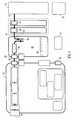
- FIG. 1shows a generalised schematic block diagram showing a general view of an apparatus and the constituent apparatus features thereof;
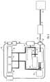
- FIG. 2shows a similar generalised schematic block diagram to FIG. 1 and showing fluid paths therein;
- FIG. 3shows a generalised schematic block diagram similar to FIG. 1 but of a device unit only and showing power paths for the various power consuming/producing features of the apparatus;
- FIG. 4shows a similar generalised schematic block diagram to FIG. 3 of the device unit and showing control system data paths for controlling the various functions and components of the apparatus;
- FIG. 5shows a perspective view of an apparatus
- FIG. 6shows a perspective view of an assembled device unit of the apparatus of FIG. 5 ;
- FIG. 7shows an exploded view of the device unit of FIG. 6 ;
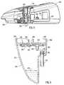
- FIG. 8shows a partially sectioned side elevation view through the interface between a waste canister and device unit of the apparatus
- FIG. 9shows a cross section through a waste canister of the apparatus of FIGS. 5 to 8 ;
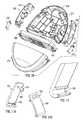
- FIG. 10shows an exploded view of casing features, waste canister parts having an embodiment according to the present invention
- FIGS. 11A and 11Bshow perspective views an inner surface of a left-hand clip and an outer surface of a right-hand clip, respectively of the embodiment shown in FIG. 10 ;
- FIG. 12shows an enlarged detail of one of the frangible clips of FIG. 11 ;
- FIG. 13shows a section through a detail of the junction portion of a device casing and waste canister with a connecting clip about to be engaged
- FIG. 14which shows a section through the same portion of device casing and waste canister as FIG. 13 from a different perspective but with the connecting clip engaged.
- FIGS. 1 to 4 of the drawingswhere the same or similar features are denoted by common reference numerals.
- FIG. 1shows a generalised schematic view of an apparatus 10 of a portable topical negative pressure (TNP) system.
- TNPtopical negative pressure
- FIG. 1shows a generalised schematic view of an apparatus 10 of a portable topical negative pressure (TNP) system.
- TNPtopical negative pressure
- FIG. 1shows a generalised schematic view of an apparatus 10 of a portable topical negative pressure (TNP) system.
- TNPtopical negative pressure
- the apparatuscomprises an aspiration conduit 12 operably and an outer surface thereof at one end sealingly attached to a dressing 14 .
- the dressing 14will not be further described here other than to say that it is formed in a known manner from well known materials to those skilled in the dressings art to create a sealed cavity over and around a wound to be treated by TNP therapy with the apparatus of the present invention.
- the aspiration conduithas an in-line connector 16 comprising connector portions 18 , 20 intermediate its length between the dressing 14 and a waste canister 22 .
- the aspiration conduit between the connector portion 20 and the canister 22is denoted by a different reference numeral 24 although the fluid path through conduit portions 12 and 24 to the waste canister is continuous.
- the connector portions 18 , 20join conduit portions 12 , 24 in a leak-free but disconnectable manner.
- the waste canister 22is provided with filters 26 which prevent the escape via an exit port 28 of liquid and bacteria from the waste canister.
- the filtersmay comprise a 1 ⁇ m hydrophobic liquid filter and a 0.2 ⁇ m bacteria filter such that all liquid and bacteria is confined to an interior waste collecting volume of the waste canister 22 .
- the exit port 28 of the waste canister 22mates with an entry/suction port 30 of a device unit 32 by means of mutually sealing connector portions 34 , 36 which engage and seal together automatically when the waste canister 22 is attached to the device unit 32 , the waste canister 22 and device unit 32 being held together by catch assemblies 38 , 40 .
- the device unit 32comprises an aspirant pump 44 , an aspirant pressure monitor 46 and an aspirant flowmeter 48 operably connected together.
- the aspiration pathtakes the aspirated fluid which in the case of fluid on the exit side of exit port 28 is gaseous through a silencer system 50 and a final filter 52 having an activated charcoal matrix which ensures that no odours escape with the gas exhausted from the device 32 via an exhaust port 54 .
- the filter 52 materialalso serves as noise reducing material to enhance the effect of the silencer system 50 .
- the device 32also contains a battery pack 56 to power the apparatus which battery pack also powers the a control system 60 which controls a user interface system 62 controlled via a keypad (not shown) and the aspiration pump 44 via signals from sensors 46 , 48 .
- a power management system 66is also provided which controls power from the battery pack 56 , the recharging thereof and the power requirements of the aspirant pump 44 and other electrically operated components.
- An electrical connector 68is provided to receive a power input jack 70 from a SELV power supply 72 connected to a mains supply 74 when the user of the apparatus or the apparatus itself is adjacent a convenient mains power socket.
- FIG. 2shows a similar schematic representation to FIG. 1 but shows the fluid paths in more detail.
- the wound exudateis aspirated from the wound site/dressing 14 via the conduit 12 , the two connector portions 18 , 20 and the conduit 24 into the waste canister 22 .
- the waste canister 22comprises a relatively large volume 80 in the region of 500 ml into which exudate from the wound is drawn by the aspiration system at an entry port 82 .
- the fluid 84 drawn into the canister volume 80is a mixture of both air drawn into the dressing 14 via the semi-permeable adhesive sealing drape (not shown) and liquid 86 in the form of wound exudates.
- the volume 80 within the canisteris also at a lowered pressure and the gaseous element 88 of the aspirated fluids is exhausted from the canister volume 80 via the filters 26 and the waste canister exhaust exit port 28 as bacteria-free gas. From the exit port 28 of the waste canister to the final exhaust port 54 the fluid is gaseous only.
- FIG. 3shows a schematic diagram showing only the device portion of the apparatus and the power paths in the device of the apparatus embodying the present invention.
- Poweris provided mainly by the battery pack 56 when the user is outside their home or workplace, for example, however, power may also be provided by an external mains 74 supplied charging unit 72 which when connected to the device 32 by the socket 68 is capable of both operating the device and recharging the battery pack 56 simultaneously.
- the power management system 66is included so as to be able to control power of the TNP system.
- the TNP systemis a rechargeable, battery powered system but is capable of being run directly from mains electricity as will be described hereinafter more fully with respect to the further figures. If disconnected from the mains the battery has enough stored charge for approximately 8 hours of use in normal conditions.
- batteries having other associated life times between rechargecan be utilised. For example batteries providing less than 8 hours or greater than 8 hours can be used.
- the deviceWhen connected to the mains the device will run off the mains power and will simultaneously recharge the battery if depleted from portable use. The exact rate of battery recharge will depend on the load on the TNP system. For example, if the wound is very large or there is a significant leak, battery recharge will take longer than if the wound is small and well sealed.
- FIG. 4shows the device 32 part of the apparatus embodying the present invention and the data paths employed in the control system for control of the aspirant pump and other features of the apparatus.
- a key purpose of the TNP systemis to apply negative pressure wound therapy. This is accomplished via the pressure control system which includes the pump and a pump control system.
- the pumpapplies negative pressure; the pressure control system gives feedback on the pressure at the pump head to the control system; the pump control varies the pump speed based on the difference between the target pressure and the actual pressure at the pump head.
- the pumpis controlled by an auxiliary control system.
- the pumpis from time to time allowed to “free-wheel” during its duty cycle by turning off the voltage applied to it.
- the spinning motorcauses a “back electro-motive force” or BEMF to be generated. This BEMF can be monitored and can be used to provide an accurate measure of pump speed. The speed can thus be adjusted more accurately than can prior art pump systems.
- actual pressure at a wound siteis not measured but the difference between a measured pressure (at the pump) and the wound pressure is minimised by the use of large filters and large bore tubes wherever practical. If the pressure control measures that the pressure at the pump head is greater than a target pressure (closer to atmospheric pressure) for a period of time, the device sends an alarm and displays a message alerting the user to a potential problem such as a leak.
- a flow metermay be positioned after the pump and is used to detect when a canister is full or the tube has become blocked. If the flow falls below a certain threshold, the device sounds an alarm and displays a message alerting a user to the potential blockage or full canister.
- FIGS. 5 to 9show various views and cross sections of a preferred embodiment of apparatus 200 embodying the present invention.
- the preferred embodimentis of generally oval shape in plan and comprises a device unit 202 and a waste canister 204 connected together by clip arrangements 206 .
- the device unit 202has a liquid crystal display (LCD) 208 , which gives text based feedback on the wound therapy being applied, and a membrane keypad 210 , the LCD being visible through the membrane of the keypad to enable a user to adjust or set the therapy to be applied to the wound (not shown).
- LCDliquid crystal display
- the devicehas a lower, generally transverse face 212 in the centre of which is a spigot 214 which forms the suction/entry port 216 to which the aspiration means (to be described below) are connected within the device unit.
- the lower edge of the device unitis provided with a rebated peripheral male mating face 218 which engages with a co-operating peripheral female formation 220 on an upper edge of the waste canister 204 (see FIGS. 8 and 9 ).
- clips 222 hinged to the canister 204have an engaging finger (not shown) which co-operates with formations in recesses 226 in the body of the device unit. From FIG.
- the casing 230 of the device unitis of largely “clamshell” construction comprising front and back mouldings 232 , 234 , respectively and left-hand and right-hand side inserts 236 , 238 .
- a central chassis 240which is fastened to an internal moulded structural member 242 and which chassis acts as a mounting for the electrical circuitry and components and also retains the battery pack (not shown) and aspiration pump unit 248 .
- Various tubing items 250 , 252 , 254connect the pump unit 248 and suction/entry port 216 to a final gaseous exhaust via a filter 290 .
- FIG. 8shows a partially sectioned side elevation of the apparatus 200 , the partial section being around the junction between the device unit 202 and the waste canister 204 , a cross section of which is shown at FIG. 9 .
- Theses viewsshow the rebated edge 218 of the male formation on the device unit co-operating with the female portion 220 defined by an upstanding flange 260 around the top face 262 of the waste canister 204 .
- the spigot 214which has an “O” ring seal 264 therearound sealingly engages with a cylindrical tube portion 266 formed around an exhaust/exit port 268 in the waste canister.
- the spigot 214 of the deviceis not rigidly fixed to the device casing but is allowed to “float” or move in its location features in the casing to permit the spigot 214 and seal 264 to move to form the best seal with the bore of the cylindrical tube portion 266 on connection of the waste canister to the device unit.
- the waste canister 204 in FIG. 9is shown in an upright orientation much as it would be when worn by a user. Thus, any exudate 270 would be in the bottom of the internal volume of waste receptacle portion 272 .
- An aspiration conduit 274is permanently affixed to an entry port spigot 278 defining an entry port 280 to receive fluid aspirated from a wound (not shown) via the conduit 274 .
- Filter members 282comprising a 0.2 ⁇ m filter and 284 comprising a 1 ⁇ m filter are located by a filter retaining member 286 adjacent a top closure member or bulkhead 288 the filter members preventing any liquid or bacteria from being drawn out of the exhaust exit port 268 into the pump and aspiration path through to an exhaust and filter unit 290 which is connected to a casing outlet member 291 via an exhaust tube (not shown) in casing side piece 236 .
- the side pieces 236 , 238are provided with recesses 292 having support pins 294 therein to locate a carrying strap (not shown) for use by the patient.
- the side pieces 230 and canister 204are also provided with features which prevent the canister and device from exhibiting a mutual “wobble” when connected together. Ribs (not shown) extending between the canister top closure member or bulkhead 288 and the inner face 300 of the upstanding flange 260 locate in grooves 302 in the device sidewalls when canister and device are connected.
- the casing 230also houses all of the electrical equipment and control and power management features, the functioning of which was described briefly with respect to FIGS. 3 and 4 hereinabove.
- the side piece 238is provided with a socket member 298 to receive a charging jack from an external mains powered battery charger (both not shown).
- FIGS. 10 to 14wherein a preferred embodiment of the present invention is shown.
- right and leftare defined as when viewing the apparatus from towards the LCD screen with the device uppermost.
- FIG. 10shows an exploded view of casing parts 230 of the device 202 and waste canister 204 : comprising the back moulding 234 , left and right-side mouldings 236 , 238 , respectively of the device; and, the waste canister receptacle portion 272 and closure bulkhead 288 .
- the waste receptacle portion 272 and the closure bulkhead 288 of the waste canisterare welded together to form a unitary canister unit.
- Connecting clip members 222are provided to connect the waste canister 204 to the device 202 .
- FIGS. 11A and 11Bshow left and right-hand clips 222 respectively and, although they are different insofar as they are handed, they both possess in principle essentially the same features of construction and function as each other.
- FIG. 11A and 11Bshow left and right-hand clips 222 respectively and, although they are different insofar as they are handed, they both possess in principle essentially the same features of construction and function as each other.
- FIG. 12shows an enlarged portion of a C-shaped feature 400 which connects the clip member 222 to the waste canister 204 by means of a snap-fit onto a shaft member 402 provided as an integral moulding on the waste canister bulkhead 288 .
- Attachment of the clip member 222 to the shaft 402is by the C-shaped feature 400 resiliently deforming slightly on pressing onto the shaft 402 before regaining its original size and providing a secure grip on the shaft 402 .
- the clip members 222also have a finger portion 404 having a downwardly directed lip portion 406 , the finger portion being resiliently deformable.
- the device side insert portions 236 , 238are each provided with a recess 408 (best seen in FIGS.
- the clip 222is able to rotate through an arc about the shaft 402 .
- a co-operating engaging feature 410which engages the finger portion 404 and the lip portion 406 .
- the engaging feature 410comprises an upstanding tooth portion 412 having a sloping lead-in portion 414 which engages with the lip portion 406 causing the finger portion 404 to resiliently deform before snapping into a locking position with a rear face 416 of the lip portion 406 in engagement with a rear face 418 of the tooth 412 so releasably connecting the device 202 and waste canister 204 together.
- the clip members 222are also provided with a tactile surface coating 430 such as a soft plastics material on their outer surface which gives a user an intuitive feel when assembling a waste canister to a device.
- the usergrips a rear face 420 of the clip member 222 above the finger member 404 and pulls in an outwardly direction with their finger.
- the engaging rear faces 416 , 418 of the lip portion 406 and tooth portion 412are both sloped such that an outwardly force causes the two surfaces 416 , 418 to slide relative to each other whilst resiliently deforming the finger portion 404 thus allowing disengagement of the clip member 222 from the device 202 and permitting removal of the waste canister.
- the engaging portion 410 on the device and engaging finger 404 on the clip membermay simply disengage due to resilient sliding of the sloped surfaces 416 , 418 allowing the device and waste canister to separate or by disengagement of the C-shaped portion 400 from the shaft portion 402 .
- the finger portion 404may snap off adjacent its root, for example, on the clip member body.
- one or both clip membersmay simply be replaced by disengaging the C-shaped portion 400 of the broken clip from the shaft portion 402 and fitting a new clip member in its place and reassembling the waste canister to the device as explained above.
Landscapes
- Health & Medical Sciences (AREA)
- Heart & Thoracic Surgery (AREA)
- Vascular Medicine (AREA)
- Engineering & Computer Science (AREA)
- Anesthesiology (AREA)
- Biomedical Technology (AREA)
- Hematology (AREA)
- Life Sciences & Earth Sciences (AREA)
- Animal Behavior & Ethology (AREA)
- General Health & Medical Sciences (AREA)
- Public Health (AREA)
- Veterinary Medicine (AREA)
- External Artificial Organs (AREA)
- Media Introduction/Drainage Providing Device (AREA)
- Surgical Instruments (AREA)
Abstract
Description
Claims (30)
Applications Claiming Priority (3)
| Application Number | Priority Date | Filing Date | Title |
|---|---|---|---|
| GBGB0712737.6AGB0712737D0 (en) | 2007-07-02 | 2007-07-02 | Apparatus |
| GB0712737.6 | 2007-07-02 | ||
| PCT/GB2008/050508WO2009004368A1 (en) | 2007-07-02 | 2008-06-27 | Modular wound treatment apparatus with releasable clip connection |
Related Parent Applications (1)
| Application Number | Title | Priority Date | Filing Date |
|---|---|---|---|
| PCT/GB2008/050508A-371-Of-InternationalWO2009004368A1 (en) | 2007-07-02 | 2008-06-27 | Modular wound treatment apparatus with releasable clip connection |
Related Child Applications (1)
| Application Number | Title | Priority Date | Filing Date |
|---|---|---|---|
| US14/141,918ContinuationUS9320838B2 (en) | 2007-07-02 | 2013-12-27 | Modular wound treatment apparatus with releasable clip connection |
Publications (2)
| Publication Number | Publication Date |
|---|---|
| US20100185164A1 US20100185164A1 (en) | 2010-07-22 |
| US8622981B2true US8622981B2 (en) | 2014-01-07 |
Family
ID=38421017
Family Applications (2)
| Application Number | Title | Priority Date | Filing Date |
|---|---|---|---|
| US12/667,227Active2030-03-25US8622981B2 (en) | 2007-07-02 | 2008-06-27 | Modular wound treatment apparatus with releasable clip connection |
| US14/141,918Active2028-12-26US9320838B2 (en) | 2007-07-02 | 2013-12-27 | Modular wound treatment apparatus with releasable clip connection |
Family Applications After (1)
| Application Number | Title | Priority Date | Filing Date |
|---|---|---|---|
| US14/141,918Active2028-12-26US9320838B2 (en) | 2007-07-02 | 2013-12-27 | Modular wound treatment apparatus with releasable clip connection |
Country Status (10)
| Country | Link |
|---|---|
| US (2) | US8622981B2 (en) |
| EP (1) | EP2162161B1 (en) |
| JP (1) | JP5274554B2 (en) |
| CN (2) | CN101730553A (en) |
| AU (1) | AU2008272679B2 (en) |
| CA (2) | CA2932001C (en) |
| GB (1) | GB0712737D0 (en) |
| MX (1) | MX2009013671A (en) |
| WO (1) | WO2009004368A1 (en) |
| ZA (1) | ZA200908654B (en) |
Cited By (46)
| Publication number | Priority date | Publication date | Assignee | Title |
|---|---|---|---|---|
| US20130066301A1 (en)* | 2011-09-13 | 2013-03-14 | Christopher Brian Locke | Reduced-pressure canisters having hydrophobic pores |
| US9205183B2 (en) | 2008-02-27 | 2015-12-08 | Smith & Nephew Plc | Fluid collection |
| US9226737B2 (en) | 2011-02-04 | 2016-01-05 | University Of Massachusetts | Negative pressure wound closure device |
| US9370450B2 (en) | 2009-02-13 | 2016-06-21 | Smith & Nephew Plc | Wound packing |
| US9421132B2 (en) | 2011-02-04 | 2016-08-23 | University Of Massachusetts | Negative pressure wound closure device |
| US9427505B2 (en) | 2012-05-15 | 2016-08-30 | Smith & Nephew Plc | Negative pressure wound therapy apparatus |
| US9526920B2 (en) | 2010-10-12 | 2016-12-27 | Smith & Nephew, Inc. | Medical device |
| US9737649B2 (en) | 2013-03-14 | 2017-08-22 | Smith & Nephew, Inc. | Systems and methods for applying reduced pressure therapy |
| US9770369B2 (en) | 2014-08-08 | 2017-09-26 | Neogenix, Llc | Wound care devices, apparatus, and treatment methods |
| US9820888B2 (en) | 2006-09-26 | 2017-11-21 | Smith & Nephew, Inc. | Wound dressing |
| US9901664B2 (en) | 2012-03-20 | 2018-02-27 | Smith & Nephew Plc | Controlling operation of a reduced pressure therapy system based on dynamic duty cycle threshold determination |
| US9956327B2 (en) | 2007-07-02 | 2018-05-01 | Smith & Nephew Plc | Wound treatment apparatus with exudate volume reduction by heat |
| US9956121B2 (en) | 2007-11-21 | 2018-05-01 | Smith & Nephew Plc | Wound dressing |
| US9962295B2 (en) | 2012-07-16 | 2018-05-08 | Smith & Nephew, Inc. | Negative pressure wound closure device |
| US9974890B2 (en) | 2008-05-21 | 2018-05-22 | Smith & Nephew, Inc. | Wound therapy system and related methods therefor |
| US10004835B2 (en) | 2008-09-05 | 2018-06-26 | Smith & Nephew, Inc. | Canister membrane for wound therapy system |
| US10070994B2 (en) | 2012-05-22 | 2018-09-11 | Smith & Nephew Plc | Apparatuses and methods for wound therapy |
| US10117782B2 (en) | 2012-05-24 | 2018-11-06 | Smith & Nephew, Inc. | Devices and methods for treating and closing wounds with negative pressure |
| US10124098B2 (en) | 2013-03-13 | 2018-11-13 | Smith & Nephew, Inc. | Negative pressure wound closure device and systems and methods of use in treating wounds with negative pressure |
| US10130526B2 (en) | 2006-09-28 | 2018-11-20 | Smith & Nephew, Inc. | Portable wound therapy system |
| US10143783B2 (en) | 2011-11-02 | 2018-12-04 | Smith & Nephew Plc | Reduced pressure therapy apparatuses and methods of using same |
| US10155070B2 (en) | 2013-08-13 | 2018-12-18 | Smith & Nephew, Inc. | Systems and methods for applying reduced pressure therapy |
| US10159771B2 (en) | 2013-03-14 | 2018-12-25 | Smith & Nephew Plc | Compressible wound fillers and systems and methods of use in treating wounds with negative pressure |
| US10307517B2 (en) | 2010-09-20 | 2019-06-04 | Smith & Nephew Plc | Systems and methods for controlling operation of a reduced pressure therapy system |
| US10328187B2 (en) | 2007-07-02 | 2019-06-25 | Smith & Nephew Plc | Systems and methods for controlling operation of negative pressure wound therapy apparatus |
| US10328188B2 (en) | 2013-03-14 | 2019-06-25 | Smith & Nephew, Inc. | Systems and methods for applying reduced pressure therapy |
| US10549016B2 (en) | 2014-12-30 | 2020-02-04 | Smith & Nephew, Inc. | Blockage detection in reduced pressure therapy |
| WO2020038822A1 (en) | 2018-08-21 | 2020-02-27 | T.J.Smith And Nephew,Limited | Negative pressure wound therapy device status indication using a canister |
| US10575991B2 (en) | 2015-12-15 | 2020-03-03 | University Of Massachusetts | Negative pressure wound closure devices and methods |
| US10617801B2 (en) | 2007-08-06 | 2020-04-14 | Smith & Nephew Plc | Canister status determination |
| US10682446B2 (en) | 2014-12-22 | 2020-06-16 | Smith & Nephew Plc | Dressing status detection for negative pressure wound therapy |
| US10702420B2 (en) | 2012-05-22 | 2020-07-07 | Smith & Nephew Plc | Wound closure device |
| US10709826B2 (en) | 2006-10-13 | 2020-07-14 | Smith & Nephew, Inc. | Control circuit and method for negative pressure wound treatment apparatus |
| US10737000B2 (en) | 2008-08-21 | 2020-08-11 | Smith & Nephew, Inc. | Sensor with electrical contact protection for use in fluid collection canister and negative pressure wound therapy systems including same |
| US10744239B2 (en) | 2014-07-31 | 2020-08-18 | Smith & Nephew, Inc. | Leak detection in negative pressure wound therapy system |
| US10814049B2 (en) | 2015-12-15 | 2020-10-27 | University Of Massachusetts | Negative pressure wound closure devices and methods |
| US10912869B2 (en) | 2008-05-21 | 2021-02-09 | Smith & Nephew, Inc. | Wound therapy system with related methods therefor |
| US11357906B2 (en) | 2016-02-12 | 2022-06-14 | Smith & Nephew, Inc. | Systems and methods for detecting operational conditions of reduced pressure therapy |
| US11439539B2 (en) | 2015-04-29 | 2022-09-13 | University Of Massachusetts | Negative pressure wound closure device |
| US11471586B2 (en) | 2015-12-15 | 2022-10-18 | University Of Massachusetts | Negative pressure wound closure devices and methods |
| US11602461B2 (en) | 2016-05-13 | 2023-03-14 | Smith & Nephew, Inc. | Automatic wound coupling detection in negative pressure wound therapy systems |
| US12029549B2 (en) | 2007-12-06 | 2024-07-09 | Smith & Nephew Plc | Apparatus and method for wound volume measurement |
| US12097095B2 (en) | 2011-05-26 | 2024-09-24 | Smith & Nephew, Inc. | Method and apparatus for providing negative pressure to a negative pressure wound therapy bandage |
| US12121648B2 (en) | 2007-08-06 | 2024-10-22 | Smith & Nephew Plc | Canister status determination |
| US12133790B2 (en) | 2013-10-21 | 2024-11-05 | Smith & Nephew, Inc. | Negative pressure wound closure device |
| US12133789B2 (en) | 2014-07-31 | 2024-11-05 | Smith & Nephew, Inc. | Reduced pressure therapy apparatus construction and control |
Families Citing this family (65)
| Publication number | Priority date | Publication date | Assignee | Title |
|---|---|---|---|---|
| GB0715211D0 (en)* | 2007-08-06 | 2007-09-12 | Smith & Nephew | Apparatus |
| GB0715212D0 (en)* | 2007-08-06 | 2007-09-12 | Smith & Nephew | Apparatus |
| US8007481B2 (en) | 2008-07-17 | 2011-08-30 | Tyco Healthcare Group Lp | Subatmospheric pressure mechanism for wound therapy system |
| SE533726C2 (en) | 2009-04-30 | 2010-12-14 | Moelnlycke Health Care Ab | Apparatus with negative pressure for treatment of wounds |
| US20100318071A1 (en)* | 2009-06-10 | 2010-12-16 | Tyco Healthcare Group Lp | Fluid Collection Canister Including Canister Top with Filter Membrane and Negative Pressure Wound Therapy Systems Including Same |
| DE102009038130A1 (en) | 2009-08-12 | 2011-02-17 | ATMOS Medizin Technik GmbH & Co. KG | A user portable device for providing negative pressure for medical applications |
| DE102009038131A1 (en)* | 2009-08-12 | 2011-02-17 | ATMOS Medizin Technik GmbH & Co. KG | A user portable device for providing negative pressure for medical applications |
| AU2010298770B2 (en) | 2009-09-22 | 2015-05-28 | Molnlycke Health Care Ab | An apparatus and method for controlling the negative pressure in a wound |
| IT1398683B1 (en)* | 2010-03-05 | 2013-03-08 | Ergon Sutramed S P A | PULMONARY DRAINAGE SYSTEM. |
| US10207031B2 (en) | 2010-12-08 | 2019-02-19 | Convatec Technologies Inc. | Integrated system for assessing wound exudates |
| ES2748519T3 (en) | 2010-12-08 | 2020-03-17 | Convatec Technologies Inc | Wound exudate system accessory |
| ES2672230T3 (en) | 2011-11-02 | 2018-06-13 | Smith & Nephew Plc | Reduced pressure therapy devices |
| DE102012008301A1 (en)* | 2012-04-26 | 2013-10-31 | Paul Hartmann Ag | Fastening device for a negative pressure therapy device |
| AU2014290371B2 (en) | 2013-07-19 | 2019-03-07 | Atrium Medical Corporation | Chest drainage systems and methods |
| DE102013226713A1 (en)* | 2013-12-19 | 2015-06-25 | Paul Hartmann Ag | System for combined vacuum and instillation treatment of wounds |
| US10226376B2 (en) | 2014-03-19 | 2019-03-12 | Purewick Corporation | Apparatus and methods for receiving discharged urine |
| US10952889B2 (en) | 2016-06-02 | 2021-03-23 | Purewick Corporation | Using wicking material to collect liquid for transport |
| US11090183B2 (en) | 2014-11-25 | 2021-08-17 | Purewick Corporation | Container for collecting liquid for transport |
| US11376152B2 (en) | 2014-03-19 | 2022-07-05 | Purewick Corporation | Apparatus and methods for receiving discharged urine |
| US10390989B2 (en) | 2014-03-19 | 2019-08-27 | Purewick Corporation | Apparatus and methods for receiving discharged urine |
| US11806266B2 (en) | 2014-03-19 | 2023-11-07 | Purewick Corporation | Apparatus and methods for receiving discharged urine |
| CN104225769B (en)* | 2014-09-30 | 2017-07-14 | 昆山韦睿医疗科技有限公司 | Negative pressure treatment systems, the first negative pressure treatment equipment and the second negative pressure treatment equipment |
| CN104667360B (en)* | 2015-02-11 | 2017-07-14 | 昆山韦睿医疗科技有限公司 | A kind of negative pressure wound therapy device |
| US10376406B2 (en) | 2016-07-27 | 2019-08-13 | Purewick Corporation | Male urine collection device using wicking material |
| US10973678B2 (en) | 2016-07-27 | 2021-04-13 | Purewick Corporation | Apparatus and methods for receiving discharged urine |
| JP2020510464A (en) | 2017-01-31 | 2020-04-09 | ピュアウィック コーポレイション | Apparatus and method for receiving excreted urine |
| WO2018195101A1 (en) | 2017-04-19 | 2018-10-25 | Smith & Nephew, Inc. | Negative pressure wound therapy canisters |
| US20200368403A1 (en)* | 2017-10-23 | 2020-11-26 | Kci Licensing, Inc. | Systems and methods for high-strength canister retention with automated, non-mechanical canister release for use with medical fluid collection systems |
| US10624794B2 (en) | 2018-02-12 | 2020-04-21 | Healyx Labs, Inc. | Negative pressure wound therapy systems, devices, and methods |
| EP3773385B1 (en)* | 2018-03-26 | 2025-02-12 | DeRoyal Industries, Inc. | Multi-lumen bridge for negative pressure wound therapy system |
| WO2019212950A1 (en) | 2018-05-01 | 2019-11-07 | Purewick Corporation | Fluid collection devices, related systems, and related methods |
| KR102492111B1 (en) | 2018-05-01 | 2023-01-27 | 퓨어윅 코포레이션 | Fluid Collection Devices and Methods of Using The Same |
| KR102513810B1 (en) | 2018-05-01 | 2023-03-24 | 퓨어윅 코포레이션 | Fluid collection devices, systems and methods |
| JP7093851B2 (en) | 2018-05-01 | 2022-06-30 | ピュアウィック コーポレイション | Fluid collecting clothing |
| WO2019212952A1 (en) | 2018-05-01 | 2019-11-07 | Purewick Corporation | Fluid collection devices, related systems, and related methods |
| EP3666301B1 (en)* | 2018-12-14 | 2024-02-21 | Mölnlycke Health Care AB | A canister for a mobile negative pressure wound therapy device |
| WO2020256865A1 (en) | 2019-06-21 | 2020-12-24 | Purewick Corporation | Fluid collection devices including a base securement area, and related systems and methods |
| CN110353891B (en)* | 2019-07-19 | 2021-07-30 | 四川大学华西医院 | An applicator for transparent applicator |
| US12329364B2 (en) | 2019-07-19 | 2025-06-17 | Purewick Corporation | Fluid collection devices including at least one shape memory material |
| GB201914283D0 (en) | 2019-10-03 | 2019-11-20 | Smith & Nephew | Apparatuses and methods for negative pressure wound therapy |
| US12350190B2 (en) | 2020-01-03 | 2025-07-08 | Purewick Corporation | Urine collection devices having a relatively wide portion and an elongated portion and related methods |
| US11890407B2 (en)* | 2020-03-05 | 2024-02-06 | Deroyal Industries, Inc. | Negative pressure wound therapy canister connection system |
| ES2969642T3 (en) | 2020-04-10 | 2024-05-21 | Purewick Corp | Fluid collection assemblies that include one or more leak prevention features |
| US12048643B2 (en) | 2020-05-27 | 2024-07-30 | Purewick Corporation | Fluid collection assemblies including at least one inflation device and methods and systems of using the same |
| USD967409S1 (en) | 2020-07-15 | 2022-10-18 | Purewick Corporation | Urine collection apparatus cover |
| US20220047410A1 (en) | 2020-08-11 | 2022-02-17 | Purewick Corporation | Fluid collection assemblies defining waist and leg openings |
| US11801186B2 (en) | 2020-09-10 | 2023-10-31 | Purewick Corporation | Urine storage container handle and lid accessories |
| US12156792B2 (en) | 2020-09-10 | 2024-12-03 | Purewick Corporation | Fluid collection assemblies including at least one inflation device |
| US12042423B2 (en) | 2020-10-07 | 2024-07-23 | Purewick Corporation | Fluid collection systems including at least one tensioning element |
| US12208031B2 (en) | 2020-10-21 | 2025-01-28 | Purewick Corporation | Adapters for fluid collection devices |
| US12257174B2 (en) | 2020-10-21 | 2025-03-25 | Purewick Corporation | Fluid collection assemblies including at least one of a protrusion or at least one expandable material |
| US12048644B2 (en) | 2020-11-03 | 2024-07-30 | Purewick Corporation | Apparatus for receiving discharged urine |
| US12070432B2 (en) | 2020-11-11 | 2024-08-27 | Purewick Corporation | Urine collection system including a flow meter and related methods |
| US12245967B2 (en) | 2020-11-18 | 2025-03-11 | Purewick Corporation | Fluid collection assemblies including an adjustable spine |
| US12268627B2 (en) | 2021-01-06 | 2025-04-08 | Purewick Corporation | Fluid collection assemblies including at least one securement body |
| CA3162613A1 (en) | 2021-01-19 | 2022-07-19 | Purewick Corporation | Variable fit fluid collection devices, systems, and methods |
| US12178735B2 (en) | 2021-02-09 | 2024-12-31 | Purewick Corporation | Noise reduction for a urine suction system |
| EP4274524B1 (en) | 2021-02-26 | 2024-08-28 | Purewick Corporation | A male fluid collection device configured as a male urine collection device |
| US11938054B2 (en) | 2021-03-10 | 2024-03-26 | Purewick Corporation | Bodily waste and fluid collection with sacral pad |
| US12029677B2 (en) | 2021-04-06 | 2024-07-09 | Purewick Corporation | Fluid collection devices having a collection bag, and related systems and methods |
| US12233003B2 (en) | 2021-04-29 | 2025-02-25 | Purewick Corporation | Fluid collection assemblies including at least one length adjusting feature |
| US12251333B2 (en) | 2021-05-21 | 2025-03-18 | Purewick Corporation | Fluid collection assemblies including at least one inflation device and methods and systems of using the same |
| US12324767B2 (en) | 2021-05-24 | 2025-06-10 | Purewick Corporation | Fluid collection assembly including a customizable external support and related methods |
| US12150885B2 (en) | 2021-05-26 | 2024-11-26 | Purewick Corporation | Fluid collection system including a cleaning system and methods |
| US20250090743A1 (en)* | 2023-09-14 | 2025-03-20 | Deroyal Industries, Inc | Canister connection system for disposable negative pressure wound therapy system |
Citations (70)
| Publication number | Priority date | Publication date | Assignee | Title |
|---|---|---|---|---|
| DE1000684B (en) | 1952-03-20 | 1957-01-10 | Zeiss Ikon Ag | Ready-to-use pouch for cameras with zipper and hanging device |
| US3295576A (en) | 1963-10-23 | 1967-01-03 | Eastman Kodak Co | Carrying case, particularly for photographic cameras |
| US4112949A (en) | 1976-11-15 | 1978-09-12 | Howmedica Inc. | Apparatus for collecting body fluid |
| US4250882A (en) | 1979-01-26 | 1981-02-17 | Medical Dynamics, Inc. | Wound drainage device |
| DE3431426A1 (en) | 1984-01-04 | 1985-07-18 | Ernst A. F. Dr. 5000 Köln Schmidt | Ever-ready bag particularly suitable for reflex cameras |
| US4569674A (en) | 1982-08-03 | 1986-02-11 | Stryker Corporation | Continuous vacuum wound drainage system |
| US4758220A (en) | 1985-09-26 | 1988-07-19 | Alcon Laboratories, Inc. | Surgical cassette proximity sensing and latching apparatus |
| US4969880A (en) | 1989-04-03 | 1990-11-13 | Zamierowski David S | Wound dressing and treatment method |
| JPH0311106A (en) | 1989-05-24 | 1991-01-18 | Florida Inst Of Phosphate Res | Coal mon-fuel combustion thermal power plant having contamination preventing system and producing useful byproduct |
| US5096385A (en) | 1989-11-08 | 1992-03-17 | Ivac Corporation | Method and system for upstream occlusion detection |
| WO1992010983A1 (en) | 1990-12-24 | 1992-07-09 | Arthur Michael Newsam Gardner | Bandage |
| JPH0658150A (en) | 1992-06-17 | 1994-03-01 | Ricardo Consulting Eng Plc | Diesel engine |
| JPH06339495A (en) | 1993-01-22 | 1994-12-13 | Taiichiro Iwakura | Expansible tape for medical aid |
| US5466229A (en)* | 1993-08-06 | 1995-11-14 | Davstar, Inc. | Fluid collection system |
| WO1996005873A1 (en)* | 1994-08-22 | 1996-02-29 | Kinetic Concepts Inc. | Wound drainage equipment |
| WO1996005878A1 (en) | 1994-08-24 | 1996-02-29 | Eli Lilly Japan Kabushiki Kaisha | Injection apparatus |
| US5527293A (en) | 1989-04-03 | 1996-06-18 | Kinetic Concepts, Inc. | Fastening system and method |
| JPH08320006A (en) | 1995-05-26 | 1996-12-03 | B C Seisakusho:Kk | Clamping device of air cleaner |
| US5636643A (en) | 1991-11-14 | 1997-06-10 | Wake Forest University | Wound treatment employing reduced pressure |
| US5645081A (en) | 1991-11-14 | 1997-07-08 | Wake Forest University | Method of treating tissue damage and apparatus for same |
| US5738656A (en) | 1993-03-02 | 1998-04-14 | Wagner; Wolfgang | Drainage apparatus and method of use |
| US6071267A (en) | 1998-02-06 | 2000-06-06 | Kinetic Concepts, Inc. | Medical patient fluid management interface system and method |
| GB2336546B (en) | 1995-11-14 | 2000-06-14 | Kci Medical Ltd | Apparatus for applying negative pressure to a wound |
| US6117111A (en) | 1994-09-20 | 2000-09-12 | Fleischmann; Wim | Device for sealing an injury area |
| US6345623B1 (en) | 1997-09-12 | 2002-02-12 | Keith Patrick Heaton | Surgical drape and suction head for wound treatment |
| US20030163101A1 (en) | 2002-02-28 | 2003-08-28 | Say Samuel L. | Portable battery operated aspirator |
| US6648862B2 (en) | 2001-11-20 | 2003-11-18 | Spheric Products, Ltd. | Personally portable vacuum desiccator |
| US6685681B2 (en) | 2000-11-29 | 2004-02-03 | Hill-Rom Services, Inc. | Vacuum therapy and cleansing dressing for wounds |
| US6764462B2 (en) | 2000-11-29 | 2004-07-20 | Hill-Rom Services Inc. | Wound treatment apparatus |
| US6824533B2 (en) | 2000-11-29 | 2004-11-30 | Hill-Rom Services, Inc. | Wound treatment apparatus |
| US6936037B2 (en) | 2002-12-31 | 2005-08-30 | Kci Licensing, Inc. | Tissue closure treatment system, patient interface and method |
| US7004915B2 (en) | 2001-08-24 | 2006-02-28 | Kci Licensing, Inc. | Negative pressure assisted tissue treatment system |
| US7022113B2 (en) | 2001-07-12 | 2006-04-04 | Hill-Rom Services, Inc. | Control of vacuum level rate of change |
| US7108683B2 (en) | 2001-04-30 | 2006-09-19 | Kci Licensing, Inc | Wound therapy and tissue management system and method with fluid differentiation |
| WO2006105892A1 (en) | 2005-04-06 | 2006-10-12 | Inmeditec Medizintechnik Gmbh | Tube connector for a vacuum therapy device |
| WO2006135934A2 (en) | 2005-06-13 | 2006-12-21 | Smith & Nephew, Inc. | Surgical fluid management |
| WO2007013064A1 (en) | 2005-07-24 | 2007-02-01 | Carmeli Adahan | Suctioning system, method and kit |
| WO2007024230A1 (en) | 2005-08-26 | 2007-03-01 | Spheric Products, Ltd. | Chest tube drainage system |
| EP1171065B1 (en) | 1999-04-22 | 2007-03-14 | KCI Licensing, Inc. | Wound treatment apparatus employing reduced pressure |
| WO2007030599A2 (en) | 2005-09-07 | 2007-03-15 | Tyco Healthcare Group Lp | Self contained wound dressing apparatus |
| US7195624B2 (en) | 2001-12-26 | 2007-03-27 | Hill-Rom Services, Inc. | Vented vacuum bandage with irrigation for wound healing and method |
| US7198046B1 (en) | 1991-11-14 | 2007-04-03 | Wake Forest University Health Sciences | Wound treatment employing reduced pressure |
| US20070179460A1 (en) | 2006-02-01 | 2007-08-02 | Carmeli Adahan | Suctioning system, method and kit |
| WO2007087808A1 (en) | 2006-02-02 | 2007-08-09 | Coloplast A/S | Pump and system for treatment of a wound |
| US20070219532A1 (en) | 2005-07-14 | 2007-09-20 | Boehringer Technologies, Lp | Pump system for negative pressure wound therapy |
| US20070292276A1 (en) | 2004-09-20 | 2007-12-20 | Medela Holding Ag | Membrane Pump with Bleed Valve |
| WO2008039314A2 (en) | 2006-09-26 | 2008-04-03 | Boehringer Technologies, Lp | Pump system for negative pressure wound therapy |
| US7381859B2 (en) | 2000-05-09 | 2008-06-03 | Kci Licensing, Inc. | Removable wound closure |
| US7438705B2 (en) | 2005-07-14 | 2008-10-21 | Boehringer Technologies, L.P. | System for treating a wound with suction and method detecting loss of suction |
| USD587901S1 (en) | 2007-07-02 | 2009-03-10 | Smith & Nephew Plc | Bag |
| US7534927B2 (en) | 2001-12-26 | 2009-05-19 | Hill-Rom Services, Inc. | Vacuum bandage packing |
| US7553306B1 (en) | 1998-10-13 | 2009-06-30 | Kci Licensing, Inc. | Negative pressure therapy using wall suction |
| US20090240218A1 (en) | 2008-03-20 | 2009-09-24 | Tyco Healthcare Group Lp | Wound Therapy System |
| USD602584S1 (en) | 2007-07-02 | 2009-10-20 | Smith & Nephew Plc | Canister |
| USD602582S1 (en) | 2007-07-02 | 2009-10-20 | Smith & Nephew LLC | Therapy unit assembly |
| USD602583S1 (en) | 2007-07-02 | 2009-10-20 | Smith & Nephew Plc | Device for applying negative pressure to a wound |
| USD607202S1 (en) | 2007-12-28 | 2010-01-05 | Smith & Nephew Plc | Double flap bag |
| US20100042021A1 (en) | 2008-02-14 | 2010-02-18 | Spiracur, Inc. | Devices and methods for treatment of damaged tissue |
| US20100106116A1 (en) | 2008-10-29 | 2010-04-29 | Tyler Simmons | Medical canister connectors |
| US20100185165A1 (en) | 2007-07-02 | 2010-07-22 | Max Middleton | Silencer for vacuum system of a wound drainage apparatus |
| US20100187065A1 (en) | 2007-07-02 | 2010-07-29 | Andrew Pidgeon | Carrying Bag |
| US20100207768A1 (en) | 2007-07-02 | 2010-08-19 | Smith & Nephew Plc | Topical negative pressure system with status indication |
| US7780201B2 (en) | 2006-10-13 | 2010-08-24 | Medela Holding Ag | Tube connector with three part construction and latching component |
| US20100228205A1 (en) | 2009-03-04 | 2010-09-09 | Spiracur Inc. | Devices and methods to apply alternating level of reduced pressure to tissue |
| US20100244780A1 (en) | 2007-07-02 | 2010-09-30 | Jake Turner | Battery Recharging |
| US7846141B2 (en) | 2002-09-03 | 2010-12-07 | Bluesky Medical Group Incorporated | Reduced pressure treatment system |
| US20110008179A1 (en) | 2007-07-02 | 2011-01-13 | Smith & Nephew Plc | Pressure control |
| US20110054810A1 (en) | 2007-08-06 | 2011-03-03 | Smith & Nephew Plc | Determining pressure |
| USD645137S1 (en) | 2009-12-04 | 2011-09-13 | Smith & Nephew Plc | Canister |
| US20120001762A1 (en) | 2007-08-06 | 2012-01-05 | Smith & Nephew Plc | Determining flow rate |
Family Cites Families (7)
| Publication number | Priority date | Publication date | Assignee | Title |
|---|---|---|---|---|
| JPS614699Y2 (en)* | 1980-08-14 | 1986-02-13 | ||
| JPS5742157A (en) | 1980-08-26 | 1982-03-09 | Citizen Watch Co Ltd | Formation of pattern for circuit substrate |
| JPH0736172Y2 (en)* | 1989-06-20 | 1995-08-16 | 坂本工業株式会社 | Clamp device |
| JP2510680Y2 (en)* | 1993-01-21 | 1996-09-18 | 東洋▲ろ▼機製造株式会社 | Clamp mechanism |
| GB0224986D0 (en) | 2002-10-28 | 2002-12-04 | Smith & Nephew | Apparatus |
| US7011364B2 (en) | 2003-07-09 | 2006-03-14 | J.F. Meskill Enterprises, L.L.C. | Table with folding legs |
| KR20090126259A (en)* | 2007-02-14 | 2009-12-08 | 멤피스 컴퍼니 리미티드 | Sports shoes |
- 2007
- 2007-07-02GBGBGB0712737.6Apatent/GB0712737D0/ennot_activeCeased
- 2008
- 2008-06-27MXMX2009013671Apatent/MX2009013671A/ennot_activeApplication Discontinuation
- 2008-06-27AUAU2008272679Apatent/AU2008272679B2/enactiveActive
- 2008-06-27CACA2932001Apatent/CA2932001C/ennot_activeExpired - Fee Related
- 2008-06-27CACA2691697Apatent/CA2691697C/enactiveActive
- 2008-06-27USUS12/667,227patent/US8622981B2/enactiveActive
- 2008-06-27CNCN200880023343Apatent/CN101730553A/enactivePending
- 2008-06-27WOPCT/GB2008/050508patent/WO2009004368A1/enactiveApplication Filing
- 2008-06-27JPJP2010514139Apatent/JP5274554B2/enactiveActive
- 2008-06-27CNCN201510654910.6Apatent/CN105214202B/enactiveActive
- 2008-06-27EPEP08762610.7Apatent/EP2162161B1/enactiveActive
- 2009
- 2009-12-04ZAZA200908654Apatent/ZA200908654B/enunknown
- 2013
- 2013-12-27USUS14/141,918patent/US9320838B2/enactiveActive
Patent Citations (93)
| Publication number | Priority date | Publication date | Assignee | Title |
|---|---|---|---|---|
| DE1000684B (en) | 1952-03-20 | 1957-01-10 | Zeiss Ikon Ag | Ready-to-use pouch for cameras with zipper and hanging device |
| US3295576A (en) | 1963-10-23 | 1967-01-03 | Eastman Kodak Co | Carrying case, particularly for photographic cameras |
| US4112949A (en) | 1976-11-15 | 1978-09-12 | Howmedica Inc. | Apparatus for collecting body fluid |
| US4250882A (en) | 1979-01-26 | 1981-02-17 | Medical Dynamics, Inc. | Wound drainage device |
| US4569674A (en) | 1982-08-03 | 1986-02-11 | Stryker Corporation | Continuous vacuum wound drainage system |
| DE3431426A1 (en) | 1984-01-04 | 1985-07-18 | Ernst A. F. Dr. 5000 Köln Schmidt | Ever-ready bag particularly suitable for reflex cameras |
| US4758220A (en) | 1985-09-26 | 1988-07-19 | Alcon Laboratories, Inc. | Surgical cassette proximity sensing and latching apparatus |
| US4969880A (en) | 1989-04-03 | 1990-11-13 | Zamierowski David S | Wound dressing and treatment method |
| US5527293A (en) | 1989-04-03 | 1996-06-18 | Kinetic Concepts, Inc. | Fastening system and method |
| JPH0311106A (en) | 1989-05-24 | 1991-01-18 | Florida Inst Of Phosphate Res | Coal mon-fuel combustion thermal power plant having contamination preventing system and producing useful byproduct |
| US5096385A (en) | 1989-11-08 | 1992-03-17 | Ivac Corporation | Method and system for upstream occlusion detection |
| WO1992010983A1 (en) | 1990-12-24 | 1992-07-09 | Arthur Michael Newsam Gardner | Bandage |
| US7216651B2 (en) | 1991-11-14 | 2007-05-15 | Wake Forest University Health Sciences | Wound treatment employing reduced pressure |
| US7198046B1 (en) | 1991-11-14 | 2007-04-03 | Wake Forest University Health Sciences | Wound treatment employing reduced pressure |
| US5636643A (en) | 1991-11-14 | 1997-06-10 | Wake Forest University | Wound treatment employing reduced pressure |
| US5645081A (en) | 1991-11-14 | 1997-07-08 | Wake Forest University | Method of treating tissue damage and apparatus for same |
| JPH0658150A (en) | 1992-06-17 | 1994-03-01 | Ricardo Consulting Eng Plc | Diesel engine |
| JPH06339495A (en) | 1993-01-22 | 1994-12-13 | Taiichiro Iwakura | Expansible tape for medical aid |
| US5738656A (en) | 1993-03-02 | 1998-04-14 | Wagner; Wolfgang | Drainage apparatus and method of use |
| EP0688189B2 (en) | 1993-03-09 | 2005-06-01 | Wake Forest University | Wound treatment employing reduced pressure |
| EP0688189B1 (en) | 1993-03-09 | 2000-09-13 | Wake Forest University | Wound treatment employing reduced pressure |
| US5466229A (en)* | 1993-08-06 | 1995-11-14 | Davstar, Inc. | Fluid collection system |
| EP0777504A1 (en) | 1994-08-22 | 1997-06-11 | Kinetic Concepts, Inc. | Wound drainage equipment |
| EP0853950A1 (en) | 1994-08-22 | 1998-07-22 | Kinetic Concepts, Inc. | Wound drainage canister |
| WO1996005873A1 (en)* | 1994-08-22 | 1996-02-29 | Kinetic Concepts Inc. | Wound drainage equipment |
| US7611500B1 (en) | 1994-08-22 | 2009-11-03 | Kci Licensing, Inc. | Wound therapy device and related methods |
| EP1219311A2 (en) | 1994-08-22 | 2002-07-03 | Kinetic Concepts, Inc. | Canister |
| WO1996005878A1 (en) | 1994-08-24 | 1996-02-29 | Eli Lilly Japan Kabushiki Kaisha | Injection apparatus |
| US6117111A (en) | 1994-09-20 | 2000-09-12 | Fleischmann; Wim | Device for sealing an injury area |
| JPH08320006A (en) | 1995-05-26 | 1996-12-03 | B C Seisakusho:Kk | Clamping device of air cleaner |
| GB2336546B (en) | 1995-11-14 | 2000-06-14 | Kci Medical Ltd | Apparatus for applying negative pressure to a wound |
| US6142982A (en) | 1995-11-14 | 2000-11-07 | Kci Medical Limited | Portable wound treatment apparatus |
| EP1440667B1 (en) | 1997-09-12 | 2006-03-01 | KCI Licensing, Inc. | Surgical drape |
| US6345623B1 (en) | 1997-09-12 | 2002-02-12 | Keith Patrick Heaton | Surgical drape and suction head for wound treatment |
| US6071267A (en) | 1998-02-06 | 2000-06-06 | Kinetic Concepts, Inc. | Medical patient fluid management interface system and method |
| US7553306B1 (en) | 1998-10-13 | 2009-06-30 | Kci Licensing, Inc. | Negative pressure therapy using wall suction |
| EP1171065B1 (en) | 1999-04-22 | 2007-03-14 | KCI Licensing, Inc. | Wound treatment apparatus employing reduced pressure |
| US7763000B2 (en) | 1999-11-29 | 2010-07-27 | Risk Jr James R | Wound treatment apparatus having a display |
| US20040249353A1 (en) | 1999-11-29 | 2004-12-09 | Risks James R. | Wound treatment apparatus |
| US7381859B2 (en) | 2000-05-09 | 2008-06-03 | Kci Licensing, Inc. | Removable wound closure |
| US6764462B2 (en) | 2000-11-29 | 2004-07-20 | Hill-Rom Services Inc. | Wound treatment apparatus |
| US6824533B2 (en) | 2000-11-29 | 2004-11-30 | Hill-Rom Services, Inc. | Wound treatment apparatus |
| US6752794B2 (en) | 2000-11-29 | 2004-06-22 | Hill-Rom Services, Inc. | Vacuum therapy and cleansing dressing for wounds |
| US6685681B2 (en) | 2000-11-29 | 2004-02-03 | Hill-Rom Services, Inc. | Vacuum therapy and cleansing dressing for wounds |
| US7108683B2 (en) | 2001-04-30 | 2006-09-19 | Kci Licensing, Inc | Wound therapy and tissue management system and method with fluid differentiation |
| US7022113B2 (en) | 2001-07-12 | 2006-04-04 | Hill-Rom Services, Inc. | Control of vacuum level rate of change |
| US7004915B2 (en) | 2001-08-24 | 2006-02-28 | Kci Licensing, Inc. | Negative pressure assisted tissue treatment system |
| US6648862B2 (en) | 2001-11-20 | 2003-11-18 | Spheric Products, Ltd. | Personally portable vacuum desiccator |
| US7534927B2 (en) | 2001-12-26 | 2009-05-19 | Hill-Rom Services, Inc. | Vacuum bandage packing |
| US7195624B2 (en) | 2001-12-26 | 2007-03-27 | Hill-Rom Services, Inc. | Vented vacuum bandage with irrigation for wound healing and method |
| US20030163101A1 (en) | 2002-02-28 | 2003-08-28 | Say Samuel L. | Portable battery operated aspirator |
| WO2003074106A2 (en) | 2002-02-28 | 2003-09-12 | Say Samuel L | Portable battery operated aspirator |
| US7846141B2 (en) | 2002-09-03 | 2010-12-07 | Bluesky Medical Group Incorporated | Reduced pressure treatment system |
| US6936037B2 (en) | 2002-12-31 | 2005-08-30 | Kci Licensing, Inc. | Tissue closure treatment system, patient interface and method |
| US20070292276A1 (en) | 2004-09-20 | 2007-12-20 | Medela Holding Ag | Membrane Pump with Bleed Valve |
| US20100063464A1 (en) | 2005-04-06 | 2010-03-11 | Johannes Meyer | Tube Connector for a Vacuum Therapy Device |
| WO2006105892A1 (en) | 2005-04-06 | 2006-10-12 | Inmeditec Medizintechnik Gmbh | Tube connector for a vacuum therapy device |
| WO2006135934A2 (en) | 2005-06-13 | 2006-12-21 | Smith & Nephew, Inc. | Surgical fluid management |
| US7604610B2 (en) | 2005-06-13 | 2009-10-20 | Smith & Nephew, Inc. | Surgical fluid management |
| US20070219532A1 (en) | 2005-07-14 | 2007-09-20 | Boehringer Technologies, Lp | Pump system for negative pressure wound therapy |
| US7438705B2 (en) | 2005-07-14 | 2008-10-21 | Boehringer Technologies, L.P. | System for treating a wound with suction and method detecting loss of suction |
| WO2007013064A1 (en) | 2005-07-24 | 2007-02-01 | Carmeli Adahan | Suctioning system, method and kit |
| US20090157016A1 (en) | 2005-07-24 | 2009-06-18 | Carmeli Adahan | Suctioning system, method and kit |
| WO2007024230A1 (en) | 2005-08-26 | 2007-03-01 | Spheric Products, Ltd. | Chest tube drainage system |
| WO2007030599A2 (en) | 2005-09-07 | 2007-03-15 | Tyco Healthcare Group Lp | Self contained wound dressing apparatus |
| US20070179460A1 (en) | 2006-02-01 | 2007-08-02 | Carmeli Adahan | Suctioning system, method and kit |
| WO2007087808A1 (en) | 2006-02-02 | 2007-08-09 | Coloplast A/S | Pump and system for treatment of a wound |
| WO2008039223A1 (en) | 2006-09-26 | 2008-04-03 | Boehringer Technologies L.P. | Pump system for negative pressure wound therapy |
| WO2008039314A2 (en) | 2006-09-26 | 2008-04-03 | Boehringer Technologies, Lp | Pump system for negative pressure wound therapy |
| US7780201B2 (en) | 2006-10-13 | 2010-08-24 | Medela Holding Ag | Tube connector with three part construction and latching component |
| US20100244780A1 (en) | 2007-07-02 | 2010-09-30 | Jake Turner | Battery Recharging |
| USD630313S1 (en) | 2007-07-02 | 2011-01-04 | Smith & Nephew Plc | Therapy unit assembly |
| US20110008179A1 (en) | 2007-07-02 | 2011-01-13 | Smith & Nephew Plc | Pressure control |
| USD602583S1 (en) | 2007-07-02 | 2009-10-20 | Smith & Nephew Plc | Device for applying negative pressure to a wound |
| USD630725S1 (en) | 2007-07-02 | 2011-01-11 | Smith & Nephew Plc | Canister |
| USD625801S1 (en) | 2007-07-02 | 2010-10-19 | Smith & Nephew Plc | Device for applying negative pressure to a wound |
| USD587901S1 (en) | 2007-07-02 | 2009-03-10 | Smith & Nephew Plc | Bag |
| US20100185165A1 (en) | 2007-07-02 | 2010-07-22 | Max Middleton | Silencer for vacuum system of a wound drainage apparatus |
| USD602582S1 (en) | 2007-07-02 | 2009-10-20 | Smith & Nephew LLC | Therapy unit assembly |
| US20100187065A1 (en) | 2007-07-02 | 2010-07-29 | Andrew Pidgeon | Carrying Bag |
| US20100207768A1 (en) | 2007-07-02 | 2010-08-19 | Smith & Nephew Plc | Topical negative pressure system with status indication |
| USD602584S1 (en) | 2007-07-02 | 2009-10-20 | Smith & Nephew Plc | Canister |
| US20110054810A1 (en) | 2007-08-06 | 2011-03-03 | Smith & Nephew Plc | Determining pressure |
| US20120001762A1 (en) | 2007-08-06 | 2012-01-05 | Smith & Nephew Plc | Determining flow rate |
| USD617094S1 (en) | 2007-12-28 | 2010-06-08 | Smith & Nephew Plc | Double flap bag |
| USD607202S1 (en) | 2007-12-28 | 2010-01-05 | Smith & Nephew Plc | Double flap bag |
| US20100042021A1 (en) | 2008-02-14 | 2010-02-18 | Spiracur, Inc. | Devices and methods for treatment of damaged tissue |
| US20090240218A1 (en) | 2008-03-20 | 2009-09-24 | Tyco Healthcare Group Lp | Wound Therapy System |
| WO2010051069A1 (en) | 2008-10-29 | 2010-05-06 | Kci Licensing, Inc. | Medical canister connectors |
| US20100106116A1 (en) | 2008-10-29 | 2010-04-29 | Tyler Simmons | Medical canister connectors |
| US20100228205A1 (en) | 2009-03-04 | 2010-09-09 | Spiracur Inc. | Devices and methods to apply alternating level of reduced pressure to tissue |
| USD645137S1 (en) | 2009-12-04 | 2011-09-13 | Smith & Nephew Plc | Canister |
| USD650894S1 (en) | 2009-12-04 | 2011-12-20 | Smith & Nephew Plc | Canister |
Non-Patent Citations (2)
| Title |
|---|
| International Search Report mailed Oct. 21, 2008 for International Application No. PCT/GB2008/050508 in 6 pages. |
| Written Opinion of the International Searching Authority mailed Jan. 2, 2010 for International Application No. PCT/GB2008/050508 in 5 pages. |
Cited By (116)
| Publication number | Priority date | Publication date | Assignee | Title |
|---|---|---|---|---|
| US12433795B2 (en) | 2006-09-26 | 2025-10-07 | Smith & Nephew, Inc. | Wound dressing |
| US10548776B2 (en) | 2006-09-26 | 2020-02-04 | Smith & Nephew, Inc. | Wound dressing |
| US9820888B2 (en) | 2006-09-26 | 2017-11-21 | Smith & Nephew, Inc. | Wound dressing |
| US11083628B2 (en) | 2006-09-26 | 2021-08-10 | Smith & Nephew, Inc. | Wound dressing |
| US11701263B2 (en) | 2006-09-26 | 2023-07-18 | Smith & Nephew, Inc. | Wound dressing |
| US11801165B2 (en) | 2006-09-26 | 2023-10-31 | Smith & Nephew, Inc. | Wound dressing |
| US10130526B2 (en) | 2006-09-28 | 2018-11-20 | Smith & Nephew, Inc. | Portable wound therapy system |
| US12115302B2 (en) | 2006-09-28 | 2024-10-15 | Smith & Nephew, Inc. | Portable wound therapy system |
| US11141325B2 (en) | 2006-09-28 | 2021-10-12 | Smith & Nephew, Inc. | Portable wound therapy system |
| US10709826B2 (en) | 2006-10-13 | 2020-07-14 | Smith & Nephew, Inc. | Control circuit and method for negative pressure wound treatment apparatus |
| US11850348B2 (en) | 2006-10-13 | 2023-12-26 | Smith & Nephew, Inc. | Control circuit and method for negative pressure wound treatment apparatus |
| US11969541B2 (en) | 2007-07-02 | 2024-04-30 | Smith & Nephew Plc | Systems and methods for controlling operation of negative pressure wound therapy apparatus |
| US10328187B2 (en) | 2007-07-02 | 2019-06-25 | Smith & Nephew Plc | Systems and methods for controlling operation of negative pressure wound therapy apparatus |
| US9956327B2 (en) | 2007-07-02 | 2018-05-01 | Smith & Nephew Plc | Wound treatment apparatus with exudate volume reduction by heat |
| US10994060B2 (en) | 2007-08-06 | 2021-05-04 | Smith & Nephew Plc | Canister status determination |
| US11559620B2 (en) | 2007-08-06 | 2023-01-24 | Smith & Nephew Plc | Canister status determination |
| US12121648B2 (en) | 2007-08-06 | 2024-10-22 | Smith & Nephew Plc | Canister status determination |
| US10617801B2 (en) | 2007-08-06 | 2020-04-14 | Smith & Nephew Plc | Canister status determination |
| US10016309B2 (en) | 2007-11-21 | 2018-07-10 | Smith & Nephew Plc | Wound dressing |
| US11179276B2 (en) | 2007-11-21 | 2021-11-23 | Smith & Nephew Plc | Wound dressing |
| US10744041B2 (en) | 2007-11-21 | 2020-08-18 | Smith & Nephew Plc | Wound dressing |
| US11351064B2 (en) | 2007-11-21 | 2022-06-07 | Smith & Nephew Plc | Wound dressing |
| US9956121B2 (en) | 2007-11-21 | 2018-05-01 | Smith & Nephew Plc | Wound dressing |
| US10555839B2 (en) | 2007-11-21 | 2020-02-11 | Smith & Nephew Plc | Wound dressing |
| US11364151B2 (en) | 2007-11-21 | 2022-06-21 | Smith & Nephew Plc | Wound dressing |
| US10231875B2 (en) | 2007-11-21 | 2019-03-19 | Smith & Nephew Plc | Wound dressing |
| US11129751B2 (en) | 2007-11-21 | 2021-09-28 | Smith & Nephew Plc | Wound dressing |
| US12029549B2 (en) | 2007-12-06 | 2024-07-09 | Smith & Nephew Plc | Apparatus and method for wound volume measurement |
| US10071190B2 (en) | 2008-02-27 | 2018-09-11 | Smith & Nephew Plc | Fluid collection |
| US9205183B2 (en) | 2008-02-27 | 2015-12-08 | Smith & Nephew Plc | Fluid collection |
| US12201764B2 (en) | 2008-02-27 | 2025-01-21 | Smith & Nephew Plc | Fluid collection |
| US11141520B2 (en) | 2008-02-27 | 2021-10-12 | Smith & Nephew Plc | Fluid collection |
| US9974890B2 (en) | 2008-05-21 | 2018-05-22 | Smith & Nephew, Inc. | Wound therapy system and related methods therefor |
| US10967106B2 (en) | 2008-05-21 | 2021-04-06 | Smith & Nephew, Inc. | Wound therapy system and related methods therefor |
| US10912869B2 (en) | 2008-05-21 | 2021-02-09 | Smith & Nephew, Inc. | Wound therapy system with related methods therefor |
| US10737000B2 (en) | 2008-08-21 | 2020-08-11 | Smith & Nephew, Inc. | Sensor with electrical contact protection for use in fluid collection canister and negative pressure wound therapy systems including same |
| US10004835B2 (en) | 2008-09-05 | 2018-06-26 | Smith & Nephew, Inc. | Canister membrane for wound therapy system |
| US10363345B2 (en) | 2009-02-13 | 2019-07-30 | Smith & Nephew Plc | Wound packing |
| US11357903B2 (en) | 2009-02-13 | 2022-06-14 | Smith & Nephew Plc | Wound packing |
| US9370450B2 (en) | 2009-02-13 | 2016-06-21 | Smith & Nephew Plc | Wound packing |
| US12121417B2 (en) | 2009-02-13 | 2024-10-22 | Smith & Nephew Plc | Negative pressure wound treatment apparatus |
| US10307517B2 (en) | 2010-09-20 | 2019-06-04 | Smith & Nephew Plc | Systems and methods for controlling operation of a reduced pressure therapy system |
| US12226611B2 (en) | 2010-09-20 | 2025-02-18 | Smith & Nephew Plc | Pressure control apparatus |
| US11623039B2 (en) | 2010-09-20 | 2023-04-11 | Smith & Nephew Plc | Systems and methods for controlling operation of a reduced pressure therapy system |
| US11534540B2 (en) | 2010-09-20 | 2022-12-27 | Smith & Nephew Plc | Pressure control apparatus |
| US11027051B2 (en) | 2010-09-20 | 2021-06-08 | Smith & Nephew Plc | Pressure control apparatus |
| US10639502B2 (en) | 2010-10-12 | 2020-05-05 | Smith & Nephew, Inc. | Medical device |
| US10086216B2 (en) | 2010-10-12 | 2018-10-02 | Smith & Nephew, Inc. | Medical device |
| US9526920B2 (en) | 2010-10-12 | 2016-12-27 | Smith & Nephew, Inc. | Medical device |
| US12403331B2 (en) | 2010-10-12 | 2025-09-02 | Smith & Nephew, Inc. | Medical device |
| US11565134B2 (en) | 2010-10-12 | 2023-01-31 | Smith & Nephew, Inc. | Medical device |
| US11166726B2 (en) | 2011-02-04 | 2021-11-09 | University Of Massachusetts | Negative pressure wound closure device |
| US9226737B2 (en) | 2011-02-04 | 2016-01-05 | University Of Massachusetts | Negative pressure wound closure device |
| US9301742B2 (en) | 2011-02-04 | 2016-04-05 | University Of Massachusetts | Negative pressure wound closure device |
| US10405861B2 (en) | 2011-02-04 | 2019-09-10 | University Of Massachusetts | Negative pressure wound closure device |
| US9421132B2 (en) | 2011-02-04 | 2016-08-23 | University Of Massachusetts | Negative pressure wound closure device |
| US12097095B2 (en) | 2011-05-26 | 2024-09-24 | Smith & Nephew, Inc. | Method and apparatus for providing negative pressure to a negative pressure wound therapy bandage |
| US20160213822A1 (en)* | 2011-09-13 | 2016-07-28 | Kci Licensing, Inc. | Reduced-pressure canisters having hydrophobic pores |
| US20130066301A1 (en)* | 2011-09-13 | 2013-03-14 | Christopher Brian Locke | Reduced-pressure canisters having hydrophobic pores |
| US9327063B2 (en)* | 2011-09-13 | 2016-05-03 | Kci Licensing, Inc. | Reduced-pressure canisters having hydrophobic pores |
| US10980924B2 (en)* | 2011-09-13 | 2021-04-20 | Kci Licensing, Inc. | Reduced-pressure canisters having hydrophobic pores |
| US11253639B2 (en) | 2011-11-02 | 2022-02-22 | Smith & Nephew Plc | Reduced pressure therapy apparatuses and methods of using same |
| US11648342B2 (en) | 2011-11-02 | 2023-05-16 | Smith & Nephew Plc | Reduced pressure therapy apparatuses and methods of using same |
| US10143783B2 (en) | 2011-11-02 | 2018-12-04 | Smith & Nephew Plc | Reduced pressure therapy apparatuses and methods of using same |
| US11730877B2 (en) | 2012-03-20 | 2023-08-22 | Smith & Nephew Plc | Controlling operation of a reduced pressure therapy system based on dynamic duty cycle threshold determination |
| US10881764B2 (en) | 2012-03-20 | 2021-01-05 | Smith & Nephew Plc | Controlling operation of a reduced pressure therapy system based on dynamic duty cycle threshold determination |
| US9901664B2 (en) | 2012-03-20 | 2018-02-27 | Smith & Nephew Plc | Controlling operation of a reduced pressure therapy system based on dynamic duty cycle threshold determination |
| US10702418B2 (en) | 2012-05-15 | 2020-07-07 | Smith & Nephew Plc | Negative pressure wound therapy apparatus |
| US10299964B2 (en) | 2012-05-15 | 2019-05-28 | Smith & Nephew Plc | Negative pressure wound therapy apparatus |
| US9545465B2 (en) | 2012-05-15 | 2017-01-17 | Smith & Newphew Plc | Negative pressure wound therapy apparatus |
| US12116991B2 (en) | 2012-05-15 | 2024-10-15 | Smith & Nephew Plc | Negative pressure wound therapy apparatus |
| US9427505B2 (en) | 2012-05-15 | 2016-08-30 | Smith & Nephew Plc | Negative pressure wound therapy apparatus |
| US10702420B2 (en) | 2012-05-22 | 2020-07-07 | Smith & Nephew Plc | Wound closure device |
| US12090264B2 (en) | 2012-05-22 | 2024-09-17 | Smith & Nephew Plc | Apparatuses and methods for wound therapy |
| US11559439B2 (en) | 2012-05-22 | 2023-01-24 | Smith & Nephew Plc | Wound closure device |
| US10070994B2 (en) | 2012-05-22 | 2018-09-11 | Smith & Nephew Plc | Apparatuses and methods for wound therapy |
| US11123226B2 (en) | 2012-05-22 | 2021-09-21 | Smith & Nephew Plc | Apparatuses and methods for wound therapy |
| US11241337B2 (en) | 2012-05-24 | 2022-02-08 | Smith & Nephew, Inc. | Devices and methods for treating and closing wounds with negative pressure |
| US10117782B2 (en) | 2012-05-24 | 2018-11-06 | Smith & Nephew, Inc. | Devices and methods for treating and closing wounds with negative pressure |
| US9962295B2 (en) | 2012-07-16 | 2018-05-08 | Smith & Nephew, Inc. | Negative pressure wound closure device |
| US11564843B2 (en) | 2012-07-16 | 2023-01-31 | University Of Massachusetts | Negative pressure wound closure device |
| US10130520B2 (en) | 2012-07-16 | 2018-11-20 | Smith & Nephew, Inc. | Negative pressure wound closure device |
| US11083631B2 (en) | 2012-07-16 | 2021-08-10 | University Of Massachusetts | Negative pressure wound closure device |
| US11419767B2 (en) | 2013-03-13 | 2022-08-23 | University Of Massachusetts | Negative pressure wound closure device and systems and methods of use in treating wounds with negative pressure |
| US10124098B2 (en) | 2013-03-13 | 2018-11-13 | Smith & Nephew, Inc. | Negative pressure wound closure device and systems and methods of use in treating wounds with negative pressure |
| US10159771B2 (en) | 2013-03-14 | 2018-12-25 | Smith & Nephew Plc | Compressible wound fillers and systems and methods of use in treating wounds with negative pressure |
| US10328188B2 (en) | 2013-03-14 | 2019-06-25 | Smith & Nephew, Inc. | Systems and methods for applying reduced pressure therapy |
| US9737649B2 (en) | 2013-03-14 | 2017-08-22 | Smith & Nephew, Inc. | Systems and methods for applying reduced pressure therapy |
| US12002566B2 (en) | 2013-03-14 | 2024-06-04 | Smith & Nephew, Inc. | Attachment system for mounting apparatus |
| US10905806B2 (en) | 2013-03-14 | 2021-02-02 | Smith & Nephew, Inc. | Reduced pressure wound therapy control and data communication |
| US10610624B2 (en) | 2013-03-14 | 2020-04-07 | Smith & Nephew, Inc. | Reduced pressure therapy blockage detection |
| US11633533B2 (en) | 2013-03-14 | 2023-04-25 | Smith & Nephew, Inc. | Control architecture for reduced pressure wound therapy apparatus |
| US11097044B2 (en) | 2013-03-14 | 2021-08-24 | Smith & Nephew Plc | Compressible wound fillers and systems and methods of use in treating wounds with negative pressure |
| US12233197B2 (en) | 2013-08-13 | 2025-02-25 | Smith & Nephew, Inc. | Blockage and canister full detection in reduced pressure therapy systems |
| US10155070B2 (en) | 2013-08-13 | 2018-12-18 | Smith & Nephew, Inc. | Systems and methods for applying reduced pressure therapy |
| US10912870B2 (en) | 2013-08-13 | 2021-02-09 | Smith & Nephew, Inc. | Canister fluid level detection in reduced pressure therapy systems |
| US12239509B2 (en) | 2013-10-21 | 2025-03-04 | Smith & Nephew, Inc. | Negative pressure wound closure device |
| US12133790B2 (en) | 2013-10-21 | 2024-11-05 | Smith & Nephew, Inc. | Negative pressure wound closure device |
| US12133789B2 (en) | 2014-07-31 | 2024-11-05 | Smith & Nephew, Inc. | Reduced pressure therapy apparatus construction and control |
| US10744239B2 (en) | 2014-07-31 | 2020-08-18 | Smith & Nephew, Inc. | Leak detection in negative pressure wound therapy system |
| US12115298B2 (en) | 2014-07-31 | 2024-10-15 | Smith & Nephew, Inc. | Wound pressure determination for reduced pressure wound therapy |
| US9770369B2 (en) | 2014-08-08 | 2017-09-26 | Neogenix, Llc | Wound care devices, apparatus, and treatment methods |
| US11654228B2 (en) | 2014-12-22 | 2023-05-23 | Smith & Nephew Plc | Status indication for negative pressure wound therapy |
| US10737002B2 (en) | 2014-12-22 | 2020-08-11 | Smith & Nephew Plc | Pressure sampling systems and methods for negative pressure wound therapy |
| US10780202B2 (en) | 2014-12-22 | 2020-09-22 | Smith & Nephew Plc | Noise reduction for negative pressure wound therapy apparatuses |
| US10973965B2 (en) | 2014-12-22 | 2021-04-13 | Smith & Nephew Plc | Systems and methods of calibrating operating parameters of negative pressure wound therapy apparatuses |
| US10682446B2 (en) | 2014-12-22 | 2020-06-16 | Smith & Nephew Plc | Dressing status detection for negative pressure wound therapy |
| US10549016B2 (en) | 2014-12-30 | 2020-02-04 | Smith & Nephew, Inc. | Blockage detection in reduced pressure therapy |
| US11524106B2 (en) | 2014-12-30 | 2022-12-13 | Smith & Nephew, Inc. | Blockage detection in reduced pressure therapy |
| US11439539B2 (en) | 2015-04-29 | 2022-09-13 | University Of Massachusetts | Negative pressure wound closure device |
| US10575991B2 (en) | 2015-12-15 | 2020-03-03 | University Of Massachusetts | Negative pressure wound closure devices and methods |
| US11471586B2 (en) | 2015-12-15 | 2022-10-18 | University Of Massachusetts | Negative pressure wound closure devices and methods |
| US10814049B2 (en) | 2015-12-15 | 2020-10-27 | University Of Massachusetts | Negative pressure wound closure devices and methods |
| US11357906B2 (en) | 2016-02-12 | 2022-06-14 | Smith & Nephew, Inc. | Systems and methods for detecting operational conditions of reduced pressure therapy |
| US11602461B2 (en) | 2016-05-13 | 2023-03-14 | Smith & Nephew, Inc. | Automatic wound coupling detection in negative pressure wound therapy systems |
| WO2020038822A1 (en) | 2018-08-21 | 2020-02-27 | T.J.Smith And Nephew,Limited | Negative pressure wound therapy device status indication using a canister |
Also Published As
| Publication number | Publication date |
|---|---|
| CA2932001A1 (en) | 2009-01-08 |
| CN105214202B (en) | 2020-02-28 |
| GB0712737D0 (en) | 2007-08-08 |
| CA2691697A1 (en) | 2009-01-08 |
| AU2008272679B2 (en) | 2014-05-01 |
| JP2010531700A (en) | 2010-09-30 |
| JP5274554B2 (en) | 2013-08-28 |
| CA2691697C (en) | 2016-08-16 |
| EP2162161A1 (en) | 2010-03-17 |
| CN105214202A (en) | 2016-01-06 |
| AU2008272679A1 (en) | 2009-01-08 |
| US9320838B2 (en) | 2016-04-26 |
| CA2932001C (en) | 2019-05-14 |
| WO2009004368A1 (en) | 2009-01-08 |
| US20100185164A1 (en) | 2010-07-22 |
| MX2009013671A (en) | 2010-01-20 |
| ZA200908654B (en) | 2010-08-25 |
| US20140135718A1 (en) | 2014-05-15 |
| CN101730553A (en) | 2010-06-09 |
| EP2162161B1 (en) | 2018-11-28 |
Similar Documents
| Publication | Publication Date | Title |
|---|---|---|
| US8622981B2 (en) | Modular wound treatment apparatus with releasable clip connection | |
| US11559620B2 (en) | Canister status determination | |
| US8333744B2 (en) | Apparatus for the provision of topical negative pressure therapy | |
| US8974429B2 (en) | Apparatus and method for applying topical negative pressure | |
| US20100244780A1 (en) | Battery Recharging | |
| US20170156810A1 (en) | Carrying bag | |
| EP2160209A1 (en) | Wound treatment apparatus with a control system connected to a flow meter and a pressure sensor | |
| US12121648B2 (en) | Canister status determination |
Legal Events
| Date | Code | Title | Description |
|---|---|---|---|
| FEPP | Fee payment procedure | Free format text:PAYOR NUMBER ASSIGNED (ORIGINAL EVENT CODE: ASPN); ENTITY STATUS OF PATENT OWNER: LARGE ENTITY | |
| AS | Assignment | Owner name:T.J. SMITH & NEPHEW LIMITED, UNITED KINGDOM Free format text:ASSIGNMENT OF ASSIGNORS INTEREST;ASSIGNORS:HARTWELL, EDWARD YERBURY;SAXBY, CARL;SIGNING DATES FROM 20121108 TO 20121116;REEL/FRAME:029706/0456 Owner name:SMITH & NEPHEW PLC, UNITED KINGDOM Free format text:ASSIGNMENT OF ASSIGNORS INTEREST;ASSIGNOR:T.J. SMITH & NEPHEW LIMITED;REEL/FRAME:029707/0070 Effective date:20121130 | |
| STCF | Information on status: patent grant | Free format text:PATENTED CASE | |
| CC | Certificate of correction | ||
| FPAY | Fee payment | Year of fee payment:4 | |
| AS | Assignment | Owner name:SMITH & NEPHEW PLC, ENGLAND Free format text:ADDRESS CHANGE;ASSIGNOR:SMITH & NEPHEW PLC;REEL/FRAME:049420/0895 Effective date:20190305 | |
| AS | Assignment | Owner name:SMITH & NEPHEW PLC, ENGLAND Free format text:CORRECTIVE ASSIGNMENT TO CORRECT THE ASSIGNEE ADDRESS PREVIOUSLY RECORDED AT REEL: 049420 FRAME: 0895. ASSIGNOR(S) HEREBY CONFIRMS THE ASSIGNMENT;ASSIGNOR:SMITH & NEPHEW PLC;REEL/FRAME:049510/0609 Effective date:20190305 | |
| MAFP | Maintenance fee payment | Free format text:PAYMENT OF MAINTENANCE FEE, 8TH YEAR, LARGE ENTITY (ORIGINAL EVENT CODE: M1552); ENTITY STATUS OF PATENT OWNER: LARGE ENTITY Year of fee payment:8 | |
| MAFP | Maintenance fee payment | Free format text:PAYMENT OF MAINTENANCE FEE, 12TH YEAR, LARGE ENTITY (ORIGINAL EVENT CODE: M1553); ENTITY STATUS OF PATENT OWNER: LARGE ENTITY Year of fee payment:12 |