US8622361B2 - Hanger bar for recessed luminaires with integral nail - Google Patents
Hanger bar for recessed luminaires with integral nailDownload PDFInfo
- Publication number
- US8622361B2 US8622361B2US13/559,991US201213559991AUS8622361B2US 8622361 B2US8622361 B2US 8622361B2US 201213559991 AUS201213559991 AUS 201213559991AUS 8622361 B2US8622361 B2US 8622361B2
- Authority
- US
- United States
- Prior art keywords
- wall
- hanger bar
- disposed
- attachment structure
- bar member
- Prior art date
- Legal status (The legal status is an assumption and is not a legal conclusion. Google has not performed a legal analysis and makes no representation as to the accuracy of the status listed.)
- Expired - Lifetime
Links
Images


Classifications
- F—MECHANICAL ENGINEERING; LIGHTING; HEATING; WEAPONS; BLASTING
- F21—LIGHTING
- F21S—NON-PORTABLE LIGHTING DEVICES; SYSTEMS THEREOF; VEHICLE LIGHTING DEVICES SPECIALLY ADAPTED FOR VEHICLE EXTERIORS
- F21S8/00—Lighting devices intended for fixed installation
- F21S8/02—Lighting devices intended for fixed installation of recess-mounted type, e.g. downlighters
- F21S8/026—Lighting devices intended for fixed installation of recess-mounted type, e.g. downlighters intended to be recessed in a ceiling or like overhead structure, e.g. suspended ceiling
- F—MECHANICAL ENGINEERING; LIGHTING; HEATING; WEAPONS; BLASTING
- F16—ENGINEERING ELEMENTS AND UNITS; GENERAL MEASURES FOR PRODUCING AND MAINTAINING EFFECTIVE FUNCTIONING OF MACHINES OR INSTALLATIONS; THERMAL INSULATION IN GENERAL
- F16M—FRAMES, CASINGS OR BEDS OF ENGINES, MACHINES OR APPARATUS, NOT SPECIFIC TO ENGINES, MACHINES OR APPARATUS PROVIDED FOR ELSEWHERE; STANDS; SUPPORTS
- F16M13/00—Other supports for positioning apparatus or articles; Means for steadying hand-held apparatus or articles
- F16M13/02—Other supports for positioning apparatus or articles; Means for steadying hand-held apparatus or articles for supporting on, or attaching to, an object, e.g. tree, gate, window-frame, cycle
- F16M13/027—Ceiling supports
- F—MECHANICAL ENGINEERING; LIGHTING; HEATING; WEAPONS; BLASTING
- F21—LIGHTING
- F21V—FUNCTIONAL FEATURES OR DETAILS OF LIGHTING DEVICES OR SYSTEMS THEREOF; STRUCTURAL COMBINATIONS OF LIGHTING DEVICES WITH OTHER ARTICLES, NOT OTHERWISE PROVIDED FOR
- F21V21/00—Supporting, suspending, or attaching arrangements for lighting devices; Hand grips
- F21V21/02—Wall, ceiling, or floor bases; Fixing pendants or arms to the bases
- F21V21/04—Recessed bases
- F21V21/048—Mounting arrangements for fastening lighting devices to false ceiling frameworks
- Y—GENERAL TAGGING OF NEW TECHNOLOGICAL DEVELOPMENTS; GENERAL TAGGING OF CROSS-SECTIONAL TECHNOLOGIES SPANNING OVER SEVERAL SECTIONS OF THE IPC; TECHNICAL SUBJECTS COVERED BY FORMER USPC CROSS-REFERENCE ART COLLECTIONS [XRACs] AND DIGESTS
- Y10—TECHNICAL SUBJECTS COVERED BY FORMER USPC
- Y10S—TECHNICAL SUBJECTS COVERED BY FORMER USPC CROSS-REFERENCE ART COLLECTIONS [XRACs] AND DIGESTS
- Y10S248/00—Supports
- Y10S248/906—Electrical outlet box support
Definitions
- This disclosuregenerally relates to support brackets on an extensible column mounted between two surfaces such as ceiling attachment fittings, and, more particularly, to hanger bar assemblies for recessed luminaires.
- a “luminaire”is a device for producing, controlling, and distributing light. It is typically a complete lighting unit consisting of one or more lamps, sockets for positioning and protecting the lamps and for connecting the lamps to a supply of electric power, optical devices for distributing the light, and mechanical components for supporting or attaching the luminaire. Luminaires are also sometimes referred to as “light fixtures.”
- Luminairesare usually classified by their application, such as residential, commercial, or industrial. However, a particular luminaire can often be used in more than one application, depending upon its performance characteristics. For example, recessed downlights are used in both commercial and residential applications where they are typically mounted behind a ceiling wall with an opening to produce illuminance on the floor or workplace below.
- recessed fixturesare often suspended between joists, or other parallel support structures, on a pair of “hanger bars” or “bar hangers” extending between the joists. Similar hanger bar arrangements are used to suspend recessed downlights between the rails in a suspended, tile ceiling.
- Hanger barshave also been devised with an adjustable two-piece configuration.
- U.S. Pat. No. 5,029,794 to Wolfe(assigned at issuance to Prescolite) is incorporated by reference here and discloses a pair of bar hanger elements that are nested in a slidable relationship relative to each other.
- Each bar hanger elementis identical in construction with an elongated slot and two retaining projections.
- U.S. Pat. No. 4,723,747 to Karp et al.(assigned at issuance to Capri Lighting) is also incorporated by reference here and discloses a two-piece bar hanger with an elongated slot as well as a longitudinally extended “dome,” or projection, to facilitate nesting.
- One of the hanger bar elementshas an arrow-shaped retaining projection while the other hanger bar element has a foot-like retaining projection that is received within the slot.
- two-piece hanger barsmay be trimmed for use with smaller joist spacings.
- these hanger bar assembliesmust generally be disassembled prior to altering their length.
- two-piece arrangementspermit installation between supports or joists of various spacings, they generally suffer from a lack of stability that fails to provide adequate support for the suspended luminaire, especially when the hanger is installed in its fully-extended, or nearly fully-extended, position.
- U.S. Pat. No. 6,076,788 to Akiyama(assigned at issuance to Cooper Industries) is incorporated by reference here and discloses a hanger bar assembly with a first bar hanger having a plurality of longitudinal slots, each separated by a reinforcing formation.
- a second hanger bar member having a plurality of spaced retaining projectionsis interfitted with the first hanger bar member. At least one of the retaining projections engages at least one of the slots in order to couple the hanger bar members as they are extended longitudinally.
- Each of the Akiyama hanger bar membersmay also include a score line for allowing a portion of the hanger bar member to be removed in order to reduce the overall length of the hanger bar assembly.
- hanger bar assembliesgenerally provide adequate support in their fully-extended position, the hanger bar members must be separated in order to change their length by breaking each member along its score line.
- conventional hanger barscan generally be used with only one particular type of ceiling configuration.
- the hanger bar assemblymay include a first hanger bar member having a first attachment structure disposed on an end thereof and a second hanger bar member including a second attachment structure disposed on an end thereof, the second hanger bar member being adjacent to the first hanger bar member.
- the first and the second attachment structureseach include a first wall having a first fastener aperture and a second wall having a second fastener aperture, the first and second fastener apertures being formed about a common central longitudinal axis.
- the hanger bar assemblymay also include a first fastener and a second fastener, possibly nails, each of the first and second fasteners being maintained in one of the first fastener apertures by a friction fit. Also, the first hanger bar member slidably engages the second hanger bar member, and the first wall and the second wall of both the first and second attachment structures are parallel.
- hanger bar assemblymay include an elongated slot on the first hanger bar member and at least two retaining projections disposed on the second hanger bar member, the retaining projections extending into the elongated slot. Also, at least one bridge spans the elongated slot to form a first slot portion and a second slot portion, wherein adjacent retaining projections are separated by a distance that is greater than the width of the bridge.
- Yet another embodimentmay include a second bridge disposed on a proximal end of the first hanger bar and spanning an end of the elongated slot, wherein the retaining projections slide beneath the second bridge and out of the elongated slot.
- the first and second attachment structuresare configured to allow the first and second hanger bar members to slidably extend therebeyond, respectively.
- inventionsmay include at least a first stub extending between the first wall and the second wall of the first attachment structure, and a second stub extending between the first wall and the second wall of the second attachment structure.
- the first and second stubsare arranged and configured to maintain separation between their respective first and second walls.
- the first and the second stubseach extend from the respective first wall and toward the respective second wall.
- a hanger bar assemblyincludes a first mounting flange and a second mounting flange, each extending outwardly from a bottom edge of the second wall of one of the first attachment structure and the second attachment structure.
- the first and the second mounting flangesare perpendicular to the respective second wall and a first mounting slot is formed in the first mounting flange and a second mounting slot is formed in the second mounting flange.
- Another embodiment of the hanger bar assemblyincludes a pair of mounting tabs, each mounting tab extending downwardly from a bottom edge of a respective first wall such that a gap is formed by the mounting tab and a portion of the respective first wall.
- Each gapis configured to slidably receive a portion of a support structure, preferably the support structure is a T-grid support for use with a suspended ceiling.
- Yet another embodiment of this technologyoffers a luminaire with means for providing illumination.
- the illumination meansis supported by first and second hanger bar members where the first hanger bar member has an elongated slot and the second hanger bar includes means for retaining the second hanger bar member adjacent the first hanger bar member.
- the means for retainingextend into the elongated slot and slidably engage the first hanger bar member.
- the first and second hanger bar membersfurther include means for attaching the first and the second hanger bar members to a respective support structure, the attaching means being disposed on a proximal end of each of the first and second hanger bar members.
- FIG.Various aspects of the invention will now be described with reference to the following figures (“FIGS.”) in which the same reference numerals are used to designate corresponding parts throughout each of the several views.
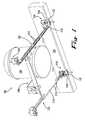
- FIG. 1is a bottom view of a recessed luminaire installation including two hanger bar assemblies.
- FIG. 2is an exploded view of a hanger bar assembly in FIG. 1 where the top plane corresponds to front plane of FIG. 1 .
- FIG. 2Ais a detailed view of the score line configuration shown in FIG. 2 .
- FIG. 3Ais an enlarged front view of an end portion of the hanger bar system of FIG. 2 .
- FIG. 3Bis an enlarged rear view of an end portion of the hanger bar system of FIG. 2 .
- FIG. 3Cis an enlarged side view of an end portion of the hanger bar system of FIG. 2 .
- FIG. 4is an assembled view of the hanger bar assembly of FIG. 2 connected to a plaster plate and arranged in a fully-extended configuration where the side plane corresponds to the top plane of FIG. 2 .
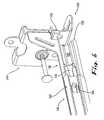
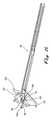
- FIG. 5is an enlarged view of an end portion of the hanger bar system of FIG. 4 , arranged in a partially-extended configuration.
- FIG. 6is an enlarged rear view of the hanger bar assembly of FIG. 5 arranged in a shorter configuration than FIG. 5 .
- FIG. 7Ais a sequential view of the hanger bar assembly of FIG. 6 arranged in a shorter configuration than FIG. 6 .
- FIG. 7Bis a rear view of the hanger bar assembly of FIG. 7A arranged in the same configuration as FIG. 7A .
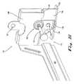
- FIG. 8is an oblique view of the hanger bar system as shown in FIG. 4 , in a retracted position.
- FIG. 9is a side view of the hanger bar assembly shown in FIG. 4 .
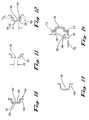
- FIG. 10is a cross-sectional view taken along line 10 - 10 in FIG. 9 .
- FIG. 11is a cross-sectional view taken along line. 11 - 11 in FIG. 9 .
- FIG. 12is a cross-sectional view taken along line 12 - 12 in FIG. 9 .
- FIG. 13is a cross-sectional view taken along line 13 - 13 in FIG. 9 .
- FIG. 14is a partial sectional view of a securing arrangement for a hanger bar system constructed according to the invention.
- FIG. 15is a partial perspective view of the hanger bar system of FIG. 2 , mounted to a support member for a suspended ceiling.
- FIG. 1illustrates a typical installation for a recessed luminaire 100 including a pair of spaced hanger bar assemblies 102 .
- the hanger bar assembliesmay be used with a variety of other recessed and non-recessed luminaires, and/or other devices.
- the hanger bar assemblies 102are preferably attached at each end to horizontal parallel support members, such as the joists 104 shown in FIG. 1 , suspended ceiling T-grids 105 shown in FIG. 15 , and/or steel framing. However, they may also be attached to a variety of other support members that are neither horizontal or parallel.
- the hanger bar assemblies 102support what is broadly referred to here as a suspended member 106 .
- the illustrated suspended memberincludes a housing or “can” 108 that rests on a plaster plate or “frame” 110 .
- the plaster plate 110includes attachment tabs 112 that attach the plaster plate 110 to the hanger bar assemblies 102 .
- the attachment tabs 112may also help to secure the individual hanger bar members of the hanger bar assembly 102 adjacent to each other as discussed below.
- each hanger bar assembly 102includes a first hanger bar member 120 and a second hanger bar member 160 .
- the first hanger bar member 120has a first end 122 with chamfered corners 126 .
- the cornerscan be chamfered at a 45 degree angle relative to the longitudinal direction.
- a variety of other edge finishing techniques and/or surface preparationsmay also be used.
- the first hanger bar member 120includes an elongated slot 130 which is spanned by a first reinforcing bridge 140 to form a first slot portion 131 and a second slot portion 133 .
- the first slot portion 131 of the elongated slot 130has a first width 132 near its first end 122 that extends along a substantial portion of its length.
- the elongated slot 130may also include a second width 134 at the other end, which is greater than the first width 132 .
- the second width 134 of the first slot portion 131is preferably provided in the area of the first reinforcing bridge 140 .
- An angled transitional surface 136(best illustrated in FIG. 9 ) connects the first width 132 with the second width 134 .
- the angled surface 136can be disposed at a 45 degree angle relative to the longitudinal direction as shown in FIG. 9 .
- a variety of other angles and/or curvesmay be used to form the transitional surface 136 .
- score lines 138may be formed across the width of the first hanger bar member 120 .
- the precise form and dimensions of the score lines 138can vary widely. However, in the example illustrated here, the score lines 138 are straight lines and are approximately 0.02 inches deep. In the event that it becomes necessary to fit between relatively narrowly spaced support members, the first hanger bar member 120 can be broken along the score lines 138 to shorten its length. Note, multiple first score lines 138 can be provided on the first hanger bar member 120 . For example, as illustrated in FIG. 2 the score lines may be spaced to account for standard support structure spacings at 1 inch, 4 inches, and 5 inches from the end of the end 122 . Although the score lines 138 are illustrated here as extending across the entire width of the hanger bar member 102 , they may alternatively extend only part way across the width of the hanger bar member.
- one or more of the score lines 170 and/or 138may be arranged with parallel scores on the top and bottom surfaces of the hanger bar for member 120 .
- the score line 170is spaced by a dimension A of about 0.036 inches and include a notch or radius with a dimension B of about 0.016 inches. It has been found that these dimensions provide a hanger bar with sufficient strength without having to provide a break aperture or other hole through the score line such as the score line 170 detailed in the FIGs.
- a second reinforcing bridge 142reaches from one end of the second slot portion 133 to a second end 124 of the first hanger bar member 120 .
- the second slot portion 133also includes first width 132 , which extends along a substantial portion of the longitudinal dimension of the slot portion 133 , and wider a second width 134 .
- the second width 134is provided at both ends of the second slot portion 133 which may also include a transition sections similar to transition section 134 in the slot portion 131 .
- attachment structures 144for securing the hanger bar members to a support, such as a wooden joist 104 ( FIG. 1 ), ceiling T-grid 105 ( FIG. 15 ), and/or steel framing.
- the attachment structures 144may be integrally formed with the first hanger bar member 120 , as illustrated here, or they may be separately formed and subsequently attached to the second end 124 .
- the attachment structures 144include a first wall 146 and a second wall 148 that are parallel to one another and perpendicular to the respective hanger bar member (as shown, second hanger bar member 160 ).
- the first wall 146 and second wall 148are configured such that the second ends 124 and 164 of the opposing hanger bar member 120 and 160 , respectively, can slide beyond the attachment structures 144 when the hanger bar assembly 102 is in a retracted position ( FIG. 8 ).
- the second wall 148includes a fastener aperture 141 formed therein and one or more brace stubs 149 that extend inwardly toward the first wall 146 from the lower edge of the second wall 148 .
- the distal ends of the brace stubs 149are received in stub apertures 147 that are formed in the first wall 146 .
- the brace stubs 149are configured to maintain desired spacing between the first wall 146 and second wall 148 when driving fasteners into support members, such as wooden joists 104 ( FIG. 1 ), as discussed hereafter.
- the fastener aperture 141is configured such that a friction fit is maintained on a fastener 153 ( FIG.
- the first wall 148includes an aperture 141 a that corresponds to the fastener aperture 141 and a mounting flange 152 that depends outwardly from the lower edge of the first wall 146 , such that the first wall 146 and the mounting flange 152 are substantially perpendicular.
- the fastener aperture 141maintains a friction fit with the fastener 153 .
- the corresponding aperture 141 ahas a diameter that is slightly larger than the diameter of the fastener 153 , thereby allowing unimpeded passage of the fastener 153 .
- the corresponding aperture 141 aincludes a lip which depends inwardly toward the second wall 148 . As best seen in FIG. 3C , the inwardly depending lip of the corresponding aperture 141 a is configured to guide the tip of the fastener 153 as it is driven through the corresponding aperture 141 a and into the adjacent support member.
- the attachment structure 144when mounting the first and second hanger bar members 120 and 160 to a support member such as a joist 104 , the attachment structure 144 is positioned adjacent the joist 104 such that the first wall 146 and mounting flange 152 are positioned adjacent the side surface and bottom surface of the joist 104 , respectively.
- a fastener 153such as a screw, nail, etc., is driven through the fastener aperture 141 and corresponding aperture 141 a into the side surface of the joist 104 .
- the fastener 153is preferably maintained in the fastener aperture 141 so that the individual installing the hanger bar assembly 102 need not maintain the fastener 153 in position during installation.
- the fastener 153may be a nail with lands and grooves arranged near the end of the nail for holding it in the aperture 141 . Fully or partially threaded screws, bolts, posts, and/or other ridged fasteners may also be used. Installation is also possible by driving a fastener through any of the various apertures 161 located on the attachment structure 144 .
- an individualcan select to drive an optional fastener (see FIG. 1 ) through a slot 154 formed in the mounting flange 152 and into the bottom surface of the joist 104 .
- an optional fastenersee FIG. 1
- the individualcan now slide the attachment structure 144 longitudinally along the joist 104 over the length of the slot 154 .
- the attachment structure 144can be manipulated until the desired position is found relative to the joist 104 , at which point in time the optional fastener is fully driven into the joist 104 such that the attachment structure 144 and associated hanger bar member are maintained in the desired position.
- the individualmay then install additional fasteners through the fastener aperture 141 and/or additional apertures 161 to further secure the hanger bar assembly 102 to the joist 104 .
- the second wall 148includes a mounting tab 156 extending downwardly from its lower edge.
- the lower portion of the first wall 146 and the mounting tab 156form a gap 155 that is configured to receive the upper rail 105 a of a standard suspended ceiling T-grid 105 , as shown in FIG. 15 .
- opposing catches 158 and 158 aare formed on the lower edge of the mounting tab 156 and the first wall 146 , respectively, such that the attachment structure 144 positively engages the upper rail 105 a of the T-grid 105 .
- the attachment structure 144is secured relative to the T-grid 105 by driving a fastener 153 A, ( FIG. 15 ) preferably a metal screw, through the desired aperture 161 that is positioned adjacent the rail 105 a of the T-grid 105 .
- a second hanger bar member 160nests with the first hanger bar member 120 and includes a first end 162 with chamfered corners 164 similar to the chamfered corners 126 of the first hanger bar member 120 .
- first, second, and third retaining projections 166 , 167 , and 168are provided near the first end 162 of the second hanger bar member 160 .
- the retaining projections 166 , 167 and 168may be cut from the surface of the second hanger bar member 160 and unfolded to provide the form illustrated in FIG. 2 .
- the retaining projections 166 , 167 and 168may be separately formed then attached to the surface of the second hanger bar member 160 .
- alternate embodimentscan include either fewer than, or more than, three retaining projections.
- the retaining projections 166 , 167 , and 168are received within the first and/or second slot portions 131 and 133 of the first hanger bar member 120 in order to couple the hanger members 120 and 160 together in a longitudinally adjustable manner.
- the head of each retaining projectionis greater in width than the first width 132 of the slot portions 131 and 133 , but is smaller than the second width 134 .
- the retaining projections 166 , 167 and 168are dimensioned so as to pass freely under the first and second reinforcing bridges 140 and 142 as the first and second hanger bar members 120 and 160 are longitudinally moved relative to each other.
- Additional score lines 170may be provided across the width of the second hanger bar member 160 .
- the precise form and depthmay vary widely according to the material strength and thickness of the hanger bar members.
- the second score line 170may be a straight line formed to a depth of approximately 0.02 inches. Since second hanger bar member 160 is of a solid cross-section, unlike the slotted first hanger bar member 120 , it is more difficult to break along the second score line 170 . Therefore, an optional score window or aperture 172 may be provided in the area of the score lines 170 in order to facilitate breakage of the second hanger bar member. As noted above, the need for such a break aperture may be avoided by using a score line configuration similar to that for score lines 170 .
- the second hanger bar member 160may be broken along any of the second score lines 170 . As shown in FIG. 2 , breaking the second hanger bar member 160 along the second score line 170 removes the end of the hanger bar 160 having the retaining projections 166 , 167 and 168 . However, the first and second hanger bar members 120 and 160 are still adequately retained by the attachment tabs 112 formed on the plaster plate 110 , as shown in FIG. 8 . It is also possible to simply bend the first and second hanger bar members 120 and 160 as necessary to fit the hanger bar assembly into a narrow space.
- Another attachment structure 144is provided at the second end 164 of the second hanger bar member 160 .
- the attachment structure 144 disposed at the second end 164has the same construction as the first attachment structure located at the second end 124 of the first hanger bar member 120 .
- the elements of such an attachment structure 144have been previously described in connection with the description of first hanger bar member 120 .
- a gap 151is formed between the second end 164 and the first wall 146 such that a portion of the first hanger bar member 120 can slide beyond the attachment structure 144 when the hanger bar assembly 102 is in a retracted position.
- the first and second hanger bar members 120 and 160are secured together in a nested manner.
- the first hanger bar member 120has a first surface 121 that faces the second hanger bar 160 when assembled, and a second opposing surface 123 .
- the second hanger bar member 160includes a third surface 161 which faces away from the first hanger bar 120 when assembled, and a fourth surface 163 which faces the first hanger bar 120 .
- the first and second hanger bar members 120 and 160are connected, the first and fourth surfaces 121 and 163 are received within each other in a nesting relationship.
- the second surface 123faces outwardly (e.g., away from the suspended member 106 ) and the third surface 161 faces inwardly (e.g., toward the suspended member 106 ).
- the retaining projections 166 , 167 and 168may pass freely through the second width 134 without interference.
- the larger second width areas 134facilitate the assembly of the first and second hanger bar members 120 and 160 .
- the first end 122 of the first hanger bar member 120is inserted through the gap 151 formed between the fourth surface 163 and first wall 146 of the second hanger bar member 160 .
- the first hanger bar member 120is then slid longitudinally until at least the second width 134 portion formed on the second bridge 142 has cleared the third retaining projection 168 .
- the first hanger bar member 120is then urged toward the second hanger bar member 160 until the first surface 121 of the first hanger bar member 120 is adjacent the fourth surface 163 of the second hanger bar member 160 .
- the third retaining projection 168is first passed through the second width 134 near the second reinforcing bridge 142 .
- the second hanger bar 160is then moved back relative to the first hanger bar member 120 in the direction of the first end 122 .
- the third retaining projection 168travels in the first width 132 of the second slot portion 133 .
- the second and first retaining projections 167 and 166are then inserted through the second width 134 near the second reinforcing bridge 142 .
- the second and first retaining projections 167 and 166subsequently engage the first width portion 132 of the second slot portion 133 , thereby securing the first and second hanger bar members 120 and 160 .
- FIG. 4also shows a plaster plate 110 slidably attached to the hanger bar assembly 102 by attachment tabs 112 which are configured to slidably receive and maintain the first and. second hanger bar members 120 and 160 adjacent each other.
- One advantage of the illustrated configurationis that, as the first and second hanger bar members 120 and 160 are moved relative to each other, at least two of the retaining projections 166 , 167 , and 168 are engaged within one of the elongated slot portions 131 and 133 .
- One exception to this mode of operationoccurs when both the first and second projections 166 and 167 , or all of the projections, have been passed through the second width 134 of slot portion 133 proximate the second reinforcing bridge 142 .
- this capabilityis provided by arranging the retaining projections 166 , 167 and 168 with a predetermined spacing S 1 between adjacent projections.
- the projection spacing S 1is preferably at least slightly larger than the distance S 2 between the first width regions 132 of the first and second slot portions 131 and 133 , which are separated by the first reinforcing bridge 140 .
- configurationsare envisioned having fewer than three retaining projections.
- a retaining tab 135is disposed on the first hanger bar member 120 near the attachment structure 144 on the second end 124 .
- the retaining tab 135extends outwardly and downwardly from the first hanger bar member 120 opposite the second bridge 142 .
- the retaining tab 135slidably engages the first end 162 of the second hanger bar member 160 as the first retaining projection 166 passes out of the second slot portion 133 of the first hanger bar member 120 . In this way, the retaining tab 135 maintains the first and second hanger bar members 120 and 160 adjacent to each other as the hanger bar assembly 102 is partially retracted.
- FIGS. 7A and 7Bshow the attachments portions 144 of the engaged hanger bar members being slid toward each other. As best seen in FIG. 7B , both the first and second retaining projections 166 and 167 have exited the second slot portion 133 , and the first end 162 of the second hanger bar member 160 has been extended beyond the attachment structure 144 of the first hanger bar member 120 . In this position, the third retaining projection 168 remains within the second slot portion 133 , thereby maintaining the first and second hanger bar members 120 and 160 adjacent one another.
- FIG. 7Bshows the attachments portions 144 of the engaged hanger bar members being slid toward each other. As best seen in FIG. 7B , both the first and second retaining projections 166 and 167 have exited the second slot portion 133 , and the first end 162 of the second hanger bar member 160 has been extended beyond the attachment structure 144 of the first hanger bar member 120 . In this position, the third retaining projection 168 remains within the second slot portion 133
- FIG. 7Balso shows that the gap 151 formed on the attachment structure 144 as it accommodates passage of the retaining projection 166 and thereby permits the first end 162 of the second hanger bar member to extend beyond the attachment structure 144 .
- the attachment structure 144 of the second hanger bar member 160also allows the first end 122 of the first hanger bar member 120 to extend therebeyond.
- FIG. 8shows the hanger bar assembly 102 in a retracted position wherein the front ends 122 and 162 of the first and second hanger bar members 120 and 160 , respectively, extend beyond the attachment structure 144 of the other hanger bar member.
- the first and second score lines 138 and 170also extend beyond the attachment structures 144 such that portions of each hanger bar member 120 and 160 can be removed while the hanger bar members 120 and 160 are still adjacent each other. This permits the overall length of the hanger bar assembly 102 to be reduced without having to remove the hanger bar assembly 102 from the plaster frame 110 .
- the first and second hanger bar members 120 and 160are held adjacent one another by the opposed attachment tabs 112 on the plaster frame 110 .
- FIGS. 10-14show the first and second hanger bar members 120 and 160 in a nested relationship.
- the first hanger bar member 120has a first surface 121 and a second surface 123 .
- the first surface 121has a generally concave groove 127 disposed along a substantial portion of the longitudinal length of the first hanger bar member 120 .
- the second surface 123has a generally convex ridge 129 corresponding to the concave groove 127 formed on the first surface 121 .
- the third surface 161 of the second hanger bar member 160has a generally concave groove 167 extending along a substantial portion of longitudinal length of the second hanger bar member 160 .
- the second hanger bar member 160further has a generally convex ridge 169 disposed on the fourth surface 163 corresponding to the concave groove 127 . As illustrated in FIG. 10 , the generally convex ridge 169 is received in the generally concave groove 127 in a nested manner.
- FIG. 11is a cross-sectional view of the first hanger bar member 120 showing the first width 32 of the elongated slot 130 .
- FIG. 11is a cross-sectional view of the first hanger bar member 120 showing the second width 134 of the elongated slot 130 and just prior to a reinforcing formation.
- FIG. 13is cross-sectional view of the first hanger bar member 120 showing a reinforcing formation in an area that does not include any elongated slot 130 .
- the first and second reinforcing formations 140 and 142each have a generally concave reinforcing depression 143 disposed along first surface 121 and a generally convex reinforcing protrusion 145 or ridge formed along the second surface 123 .
- the generally concave groove 127 that extends along a substantial portion of the first hanger bar member 120defines a first plane P 1 .
- the generally concave reinforcing depressions 143extend beyond the plane P 1 and are therefore formed deeper into the first hanger bar member 120 .
- the generally convex ridge 129that extends along a substantial portion of the longitudinal length of the first hanger bar member 120 defines a second plane P 2 .
- the reinforcing depression 143extends beyond plane P 2 so as to project from the surface of the first hanger bar member 120 and thereby allow passage of retaining projections 166 , 167 and 168 therethrough.
- Various embodiments of the present inventionmay also include a securing arrangement such as the one illustrated in FIG. 14 .
- the securing arrangement for the hanger bar systemfixes the position of the first and second hanger bar members 120 and 160 to each other, as well as fixes the position of the hanger bar assemblies 102 relative to the suspended member.
- the plaster plate 110includes attachment tabs 112 that retain the first and second hanger bars 120 and 160 .
- a securing fastener 180such as a threaded screw, is received in a guide flange member 182 .
- An aperture 184is provided in the plaster plate 110 to provide access to the securing fastener 180 .
- the first bar hanger 120 membermay include more than one reinforcing bridge 140 spanning the elongated slot 130 , with more than two slot portions will exist.
- the first bar hanger 120 membermay include more than one reinforcing bridge 140 spanning the elongated slot 130 , with more than two slot portions will exist.
- as few as two retaining projectionsmay be disposed on the second hanger bar member 160 .
- the gap 151may be removed from the attached structures 144 where the structures do not extend far enough down so as to impede the passage of the front end of either bar member 120 , 160 or the retaining projections.
Landscapes
- Engineering & Computer Science (AREA)
- General Engineering & Computer Science (AREA)
- Mechanical Engineering (AREA)
- Holders For Apparel And Elements Relating To Apparel (AREA)
- Mutual Connection Of Rods And Tubes (AREA)
- Floor Finish (AREA)
Abstract
Description
Claims (18)
Priority Applications (4)
| Application Number | Priority Date | Filing Date | Title |
|---|---|---|---|
| US13/559,991US8622361B2 (en) | 2004-03-25 | 2012-07-27 | Hanger bar for recessed luminaires with integral nail |
| US14/148,218US9004435B2 (en) | 2004-03-25 | 2014-01-06 | Hanger bar for recessed luminaires with integral nail |
| US14/677,513US9689541B2 (en) | 2004-03-25 | 2015-04-02 | Hanger bar for recessed luminaires with integral nail |
| US15/267,971US9696021B2 (en) | 2004-03-25 | 2016-09-16 | Hanger bar for recessed luminaires |
Applications Claiming Priority (6)
| Application Number | Priority Date | Filing Date | Title |
|---|---|---|---|
| US55625104P | 2004-03-25 | 2004-03-25 | |
| US10/842,115US20050247842A1 (en) | 2004-05-10 | 2004-05-10 | Hanger bar assemblies for recessed luminaires |
| US11/090,654US7673841B2 (en) | 2004-03-25 | 2005-03-25 | Hangar bar for recessed luminaires with integral nail |
| US12/122,945US7735795B2 (en) | 2004-03-25 | 2008-05-19 | Hangar bar for recessed luminaires with integral nail |
| US12/769,275US8240630B2 (en) | 2004-03-25 | 2010-04-28 | Hanger bar for recessed luminaires with integral nail |
| US13/559,991US8622361B2 (en) | 2004-03-25 | 2012-07-27 | Hanger bar for recessed luminaires with integral nail |
Related Parent Applications (1)
| Application Number | Title | Priority Date | Filing Date |
|---|---|---|---|
| US12/769,275ContinuationUS8240630B2 (en) | 2004-03-25 | 2010-04-28 | Hanger bar for recessed luminaires with integral nail |
Related Child Applications (1)
| Application Number | Title | Priority Date | Filing Date |
|---|---|---|---|
| US14/148,218ContinuationUS9004435B2 (en) | 2004-03-25 | 2014-01-06 | Hanger bar for recessed luminaires with integral nail |
Publications (2)
| Publication Number | Publication Date |
|---|---|
| US20120292475A1 US20120292475A1 (en) | 2012-11-22 |
| US8622361B2true US8622361B2 (en) | 2014-01-07 |
Family
ID=35006290
Family Applications (6)
| Application Number | Title | Priority Date | Filing Date |
|---|---|---|---|
| US11/090,654Active2027-07-21US7673841B2 (en) | 2004-03-25 | 2005-03-25 | Hangar bar for recessed luminaires with integral nail |
| US12/122,945Expired - LifetimeUS7735795B2 (en) | 2004-03-25 | 2008-05-19 | Hangar bar for recessed luminaires with integral nail |
| US12/769,275Expired - LifetimeUS8240630B2 (en) | 2004-03-25 | 2010-04-28 | Hanger bar for recessed luminaires with integral nail |
| US13/559,991Expired - LifetimeUS8622361B2 (en) | 2004-03-25 | 2012-07-27 | Hanger bar for recessed luminaires with integral nail |
| US14/148,218Expired - LifetimeUS9004435B2 (en) | 2004-03-25 | 2014-01-06 | Hanger bar for recessed luminaires with integral nail |
| US14/677,513Expired - Fee RelatedUS9689541B2 (en) | 2004-03-25 | 2015-04-02 | Hanger bar for recessed luminaires with integral nail |
Family Applications Before (3)
| Application Number | Title | Priority Date | Filing Date |
|---|---|---|---|
| US11/090,654Active2027-07-21US7673841B2 (en) | 2004-03-25 | 2005-03-25 | Hangar bar for recessed luminaires with integral nail |
| US12/122,945Expired - LifetimeUS7735795B2 (en) | 2004-03-25 | 2008-05-19 | Hangar bar for recessed luminaires with integral nail |
| US12/769,275Expired - LifetimeUS8240630B2 (en) | 2004-03-25 | 2010-04-28 | Hanger bar for recessed luminaires with integral nail |
Family Applications After (2)
| Application Number | Title | Priority Date | Filing Date |
|---|---|---|---|
| US14/148,218Expired - LifetimeUS9004435B2 (en) | 2004-03-25 | 2014-01-06 | Hanger bar for recessed luminaires with integral nail |
| US14/677,513Expired - Fee RelatedUS9689541B2 (en) | 2004-03-25 | 2015-04-02 | Hanger bar for recessed luminaires with integral nail |
Country Status (2)
| Country | Link |
|---|---|
| US (6) | US7673841B2 (en) |
| CA (1) | CA2502637C (en) |
Cited By (49)
| Publication number | Priority date | Publication date | Assignee | Title |
|---|---|---|---|---|
| US9004435B2 (en) | 2004-03-25 | 2015-04-14 | Cooper Technologies Company | Hanger bar for recessed luminaires with integral nail |
| US9060607B1 (en) | 2012-10-17 | 2015-06-23 | Cooper Technologies Company | Hanger bar for recessed light fixture mounting |
| US20150259930A1 (en)* | 2012-08-21 | 2015-09-17 | Michael Wayne Strickland | Installation Assist and Method |
| US9239131B1 (en) | 2015-06-05 | 2016-01-19 | Cooper Technologies Company | Adjustable hanger bars with detachment stop |
| US9303812B2 (en) | 2013-04-05 | 2016-04-05 | Cooper Technologies Company | Adjustable hanger bar for luminaires |
| US20170059139A1 (en) | 2015-08-26 | 2017-03-02 | Abl Ip Holding Llc | Led luminaire |
| US9696021B2 (en) | 2004-03-25 | 2017-07-04 | Cooper Technologies Company | Hanger bar for recessed luminaires |
| US9732904B1 (en) | 2015-06-05 | 2017-08-15 | Cooper Technologies Company | Adjustable hanger bar assembly for luminaires |
| USD803459S1 (en) | 2013-04-22 | 2017-11-21 | Cooper Technologies Company | Edgelit garage luminaire |
| US10012366B2 (en) | 2015-01-19 | 2018-07-03 | John-Paul Belmonte | Pot light assembly |
| US10234114B1 (en) | 2015-06-05 | 2019-03-19 | Cordelia Lighting Inc. | LED module and assembly |
| US10251279B1 (en) | 2018-01-04 | 2019-04-02 | Abl Ip Holding Llc | Printed circuit board mounting with tabs |
| US10408395B2 (en) | 2013-07-05 | 2019-09-10 | DMF, Inc. | Recessed lighting systems |
| USD864877S1 (en) | 2019-01-29 | 2019-10-29 | DMF, Inc. | Plastic deep electrical junction box with a lighting module mounting yoke |
| US10488000B2 (en) | 2017-06-22 | 2019-11-26 | DMF, Inc. | Thin profile surface mount lighting apparatus |
| US10551044B2 (en) | 2015-11-16 | 2020-02-04 | DMF, Inc. | Recessed lighting assembly |
| US10563850B2 (en) | 2015-04-22 | 2020-02-18 | DMF, Inc. | Outer casing for a recessed lighting fixture |
| US10584837B2 (en) | 2016-10-28 | 2020-03-10 | Cordelia Lighting, Inc. | Bar hanger system for recessed fixtures |
| US10591120B2 (en) | 2015-05-29 | 2020-03-17 | DMF, Inc. | Lighting module for recessed lighting systems |
| US10663153B2 (en) | 2017-12-27 | 2020-05-26 | DMF, Inc. | Methods and apparatus for adjusting a luminaire |
| US10753558B2 (en) | 2013-07-05 | 2020-08-25 | DMF, Inc. | Lighting apparatus and methods |
| USD901398S1 (en) | 2019-01-29 | 2020-11-10 | DMF, Inc. | Plastic deep electrical junction box |
| USD902871S1 (en) | 2018-06-12 | 2020-11-24 | DMF, Inc. | Plastic deep electrical junction box |
| USD905327S1 (en) | 2018-05-17 | 2020-12-15 | DMF, Inc. | Light fixture |
| USD907284S1 (en) | 2014-02-18 | 2021-01-05 | DMF, Inc. | Module applied to a lighting assembly |
| US10975570B2 (en) | 2017-11-28 | 2021-04-13 | DMF, Inc. | Adjustable hanger bar assembly |
| US11060705B1 (en) | 2013-07-05 | 2021-07-13 | DMF, Inc. | Compact lighting apparatus with AC to DC converter and integrated electrical connector |
| US11067231B2 (en) | 2017-08-28 | 2021-07-20 | DMF, Inc. | Alternate junction box and arrangement for lighting apparatus |
| US11231154B2 (en) | 2018-10-02 | 2022-01-25 | Ver Lighting Llc | Bar hanger assembly with mating telescoping bars |
| US11255497B2 (en) | 2013-07-05 | 2022-02-22 | DMF, Inc. | Adjustable electrical apparatus with hangar bars for installation in a building |
| USD944212S1 (en) | 2015-10-05 | 2022-02-22 | DMF, Inc. | Electrical junction box |
| USD945054S1 (en) | 2017-06-22 | 2022-03-01 | DMF, Inc. | Light fixture |
| US11274821B2 (en) | 2019-09-12 | 2022-03-15 | DMF, Inc. | Lighting module with keyed heat sink coupled to thermally conductive trim |
| US11306903B2 (en) | 2020-07-17 | 2022-04-19 | DMF, Inc. | Polymer housing for a lighting system and methods for using same |
| US11342733B2 (en) | 2020-03-09 | 2022-05-24 | Erico International Corporation | Bracket system for mounting electrical boxes |
| US11349289B2 (en) | 2019-09-19 | 2022-05-31 | Erico International Corporation | Mounting bracket for electrical boxes |
| US11391442B2 (en) | 2018-06-11 | 2022-07-19 | DMF, Inc. | Polymer housing for a recessed lighting system and methods for using same |
| US11402121B2 (en)* | 2015-03-25 | 2022-08-02 | Sterling Custom Sheet Metal, Inc. | Insulated register box with boot rail adaptor |
| US11435064B1 (en) | 2013-07-05 | 2022-09-06 | DMF, Inc. | Integrated lighting module |
| USD966877S1 (en) | 2019-03-14 | 2022-10-18 | Ver Lighting Llc | Hanger bar for a hanger bar assembly |
| US11495952B2 (en) | 2019-09-18 | 2022-11-08 | Erico International Corporation | Bracket system for mounting electrical boxes |
| USD970081S1 (en) | 2018-05-24 | 2022-11-15 | DMF, Inc. | Light fixture |
| US11585517B2 (en) | 2020-07-23 | 2023-02-21 | DMF, Inc. | Lighting module having field-replaceable optics, improved cooling, and tool-less mounting features |
| USD990030S1 (en) | 2020-07-17 | 2023-06-20 | DMF, Inc. | Housing for a lighting system |
| US11817688B2 (en) | 2020-10-19 | 2023-11-14 | Erico International Corporation | Box and conduit hanger |
| USD1012864S1 (en) | 2019-01-29 | 2024-01-30 | DMF, Inc. | Portion of a plastic deep electrical junction box |
| US12203631B2 (en) | 2020-07-16 | 2025-01-21 | DMF, Inc. | Round metal housing for a lighting system |
| US12297986B2 (en) | 2020-07-17 | 2025-05-13 | DMF, Inc. | Bar hanger assembly with crossmembers and housing assemblies using same |
| US12372200B2 (en) | 2019-06-03 | 2025-07-29 | Erico International Corporation | Mounting bracket for electrical boxes |
Families Citing this family (47)
| Publication number | Priority date | Publication date | Assignee | Title |
|---|---|---|---|---|
| US20050247842A1 (en)* | 2004-05-10 | 2005-11-10 | Grzegorz Wronski | Hanger bar assemblies for recessed luminaires |
| US7874539B2 (en)* | 2005-09-30 | 2011-01-25 | Hubbell Incorporated | Integral nail bar hanger for recessed luminaire |
| US7896529B2 (en)* | 2006-06-01 | 2011-03-01 | Cooper Technologies Company | Surface-mounted lighting system |
| US7540460B2 (en)* | 2006-06-16 | 2009-06-02 | Britannia Investment Corporation | Mounting assembly |
| US8177176B2 (en)* | 2007-03-12 | 2012-05-15 | Cordelia Lighting, Inc. | Hanger bar for recessed lighting fixtures |
| US7810775B2 (en)* | 2007-03-12 | 2010-10-12 | Cordelia Lighting, Inc. | Hanger bar for recessed lighting fixtures |
| US7874711B2 (en)* | 2008-01-08 | 2011-01-25 | Cooper Technologies Company | Surface-mounted lighting system |
| US7784979B2 (en) | 2008-05-05 | 2010-08-31 | Cooper Technologies Company | Reflector assembly for a recessed luminaire |
| US20100270446A1 (en)* | 2009-04-28 | 2010-10-28 | Phillips Bruce G | Universal Adjustable Box Bracket |
| US9062485B2 (en)* | 2009-07-07 | 2015-06-23 | Michael John Guidos | Articulating roller arm assembly |
| US8309849B2 (en)* | 2009-07-30 | 2012-11-13 | Thomas & Betts International, Inc. | Attachable supporting spacer for electrical boxes |
| US9492037B2 (en)* | 2009-10-23 | 2016-11-15 | Christopher M. Kee | Hybrid enclosure system |
| CA2691480C (en)* | 2009-11-12 | 2012-04-10 | Cordelia Lighting Inc. | Hanger bar for recessed lighting fixtures |
| USD623347S1 (en)* | 2010-02-04 | 2010-09-07 | Foxsemicon Integrated Technology, Inc. | Lamp supporting device |
| USD623348S1 (en)* | 2010-02-04 | 2010-09-07 | Foxsemicon Integrated Technology, Inc. | Lamp supporting device |
| USD623346S1 (en)* | 2010-02-04 | 2010-09-07 | Foxsemicon Integrated Technology, Inc. | Lamp supporting device |
| USD623349S1 (en)* | 2010-02-04 | 2010-09-07 | Foxsemicon Integrated Technology, Inc. | Lamp supporting device |
| USD623350S1 (en)* | 2010-02-04 | 2010-09-07 | Foxsemicon Integrated Technology, Inc. | Lamp supporting device |
| US8561961B1 (en) | 2010-02-25 | 2013-10-22 | Cooper Technologies Company | Captive hardware for improved installation |
| USD623344S1 (en)* | 2010-04-02 | 2010-09-07 | Foxsemicon Integrated Technology, Inc. | LED lamp hanger fixture |
| USD640123S1 (en) | 2011-01-03 | 2011-06-21 | Tracfone Wireless, Inc. | Adjustable display bracket |
| USD640122S1 (en) | 2011-01-03 | 2011-06-21 | Tracfone Wireless, Inc. | Adjustable display bracket |
| US9622623B2 (en) | 2011-07-19 | 2017-04-18 | Christopher Marshal KEE | Enclosure systems |
| CN103016925B (en)* | 2011-09-26 | 2016-03-23 | 广东松下环境系统有限公司 | For the mounting bracket of integrated ceiling appliance |
| US20130099083A1 (en)* | 2011-10-21 | 2013-04-25 | Brainwave Research Corporation | Resilient ceiling support system and apparatus |
| US10907843B2 (en)* | 2011-11-18 | 2021-02-02 | Broan-Nutone Llc | Ventilating system and method |
| USD677418S1 (en)* | 2012-05-17 | 2013-03-05 | Osram Sylvania Inc. | Ceiling mounted luminaire |
| US10030421B2 (en) | 2014-02-12 | 2018-07-24 | Kls Doors, Llc | Latch and lock system |
| US9784437B2 (en) | 2014-02-14 | 2017-10-10 | Hussmann Corporation | Adjustable light mechanism for a merchandiser |
| USD718489S1 (en)* | 2014-04-01 | 2014-11-25 | Cooper Technologies Company | Recessed luminaire housing top |
| USD789595S1 (en) | 2015-07-23 | 2017-06-13 | Ip Holdings, Llc | Ballast hanging bracket |
| US10151427B2 (en)* | 2015-11-20 | 2018-12-11 | Lee Mattson | Overhead mountable storage system |
| US10006613B2 (en) | 2016-04-20 | 2018-06-26 | Tripar Inc. | Bar hanger with substantially identical members for recessed luminaires |
| CN109690175A (en)* | 2016-08-29 | 2019-04-26 | 昕诺飞控股有限公司 | Fixing piece installation system and method |
| US10541522B2 (en)* | 2016-11-15 | 2020-01-21 | Thomas & Betts International Llc | Electrical box bar hanger |
| US11330904B2 (en)* | 2016-12-19 | 2022-05-17 | Arthur KHALIQ | Apparatus for improving support strength of planar surfaces |
| USD819879S1 (en) | 2017-02-09 | 2018-06-05 | Tripar Inc. | Bar hanger |
| US10561873B2 (en)* | 2018-02-23 | 2020-02-18 | Anvil International, Llc | Angled bracket for a fire sprinkler support assembly |
| US10712046B2 (en)* | 2018-04-27 | 2020-07-14 | AUPU Home Style Corporation Limited. | Ventilator mounting bracket |
| CN109058814A (en)* | 2018-06-27 | 2018-12-21 | 宁波建辰新型材料有限公司 | A kind of bathroom lamp mounting structure |
| US10746381B1 (en)* | 2018-09-28 | 2020-08-18 | Suzhou Rongwen Kubai Lighting System Corp., Ltd. | System and method for providing a recessed luminaire |
| EP3747312A1 (en)* | 2019-06-05 | 2020-12-09 | Rol Ergo AB | A bar for supporting a table |
| USD986479S1 (en) | 2020-08-17 | 2023-05-16 | Klus, Llc | Extrusion for LED based lighting apparatus |
| US11255519B1 (en) | 2020-08-17 | 2022-02-22 | Klus, Llc | Dual extrusion system for led light fixture |
| US12431041B2 (en)* | 2021-03-23 | 2025-09-30 | SignWay Corp | Display bars and display bar assemblies for supporting display objects |
| KR102715426B1 (en)* | 2022-11-11 | 2024-10-11 | (주)루니코 | Storage Furniture having Reinforced Shelf |
| US12371894B2 (en)* | 2023-08-28 | 2025-07-29 | Michael Allen Rasmussen | Hanger assembly for use on open web steel joists or beams |
Citations (144)
| Publication number | Priority date | Publication date | Assignee | Title |
|---|---|---|---|---|
| US1156885A (en) | 1911-12-12 | 1915-10-19 | New England Electric Company | Outlet-box bracket. |
| US1350295A (en) | 1919-04-18 | 1920-08-24 | Kirby Champeau Co Inc | Illuminating means |
| US1622087A (en) | 1924-03-06 | 1927-03-22 | Nat Metal Molding Company | Bar hanger for the support of outlet boxes for the wiring of buildings |
| US1756361A (en) | 1926-09-11 | 1930-04-29 | Jefferson Electric Co | Outlet-box mounting |
| US1791480A (en) | 1929-02-07 | 1931-02-03 | Midwest Metal Products Company | Hanger device for electric fixtures |
| US1821733A (en) | 1929-10-16 | 1931-09-01 | Ralph W Thibodeau | Glare deflector |
| US2316389A (en) | 1940-08-03 | 1943-04-13 | Earl B Atkinson | Adjustable bar hanger and receptacle fastening means |
| US2518515A (en) | 1949-06-20 | 1950-08-15 | Marcello R Austin | Bracket for attaching electrical fixtures and conduit and other conduits to roof andfloor decking |
| US2658241A (en) | 1950-07-10 | 1953-11-10 | Jr Dale B Houghton | Bridging |
| US2713983A (en) | 1953-02-09 | 1955-07-26 | Kay Michael | Expansible hanger bars for supporting electric outlet boxes |
| US2802933A (en) | 1955-05-31 | 1957-08-13 | Perfect Line Mfg Corp | Lighting fixture |
| US2887568A (en) | 1957-02-26 | 1959-05-19 | Holophane Co Inc | Ceiling luminaire |
| US2930564A (en) | 1956-11-13 | 1960-03-29 | Robert W Maier | Fixture support for hung ceilings |
| US2933549A (en) | 1957-05-28 | 1960-04-19 | James A Antonucci | Support device for an outlet box |
| US3040172A (en) | 1958-11-12 | 1962-06-19 | Lightolier Inc | Lighting fixture |
| US3099404A (en) | 1961-11-13 | 1963-07-30 | Markstone Mfg Company | Recessed lighting fixtures |
| US3102306A (en) | 1959-08-27 | 1963-09-03 | Herman O Mcpheeters | Method of manufacturing bracing |
| US3104087A (en) | 1961-03-21 | 1963-09-17 | Electrical Fittings Corp | Means for supporting electrical fixtures |
| US3154001A (en) | 1960-09-22 | 1964-10-27 | Garey Corp | Fluorescent light fixture |
| US3162413A (en) | 1962-04-26 | 1964-12-22 | Andrew M Hexdall | Bar hanger |
| US3300634A (en) | 1963-09-30 | 1967-01-24 | Liberman Milton | Lighting fixture and mount therefor |
| US3313931A (en) | 1962-05-14 | 1967-04-11 | Sterling Ind Inc | Telescoping recessed lighting fixture |
| US3597889A (en) | 1969-10-08 | 1971-08-10 | Antonio Lo Nigro | Junction box suspension unit for suspended ceilings |
| US3609338A (en) | 1968-09-18 | 1971-09-28 | Esquire Inc | Light fixture |
| US3710096A (en) | 1971-12-07 | 1973-01-09 | Esquire Inc | Adjustable support for light fixtures |
| US4022415A (en) | 1975-09-02 | 1977-05-10 | Galgon Industries, Inc. | Support for tie back and return of drapery |
| US4040589A (en) | 1975-04-03 | 1977-08-09 | Mclay Roger Berry Cameron | Interconnecting bracket for logs |
| US4041657A (en) | 1975-09-18 | 1977-08-16 | Fastway Fasteners, Inc. | Fixture support for grid type ceiling |
| US4086480A (en) | 1976-09-24 | 1978-04-25 | Donn Products, Inc. | Suspension ceiling and recessed lighting system |
| US4114327A (en) | 1977-05-13 | 1978-09-19 | Williams Arthur C | Light fixture support |
| US4122762A (en) | 1977-03-07 | 1978-10-31 | Williams Arthur C | Air-slot spacer clip |
| US4149693A (en) | 1977-12-02 | 1979-04-17 | Lonigro Antonio | Fixture support with twisted central portion |
| US4165851A (en) | 1977-09-28 | 1979-08-28 | Slater Electric Inc. | Adjustably lockable bar hanger for ceiling boxes and the like |
| US4190355A (en) | 1978-05-03 | 1980-02-26 | Xerox Corporation | Facetted reflector |
| US4230900A (en) | 1978-06-13 | 1980-10-28 | Steelcase Inc., | Power pole assembly |
| US4290098A (en) | 1979-08-10 | 1981-09-15 | Betts Machine Company | Receptacle apparatus for housing components of a lighting system |
| US4336575A (en) | 1980-09-04 | 1982-06-22 | Kidde Consumer Durables Corp. | Breakaway plaster frame |
| US4388677A (en) | 1981-01-02 | 1983-06-14 | Prescolite, A Div. Of U.S. Industries | Recessed lighting unit |
| US4391428A (en) | 1981-11-16 | 1983-07-05 | Lance Austin Enterprises, Inc. | Lance-type fixture support and method of use |
| US4406216A (en) | 1981-05-08 | 1983-09-27 | Philips Industries, Inc. | Ventilator device and mounting arrangement therefor |
| US4408262A (en) | 1982-06-01 | 1983-10-04 | Mcgraw-Edison Company | Plaster frame for recessed lighting |
| US4475147A (en) | 1982-08-19 | 1984-10-02 | Mcgraw-Edison Company | Adjustable wall wash reflector assembly for a recess mounted lighting fixture |
| US4511113A (en) | 1981-01-02 | 1985-04-16 | Prescolite, A Division Of U.S. Industries | Hangar device for a recessed lighting unit |
| US4519019A (en) | 1983-04-22 | 1985-05-21 | Quantum Lighting Limited | Ceiling light fitting |
| US4545000A (en) | 1983-10-03 | 1985-10-01 | Gte Products Corporation | Projection lamp unit |
| US4564888A (en) | 1984-11-28 | 1986-01-14 | Linear Lighting Corp. | Wall-wash lighting fixture |
| US4566057A (en) | 1981-01-02 | 1986-01-21 | Prescolite, Inc. | Recessed lighting housing |
| US4569003A (en) | 1984-10-19 | 1986-02-04 | Elmer William B | Interior indirect lighting |
| US4577824A (en) | 1984-07-09 | 1986-03-25 | Prescolite, Inc. | Fastening device for fixing a body to a structural member |
| US4646212A (en) | 1985-11-15 | 1987-02-24 | Lightolier Incorporated | Recessed lighting fixture |
| US4670822A (en) | 1983-11-19 | 1987-06-02 | Lucas Industries Public Limited Company | Light assembly |
| US4723747A (en) | 1986-10-24 | 1988-02-09 | Capri Lighting | Bar hangers for recessed lighting fixtures |
| US4729080A (en) | 1987-01-29 | 1988-03-01 | Juno Lighting, Inc. | Sloped ceiling recessed light fixture |
| US4742440A (en) | 1986-07-29 | 1988-05-03 | Iguzzini Illuminazione S.P.A. | Lighting device with asymmetrical light beam |
| US4754377A (en) | 1986-02-21 | 1988-06-28 | Thomas Industries, Inc. | Thermally protected recessed lighting fixture |
| US4757967A (en) | 1986-09-02 | 1988-07-19 | Erico International Corporation | Box support |
| US4760510A (en) | 1987-05-18 | 1988-07-26 | Lahti Uolevi L | Simple mounting for electrical fixture |
| US4760981A (en) | 1986-12-04 | 1988-08-02 | Hodges Bonnie E | Heating boot hanger assembly |
| US4762162A (en) | 1985-02-08 | 1988-08-09 | Chochrek Frank S | Shade brackets and assembly |
| US4796169A (en) | 1987-05-08 | 1989-01-03 | Sylvan R. Shemitz Associates, Inc. | Lighting fixture with rotatable glareshield |
| US4803603A (en) | 1988-02-16 | 1989-02-07 | Thomas Industries, Inc. | Plaster frame |
| US4829410A (en) | 1987-06-17 | 1989-05-09 | Emerson Electric Co. | Ceiling mounted luminaire housing system |
| US4872097A (en) | 1988-12-05 | 1989-10-03 | Miller Jack V | Miniature low-voltage lighting fixture |
| US4930054A (en) | 1988-12-09 | 1990-05-29 | Nutone, Inc. | Dual cone recessed lighting fixture |
| US4967990A (en) | 1989-01-26 | 1990-11-06 | B-Line Systems, Inc. | Support for an electrical box |
| US4972339A (en) | 1990-03-15 | 1990-11-20 | Juno Lighting, Inc. | Recessed light fixture assembly |
| US4978092A (en) | 1989-06-22 | 1990-12-18 | Commander Electrical Materials, Inc. | Universal support bracket for attachment to the back of an electrical box |
| US5029794A (en) | 1989-09-22 | 1991-07-09 | Prescolite, Inc. | Universal captive bar hanger |
| US5034867A (en) | 1990-07-05 | 1991-07-23 | Blazer International Corporation | Fluted lamp reflector |
| US5044582A (en) | 1990-03-07 | 1991-09-03 | Trade Source International | Ceiling fan support |
| US5045985A (en) | 1990-03-15 | 1991-09-03 | Lightolier, Inc. | Self locking adjustable mounting bars |
| US5057979A (en) | 1989-12-12 | 1991-10-15 | Thomas Industries, Inc. | Recessed lighting fixture |
| US5073845A (en) | 1989-04-10 | 1991-12-17 | Janice Industries, Inc. | Fluorescent retrofit light fixture |
| US5075828A (en) | 1986-05-19 | 1991-12-24 | Musco Corporation | Glare control lamp and reflector assembly and method for glare control |
| US5074515A (en) | 1990-05-18 | 1991-12-24 | Fasco Industries, Inc. | Hanger bar for ceiling fixtures |
| US5075831A (en) | 1991-02-07 | 1991-12-24 | Hubbell Incorporated | Lighting fixture assembly |
| US5130913A (en) | 1990-05-15 | 1992-07-14 | Francis David | Lighting device with dichroic reflector |
| US5176345A (en) | 1991-01-10 | 1993-01-05 | Medlin Pauline B | Extension plate for outlet box bracket |
| US5178503A (en) | 1991-05-02 | 1993-01-12 | Al Losada | Fastener assembly having flat surface for stabilizing the barrel of a power actuated gun |
| US5209444A (en) | 1989-01-26 | 1993-05-11 | B-Line Systems, Inc. | Support for an electrical box |
| US5222800A (en) | 1992-01-28 | 1993-06-29 | The Genlyte Group Incorporated | Recessed lighting fixture |
| US5291381A (en) | 1993-04-23 | 1994-03-01 | Edison Price | Light fixture mounting assembly |
| US5316254A (en) | 1992-05-14 | 1994-05-31 | Mccartha Robert D | Junction box support for suspended ceilings |
| USD351481S (en) | 1993-01-22 | 1994-10-11 | Litecontrol Corporation | Recessed fluorescent lighting fixture |
| US5379199A (en) | 1993-01-06 | 1995-01-03 | Progress Lighting | Low profile recessed wall lighting fixture |
| US5386959A (en) | 1988-12-14 | 1995-02-07 | Erico International Corporation | Box support |
| US5457617A (en) | 1993-06-17 | 1995-10-10 | Lightolier Division Of The Genlyte Group Incorporated | Sloped recessed lighting fixture |
| US5505419A (en) | 1994-03-28 | 1996-04-09 | Juno Lighting, Inc. | Bar hanger for a recessed light fixture assembly |
| US5571256A (en) | 1994-10-25 | 1996-11-05 | Compaq Computer Corporation | Server drawer slide mount apparatus for a rack-mounted computer system |
| US5581448A (en) | 1995-08-08 | 1996-12-03 | Harwood; Ronald P. | Display lighting system for walls |
| US5588737A (en) | 1994-11-10 | 1996-12-31 | Thomas Industries, Inc. | Modular recessed lighting system |
| US5595028A (en) | 1995-01-31 | 1997-01-21 | Handzlik; Walter A. | Truss roof and floor joist storage device |
| US5597234A (en) | 1994-05-02 | 1997-01-28 | Cooper Industries, Inc. | Trim retainer |
| US5619263A (en) | 1995-03-21 | 1997-04-08 | Erico International Corporation | Box hanger and method |
| US5618017A (en) | 1993-07-09 | 1997-04-08 | De Boer; Hermanus P. M. | Supporting plate unit for ceiling |
| US5623789A (en) | 1994-09-12 | 1997-04-29 | Kidwell; Steven A. | Pitch stabilizing, positionable eaves-overhang light support assembly |
| US5662413A (en) | 1996-05-07 | 1997-09-02 | Cooper Industries, Inc. | Trim for recessed lighting fixture |
| US5662414A (en) | 1996-05-03 | 1997-09-02 | Nsi Enterprises, Inc. | Thermoplastic pan assembly for mounting recessed lighting fixtures in ceilings and the like |
| USD384431S (en) | 1996-04-08 | 1997-09-30 | Jacques Bitton | Recessed lighting fixture |
| US5678799A (en) | 1995-06-07 | 1997-10-21 | Hubbell Incorporated | Adjustable hanger assembly |
| US5690423A (en) | 1996-03-04 | 1997-11-25 | Nsi Enterprises, Inc. | Wire frame pan assembly for mounting recessed lighting in ceilings and the like |
| US5738436A (en) | 1996-09-17 | 1998-04-14 | M.G. Products, Inc. | Modular lighting fixture |
| US5746507A (en) | 1997-01-06 | 1998-05-05 | Thomas Industries, Inc. | Recessed lighting fixture for two light sizes |
| US5758959A (en) | 1996-05-17 | 1998-06-02 | Progress Lighting, Inc. | Recessed lamp fixture |
| US5800051A (en) | 1995-11-20 | 1998-09-01 | Heraeus Med Gmbh | Medical lamp with multi-component projector unit |
| US5826970A (en) | 1996-12-17 | 1998-10-27 | Effetre U.S.A. | Light transmissive trim plate for recessed lighting fixture |
| US5845886A (en) | 1996-07-26 | 1998-12-08 | Mccormick; Henry | Adjustable ceiling fan support assembly |
| US5873556A (en) | 1995-03-13 | 1999-02-23 | Reiker; Kenneth H. | Adjustable drop ceiling fixture support |
| US5934631A (en) | 1996-08-19 | 1999-08-10 | Thomas & Betts Corporation | Hanger bar assembly |
| US5954304A (en) | 1996-10-25 | 1999-09-21 | Hubbell Incorporated | Adjustable hanger assembly |
| US5957573A (en) | 1997-09-05 | 1999-09-28 | Lightolier Division Of The Genlyte Group Inc. | Recessed fixture frame and method |
| US6030102A (en) | 1998-12-23 | 2000-02-29 | Cooper Technologies Company | Trim retention system for recessed lighting fixture |
| US6033098A (en) | 1998-07-30 | 2000-03-07 | Nsi Enterprises Inc. | Bar hanger clip |
| US6076788A (en) | 1998-06-22 | 2000-06-20 | Cooper Industries | Reinforced hanger bar |
| US6082878A (en) | 1998-02-03 | 2000-07-04 | Cooper Industries, Inc. | Fully rotatable recessed light fixture with movable stop and adjustable length bar hanger |
| US6105918A (en) | 1998-04-24 | 2000-08-22 | Cooper Technologies Company | Single piece adjustable hanger bar for lighting fixtures |
| US6164802A (en) | 1998-12-23 | 2000-12-26 | Cooper Technologies Company | Stackable housing |
| US6216992B1 (en) | 1999-03-04 | 2001-04-17 | Elkay Manufacturing Company | Mounting device for securing a sink to a countertop and method of using same |
| US6231205B1 (en) | 1998-10-23 | 2001-05-15 | Powerwall, Inc. | Illuminated shelving |
| US6286265B1 (en) | 2000-02-01 | 2001-09-11 | Cooper Technologies Company | Recessed lighting fixture mounting |
| US6296211B1 (en) | 1996-10-15 | 2001-10-02 | Snyder National Corporation | Duct and pipe bracket for use between joists |
| US6332597B1 (en) | 1998-03-19 | 2001-12-25 | Hubbell Incorporated | Mounting bracket and supporting brace |
| US6341466B1 (en) | 2000-01-19 | 2002-01-29 | Cooper Technologies Company | Clip for securing an elongate member to a T-bar of a ceiling grid |
| US6345800B1 (en) | 1998-07-27 | 2002-02-12 | Nsi Enterprises, Inc. | Universal load-bearing hanger bracket and method for hanging a lighting fixture below a grid ceiling system at on-grid or off-grid locations |
| US6431723B1 (en) | 2000-04-28 | 2002-08-13 | Cooper Technologies, Company | Recessed lighting fixture |
| US6461016B1 (en) | 2000-10-25 | 2002-10-08 | Hubbell Incorporated | Adjustable recessed downlight |
| US6471374B1 (en) | 2000-06-30 | 2002-10-29 | Genlyte Thomas Group Llc | Accent light adjustable assembly |
| US6484980B2 (en) | 2000-07-21 | 2002-11-26 | Lewis B. Medlin, Sr. | Field bendable tab for electrical box support |
| US6505960B2 (en) | 2001-03-19 | 2003-01-14 | Cooper Industries, Inc. | Recessed lighting fixture locking assembly |
| US6519791B2 (en) | 2001-07-03 | 2003-02-18 | Securus, Inc. | Stub-out bar |
| US6527406B1 (en) | 1996-04-12 | 2003-03-04 | Powerwall, Inc. | Integrally powered modular furniture |
| US6609690B1 (en) | 2001-12-05 | 2003-08-26 | Terabeam Corporation | Apparatus for mounting free space optical system equipment to a window |
| US6637705B2 (en) | 2002-01-22 | 2003-10-28 | The United States Of America As Represented By The Secretary Of The Navy | Flow meter strut |
| US6688069B2 (en) | 2000-07-24 | 2004-02-10 | Unimast Incorporated | Vertical slide clip |
| US6691968B1 (en) | 2002-09-03 | 2004-02-17 | L & C Lighting Enterprise Co., Ltd. | Bracket for a recessed light |
| US6726347B2 (en) | 2002-01-22 | 2004-04-27 | Cooper Technologies Company | Recessed lighting |
| US6805916B2 (en) | 2001-01-17 | 2004-10-19 | Research Foundation Of The City University Of New York | Method for making films utilizing a pulsed laser for ion injection and deposition |
| US20050183344A1 (en) | 2003-11-12 | 2005-08-25 | Ziobro David J. | Recessed plaster collar assembly |
| US20050230589A1 (en) | 2004-03-25 | 2005-10-20 | Cooper Technologies Company | Hangar bar for recessed luminaires with integral nail |
| US20050247842A1 (en) | 2004-05-10 | 2005-11-10 | Grzegorz Wronski | Hanger bar assemblies for recessed luminaires |
| US20070012847A1 (en)* | 2005-06-30 | 2007-01-18 | Jen-Lung David Tai | Hanger assemblies and brackets therefor |
| US20070075206A1 (en) | 2005-09-30 | 2007-04-05 | Wright Craig D | Integral nail bar hanger for recessed luminaire |
| US20070261881A1 (en) | 2006-05-09 | 2007-11-15 | Cooper Technologies Company | Apparatus for securing a line such as a cable |
| US7832889B1 (en) | 2006-09-21 | 2010-11-16 | Usai Llc | Recessed light housing with a rotatable aperture |
Family Cites Families (26)
| Publication number | Priority date | Publication date | Assignee | Title |
|---|---|---|---|---|
| US756361A (en) | 1903-03-24 | 1904-04-05 | George Rahnner | Curtain-fixture. |
| US2568241A (en)* | 1944-11-08 | 1951-09-18 | Philip W Martin | Apparatus for logging |
| US2713963A (en) | 1950-09-26 | 1955-07-26 | Marathon Corp | Carton |
| GB2051420B (en) | 1979-04-24 | 1983-12-14 | Nissan Motor | Intake air flow control system to control idling speed of an internal combustion engine |
| US5355604A (en) | 1993-10-21 | 1994-10-18 | Everbrite, Inc. | Sign utilizing ambient illumination |
| JP3583166B2 (en) | 1994-06-27 | 2004-10-27 | 興和株式会社 | Powder preparation for damaged skin repair |
| US5678399A (en) | 1995-12-26 | 1997-10-21 | Baron; Kyle L. | Lawn mower housing |
| US5749507A (en)* | 1997-02-28 | 1998-05-12 | Wood; Lonnie | Concealed weapon holder |
| US6085916A (en) | 1998-03-27 | 2000-07-11 | Seven Continents Enterprises Incorporated | Demountable hanger bar |
| US6123438A (en)* | 1998-08-24 | 2000-09-26 | Nsi Enterprises, Inc. | Insulation shield for recessed downlighting fixtures |
| US6176599B1 (en)* | 1999-09-17 | 2001-01-23 | Fred Farzen | Insulated ceiling type low voltage recessed housing |
| US7114294B2 (en)* | 2000-03-08 | 2006-10-03 | Hubbell Incorporated | Fire assembly for recessed electrical fixtures |
| US6357891B1 (en)* | 2000-03-08 | 2002-03-19 | Progress Lighting | Fire assembly for recessed light fixtures |
| US6272794B1 (en)* | 2000-09-07 | 2001-08-14 | Genlyte Thomas Group Llc | Recessed fixture frame |
| US6669198B2 (en) | 2000-11-15 | 2003-12-30 | Michael Wichinsky | Method of playing a multiple-draw poker card game |
| US6632006B1 (en)* | 2000-11-17 | 2003-10-14 | Genlyte Thomas Group Llc | Recessed wall wash light fixture |
| US6837705B2 (en)* | 2001-02-24 | 2005-01-04 | Swedish Matach Lighters B.V. | Child resistant gas lighters |
| US6889943B2 (en) | 2001-07-06 | 2005-05-10 | Thomas & Betts International, Inc. | Hanger bar assembly |
| TWM250188U (en) | 2001-11-15 | 2004-11-11 | Wistron Neweb Corp | Notebook with an embedded antenna |
| US6669196B1 (en)* | 2002-06-06 | 2003-12-30 | Rita Washko | Public health oriented board game system |
| US7216838B1 (en)* | 2005-08-31 | 2007-05-15 | Arlington Industries, Inc. | Adjustable bar for cathedral mount ceiling box |
| US7784754B2 (en) | 2005-12-08 | 2010-08-31 | Genlyte Thomas Group Llc | Adjustable hanger bar assembly with bendable portion |
| US7896529B2 (en) | 2006-06-01 | 2011-03-01 | Cooper Technologies Company | Surface-mounted lighting system |
| US8177176B2 (en) | 2007-03-12 | 2012-05-15 | Cordelia Lighting, Inc. | Hanger bar for recessed lighting fixtures |
| US7810775B2 (en) | 2007-03-12 | 2010-10-12 | Cordelia Lighting, Inc. | Hanger bar for recessed lighting fixtures |
| US8038113B2 (en) | 2010-03-18 | 2011-10-18 | Juno Manufacturing, LLC | Telescoping mounting system for a recessed luminaire |
- 2005
- 2005-03-25USUS11/090,654patent/US7673841B2/enactiveActive
- 2005-03-29CACA2502637Apatent/CA2502637C/ennot_activeExpired - Lifetime
- 2008
- 2008-05-19USUS12/122,945patent/US7735795B2/ennot_activeExpired - Lifetime
- 2010
- 2010-04-28USUS12/769,275patent/US8240630B2/ennot_activeExpired - Lifetime
- 2012
- 2012-07-27USUS13/559,991patent/US8622361B2/ennot_activeExpired - Lifetime
- 2014
- 2014-01-06USUS14/148,218patent/US9004435B2/ennot_activeExpired - Lifetime
- 2015
- 2015-04-02USUS14/677,513patent/US9689541B2/ennot_activeExpired - Fee Related
Patent Citations (151)
| Publication number | Priority date | Publication date | Assignee | Title |
|---|---|---|---|---|
| US1156885A (en) | 1911-12-12 | 1915-10-19 | New England Electric Company | Outlet-box bracket. |
| US1350295A (en) | 1919-04-18 | 1920-08-24 | Kirby Champeau Co Inc | Illuminating means |
| US1622087A (en) | 1924-03-06 | 1927-03-22 | Nat Metal Molding Company | Bar hanger for the support of outlet boxes for the wiring of buildings |
| US1756361A (en) | 1926-09-11 | 1930-04-29 | Jefferson Electric Co | Outlet-box mounting |
| US1791480A (en) | 1929-02-07 | 1931-02-03 | Midwest Metal Products Company | Hanger device for electric fixtures |
| US1821733A (en) | 1929-10-16 | 1931-09-01 | Ralph W Thibodeau | Glare deflector |
| US2316389A (en) | 1940-08-03 | 1943-04-13 | Earl B Atkinson | Adjustable bar hanger and receptacle fastening means |
| US2518515A (en) | 1949-06-20 | 1950-08-15 | Marcello R Austin | Bracket for attaching electrical fixtures and conduit and other conduits to roof andfloor decking |
| US2658241A (en) | 1950-07-10 | 1953-11-10 | Jr Dale B Houghton | Bridging |
| US2713983A (en) | 1953-02-09 | 1955-07-26 | Kay Michael | Expansible hanger bars for supporting electric outlet boxes |
| US2802933A (en) | 1955-05-31 | 1957-08-13 | Perfect Line Mfg Corp | Lighting fixture |
| US2930564A (en) | 1956-11-13 | 1960-03-29 | Robert W Maier | Fixture support for hung ceilings |
| US2887568A (en) | 1957-02-26 | 1959-05-19 | Holophane Co Inc | Ceiling luminaire |
| US2933549A (en) | 1957-05-28 | 1960-04-19 | James A Antonucci | Support device for an outlet box |
| US3040172A (en) | 1958-11-12 | 1962-06-19 | Lightolier Inc | Lighting fixture |
| US3102306A (en) | 1959-08-27 | 1963-09-03 | Herman O Mcpheeters | Method of manufacturing bracing |
| US3154001A (en) | 1960-09-22 | 1964-10-27 | Garey Corp | Fluorescent light fixture |
| US3104087A (en) | 1961-03-21 | 1963-09-17 | Electrical Fittings Corp | Means for supporting electrical fixtures |
| US3099404A (en) | 1961-11-13 | 1963-07-30 | Markstone Mfg Company | Recessed lighting fixtures |
| US3162413A (en) | 1962-04-26 | 1964-12-22 | Andrew M Hexdall | Bar hanger |
| US3313931A (en) | 1962-05-14 | 1967-04-11 | Sterling Ind Inc | Telescoping recessed lighting fixture |
| US3300634A (en) | 1963-09-30 | 1967-01-24 | Liberman Milton | Lighting fixture and mount therefor |
| US3609338A (en) | 1968-09-18 | 1971-09-28 | Esquire Inc | Light fixture |
| US3597889A (en) | 1969-10-08 | 1971-08-10 | Antonio Lo Nigro | Junction box suspension unit for suspended ceilings |
| US3710096A (en) | 1971-12-07 | 1973-01-09 | Esquire Inc | Adjustable support for light fixtures |
| US4040589A (en) | 1975-04-03 | 1977-08-09 | Mclay Roger Berry Cameron | Interconnecting bracket for logs |
| US4022415A (en) | 1975-09-02 | 1977-05-10 | Galgon Industries, Inc. | Support for tie back and return of drapery |
| US4041657A (en) | 1975-09-18 | 1977-08-16 | Fastway Fasteners, Inc. | Fixture support for grid type ceiling |
| US4086480A (en) | 1976-09-24 | 1978-04-25 | Donn Products, Inc. | Suspension ceiling and recessed lighting system |
| US4122762A (en) | 1977-03-07 | 1978-10-31 | Williams Arthur C | Air-slot spacer clip |
| US4114327A (en) | 1977-05-13 | 1978-09-19 | Williams Arthur C | Light fixture support |
| US4165851A (en) | 1977-09-28 | 1979-08-28 | Slater Electric Inc. | Adjustably lockable bar hanger for ceiling boxes and the like |
| US4149693A (en) | 1977-12-02 | 1979-04-17 | Lonigro Antonio | Fixture support with twisted central portion |
| US4190355A (en) | 1978-05-03 | 1980-02-26 | Xerox Corporation | Facetted reflector |
| US4230900A (en) | 1978-06-13 | 1980-10-28 | Steelcase Inc., | Power pole assembly |
| US4290098A (en) | 1979-08-10 | 1981-09-15 | Betts Machine Company | Receptacle apparatus for housing components of a lighting system |
| US4336575A (en) | 1980-09-04 | 1982-06-22 | Kidde Consumer Durables Corp. | Breakaway plaster frame |
| US4388677A (en) | 1981-01-02 | 1983-06-14 | Prescolite, A Div. Of U.S. Industries | Recessed lighting unit |
| US4511113A (en) | 1981-01-02 | 1985-04-16 | Prescolite, A Division Of U.S. Industries | Hangar device for a recessed lighting unit |
| US4566057A (en) | 1981-01-02 | 1986-01-21 | Prescolite, Inc. | Recessed lighting housing |
| US4406216A (en) | 1981-05-08 | 1983-09-27 | Philips Industries, Inc. | Ventilator device and mounting arrangement therefor |
| US4391428A (en) | 1981-11-16 | 1983-07-05 | Lance Austin Enterprises, Inc. | Lance-type fixture support and method of use |
| US4408262A (en) | 1982-06-01 | 1983-10-04 | Mcgraw-Edison Company | Plaster frame for recessed lighting |
| US4475147A (en) | 1982-08-19 | 1984-10-02 | Mcgraw-Edison Company | Adjustable wall wash reflector assembly for a recess mounted lighting fixture |
| US4519019A (en) | 1983-04-22 | 1985-05-21 | Quantum Lighting Limited | Ceiling light fitting |
| US4545000A (en) | 1983-10-03 | 1985-10-01 | Gte Products Corporation | Projection lamp unit |
| US4670822A (en) | 1983-11-19 | 1987-06-02 | Lucas Industries Public Limited Company | Light assembly |
| US4577824A (en) | 1984-07-09 | 1986-03-25 | Prescolite, Inc. | Fastening device for fixing a body to a structural member |
| US4569003A (en) | 1984-10-19 | 1986-02-04 | Elmer William B | Interior indirect lighting |
| US4564888A (en) | 1984-11-28 | 1986-01-14 | Linear Lighting Corp. | Wall-wash lighting fixture |
| US4762162A (en) | 1985-02-08 | 1988-08-09 | Chochrek Frank S | Shade brackets and assembly |
| US4646212A (en) | 1985-11-15 | 1987-02-24 | Lightolier Incorporated | Recessed lighting fixture |
| US4754377A (en) | 1986-02-21 | 1988-06-28 | Thomas Industries, Inc. | Thermally protected recessed lighting fixture |
| US5075828A (en) | 1986-05-19 | 1991-12-24 | Musco Corporation | Glare control lamp and reflector assembly and method for glare control |
| US4742440A (en) | 1986-07-29 | 1988-05-03 | Iguzzini Illuminazione S.P.A. | Lighting device with asymmetrical light beam |
| US4757967A (en) | 1986-09-02 | 1988-07-19 | Erico International Corporation | Box support |
| US4723747A (en) | 1986-10-24 | 1988-02-09 | Capri Lighting | Bar hangers for recessed lighting fixtures |
| US4760981A (en) | 1986-12-04 | 1988-08-02 | Hodges Bonnie E | Heating boot hanger assembly |
| US4729080A (en) | 1987-01-29 | 1988-03-01 | Juno Lighting, Inc. | Sloped ceiling recessed light fixture |
| US4796169A (en) | 1987-05-08 | 1989-01-03 | Sylvan R. Shemitz Associates, Inc. | Lighting fixture with rotatable glareshield |
| US4760510A (en) | 1987-05-18 | 1988-07-26 | Lahti Uolevi L | Simple mounting for electrical fixture |
| US4829410A (en) | 1987-06-17 | 1989-05-09 | Emerson Electric Co. | Ceiling mounted luminaire housing system |
| US4803603A (en) | 1988-02-16 | 1989-02-07 | Thomas Industries, Inc. | Plaster frame |
| US4872097A (en) | 1988-12-05 | 1989-10-03 | Miller Jack V | Miniature low-voltage lighting fixture |
| US4930054A (en) | 1988-12-09 | 1990-05-29 | Nutone, Inc. | Dual cone recessed lighting fixture |
| US5386959A (en) | 1988-12-14 | 1995-02-07 | Erico International Corporation | Box support |
| US4967990A (en) | 1989-01-26 | 1990-11-06 | B-Line Systems, Inc. | Support for an electrical box |
| US5209444A (en) | 1989-01-26 | 1993-05-11 | B-Line Systems, Inc. | Support for an electrical box |
| US5073845A (en) | 1989-04-10 | 1991-12-17 | Janice Industries, Inc. | Fluorescent retrofit light fixture |
| US4978092A (en) | 1989-06-22 | 1990-12-18 | Commander Electrical Materials, Inc. | Universal support bracket for attachment to the back of an electrical box |
| US5029794A (en) | 1989-09-22 | 1991-07-09 | Prescolite, Inc. | Universal captive bar hanger |
| US5057979A (en) | 1989-12-12 | 1991-10-15 | Thomas Industries, Inc. | Recessed lighting fixture |
| US5044582A (en) | 1990-03-07 | 1991-09-03 | Trade Source International | Ceiling fan support |
| US5045985A (en) | 1990-03-15 | 1991-09-03 | Lightolier, Inc. | Self locking adjustable mounting bars |
| US4972339A (en) | 1990-03-15 | 1990-11-20 | Juno Lighting, Inc. | Recessed light fixture assembly |
| US5130913A (en) | 1990-05-15 | 1992-07-14 | Francis David | Lighting device with dichroic reflector |
| US5074515A (en) | 1990-05-18 | 1991-12-24 | Fasco Industries, Inc. | Hanger bar for ceiling fixtures |
| US5034867A (en) | 1990-07-05 | 1991-07-23 | Blazer International Corporation | Fluted lamp reflector |
| US5176345A (en) | 1991-01-10 | 1993-01-05 | Medlin Pauline B | Extension plate for outlet box bracket |
| US5075831A (en) | 1991-02-07 | 1991-12-24 | Hubbell Incorporated | Lighting fixture assembly |
| US5178503A (en) | 1991-05-02 | 1993-01-12 | Al Losada | Fastener assembly having flat surface for stabilizing the barrel of a power actuated gun |
| US5374812A (en) | 1992-01-28 | 1994-12-20 | Lightolier Division Of The Genlyte Group Incorporated | Recessed lighting fixture |
| US5222800A (en) | 1992-01-28 | 1993-06-29 | The Genlyte Group Incorporated | Recessed lighting fixture |
| US5452816A (en) | 1992-01-28 | 1995-09-26 | Lightolier Division Of The Genlyte Group Incorporated | Recessed lighting fixture |
| US5316254A (en) | 1992-05-14 | 1994-05-31 | Mccartha Robert D | Junction box support for suspended ceilings |
| US5379199A (en) | 1993-01-06 | 1995-01-03 | Progress Lighting | Low profile recessed wall lighting fixture |
| USD351481S (en) | 1993-01-22 | 1994-10-11 | Litecontrol Corporation | Recessed fluorescent lighting fixture |
| US5291381A (en) | 1993-04-23 | 1994-03-01 | Edison Price | Light fixture mounting assembly |
| US5457617A (en) | 1993-06-17 | 1995-10-10 | Lightolier Division Of The Genlyte Group Incorporated | Sloped recessed lighting fixture |
| US5618017A (en) | 1993-07-09 | 1997-04-08 | De Boer; Hermanus P. M. | Supporting plate unit for ceiling |
| US5505419A (en) | 1994-03-28 | 1996-04-09 | Juno Lighting, Inc. | Bar hanger for a recessed light fixture assembly |
| US5597234A (en) | 1994-05-02 | 1997-01-28 | Cooper Industries, Inc. | Trim retainer |
| US5623789A (en) | 1994-09-12 | 1997-04-29 | Kidwell; Steven A. | Pitch stabilizing, positionable eaves-overhang light support assembly |
| US5571256A (en) | 1994-10-25 | 1996-11-05 | Compaq Computer Corporation | Server drawer slide mount apparatus for a rack-mounted computer system |
| US5588737A (en) | 1994-11-10 | 1996-12-31 | Thomas Industries, Inc. | Modular recessed lighting system |
| US5595028A (en) | 1995-01-31 | 1997-01-21 | Handzlik; Walter A. | Truss roof and floor joist storage device |
| US5873556A (en) | 1995-03-13 | 1999-02-23 | Reiker; Kenneth H. | Adjustable drop ceiling fixture support |
| US5619263A (en) | 1995-03-21 | 1997-04-08 | Erico International Corporation | Box hanger and method |
| US5678799A (en) | 1995-06-07 | 1997-10-21 | Hubbell Incorporated | Adjustable hanger assembly |
| US5581448A (en) | 1995-08-08 | 1996-12-03 | Harwood; Ronald P. | Display lighting system for walls |
| US5800051A (en) | 1995-11-20 | 1998-09-01 | Heraeus Med Gmbh | Medical lamp with multi-component projector unit |
| US5690423A (en) | 1996-03-04 | 1997-11-25 | Nsi Enterprises, Inc. | Wire frame pan assembly for mounting recessed lighting in ceilings and the like |
| US5957574A (en) | 1996-03-04 | 1999-09-28 | Nsi Enterprises, Inc. | Pan assemblies formed of strap-like stock for mounting recessed lighting in ceilings and the like |
| USD384431S (en) | 1996-04-08 | 1997-09-30 | Jacques Bitton | Recessed lighting fixture |
| US6527406B1 (en) | 1996-04-12 | 2003-03-04 | Powerwall, Inc. | Integrally powered modular furniture |
| US5662414A (en) | 1996-05-03 | 1997-09-02 | Nsi Enterprises, Inc. | Thermoplastic pan assembly for mounting recessed lighting fixtures in ceilings and the like |
| US5662413A (en) | 1996-05-07 | 1997-09-02 | Cooper Industries, Inc. | Trim for recessed lighting fixture |
| US5758959A (en) | 1996-05-17 | 1998-06-02 | Progress Lighting, Inc. | Recessed lamp fixture |
| US5857766A (en) | 1996-05-17 | 1999-01-12 | Progress Lighting, Inc. | Recessed lamp fixture |
| US6004011A (en)* | 1996-05-17 | 1999-12-21 | Progress Lighting, Inc. | Recessed lamp fixture |
| US5845886A (en) | 1996-07-26 | 1998-12-08 | Mccormick; Henry | Adjustable ceiling fan support assembly |
| US5934631A (en) | 1996-08-19 | 1999-08-10 | Thomas & Betts Corporation | Hanger bar assembly |
| US5738436A (en) | 1996-09-17 | 1998-04-14 | M.G. Products, Inc. | Modular lighting fixture |
| US6296211B1 (en) | 1996-10-15 | 2001-10-02 | Snyder National Corporation | Duct and pipe bracket for use between joists |
| US5954304A (en) | 1996-10-25 | 1999-09-21 | Hubbell Incorporated | Adjustable hanger assembly |
| US5826970A (en) | 1996-12-17 | 1998-10-27 | Effetre U.S.A. | Light transmissive trim plate for recessed lighting fixture |
| US5746507A (en) | 1997-01-06 | 1998-05-05 | Thomas Industries, Inc. | Recessed lighting fixture for two light sizes |
| US5957573A (en) | 1997-09-05 | 1999-09-28 | Lightolier Division Of The Genlyte Group Inc. | Recessed fixture frame and method |
| US6082878A (en) | 1998-02-03 | 2000-07-04 | Cooper Industries, Inc. | Fully rotatable recessed light fixture with movable stop and adjustable length bar hanger |
| US6332597B1 (en) | 1998-03-19 | 2001-12-25 | Hubbell Incorporated | Mounting bracket and supporting brace |
| US6105918A (en) | 1998-04-24 | 2000-08-22 | Cooper Technologies Company | Single piece adjustable hanger bar for lighting fixtures |
| US6076788A (en) | 1998-06-22 | 2000-06-20 | Cooper Industries | Reinforced hanger bar |
| US6345800B1 (en) | 1998-07-27 | 2002-02-12 | Nsi Enterprises, Inc. | Universal load-bearing hanger bracket and method for hanging a lighting fixture below a grid ceiling system at on-grid or off-grid locations |
| US6033098A (en) | 1998-07-30 | 2000-03-07 | Nsi Enterprises Inc. | Bar hanger clip |
| US6231205B1 (en) | 1998-10-23 | 2001-05-15 | Powerwall, Inc. | Illuminated shelving |
| US6164802A (en) | 1998-12-23 | 2000-12-26 | Cooper Technologies Company | Stackable housing |
| US6030102A (en) | 1998-12-23 | 2000-02-29 | Cooper Technologies Company | Trim retention system for recessed lighting fixture |
| US6216992B1 (en) | 1999-03-04 | 2001-04-17 | Elkay Manufacturing Company | Mounting device for securing a sink to a countertop and method of using same |
| US6341466B1 (en) | 2000-01-19 | 2002-01-29 | Cooper Technologies Company | Clip for securing an elongate member to a T-bar of a ceiling grid |
| US6286265B1 (en) | 2000-02-01 | 2001-09-11 | Cooper Technologies Company | Recessed lighting fixture mounting |
| US6431723B1 (en) | 2000-04-28 | 2002-08-13 | Cooper Technologies, Company | Recessed lighting fixture |
| US6471374B1 (en) | 2000-06-30 | 2002-10-29 | Genlyte Thomas Group Llc | Accent light adjustable assembly |
| US6484980B2 (en) | 2000-07-21 | 2002-11-26 | Lewis B. Medlin, Sr. | Field bendable tab for electrical box support |
| US6688069B2 (en) | 2000-07-24 | 2004-02-10 | Unimast Incorporated | Vertical slide clip |
| US6461016B1 (en) | 2000-10-25 | 2002-10-08 | Hubbell Incorporated | Adjustable recessed downlight |
| US6805916B2 (en) | 2001-01-17 | 2004-10-19 | Research Foundation Of The City University Of New York | Method for making films utilizing a pulsed laser for ion injection and deposition |
| US6505960B2 (en) | 2001-03-19 | 2003-01-14 | Cooper Industries, Inc. | Recessed lighting fixture locking assembly |
| US6519791B2 (en) | 2001-07-03 | 2003-02-18 | Securus, Inc. | Stub-out bar |
| US6609690B1 (en) | 2001-12-05 | 2003-08-26 | Terabeam Corporation | Apparatus for mounting free space optical system equipment to a window |
| US6637705B2 (en) | 2002-01-22 | 2003-10-28 | The United States Of America As Represented By The Secretary Of The Navy | Flow meter strut |
| US6726347B2 (en) | 2002-01-22 | 2004-04-27 | Cooper Technologies Company | Recessed lighting |
| US6691968B1 (en) | 2002-09-03 | 2004-02-17 | L & C Lighting Enterprise Co., Ltd. | Bracket for a recessed light |
| US20050183344A1 (en) | 2003-11-12 | 2005-08-25 | Ziobro David J. | Recessed plaster collar assembly |
| US20050230589A1 (en) | 2004-03-25 | 2005-10-20 | Cooper Technologies Company | Hangar bar for recessed luminaires with integral nail |
| US7673841B2 (en) | 2004-03-25 | 2010-03-09 | Cooper Technologies Company | Hangar bar for recessed luminaires with integral nail |
| US7735795B2 (en) | 2004-03-25 | 2010-06-15 | Cooper Technologies Company | Hangar bar for recessed luminaires with integral nail |
| US20050247842A1 (en) | 2004-05-10 | 2005-11-10 | Grzegorz Wronski | Hanger bar assemblies for recessed luminaires |
| US20070012847A1 (en)* | 2005-06-30 | 2007-01-18 | Jen-Lung David Tai | Hanger assemblies and brackets therefor |
| US20070075206A1 (en) | 2005-09-30 | 2007-04-05 | Wright Craig D | Integral nail bar hanger for recessed luminaire |
| US20070261881A1 (en) | 2006-05-09 | 2007-11-15 | Cooper Technologies Company | Apparatus for securing a line such as a cable |
| US7832889B1 (en) | 2006-09-21 | 2010-11-16 | Usai Llc | Recessed light housing with a rotatable aperture |
Non-Patent Citations (6)
| Title |
|---|
| "Edison Lighting" ET 7001 P Cooper Industries 694917 Sep. 1989. |
| "Edison Lighting" ET 7070 ET 7071 ET7301 ET7401 ET 7410 Cooper Industries 694979 Dec. 1987. |
| Halo H& Housing with Improved Plaster Frame Cooper Industries 692601 Jul. 1981. |
| Halo H-7T H-27T H-71CT H274 H275 Bar Hanger Installation Instruction 695876 Jun. 1989. |
| Halo Lighting "Edison Recessed Lighting" Cooper Industries No. ADV 693025 Jan. 1984. |
| Sears Owner's Manual Model No. 9 89575 694954 Oct. 1987. |
Cited By (83)
| Publication number | Priority date | Publication date | Assignee | Title |
|---|---|---|---|---|
| US9004435B2 (en) | 2004-03-25 | 2015-04-14 | Cooper Technologies Company | Hanger bar for recessed luminaires with integral nail |
| US9689541B2 (en) | 2004-03-25 | 2017-06-27 | Cooper Technologies Company | Hanger bar for recessed luminaires with integral nail |
| US9696021B2 (en) | 2004-03-25 | 2017-07-04 | Cooper Technologies Company | Hanger bar for recessed luminaires |
| US20150259930A1 (en)* | 2012-08-21 | 2015-09-17 | Michael Wayne Strickland | Installation Assist and Method |
| US9725914B2 (en)* | 2012-08-21 | 2017-08-08 | Michael Wayne Strickland | Installation assist and method |
| US9060607B1 (en) | 2012-10-17 | 2015-06-23 | Cooper Technologies Company | Hanger bar for recessed light fixture mounting |
| US9739464B2 (en) | 2013-04-05 | 2017-08-22 | Cooper Technologies Company | Plaster frame for luminaires |
| US9303812B2 (en) | 2013-04-05 | 2016-04-05 | Cooper Technologies Company | Adjustable hanger bar for luminaires |
| USD803459S1 (en) | 2013-04-22 | 2017-11-21 | Cooper Technologies Company | Edgelit garage luminaire |
| USD887077S1 (en) | 2013-04-22 | 2020-06-09 | Eaton Intelligent Power Limited | Edgelit garage luminaire |
| US11808430B2 (en) | 2013-07-05 | 2023-11-07 | DMF, Inc. | Adjustable electrical apparatus with hangar bars for installation in a building |
| US10982829B2 (en) | 2013-07-05 | 2021-04-20 | DMF, Inc. | Adjustable electrical apparatus with hangar bars for installation in a building |
| US12000562B2 (en) | 2013-07-05 | 2024-06-04 | DMF, Inc. | Lighting assembly with AC to DC converter and heat-sinking housing |
| US10753558B2 (en) | 2013-07-05 | 2020-08-25 | DMF, Inc. | Lighting apparatus and methods |
| US12352405B2 (en) | 2013-07-05 | 2025-07-08 | DMF, Inc. | Adjustable electrical apparatus with hangar bars for installation in a building |
| US10816148B2 (en) | 2013-07-05 | 2020-10-27 | DMF, Inc. | Recessed lighting systems |
| US11255497B2 (en) | 2013-07-05 | 2022-02-22 | DMF, Inc. | Adjustable electrical apparatus with hangar bars for installation in a building |
| US10408395B2 (en) | 2013-07-05 | 2019-09-10 | DMF, Inc. | Recessed lighting systems |
| US11435064B1 (en) | 2013-07-05 | 2022-09-06 | DMF, Inc. | Integrated lighting module |
| US11085597B2 (en) | 2013-07-05 | 2021-08-10 | DMF, Inc. | Recessed lighting systems |
| US11060705B1 (en) | 2013-07-05 | 2021-07-13 | DMF, Inc. | Compact lighting apparatus with AC to DC converter and integrated electrical connector |
| USD924467S1 (en) | 2014-02-18 | 2021-07-06 | DMF, Inc. | Unified casting light module |
| US11028982B2 (en) | 2014-02-18 | 2021-06-08 | DMF, Inc. | Adjustable lighting assembly with hangar bars |
| USD939134S1 (en) | 2014-02-18 | 2021-12-21 | DMF, Inc. | Module applied to a lighting assembly |
| USD907284S1 (en) | 2014-02-18 | 2021-01-05 | DMF, Inc. | Module applied to a lighting assembly |
| US10012366B2 (en) | 2015-01-19 | 2018-07-03 | John-Paul Belmonte | Pot light assembly |
| US11402121B2 (en)* | 2015-03-25 | 2022-08-02 | Sterling Custom Sheet Metal, Inc. | Insulated register box with boot rail adaptor |
| US11435066B2 (en) | 2015-04-22 | 2022-09-06 | DMF, Inc. | Outer casing for a recessed lighting fixture |
| US11118768B2 (en) | 2015-04-22 | 2021-09-14 | DMF, Inc. | Outer casing for a recessed lighting fixture |
| US10563850B2 (en) | 2015-04-22 | 2020-02-18 | DMF, Inc. | Outer casing for a recessed lighting fixture |
| US10591120B2 (en) | 2015-05-29 | 2020-03-17 | DMF, Inc. | Lighting module for recessed lighting systems |
| US11022259B2 (en) | 2015-05-29 | 2021-06-01 | DMF, Inc. | Lighting module with separated light source and power supply circuit board |
| USD925109S1 (en) | 2015-05-29 | 2021-07-13 | DMF, Inc. | Lighting module |
| US9239131B1 (en) | 2015-06-05 | 2016-01-19 | Cooper Technologies Company | Adjustable hanger bars with detachment stop |
| US10234114B1 (en) | 2015-06-05 | 2019-03-19 | Cordelia Lighting Inc. | LED module and assembly |
| US9447917B1 (en) | 2015-06-05 | 2016-09-20 | Cooper Technologies Company | Adjustable hanger bars with detachment stop |
| US9732904B1 (en) | 2015-06-05 | 2017-08-15 | Cooper Technologies Company | Adjustable hanger bar assembly for luminaires |
| US20170059139A1 (en) | 2015-08-26 | 2017-03-02 | Abl Ip Holding Llc | Led luminaire |
| US10253956B2 (en) | 2015-08-26 | 2019-04-09 | Abl Ip Holding Llc | LED luminaire with mounting structure for LED circuit board |
| USD944212S1 (en) | 2015-10-05 | 2022-02-22 | DMF, Inc. | Electrical junction box |
| US10551044B2 (en) | 2015-11-16 | 2020-02-04 | DMF, Inc. | Recessed lighting assembly |
| US11668455B2 (en) | 2015-11-16 | 2023-06-06 | DMF, Inc. | Casing for lighting assembly |
| US11242983B2 (en) | 2015-11-16 | 2022-02-08 | DMF, Inc. | Casing for lighting assembly |
| US10634298B2 (en) | 2016-10-28 | 2020-04-28 | Cordelia Lighting Inc. | Bar hanger system for recessed fixtures |
| US10584837B2 (en) | 2016-10-28 | 2020-03-10 | Cordelia Lighting, Inc. | Bar hanger system for recessed fixtures |
| US11649938B2 (en) | 2017-06-22 | 2023-05-16 | DMF, Inc. | Thin profile surface mount lighting apparatus |
| USD945054S1 (en) | 2017-06-22 | 2022-03-01 | DMF, Inc. | Light fixture |
| US11293609B2 (en) | 2017-06-22 | 2022-04-05 | DMF, Inc. | Thin profile surface mount lighting apparatus |
| US10488000B2 (en) | 2017-06-22 | 2019-11-26 | DMF, Inc. | Thin profile surface mount lighting apparatus |
| US10663127B2 (en) | 2017-06-22 | 2020-05-26 | DMF, Inc. | Thin profile surface mount lighting apparatus |
| US11047538B2 (en) | 2017-06-22 | 2021-06-29 | DMF, Inc. | LED lighting apparatus with adapter bracket for a junction box |
| US12169053B2 (en) | 2017-08-28 | 2024-12-17 | DMF, Inc. | Alternate junction box and arrangement for lighting apparatus |
| US11067231B2 (en) | 2017-08-28 | 2021-07-20 | DMF, Inc. | Alternate junction box and arrangement for lighting apparatus |
| US10975570B2 (en) | 2017-11-28 | 2021-04-13 | DMF, Inc. | Adjustable hanger bar assembly |
| US11448384B2 (en) | 2017-12-27 | 2022-09-20 | DMF, Inc. | Methods and apparatus for adjusting a luminaire |
| US10663153B2 (en) | 2017-12-27 | 2020-05-26 | DMF, Inc. | Methods and apparatus for adjusting a luminaire |
| US10251279B1 (en) | 2018-01-04 | 2019-04-02 | Abl Ip Holding Llc | Printed circuit board mounting with tabs |
| USD905327S1 (en) | 2018-05-17 | 2020-12-15 | DMF, Inc. | Light fixture |
| USD970081S1 (en) | 2018-05-24 | 2022-11-15 | DMF, Inc. | Light fixture |
| US11391442B2 (en) | 2018-06-11 | 2022-07-19 | DMF, Inc. | Polymer housing for a recessed lighting system and methods for using same |
| USD902871S1 (en) | 2018-06-12 | 2020-11-24 | DMF, Inc. | Plastic deep electrical junction box |
| USD903605S1 (en) | 2018-06-12 | 2020-12-01 | DMF, Inc. | Plastic deep electrical junction box |
| US11231154B2 (en) | 2018-10-02 | 2022-01-25 | Ver Lighting Llc | Bar hanger assembly with mating telescoping bars |
| USD901398S1 (en) | 2019-01-29 | 2020-11-10 | DMF, Inc. | Plastic deep electrical junction box |
| USD1012864S1 (en) | 2019-01-29 | 2024-01-30 | DMF, Inc. | Portion of a plastic deep electrical junction box |
| USD864877S1 (en) | 2019-01-29 | 2019-10-29 | DMF, Inc. | Plastic deep electrical junction box with a lighting module mounting yoke |
| USD966877S1 (en) | 2019-03-14 | 2022-10-18 | Ver Lighting Llc | Hanger bar for a hanger bar assembly |
| US12372200B2 (en) | 2019-06-03 | 2025-07-29 | Erico International Corporation | Mounting bracket for electrical boxes |
| US11274821B2 (en) | 2019-09-12 | 2022-03-15 | DMF, Inc. | Lighting module with keyed heat sink coupled to thermally conductive trim |
| US11495952B2 (en) | 2019-09-18 | 2022-11-08 | Erico International Corporation | Bracket system for mounting electrical boxes |
| US11881687B2 (en) | 2019-09-18 | 2024-01-23 | Erico International Corporation | Bracket system for mounting electrical boxes |
| US12230951B2 (en) | 2019-09-18 | 2025-02-18 | Erico International Corporation | Bracket system and method |
| US11349289B2 (en) | 2019-09-19 | 2022-05-31 | Erico International Corporation | Mounting bracket for electrical boxes |
| US11342733B2 (en) | 2020-03-09 | 2022-05-24 | Erico International Corporation | Bracket system for mounting electrical boxes |
| US12203631B2 (en) | 2020-07-16 | 2025-01-21 | DMF, Inc. | Round metal housing for a lighting system |
| USD990030S1 (en) | 2020-07-17 | 2023-06-20 | DMF, Inc. | Housing for a lighting system |
| US12209736B2 (en) | 2020-07-17 | 2025-01-28 | DMF, Inc. | Polymer housing for a lighting system and methods for using same |
| US11306903B2 (en) | 2020-07-17 | 2022-04-19 | DMF, Inc. | Polymer housing for a lighting system and methods for using same |
| US12297986B2 (en) | 2020-07-17 | 2025-05-13 | DMF, Inc. | Bar hanger assembly with crossmembers and housing assemblies using same |
| US12372222B2 (en) | 2020-07-23 | 2025-07-29 | DMF, Inc. | Lighting module having field-replaceable optics, improved cooling, and tool-less mounting features |
| US11585517B2 (en) | 2020-07-23 | 2023-02-21 | DMF, Inc. | Lighting module having field-replaceable optics, improved cooling, and tool-less mounting features |
| US12212128B2 (en) | 2020-10-19 | 2025-01-28 | BRICO International Corporation | Box and conduit hanger |
| US11817688B2 (en) | 2020-10-19 | 2023-11-14 | Erico International Corporation | Box and conduit hanger |
Also Published As
| Publication number | Publication date |
|---|---|
| US8240630B2 (en) | 2012-08-14 |
| US20170122508A9 (en) | 2017-05-04 |
| US20120292475A1 (en) | 2012-11-22 |
| CA2502637A1 (en) | 2005-09-25 |
| CA2502637C (en) | 2013-02-26 |
| US9689541B2 (en) | 2017-06-27 |
| US20050230589A1 (en) | 2005-10-20 |
| US20080217500A1 (en) | 2008-09-11 |
| US20140117188A1 (en) | 2014-05-01 |
| US7735795B2 (en) | 2010-06-15 |
| US9004435B2 (en) | 2015-04-14 |
| US20100208472A1 (en) | 2010-08-19 |
| US20150247610A1 (en) | 2015-09-03 |
| US7673841B2 (en) | 2010-03-09 |
Similar Documents
| Publication | Publication Date | Title |
|---|---|---|
| US9696021B2 (en) | Hanger bar for recessed luminaires | |
| US9689541B2 (en) | Hanger bar for recessed luminaires with integral nail | |
| US20050247842A1 (en) | Hanger bar assemblies for recessed luminaires | |
| CA2270496C (en) | Reinforced hanger bar | |
| US9732904B1 (en) | Adjustable hanger bar assembly for luminaires | |
| US9447917B1 (en) | Adjustable hanger bars with detachment stop | |
| US10634298B2 (en) | Bar hanger system for recessed fixtures | |
| US4723747A (en) | Bar hangers for recessed lighting fixtures | |
| US6461016B1 (en) | Adjustable recessed downlight | |
| US8555594B2 (en) | Multifunctional beam for sub-ceilings, sub-ceiling structure and modular system for customized sub-ceiling structure incorporating such beam | |
| US9222651B1 (en) | Modular LED light Fixture | |
| US7815389B2 (en) | Hand rail system railing connector | |
| US20080205054A1 (en) | Indirect lighting apparatus | |
| US5072344A (en) | Lighting fixture clamp | |
| US6746138B1 (en) | Support plate for a luminaire | |
| US7269927B2 (en) | Suspended ceiling assembly | |
| US7192158B2 (en) | Extensible modular luminaire | |
| US20250020294A1 (en) | Lighting fixture | |
| KR102779076B1 (en) | Lighting rail with grounding module | |
| KR19980043001A (en) | Slim hung light fixture | |
| JP2000057838A (en) | Fixture for luminaire | |
| KR200191438Y1 (en) | Fluorescent lighting apparatus | |
| KR200172605Y1 (en) | Structure for the low part of partition | |
| KR950006791Y1 (en) | A ceiling plate | |
| KR100528158B1 (en) | Ceiling panel supported device for building |
Legal Events
| Date | Code | Title | Description |
|---|---|---|---|
| AS | Assignment | Owner name:COOPER TECHNOLOGIES COMPANY, TEXAS Free format text:ASSIGNMENT OF ASSIGNORS INTEREST;ASSIGNOR:WRONSKI, GRZEGORZ;REEL/FRAME:028777/0402 Effective date:20050324 | |
| FEPP | Fee payment procedure | Free format text:PAYOR NUMBER ASSIGNED (ORIGINAL EVENT CODE: ASPN); ENTITY STATUS OF PATENT OWNER: LARGE ENTITY | |
| STCF | Information on status: patent grant | Free format text:PATENTED CASE | |
| CC | Certificate of correction | ||
| FPAY | Fee payment | Year of fee payment:4 | |
| AS | Assignment | Owner name:EATON INTELLIGENT POWER LIMITED, IRELAND Free format text:ASSIGNMENT OF ASSIGNORS INTEREST;ASSIGNOR:COOPER TECHNOLOGIES COMPANY;REEL/FRAME:048207/0819 Effective date:20171231 | |
| AS | Assignment | Owner name:EATON INTELLIGENT POWER LIMITED, IRELAND Free format text:CORRECTIVE ASSIGNMENT TO CORRECT THE COVER SHEET TO REMOVE APPLICATION NO. 15567271 PREVIOUSLY RECORDED ON REEL 048207 FRAME 0819. ASSIGNOR(S) HEREBY CONFIRMS THE ASSIGNMENT;ASSIGNOR:COOPER TECHNOLOGIES COMPANY;REEL/FRAME:048655/0114 Effective date:20171231 | |
| AS | Assignment | Owner name:SIGNIFY HOLDING B.V., NETHERLANDS Free format text:ASSIGNMENT OF ASSIGNORS INTEREST;ASSIGNOR:EATON INTELLIGENT POWER LIMITED;REEL/FRAME:052681/0475 Effective date:20200302 | |
| AS | Assignment | Owner name:SIGNIFY HOLDING B.V., NETHERLANDS Free format text:CORRECTIVE ASSIGNMENT TO CORRECT THE APPLICATION NUMBERS 12183490, 12183499, 12494944, 12961315, 13528561, 13600790, 13826197, 14605880, 15186648, RECORDED IN ERROR PREVIOUSLY RECORDED ON REEL 052681 FRAME 0475. ASSIGNOR(S) HEREBY CONFIRMS THE ASSIGNMENT;ASSIGNOR:EATON INTELLIGENT POWER LIMITED;REEL/FRAME:055965/0721 Effective date:20200302 | |
| MAFP | Maintenance fee payment | Free format text:PAYMENT OF MAINTENANCE FEE, 8TH YEAR, LARGE ENTITY (ORIGINAL EVENT CODE: M1552); ENTITY STATUS OF PATENT OWNER: LARGE ENTITY Year of fee payment:8 | |
| MAFP | Maintenance fee payment | Free format text:PAYMENT OF MAINTENANCE FEE, 12TH YEAR, LARGE ENTITY (ORIGINAL EVENT CODE: M1553); ENTITY STATUS OF PATENT OWNER: LARGE ENTITY Year of fee payment:12 |