US8622059B2 - Face mask with absorbent element - Google Patents
Face mask with absorbent elementDownload PDFInfo
- Publication number
- US8622059B2 US8622059B2US11/022,379US2237904AUS8622059B2US 8622059 B2US8622059 B2US 8622059B2US 2237904 AUS2237904 AUS 2237904AUS 8622059 B2US8622059 B2US 8622059B2
- Authority
- US
- United States
- Prior art keywords
- body portion
- user
- exposed
- absorbent element
- face
- Prior art date
- Legal status (The legal status is an assumption and is not a legal conclusion. Google has not performed a legal analysis and makes no representation as to the accuracy of the status listed.)
- Expired - Fee Related, expires
Links
- 230000002745absorbentEffects0.000titleclaimsabstractdescription173
- 239000002250absorbentSubstances0.000titleclaimsabstractdescription173
- XLYOFNOQVPJJNP-UHFFFAOYSA-NwaterSubstancesOXLYOFNOQVPJJNP-UHFFFAOYSA-N0.000claimsabstractdescription29
- 230000029058respiratory gaseous exchangeEffects0.000claimsabstractdescription17
- 239000004094surface-active agentSubstances0.000claimsdescription12
- 239000007788liquidSubstances0.000claimsdescription9
- 238000009833condensationMethods0.000abstractdescription16
- 230000005494condensationEffects0.000abstractdescription16
- 239000000463materialSubstances0.000description105
- 239000010410layerSubstances0.000description76
- 238000000034methodMethods0.000description29
- 239000000835fiberSubstances0.000description27
- 239000002131composite materialSubstances0.000description18
- -1websSubstances0.000description18
- 239000013013elastic materialSubstances0.000description12
- 229920000642polymerPolymers0.000description11
- 230000027455bindingEffects0.000description9
- 238000009739bindingMethods0.000description9
- 238000001914filtrationMethods0.000description9
- 229920001400block copolymerPolymers0.000description8
- 238000011084recoveryMethods0.000description8
- 239000000126substanceSubstances0.000description7
- 239000004744fabricSubstances0.000description6
- 238000011282treatmentMethods0.000description6
- PPBRXRYQALVLMV-UHFFFAOYSA-NStyreneNatural productsC=CC1=CC=CC=C1PPBRXRYQALVLMV-UHFFFAOYSA-N0.000description5
- 210000003128headAnatomy0.000description5
- 239000004750melt-blown nonwovenSubstances0.000description5
- 239000004745nonwoven fabricSubstances0.000description5
- 238000007789sealingMethods0.000description5
- 239000004743PolypropyleneSubstances0.000description4
- 229920001155polypropylenePolymers0.000description4
- JOYRKODLDBILNP-UHFFFAOYSA-NEthyl urethaneChemical compoundCCOC(N)=OJOYRKODLDBILNP-UHFFFAOYSA-N0.000description3
- 239000004698PolyethyleneSubstances0.000description3
- 230000015572biosynthetic processEffects0.000description3
- 239000000356contaminantSubstances0.000description3
- 239000006260foamSubstances0.000description3
- 230000002209hydrophobic effectEffects0.000description3
- 238000012986modificationMethods0.000description3
- 230000004048modificationEffects0.000description3
- 229920000573polyethylenePolymers0.000description3
- 229920000098polyolefinPolymers0.000description3
- 229920001169thermoplasticPolymers0.000description3
- 239000012815thermoplastic materialSubstances0.000description3
- 229920001410MicrofiberPolymers0.000description2
- 239000004793PolystyreneSubstances0.000description2
- 229920005830Polyurethane FoamPolymers0.000description2
- 238000010276constructionMethods0.000description2
- 238000001816coolingMethods0.000description2
- 229920001577copolymerPolymers0.000description2
- 230000005684electric fieldEffects0.000description2
- 229920000295expanded polytetrafluoroethylenePolymers0.000description2
- 238000010438heat treatmentMethods0.000description2
- 239000012528membraneSubstances0.000description2
- 239000003658microfiberSubstances0.000description2
- 239000002245particleSubstances0.000description2
- 244000052769pathogenSpecies0.000description2
- 229920001200poly(ethylene-vinyl acetate)Polymers0.000description2
- 229920002223polystyrenePolymers0.000description2
- 239000011496polyurethane foamSubstances0.000description2
- MJBPUQUGJNAPAZ-AWEZNQCLSA-NButinNatural productsC1([C@@H]2CC(=O)C3=CC=C(C=C3O2)O)=CC=C(O)C(O)=C1MJBPUQUGJNAPAZ-AWEZNQCLSA-N0.000description1
- MJBPUQUGJNAPAZ-UHFFFAOYSA-NButineNatural productsO1C2=CC(O)=CC=C2C(=O)CC1C1=CC=C(O)C(O)=C1MJBPUQUGJNAPAZ-UHFFFAOYSA-N0.000description1
- LFQSCWFLJHTTHZ-UHFFFAOYSA-NEthanolChemical compoundCCOLFQSCWFLJHTTHZ-UHFFFAOYSA-N0.000description1
- 241000405070PercophidaeSpecies0.000description1
- 239000004952PolyamideSubstances0.000description1
- 239000004721Polyphenylene oxideSubstances0.000description1
- 239000000654additiveSubstances0.000description1
- 238000004026adhesive bondingMethods0.000description1
- 150000001336alkenesChemical class0.000description1
- 229920005603alternating copolymerPolymers0.000description1
- 229910052782aluminiumInorganic materials0.000description1
- XAGFODPZIPBFFR-UHFFFAOYSA-NaluminiumChemical compound[Al]XAGFODPZIPBFFR-UHFFFAOYSA-N0.000description1
- 230000000845anti-microbial effectEffects0.000description1
- 238000013459approachMethods0.000description1
- 244000052616bacterial pathogenSpecies0.000description1
- 239000004305biphenylSubstances0.000description1
- 239000008280bloodSubstances0.000description1
- 210000004369bloodAnatomy0.000description1
- 239000001913celluloseSubstances0.000description1
- 229920002678cellulosePolymers0.000description1
- 239000003086colorantSubstances0.000description1
- 239000012141concentrateSubstances0.000description1
- 230000008602contractionEffects0.000description1
- 238000002425crystallisationMethods0.000description1
- 230000008025crystallizationEffects0.000description1
- 239000003989dielectric materialSubstances0.000description1
- 150000001993dienesChemical class0.000description1
- 201000010099diseaseDiseases0.000description1
- 208000037265diseases, disorders, signs and symptomsDiseases0.000description1
- 239000000428dustSubstances0.000description1
- 229920001971elastomerPolymers0.000description1
- 239000000806elastomerSubstances0.000description1
- 238000010894electron beam technologyMethods0.000description1
- 150000002148estersChemical class0.000description1
- HDERJYVLTPVNRI-UHFFFAOYSA-Nethene;ethenyl acetateChemical classC=C.CC(=O)OC=CHDERJYVLTPVNRI-UHFFFAOYSA-N0.000description1
- 210000000887faceAnatomy0.000description1
- 239000012530fluidSubstances0.000description1
- 239000006261foam materialSubstances0.000description1
- 229920000578graft copolymerPolymers0.000description1
- 229920001519homopolymerPolymers0.000description1
- 208000015181infectious diseaseDiseases0.000description1
- 230000007794irritationEffects0.000description1
- 239000002648laminated materialSubstances0.000description1
- 229920000092linear low density polyethylenePolymers0.000description1
- 239000004707linear low-density polyethyleneSubstances0.000description1
- 239000000314lubricantSubstances0.000description1
- 238000004519manufacturing processMethods0.000description1
- 229910052751metalInorganic materials0.000description1
- 239000002184metalSubstances0.000description1
- 244000005700microbiomeSpecies0.000description1
- 239000000203mixtureSubstances0.000description1
- 229920003023plasticPolymers0.000description1
- 239000004033plasticSubstances0.000description1
- 230000010287polarizationEffects0.000description1
- 229920002647polyamidePolymers0.000description1
- 229920000570polyetherPolymers0.000description1
- 229920001343polytetrafluoroethylenePolymers0.000description1
- 239000004810polytetrafluoroethyleneSubstances0.000description1
- 229920002635polyurethanePolymers0.000description1
- 239000004814polyurethaneSubstances0.000description1
- 229920005604random copolymerPolymers0.000description1
- 230000002040relaxant effectEffects0.000description1
- 239000005871repellentSubstances0.000description1
- 230000002940repellentEffects0.000description1
- 229920005989resinPolymers0.000description1
- 239000011347resinSubstances0.000description1
- 239000002356single layerSubstances0.000description1
- 229920001897terpolymerPolymers0.000description1
- 238000012360testing methodMethods0.000description1
- 239000004416thermosoftening plasticSubstances0.000description1
- 230000000699topical effectEffects0.000description1
- 238000012546transferMethods0.000description1
- 229920002554vinyl polymerPolymers0.000description1
Images


Classifications
- A—HUMAN NECESSITIES
- A41—WEARING APPAREL
- A41D—OUTERWEAR; PROTECTIVE GARMENTS; ACCESSORIES
- A41D13/00—Professional, industrial or sporting protective garments, e.g. surgeons' gowns or garments protecting against blows or punches
- A41D13/05—Professional, industrial or sporting protective garments, e.g. surgeons' gowns or garments protecting against blows or punches protecting only a particular body part
- A41D13/11—Protective face masks, e.g. for surgical use, or for use in foul atmospheres
- A—HUMAN NECESSITIES
- A62—LIFE-SAVING; FIRE-FIGHTING
- A62B—DEVICES, APPARATUS OR METHODS FOR LIFE-SAVING
- A62B23/00—Filters for breathing-protection purposes
- A62B23/02—Filters for breathing-protection purposes for respirators
- A62B23/025—Filters for breathing-protection purposes for respirators the filter having substantially the shape of a mask
Definitions
- Face masksfind utility in a variety of medical, industrial and household applications by protecting the wearer from inhaling dust and other harmful airborne contaminates through their mouth or nose.
- the use of face masksis a recommended practice in the healthcare industry to help prevent the spread of disease.
- Face masks worn by healthcare providershelp reduce infections in patients by filtering the air exhaled from the wearer thus reducing the number of harmful organisms or other contaminants released into the environment. Additionally, face masks protect the healthcare worker by filtering airborne contaminants and microorganisms from the inhaled air.
- the section of the face mask that covers the nose and mouthis typically known as the body portion.
- the body portion of the maskmay be comprised of several layers of material. At least one layer may be composed of a filtration material that prevents the passage of germs and other contaminants therethrough but allows for the passage of air so that the user may comfortably breathe.
- the porosity of the maskrefers to how easily air is drawn through the mask. A more porous mask is easier to breathe through.
- the body portionmay also contain multiple layers to provide additional functionality or attributes to the face mask. For example, many face masks include one or more layers of material on either side of the filtration media layer. Further components may be attached to the mask to provide additional functionality.
- a clear plastic face shield intended to protect the user's face from splashed fluidis one example.
- a method to eliminate fogging of eye wear or face shieldsresides in providing a seal across the upper edge of the face mask and the user's face to prevent moisture from escaping upwards. Aside from being uncomfortable, the seal on the face of the user is not always complete and moisture may be able to escape therethrough. Additionally, moisture may escape through the body portion of the face mask and subsequently condense on the eye wear or face shield.
- Another attempt to reduce fogginghas been made by providing an absorbent core between an inner and outer layer of the face mask.
- This approachmay be problematic, for example, in that moisture may propagate along the inner surface of the inner layer of the face mask and exit therefrom so as to condense on the eye wear or face shield without contacting the absorbent core.
- a face maskin one exemplary embodiment that includes a body portion with an outer surface and an inner surface oppositely disposed to the outer surface.
- the face maskmay also include an absorbent element located on at least one of the surfaces of the body portion.
- the absorbent elementmay be capable of absorbing at least 3.5 grams of water.
- the face maskis advantageous in that moisture and/or condensation produced through human respiration and/or perspiration may be absorbed by the absorbent element when the face mask is worn so as to reduce or eliminate fogging that may occur on eye wear worn by the user and/or to reduce condensation build-up on the face of the user.
- the face maskincludes a body portion configured to be placed over the mouth and at least part of the nose of the user.
- the body portionisolates the mouth and the at least part of the nose of the user from the environment so that respiration air is drawn through the body portion and subsequently exhaled by the user through the body portion.
- the body portionhas an outer surface that faces away from the user when worn and an inner facing surface that faces towards the user when worn.
- a fastening membermay be included and may be attached to a body portion and configured for retaining the body portion onto the face of a user.
- An absorbent elementmay also be included and located on at least one of the surfaces of the body portion. The absorbent element is configured for retaining liquid and may be capable of absorbing at least 3.5 grams of water.
- the absorbent elementmay be located on the inner surface of the body portion.
- the absorbent elementmay be located on the outer surface of the body portion.
- the absorbent elementmay be located on both the outer surface and inner surface of the body portion in another exemplary embodiment.
- the face mask as previously discussedmay have an absorbent element that is rectangular shaped.
- the absorbent elementmay be positioned so as to extend across at least a portion of the horizontal length of the body portion.
- a face mask as previously discussedmay be provided where the absorbent element is located on one of the surfaces of the body portion so as to form a perimeter that bounds an area of the surface. Also provided for is an exemplary embodiment as discussed above where the absorbent element is located around the perimeter of the surface.
- the absorbent elementmay be treated with a surfactant in order to increase the hydrophilic property of the absorbent element so that the absorbent element is more liquid absorbent.
- the absorbent elementmay be made at least partially of cellulosic fibers.
- FIG. 1is a perspective view of a face mask in accordance with one exemplary embodiment that has an absorbent element located on the inner surface.
- FIG. 2is a perspective view of the face mask of FIG. 1 shown attached to a user.
- FIG. 3is a back view of the face mask of FIG. 1 .
- FIG. 4is a front view of a face mask in accordance with one exemplary embodiment.
- the absorbent elementis shown as a horizontal strip and is located on the outer surface of the body portion of the face mask.
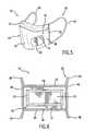
- FIG. 5is a perspective view of an exemplary embodiment of a face mask.
- the absorbent elementis located on both the outer and inner surfaces of the body portion.
- FIG. 6is a back view of an exemplary embodiment of a face mask.
- the absorbent elementis located on the inner surface of the body portion and forms a perimeter bounding an area of the inner surface.
- FIG. 7is a back view of an exemplary embodiment of a face mask.
- the absorbent elementis located around the perimeter of the inner surface of the body portion.
- nonwoven fabric or webmeans a web having a structure of individual fibers or threads which are interlaid, but not in an identifiable manner as in a knitted fabric.
- Nonwoven fabrics or webshave been formed from various processes such as, for example, meltblowing processes, spunbonding processes, and bonded carded web processes.
- the basis weight of nonwoven fabricsis usually expressed in ounces of material per square yard (osy) or grams per square meter (gsm) and the fiber diameters are usually expressed in microns. (Note that to convert from osy to gsm, multiply osy by 33.91).
- ultrasonic bondingrefers to a process in which materials (fibers, webs, films, etc.) are joined by passing the materials between a sonic horn and anvil roll.
- materialsfibers, webs, films, etc.
- An example of such a processis illustrated in U.S. Pat. No. 4,374,888 to Bornslaeger, the entire contents of which are incorporated herein by reference in their entirety for all purposes.
- thermal point bondinginvolves passing materials (fibers, webs, films, etc.) to be bonded between a heated calender roll and a heated anvil roll.
- the calender rollis usually, though not always, engraved with a pattern in some way such that the entire fabric is not bonded across its entire surface.
- the surface of the anvil rollis usually flat and/or smooth.
- various patterns for calender rollshave been developed for functional as well as aesthetic reasons.
- the percent bonding areavaries from around 10 percent to around 30 percent of the area of the fabric laminate.
- the bonded areasare typically discrete points or shapes and not interconnected.
- thermal point bondingholds the laminate layers together and imparts integrity and strength to the nonwoven material by bonding filaments and/or fibers together thereby limiting their movement.
- thermal pattern bondinginvolves passing materials (fibers, webs, films, etc.) to be bonded between a heated calender roll and an anvil roll as with thermal point bonding. The difference is that the bonded areas are interconnected producing discrete areas of unbonded fibers.
- Various patterns for calender rollshave been developed for functional as well as aesthetic reasons.
- the percent bonding areavaries from around 10 percent to around 30 percent of the area of the fabric laminate.
- the term “electret” or “electret treating”refers to a treatment that imparts a charge to a dielectric material, such as a polyolefin.
- the chargeincludes layers of positive or negative charges trapped at or near the surface of the polymer, or charge clouds stored in the bulk of the polymer.
- the chargealso includes polarization charges which are frozen in alignment of the dipoles of the molecules.
- Methods of subjecting a material to electret treatingare well known by those skilled in the art. These methods include, for example, thermal, liquid-contact, electron beam, and corona discharge methods.
- One particular technique of subjecting a material to electret treatingis disclosed in U.S. Pat. No. 5,401,466 to Foltz, the entire contents of which are herein incorporated by reference in their entirety for all purposes. This technique involves subjecting a material to a pair of electrical fields wherein the electrical fields have opposite polarities.
- spunbonded fibersrefers to small diameter fibers which are formed by extruding molten thermoplastic material as filaments from a plurality of fine, usually circular capillaries of a spinneret with the diameter of the extruded filaments then being rapidly reduced to fibers as by, for example, in U.S. Pat. No. 4,340,563 to Appel et al., and U.S. Pat. No. 3,692,618 to Dorschner et al., U.S. Pat. No. 3,802,817 to Matsuki et al., U.S. Pat. Nos. 3,338,992 and 3,341,394 to Kinney, U.S. Pat. No.
- Spunbond fibersare generally continuous and have diameters generally greater than about 7 microns, more particularly, between about 10 and about 40 microns.
- meltblown fibersmeans fibers formed by extruding a molten thermoplastic material through a plurality of fine, usually circular, die capillaries as molten threads or filaments into converging high velocity, usually hot, gas (e.g. air) streams which attenuate the filaments of molten thermoplastic material to reduce their diameter, which may be to microfiber diameter. Thereafter, the meltblown fibers are carried by the high velocity gas stream and are deposited on a collecting surface to form a web of randomly disbursed meltblown fibers.
- gase.g. air
- stretch bonded laminaterefers to a composite material having at least two layers in which one layer is a gatherable layer and the other layer is an elastic layer. The layers are joined together when the elastic layer is extended from its original condition so that upon relaxing the layers, the gatherable layer is gathered.
- Such a multilayer composite elastic materialmay be stretched to the extent that the nonelastic material gathered between the bond locations allows the elastic material to elongate.
- One type of stretch bonded laminateis disclosed, for example, by U.S. Pat. No. 4,720,415 to Vander Wielen et al., the entire contents of which are incorporated herein by reference in their entirety for all purposes.
- Other composite elastic materialsare disclosed in U.S. Pat. No.
- neckingor “neck stretching” interchangeably refer to a method of elongating a nonwoven fabric, generally in the machine direction, to reduce its width (cross-machine direction) in a controlled manner to a desired amount.
- the controlled stretchingmay take place under cool, room temperature or greater temperatures and is limited to an increase in overall dimension in the direction being stretched up to the elongation required to break the fabric, which in most cases is about 1.2 to 1.6 times.
- the webretracts toward, but does not return to, its original dimensions.
- necked materialrefers to any material which has undergone a necking or neck stretching process.
- reversibly necked materialrefers to a material that possesses stretch and recovery characteristics formed by necking a material, then heating the necked material, and cooling the material. Such a process is disclosed in U.S. Pat. No. 4,965,122 to Morman, the entire contents of which are incorporated herein by reference in their entirety for all purposes.
- neck bonded laminaterefers to a composite material having at least two layers in which one layer is a necked, non-elastic layer and the other layer is an elastic layer. The layers are joined together when the non-elastic layer is in an extended (necked) condition.
- neck-bonded laminatesare such as those described in U.S. Pat. Nos. 5,226,992, 4,981,747, 4,965,122 and 5,336,545 to Morman, the entire contents of which are incorporated herein by reference in their entirety for all purposes.
- meltblown materialmeans a meltblown material to which at least one other material is added during the meltblown material formation.
- the meltblown materialmay be made of various polymers, including elastomeric polymers.
- additional materialsmay be added to the meltblown fibers during formation, including, for example, pulp, superabsorbent particles, cellulose or staple fibers.
- Coform processesare illustrated in commonly assigned U.S. Pat. No. 4,818,464 to Lau and U.S. Pat. No. 4,100,324 to Anderson et al., the entire contents of which are incorporated herein by reference in their entirety for all purposes.
- switchbondedrefers to a process in which materials (fibers, webs, films, etc.) are joined by stitches sewn or knitted through the materials. Examples of such processes are illustrated in U.S. Pat. No. 4,891,957 to Strack et al. and U.S. Pat. No. 4,631,933 to Carey, Jr., the entire contents of which are incorporated herein by reference in their entirety for all purposes.
- the term “elastic”refers to any material, including a film, fiber, nonwoven web, or combination thereof, which upon application of a biasing force, is stretchable to a stretched, biased length which is at least about 150 percent, or one and a half times, its relaxed, unstretched length, and which will recover at least 15 percent of its elongation upon release of the stretching, biasing force.
- Extensible and retractablerefers to the ability of a material to extend upon stretch and retract upon release. Extensible and retractable materials are those which, upon application of a biasing force, are stretchable to a stretched, biased length and which will recover a portion, preferably at least about 15 percent, of their elongation upon release of the stretching, biasing force.
- elastomeror “elastomeric” refer to polymeric materials that have properties of stretchability and recovery.
- the term “stretch”refers to the ability of a material to extend upon application of a biasing force. Percent stretch is the difference between the initial dimension of a material and that same dimension after the material has been stretched or extended following the application of a biasing force. Percent stretch may be expressed as [(stretched length B initial sample length)/initial sample length] ⁇ 100. For example, if a material having an initial length of one (1) inch is stretched 0.50 inch, that is, to an extended length of 1.50 inches, the material can be said to have a stretch of 50 percent.
- the term “recover” or “recovery”refers to a contraction of a stretched material upon termination of a biasing force following stretching of the material by application of the biasing force. For example, if a material having a relaxed, unbiased length of one (1) inch is elongated 50 percent by stretching to a length of one and one half (1.5) inches the material would have a stretched length that is 150 percent of its relaxed length. If this exemplary stretched material contracted, that is recovered to a length of one and one tenth (1.1) inches after release of the biasing and stretching force, the material would have recovered 80 percent (0.4 inch) of its elongation.
- compositerefers to a material which may be a multicomponent material or a multilayer material. These materials may include, for example, spunbond-meltblown-spunbond, stretch bonded laminates, neck bonded laminates, or any combination thereof.
- polymergenerally includes but is not limited to, homopolymers, copolymers, such as for example, block, graft, random and alternating copolymers, terpolymers, etc. and blends and modifications thereof. Furthermore, unless otherwise specifically limited, the term “polymer” shall include all possible geometrical configurations of the molecule. These configurations include, but are not limited to isotactic, syndiotactic and random symmetries.
- ranges and limits mentioned hereininclude all ranges located within, and also all values located under or above the prescribed limits. Also, all ranges mentioned herein include all subranges included in the mentioned ranges. For instance, a range from 100-200 also includes ranges from 110-150, 170-190, and 153-162. Further, all limits mentioned herein include all other limits included in the mentioned limit. For example, a limit of up to about 7 also includes a limit of up to about 5, up to about 3, and up to about 4.5.
- One exemplary embodimentprovides for a face mask 10 that has a body portion 12 with an outer surface 16 and an oppositely disposed inner surface 18 .
- An absorbent element 22is located on at least one of the surfaces 16 or 18 .
- the absorbent element 22is capable of absorbing at least 3.5 grams of water so as to capture moisture vapor and/or condensation due to human respiration and perspiration so as to reduce or eliminate fogging of eye wear such as eye wear and or a face shield that may be worn.
- the absorbent element 22may be capable of absorbing between 3.7 and 5.9 grams of water in accordance with various exemplary embodiments. Any amount or range greater than or equal to 3.5 grams of water may be employed in accordance with other exemplary embodiments.
- the absorbent element 22may be capable of absorbing greater than 5 grams of water, greater than 7 grams of water, greater than 10 grams of water, greater than 15 grams of water, greater than 20 gram of water, greater than 25 gra ms of water, between 5 and 15 grams of water, between 3.5 and 50.5 grams of water, between 3.7 and 4.3 grams of water, or 8 grams of water in accordance with various exemplary embodiments.
- the absorbent element 22may be capable of absorbing between 3.5 and 6.0 grams of water per gram of fiber of the absorbent element 22 in certain exemplary embodiments. In certain exemplary embodiments, the water capacity of the absorbent member 22 may be between 350-600%. Further, the absorbent element 22 may be capable of absorbing between 3.7 and 4.3 grams of water in an amount of time between 1.25 and 1.6 seconds in certain exemplary embodiments.
- FIG. 1is a perspective view of the face mask 10 in accordance with one exemplary embodiment.
- the face mask 10includes a body portion 12 that has an inner surface 18 that is configured for facing and contacting the face of a user 14 ( FIG. 2 ) when the face mask 10 is worn.
- the absorbent element 22is shown as a horizontal strip of material that is attached to the upper edge of the inner surface 18 .
- the absorbent element 22is attached to the inner surface 18 of the body portion 12 in any manner as is commonly known to one having ordinary skill in the art.
- the absorbent element 22may be attached to the inner surface 18 through ultrasonic bonding, adhesion, and/or through mechanical fasteners such as staples in accordance with various exemplary embodiments.
- the absorbent element 22may be a separate external component attached to the body portion 12 . Additionally, it is to be understood that the absorbent element 22 need not be a separate element that is attached to the inner surface 18 of the body portion 12 in accordance with other exemplary embodiments.
- the absorbent element 22may be an area of the body portion 12 that is treated or otherwise manufactured so as to have the desired absorbent properties.
- FIG. 2is a perspective view of the face mask 10 of FIG. 1 shown attached to the face of the user 14 .
- the absorbent element 22acts to absorb moisture and/or condensation from respiration or perspiration of the user 14 . Aside from reducing or eliminating fogging on eye wear that may be worn by the user 14 , the absorbent element 22 may also act to reduce and/or eliminate condensation that may accumulate on the face of the user 14 and potentially result in irritation of the user 14 .
- FIG. 3shows the inner surface 18 of the body portion 12 of an exemplary embodiment of the face mask 10 .
- the absorbent element 22is a strip of material that is located across the entire horizontal length 24 of the body portion 12 . When placed onto the user 14 ( FIG. 2 ) the absorbent element 22 contacts the nose and cheeks of the user 14 and absorbs moisture and/or condensation in this location.
- the body portion 12is provided with a plurality of folds 28 that extend across the horizontal length 24 .
- the folds 28may be opened by the user 14 so as to adjust the size of the body portion 12 in the vertical length 26 .
- the folds 28allow for adjustment of the body portion 12 so as to allow for a better fit on the face of the user 14 and formation of a breathing chamber.
- the body portion 12may form a breathing chamber with the perimeter of the chamber sealing to the face of the user 14 in certain exemplary embodiment.
- the folds 28may extend only part way across the body portion 12 in accordance with various exemplary embodiments.
- the folds 28may be provided in any number and may be oriented at any angle on the body portion 12 .
- the folds 28may run at a 45° angle to the horizontal length 24 .
- the folds 28may run along the vertical length 26 of the body portion 12 . It is to be understood, however, that folds 28 are not present in accordance with other exemplary embodiments.
- Bindings 48 and 50may act to limit the vertical extension of the edges of the body portion 12 when the folds 28 are unfolded. As such, bindings 48 and 50 may be present in order to help provide for a desired shape of the body portion 12 . Additionally, bindings 52 and 54 may also act to limit extension of the edges of the body portion 12 when folds 28 are unfolded. This may also be the case if folds 28 are provided in orientations along both the horizontal and vertical lengths 24 and 26 of the body portion 12 . As such, bindings 52 and 54 may also be employed in order to achieve a desired shape of the body portion 12 .
- the folds 28 in the body portion 12may be of any type commonly known to those having ordinary skill in the art.
- the side edges of the layers 32 , 34 and 36may be held together by any method commonly known to one having ordinary skill in the art.
- staples or adhesionmay be used to hold the layers 32 , 34 and 36 together.
- ultrasonic bondingas represented by ultrasonic bond dimples 46 , may be used in order to hold the layers 32 , 34 and 36 together. It is to be understood that other ultrasonic bonding patterns may be employed to facilitate holding of the layers 32 , 34 and 36 to one another.
- FIG. 3shows bindings 48 and 50 on either side of the body portion 12 used in order to constrain unfolding of the layers 32 , 34 and 36 .
- binding 52may be located on the top edge of the body portion 12 and binding 54 may be located on the bottom edge of the body portion 12 .
- the bindings 48 , 50 , 52 and 54may be of any type commonly known to one having ordinary skill in the art. Bindings 48 , 50 , 52 and 54 act to secure the absorbent element 22 to the body portion 12 in accordance with various exemplary embodiments.
- the absorbent element 22may additionally act to seal the periphery of the upper edge of the body portion 12 so that warm, moist exhaled breath cannot be directed therethrough.
- the absorbent element 22may be configured structurally as that shown in U.S. Pat. No. 6,520,181 to Baumann, et al., the entire contents of which are incorporated herein by reference in their entirety for all purposes.
- the absorbent element 22need not be configured as a seal in other exemplary embodiments.
- FIG. 4A front view that shows the outer surface 16 of the body portion 12 of face mask 10 in accordance with another exemplary embodiment is shown in FIG. 4 .
- the absorbent element 22is a separate piece of material that is located on the top edge of the body portion 12 and attached to the outer surface 16 instead of the inner surface 18 as shown in FIGS. 1-3 .
- Placement on the outer surface 16may be more effective as the absorbent element 22 may actually contact a face shield worn by the user 14 ( FIG. 2 ) and draw moisture and condensation therefrom.
- placement on the outer surface 16may also be advantageous in the fact that the absorbent element 22 may be closer to the eye wear worn by the user 14 and may not have material of the body portion 12 located between the absorbent element 22 and the eye wear worn by the user 14 .
- This type of an arrangementmay be advantageous in that moisture and/or condensation may be more easily absorbed by the absorbent element 22 .
- placement of the absorbent element 22 on the inner surface 18is more advantageous in that the absorbent element 22 may or may not be closer to the eye wear worn by the user 14 and it is desirable to have additional material between the absorbent element 22 and the eye wear worn by the user 14 .
- FIG. 5shows an alternative exemplary embodiment of the face mask 10 in which the absorbent element 22 is located on both the outer surface 16 and the inner surface 18 of the body portion 12 .
- the absorbent element 22is shown located on the upper edge of the body portion 12 . It is to be understood, however, that in accordance with other exemplary embodiments that the absorbent element 22 is located at any location on the outer surface 16 and/or the inner surface 18 . For instance, the absorbent element 22 may be located on the entire outer surface 16 and/or on the entire inner surface 18 . Additionally, the absorbent element 22 may be located on the bottom edge of the body portion 12 as opposed to the top edge of the body portion 12 as shown in FIGS. 1-5 .
- the absorbent element 22may be variously shaped in accordance with other exemplary embodiments.
- the absorbent element 22may be disc shaped, star shaped, triangular shaped and/or square shaped in accordance with various exemplary embodiments.
- Various exemplary embodimentsare therefore included in which the absorbent element 22 is located at one or more locations on the outer surface 16 and/or the inner surface 18 and configured in any shape or pattern as is commonly known to one having ordinary skill in the art.
- the body portion 12is shown as being made of a plurality of layers 32 , 34 and 36 .
- Layer 32may be an inner layer of the body portion 12 and have the inner surface 18 defined thereon.
- Layer 36may be an outer layer of the body portion 12 and have the outer surface 16 defined thereon.
- layer 34may be an intermediate layer located between the layers 32 and 36 .
- the body portion 12may be made of any number of layers in accordance with various exemplary embodiments.
- the body portion 12can be made of a single layer in accordance with one exemplary embodiment.
- the body portion 12can be made of three layers, five layers, seven layers, ten or fifteen layers in accordance with various exemplary embodiments.
- FIG. 6shows an exemplary embodiment of the face mask 10 in which the absorbent element 22 is located on the inner surface 18 of the body portion 12 .
- the absorbent element 22is configured on the inner surface 18 so as to surround an area 30 of the inner surface 18 .
- the area 30is the portion of the inner surface 18 proximate to the mouth or nostrils of the user 14 ( FIG. 2 ).
- the absorbent element 22surrounds the mouth and nostrils of the user 14 and absorbs moisture and/or condensation therefrom in order to prevent fogging of eye wear worn by the user 14 .
- FIG. 7is an exemplary embodiment of the face mask 10 in which the absorbent element 22 surrounds the entire perimeter of the body portion 12 .
- the absorbent element 22may surround the perimeter of the outer surface 16 in accordance with other exemplary embodiments.
- the face mask 10may be configured so as to have the absorbent element 22 located around the perimeter of the body portion 12 on both the outer surface 16 and inner surface 18 of the body portion 12 .
- other exemplary embodimentsexist in which the absorbent element 22 surrounds most of, but not all of, the perimeter of the body portion 12 .
- the absorbent element 22may also be configured so as to be a seal in order to prevent moisture and/or condensation from traveling from the inside of the face mask 10 to the eye wear worn by the user 14 .
- the absorbent element 22may be configured so as to seal one or more edges of the body portion 12 .
- the exemplary embodiments shown in FIGS. 6 and 7may be configured so that the absorbent element 22 is a seal. As such, in FIG. 6 the absorbent element 22 may act to prevent moisture and/or condensation from escaping the area 30 while in the exemplary embodiment of FIG. 7 the absorbent element 22 may act to prevent moisture and/or condensation from traveling past the perimeter of the inner surface 18 of the body portion 12 .
- the absorbent element 22may be configured as a seal as that disclosed in U.S. Pat. No. 6,062,220 to Whitaker, et al., the entire contents of which are incorporated herein by reference in their entirety for all purposes. Additionally or alternatively, the absorbent element 22 may be configured so as to be only a partial seal. In this regard, the absorbent element 22 may act as a seal to prevent some of, but not all of, the moisture and/or condensation from traveling between the absorbent element 22 and the face of the user 14 . It is to be understood, however, that in accordance with other exemplary embodiments that the absorbent element 22 is not configured as a seal. In this regard, the absorbent element 22 contacts the face of the user 14 but does not form a seal therewith. It is to be understood that various exemplary embodiments exist in which the absorbent element 22 may or may not prevent fogging through sealing action.
- the absorbent element 22may be added to any type of face mask 10 .
- the absorbent element 22may reduce fogging by absorbing moisture and/or condensation by exhaled air or perspiration of the user 14 ( FIG. 2 ) and may or may not reduce fogging by acting as a sealing element.
- the absorbent element 22may be made of a material that is naturally absorbent.
- the absorbent element 22may be made of a material that includes cellulosic fibers.
- the absorbent element 22is a wet laid material. Further exemplary embodiments exist in which the absorbent element 22 is a urethane foam, a cellulosic sponge, a urethane film, and/or a urethane non-woven material.
- the absorbent element 22is made of any number of materials and is not limited to being made of a single material.
- the absorbent element 22is made of a HYDROKNIT® material as manufactured by Kimberly-Clark Worldwide, Inc. having offices located at 401 North Lake Street, Neenah, Wis., 54957.
- a hydroknit materialis a hydrophilic material manufactured using jets of water in order to bond soft absorbent paper fibers to strong polypropylene non-woven fabric.
- the absorbent element 22may be made of a hydrophobic material, such as polypropylene, and treated so as to achieve a desired absorbency.
- the absorbent element 22may be a hydrophobic foam that is treated so as to be hydrophilic in order to achieve a desired absorbency.
- the absorbent element 22is initially a hydrophilic material, or a hydrophobic material that is treated so as to be capable of achieving a desired degree of absorbency.
- the absorbent element 22is a material that is treated with a surfactant to as to increase the hydrophilic property of the absorbent element 22 so that the absorbent element 22 is more liquid absorbent.
- the absorbent element 22is any type or types of materials that are treated with surfactant based chemistry so as to have increase absorbency.
- the absorbent element 22is a single type of material in accordance with various exemplary embodiments.
- the absorbent element 22is made of multiple types of materials in other exemplary embodiments.
- the absorbent element 22may be a laminate made of two or more layers of different materials in accordance with various exemplary embodiments.
- the absorbent element 22is a laminate that is formed from a film and a polyurethane foam.
- the laminateay be treated with a surfactant such as Gemtex 33 manufactured by FINETEX®, Inc. located at 418 Falmouth Avenue, P.O. Box 216, Elmwood Park, N.J. 07407.
- the film layer of the laminate making up the absorbent element 22is attached to the inner surface 18 and the polyurethane foam layer is located on top of the film and in contact with the face of the user 14 when worn.
- the absorbent element 22is a spunbound, meltblown material.
- the spunbound, meltblown materialis treated with a surfactant such as MASIL®, manufactured by BASF® Corporation located at 3000 Continental Drive North, Mount Olive, N.J. 07828, so as to have an increased absorbency.
- a surfactantsuch as E-230 FQ Bermocoll manufactured by Akzo Nobel Cellulosic Specialties located at 99 Hewley Lane, Stratford, Conn. 06614, may be used so as to enhance the absorbency of the material making up the absorbent element 22 .
- various exemplary embodimentsare included in which the absorbent element 22 is made of one or more types of materials and one or more surfactants.
- exemplary embodimentsexist in which the absorbent element 22 is made of only one or more materials without one or more surfactants present.
- the absorbent element 22is a spunbond film laminate that is treated with a surfactant such as DOSS70D which is manufactured by manufacturers Chemicals, L.P., located at 4325 Old Tasso Road, P.O. Box 2788, Cleveland, Tenn. 37312.
- a surfactantsuch as DOSS70D which is manufactured by manufacturers Chemicals, L.P., located at 4325 Old Tasso Road, P.O. Box 2788, Cleveland, Tenn. 37312.
- the absorbent element 22may be made of a material as is commonly known to one have ordinary skill in the art.
- the absorbent element 22may be made of a material or materials such as those disclosed in U.S. Pat. No. 6,520,181 to Baumann, et al., the entire contents of which are incorporated herein by reference in their entirety for all purposes. However, it is to be understood that the absorbent element 22 used may be selected or treated so as to be capable of absorbing at least 3.5 grams of water.
- the body portion 12can be of a variety of styles and geometries, such as, but not limited to, flat half masks, pleated face masks, cone masks, duckbill style masks, trapezoidally shaped masks, etc.
- the styles shown in the Figuresare for illustrative purposes only.
- the body portion 12may be configured as that shown in U.S. Pat. No. 6,484,722 to Bostock, et al., the entire contents of which are incorporated by reference herein in their entirety for all purposes.
- the face mask 10may isolate the mouth and the nose of the user 14 from the environment.
- the face mask 10may be attached to the user 14 by a fastening member 20 that may be a pair of manual tie straps 38 that are wrapped around the head of the user 14 (and a hair cap 42 if worn by the user 14 ) and are connected to one another. It is to be understood, however, that other types of fastening members 20 are employed in accordance with various exemplary embodiments.
- the face mask 10may be attached to the user 14 by a fastening member 20 that may be ear loops 40 ( FIG. 5 ), elastic bands wrapped around the head of the user 14 , a hook and loop type fastener arrangement, or a connection directly attaching the face mask 10 to the hair cap 42 .
- the configuration of the face mask 10is different in accordance with various exemplary embodiments.
- the face mask 10can be made in order to cover both the eyes, hair, nose, throat, and mouth of the user 14 .
- the present inventionincludes face masks 10 that cover areas above and beyond simply the nose and mouth of the user 14 .
- the face mask 10may also incorporate any combination of known face mask 10 features, such as visors or shields, sealing films, beard covers, etc. Exemplary face masks and features incorporated into face masks are described and shown, for example, in the following U.S. Patents: U.S. Pat. Nos.
- the exemplary embodiment shown in FIG. 7includes a series of structural elements (stays) 44 incorporated into the body portion 12 in order to provide for a face mask 10 with different desired characteristics.
- the stays 44provide for structural rigidity of the body portion 12 , and may also be shaped in order to help seal the periphery of the body portion 12 .
- a stay 44may be employed within the body portion 12 in order to help conform the body portion 12 around the nose of the user 14 ( FIG. 2 ).
- the stay or stays 52may be used to help seal the perimeter of the body portion 12 around the face of the user 14 and/or to help maintain the shape of a breathing chamber and to keep the breathing chamber from the face of the user 14 .
- a stay 44may be employed in order to better shape the body portion 12 around the chin of the user 14 ( FIG. 2 ).
- the stays 44may allow for a better fit of the body portion 12 and may be used to help form a chamber around the mouth and/or nose of the user 14 .
- the stays 44may help achieve a better fit so as to prevent the transfer of pathogens through any possible openings along the perimeter of the body portion 12 .
- a series of stays 44 incorporated into a face mask 10is disclosed in U.S. Pat. No. 5,699,791, to Sukiennik et al., the entire contents of which are incorporated herein by reference in their entirety for all purposes.
- Stays 44may be made of an elongated malleable member such as a metal wire or an aluminum band that can be formed into a rigid shape in order to impart this shape into the body portion 12 of the face mask 10 .
- a metal wire or an aluminum bandthat can be formed into a rigid shape in order to impart this shape into the body portion 12 of the face mask 10 .
- various exemplary embodimentsexist that do not include stays 44 .
- the intermediate layer 34may be a filtration media configured to prevent the passage of pathogens through the body portion 12 while still allowing for the passage of air in order to permit the user 14 ( FIG. 2 ) to breath.
- the layers 32 , 34 and 36may be configured so that any of the layers 32 , 34 and 36 include filtration media.
- both of the layers 32 and 36may include filtration media in accordance with one exemplary embodiment.
- the layers 32 , 34 and 36may be constructed from various materials known to those skilled in the art.
- the layer 36 of the body portion 12may be any nonwoven web, such as a spunbonded, meltblown, or coform nonwoven web, a bonded carded web, or a wetlaid composite.
- the layer 36 of the body portion 12 and layer 32may be a necked nonwoven web or a reversibly necked nonwoven web.
- the layers 32 , 34 and 36may be made of the same material or of different materials.
- polyethylenessuch as Dow Chemical's ASPUN® 6811A linear polyethylene, 2553 LLDPE and 25355, and 12350 polyethylene are such suitable polymers.
- Fiber forming polypropylenesinclude, for example, Exxon Chemical Company's Escorene® PD 3445 polypropylene and Basell's PF-304.
- Many other suitable polyolefinsare commercially available as are known to those having ordinary skill in the art.
- the various materials used in construction of the face mask 10may include a necked nonwoven web, a reversibly necked nonwoven material, a neck bonded laminate, and elastic materials such as an elastic coform material, an elastic meltblown nonwoven web, a plurality of elastic filaments, an elastic film, or a combination thereof.
- elastic materialshave been incorporated into composites, for example, in U.S. Pat. No. 5,681,645 to Strack et al., U.S. Pat. No. 5,493,753 to Levy et al., U.S. Pat. No. 4,100,324 to Anderson et al., and in U.S. Pat. No.
- the filmmay be sufficiently perforated to ensure that the user 14 ( FIG. 2 ) can breathe through the body portion 12 if the face mask 10 is desired to be breathable in this location.
- the intermediate layer 34 when configured as a filtration layermay be a meltblown nonwoven web and, in some embodiments, is electret treated.
- Electret treatmentresults in a charge being applied to the intermediate layer 34 that further increases filtration efficiency by drawing particles to be filtered toward the intermediate layer 34 by virtue of their electrical charge.
- Electret treatmentcan be carried out by a number of different techniques. One technique is described in U.S. Pat. No. 5,401,446 to Tsai et al., the entire contents of which are incorporated herein by reference in their entirety for all purposes. Other methods of electret treatment are known in the art, such as that described in U.S. Pat. No. 4,215,682 to Kubik et al.; U.S. Pat. No.
- the intermediate layer 34may be made of an expanded polytetrafluoroethylene (PTFE) membrane, such as those manufactured by W. L. Gore & Associates. A more complete description of the construction and operation of such materials can be found in U.S. Pat. Nos. 3,953,566 and 4,187,390 to Gore, the entire contents of these patents are incorporated herein by reference in their entirety for all purposes.
- PTFEpolytetrafluoroethylene
- the expanded polytetrafluoroethylene membranemay be incorporated into a multi-layer composite, including, but not limited to, an outer nonwoven web layer 36 , an extensible and retractable layer, and an inner layer 32 comprising a nonwoven web.
- SMSmay be used to comprise the layers 32 , 34 and 36 .
- SMSis a material that is made of meltblown fibers between two spunbond layers made of spunbonded fibers.
- Multiple layers of the face mask 10may be joined by various methods, including adhesive bonding, thermal point bonding, or ultrasonic bonding. Although shown as having three layers 32 , 34 and 36 , it is to be understood that in other exemplary embodiments of the present invention, that the body portion 12 and/or the entire face mask 10 may be made of any number of layers.
- the body portion 12 of the face mask 10may be made of inelastic materials.
- the material used to construct the body portion 12may be comprised of elastic materials, allowing for the body portion 12 to be stretched over the nose, mouth, and/or face of the user 14 .
- the face mask 10 of the present inventionmay be made of an elastic material that allows the face mask 10 to stretch in one or more directions.
- the use of an elastic material incorporated into the body portion 12may allow for fuller coverage of the user's 14 face and provide for more flexibility in accommodating variously sized faces of the users 14 .
- the body portion 12may be made of an inelastic material. As such, the material that makes up the face mask 10 may exhibit elastic or inelastic characteristics depending upon the user's 14 needs.
- the body portion 12 of the face mask 10may be configured so that it is capable of stretching across the face of the user 14 ( FIG. 2 ) from ear to ear and/or nose to chin.
- the ability of the body portion 12 to stretch and recovermay provide the face mask 10 with better sealing capabilities and a more comfortable fit than face masks 10 that have an inelastic body portion 12 .
- the body portion 12may have at least one layer or a material that has stretch and recovery properties.
- the entire face mask 10may be composed of a material that has stretch and recovery properties in other exemplary embodiments.
- the percent recoveryis about 15% and the percent stretch is between about 15-65%, in other embodiments the percent recovery is between about 20-40% stretch, and in still other embodiments the percent recovery is between about 25-30% stretch.
- Elastomeric thermoplastic polymersmay be used in the face mask 10 and may include block copolymers having the general formula A-B-A′ or A-B, where A and A′ are each a thermoplastic polymer endblock which contains a styrenic moiety such as a poly (vinyl arene) and where B is an elastomeric polymer midblock such as a conjugated diene or a lower alkene polymer.
- Block copolymers of the A-B-A′ typecan have different or the same thermoplastic block polymers for the A and A′ blocks, and the present block copolymers are intended to embrace linear, branched and radial block copolymers.
- elastomeric resinsexamples include those made from block copolymers such as polyurethanes, copolyether esters, polyamide polyether block copolymers, ethylene vinyl acetates (EVA), block copolymers having the general formula A-B-A′ or A-B like copoly(styrene/ethylene-butylene), styrene-poly(ethylene-propylene)-styrene, styrene-poly(ethylene-butylene)-styrene, (polystyrene/poly(ethylene-butylene)/polystyrene, poly(styrene/ethylene-butylene/styrene) and the like.
- block copolymerssuch as polyurethanes, copolyether esters, polyamide polyether block copolymers, ethylene vinyl acetates (EVA), block copolymers having the general formula A-B-A′ or A-B like copoly(s
- One or more layers 32 , 34 and 36 of the face mask 10may be made of a composite that is a neck bonded laminate in certain exemplary embodiments.
- the neck bonded laminatemay utilize a necked material or a reversibly necked material.
- the necking processtypically involves unwinding a material from a supply roll and passing it through a brake nip roll assembly at a given linear speed.
- a take-up roll or nipoperating at a linear speed greater than that of the brake nip roll, draws the material and generates the tension needed to elongate and neck the fabric.
- the stretched materialis heated and cooled while in a stretched condition.
- the heating and cooling of the stretched materialcauses additional crystallization of the polymer and imparts a heat set.
- the necked material or reversibly necked materialis then bonded to an elastic material. Afterwards, the layer may be folded in order to form folds 28 .
- the resulting necked compositeis extensible and retractable in the cross-machine direction, that is the direction perpendicular to the direction the material is moving when it is produced. Upon extension and release, the elastic material provides the force needed for the extended composite to retract.
- the composite making up one or more of the layers 32 , 34 and 36may be a stretch bonded laminate.
- a stretch bonded laminateis formed by providing an elastic material, such as a nonwoven web, filaments, or film, extending the elastic material, attaching it to a gatherable material, and releasing the resulting laminate.
- a stretch bonded laminateis extensible and retractable in the machine direction, that is the direction that the material is moving when it is produced.
- a composite with multiple layersmay be formed by providing the elastic layer and the gatherable layers, and subjecting it to this process either simultaneously or stepwise.
- the stretch bonded laminatemay also include a necked material that is extensible and retractable in the cross-direction such that the overall laminate is extensible and retractable in at least two dimensions.
- an elastomeric meltblown nonwoven webis provided, the elastomeric meltblown nonwoven web is then extended in the machine direction, and the necked spunbonded nonwoven material is attached to the elastomeric meltblown nonwoven web by thermal bonding while the elastomeric meltblown web is extended.
- the resulting compositeis extensible and retractable in both the cross-direction and machine direction, due to the extensibility of the necked material and the use of the stretch bonding process, respectively.
- the compositemay then be folded in order to form folds 28 and attached to or otherwise incorporated with one or more layers to make up the body portion 12 .
- the compositemay contain various chemical additives or topical chemical treatments in or on one or more layers, including, but not limited to, surfactants, colorants, antistatic chemicals, antifogging chemicals, fluorochemical blood or alcohol repellents, lubricants, or antimicrobial treatments.
- a face mask 10 that included an absorbent element 22 in the form of an absorbent foamwas attached to a breathing mannequin head.
- the breathing mannequin headexhaled warm, moist air in order to simulate human respiration. Eye wear was placed on the mannequin and the performance of the face mask was evaluated.
- the absorbent element 22was found to successfully absorb moisture exhaled by the mannequin.
- the absorbent element 22was an absorbent foam material.
- a face mask 10was also provided with an absorbent element 22 that was an absorbent laminate.
- the face mask 10was applied to the head of a mannequin capable of exhaling warm, moist air in order to simulate human respiration. Eye wear were placed on the mannequin and the performance of the face mask 10 was evaluated.
- the absorbent laminate making up the absorbent element 22was found to successfully redirect airflow away from the eye wear resulting in fewer incidences of fogging, and the absorbent element 22 was found to successfully absorb moisture from the exhaled air of the mannequin.
Landscapes
- Health & Medical Sciences (AREA)
- General Health & Medical Sciences (AREA)
- Physical Education & Sports Medicine (AREA)
- Engineering & Computer Science (AREA)
- Textile Engineering (AREA)
- Respiratory Apparatuses And Protective Means (AREA)
Abstract
Description
Claims (9)
Priority Applications (1)
| Application Number | Priority Date | Filing Date | Title |
|---|---|---|---|
| US11/022,379US8622059B2 (en) | 2004-12-21 | 2004-12-21 | Face mask with absorbent element |
Applications Claiming Priority (1)
| Application Number | Priority Date | Filing Date | Title |
|---|---|---|---|
| US11/022,379US8622059B2 (en) | 2004-12-21 | 2004-12-21 | Face mask with absorbent element |
Publications (2)
| Publication Number | Publication Date |
|---|---|
| US20060130842A1 US20060130842A1 (en) | 2006-06-22 |
| US8622059B2true US8622059B2 (en) | 2014-01-07 |
Family
ID=36594165
Family Applications (1)
| Application Number | Title | Priority Date | Filing Date |
|---|---|---|---|
| US11/022,379Expired - Fee RelatedUS8622059B2 (en) | 2004-12-21 | 2004-12-21 | Face mask with absorbent element |
Country Status (1)
| Country | Link |
|---|---|
| US (1) | US8622059B2 (en) |
Cited By (19)
| Publication number | Priority date | Publication date | Assignee | Title |
|---|---|---|---|---|
| US20140326245A1 (en)* | 2013-05-06 | 2014-11-06 | Mei-Sheng Teng | Medical Face Mask with Sealing Strip |
| US20180353781A1 (en)* | 2015-12-03 | 2018-12-13 | Honeywell International Inc. | Annular unit for moisture management in respiratory mask |
| USD849928S1 (en)* | 2017-05-15 | 2019-05-28 | Jonathan Grover | Facemask |
| USD866869S1 (en) | 2017-02-07 | 2019-11-12 | Medline Industries, Inc. | Face mask |
| US10835704B1 (en) | 2019-05-15 | 2020-11-17 | Applied Research Associates, Inc. | Reusable respiratory protection device |
| US10960238B1 (en) | 2020-07-23 | 2021-03-30 | Samuel Reele | Face mask |
| US20220134144A1 (en)* | 2020-11-03 | 2022-05-05 | Marcello Massimiliano BALESTRA | Face protection mask |
| US11413481B2 (en) | 2015-05-12 | 2022-08-16 | 3M Innovative Properties Company | Respirator tab |
| US11690767B2 (en) | 2014-08-26 | 2023-07-04 | Curt G. Joa, Inc. | Apparatus and methods for securing elastic to a carrier web |
| US11701268B2 (en) | 2018-01-29 | 2023-07-18 | Curt G. Joa, Inc. | Apparatus and method of manufacturing an elastic composite structure for an absorbent sanitary product |
| US11744744B2 (en) | 2019-09-05 | 2023-09-05 | Curt G. Joa, Inc. | Curved elastic with entrapment |
| US11813581B2 (en) | 2017-07-14 | 2023-11-14 | 3M Innovative Properties Company | Method and adapter for conveying plural liquid streams |
| US11877604B2 (en) | 2007-05-03 | 2024-01-23 | 3M Innovative Properties Company | Maintenance-free respirator that has concave portions on opposing sides of mask top section |
| US11904191B2 (en) | 2007-05-03 | 2024-02-20 | 3M Innovative Properties Company | Anti-fog respirator |
| US11925538B2 (en) | 2019-01-07 | 2024-03-12 | Curt G. Joa, Inc. | Apparatus and method of manufacturing an elastic composite structure for an absorbent sanitary product |
| US12064651B2 (en) | 2010-08-31 | 2024-08-20 | Crosstex International, Inc. | Filter mask having one or more malleable stiffening members |
| USD1055273S1 (en)* | 2022-02-10 | 2024-12-24 | Xiaoying Huang | Face mask |
| US12336889B2 (en) | 2020-02-17 | 2025-06-24 | Curt G. Joa, Inc. | Elastic composite structure for an absorbent sanitary product and an apparatus and method for making said elastic composite structure |
| US12433797B2 (en) | 2019-09-04 | 2025-10-07 | Curt G. Joa, Inc. | Elastic entrapment with waist cap bonding |
Families Citing this family (33)
| Publication number | Priority date | Publication date | Assignee | Title |
|---|---|---|---|---|
| TW200704419A (en)* | 2005-07-29 | 2007-02-01 | Champak Entpr Company Ltd | 3D mask structure |
| US7766015B2 (en)* | 2006-11-03 | 2010-08-03 | Primed Medical Products Inc. | Air filtering soft face mask |
| US20080105261A1 (en)* | 2006-11-03 | 2008-05-08 | Primed Medical Products Inc. | Air filtering soft face mask |
| TWM333909U (en)* | 2007-09-27 | 2008-06-11 | Ct Healthcare Technology Co Ltd | Gauze mask structure |
| USD637711S1 (en) | 2007-10-05 | 2011-05-10 | 3M Innovative Properties Company | Bond pattern on a filtering face-piece respirator |
| WO2009094550A1 (en)* | 2008-01-24 | 2009-07-30 | John Duke Design, Llc | Integral valve effect respirator |
| WO2011009188A1 (en) | 2009-07-22 | 2011-01-27 | Primed Medical Products Inc. | Face mask with truncated nosepiece |
| USD659821S1 (en)* | 2009-09-18 | 2012-05-15 | 3M Innovative Properties Company | Triangular bond pattern on a personal respiratory protection mask |
| USD667541S1 (en)* | 2009-09-18 | 2012-09-18 | 3M Innovative Properties Company | Bond pattern on a personal respiratory protection mask |
| US20120272973A1 (en)* | 2010-05-07 | 2012-11-01 | Allegiance Corporation | Surgical mask |
| WO2011140542A1 (en)* | 2010-05-07 | 2011-11-10 | Allegiance Corporation | Surgical mask |
| USD642258S1 (en)* | 2010-05-31 | 2011-07-26 | Triosyn Corp. | Face seal for a respirator |
| USD642259S1 (en)* | 2010-05-31 | 2011-07-26 | Triosyn Corp. | Face seal for a respirator |
| US20140123981A1 (en) | 2011-06-30 | 2014-05-08 | Koninklijke Philips N.V. | Skin-contact product having moisture and microclimate control |
| JP6030645B2 (en) | 2011-06-30 | 2016-11-24 | コーニンクレッカ フィリップス エヌ ヴェKoninklijke Philips N.V. | Medical and non-medical devices made from hydrophilic rubber materials |
| RU2635350C2 (en) | 2011-06-30 | 2017-11-13 | Конинклейке Филипс Н.В. | Hydrophilic rubber materials and methods for their manufacture |
| KR102295559B1 (en) | 2013-07-15 | 2021-08-30 | 쓰리엠 이노베이티브 프로퍼티즈 캄파니 | Respirator having optically active exhalation valve |
| GB201314884D0 (en) | 2013-08-20 | 2013-10-02 | 3M Innovative Properties Co | Personal respiratory protection device |
| GB201314885D0 (en) | 2013-08-20 | 2013-10-02 | 3M Innovative Properties Co | Personal respiratory protection device |
| GB201314887D0 (en) | 2013-08-20 | 2013-10-02 | 3M Innovative Properties Co | Personal respiratory protection device |
| GB201314886D0 (en) | 2013-08-20 | 2013-10-02 | 3M Innovative Properties Co | Personal respiratory protection device |
| US20150101617A1 (en)* | 2013-10-14 | 2015-04-16 | 3M Innovative Properties Company | Filtering Face-Piece Respirator With Increased Friction Perimeter |
| FR3020245B1 (en)* | 2014-04-24 | 2016-05-27 | Paul Boye Tech | NON-WOVEN POLYPROPYLENE EXTERNAL FACE MASK IMPREGNATED WITH BRONOPOL |
| FR3020246B1 (en)* | 2014-04-24 | 2016-05-27 | Paul Boye Tech | NON-WOVEN POLYPROPYLENE EXTERNAL FACE MASK COMPRISING BRONOPOL |
| JP6524390B2 (en)* | 2015-01-28 | 2019-06-05 | 京都ケミカル株式会社 | mask |
| CA3021487A1 (en)* | 2016-04-21 | 2017-10-26 | O&M Halyard International Unlimited Company | Multi-layered structure and articles formed therefrom having improved splash resistance by increased interlayer spacing |
| US10357069B2 (en)* | 2016-06-20 | 2019-07-23 | Ronald Tuan | Gauze mask with folding lines capable of enabling the gauze mask to be folded into a flat package or unfolded into a three dimensional configuration |
| KR102002108B1 (en)* | 2018-01-22 | 2019-07-19 | 신안산대학교 산학협력단 | Capsule mask and preparation method thereof |
| WO2019195792A1 (en)* | 2018-04-05 | 2019-10-10 | Singh Shane Shiva | Personal protective mask |
| WO2021161068A1 (en)* | 2020-02-12 | 2021-08-19 | Whiterock Ag | Breathing protection device, which expands during the process of sneezing, coughing or blowing one's nose, for preventing infection with diseases that can be transmitted via respiratory air |
| CN111407024A (en)* | 2020-04-08 | 2020-07-14 | 黄高卫 | Epidemic prevention mask with damp-proof function when wearing |
| US20220110385A1 (en) | 2020-10-08 | 2022-04-14 | Mdideafactory, Inc. | Personal protective equipment and methods |
| JP3238600U (en)* | 2022-04-27 | 2022-08-04 | 文彬 毛 | A mask that can block airflow between the mouth and nose |
Citations (76)
| Publication number | Priority date | Publication date | Assignee | Title |
|---|---|---|---|---|
| US2435721A (en)* | 1943-08-03 | 1948-02-10 | Lehmann Werner | Spray mask |
| US3170461A (en)* | 1961-09-18 | 1965-02-23 | Jr Hillary G Watts | Disposable surgical mask |
| US3338992A (en) | 1959-12-15 | 1967-08-29 | Du Pont | Process for forming non-woven filamentary structures from fiber-forming synthetic organic polymers |
| US3341394A (en) | 1966-12-21 | 1967-09-12 | Du Pont | Sheets of randomly distributed continuous filaments |
| US3502763A (en) | 1962-02-03 | 1970-03-24 | Freudenberg Carl Kg | Process of producing non-woven fabric fleece |
| US3542615A (en) | 1967-06-16 | 1970-11-24 | Monsanto Co | Process for producing a nylon non-woven fabric |
| US3603315A (en)* | 1969-10-17 | 1971-09-07 | American Hospital Supply Corp | Surgical face mask |
| US3692618A (en) | 1969-10-08 | 1972-09-19 | Metallgesellschaft Ag | Continuous filament nonwoven web |
| US3802817A (en) | 1969-10-01 | 1974-04-09 | Asahi Chemical Ind | Apparatus for producing non-woven fleeces |
| US3849241A (en) | 1968-12-23 | 1974-11-19 | Exxon Research Engineering Co | Non-woven mats by melt blowing |
| US3953566A (en) | 1970-05-21 | 1976-04-27 | W. L. Gore & Associates, Inc. | Process for producing porous products |
| US4095290A (en)* | 1976-12-06 | 1978-06-20 | Thermo Industries, Inc. | Cold weather mask |
| US4100324A (en) | 1974-03-26 | 1978-07-11 | Kimberly-Clark Corporation | Nonwoven fabric and method of producing same |
| US4215682A (en) | 1978-02-06 | 1980-08-05 | Minnesota Mining And Manufacturing Company | Melt-blown fibrous electrets |
| US4259748A (en) | 1980-04-24 | 1981-04-07 | Miller Anna K | Moisture absorbent mask covering the face, neck and ears |
| US4340563A (en) | 1980-05-05 | 1982-07-20 | Kimberly-Clark Corporation | Method for forming nonwoven webs |
| US4374888A (en) | 1981-09-25 | 1983-02-22 | Kimberly-Clark Corporation | Nonwoven laminate for recreation fabric |
| US4375718A (en) | 1981-03-12 | 1983-03-08 | Surgikos, Inc. | Method of making fibrous electrets |
| US4419994A (en)* | 1980-07-03 | 1983-12-13 | Racal Safety Limited | Respirators |
| US4443513A (en) | 1982-02-24 | 1984-04-17 | Kimberly-Clark Corporation | Soft thermoplastic fiber webs and method of making |
| US4592815A (en) | 1984-02-10 | 1986-06-03 | Japan Vilene Co., Ltd. | Method of manufacturing an electret filter |
| US4631933A (en) | 1984-10-12 | 1986-12-30 | Minnesota Mining And Manufacturing Company | Stitch-bonded thermal insulating fabrics |
| US4652487A (en) | 1985-07-30 | 1987-03-24 | Kimberly-Clark Corporation | Gathered fibrous nonwoven elastic web |
| US4655760A (en) | 1985-07-30 | 1987-04-07 | Kimberly-Clark Corporation | Elasticized garment and method of making the same |
| US4657802A (en) | 1985-07-30 | 1987-04-14 | Kimberly-Clark Corporation | Composite nonwoven elastic web |
| US4662005A (en)* | 1984-08-06 | 1987-05-05 | Kimberly-Clark Corporation | Conformable surgical face mask |
| US4720415A (en) | 1985-07-30 | 1988-01-19 | Kimberly-Clark Corporation | Composite elastomeric material and process for making the same |
| US4781966A (en) | 1986-10-15 | 1988-11-01 | Kimberly-Clark Corporation | Spunlaced polyester-meltblown polyetherester laminate |
| US4789699A (en) | 1986-10-15 | 1988-12-06 | Kimberly-Clark Corporation | Ambient temperature bondable elastomeric nonwoven web |
| US4802473A (en) | 1983-11-07 | 1989-02-07 | Tecnol, Inc. | Face mask with ear loops |
| US4818464A (en) | 1984-08-30 | 1989-04-04 | Kimberly-Clark Corporation | Extrusion process using a central air jet |
| US4874659A (en) | 1984-10-24 | 1989-10-17 | Toray Industries | Electret fiber sheet and method of producing same |
| US4891957A (en) | 1987-06-22 | 1990-01-09 | Kimberly-Clark Corporation | Stitchbonded material including elastomeric nonwoven fibrous web |
| US4920960A (en)* | 1987-10-02 | 1990-05-01 | Tecnol, Inc. | Body fluids barrier mask |
| US4941467A (en)* | 1988-04-19 | 1990-07-17 | Danzaburo Takata | Humidification face mask |
| US4965122A (en) | 1988-09-23 | 1990-10-23 | Kimberly-Clark Corporation | Reversibly necked material |
| US4969457A (en)* | 1987-10-02 | 1990-11-13 | Tecnol, Inc. | Body fluids barrier mask |
| US4981747A (en) | 1988-09-23 | 1991-01-01 | Kimberly-Clark Corporation | Composite elastic material including a reversibly necked material |
| US5033128A (en)* | 1990-01-08 | 1991-07-23 | Torres Telesford E A | Goggles |
| US5094236A (en)* | 1987-04-13 | 1992-03-10 | Better Breathing Inc. | Face mask |
| US5114781A (en) | 1989-12-15 | 1992-05-19 | Kimberly-Clark Corporation | Multi-direction stretch composite elastic material including a reversibly necked material |
| US5226992A (en) | 1988-09-23 | 1993-07-13 | Kimberly-Clark Corporation | Process for forming a composite elastic necked-bonded material |
| US5244482A (en) | 1992-03-26 | 1993-09-14 | The University Of Tennessee Research Corporation | Post-treatment of nonwoven webs |
| US5322061A (en) | 1992-12-16 | 1994-06-21 | Tecnol Medical Products, Inc. | Disposable aerosol mask |
| US5372130A (en)* | 1992-02-26 | 1994-12-13 | Djs&T Limited Partnership | Face mask assembly and method having a fan and replaceable filter |
| US5383450A (en) | 1987-10-02 | 1995-01-24 | Tcnl Technologies, Inc. | Liquid shield visor for a surgical mask |
| US5401466A (en) | 1993-06-01 | 1995-03-28 | Miles Inc. | Device for the direct measurement of low density lipoprotein cholesterol |
| US5467765A (en)* | 1994-10-06 | 1995-11-21 | Maturaporn; Thawatchai | Disposable face mask with multiple liquid resistant layers |
| US5492753A (en) | 1992-12-14 | 1996-02-20 | Kimberly-Clark Corporation | Stretchable meltblown fabric with barrier properties |
| US5493753A (en) | 1995-01-23 | 1996-02-27 | Steamatic, Inc. | Vacuum cleaning system with water extraction lid |
| US5540976A (en) | 1995-01-11 | 1996-07-30 | Kimberly-Clark Corporation | Nonwoven laminate with cross directional stretch |
| US5553608A (en) | 1994-07-20 | 1996-09-10 | Tecnol Medical Products, Inc. | Face mask with enhanced seal and method |
| US5681645A (en) | 1990-03-30 | 1997-10-28 | Kimberly-Clark Corporation | Flat elastomeric nonwoven laminates |
| US5699791A (en) | 1996-06-04 | 1997-12-23 | Kimberley Clark Corporation | Universal fit face mask |
| US5706804A (en)* | 1996-10-01 | 1998-01-13 | Minnesota Mining And Manufacturing Company | Liquid resistant face mask having surface energy reducing agent on an intermediate layer therein |
| US5727544A (en)* | 1994-06-03 | 1998-03-17 | Cleantec Co., Ltd. | Mask maintaining warmth in nasal area |
| US5803077A (en)* | 1995-09-15 | 1998-09-08 | Procare, Inc. | Mask with elastic webbing |
| US5813398A (en) | 1996-03-29 | 1998-09-29 | Tecnol Medical Products, Inc. | Combined anti fog and anti glare features for face masks |
| US5934275A (en)* | 1995-09-15 | 1999-08-10 | Splash Shield, Lp | Mask with elastic webbing |
| US5976117A (en)* | 1996-09-25 | 1999-11-02 | 3M Innovative Properties Company | Wound dressing |
| US6062220A (en) | 1998-03-10 | 2000-05-16 | American Threshold Industries, Inc. | Reduced fogging absorbent core face mask |
| US6079980A (en)* | 1999-01-11 | 2000-06-27 | Durand; Cecile M. | Dental patient face mask |
| US6362389B1 (en)* | 1998-11-20 | 2002-03-26 | Kimberly-Clark Worldwide, Inc. | Elastic absorbent structures |
| US6375724B1 (en)* | 1997-05-13 | 2002-04-23 | James Kahekili Foti | Humidifilter |
| US6412486B1 (en) | 1999-07-09 | 2002-07-02 | Leonard W. Glass | Disposable filtering face mask and method of making same |
| US6474336B1 (en) | 2000-03-20 | 2002-11-05 | Michael Wolfe | Mini pleated face mask |
| US6484722B2 (en) | 1995-09-11 | 2002-11-26 | 3M Innovative Properties Company | Flat-folded personal respiratory protection devices and processes for preparing same |
| US6520181B2 (en) | 1998-03-16 | 2003-02-18 | 3M Innovative Properties Company | Anti-fog face mask |
| US6644314B1 (en) | 2000-11-17 | 2003-11-11 | Kimberly-Clark Worldwide, Inc. | Extensible and retractable face mask |
| US20040078869A1 (en) | 2002-10-25 | 2004-04-29 | Bell Daryl Steven | Face mask having hook and loop type fastener |
| US20040121107A1 (en) | 2002-12-19 | 2004-06-24 | Bell Daryl Steven | Dispensing assembly and method for producing single piece face mask |
| US20050133035A1 (en)* | 2003-12-18 | 2005-06-23 | Kimberly-Clark Worldwide, Inc. | Facemasks containing an anti-fog / anti-glare composition |
| US20050194010A1 (en)* | 2004-03-05 | 2005-09-08 | Sankot Philip W. | Disposable contagion transmission prevention device and method of using a disposable contagion transmission prevention device |
| US20060005838A1 (en)* | 2004-07-07 | 2006-01-12 | Mark Magidson | Multi-layer face mask with foamed in place edge member |
| US7017577B2 (en)* | 2002-01-18 | 2006-03-28 | Matich Ronald D | Face mask with seal and neutralizer |
| US7619130B2 (en)* | 2000-07-18 | 2009-11-17 | Coloplast A/S | Multi-layer wound dressing formed as a single unit |
- 2004
- 2004-12-21USUS11/022,379patent/US8622059B2/ennot_activeExpired - Fee Related
Patent Citations (81)
| Publication number | Priority date | Publication date | Assignee | Title |
|---|---|---|---|---|
| US2435721A (en)* | 1943-08-03 | 1948-02-10 | Lehmann Werner | Spray mask |
| US3338992A (en) | 1959-12-15 | 1967-08-29 | Du Pont | Process for forming non-woven filamentary structures from fiber-forming synthetic organic polymers |
| US3170461A (en)* | 1961-09-18 | 1965-02-23 | Jr Hillary G Watts | Disposable surgical mask |
| US3502763A (en) | 1962-02-03 | 1970-03-24 | Freudenberg Carl Kg | Process of producing non-woven fabric fleece |
| US3341394A (en) | 1966-12-21 | 1967-09-12 | Du Pont | Sheets of randomly distributed continuous filaments |
| US3542615A (en) | 1967-06-16 | 1970-11-24 | Monsanto Co | Process for producing a nylon non-woven fabric |
| US3849241A (en) | 1968-12-23 | 1974-11-19 | Exxon Research Engineering Co | Non-woven mats by melt blowing |
| US3802817A (en) | 1969-10-01 | 1974-04-09 | Asahi Chemical Ind | Apparatus for producing non-woven fleeces |
| US3692618A (en) | 1969-10-08 | 1972-09-19 | Metallgesellschaft Ag | Continuous filament nonwoven web |
| US3603315A (en)* | 1969-10-17 | 1971-09-07 | American Hospital Supply Corp | Surgical face mask |
| US3953566A (en) | 1970-05-21 | 1976-04-27 | W. L. Gore & Associates, Inc. | Process for producing porous products |
| US4187390A (en) | 1970-05-21 | 1980-02-05 | W. L. Gore & Associates, Inc. | Porous products and process therefor |
| US4100324A (en) | 1974-03-26 | 1978-07-11 | Kimberly-Clark Corporation | Nonwoven fabric and method of producing same |
| US4095290A (en)* | 1976-12-06 | 1978-06-20 | Thermo Industries, Inc. | Cold weather mask |
| US4215682A (en) | 1978-02-06 | 1980-08-05 | Minnesota Mining And Manufacturing Company | Melt-blown fibrous electrets |
| US4259748A (en) | 1980-04-24 | 1981-04-07 | Miller Anna K | Moisture absorbent mask covering the face, neck and ears |
| US4340563A (en) | 1980-05-05 | 1982-07-20 | Kimberly-Clark Corporation | Method for forming nonwoven webs |
| US4419994A (en)* | 1980-07-03 | 1983-12-13 | Racal Safety Limited | Respirators |
| US4375718A (en) | 1981-03-12 | 1983-03-08 | Surgikos, Inc. | Method of making fibrous electrets |
| US4374888A (en) | 1981-09-25 | 1983-02-22 | Kimberly-Clark Corporation | Nonwoven laminate for recreation fabric |
| US4443513A (en) | 1982-02-24 | 1984-04-17 | Kimberly-Clark Corporation | Soft thermoplastic fiber webs and method of making |
| US4802473A (en) | 1983-11-07 | 1989-02-07 | Tecnol, Inc. | Face mask with ear loops |
| US4592815A (en) | 1984-02-10 | 1986-06-03 | Japan Vilene Co., Ltd. | Method of manufacturing an electret filter |
| US4662005A (en)* | 1984-08-06 | 1987-05-05 | Kimberly-Clark Corporation | Conformable surgical face mask |
| US4818464A (en) | 1984-08-30 | 1989-04-04 | Kimberly-Clark Corporation | Extrusion process using a central air jet |
| US4631933A (en) | 1984-10-12 | 1986-12-30 | Minnesota Mining And Manufacturing Company | Stitch-bonded thermal insulating fabrics |
| US4874659A (en) | 1984-10-24 | 1989-10-17 | Toray Industries | Electret fiber sheet and method of producing same |
| US4657802A (en) | 1985-07-30 | 1987-04-14 | Kimberly-Clark Corporation | Composite nonwoven elastic web |
| US4720415A (en) | 1985-07-30 | 1988-01-19 | Kimberly-Clark Corporation | Composite elastomeric material and process for making the same |
| US4655760A (en) | 1985-07-30 | 1987-04-07 | Kimberly-Clark Corporation | Elasticized garment and method of making the same |
| US4652487A (en) | 1985-07-30 | 1987-03-24 | Kimberly-Clark Corporation | Gathered fibrous nonwoven elastic web |
| US4781966A (en) | 1986-10-15 | 1988-11-01 | Kimberly-Clark Corporation | Spunlaced polyester-meltblown polyetherester laminate |
| US4789699A (en) | 1986-10-15 | 1988-12-06 | Kimberly-Clark Corporation | Ambient temperature bondable elastomeric nonwoven web |
| US5094236A (en)* | 1987-04-13 | 1992-03-10 | Better Breathing Inc. | Face mask |
| US4891957A (en) | 1987-06-22 | 1990-01-09 | Kimberly-Clark Corporation | Stitchbonded material including elastomeric nonwoven fibrous web |
| US5020533A (en) | 1987-10-02 | 1991-06-04 | Tecnol, Inc. | Face mask with liquid and glare resistant visor |
| US4969457A (en)* | 1987-10-02 | 1990-11-13 | Tecnol, Inc. | Body fluids barrier mask |
| US4920960A (en)* | 1987-10-02 | 1990-05-01 | Tecnol, Inc. | Body fluids barrier mask |
| US5383450A (en) | 1987-10-02 | 1995-01-24 | Tcnl Technologies, Inc. | Liquid shield visor for a surgical mask |
| US4941467A (en)* | 1988-04-19 | 1990-07-17 | Danzaburo Takata | Humidification face mask |
| US5336545A (en) | 1988-09-23 | 1994-08-09 | Kimberly-Clark Corporation | Composite elastic necked-bonded material |
| US4981747A (en) | 1988-09-23 | 1991-01-01 | Kimberly-Clark Corporation | Composite elastic material including a reversibly necked material |
| US4965122A (en) | 1988-09-23 | 1990-10-23 | Kimberly-Clark Corporation | Reversibly necked material |
| US5226992A (en) | 1988-09-23 | 1993-07-13 | Kimberly-Clark Corporation | Process for forming a composite elastic necked-bonded material |
| US5114781A (en) | 1989-12-15 | 1992-05-19 | Kimberly-Clark Corporation | Multi-direction stretch composite elastic material including a reversibly necked material |
| US5033128A (en)* | 1990-01-08 | 1991-07-23 | Torres Telesford E A | Goggles |
| US5681645A (en) | 1990-03-30 | 1997-10-28 | Kimberly-Clark Corporation | Flat elastomeric nonwoven laminates |
| US5372130A (en)* | 1992-02-26 | 1994-12-13 | Djs&T Limited Partnership | Face mask assembly and method having a fan and replaceable filter |
| US5244482A (en) | 1992-03-26 | 1993-09-14 | The University Of Tennessee Research Corporation | Post-treatment of nonwoven webs |
| US5492753A (en) | 1992-12-14 | 1996-02-20 | Kimberly-Clark Corporation | Stretchable meltblown fabric with barrier properties |
| US5322061A (en) | 1992-12-16 | 1994-06-21 | Tecnol Medical Products, Inc. | Disposable aerosol mask |
| US5322061B1 (en) | 1992-12-16 | 1998-06-02 | Tecnol Med Prod Inc | Disposable aerosol mask |
| US5401466A (en) | 1993-06-01 | 1995-03-28 | Miles Inc. | Device for the direct measurement of low density lipoprotein cholesterol |
| US5727544A (en)* | 1994-06-03 | 1998-03-17 | Cleantec Co., Ltd. | Mask maintaining warmth in nasal area |
| US5553608A (en) | 1994-07-20 | 1996-09-10 | Tecnol Medical Products, Inc. | Face mask with enhanced seal and method |
| US5467765A (en)* | 1994-10-06 | 1995-11-21 | Maturaporn; Thawatchai | Disposable face mask with multiple liquid resistant layers |
| US5540976A (en) | 1995-01-11 | 1996-07-30 | Kimberly-Clark Corporation | Nonwoven laminate with cross directional stretch |
| US5493753A (en) | 1995-01-23 | 1996-02-27 | Steamatic, Inc. | Vacuum cleaning system with water extraction lid |
| US6568392B1 (en)* | 1995-09-11 | 2003-05-27 | 3M Innovative Properties Company | Flat-folded personal respiratory protection devices and processes for preparing same |
| US6484722B2 (en) | 1995-09-11 | 2002-11-26 | 3M Innovative Properties Company | Flat-folded personal respiratory protection devices and processes for preparing same |
| US5803077A (en)* | 1995-09-15 | 1998-09-08 | Procare, Inc. | Mask with elastic webbing |
| US5934275A (en)* | 1995-09-15 | 1999-08-10 | Splash Shield, Lp | Mask with elastic webbing |
| US5813398A (en) | 1996-03-29 | 1998-09-29 | Tecnol Medical Products, Inc. | Combined anti fog and anti glare features for face masks |
| US5699791A (en) | 1996-06-04 | 1997-12-23 | Kimberley Clark Corporation | Universal fit face mask |
| US5976117A (en)* | 1996-09-25 | 1999-11-02 | 3M Innovative Properties Company | Wound dressing |
| US5706804A (en)* | 1996-10-01 | 1998-01-13 | Minnesota Mining And Manufacturing Company | Liquid resistant face mask having surface energy reducing agent on an intermediate layer therein |
| US6375724B1 (en)* | 1997-05-13 | 2002-04-23 | James Kahekili Foti | Humidifilter |
| US6062220A (en) | 1998-03-10 | 2000-05-16 | American Threshold Industries, Inc. | Reduced fogging absorbent core face mask |
| US6520181B2 (en) | 1998-03-16 | 2003-02-18 | 3M Innovative Properties Company | Anti-fog face mask |
| US6362389B1 (en)* | 1998-11-20 | 2002-03-26 | Kimberly-Clark Worldwide, Inc. | Elastic absorbent structures |
| US6079980A (en)* | 1999-01-11 | 2000-06-27 | Durand; Cecile M. | Dental patient face mask |
| US6412486B1 (en) | 1999-07-09 | 2002-07-02 | Leonard W. Glass | Disposable filtering face mask and method of making same |
| US6474336B1 (en) | 2000-03-20 | 2002-11-05 | Michael Wolfe | Mini pleated face mask |
| US7619130B2 (en)* | 2000-07-18 | 2009-11-17 | Coloplast A/S | Multi-layer wound dressing formed as a single unit |
| US6644314B1 (en) | 2000-11-17 | 2003-11-11 | Kimberly-Clark Worldwide, Inc. | Extensible and retractable face mask |
| US7017577B2 (en)* | 2002-01-18 | 2006-03-28 | Matich Ronald D | Face mask with seal and neutralizer |
| US20040078869A1 (en) | 2002-10-25 | 2004-04-29 | Bell Daryl Steven | Face mask having hook and loop type fastener |
| US20040121107A1 (en) | 2002-12-19 | 2004-06-24 | Bell Daryl Steven | Dispensing assembly and method for producing single piece face mask |
| US20050133035A1 (en)* | 2003-12-18 | 2005-06-23 | Kimberly-Clark Worldwide, Inc. | Facemasks containing an anti-fog / anti-glare composition |
| US20050194010A1 (en)* | 2004-03-05 | 2005-09-08 | Sankot Philip W. | Disposable contagion transmission prevention device and method of using a disposable contagion transmission prevention device |
| US20060005838A1 (en)* | 2004-07-07 | 2006-01-12 | Mark Magidson | Multi-layer face mask with foamed in place edge member |
Non-Patent Citations (5)
| Title |
|---|
| U.S. Appl. No. 10/743,260, filed Dec. 22, 2003. |
| U.S. Appl. No. 10/970,457, filed Oct. 21, 2004. |
| U.S. Appl. No. 11/020,734, filed Dec. 22, 2004. |
| U.S. Appl. No. 11/020,738, filed Dec. 22, 2004. |
| U.S. Appl. No. 11/021,543, filed Dec. 23, 2004. |
Cited By (22)
| Publication number | Priority date | Publication date | Assignee | Title |
|---|---|---|---|---|
| US11904191B2 (en) | 2007-05-03 | 2024-02-20 | 3M Innovative Properties Company | Anti-fog respirator |
| US11877604B2 (en) | 2007-05-03 | 2024-01-23 | 3M Innovative Properties Company | Maintenance-free respirator that has concave portions on opposing sides of mask top section |
| US12064651B2 (en) | 2010-08-31 | 2024-08-20 | Crosstex International, Inc. | Filter mask having one or more malleable stiffening members |
| US20140326245A1 (en)* | 2013-05-06 | 2014-11-06 | Mei-Sheng Teng | Medical Face Mask with Sealing Strip |
| US11690767B2 (en) | 2014-08-26 | 2023-07-04 | Curt G. Joa, Inc. | Apparatus and methods for securing elastic to a carrier web |
| US11413481B2 (en) | 2015-05-12 | 2022-08-16 | 3M Innovative Properties Company | Respirator tab |
| US12186598B2 (en) | 2015-05-12 | 2025-01-07 | 3M Innovative Properties Company | Respirator tab |
| US20180353781A1 (en)* | 2015-12-03 | 2018-12-13 | Honeywell International Inc. | Annular unit for moisture management in respiratory mask |
| US10864391B2 (en)* | 2015-12-03 | 2020-12-15 | Honeywell International Inc. | Annular unit for moisture management in respiratory mask |
| USD874735S1 (en) | 2017-02-07 | 2020-02-04 | Medline Industries, Inc. | Face mask |
| USD866869S1 (en) | 2017-02-07 | 2019-11-12 | Medline Industries, Inc. | Face mask |
| USD849928S1 (en)* | 2017-05-15 | 2019-05-28 | Jonathan Grover | Facemask |
| US11813581B2 (en) | 2017-07-14 | 2023-11-14 | 3M Innovative Properties Company | Method and adapter for conveying plural liquid streams |
| US11701268B2 (en) | 2018-01-29 | 2023-07-18 | Curt G. Joa, Inc. | Apparatus and method of manufacturing an elastic composite structure for an absorbent sanitary product |
| US11925538B2 (en) | 2019-01-07 | 2024-03-12 | Curt G. Joa, Inc. | Apparatus and method of manufacturing an elastic composite structure for an absorbent sanitary product |
| US10835704B1 (en) | 2019-05-15 | 2020-11-17 | Applied Research Associates, Inc. | Reusable respiratory protection device |
| US12433797B2 (en) | 2019-09-04 | 2025-10-07 | Curt G. Joa, Inc. | Elastic entrapment with waist cap bonding |
| US11744744B2 (en) | 2019-09-05 | 2023-09-05 | Curt G. Joa, Inc. | Curved elastic with entrapment |
| US12336889B2 (en) | 2020-02-17 | 2025-06-24 | Curt G. Joa, Inc. | Elastic composite structure for an absorbent sanitary product and an apparatus and method for making said elastic composite structure |
| US10960238B1 (en) | 2020-07-23 | 2021-03-30 | Samuel Reele | Face mask |
| US20220134144A1 (en)* | 2020-11-03 | 2022-05-05 | Marcello Massimiliano BALESTRA | Face protection mask |
| USD1055273S1 (en)* | 2022-02-10 | 2024-12-24 | Xiaoying Huang | Face mask |
Also Published As
| Publication number | Publication date |
|---|---|
| US20060130842A1 (en) | 2006-06-22 |
Similar Documents
| Publication | Publication Date | Title |
|---|---|---|
| US8622059B2 (en) | Face mask with absorbent element | |
| US7290545B2 (en) | Face mask with anti-fog folding | |
| US20060130841A1 (en) | Face mask with horizontal and vertical folds | |
| US7725948B2 (en) | Face mask with offset folding for improved fluid resistance | |
| JP4099394B2 (en) | Stretchable face mask | |
| US6928657B2 (en) | Face mask having hook and loop type fastener | |
| US8091550B2 (en) | Face mask having baffle layer for improved fluid resistance | |
| US7032751B2 (en) | Dispensing assembly for single piece face mask | |
| RU2175259C2 (en) | Multisectional headband and respirator mask assembly and method of their manufacture | |
| US20040078860A1 (en) | Single piece face mask | |
| US6070579A (en) | Elastomeric composite headband | |
| EP0906038B1 (en) | Universal fit face mask | |
| US20090151733A1 (en) | Respirator with stretch-panels | |
| JP7424056B2 (en) | protective clothing | |
| KR20170139417A (en) | Balaclava with wrinkle |
Legal Events
| Date | Code | Title | Description |
|---|---|---|---|
| AS | Assignment | Owner name:KIMBERLY CLARK-WORLDWIDE, INC., WISCONSIN Free format text:ASSIGNMENT OF ASSIGNORS INTEREST;ASSIGNOR:KLEMAN, ANGELA M.;REEL/FRAME:016569/0773 Effective date:20050411 | |
| STCF | Information on status: patent grant | Free format text:PATENTED CASE | |
| AS | Assignment | Owner name:AVENT, INC., GEORGIA Free format text:ASSIGNMENT OF ASSIGNORS INTEREST;ASSIGNOR:KIMBERLY-CLARK WORLDWIDE, INC.;REEL/FRAME:034754/0424 Effective date:20141030 | |
| AS | Assignment | Owner name:MORGAN STANLEY SENIOR FUNDING, INC., NEW YORK Free format text:SECURITY INTEREST;ASSIGNOR:AVENT, INC.;REEL/FRAME:035375/0867 Effective date:20150227 | |
| FPAY | Fee payment | Year of fee payment:4 | |
| AS | Assignment | Owner name:AVENT, INC., GEORGIA Free format text:RELEASE BY SECURED PARTY;ASSIGNOR:MORGAN STANLEY SENIOR FUNDING, INC.;REEL/FRAME:046476/0710 Effective date:20180430 | |
| AS | Assignment | Owner name:BANK OF AMERICA, N.A., AS COLLATERAL AGENT, NORTH CAROLINA Free format text:NOTICE OF GRANT OF SECURITY INTEREST IN PATENTS;ASSIGNOR:O&M HALYARD, INC.;REEL/FRAME:046100/0646 Effective date:20180430 Owner name:BANK OF AMERICA, N.A., AS COLLATERAL AGENT, NORTH Free format text:NOTICE OF GRANT OF SECURITY INTEREST IN PATENTS;ASSIGNOR:O&M HALYARD, INC.;REEL/FRAME:046100/0646 Effective date:20180430 | |
| AS | Assignment | Owner name:O&M HALYARD, INC., VIRGINIA Free format text:ASSIGNMENT OF ASSIGNORS INTEREST;ASSIGNOR:AVENT, INC.;REEL/FRAME:046324/0227 Effective date:20180430 | |
| AS | Assignment | Owner name:CITIBANK, N.A., NEW YORK Free format text:INTELLECTUAL PROPERTY SECURITY INTEREST ASSIGNMENT AGREEMENT;ASSIGNOR:MORGAN STANLEY SENIOR FUNDING, INC.;REEL/FRAME:048173/0137 Effective date:20181029 | |
| AS | Assignment | Owner name:BANK OF AMERICA, N.A., NORTH CAROLINA Free format text:PATENT SECURITY AGREEMENT;ASSIGNORS:MEDICAL ACTION INDUSTRIES INC.;OWENS & MINOR DISTRIBUTION, INC.;O&M HALYARD, INC.;REEL/FRAME:055582/0407 Effective date:20210310 Owner name:OWENS & MINOR DISTRIBUTION, INC., VIRGINIA Free format text:RELEASE BY SECURED PARTY;ASSIGNOR:BANK OF AMERICA, N.A.;REEL/FRAME:055583/0722 Effective date:20210310 Owner name:O&M HALYARD, INC., GEORGIA Free format text:RELEASE BY SECURED PARTY;ASSIGNOR:BANK OF AMERICA, N.A.;REEL/FRAME:055583/0722 Effective date:20210310 Owner name:MEDICAL ACTION INDUSTRIES, INC., GEORGIA Free format text:RELEASE BY SECURED PARTY;ASSIGNOR:BANK OF AMERICA, N.A.;REEL/FRAME:055583/0722 Effective date:20210310 | |
| FEPP | Fee payment procedure | Free format text:MAINTENANCE FEE REMINDER MAILED (ORIGINAL EVENT CODE: REM.); ENTITY STATUS OF PATENT OWNER: LARGE ENTITY | |
| LAPS | Lapse for failure to pay maintenance fees | Free format text:PATENT EXPIRED FOR FAILURE TO PAY MAINTENANCE FEES (ORIGINAL EVENT CODE: EXP.); ENTITY STATUS OF PATENT OWNER: LARGE ENTITY | |
| STCH | Information on status: patent discontinuation | Free format text:PATENT EXPIRED DUE TO NONPAYMENT OF MAINTENANCE FEES UNDER 37 CFR 1.362 | |
| FP | Lapsed due to failure to pay maintenance fee | Effective date:20220107 | |
| AS | Assignment | Owner name:AVANOS MEDICAL SALES, LLC, GEORGIA Free format text:RELEASE BY SECURED PARTY;ASSIGNOR:CITIBANK, N.A.;REEL/FRAME:060557/0062 Effective date:20220624 Owner name:AVENT, INC., GEORGIA Free format text:RELEASE BY SECURED PARTY;ASSIGNOR:CITIBANK, N.A.;REEL/FRAME:060557/0062 Effective date:20220624 |