US8620436B2 - Current generation architecture for an implantable stimulator device having coarse and fine current control - Google Patents
Current generation architecture for an implantable stimulator device having coarse and fine current controlDownload PDFInfo
- Publication number
- US8620436B2 US8620436B2US11/550,763US55076306AUS8620436B2US 8620436 B2US8620436 B2US 8620436B2US 55076306 AUS55076306 AUS 55076306AUS 8620436 B2US8620436 B2US 8620436B2
- Authority
- US
- United States
- Prior art keywords
- current
- coarse
- stages
- stimulator device
- implantable stimulator
- Prior art date
- Legal status (The legal status is an assumption and is not a legal conclusion. Google has not performed a legal analysis and makes no representation as to the accuracy of the status listed.)
- Active, expires
Links
Images


Classifications
- A—HUMAN NECESSITIES
- A61—MEDICAL OR VETERINARY SCIENCE; HYGIENE
- A61N—ELECTROTHERAPY; MAGNETOTHERAPY; RADIATION THERAPY; ULTRASOUND THERAPY
- A61N1/00—Electrotherapy; Circuits therefor
- A61N1/18—Applying electric currents by contact electrodes
- A61N1/32—Applying electric currents by contact electrodes alternating or intermittent currents
- A61N1/36—Applying electric currents by contact electrodes alternating or intermittent currents for stimulation
- A61N1/3605—Implantable neurostimulators for stimulating central or peripheral nerve system
- A61N1/36125—Details of circuitry or electric components
- A—HUMAN NECESSITIES
- A61—MEDICAL OR VETERINARY SCIENCE; HYGIENE
- A61N—ELECTROTHERAPY; MAGNETOTHERAPY; RADIATION THERAPY; ULTRASOUND THERAPY
- A61N1/00—Electrotherapy; Circuits therefor
- A61N1/02—Details
- A61N1/04—Electrodes
- A61N1/05—Electrodes for implantation or insertion into the body, e.g. heart electrode
- A61N1/0551—Spinal or peripheral nerve electrodes
- A—HUMAN NECESSITIES
- A61—MEDICAL OR VETERINARY SCIENCE; HYGIENE
- A61N—ELECTROTHERAPY; MAGNETOTHERAPY; RADIATION THERAPY; ULTRASOUND THERAPY
- A61N1/00—Electrotherapy; Circuits therefor
- A61N1/18—Applying electric currents by contact electrodes
- A61N1/32—Applying electric currents by contact electrodes alternating or intermittent currents
- A61N1/36—Applying electric currents by contact electrodes alternating or intermittent currents for stimulation
- A61N1/3605—Implantable neurostimulators for stimulating central or peripheral nerve system
- A61N1/3606—Implantable neurostimulators for stimulating central or peripheral nerve system adapted for a particular treatment
- A61N1/36071—Pain
- A—HUMAN NECESSITIES
- A61—MEDICAL OR VETERINARY SCIENCE; HYGIENE
- A61N—ELECTROTHERAPY; MAGNETOTHERAPY; RADIATION THERAPY; ULTRASOUND THERAPY
- A61N1/00—Electrotherapy; Circuits therefor
- A61N1/02—Details
- A61N1/04—Electrodes
- A61N1/05—Electrodes for implantation or insertion into the body, e.g. heart electrode
- A61N1/0526—Head electrodes
- A61N1/0529—Electrodes for brain stimulation
- A61N1/0531—Brain cortex electrodes
- A—HUMAN NECESSITIES
- A61—MEDICAL OR VETERINARY SCIENCE; HYGIENE
- A61N—ELECTROTHERAPY; MAGNETOTHERAPY; RADIATION THERAPY; ULTRASOUND THERAPY
- A61N1/00—Electrotherapy; Circuits therefor
- A61N1/02—Details
- A61N1/04—Electrodes
- A61N1/05—Electrodes for implantation or insertion into the body, e.g. heart electrode
- A61N1/0526—Head electrodes
- A61N1/0529—Electrodes for brain stimulation
- A61N1/0534—Electrodes for deep brain stimulation
- A—HUMAN NECESSITIES
- A61—MEDICAL OR VETERINARY SCIENCE; HYGIENE
- A61N—ELECTROTHERAPY; MAGNETOTHERAPY; RADIATION THERAPY; ULTRASOUND THERAPY
- A61N1/00—Electrotherapy; Circuits therefor
- A61N1/02—Details
- A61N1/04—Electrodes
- A61N1/05—Electrodes for implantation or insertion into the body, e.g. heart electrode
- A61N1/0526—Head electrodes
- A61N1/0541—Cochlear electrodes
- A—HUMAN NECESSITIES
- A61—MEDICAL OR VETERINARY SCIENCE; HYGIENE
- A61N—ELECTROTHERAPY; MAGNETOTHERAPY; RADIATION THERAPY; ULTRASOUND THERAPY
- A61N1/00—Electrotherapy; Circuits therefor
- A61N1/02—Details
- A61N1/04—Electrodes
- A61N1/05—Electrodes for implantation or insertion into the body, e.g. heart electrode
- A61N1/0526—Head electrodes
- A61N1/0543—Retinal electrodes
Definitions
- the present inventionrelates generally to implantable stimulator devices, e.g., a pulse generator used for example in a Spinal Cord Stimulation (SCS) system. More particularly, the present invention relates to the current source/sink architecture used to supply currents to/from the electrodes of the device.
- implantable stimulator devicese.g., a pulse generator used for example in a Spinal Cord Stimulation (SCS) system.
- SCSSpinal Cord Stimulation
- Implantable stimulation devicesare devices that generate and deliver electrical stimuli to body nerves and tissues for the therapy of various biological disorders, such as pacemakers to treat cardiac arrhythmia, defibrillators to treat cardiac fibrillation, cochlear stimulators to treat deafness, retinal stimulators to treat blindness, muscle stimulators to produce coordinated limb movement, spinal cord stimulators to treat chronic pain, cortical and deep brain stimulators to treat motor and psychological disorders, and other neural stimulators to treat urinary incontinence, sleep apnea, shoulder sublaxation, etc.
- the present inventionmay find applicability in all such applications, although the description that follows will generally focus on the use of the invention within a Spinal Cord Stimulation (SCS) system, such as that disclosed in U.S. Pat. No. 6,516,227 (“the '227 patent”), issued Feb. 4, 2003 in the name of Paul Meadows et al., which is incorporated herein by reference in its entirety.
- SCSSpinal Cord Stimulation
- a SCS systemtypically includes an Implantable Pulse Generator (IPG) 100 , which includes a biocompatible case 116 formed of titanium for example.
- the case 116holds the circuitry and power source or battery necessary for the IPG to function.
- the IPG 100is coupled to electrodes 106 via one or more electrode leads (two such leads 102 and 104 are shown), such that the electrodes 106 form an electrode array 110 .
- the electrodes 106are carried on a flexible body 108 , which also houses the individual signal wires 112 , 114 , coupled to each electrode.
- the signal wires 112 , 114are in turn connected to the IPG 100 by way of an interface 115 , which allows the leads 102 and 104 to be removably connected to the IPG 110 .
- Exemplary connector arrangementsare disclosed in U.S. Pat. Nos. 6,609,029 and 6,741,892, which are incorporated herein by reference.
- there are eight electrodes on lead 102labeled E 1 -E 8
- eight electrodes on lead 104labeled E 9 -E 16 , although the number of leads and electrodes is application specific and therefore can vary.
- the electrode array 110is typically implanted along the dura of the spinal cord, and the IPG 100 generates electrical pulses that are delivered through the electrodes 106 to the nerve fibers within the spinal column.
- An IPG 100may include current source/sink circuitry that is configured to supply/receive stimulating current to/from the electrodes 106 on the IPG, and ultimately to/from tissue.
- FIG. 2shows an exemplary current source 500 and a corresponding current sink 501 used to stimulate tissue, exemplified generically as a load 505 (R).
- transistors M 1 and M 3 in the current source 500and transistors M 2 and M 4 in the current sink 501 , comprise a current mirror.
- other current source or sink circuitrycan be used, such as that disclosed in U.S. patent application Ser. No. 11/138,632 (“the '632 application”), filed May 26, 2005, which is incorporated herein by reference in its entirety.
- Both the source 500 and sink 501are coupled to a current generator 506 configured to generate a reference current, I ref .
- a suitable reference current generatoris disclosed in U.S. Pat. No. 6,181,969 (“the '969 patent”), issued Jan. 30, 2001 in the name of inventor John C. Gord, which is incorporated herein by reference in its entirety.
- the reference current in both the current source/sink 500 / 501is input into a digital-to-analog converter (DAC) configured to regulate the current that is sourced to or sunk from the load 505 .
- DACdigital-to-analog converter
- source circuitry 500employs DAC circuitry 502
- sink circuitry 501employs DAC circuitry 503 .
- DAC circuitry 502 , 503is configured to regulate and/or amplify I ref and to output an output current I out .
- the relation between I out and I refis determined in accordance with input control bits arriving on busses 513 , 513 ', which gives DAC circuitry 502 , 503 its digital-to-analog functionality.
- any number of output stagesi.e., transistors M 1 , M 2
- I outcan range from I ref to 2 M * I ref in increments of I ref , as will be explained in further detail later with reference to FIG. 4 .
- current source circuitry 500is coupled to an electrode Ex on the IPG device 100
- current sink circuitry 501is coupled to a different electrode Ey on the IPG device.
- each electrode on the deviceis actually hard-wired to both an current source 500 and an current sink 501 , only one (or neither) of which is activated at a particular time to allow the electrode to selectively be used as either a source or sink (or as neither).
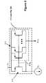
- FIG. 3which shows four exemplary electrodes E 1 , E 2 , E 3 , and E 4 , each having their own dedicated and hard-wired current source 500 and sink 501 circuitry.
- a primary clinical benefit of having the ability control current on each electrodeis that it allows precise shaping of the electric field used for stimulation from the array of electrodes. Systems without this ability have less control of the field and are subject to variations and changes in impedance among electrodes.
- the current source 500 and sink 501 circuitry hard-wired at each electrodeare sometimes respectively referred to as PDACs and NDACs, reflecting the fact that the sources 500 are typically formed of P-type transistors while the sinks 501 are typically formed of N-type transistors.
- the use of transistors of these polaritiesis sensible given that the source is biased to a high voltage (V+), where P-type transistors are most logical, while the sink is biased to a low voltage (V ⁇ ), where N-type transistors are most logical, as shown in FIG. 2 .
- the substrate connection (not shown) for the transistorswould typically be tied to the appropriate power supply, either V+ or V ⁇ , but could also be tied to the transistors' sources.
- the current sources (PDACs) and sinks (NDACs) active at any given timecan be programmed.
- the source circuitry at electrode E 2 on the IPGis currently active, while the sink circuitry at electrode E 3 is also currently active.
- electrodes E 2 and E 3could be switched such that E 2 now operates as the sink, while E 3 operates as the source, or new sources or sinks could be chosen, etc., depending on how the logic in the IPG is programmed in accordance with optimal therapy for the patient in which the IPG is implanted.
- each electrodehas its own dedicated source (i.e., PDAC) and sink (i.e., NDAC) circuitry.
- PDACdedicated current source circuitry
- NDACsink
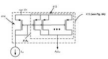
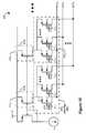
- FIG. 4Further details of such dedicated current source circuitry 500 for a particular electrode (e.g., E x ) as disclosed in the '969 patent is shown in FIG. 4 .
- Dedicated current sink circuitry 501 for each electrodesimilar to the current source circuitry 500 but differing in polarity (see e.g., FIG. 2 ), would likewise be hardwired to the electrode E X , but is not shown for convenience in FIG. 4 . (However, both the source and sink circuitry are shown in a simplified manner in FIG. 7 ).
- a coupling capacitortypically hardwired at each electrode Ex (see '969 patent, FIG. 3 , element 203 ).
- the source circuitry of FIG. 4can be programmed to output a source current of a particular magnitude.
- the circuitry as shownis capable of outputting to the electrode Ex a current I out ranging from I ref to 127 I ref in increments of I ref , depending on the status of the control bits (Bit ⁇ 1 :M>). This occurs as follows: each control bit, when selected, contributes 2 (M ⁇ 1) worth of current to the output current, I out , through activation of pass transistors 530 in each of the M stages that comprise the current source.
- control bits Bit ⁇ 1 , 3 , 5 , 6 >would be enabled (active low) to turn on transistors 530 1 , 530 3 , 530 5 , and 530 6 , which respectively contribute I ref, 4I ref, 16I ref and 32I ref , in sum, 53I ref .
- each stageis shown as having its own current source I ref , it would usually be the case that each stage taps into a singular reference current (not shown for convenience), which is preferred to ensure current uniformity across the stages.
- this current source/sink architecture of FIGS. 3 and 4does not comprise an efficient use of space on the integrated circuit in the IPG on which the current source/sink circuitry is fabricated.
- the IPGmight contain 16 electrodes, E 1 through E 16 .
- PDACsource
- NDACNDAC
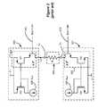
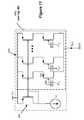
- FIG. 5Another current source/sink architecture is disclosed in the above-incorporated '227 patent, and in particular in FIG. 4A of the '227 patent, salient aspects of which are summarized in the present application in FIGS. 5 and 6 .
- the architecture of the '227 patentalso uses a plurality of current sources and sinks, and further uses a low impedance switching matrix that intervenes between the sources/sinks and the electrodes E x . Notice that each source/sink pair is hard-wired together at nodes 333 , such that the switching matrix intervenes between the common nodes 333 and the electrodes.
- any of the nodes 333may be connected to any of the electrodes E X at any time.
- FIGS. 5 and 6suffer from drawbacks.
- this architectureputs additional resistance—namely the resistance of the switches in the switching matrix—in the output path between the power supply in the DAC circuitry and the electrode.
- additional resistancenamely the resistance of the switches in the switching matrix
- FIG. 6which shows the architecture of FIG. 5 in further detail, it is desired that the resistance be minimized in the output path between the power supply V+ or V ⁇ and a given electrode E X . This is because any resistance in the output path will give rise to a voltage drop in the output path (the output path resistance times I out ) which is not otherwise useful in the context of the circuitry.
- FIGS. 5 and 6are further inefficient from a layout perspective. Due to the common node 333 between a given PDAC source and NDAC sink pair, only one DAC in each pair can be active at any time. Thus, and like the architecture of FIGS. 3 and 4 , DAC circuitry is guaranteed to go unused at any particular time. More specifically, at least 50% of the DAC circuitry (the unselected DAC in a pair), and likely more, will go unused at any given time, which again is a wasteful use of layout on the integrated circuit.
- the implantable stimulator artor more specifically the IPG or SCS system art, would be benefited by an architecture that allows variable currents to be provided at a number of electrodes, but in a more space-efficient manner.
- the source/sink circuitry 500 / 501can include a stage or stages 550 which provide a fraction of the reference current, I ref . These stages 550 , are controlled by another control bit, Bit ⁇ 0 >(designated as “0+” for the source and “0 ⁇ ” for the sink).
- fractional values of (1 ⁇ 2) mi.e., 1 ⁇ 2*I ref , 1 ⁇ 4*I ref , 1 ⁇ 8*I ref , etc.
- 1/me.g., 1 ⁇ 2*I ref , 1 ⁇ 3*I ref , etc.
- a current generation architecturefor an implantable stimulator device such as an Implantable Pulse Generator (IPG) or more specifically for a Spinal Cord Stimulation (SCS) system.
- IPGImplantable Pulse Generator
- SCSSpinal Cord Stimulation
- current source and sink circuitryare both divided into coarse and fine portions, which respectively have the ability to provide a coarse and a fine amount of current to a specified electrode on the IPG.
- the coarse portion of the current generation circuitryis distributed across all of the electrodes and so can source or sink current to any of the electrodes.
- the coarse portionis divided into a plurality of stages, each of which is capable via an associated switch bank of sourcing or sinking an amount of current to or from any one of the electrodes on the device.
- Each stageis preferably formed of a current mirror for receiving a reference current and outputting a current to that stage's switch bank.
- the output current in the stagepreferably represents a scaled version of the reference current, i.e., the output current comprises the reference current times a scalar at the stage, which can be set by wiring a desired number of output transistors in the current mirror in parallel.
- the scalars of the different stagesare uniformly set to provide a coarse increment of the reference current to the switch banks, and hence to any of the electrodes.
- the fine portion of the current generation circuitryincludes source and sink circuitry dedicated to each of the electrode on the device.
- the dedicated circuitrypreferably comprises digital-to-analog current converters (DACs).
- DACsinclude a current mirror and also receive the above-noted reference current.
- the reference currentis amplified in the DACs in fine increments by appropriate selection of fine current control signals.
- FIG. 1shows an exemplary implantable pulse generator (IPG) and its associated electrode array in accordance with the prior art.
- IPGimplantable pulse generator
- FIG. 2shows an exemplary prior art current source and a corresponding current sink for an IPG, each having current digital-to-analog converter (DAC) circuitry in series with a load.
- DACdigital-to-analog converter
- FIG. 3shows a prior art architecture for coupling current sources and sinks to a plurality of electrodes using hard-wired dedicated circuitry at each electrode.
- FIG. 4shows the layout complexity of one of the current sources of FIG. 3 .
- FIG. 5shows a prior art architecture for coupling current source and sinks to a plurality of electrodes using a switching matrix.
- FIG. 6shows drawbacks relating to the architecture of FIG. 5 relating to unnecessary power consumption within the IPG.
- FIG. 7shows a prior art modification to the architecture of FIGS. 3 and 4 in which a fractional amount of a reference current can be provided at an electrode.
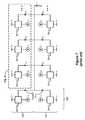
- FIGS. 8A and 8Billustrates an improved current source/sink architecture having both coarse and fine current control in accordance with one embodiment of the invention.
- FIG. 9shows the current mirror circuitry useable in the coarse circuitry portion of the architecture of FIGS. 8A and 8B .
- FIG. 10shows the switch banks used in the coarse circuitry portion to distribute a coarse amount of current from any of the current mirrors to any of the electrodes.
- FIG. 11shows the PDAC used in the fine circuitry portion of the architecture of FIGS. 8A and 8B which is dedicated at each electrode.
- FIGS. 12A and 12Billustrate an alternative embodiment to that shown in FIG. 8A and 8B in which two different reference currents are used for the coarse and fine portions.
- FIG. 13illustrates the control signals necessary to operate the disclosed embodiment of the current generation circuitry shown in FIGS. 8A and 8B .
- the present inventionmay be used with an implantable pulse generator (IPG), or similar electrical stimulator and/or electrical sensor, that may be used as a component of numerous different types of stimulation systems.
- IPGimplantable pulse generator
- SCSspinal cord stimulation
- the inventionis not so limited. Rather, the invention may be used with any type of implantable electrical circuitry that could benefit from efficient current source/sink circuitry.
- the present inventionmay be used as part of a pacemaker, a defibrillator, a cochlear stimulator, a retinal stimulator, a stimulator configured to produce coordinated limb movement, a cortical and deep brain stimulator, or in any other neural stimulator configured to treat urinary incontinence, sleep apnea, shoulder sublaxation, etc.
- exemplary embodiments of the present inventioninvolve the architecture used in the current source and sink circuitry, which are sometimes respectively referred to as the PDAC and NDAC circuitry.
- PDAC and NDAC circuitryare sometimes respectively referred to as the PDAC and NDAC circuitry.
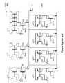
- FIGS. 8-13A new and improved current generation architecture is illustrated in FIGS. 8-13 .
- the new architecturelike previous architectures, employs current source and current sink circuitry, respectively labeled in FIGS. 8A and 8B as circuitry 400 and 401 , which would logically be implemented for example on analog IC.
- the source circuitry 400is in solid lines while the sink circuitry 401 is illustrated in mere dotted lines.
- the sink circuitry 401while not specifically discussed, is similar in design and function to the source circuitry 400 , although differing in polarity (e.g., connection to negative power supply V ⁇ , use of N-channel transistors, etc.).
- the source circuitry 400is specifically discussed in this disclosure, although it should be understood that the sink circuitry 401 is similar in all material respects and of equal importance.
- each of the source/sink circuitry 400 / 401is divided into two parts: a coarse portion 402 ( FIG. 8A ) and a fine portion 403 ( FIG. 8B ).
- the coarse portion 402allows a coarse amount of current to be provided to a particular electrode.
- the amount of current which can be programmed to be source or sunk at a particular electrode by the coarse portion 402is incrementable in relatively-large increments.
- the amount of current which can be programmed to be sourced or sunk at a particular electrode by the fine portion 403is incrementable in relatively-small increments. Having both coarse and fine portions 402 and 403 allows for efficient and dynamic control of the current at a particular electrode, as will be explained further below.
- the coarse current circuitry 402preferably does not involve dedicating or hard-wiring source and sink circuitry to each electrode E 1 through EN on the IPG 100 . Instead, the coarse portion 402 of the source and sink circuitry 400 , 401 is shared or distributed amongst the various electrodes via a network of switch banks 405 , as will be explained below.
- the source circuitry 400comprises various current mirrors 410 and various switch banks 405 .
- Each switch bankcomprises N switches, which corresponds to the number of electrodes on the IPG 100 .
- N*L switches 417 in the switch banks 405controlled by N*L control signals (C N,L ).
- the control signals to the switches 417may need to be level shifted to DC values appropriate for the switches 417 , which can easily occur via level shifters 415 , as one skilled in the art will understand.
- the switches 417are preferably single transistors of a logical polarity depending on whether they are present in the source circuitry 400 (P-channels) or the sink circuitry 401 (N-channels). However, other structures could also be used for the switches 417 , such as pass gates or transmission gates, etc.
- the current mirrors 410 in the coarse portion 402receive a reference current, I ref . Because it may be useful to set this reference current to a particular value, a PDAC 407 can be used to convert an initial reference current I 1 to the true reference current I ref sent to each of the current mirrors 410 .
- the PDAC 407can comprise any structure known in the art for programming the amplification of a current on the basis of digital inputs.
- the PDACcan be constructed as in FIG. 4 . As shown, the PDAC 407 scales the initial reference current I 1 by a factor of Z to produce the true reference current I ref . In this way, the currents ultimately sent to the electrodes can be further (and globally) varied by adjusting the gain of the PDAC 407 .
- PDAC 407is digitally controllable, it can be controlled to different values at different points in time. This being said however, PDAC 407 is not required in all embodiments of the invention, and the reference current I ref can be provided in different ways.
- the various current mirrors 410take the reference current I ref and scale that current to produce currents of desired magnitudes in each of the L stages of the coarse portion 402 .
- the first stagescales I ref by A 1 , the second by A 2 , and so on.
- the various scalars A 1 , A 2 , . . . A Lcan be different or can be the same in each of the stages.
- each of the scalars A 1 to A Lare set to the same value of 5 and thus each of the L stages outputs the same amount of current (5I ref ) to their respective switch banks 405 .
- five transistors 413are placed in parallel with the balancing transistor 414 in the output stages of the current mirrors 410 , as is shown in FIG. 9 .
- current mirrors 410are simply one example of a current converter, i.e., a circuit used to convert one current (I ref ) to another current (A x I ref ).
- Many other circuits capable of performing this functionare known in the art, as thus the use of current mirrors in each stage should be understood as merely exemplary.
- the current mirrors 410 in the coarse current circuitry 402are not individually selectable in and of themselves, i.e., they do not have bit select transistors as in the DACs of FIGS. 3 and 4 . They are always on and supplying current to the switch banks 405 , with selection or not of a particular current mirror 410 's current occurring in its given switch bank 405 .
- each of the L switch banks 405contains N switches, S N , each of which is capable of routing the output current from its current mirror 410 x (A x I ref ) to any of the electrodes E x on the IPG 100 , depending on the status of the coarse current control signals C N,L .
- control signal C y,xcan send that stage's current to E y .
- each stageis controllable to send its output current to more than one of the electrodes and thus can affect the current at any given electrode, and multiple stages can work together to produce a current at a given electrode.
- stage Lwould necessarily require N switches.
- a given stagemight comprise less than N switches, foregoing the ability to send that stage's current to a particular electrode E X .
- FIG. 8Aillustrates a preferred embodiment, other designs are possible that still achieve the benefits of the architecture disclosed herein.
- the minimum current resolution provided by any one of the L current mirrors 410is 5I ref , which can be considered as a coarse current resolution of the coarse portion 402 of the current source circuitry 400 . Accordingly, to additionally provide the ability to make fine adjustments to the current provided at the electrodes, fine current source and sink circuitry 403 is also provided.
- fine portion 403is preferably hard-wired to each of the N electrodes.
- the fine portion 403is similar to architecture of FIGS. 3 and 4 , which likewise used dedicated source and sink circuitry at each electrode.
- the use of dedicated source and sink circuitry at each electrodecan be inefficient (guaranteed unused circuitry, etc.).
- any inefficiency in this regardis offset by the concurrent use of the coarse circuitry 402 to set the current at any given electrode, as will be explained below.
- the fine portion 403 of the source circuitry 400comprises a PDAC 409 at each electrode.
- each electrodewill also preferably have a corresponding NDAC for sinking current, as shown in dotted lines in FIG. 8B , but not discussed for simplicity).
- PDACs 409may be similar in design and architecture to the PDAC 407 used to set the reference current, I ref (see FIG. 8A ), but again any current generation circuitry can be used.
- each PDAC 409receives the reference current from PDAC 407 , I ref (see FIG. 8A ), as well as fine current control signals (F J,N ) used to set the amount of current output by each PDAC 409 .
- each PDAC 409preferably constitutes a current mirror having a balancing transistor 424 and a plurality (J) of output transistors 422 (stages), each gated by one of J control signals (F 1,X to F J,X ).
- Each of the output transistors 422are connected in parallel, and are allowed to contribute I ref (i.e., the input current) to the output current, depending on which of the selection transistors 431 are selected by fine current control signals F J,N .
- each stage (PDAC) 409can output a maximum current of 4I ref , which of course requires that all fine current control signals (i.e., F 1,X thought F J,X ) for a given stage (electrode) be activated.
- level shifters 430can be used to convert the fine control signals to appropriate levels to control the switches 431 .
- a minimum of 0I ref and a maximum of 4I ref , in increments of I refcan be sourced by the fine portion 403 of the current source circuitry 400 for any given electrode E X .
- the sink circuitry 401would be similar.
- the fine portion 403have a current resolution, I ref , which is smaller than the current resolution of the coarse portion 402 , 5I ref . Because of this different in resolution, both portions can be used simultaneously to set a particular current at a given electrode. For example, and returning to the example illustrated in the Background, assume that it is desired to source a current of 53I ref at electrode E 2 .
- any ten of the current sources 410can be activated via the coarse control signals corresponding to electrode E 2 (C X,2 ) to provide 50I ref to electrode E 2 .
- any of three fine current control signals corresponding to electrode E 2 (F X,2 )can be activated to provide an additional 3I ref worth of current in addition to the 50I ref provided by the coarse portion, resulting in the desired total current of 53I ref .
- the electrode-dedicated PDACs 409can provide a fine current resolution using other designs, and the particular design of the PDACs is not critical to embodiments of the invention.
- the number of stages L used in the coarse portion 402is preferably equal to (100/(J+1)) ⁇ 1.
- Jthe number of stages L will be equal to 19, thereby allowing the coarse portion 402 to supply approximately 95% of the current range to any electrode E X with a resolution of approximately 5%.
- the fine portion 403supplies approximately the remaining 5% of the current to any electrode E X at the higher resolution of approximately 1%.
- these valuesare merely exemplary.
- each PDAC 409 in the fine portion 403outputs a current with a fine resolution, I ref2
- I ref15I ref2
- control signals necessary to operate and control the disclosed current source/sink circuitryare shown in FIG. 13 . Shown are the coarse (C N,L ) and fine (F J,N ) control signals for both the source circuitry (PDACs; designated with a “+”) and the sink circuitry (NDACs; designated with a “ ⁇ ”). These control signals are ultimately generated by a microcontroller 570 , which can be the microcontroller otherwise used to implement the logic functions in the IPG.
- the current source/sink circuitrycan be implemented on an analog integrated circuit, which receives the control signals from a digital integrated circuit. Again, the specific details concerning the integration of the current source/sink circuitry with the logic can occur in any number of ways, as one skilled in the art will readily recognize.
- circuitryis kept to a minimum through reduction of the use of dedicated circuitry which otherwise might be guaranteed to go unused at particular points in time. In large part, this benefit is the result of the distributed nature of the coarse portion 402 of the circuitry across all of the electrodes. While the disclosed design does rely on the use of some dedicated circuitry—specifically, the fine portion 403 —such circuitry is preferably kept to a minimum. In any event, such additional dedicated circuitry amounts to a good trade off when it is recognized that this reduces the number of necessary control signals.
- the new architectures of FIGS. 8-12comprise one less component in the output path, which reduces unwanted voltage drops in the output path and results in power savings.
- FIGS. 9 and 10which shows the circuitry in the coarse portion 402 , only two components intervene between the power supply V+ and a given electrode: the current mirror output transistor(s) 413 and the selection switches 417 from the switch banks 405 .
- the fine portion 403shown in FIG. 11 , again only two components intervene between the power supply V+ and a given electrode: the current mirror output transistors 422 and the selection switches 431 .
- the selection switches 417linearize the current sources 410 by reducing the Vds voltage drop across the current mirrors on electrodes that require less compliance voltage than the difference of V+ to V ⁇ . If it were not for the switches 417 , the entire excess compliance drop would be across the current mirror 410 and the current would tend to be a little higher than programmed on electrodes requiring less compliance voltage.
- reference to an electrode implantable adjacent to tissue to be stimulatedincludes electrodes on the implantable stimulator device, or associated electrode leads, or any other structure for stimulating tissue.
- an electrode implantable adjacent to tissue to be stimulatedis to be understood without regard to any output capacitance, such as coupling capacitances C N included in the header connector 192 or elsewhere (see FIG. 7 ).
- any output capacitancesuch as coupling capacitances C N included in the header connector 192 or elsewhere (see FIG. 7 ).
- nodes on both sides of such a coupling capacitor or other output impedanceare, in the context of this invention, not materially different from an architectural standpoint, such that either node would be considered as the electrode node implantable adjacent to tissue to be stimulated.
- other impedancese.g., if an output resistor was used in addition to or in lieu of a coupling capacitor.
Landscapes
- Health & Medical Sciences (AREA)
- Animal Behavior & Ethology (AREA)
- Public Health (AREA)
- Engineering & Computer Science (AREA)
- Biomedical Technology (AREA)
- Nuclear Medicine, Radiotherapy & Molecular Imaging (AREA)
- Radiology & Medical Imaging (AREA)
- Life Sciences & Earth Sciences (AREA)
- Neurology (AREA)
- Neurosurgery (AREA)
- Veterinary Medicine (AREA)
- General Health & Medical Sciences (AREA)
- Pain & Pain Management (AREA)
- Orthopedic Medicine & Surgery (AREA)
- Cardiology (AREA)
- Heart & Thoracic Surgery (AREA)
- Electrotherapy Devices (AREA)
- Prostheses (AREA)
Abstract
Description
Claims (36)
Priority Applications (15)
| Application Number | Priority Date | Filing Date | Title |
|---|---|---|---|
| US11/550,763US8620436B2 (en) | 2005-07-08 | 2006-10-18 | Current generation architecture for an implantable stimulator device having coarse and fine current control |
| DE602007006539TDE602007006539D1 (en) | 2006-10-18 | 2007-06-27 | POWER GENERATION ARCHITECTURE FOR AN IMPLANTABLE STIMULATOR WITH GROUND AND FINE-CURRENT CONTROL |
| CA2665422ACA2665422C (en) | 2006-10-18 | 2007-06-27 | Current generation architecture for an implantable stimulator device having coarse and fine current control |
| ES07799080TES2345293T3 (en) | 2006-10-18 | 2007-06-27 | CURRENT GENERATION ARCHITECTURE FOR AN IMPLANTABLE STIMULATOR DEVICE THAT HAS THICK AND FINE CURRENT CONTROL. |
| AU2007313117AAU2007313117B2 (en) | 2006-10-18 | 2007-06-27 | Current generation architecture for an implantable stimulator device having coarse and fine current control |
| PCT/US2007/072238WO2008048725A1 (en) | 2006-10-18 | 2007-06-27 | Current generation architecture for an implantable stimulator device having coarse and fine current control |
| EP07799080AEP2081640B1 (en) | 2006-10-18 | 2007-06-27 | Current generation architecture for an implantable stimulator device having coarse and fine current control |
| AT07799080TATE467438T1 (en) | 2006-10-18 | 2007-06-27 | POWER GENERATION ARCHITECTURE FOR AN IMPLANTABLE STIMULATOR WITH COARSE AND FINE POWER CONTROL |
| US12/838,260US8706238B2 (en) | 2005-07-08 | 2010-07-16 | Current generation architecture for an implantable stimulator device having coarse and fine current control |
| AU2010212255AAU2010212255B2 (en) | 2006-10-18 | 2010-08-10 | Current generation architecture for an implantable stimulator device |
| US14/141,413US9308371B2 (en) | 2005-07-08 | 2013-12-26 | Current generation architecture for an implantable stimulator device having coarse and fine current control |
| US14/203,120US9037249B2 (en) | 2005-07-08 | 2014-03-10 | Current generation architecture for an implantable stimulator device having coarse and fine current control |
| US15/091,969US9956411B2 (en) | 2005-07-08 | 2016-04-06 | Current generation architecture for an implantable stimulator device having coarse and fine current control |
| US15/903,775US10744325B2 (en) | 2005-07-08 | 2018-02-23 | Current generation architecture for an implantable stimulator device having coarse and fine current control |
| US16/904,146US11452873B2 (en) | 2005-07-08 | 2020-06-17 | Current generation architecture for an implantable stimulator device having coarse and fine current control |
Applications Claiming Priority (2)
| Application Number | Priority Date | Filing Date | Title |
|---|---|---|---|
| US11/177,503US8606362B2 (en) | 2005-07-08 | 2005-07-08 | Current output architecture for an implantable stimulator device |
| US11/550,763US8620436B2 (en) | 2005-07-08 | 2006-10-18 | Current generation architecture for an implantable stimulator device having coarse and fine current control |
Related Parent Applications (1)
| Application Number | Title | Priority Date | Filing Date |
|---|---|---|---|
| US11/177,503Continuation-In-PartUS8606362B2 (en) | 2005-07-08 | 2005-07-08 | Current output architecture for an implantable stimulator device |
Related Child Applications (2)
| Application Number | Title | Priority Date | Filing Date |
|---|---|---|---|
| US12/838,260ContinuationUS8706238B2 (en) | 2005-07-08 | 2010-07-16 | Current generation architecture for an implantable stimulator device having coarse and fine current control |
| US14/141,413ContinuationUS9308371B2 (en) | 2005-07-08 | 2013-12-26 | Current generation architecture for an implantable stimulator device having coarse and fine current control |
Publications (2)
| Publication Number | Publication Date |
|---|---|
| US20070100399A1 US20070100399A1 (en) | 2007-05-03 |
| US8620436B2true US8620436B2 (en) | 2013-12-31 |
Family
ID=38659618
Family Applications (7)
| Application Number | Title | Priority Date | Filing Date |
|---|---|---|---|
| US11/550,763Active2030-07-02US8620436B2 (en) | 2005-07-08 | 2006-10-18 | Current generation architecture for an implantable stimulator device having coarse and fine current control |
| US12/838,260Expired - Fee RelatedUS8706238B2 (en) | 2005-07-08 | 2010-07-16 | Current generation architecture for an implantable stimulator device having coarse and fine current control |
| US14/141,413Expired - LifetimeUS9308371B2 (en) | 2005-07-08 | 2013-12-26 | Current generation architecture for an implantable stimulator device having coarse and fine current control |
| US14/203,120Expired - LifetimeUS9037249B2 (en) | 2005-07-08 | 2014-03-10 | Current generation architecture for an implantable stimulator device having coarse and fine current control |
| US15/091,969Expired - LifetimeUS9956411B2 (en) | 2005-07-08 | 2016-04-06 | Current generation architecture for an implantable stimulator device having coarse and fine current control |
| US15/903,775Active2025-12-19US10744325B2 (en) | 2005-07-08 | 2018-02-23 | Current generation architecture for an implantable stimulator device having coarse and fine current control |
| US16/904,146Active2026-05-05US11452873B2 (en) | 2005-07-08 | 2020-06-17 | Current generation architecture for an implantable stimulator device having coarse and fine current control |
Family Applications After (6)
| Application Number | Title | Priority Date | Filing Date |
|---|---|---|---|
| US12/838,260Expired - Fee RelatedUS8706238B2 (en) | 2005-07-08 | 2010-07-16 | Current generation architecture for an implantable stimulator device having coarse and fine current control |
| US14/141,413Expired - LifetimeUS9308371B2 (en) | 2005-07-08 | 2013-12-26 | Current generation architecture for an implantable stimulator device having coarse and fine current control |
| US14/203,120Expired - LifetimeUS9037249B2 (en) | 2005-07-08 | 2014-03-10 | Current generation architecture for an implantable stimulator device having coarse and fine current control |
| US15/091,969Expired - LifetimeUS9956411B2 (en) | 2005-07-08 | 2016-04-06 | Current generation architecture for an implantable stimulator device having coarse and fine current control |
| US15/903,775Active2025-12-19US10744325B2 (en) | 2005-07-08 | 2018-02-23 | Current generation architecture for an implantable stimulator device having coarse and fine current control |
| US16/904,146Active2026-05-05US11452873B2 (en) | 2005-07-08 | 2020-06-17 | Current generation architecture for an implantable stimulator device having coarse and fine current control |
Country Status (8)
| Country | Link |
|---|---|
| US (7) | US8620436B2 (en) |
| EP (1) | EP2081640B1 (en) |
| AT (1) | ATE467438T1 (en) |
| AU (2) | AU2007313117B2 (en) |
| CA (1) | CA2665422C (en) |
| DE (1) | DE602007006539D1 (en) |
| ES (1) | ES2345293T3 (en) |
| WO (1) | WO2008048725A1 (en) |
Cited By (128)
| Publication number | Priority date | Publication date | Assignee | Title |
|---|---|---|---|---|
| US20150280723A1 (en)* | 2014-03-25 | 2015-10-01 | Mediatek Inc. | Oscillating signal generator, phase-lock loop circuit using the oscillating signal generator and control method of the oscillating signal generator |
| US9166441B2 (en) | 2013-07-29 | 2015-10-20 | Alfred E. Mann Foundation For Scientific Research | Microprocessor controlled class E driver |
| US9446241B2 (en) | 2013-03-15 | 2016-09-20 | Alfred E. Mann Foundation For Scientific Research | Current sensing multiple output current stimulators |
| WO2018048912A1 (en) | 2016-09-10 | 2018-03-15 | Boston Scientific Neuromodulation Corporation | Use models for a current generation architecture for an implantable medical device |
| WO2018048923A1 (en) | 2016-09-10 | 2018-03-15 | Boston Scientific Neuromodulation Corporation | Pulse definition circuitry for creating stimulation waveforms in an implantable pulse generator |
| WO2018048909A1 (en) | 2016-09-10 | 2018-03-15 | Boston Scientific Neuromodulation Corporation | Current generation architecture for an implantable medical device |
| WO2018048914A1 (en) | 2016-09-10 | 2018-03-15 | Boston Scientific Neuromodulationcorporation | Biasing of a current generation architecture for an implantable medical device |
| WO2018048922A1 (en) | 2016-09-10 | 2018-03-15 | Boston Scientific Neuromodulation Corporation | Pulse definition circuitry for creating stimulation waveforms in an implantable pulse generator |
| WO2018048916A1 (en) | 2016-09-10 | 2018-03-15 | Boston Scientific Neuromodulationcorporation | Passive charge recovery circuitry for an implantable medical device |
| WO2018048917A1 (en) | 2016-09-10 | 2018-03-15 | Boston Scientific Neuromodulation Corporation | Compliance voltage monitoring and adjustment in an implantable medical device |
| WO2018048920A1 (en) | 2016-09-10 | 2018-03-15 | Boston Scientific Neuromodulation Corporation | Pulse definition circuitry for creating stimulation waveforms in an implantable pulse generator |
| WO2018048918A1 (en) | 2016-09-10 | 2018-03-15 | Boston Scientific Neuromodulation Corporation | Measurement circuitry for measuring analog values in an implantable pulse generator |
| US9925381B2 (en) | 2015-07-10 | 2018-03-27 | Axonics Modulation Technologies, Inc. | Implantable nerve stimulator having internal electronics without ASIC and methods of use |
| WO2018071114A1 (en) | 2016-10-13 | 2018-04-19 | Boston Scientific Neuromodulation Corporation | Current generation architecture for an implantable medical device including controllable slew rate |
| WO2018097939A1 (en) | 2016-11-23 | 2018-05-31 | Boston Scientific Neuromodulation Corporation | Pulsed passive charge recovery circuitry for an implantable medical device |
| US10149979B2 (en) | 2016-04-04 | 2018-12-11 | Boston Scientific Neuromodulation Corporation | System to estimate the location of a spinal cord physiological midline |
| WO2019032987A1 (en) | 2017-08-11 | 2019-02-14 | Boston Scientific Neuromodulation Corporation | Paresthesia-free spinal cord stimulation system |
| WO2019055812A1 (en) | 2017-09-15 | 2019-03-21 | Boston Scientific Neuromodulation Corporation | Current generation architecture for an implantable stimulator device including distributor circuitry for sending an amplitude-scaled current to digital-to-analog converters at the electrodes |
| WO2019055427A1 (en) | 2017-09-12 | 2019-03-21 | Boston Scientific Neuromodulation Corporation | System and method for determination of connected neurostimulation leads |
| WO2019070406A1 (en) | 2017-10-04 | 2019-04-11 | Boston Scientific Neuromodulation Corporation | Adjustment of stimulation in a stimulator using detected evoked compound action potentials |
| WO2019070376A1 (en) | 2017-10-04 | 2019-04-11 | Boston Scientific Neuromodulation Corporation | System for ensuring a consistent connection of electrodes to a replacement implantable medical device |
| WO2019136072A1 (en) | 2018-01-08 | 2019-07-11 | Boston Scientific Neuromodulation Corporation | Automatic adjustment of sub-perception therapy in an implantable stimulator using detected compound action potentials |
| US10376702B2 (en) | 2016-04-04 | 2019-08-13 | Boston Scientific Neuromodulation Corporation | System to estimate the location of a spinal cord physiological midline |
| US10406368B2 (en) | 2016-04-19 | 2019-09-10 | Boston Scientific Neuromodulation Corporation | Pulse generator system for promoting desynchronized firing of recruited neural populations |
| WO2019177798A1 (en) | 2018-03-12 | 2019-09-19 | Boston Scientific Neuromodulation Corporation | Neural stimulation with decomposition of evoked compound action potentials |
| US10420950B2 (en) | 2015-11-29 | 2019-09-24 | Boston Scientific Neuromodulation Corporation | Implantable pulse generator usable during a trial stimulation phase and externally powered by magnetic inductive coupling |
| WO2019190710A1 (en) | 2018-03-27 | 2019-10-03 | Boston Scientific Neuromodulation Corporation | Hybrid sensing and stimulation utilizing pre-pulsing of waveforms |
| WO2019190678A1 (en) | 2018-03-30 | 2019-10-03 | Boston Scientific Neuromodulation Corporation | Circuitry to assist with neural sensing in an implantable stimulator device |
| WO2019209474A1 (en) | 2018-04-27 | 2019-10-31 | Boston Scientific Neuromodulation Corporation | Anodic stimulation in an implantable stimulator system using asymmetric anodic and cathodic stimulation pulses |
| WO2019217079A1 (en) | 2018-05-09 | 2019-11-14 | Boston Scientific Neuromodulation Corporation | Determination and use of a wellness factor in an implantable medical device system using qualitative and quantitative measurements |
| WO2019236298A1 (en) | 2018-06-04 | 2019-12-12 | Boston Scientific Neuromodulation Corporation | Logging the execution of sub-programs within a stimulation program for an implantable stimulator device |
| WO2020005589A1 (en) | 2018-06-27 | 2020-01-02 | Boston Scientific Neuromodulation Corporation | Stimulation field modelling in an implantable stimulator device |
| WO2020010120A1 (en) | 2018-07-03 | 2020-01-09 | Boston Scientific Neuromodution Corporation | Spinal cord stimulation system modelling relationships between stimulation parameters for automatic customization of sub-perception therapy |
| WO2020041013A1 (en) | 2018-08-23 | 2020-02-27 | Boston Scientific Neuromodulation Corporation | Stimulation using long duration waveform phases in a spinal cord stimulator system |
| US10576292B2 (en) | 2015-11-29 | 2020-03-03 | Boston Scientific Neuromodulation Corporation | Skull-mounted deep brain stimulator |
| US10589090B2 (en) | 2016-09-10 | 2020-03-17 | Boston Scientific Neuromodulation Corporation | Implantable stimulator device with magnetic field sensing circuit |
| US10603500B2 (en) | 2016-01-29 | 2020-03-31 | Axonics Modulation Technologies, Inc. | Methods and systems for frequency adjustment to optimize charging of implantable neurostimulator |
| EP3639887A1 (en) | 2017-09-15 | 2020-04-22 | Boston Scientific Neuromodulation Corporation | Current generation architecture for an implantable stimulator device to promote current steering between electrodes |
| WO2020162990A2 (en) | 2019-02-08 | 2020-08-13 | Boston Scientific Neuromodulationcorporation | Varying stimulation parameters to prevent tissue habituation in a spinal cord stimulation system |
| WO2020163042A1 (en) | 2019-02-08 | 2020-08-13 | Boston Scientific Neuromodulation Corporation | Spinal cord stimulation occurring using monophasic pulses of alternating polarities and passive charge recovery |
| WO2020163037A1 (en) | 2019-02-08 | 2020-08-13 | Boston Scientific Neuromodulation Corporation | Fitting algorithm to determine best stimulation parameter in a spinal cord stimulation system |
| WO2020163044A1 (en) | 2019-02-08 | 2020-08-13 | Boston Scientific Neuromodulation Corporation | Fitting algorithm to determine best stimulation parameter in a spinal cord stimulation system |
| WO2020163041A1 (en) | 2019-02-08 | 2020-08-13 | Boston Scientific Neuromodulation Corporation | Spinal cord stimulation for dorsal column recruitment or suppression using anodic and cathodic pulses |
| WO2020163045A1 (en) | 2019-02-08 | 2020-08-13 | Boston Scientific Neuromodulation Corporation | Tools to assist spinal cord stimulation self-reprogramming |
| WO2020163046A1 (en) | 2019-02-08 | 2020-08-13 | Boston Scientific Neuromodulation Corporation | System for delivering prescribed neuromodulation dose |
| WO2020223165A1 (en) | 2019-04-30 | 2020-11-05 | Boston Scientific Neuromodulation Corporation | Adjustment of stimulation in response to electrode array movement in a spinal cord stimulator system |
| US10842989B2 (en) | 2017-11-08 | 2020-11-24 | Boston Scientific Neuromodulation Corporation | System to improve a spinal cord stimulation model based on a physiological midline location |
| WO2020251900A1 (en) | 2019-06-14 | 2020-12-17 | Boston Scientific Neuromodulation Corporation | Implantable medical device without a wire-wound coil configured to receive wireless power from an external charger |
| WO2020251899A1 (en) | 2019-06-12 | 2020-12-17 | Boston Scientific Neuromodulation Corporation | Posture determination and stimulation adjustment in a spinal cord stimulator system using sensed stimulation artifacts |
| US10881859B2 (en) | 2017-12-13 | 2021-01-05 | Boston Scientific Neuromodulation Corporation | Steering of target poles in an electrode array in a pulse generator system |
| WO2021003290A1 (en) | 2019-07-02 | 2021-01-07 | Boston Scientific Neuromodulation Corporation | Spinal cord stimulation system determining optimal sub-perception therapy by using neural dose |
| US10912942B2 (en) | 2017-09-15 | 2021-02-09 | Boston Scientific Neuromoduiation Corporation | Current generation architecture for an implantable stimulator device to promote current steering between electrodes |
| WO2021026151A1 (en) | 2019-08-06 | 2021-02-11 | Boston Scientific Neuromodulation Corporation | Neural sensing in an implantable stimulator device during passive charge recovery |
| US10940316B2 (en) | 2010-06-18 | 2021-03-09 | Cardiac Pacemakers, Inc. | Methods and apparatus for adjusting neurostimulation intensity using evoked responses |
| WO2021046120A1 (en) | 2019-09-06 | 2021-03-11 | Boston Scientific Neuromodulation Corporation | Management of compliance voltage for a stimulator device |
| US10974042B2 (en) | 2018-03-26 | 2021-04-13 | Boston Scientific Neuromodulation Corporation | System and methods for heart rate and electrocardiogram extraction from a spinal cord stimulation system |
| WO2021076234A1 (en) | 2019-10-18 | 2021-04-22 | Boston Scientific Neuromodulation Corporation | Neurostimulation device providing sub-perception stimulation |
| WO2021080727A1 (en) | 2019-10-21 | 2021-04-29 | Boston Scientific Neuromodulation Corporation | Assessment and adjustment of time-varying pulse patterns in a spinal cord stimulator system |
| US10994143B2 (en) | 2018-05-11 | 2021-05-04 | Boston Scientific Neuromodulation Corporation | Stimulation waveforms with high- and low-frequency aspects in an implantable stimulator device |
| US11013912B2 (en) | 2018-04-27 | 2021-05-25 | Boston Scientific Neuromodulation Corporation | Neurostimulation system for delivering selectivity modes |
| WO2021141652A1 (en) | 2020-01-09 | 2021-07-15 | Boston Scientific Neuromodulation Corporation | External controller for controlling sub-perception stimulation |
| US11083887B2 (en) | 2017-09-12 | 2021-08-10 | Boston Scientific Neuromodulation Corporation | Techniques for sensing incorrect lead connection to an implantable stimulator device |
| WO2021167783A1 (en) | 2020-02-21 | 2021-08-26 | Boston Scientific Neuromodulation Corporation | Selective stimulation of peripheral nerves |
| WO2021178207A1 (en) | 2020-03-03 | 2021-09-10 | Boston Scientific Neuromodulation Corporation | Digital-to-analog converter circuitry for a stimulator device having non-linear amplitude adjustment |
| WO2021178105A1 (en) | 2020-03-06 | 2021-09-10 | Boston Scientific Neuromodulation Corporation | Neurostimulation device providing sub-perception stimulation |
| US11173308B2 (en) | 2018-03-05 | 2021-11-16 | Boston Scientific Neuromodulation Corporation | Virtual target pole adjustment based on nerve root trajectory |
| US11241580B2 (en) | 2018-06-01 | 2022-02-08 | Boston Scientific Neuromodulation Corporation | Artifact reduction in a sensed neural response |
| WO2022035608A1 (en) | 2020-08-10 | 2022-02-17 | Boston Scientific Neuromodulation Corporation | Electrical stimulation systems based on stimulation-evoked responses |
| US11259733B2 (en) | 2019-03-29 | 2022-03-01 | Boston Scientific Neuromodulation Corporation | Neural sensing in an implantable stimulator device during the provision of active stimulation |
| US11273309B2 (en) | 2019-02-08 | 2022-03-15 | Boston Scientific Neuromodulation Corporation | Linking and concurrent steering of multiple pole configurations in a spinal cord stimulation system |
| US11338129B2 (en) | 2019-04-17 | 2022-05-24 | Boston Scientific Neuromodulation Corporation | Selective electrical modulation of neural populations |
| US11338127B2 (en) | 2017-08-11 | 2022-05-24 | Boston Scientific Neuromodulation Corporation | Stimulation modes to adapt customized stimulation parameters for use in a spinal cord stimulation system |
| WO2022109514A1 (en) | 2020-11-20 | 2022-05-27 | Boston Scientific Neuromodulation Corporation | Compliance voltage monitoring and adjustment in an implantable medical device using low side sensing |
| WO2022159375A1 (en) | 2021-01-19 | 2022-07-28 | Boston Scientific Neuromodulation Corporation | Electrical stimulation cuff devices and systems with directional electrode configurations |
| US11413457B2 (en) | 2019-01-22 | 2022-08-16 | Boston Scientific Neuromodulation Corporation | Fitting algorithm for recruiting of neural targets in a spinal cord stimulator system |
| WO2022174233A1 (en) | 2021-02-12 | 2022-08-18 | Boston Scientific Neuromodulation Corporation | Neural feedback assisted dbs |
| WO2022174149A1 (en) | 2021-02-15 | 2022-08-18 | Boston Scientific Neuromodulation Corporation | Systems and methods for programming neuromodulation sequences |
| WO2022174210A1 (en) | 2021-02-12 | 2022-08-18 | Boston Scientific Neuromodulation Corporation | Automated selection of electrodes and stimulation parameters in a deep brain stimulation system employing directional leads |
| WO2022183161A1 (en) | 2021-02-24 | 2022-09-01 | Boston Scientific Neuromodulation Corporation | Closed loop control in spinal cord stimulation |
| WO2022198172A1 (en) | 2021-03-18 | 2022-09-22 | Boston Scientific Neuromodulation Corporation | Systems for lead movement detection and response in dbs therapy |
| US20220321139A1 (en)* | 2021-04-06 | 2022-10-06 | Boston Scientific Neuromodulation Corporation | Current Generation Architecture for an Implantable Stimulator Device |
| US11504526B2 (en) | 2019-05-30 | 2022-11-22 | Boston Scientific Neuromodulation Corporation | Methods and systems for discrete measurement of electrical characteristics |
| WO2022245931A1 (en) | 2021-05-21 | 2022-11-24 | Boston Scientific Neuromodulation Corporation | Electrical stimulation cuff devices and systems with helical arrangement of electrodes |
| WO2022251787A1 (en) | 2021-05-26 | 2022-12-01 | Boston Scientific Neuromodulation Corporation | Forecasting stimulation adjustments in a stimulator system using time series analysis |
| WO2022256767A1 (en) | 2021-06-02 | 2022-12-08 | Boston Scientific Neuromodulation Corporation | Precise targeting in a spinal cord stimulation system |
| WO2022265620A1 (en) | 2021-06-14 | 2022-12-22 | Boston Scientific Neuromodulation Corporation | Paresthesia-free spinal cord stimulation occurring at lower frequencies involving perception threshold determinations |
| WO2022266601A1 (en) | 2021-06-17 | 2022-12-22 | Boston Scientific Neuromodulation Corporation | Ramping of neural dosing for comprehensive spinal cord stimulation therapy |
| US11565117B2 (en) | 2019-05-02 | 2023-01-31 | Boston Scientific Neuromodulation Corporation | Amplitude modulating waveform pattern generation for stimulation in an implantable pulse generator |
| WO2023028435A1 (en) | 2021-08-24 | 2023-03-02 | Boston Scientific Neuromodulation Corporation | User interface solutions for providing sub-perception stimulation in an implantable stimulator system |
| US11612751B2 (en) | 2017-08-11 | 2023-03-28 | Boston Scientific Neuromodulation Corporation | Stimulation configuration variation to control evoked temporal patterns |
| US11623095B2 (en) | 2019-06-20 | 2023-04-11 | Boston Scientific Neuromodulation Corporation | Methods and systems for interleaving waveforms for electrical stimulation and measurement |
| US11633138B2 (en) | 2019-03-29 | 2023-04-25 | Boston Scientific Neuromodulation Corporation | Circuitry to assist with neural sensing in an implantable stimulator device in the presence of stimulation artifacts |
| US11642537B2 (en) | 2019-03-11 | 2023-05-09 | Axonics, Inc. | Charging device with off-center coil |
| WO2023081180A1 (en) | 2021-11-05 | 2023-05-11 | Boston Scientific Neuromodulation Corporation | Closed loop stimulation based on response avoidance |
| US11738198B2 (en) | 2019-05-10 | 2023-08-29 | The Freestate Of Bavaria Represented By The Julius Maximilians-Universität Würzbrg | System to optimize anodic stimulation modes |
| US11745021B2 (en) | 2020-03-26 | 2023-09-05 | Boston Scientific Neuromodulation Corporation | Graphical user interface for adjusting current magnitude in a stimulator device |
| WO2023183838A1 (en) | 2022-03-25 | 2023-09-28 | Boston Scientific Neuromodulation Corporation | Implantable pulse generator charging alerts |
| US11794016B2 (en) | 2020-02-14 | 2023-10-24 | Boston Scientific Neuromodulation Corporation | Closed loop control in spinal cord stimulation therapy with non- detectable neural responses |
| US11844947B2 (en) | 2017-08-11 | 2023-12-19 | Boston Scientific Neuromodulation Corporation | Spinal cord stimulation occurring using monophasic pulses of alternating polarities and passive charge recovery |
| US11848090B2 (en) | 2019-05-24 | 2023-12-19 | Axonics, Inc. | Trainer for a neurostimulator programmer and associated methods of use with a neurostimulation system |
| WO2024015240A1 (en) | 2022-07-13 | 2024-01-18 | Boston Scientific Neuromodulation Corporation | Automating bolus stimulation therapy from learned usage |
| US11890480B2 (en) | 2018-07-03 | 2024-02-06 | Boston Scientific Neuromodulation Corporation | Therapy implemented using different sub-perception neuromodulation types |
| WO2024039538A1 (en) | 2022-08-16 | 2024-02-22 | Boston Scientific Neuromodulation Corporation | Adaptive neuromodulation therapy |
| US11931592B2 (en) | 2020-02-13 | 2024-03-19 | Cardiac Pacemakers, Inc. | Output circuitry for multiple-therapy implantable devices |
| US11951314B2 (en) | 2017-08-11 | 2024-04-09 | Boston Scientific Neuromodulation Corporation | Fitting algorithm to determine best stimulation parameter from a patient model in a spinal cord stimulation system |
| US11964152B2 (en) | 2019-05-06 | 2024-04-23 | Advanced Neuromodulation Systems, Inc. | Neurostimulation using one or more cycling parameters for a non-paresthesia stimulation pattern |
| US11975196B2 (en) | 2017-08-11 | 2024-05-07 | Boston Scientific Neuromodulation Corporation | Tools to assist spinal cord stimulation self-reprogramming |
| US11998743B2 (en) | 2020-02-14 | 2024-06-04 | Boston Scientific Neuromodulation Corporation | Systems and methods for using electrospinogram signals for closed loop control in Spinal Cord Stimulation therapy |
| US12023505B2 (en) | 2020-02-05 | 2024-07-02 | Boston Scientific Neuromodulation Corporation | Selection of sensing electrodes in a spinal cord stimulator system using sensed stimulation artifacts |
| US12042656B2 (en) | 2017-08-11 | 2024-07-23 | Boston Scientific Neuromodulation Corporation | Bolus stimulation in a neurostimulation device particularly useful in providing sub-perception stimulation |
| US12053632B2 (en) | 2019-07-26 | 2024-08-06 | Boston Scientific Neuromodulation Corporation | Methods and systems for making electrical stimulation adjustments based on patient-specific factors |
| WO2024167716A1 (en) | 2023-02-07 | 2024-08-15 | Boston Scientific Neuromodulation Corporation | Automated selection of electrodes and stimulation parameters in a deep brain stimulation system using anatomical structures |
| US12090324B2 (en) | 2017-08-11 | 2024-09-17 | Boston Scientific Neuromodulation Corporation | Spinal cord stimulation for dorsal column recruitment or suppression using anodic and cathodic pulses |
| US12130753B2 (en) | 2019-07-26 | 2024-10-29 | Boston Scientific Neuromodulation Corporation | Methods and systems for storage, retrieval, and visualization of signals and signal features |
| WO2024238151A1 (en) | 2023-05-15 | 2024-11-21 | Boston Scientific Neuromodulation Corporation | Computer-assisted programming of neuromodulation therapy |
| WO2024242860A1 (en) | 2023-05-19 | 2024-11-28 | Boston Scientific Neuromodulation Corporation | Patient and context specific neuromodulation therapy |
| WO2024242843A1 (en) | 2023-05-19 | 2024-11-28 | Boston Scientific Neuromodulation Corporation | Customizable signal processing for neuromodulation therapy |
| WO2025038713A1 (en) | 2023-08-15 | 2025-02-20 | Boston Scientific Neuromodulation Corporation | Systems and methods for targeting and dosing spinal cord stimulation |
| WO2025096577A1 (en) | 2023-10-31 | 2025-05-08 | Boston Scientific Neuromodulation Corporation | Use of n-let pulses in a deep brain stimulation system to selectively treat symptoms |
| US12339689B2 (en) | 2021-10-06 | 2025-06-24 | Boston Scientific Neuromodulation Corporation | Voltage regulator for providing a stable output voltage in an implantable stimulator device |
| US12337179B2 (en) | 2021-10-19 | 2025-06-24 | Boston Scientific Neuromodulation Corporation | Stimulation targeting and calibration for enhanced surround inhibition recruitment in spinal cord stimulation therapy |
| US12377273B2 (en) | 2021-12-02 | 2025-08-05 | Boston Scientific Neuromodulation Corporation | Circuitry to assist with neural sensing in an implantable stimulator device in the presence of stimulation artifacts |
| US12377274B2 (en) | 2021-07-22 | 2025-08-05 | Boston Scientific Neuromodulation Corporation | Interpolation methods for neural responses |
| WO2025170861A1 (en) | 2024-02-06 | 2025-08-14 | Boston Scientific Neuromodulation Corporation | Deep brain stimulation neuromodulation targeting |
| WO2025170865A1 (en) | 2024-02-09 | 2025-08-14 | Boston Scientific Neuromodulation Corporation | Paresthesia-free spinal cord stimulation occurring at lower frequencies involving perception threshold determinations |
| US12427324B2 (en) | 2017-08-11 | 2025-09-30 | Boston Scientific Neuromodulation Corporation | Prescribed neuromodulation dose delivery |
| US12427318B2 (en) | 2019-07-02 | 2025-09-30 | Boston Scientific Neuromodulation Corporation | Spinal cord stimulation system determining optimal sub-perception therapy by using neural dose |
| US12440694B2 (en) | 2024-02-13 | 2025-10-14 | Cardiac Pacemakers, Inc. | Output circuitry for multiple-therapy implantable devices |
Families Citing this family (44)
| Publication number | Priority date | Publication date | Assignee | Title |
|---|---|---|---|---|
| CA2508800A1 (en)* | 2002-12-11 | 2004-06-24 | Proteus Biomedical, Inc. | Method and system for monitoring and treating hemodynamic parameters |
| JP4465349B2 (en)* | 2003-01-24 | 2010-05-19 | プロテウス バイオメディカル インコーポレイテッド | Method and system for measuring cardiac parameters |
| WO2006029090A2 (en)* | 2004-09-02 | 2006-03-16 | Proteus Biomedical, Inc. | Methods and apparatus for tissue activation and monitoring |
| EP1871470A4 (en)* | 2005-03-31 | 2011-06-01 | Proteus Biomedical Inc | Automated optimization of multi-electrode pacing for cardiac resynchronization |
| US20090299447A1 (en)* | 2005-07-01 | 2009-12-03 | Marc Jensen | Deployable epicardial electrode and sensor array |
| WO2007021804A2 (en)* | 2005-08-12 | 2007-02-22 | Proteus Biomedical, Inc. | Evaluation of depolarization wave conduction velocity |
| WO2007098200A2 (en) | 2006-02-16 | 2007-08-30 | Imthera Medical, Inc. | An rfid-based apparatus, system, and method for therapeutic treatment of obstructive sleep apnea |
| EP2197536A1 (en) | 2007-10-09 | 2010-06-23 | Imthera Medical, Inc. | System and method for neural stimulation |
| US8473069B2 (en) | 2008-02-28 | 2013-06-25 | Proteus Digital Health, Inc. | Integrated circuit implementation and fault control system, device, and method |
| US20090287266A1 (en)* | 2008-05-13 | 2009-11-19 | Mark Zdeblick | High-voltage tolerant multiplex multi-electrode stimulation systems and methods for using the same |
| WO2010019867A1 (en)* | 2008-08-14 | 2010-02-18 | Medtronic, Inc. | Connecting electrical sources to electrode nodes in a medical device |
| EP2349139B1 (en) | 2008-10-09 | 2017-05-31 | Imthera Medical, Inc. | Stimulation of a hypoglossal nerve for controlling the position of a patient's tongue |
| US7974705B2 (en)* | 2008-11-13 | 2011-07-05 | Proteus Biomedical, Inc. | Multiplexed multi-electrode neurostimulation devices |
| JP2012508627A (en)* | 2008-11-13 | 2012-04-12 | プロテウス バイオメディカル インコーポレイテッド | Pacing and stimulation systems, devices, and methods |
| WO2010056438A2 (en) | 2008-11-13 | 2010-05-20 | Proteus Biomedical, Inc. | Shielded stimulation and sensing system and method |
| WO2010056501A1 (en)* | 2008-11-14 | 2010-05-20 | Boston Scientific Neuromodulation Corporation | Implantable medical device that uses electrical current steering by means of output impedance modulation |
| WO2010065465A2 (en)* | 2008-12-02 | 2010-06-10 | Proteus Biomedical, Inc. | Analyzer compatible communication protocol |
| WO2011011736A2 (en) | 2009-07-23 | 2011-01-27 | Proteus Biomedical, Inc. | Solid-state thin film capacitor |
| AU2009217394A1 (en) | 2009-09-18 | 2011-04-07 | Cochlear Limited | A Method Of Calibrating Current Sources And Current Sinks In A Multi-Electrode Stimulation System |
| WO2011059531A1 (en) | 2009-11-10 | 2011-05-19 | Imthera Medical, Inc. | System for stimulating a hypoglossal nerve for controlling the position of a patient's tongue |
| US9446231B2 (en) | 2009-11-23 | 2016-09-20 | Boston Scientific Neuromodulation Corporation | Neurostimulation system and method for compounding current to minimize current sources |
| US20110125224A1 (en)* | 2009-11-23 | 2011-05-26 | Boston Scientific Neuromodulation Corporation | Neurostimulation system and method for combining current using reconfigurable current sources |
| JP5802218B2 (en) | 2009-12-30 | 2015-10-28 | ボストン サイエンティフィック ニューロモデュレイション コーポレイション | System and method for independently operating multiple neural stimulation channels |
| RU2012141558A (en) | 2010-03-01 | 2014-04-10 | Сапиенс Стиринг Брейн Стимьюлейшн Б.В. | METHOD AND SYSTEM FOR DETERMINING SETTINGS FOR DEEP BRAIN STIMULATION |
| US9155891B2 (en) | 2010-09-20 | 2015-10-13 | Neuropace, Inc. | Current management system for a stimulation output stage of an implantable neurostimulation system |
| US8718770B2 (en) | 2010-10-21 | 2014-05-06 | Medtronic, Inc. | Capture threshold measurement for selection of pacing vector |
| US8355784B2 (en) | 2011-05-13 | 2013-01-15 | Medtronic, Inc. | Dynamic representation of multipolar leads in a programmer interface |
| US9308373B2 (en) | 2011-06-29 | 2016-04-12 | Boston Scientific Neuromodulation Corporation | Architectures for sharing of current sources in an implantable medical device |
| US20130184794A1 (en) | 2012-01-16 | 2013-07-18 | Boston Scientific Neuromodulation Corporation | Architectures for an Implantable Stimulator Device Having a Plurality of Electrode Driver Integrated Circuits with Shorted Electrode Outputs |
| US9186520B2 (en) | 2012-01-16 | 2015-11-17 | Boston Scientific Neuromodulation Corporation | Automatic on-off charger for an implantable medical device |
| US9002465B2 (en) | 2012-04-06 | 2015-04-07 | Boston Scientific Neuromodulation Corporation | Verifying correct operation of an implantable neurostimulator device using current distribution circuitry |
| JP6070828B2 (en) | 2012-04-27 | 2017-02-01 | ボストン サイエンティフィック ニューロモデュレイション コーポレイション | Timing channel circuit for generating pulses in an implantable stimulation device |
| US9174051B2 (en) | 2012-04-29 | 2015-11-03 | Boston Scientific Neuromodulation Corporation | Real time compliance voltage generation for an implantable stimulator |
| US9314632B2 (en) | 2012-05-17 | 2016-04-19 | Boston Scientific Neuromodulation Corporation | Pulse-by-pulse compliance voltage generation for an implantable stimulator |
| TWI464728B (en)* | 2012-05-30 | 2014-12-11 | Novatek Microelectronics Corp | Gate driving apparatus |
| US9364673B2 (en) | 2013-10-16 | 2016-06-14 | Boston Scientific Neuromodulation Corporation | Power supply disconnect current measurement for an implantable medical device |
| US9713717B2 (en)* | 2013-12-09 | 2017-07-25 | Boston Scientific Neuromodulation Corporation | Implantable stimulator device having components embedded in a circuit board |
| US9739809B2 (en) | 2015-02-06 | 2017-08-22 | Cactus Semiconductor, Inc. | Compliance voltage detector circuit |
| US10576264B2 (en)* | 2017-04-21 | 2020-03-03 | Cochlear Limited | Selected simultaneous stimulation |
| US10926097B2 (en) | 2017-12-15 | 2021-02-23 | Boston Scientific Neuromoduiation Corporation | Use of charge imbalanced pulses in an implantable stimulator to effect a pseudo-constant DC current bias |
| US11464981B2 (en)* | 2019-04-29 | 2022-10-11 | Advanced Neuromodulation Systems, Inc. | Systems and methods for output channel architectures in implantable pulse generators |
| US12311183B2 (en) | 2020-09-21 | 2025-05-27 | Medtronic, Inc. | Current steering for cardiac pacing |
| EP4243925A4 (en)* | 2020-11-10 | 2024-10-16 | Nalu Medical, Inc. | DEVICE FOR DELIVERING IMPROVED STIMULATION WAVEFORMS |
| US11826577B2 (en)* | 2021-02-25 | 2023-11-28 | Medtronic, Inc. | Impedance measurement circuit architecture |
Citations (12)
| Publication number | Priority date | Publication date | Assignee | Title |
|---|---|---|---|---|
| US3646940A (en) | 1969-07-15 | 1972-03-07 | Univ Minnesota | Implantable electronic stimulator electrode and method |
| US3724467A (en) | 1971-04-23 | 1973-04-03 | Avery Labor Inc | Electrode implant for the neuro-stimulation of the spinal cord |
| US3822708A (en) | 1972-12-07 | 1974-07-09 | Clinical Technology Corp | Electrical spinal cord stimulating device and method for management of pain |
| US5522865A (en) | 1989-09-22 | 1996-06-04 | Alfred E. Mann Foundation For Scientific Research | Voltage/current control system for a human tissue stimulator |
| US5603726A (en) | 1989-09-22 | 1997-02-18 | Alfred E. Mann Foundation For Scientific Research | Multichannel cochlear implant system including wearable speech processor |
| WO2000076436A1 (en) | 1999-06-11 | 2000-12-21 | Cochlear Limited | Stimulus output monitor and control circuit for electrical tissue stimulator |
| US6181969B1 (en) | 1998-06-26 | 2001-01-30 | Advanced Bionics Corporation | Programmable current output stimulus stage for implantable device |
| US6381496B1 (en) | 1999-10-01 | 2002-04-30 | Advanced Bionics Corporation | Parameter context switching for an implanted device |
| US6516227B1 (en) | 1999-07-27 | 2003-02-04 | Advanced Bionics Corporation | Rechargeable spinal cord stimulator system |
| US6690974B2 (en) | 2000-04-05 | 2004-02-10 | Neuropace, Inc. | Stimulation signal generator for an implantable device |
| WO2005101627A1 (en) | 2004-04-12 | 2005-10-27 | Advanced Neuromodulation Systems, Inc. | Fractional voltage converter |
| US7532936B2 (en) | 2004-04-20 | 2009-05-12 | Advanced Neuromodulation Systems, Inc. | Programmable switching device for implantable device |
Family Cites Families (22)
| Publication number | Priority date | Publication date | Assignee | Title |
|---|---|---|---|---|
| US4532930A (en)* | 1983-04-11 | 1985-08-06 | Commonwealth Of Australia, Dept. Of Science & Technology | Cochlear implant system for an auditory prosthesis |
| US4628934A (en) | 1984-08-07 | 1986-12-16 | Cordis Corporation | Method and means of electrode selection for pacemaker with multielectrode leads |
| US4592359A (en)* | 1985-04-02 | 1986-06-03 | The Board Of Trustees Of The Leland Stanford Junior University | Multi-channel implantable neural stimulator |
| US5552865A (en)* | 1993-02-09 | 1996-09-03 | Minolta Camera Kabushiki Kaisha | Charging device and method for charging a charge-receiving member by a charging member by discharge therebetween based on difference in electric potential between the charging member and the charge-receiving member |
| US5344429A (en) | 1993-08-20 | 1994-09-06 | Medtronic, Inc. | Pulse routing apparatus for cardioversion and defibrillation |
| US5470341A (en) | 1993-12-10 | 1995-11-28 | Medtronic, Inc. | High voltage switch drive for implantable cardioverter/defibrillator |
| US5649970A (en) | 1995-08-18 | 1997-07-22 | Loeb; Gerald E. | Edge-effect electrodes for inducing spatially controlled distributions of electrical potentials in volume conductive media |
| FR2796562B1 (en) | 1996-04-04 | 2005-06-24 | Medtronic Inc | TECHNIQUES FOR STIMULATING LIVING TISSUE AND RECORDING WITH LOCAL CONTROL OF ACTIVE SITES |
| US5757167A (en) | 1996-07-12 | 1998-05-26 | Cardiac Pacemakers, Inc. | Voltage regulator |
| US5804957A (en) | 1997-08-13 | 1998-09-08 | Analog Devices, Inc. | Constant current supply system for a variable resistance load |
| US6076015A (en) | 1998-02-27 | 2000-06-13 | Cardiac Pacemakers, Inc. | Rate adaptive cardiac rhythm management device using transthoracic impedance |
| US6038477A (en)* | 1998-12-23 | 2000-03-14 | Axon Engineering, Inc. | Multiple channel nerve stimulator with channel isolation |
| US7177690B2 (en) | 1999-07-27 | 2007-02-13 | Advanced Bionics Corporation | Implantable system having rechargeable battery indicator |
| US6609029B1 (en) | 2000-02-04 | 2003-08-19 | Advanced Bionics Corporation | Clip lock mechanism for retaining lead |
| US6741892B1 (en) | 2000-03-10 | 2004-05-25 | Advanced Bionics Corporation | Movable contact locking mechanism for spinal cord stimulator lead connector |
| EP1449561A1 (en) | 2000-03-31 | 2004-08-25 | Advanced Bionics Corporation | An active electrode array adapted to be used with an implantable tissue stimulating prosthesis |
| US7295872B2 (en)* | 2001-10-10 | 2007-11-13 | Massachusetts Institute Of Technology | System for and method of power efficient electrical tissue stimulation |
| US7286878B2 (en) | 2001-11-09 | 2007-10-23 | Medtronic, Inc. | Multiplexed electrode array extension |
| US7024246B2 (en) | 2002-04-26 | 2006-04-04 | Medtronic, Inc | Automatic waveform output adjustment for an implantable medical device |
| US7127298B1 (en) | 2002-10-18 | 2006-10-24 | Advanced Bionics Corporation | Switched-matrix output for multi-channel implantable stimulator |
| US7539538B2 (en)* | 2004-05-28 | 2009-05-26 | Boston Science Neuromodulation Corporation | Low power loss current digital-to-analog converter used in an implantable pulse generator |
| WO2010019867A1 (en)* | 2008-08-14 | 2010-02-18 | Medtronic, Inc. | Connecting electrical sources to electrode nodes in a medical device |
- 2006
- 2006-10-18USUS11/550,763patent/US8620436B2/enactiveActive
- 2007
- 2007-06-27CACA2665422Apatent/CA2665422C/ennot_activeExpired - Fee Related
- 2007-06-27EPEP07799080Apatent/EP2081640B1/enactiveActive
- 2007-06-27ESES07799080Tpatent/ES2345293T3/enactiveActive
- 2007-06-27WOPCT/US2007/072238patent/WO2008048725A1/enactiveApplication Filing
- 2007-06-27ATAT07799080Tpatent/ATE467438T1/ennot_activeIP Right Cessation
- 2007-06-27AUAU2007313117Apatent/AU2007313117B2/enactiveActive
- 2007-06-27DEDE602007006539Tpatent/DE602007006539D1/enactiveActive
- 2010
- 2010-07-16USUS12/838,260patent/US8706238B2/ennot_activeExpired - Fee Related
- 2010-08-10AUAU2010212255Apatent/AU2010212255B2/enactiveActive
- 2013
- 2013-12-26USUS14/141,413patent/US9308371B2/ennot_activeExpired - Lifetime
- 2014
- 2014-03-10USUS14/203,120patent/US9037249B2/ennot_activeExpired - Lifetime
- 2016
- 2016-04-06USUS15/091,969patent/US9956411B2/ennot_activeExpired - Lifetime
- 2018
- 2018-02-23USUS15/903,775patent/US10744325B2/enactiveActive
- 2020
- 2020-06-17USUS16/904,146patent/US11452873B2/enactiveActive
Patent Citations (13)
| Publication number | Priority date | Publication date | Assignee | Title |
|---|---|---|---|---|
| US3646940A (en) | 1969-07-15 | 1972-03-07 | Univ Minnesota | Implantable electronic stimulator electrode and method |
| US3724467A (en) | 1971-04-23 | 1973-04-03 | Avery Labor Inc | Electrode implant for the neuro-stimulation of the spinal cord |
| US3822708A (en) | 1972-12-07 | 1974-07-09 | Clinical Technology Corp | Electrical spinal cord stimulating device and method for management of pain |
| US5522865A (en) | 1989-09-22 | 1996-06-04 | Alfred E. Mann Foundation For Scientific Research | Voltage/current control system for a human tissue stimulator |
| US5603726A (en) | 1989-09-22 | 1997-02-18 | Alfred E. Mann Foundation For Scientific Research | Multichannel cochlear implant system including wearable speech processor |
| US6181969B1 (en) | 1998-06-26 | 2001-01-30 | Advanced Bionics Corporation | Programmable current output stimulus stage for implantable device |
| WO2000076436A1 (en) | 1999-06-11 | 2000-12-21 | Cochlear Limited | Stimulus output monitor and control circuit for electrical tissue stimulator |
| US6301505B1 (en) | 1999-06-11 | 2001-10-09 | Cochlear Limited | Stimulus output monitor and control circuit for electrical tissue stimulator |
| US6516227B1 (en) | 1999-07-27 | 2003-02-04 | Advanced Bionics Corporation | Rechargeable spinal cord stimulator system |
| US6381496B1 (en) | 1999-10-01 | 2002-04-30 | Advanced Bionics Corporation | Parameter context switching for an implanted device |
| US6690974B2 (en) | 2000-04-05 | 2004-02-10 | Neuropace, Inc. | Stimulation signal generator for an implantable device |
| WO2005101627A1 (en) | 2004-04-12 | 2005-10-27 | Advanced Neuromodulation Systems, Inc. | Fractional voltage converter |
| US7532936B2 (en) | 2004-04-20 | 2009-05-12 | Advanced Neuromodulation Systems, Inc. | Programmable switching device for implantable device |
Non-Patent Citations (1)
| Title |
|---|
| U.S. Appl. No. 11/138,632, filed May 26, 2005, Parramon et al. |
Cited By (257)
| Publication number | Priority date | Publication date | Assignee | Title |
|---|---|---|---|---|
| US10940316B2 (en) | 2010-06-18 | 2021-03-09 | Cardiac Pacemakers, Inc. | Methods and apparatus for adjusting neurostimulation intensity using evoked responses |
| US11577083B2 (en) | 2010-06-18 | 2023-02-14 | Cardiac Pacemakers, Inc. | Methods and apparatus for adjusting neurostimulation intensity using evoked responses |
| US9981130B2 (en) | 2013-03-15 | 2018-05-29 | Alfred E. Mann Foundation For Scientific Research | Current sensing multiple output current stimulators |
| US9446241B2 (en) | 2013-03-15 | 2016-09-20 | Alfred E. Mann Foundation For Scientific Research | Current sensing multiple output current stimulators |
| US10603495B2 (en) | 2013-03-15 | 2020-03-31 | The Alfred E. Mann Foundation For Scientific Research | Current sensing multiple output current stimulators |
| US11338144B2 (en) | 2013-03-15 | 2022-05-24 | Alfred E. Mann Foundation For Scientific Research | Current sensing multiple output current stimulators |
| US11722007B2 (en) | 2013-07-29 | 2023-08-08 | The Alfred E. Mann Foundation For Scientific Rsrch | Microprocessor controlled class E driver |
| US10447083B2 (en) | 2013-07-29 | 2019-10-15 | The Alfred E. Mann Foundation For Scientific Research | Microprocessor controlled class E driver |
| US9780596B2 (en) | 2013-07-29 | 2017-10-03 | Alfred E. Mann Foundation For Scientific Research | Microprocessor controlled class E driver |
| US10971950B2 (en) | 2013-07-29 | 2021-04-06 | The Alfred E. Mann Foundation For Scientific Research | Microprocessor controlled class E driver |
| US9166441B2 (en) | 2013-07-29 | 2015-10-20 | Alfred E. Mann Foundation For Scientific Research | Microprocessor controlled class E driver |
| US9374099B2 (en)* | 2014-03-25 | 2016-06-21 | Mediatek Inc. | Oscillating signal generator, phase-lock loop circuit using the oscillating signal generator and control method of the oscillating signal generator |
| US20150280723A1 (en)* | 2014-03-25 | 2015-10-01 | Mediatek Inc. | Oscillating signal generator, phase-lock loop circuit using the oscillating signal generator and control method of the oscillating signal generator |
| US9925381B2 (en) | 2015-07-10 | 2018-03-27 | Axonics Modulation Technologies, Inc. | Implantable nerve stimulator having internal electronics without ASIC and methods of use |
| US11766568B2 (en) | 2015-07-10 | 2023-09-26 | Axonics, Inc. | Implantable nerve stimulator having internal electronics without ASIC and methods of use |
| US10850104B2 (en) | 2015-07-10 | 2020-12-01 | Axonics Modulation Technologies, Inc. | Implantable nerve stimulator having internal electronics without ASIC and methods of use |
| US10576292B2 (en) | 2015-11-29 | 2020-03-03 | Boston Scientific Neuromodulation Corporation | Skull-mounted deep brain stimulator |
| US10420950B2 (en) | 2015-11-29 | 2019-09-24 | Boston Scientific Neuromodulation Corporation | Implantable pulse generator usable during a trial stimulation phase and externally powered by magnetic inductive coupling |
| US12083349B2 (en) | 2016-01-29 | 2024-09-10 | Axonics, Inc. | Methods and systems for frequency adjustment to optimize charging of implantable neurostimulator |
| US10603500B2 (en) | 2016-01-29 | 2020-03-31 | Axonics Modulation Technologies, Inc. | Methods and systems for frequency adjustment to optimize charging of implantable neurostimulator |
| US11602638B2 (en) | 2016-01-29 | 2023-03-14 | Axonics, Inc. | Methods and systems for frequency adjustment to optimize charging of implantable neurostimulator |
| US11083903B2 (en) | 2016-01-29 | 2021-08-10 | Axonics, Inc. | Methods and systems for frequency adjustment to optimize charging of implantable neurostimulator |
| US10814134B2 (en) | 2016-04-04 | 2020-10-27 | Boston Scientific Neuromodulation Corporation | System to estimate the location of a spinal cord physiological midline |
| US12042659B2 (en) | 2016-04-04 | 2024-07-23 | Boston Scientific Neuromodulation Corporation | System to estimate the location of a spinal cord physiological midline |
| US10149979B2 (en) | 2016-04-04 | 2018-12-11 | Boston Scientific Neuromodulation Corporation | System to estimate the location of a spinal cord physiological midline |
| US10912944B2 (en) | 2016-04-04 | 2021-02-09 | Boston Scientific Neuromodulation Corporation | System to estimate the location of a spinal cord physiological midline |
| US10376702B2 (en) | 2016-04-04 | 2019-08-13 | Boston Scientific Neuromodulation Corporation | System to estimate the location of a spinal cord physiological midline |
| US10406368B2 (en) | 2016-04-19 | 2019-09-10 | Boston Scientific Neuromodulation Corporation | Pulse generator system for promoting desynchronized firing of recruited neural populations |
| US12128236B2 (en) | 2016-04-19 | 2024-10-29 | Boston Scientific Neuromodulation Corporation | Pulse generator system for promoting desynchronized firing of recruited neural populations |
| US10960211B2 (en) | 2016-04-19 | 2021-03-30 | Boston Scientific Neuromodulation Corporation | Pulse generator system for promoting desynchronized firing of recruited neural populations |
| US11623097B2 (en) | 2016-04-19 | 2023-04-11 | Boston Scientific Neuromodulation Corporation | Pulse generator system for promoting desynchronized firing of recruited neural populations |
| US12023482B2 (en) | 2016-09-10 | 2024-07-02 | Boston Scientific Neuromodulation Corporation | Compliance voltage monitoring and adjustment in an implantable medical device |
| WO2018048916A1 (en) | 2016-09-10 | 2018-03-15 | Boston Scientific Neuromodulationcorporation | Passive charge recovery circuitry for an implantable medical device |
| US11364382B2 (en) | 2016-09-10 | 2022-06-21 | Boston Scientific Neuromodulation Corporation | Passive charge recovery circuitry for an implantable medical device |
| US11793999B2 (en) | 2016-09-10 | 2023-10-24 | Boston Scientific Neuromodulation Corporation | Pulse definition circuitry for creating stimulation waveforms in an implantable pulse generator |
| WO2018048912A1 (en) | 2016-09-10 | 2018-03-15 | Boston Scientific Neuromodulation Corporation | Use models for a current generation architecture for an implantable medical device |
| US10525252B2 (en) | 2016-09-10 | 2020-01-07 | Boston Scientific Neuromodulation Corporation | Compliance voltage monitoring and adjustment in an implantable medical device |
| US12370359B2 (en) | 2016-09-10 | 2025-07-29 | Boston Scientific Neuromodulation Corporation | Pulse definition circuitry for creating stimulation waveforms in an implantable pulse generator |
| US12128234B2 (en) | 2016-09-10 | 2024-10-29 | Boston Scientific Neuromodulation Corporation | Passive charge recovery circuitry for an implantable medical device |
| WO2018048923A1 (en) | 2016-09-10 | 2018-03-15 | Boston Scientific Neuromodulation Corporation | Pulse definition circuitry for creating stimulation waveforms in an implantable pulse generator |
| US10549091B2 (en) | 2016-09-10 | 2020-02-04 | Boston Scientific Neuromodulation Corporation | Use models for a current generation architecture for an implantable medical device |
| WO2018048909A1 (en) | 2016-09-10 | 2018-03-15 | Boston Scientific Neuromodulation Corporation | Current generation architecture for an implantable medical device |
| US11590344B2 (en) | 2016-09-10 | 2023-02-28 | Boston Scientific Neuromodulation Corporation | Current generation architecture for an implantable medical device |
| US10576265B2 (en) | 2016-09-10 | 2020-03-03 | Boston Scientific Neuromodulation Corporation | Pulse definition circuitry for creating stimulation waveforms in an implantable pulse generator |
| WO2018048914A1 (en) | 2016-09-10 | 2018-03-15 | Boston Scientific Neuromodulationcorporation | Biasing of a current generation architecture for an implantable medical device |
| US10589090B2 (en) | 2016-09-10 | 2020-03-17 | Boston Scientific Neuromodulation Corporation | Implantable stimulator device with magnetic field sensing circuit |
| US11040192B2 (en) | 2016-09-10 | 2021-06-22 | Boston Scientific Neuromodulation Corporation | Current generation architecture for an implantable medical device |
| EP4190396A1 (en) | 2016-09-10 | 2023-06-07 | Boston Scientific Neuromodulation Corporation | Compliance voltage monitoring and adjustment in an implantable medical device |
| US10786665B2 (en) | 2016-09-10 | 2020-09-29 | Boston Scientific Neuromodulation Corporation | Biasing of a current generation architecture for an implantable medical device |
| US11998732B2 (en) | 2016-09-10 | 2024-06-04 | Boston Scientific Neuromodulation Corporation | Current generation architecture for an implantable medical device |
| US10716932B2 (en) | 2016-09-10 | 2020-07-21 | Boston Scientific Neuromodulation Corporation | Pulse definition circuitry for creating stimulation waveforms in an implantable pulse generator |
| US10716937B2 (en) | 2016-09-10 | 2020-07-21 | Boston Scientific Neuromodulation Corporation | Passive charge recovery circuitry for an implantable medical device |
| EP3689416A1 (en) | 2016-09-10 | 2020-08-05 | Boston Scientific Neuromodulation Corporation | Passive charge recovery circuitry for an implantable medical device |
| WO2018048922A1 (en) | 2016-09-10 | 2018-03-15 | Boston Scientific Neuromodulation Corporation | Pulse definition circuitry for creating stimulation waveforms in an implantable pulse generator |
| EP3804808A1 (en) | 2016-09-10 | 2021-04-14 | Boston Scientific Neuromodulation Corporation | Pulse definition circuitry for creating stimulation waveforms in an implantable pulse generator |
| WO2018048918A1 (en) | 2016-09-10 | 2018-03-15 | Boston Scientific Neuromodulation Corporation | Measurement circuitry for measuring analog values in an implantable pulse generator |
| US11273303B2 (en) | 2016-09-10 | 2022-03-15 | Boston Scientific Neuromodulation Corporation | Compliance voltage monitoring and adjustment in an implantable medical device |
| EP4566517A2 (en) | 2016-09-10 | 2025-06-11 | Boston Scientific Neuromodulation Corporation | Measurement circuitry for measuring analog values in an implantable pulse generator |
| WO2018048917A1 (en) | 2016-09-10 | 2018-03-15 | Boston Scientific Neuromodulation Corporation | Compliance voltage monitoring and adjustment in an implantable medical device |
| US10632300B2 (en) | 2016-09-10 | 2020-04-28 | Boston Scientific Neuromodulation Corporation | Measurement circuitry for measuring analog values in an implantable pulse generator |
| WO2018048920A1 (en) | 2016-09-10 | 2018-03-15 | Boston Scientific Neuromodulation Corporation | Pulse definition circuitry for creating stimulation waveforms in an implantable pulse generator |
| US10525253B2 (en) | 2016-10-13 | 2020-01-07 | Boston Scientific Neuromodulation Corporation | Current generation architecture for an implantable medical device including controllable slew rate |
| WO2018071114A1 (en) | 2016-10-13 | 2018-04-19 | Boston Scientific Neuromodulation Corporation | Current generation architecture for an implantable medical device including controllable slew rate |
| US12285603B2 (en) | 2016-11-23 | 2025-04-29 | Boston Scientific Neuromodulation Corporation | Pulsed passive charge recovery circuitry for an implantable medical device |
| US10792491B2 (en) | 2016-11-23 | 2020-10-06 | Boston Scientific Neuromodulation Corporation | Pulsed passive charge recovery circuitry for an implantable medical device |
| US11577073B2 (en) | 2016-11-23 | 2023-02-14 | Boston Scientific Neuromodulation Corporation | Pulsed passive charge recovery circuitry for an implantable medical device |
| WO2018097939A1 (en) | 2016-11-23 | 2018-05-31 | Boston Scientific Neuromodulation Corporation | Pulsed passive charge recovery circuitry for an implantable medical device |
| WO2019032987A1 (en) | 2017-08-11 | 2019-02-14 | Boston Scientific Neuromodulation Corporation | Paresthesia-free spinal cord stimulation system |
| US11338141B2 (en) | 2017-08-11 | 2022-05-24 | Boston Scientific Neuromodulation Corporation | Paresthesia-free spinal cord stimulation occurring at lower frequencies and sweet spot searching using paresthesia |
| US12318615B2 (en) | 2017-08-11 | 2025-06-03 | Boston Scientific Neuromodulation Corporation | Stimulation configuration variation to control evoked temporal patterns |
| EP4292644A2 (en) | 2017-08-11 | 2023-12-20 | Boston Scientific Neuromodulation Corporation | Paresthesia-free spinal cord stimulation system |
| US11285323B2 (en) | 2017-08-11 | 2022-03-29 | Boston Scientific Neuromodulation Corporation | Paresthesia-free spinal cord stimulation occurring at lower frequencies and sweet spot searching using paresthesia |
| US11951314B2 (en) | 2017-08-11 | 2024-04-09 | Boston Scientific Neuromodulation Corporation | Fitting algorithm to determine best stimulation parameter from a patient model in a spinal cord stimulation system |
| US11844947B2 (en) | 2017-08-11 | 2023-12-19 | Boston Scientific Neuromodulation Corporation | Spinal cord stimulation occurring using monophasic pulses of alternating polarities and passive charge recovery |
| US11975196B2 (en) | 2017-08-11 | 2024-05-07 | Boston Scientific Neuromodulation Corporation | Tools to assist spinal cord stimulation self-reprogramming |
| US11338127B2 (en) | 2017-08-11 | 2022-05-24 | Boston Scientific Neuromodulation Corporation | Stimulation modes to adapt customized stimulation parameters for use in a spinal cord stimulation system |
| US10576282B2 (en) | 2017-08-11 | 2020-03-03 | Boston Scientific Neuromodulation Corporation | Paresthesia-free spinal cord stimulation occurring at lower frequencies and sweet spot searching using paresthesia |
| US12017061B2 (en) | 2017-08-11 | 2024-06-25 | Boston Scientific Neuromodulation Corporation | Stimulation modes to adapt customized stimulation parameters for use in a spinal cord stimulation system |
| US12285609B2 (en) | 2017-08-11 | 2025-04-29 | Boston Scientific Neuromodulation Corporation | Paresthesia-free spinal cord stimulation occurring at lower frequencies and sweet spot searching using paresthesia |
| EP4049711A1 (en) | 2017-08-11 | 2022-08-31 | Boston Scientific Neuromodulation Corporation | Paresthesia-free spinal cord stimulation system |
| US12042656B2 (en) | 2017-08-11 | 2024-07-23 | Boston Scientific Neuromodulation Corporation | Bolus stimulation in a neurostimulation device particularly useful in providing sub-perception stimulation |
| US12268875B2 (en) | 2017-08-11 | 2025-04-08 | Boston Scientific Neuromodulation Corporation | Paresthesia-free spinal cord stimulation occurring at lower frequencies and sweet spot searching using paresthesia |
| US12090324B2 (en) | 2017-08-11 | 2024-09-17 | Boston Scientific Neuromodulation Corporation | Spinal cord stimulation for dorsal column recruitment or suppression using anodic and cathodic pulses |
| US12427324B2 (en) | 2017-08-11 | 2025-09-30 | Boston Scientific Neuromodulation Corporation | Prescribed neuromodulation dose delivery |
| US11944816B2 (en) | 2017-08-11 | 2024-04-02 | Boston Scientific Neuromodulation Corporation | Paresthesia-free spinal cord stimulation occurring at lower frequencies and sweet spot searching using paresthesia |
| US11612751B2 (en) | 2017-08-11 | 2023-03-28 | Boston Scientific Neuromodulation Corporation | Stimulation configuration variation to control evoked temporal patterns |
| WO2019055427A1 (en) | 2017-09-12 | 2019-03-21 | Boston Scientific Neuromodulation Corporation | System and method for determination of connected neurostimulation leads |
| US11571579B2 (en) | 2017-09-12 | 2023-02-07 | Boston Scientific Neuromodulation Corporation | System and method for determination of connected neurostimulation leads |
| EP4316570A2 (en) | 2017-09-12 | 2024-02-07 | Boston Scientific Neuromodulation Corporation | System for determination of connected neurostimulation leads |
| US11083887B2 (en) | 2017-09-12 | 2021-08-10 | Boston Scientific Neuromodulation Corporation | Techniques for sensing incorrect lead connection to an implantable stimulator device |
| US12005250B2 (en) | 2017-09-12 | 2024-06-11 | Boston Scientific Neuromodulation Corporation | Techniques for sensing incorrect lead connection to an implantable stimulator device |
| US11697021B2 (en) | 2017-09-15 | 2023-07-11 | Boston Scientific Neuromodulation Corporation | Current generation architecture for an implantable stimulator device to promote current steering between electrodes |
| WO2019055812A1 (en) | 2017-09-15 | 2019-03-21 | Boston Scientific Neuromodulation Corporation | Current generation architecture for an implantable stimulator device including distributor circuitry for sending an amplitude-scaled current to digital-to-analog converters at the electrodes |
| EP4101500A1 (en) | 2017-09-15 | 2022-12-14 | Boston Scientific Neuromodulation Corporation | Current generation architecture for an implantable stimulator device including distributor circuitry for sending an amplitude-scaled current to digital-to-analog converters at the electrodes |
| US11724114B2 (en) | 2017-09-15 | 2023-08-15 | Boston Scientific Neuromodulation Corporation | Current generation architecture for an implantable stimulator device including distributor circuitry for sending an amplitude-scaled current to digital-to-analog converters at the electrodes |
| EP3639887A1 (en) | 2017-09-15 | 2020-04-22 | Boston Scientific Neuromodulation Corporation | Current generation architecture for an implantable stimulator device to promote current steering between electrodes |
| US10780285B2 (en) | 2017-09-15 | 2020-09-22 | Boston Scientific Neuromodulation Corporation | Current generation architecture for an implantable stimulator device including distributor circuitry for sending an amplitude-scaled current to digital-to-analog converters at the electrodes |
| US10912942B2 (en) | 2017-09-15 | 2021-02-09 | Boston Scientific Neuromoduiation Corporation | Current generation architecture for an implantable stimulator device to promote current steering between electrodes |
| US11103711B2 (en) | 2017-10-04 | 2021-08-31 | Boston Scientific Neuromodulation Corporation | System and method for ensuring a consistent connection of electrodes to a replacement implantable medical device |
| WO2019070376A1 (en) | 2017-10-04 | 2019-04-11 | Boston Scientific Neuromodulation Corporation | System for ensuring a consistent connection of electrodes to a replacement implantable medical device |
| US11129987B2 (en) | 2017-10-04 | 2021-09-28 | Boston Scientific Neuromodulation Corporation | Adjustment of stimulation in a stimulator using detected evoked compound action potentials |
| US12017074B2 (en) | 2017-10-04 | 2024-06-25 | Boston Scientific Neuromodulation Corporation | Adjustment of stimulation in a stimulator using detected evoked compound action potentials |
| WO2019070406A1 (en) | 2017-10-04 | 2019-04-11 | Boston Scientific Neuromodulation Corporation | Adjustment of stimulation in a stimulator using detected evoked compound action potentials |
| US10842989B2 (en) | 2017-11-08 | 2020-11-24 | Boston Scientific Neuromodulation Corporation | System to improve a spinal cord stimulation model based on a physiological midline location |
| US10881859B2 (en) | 2017-12-13 | 2021-01-05 | Boston Scientific Neuromodulation Corporation | Steering of target poles in an electrode array in a pulse generator system |
| WO2019136072A1 (en) | 2018-01-08 | 2019-07-11 | Boston Scientific Neuromodulation Corporation | Automatic adjustment of sub-perception therapy in an implantable stimulator using detected compound action potentials |
| US11786737B2 (en) | 2018-01-08 | 2023-10-17 | Boston Scientific Neuromodulation Corporation | Automatic adjustment of sub-perception therapy in an implantable stimulator using detected compound action potentials |
| US10926092B2 (en) | 2018-01-08 | 2021-02-23 | Boston Scientific Neuromodulation Corporation | Automatic adjustment of sub-perception therapy in an implantable stimulator using detected compound action potentials |
| US11173308B2 (en) | 2018-03-05 | 2021-11-16 | Boston Scientific Neuromodulation Corporation | Virtual target pole adjustment based on nerve root trajectory |
| US11938323B2 (en) | 2018-03-12 | 2024-03-26 | Boston Scientific Neuromodulation Corporation | Neural stimulation with decomposition of evoked compound action potentials |
| WO2019177798A1 (en) | 2018-03-12 | 2019-09-19 | Boston Scientific Neuromodulation Corporation | Neural stimulation with decomposition of evoked compound action potentials |
| US11571566B2 (en) | 2018-03-26 | 2023-02-07 | Boston Scientific Neuromodulation Corporation | System and methods for heart rate and electrocardiogram extraction from a spinal cord stimulation system |
| US10974042B2 (en) | 2018-03-26 | 2021-04-13 | Boston Scientific Neuromodulation Corporation | System and methods for heart rate and electrocardiogram extraction from a spinal cord stimulation system |
| US11850418B2 (en) | 2018-03-26 | 2023-12-26 | Boston Scientific Neuromodulation Corporation | System and methods for heart rate and electrocardiogram extraction from a spinal cord stimulation system |
| US11890465B2 (en) | 2018-03-27 | 2024-02-06 | Boston Scientific Neuromodulation Corporation | Hybrid sensing and stimulation utilizing pre-pulsing of waveforms |
| WO2019190710A1 (en) | 2018-03-27 | 2019-10-03 | Boston Scientific Neuromodulation Corporation | Hybrid sensing and stimulation utilizing pre-pulsing of waveforms |
| US12383744B2 (en) | 2018-03-30 | 2025-08-12 | Boston Scientific Neuromodulation Corporation | Circuitry to assist with neural sensing in an implantable stimulator device |
| WO2019190678A1 (en) | 2018-03-30 | 2019-10-03 | Boston Scientific Neuromodulation Corporation | Circuitry to assist with neural sensing in an implantable stimulator device |
| US11607549B2 (en) | 2018-03-30 | 2023-03-21 | Boston Scientific Neuromodulation Corporation | Circuitry to assist with neural sensing in an implantable stimulator device |
| US11931579B2 (en) | 2018-03-30 | 2024-03-19 | Boston Scientific Neuromodulation Corporation | Circuitry to assist with neural sensing in an implantable stimulator device |
| US11040202B2 (en) | 2018-03-30 | 2021-06-22 | Boston Scientific Neuromodulation Corporation | Circuitry to assist with neural sensing in an implantable stimulator device |
| WO2019209474A1 (en) | 2018-04-27 | 2019-10-31 | Boston Scientific Neuromodulation Corporation | Anodic stimulation in an implantable stimulator system using asymmetric anodic and cathodic stimulation pulses |
| US11013912B2 (en) | 2018-04-27 | 2021-05-25 | Boston Scientific Neuromodulation Corporation | Neurostimulation system for delivering selectivity modes |
| EP4223361A1 (en) | 2018-05-09 | 2023-08-09 | Boston Scientific Neuromodulation Corporation | Determination and use of a wellness factor in an implantable medical device system using qualitative and quantitative measurements |
| US12083343B2 (en) | 2018-05-09 | 2024-09-10 | Boston Scientific Neuromodulation Corporation | Determination and use of a wellness factor in an implantable medical device system using qualitative and quantitative measurements |
| WO2019217079A1 (en) | 2018-05-09 | 2019-11-14 | Boston Scientific Neuromodulation Corporation | Determination and use of a wellness factor in an implantable medical device system using qualitative and quantitative measurements |
| US10994142B2 (en) | 2018-05-09 | 2021-05-04 | Boston Scientific Neuromodulation Corporation | Determination and use of a wellness factor in an implantable medical device system using qualitative and quantitative measurements |
| US10994143B2 (en) | 2018-05-11 | 2021-05-04 | Boston Scientific Neuromodulation Corporation | Stimulation waveforms with high- and low-frequency aspects in an implantable stimulator device |
| US11826573B2 (en) | 2018-05-11 | 2023-11-28 | Boston Scientific Neuromodulation Corporation | Stimulation waveforms with high- and low-frequency aspects in an implantable stimulator device |
| US11241580B2 (en) | 2018-06-01 | 2022-02-08 | Boston Scientific Neuromodulation Corporation | Artifact reduction in a sensed neural response |
| US11998745B2 (en) | 2018-06-01 | 2024-06-04 | Boston Scientific Neuromodulation Corporation | Artifact reduction in a sensed neural response |
| US11160987B2 (en) | 2018-06-04 | 2021-11-02 | Boston Scientific Neuromodulation Corporation | Logging the execution of sub-programs within a stimulation program for an implantable stimulator device |
| US11911624B2 (en) | 2018-06-04 | 2024-02-27 | Boston Scientific Neuromodulation Corporation | Logging the execution of sub-programs within a stimulation program for an implantable stimulator device |
| WO2019236298A1 (en) | 2018-06-04 | 2019-12-12 | Boston Scientific Neuromodulation Corporation | Logging the execution of sub-programs within a stimulation program for an implantable stimulator device |
| US12290691B2 (en) | 2018-06-04 | 2025-05-06 | Boston Scientific Neuromodulation Corporation | Logging the execution of sub-programs within a stimulation program for an implantable stimulator device |
| US11794017B2 (en) | 2018-06-27 | 2023-10-24 | Boston Scientific Neuromodulation Corporation | Stimulation field modelling in an implantable stimulator device |
| WO2020005589A1 (en) | 2018-06-27 | 2020-01-02 | Boston Scientific Neuromodulation Corporation | Stimulation field modelling in an implantable stimulator device |
| US11331495B2 (en) | 2018-06-27 | 2022-05-17 | Boston Scientific Neuromodulation Corporation | Stimulation field modelling in an implantable stimulator device |
| EP4506033A2 (en) | 2018-07-03 | 2025-02-12 | Boston Scientific Neuromodulation Corporation | Spinal cord stimulation system with stimulation modes to adapt customized stimulation parameters |
| WO2020010120A1 (en) | 2018-07-03 | 2020-01-09 | Boston Scientific Neuromodution Corporation | Spinal cord stimulation system modelling relationships between stimulation parameters for automatic customization of sub-perception therapy |
| US11890480B2 (en) | 2018-07-03 | 2024-02-06 | Boston Scientific Neuromodulation Corporation | Therapy implemented using different sub-perception neuromodulation types |
| EP4628155A2 (en) | 2018-07-03 | 2025-10-08 | Boston Scientific Neuromodulation Corporation | Spinal cord stimulation system with modelling relationships between stimulation parameters for automatic customization of sub-perception therapy |
| EP4215237A1 (en) | 2018-07-03 | 2023-07-26 | Boston Scientific Neuromodulation Corporation | Spinal cord stimulation system with modelling relationships between stimulation parameters for automatic customization of sub-perception therapy |
| EP4218913A1 (en) | 2018-07-03 | 2023-08-02 | Boston Scientific Neuromodulation Corporation | Spinal cord stimulation system with stimulation modes to adapt customized stimulation parameters |
| WO2020010121A1 (en) | 2018-07-03 | 2020-01-09 | Boston Scientific Neuromodulation Corporation | Spinal cord stimulation system with stimulation modes to adapt customized stimulation parameters |
| WO2020041013A1 (en) | 2018-08-23 | 2020-02-27 | Boston Scientific Neuromodulation Corporation | Stimulation using long duration waveform phases in a spinal cord stimulator system |
| US11413457B2 (en) | 2019-01-22 | 2022-08-16 | Boston Scientific Neuromodulation Corporation | Fitting algorithm for recruiting of neural targets in a spinal cord stimulator system |
| US12161870B2 (en) | 2019-01-22 | 2024-12-10 | Boston Scientific Neuromodulation Corporation | Fitting algorithm for recruiting of neural targets in a spinal cord stimulator system |
| WO2020163041A1 (en) | 2019-02-08 | 2020-08-13 | Boston Scientific Neuromodulation Corporation | Spinal cord stimulation for dorsal column recruitment or suppression using anodic and cathodic pulses |
| WO2020163045A1 (en) | 2019-02-08 | 2020-08-13 | Boston Scientific Neuromodulation Corporation | Tools to assist spinal cord stimulation self-reprogramming |
| US11850426B2 (en) | 2019-02-08 | 2023-12-26 | Boston Scientific Neuromodulation Corporation | Linking and concurrent steering of multiple pole configurations in a spinal cord stimulation system |
| EP4233996A2 (en) | 2019-02-08 | 2023-08-30 | Boston Scientific Neuromodulation Corporation | System for delivering prescribed neuromodulation dose |
| WO2020163037A1 (en) | 2019-02-08 | 2020-08-13 | Boston Scientific Neuromodulation Corporation | Fitting algorithm to determine best stimulation parameter in a spinal cord stimulation system |
| EP4389200A2 (en) | 2019-02-08 | 2024-06-26 | Boston Scientific Neuromodulation Corporation | Spinal cord stimulation system with fitting algorithm to determine best stimulation parameter |
| WO2020163044A1 (en) | 2019-02-08 | 2020-08-13 | Boston Scientific Neuromodulation Corporation | Fitting algorithm to determine best stimulation parameter in a spinal cord stimulation system |
| WO2020162990A2 (en) | 2019-02-08 | 2020-08-13 | Boston Scientific Neuromodulationcorporation | Varying stimulation parameters to prevent tissue habituation in a spinal cord stimulation system |
| WO2020163042A1 (en) | 2019-02-08 | 2020-08-13 | Boston Scientific Neuromodulation Corporation | Spinal cord stimulation occurring using monophasic pulses of alternating polarities and passive charge recovery |
| EP4512461A2 (en) | 2019-02-08 | 2025-02-26 | Boston Scientific Neuromodulation Corporation | System for delivering prescribed neuromodulation dose |
| EP4563188A2 (en) | 2019-02-08 | 2025-06-04 | Boston Scientific Neuromodulation Corporation | Tools to assist spinal cord stimulation self-reprogramming |
| US12343538B2 (en) | 2019-02-08 | 2025-07-01 | Boston Scientific Neuromodulation Corporation | Linking and concurrent steering of multiple pole configurations in a spinal cord stimulation system |
| WO2020163046A1 (en) | 2019-02-08 | 2020-08-13 | Boston Scientific Neuromodulation Corporation | System for delivering prescribed neuromodulation dose |
| EP4268886A2 (en) | 2019-02-08 | 2023-11-01 | Boston Scientific Neuromodulation Corporation | Spinal cord stimulation system with fitting algorithm to determine best stimulation parameters |
| US11273309B2 (en) | 2019-02-08 | 2022-03-15 | Boston Scientific Neuromodulation Corporation | Linking and concurrent steering of multiple pole configurations in a spinal cord stimulation system |
| US11642537B2 (en) | 2019-03-11 | 2023-05-09 | Axonics, Inc. | Charging device with off-center coil |
| US11793438B2 (en) | 2019-03-29 | 2023-10-24 | Boston Scientific Neuromodulation Corporation | Neural sensing in an implantable stimulator device during the provision of active stimulation |
| US11259733B2 (en) | 2019-03-29 | 2022-03-01 | Boston Scientific Neuromodulation Corporation | Neural sensing in an implantable stimulator device during the provision of active stimulation |
| US11633138B2 (en) | 2019-03-29 | 2023-04-25 | Boston Scientific Neuromodulation Corporation | Circuitry to assist with neural sensing in an implantable stimulator device in the presence of stimulation artifacts |
| US12042291B2 (en) | 2019-03-29 | 2024-07-23 | Boston Scientific Neuromodulation Corporation | Circuitry to assist with neural sensing in an implantable stimulator device in the presence of stimulation artifacts |
| US12172001B2 (en) | 2019-04-17 | 2024-12-24 | Boston Scientific Neuromodulation Corporation | Selective electrical modulation of neural populations |
| US11338129B2 (en) | 2019-04-17 | 2022-05-24 | Boston Scientific Neuromodulation Corporation | Selective electrical modulation of neural populations |
| WO2020223165A1 (en) | 2019-04-30 | 2020-11-05 | Boston Scientific Neuromodulation Corporation | Adjustment of stimulation in response to electrode array movement in a spinal cord stimulator system |
| US11565117B2 (en) | 2019-05-02 | 2023-01-31 | Boston Scientific Neuromodulation Corporation | Amplitude modulating waveform pattern generation for stimulation in an implantable pulse generator |
| US11964152B2 (en) | 2019-05-06 | 2024-04-23 | Advanced Neuromodulation Systems, Inc. | Neurostimulation using one or more cycling parameters for a non-paresthesia stimulation pattern |
| US12324917B2 (en) | 2019-05-10 | 2025-06-10 | The Freestate Of Bavaria Represented By The Julius-Maximilians-Universität Würzbrg | System to optimize anodic stimulation modes |
| US11738198B2 (en) | 2019-05-10 | 2023-08-29 | The Freestate Of Bavaria Represented By The Julius Maximilians-Universität Würzbrg | System to optimize anodic stimulation modes |
| US11848090B2 (en) | 2019-05-24 | 2023-12-19 | Axonics, Inc. | Trainer for a neurostimulator programmer and associated methods of use with a neurostimulation system |
| US11938315B2 (en) | 2019-05-30 | 2024-03-26 | Boston Scientific Neuromodulation Corporation | Methods and systems for discrete measurement of electrical characteristics |
| US12357819B2 (en) | 2019-05-30 | 2025-07-15 | Boston Scientific Neuromodulation Corporation | Methods and systems for discrete measurement of electrical characteristics |
| US11504526B2 (en) | 2019-05-30 | 2022-11-22 | Boston Scientific Neuromodulation Corporation | Methods and systems for discrete measurement of electrical characteristics |
| WO2020251899A1 (en) | 2019-06-12 | 2020-12-17 | Boston Scientific Neuromodulation Corporation | Posture determination and stimulation adjustment in a spinal cord stimulator system using sensed stimulation artifacts |
| WO2020251900A1 (en) | 2019-06-14 | 2020-12-17 | Boston Scientific Neuromodulation Corporation | Implantable medical device without a wire-wound coil configured to receive wireless power from an external charger |
| US11623095B2 (en) | 2019-06-20 | 2023-04-11 | Boston Scientific Neuromodulation Corporation | Methods and systems for interleaving waveforms for electrical stimulation and measurement |
| WO2021003290A1 (en) | 2019-07-02 | 2021-01-07 | Boston Scientific Neuromodulation Corporation | Spinal cord stimulation system determining optimal sub-perception therapy by using neural dose |
| US12427318B2 (en) | 2019-07-02 | 2025-09-30 | Boston Scientific Neuromodulation Corporation | Spinal cord stimulation system determining optimal sub-perception therapy by using neural dose |
| EP4282467A2 (en) | 2019-07-02 | 2023-11-29 | Boston Scientific Neuromodulation Corporation | Spinal cord stimulation system determining optimal sub-perception therapy by using neural dose |
| EP4620516A2 (en) | 2019-07-02 | 2025-09-24 | Boston Scientific Neuromodulation Corporation | Using neural dose to determine optimal sub-perception therapy in a spinal cord stimulation system |
| US12053632B2 (en) | 2019-07-26 | 2024-08-06 | Boston Scientific Neuromodulation Corporation | Methods and systems for making electrical stimulation adjustments based on patient-specific factors |
| US12130753B2 (en) | 2019-07-26 | 2024-10-29 | Boston Scientific Neuromodulation Corporation | Methods and systems for storage, retrieval, and visualization of signals and signal features |
| WO2021026151A1 (en) | 2019-08-06 | 2021-02-11 | Boston Scientific Neuromodulation Corporation | Neural sensing in an implantable stimulator device during passive charge recovery |
| US12257436B2 (en) | 2019-08-06 | 2025-03-25 | Boston Scientific Neuromodulation Corporation | Neural sensing in an implantable stimulator device during passive charge recovery |
| US12383745B2 (en) | 2019-09-06 | 2025-08-12 | Boston Scientific Neuromodulation Corporation | Management of compliance voltage for a stimulator device |
| WO2021046120A1 (en) | 2019-09-06 | 2021-03-11 | Boston Scientific Neuromodulation Corporation | Management of compliance voltage for a stimulator device |
| EP4414025A2 (en) | 2019-10-18 | 2024-08-14 | Boston Scientific Neuromodulation Corporation | Bolus stimulation in a neurostimulation device particularly useful in providing sub-perception stimulation |
| WO2021076234A1 (en) | 2019-10-18 | 2021-04-22 | Boston Scientific Neuromodulation Corporation | Neurostimulation device providing sub-perception stimulation |
| EP4378521A2 (en) | 2019-10-21 | 2024-06-05 | Boston Scientific Neuromodulation Corporation | Assessment and adjustment of time-varying pulse patterns in a spinal cord stimulator system |
| WO2021080727A1 (en) | 2019-10-21 | 2021-04-29 | Boston Scientific Neuromodulation Corporation | Assessment and adjustment of time-varying pulse patterns in a spinal cord stimulator system |
| EP4616898A2 (en) | 2020-01-09 | 2025-09-17 | Boston Scientific Neuromodulation Corporation | External controller for controlling sub-perception stimulation |
| EP4279124A2 (en) | 2020-01-09 | 2023-11-22 | Boston Scientific Neuromodulation Corporation | External controller for controlling sub-perception stimulation |
| WO2021141652A1 (en) | 2020-01-09 | 2021-07-15 | Boston Scientific Neuromodulation Corporation | External controller for controlling sub-perception stimulation |
| US12023505B2 (en) | 2020-02-05 | 2024-07-02 | Boston Scientific Neuromodulation Corporation | Selection of sensing electrodes in a spinal cord stimulator system using sensed stimulation artifacts |
| US11931592B2 (en) | 2020-02-13 | 2024-03-19 | Cardiac Pacemakers, Inc. | Output circuitry for multiple-therapy implantable devices |
| US11794016B2 (en) | 2020-02-14 | 2023-10-24 | Boston Scientific Neuromodulation Corporation | Closed loop control in spinal cord stimulation therapy with non- detectable neural responses |
| US11998743B2 (en) | 2020-02-14 | 2024-06-04 | Boston Scientific Neuromodulation Corporation | Systems and methods for using electrospinogram signals for closed loop control in Spinal Cord Stimulation therapy |
| US12337182B2 (en) | 2020-02-14 | 2025-06-24 | Boston Scientific Neuromodulation Corporation | Closed loop control in spinal cord stimulation therapy with non-detectable neural responses |
| WO2021167783A1 (en) | 2020-02-21 | 2021-08-26 | Boston Scientific Neuromodulation Corporation | Selective stimulation of peripheral nerves |
| WO2021178207A1 (en) | 2020-03-03 | 2021-09-10 | Boston Scientific Neuromodulation Corporation | Digital-to-analog converter circuitry for a stimulator device having non-linear amplitude adjustment |
| EP4588504A2 (en) | 2020-03-03 | 2025-07-23 | Boston Scientific Neuromodulation Corporation | Digital-to-analog converter circuitry for a stimulator device having non-linear amplitude adjustment |
| WO2021178105A1 (en) | 2020-03-06 | 2021-09-10 | Boston Scientific Neuromodulation Corporation | Neurostimulation device providing sub-perception stimulation |
| US12390649B2 (en) | 2020-03-26 | 2025-08-19 | Boston Scientific Neuromodulation Corporation | Graphical user interface for adjusting current magnitude in a stimulator device |
| US11745021B2 (en) | 2020-03-26 | 2023-09-05 | Boston Scientific Neuromodulation Corporation | Graphical user interface for adjusting current magnitude in a stimulator device |
| WO2022035608A1 (en) | 2020-08-10 | 2022-02-17 | Boston Scientific Neuromodulation Corporation | Electrical stimulation systems based on stimulation-evoked responses |
| WO2022109514A1 (en) | 2020-11-20 | 2022-05-27 | Boston Scientific Neuromodulation Corporation | Compliance voltage monitoring and adjustment in an implantable medical device using low side sensing |
| WO2022159375A1 (en) | 2021-01-19 | 2022-07-28 | Boston Scientific Neuromodulation Corporation | Electrical stimulation cuff devices and systems with directional electrode configurations |
| EP4591922A1 (en) | 2021-02-12 | 2025-07-30 | Boston Scientific Neuromodulation Corporation | Neural feedback assisted dbs |
| WO2022174233A1 (en) | 2021-02-12 | 2022-08-18 | Boston Scientific Neuromodulation Corporation | Neural feedback assisted dbs |
| US12070603B2 (en) | 2021-02-12 | 2024-08-27 | Boston Scientific Neuromodulation Corporation | Neural feedback assisted DBS |
| EP4480529A2 (en) | 2021-02-12 | 2024-12-25 | Boston Scientific Neuromodulation Corporation | Automated selection of electrodes and stimulation parameters in a deep brain stimulation system employing directional leads |
| WO2022174210A1 (en) | 2021-02-12 | 2022-08-18 | Boston Scientific Neuromodulation Corporation | Automated selection of electrodes and stimulation parameters in a deep brain stimulation system employing directional leads |
| WO2022174149A1 (en) | 2021-02-15 | 2022-08-18 | Boston Scientific Neuromodulation Corporation | Systems and methods for programming neuromodulation sequences |
| WO2022183161A1 (en) | 2021-02-24 | 2022-09-01 | Boston Scientific Neuromodulation Corporation | Closed loop control in spinal cord stimulation |
| WO2022198172A1 (en) | 2021-03-18 | 2022-09-22 | Boston Scientific Neuromodulation Corporation | Systems for lead movement detection and response in dbs therapy |
| US11786736B2 (en) | 2021-03-18 | 2023-10-17 | Boston Scientific Neuromodulation Corporation | Methods and systems for lead movement detection and response in DBS therapy |
| US11813458B2 (en) | 2021-03-18 | 2023-11-14 | Boston Scientific Neuromodulation Corporation | Methods and systems for target localization and DBS therapy |
| US12179024B2 (en) | 2021-03-18 | 2024-12-31 | Boston Scientific Neuromodulation Corporation | Methods and systems for target localization and DBS therapy |
| US12324918B2 (en) | 2021-03-18 | 2025-06-10 | Boston Scientific Neuromodulation Corporation | Methods and systems for lead movement detection and response in DBS therapy |
| US12231139B2 (en)* | 2021-04-06 | 2025-02-18 | Boston Scientific Neuromodulation Corporation | Current generation architecture for an implantable stimulator device |
| US20240235568A1 (en)* | 2021-04-06 | 2024-07-11 | Boston Scientific Neuromodulation Corporation | Current Generation Architecture for an Implantable Stimulator Device |
| WO2022217184A1 (en) | 2021-04-06 | 2022-10-13 | Boston Scientific Neuromodulation Corporation | Current generation architecture for an implantable stimulator device |
| US11967969B2 (en)* | 2021-04-06 | 2024-04-23 | Boston Scientific Neuromodulation Corporation | Current generation architecture for an implantable stimulator device |
| US20220321139A1 (en)* | 2021-04-06 | 2022-10-06 | Boston Scientific Neuromodulation Corporation | Current Generation Architecture for an Implantable Stimulator Device |
| EP4599883A2 (en) | 2021-04-06 | 2025-08-13 | Boston Scientific Neuromodulation Corporation | Current generation architecture for an implantable stimulator device |
| WO2022245931A1 (en) | 2021-05-21 | 2022-11-24 | Boston Scientific Neuromodulation Corporation | Electrical stimulation cuff devices and systems with helical arrangement of electrodes |
| US12194291B2 (en) | 2021-05-21 | 2025-01-14 | Boston Scientific Neuromodulation Corporation | Electrical stimulation cuff devices and systems with helical arrangement of electrodes |
| WO2022251787A1 (en) | 2021-05-26 | 2022-12-01 | Boston Scientific Neuromodulation Corporation | Forecasting stimulation adjustments in a stimulator system using time series analysis |
| US12280257B2 (en) | 2021-06-02 | 2025-04-22 | Boston Scientific Neuromodulation Corporation | Precise targeting in a spinal cord stimulation system |
| WO2022256767A1 (en) | 2021-06-02 | 2022-12-08 | Boston Scientific Neuromodulation Corporation | Precise targeting in a spinal cord stimulation system |
| WO2022265620A1 (en) | 2021-06-14 | 2022-12-22 | Boston Scientific Neuromodulation Corporation | Paresthesia-free spinal cord stimulation occurring at lower frequencies involving perception threshold determinations |
| WO2022266601A1 (en) | 2021-06-17 | 2022-12-22 | Boston Scientific Neuromodulation Corporation | Ramping of neural dosing for comprehensive spinal cord stimulation therapy |
| US12377274B2 (en) | 2021-07-22 | 2025-08-05 | Boston Scientific Neuromodulation Corporation | Interpolation methods for neural responses |
| WO2023028435A1 (en) | 2021-08-24 | 2023-03-02 | Boston Scientific Neuromodulation Corporation | User interface solutions for providing sub-perception stimulation in an implantable stimulator system |
| US12339689B2 (en) | 2021-10-06 | 2025-06-24 | Boston Scientific Neuromodulation Corporation | Voltage regulator for providing a stable output voltage in an implantable stimulator device |
| US12337179B2 (en) | 2021-10-19 | 2025-06-24 | Boston Scientific Neuromodulation Corporation | Stimulation targeting and calibration for enhanced surround inhibition recruitment in spinal cord stimulation therapy |
| WO2023081180A1 (en) | 2021-11-05 | 2023-05-11 | Boston Scientific Neuromodulation Corporation | Closed loop stimulation based on response avoidance |
| US12377273B2 (en) | 2021-12-02 | 2025-08-05 | Boston Scientific Neuromodulation Corporation | Circuitry to assist with neural sensing in an implantable stimulator device in the presence of stimulation artifacts |
| WO2023183838A1 (en) | 2022-03-25 | 2023-09-28 | Boston Scientific Neuromodulation Corporation | Implantable pulse generator charging alerts |
| WO2024015240A1 (en) | 2022-07-13 | 2024-01-18 | Boston Scientific Neuromodulation Corporation | Automating bolus stimulation therapy from learned usage |
| WO2024039538A1 (en) | 2022-08-16 | 2024-02-22 | Boston Scientific Neuromodulation Corporation | Adaptive neuromodulation therapy |
| US12440678B2 (en) | 2022-10-25 | 2025-10-14 | Boston Scientific Neuromodulation Corporation | Stimulation circuitry in an implantable stimulator device for providing a tissue voltage as useful during neural response sensing |
| WO2024167716A1 (en) | 2023-02-07 | 2024-08-15 | Boston Scientific Neuromodulation Corporation | Automated selection of electrodes and stimulation parameters in a deep brain stimulation system using anatomical structures |
| WO2024238151A1 (en) | 2023-05-15 | 2024-11-21 | Boston Scientific Neuromodulation Corporation | Computer-assisted programming of neuromodulation therapy |
| WO2024242860A1 (en) | 2023-05-19 | 2024-11-28 | Boston Scientific Neuromodulation Corporation | Patient and context specific neuromodulation therapy |
| WO2024242843A1 (en) | 2023-05-19 | 2024-11-28 | Boston Scientific Neuromodulation Corporation | Customizable signal processing for neuromodulation therapy |
| WO2025038713A1 (en) | 2023-08-15 | 2025-02-20 | Boston Scientific Neuromodulation Corporation | Systems and methods for targeting and dosing spinal cord stimulation |
| WO2025096577A1 (en) | 2023-10-31 | 2025-05-08 | Boston Scientific Neuromodulation Corporation | Use of n-let pulses in a deep brain stimulation system to selectively treat symptoms |
| WO2025170861A1 (en) | 2024-02-06 | 2025-08-14 | Boston Scientific Neuromodulation Corporation | Deep brain stimulation neuromodulation targeting |
| WO2025170865A1 (en) | 2024-02-09 | 2025-08-14 | Boston Scientific Neuromodulation Corporation | Paresthesia-free spinal cord stimulation occurring at lower frequencies involving perception threshold determinations |
| US12440694B2 (en) | 2024-02-13 | 2025-10-14 | Cardiac Pacemakers, Inc. | Output circuitry for multiple-therapy implantable devices |
Also Published As
| Publication number | Publication date |
|---|---|
| ATE467438T1 (en) | 2010-05-15 |
| WO2008048725A1 (en) | 2008-04-24 |
| US20140194947A1 (en) | 2014-07-10 |
| EP2081640A1 (en) | 2009-07-29 |
| AU2010212255B2 (en) | 2013-12-12 |
| US20200316381A1 (en) | 2020-10-08 |
| US20100286749A1 (en) | 2010-11-11 |
| DE602007006539D1 (en) | 2010-06-24 |
| US20180178012A1 (en) | 2018-06-28 |
| AU2010212255A1 (en) | 2010-09-02 |
| US8706238B2 (en) | 2014-04-22 |
| CA2665422C (en) | 2015-11-03 |
| US11452873B2 (en) | 2022-09-27 |
| US9956411B2 (en) | 2018-05-01 |
| US20070100399A1 (en) | 2007-05-03 |
| EP2081640B1 (en) | 2010-05-12 |
| CA2665422A1 (en) | 2008-04-24 |
| US10744325B2 (en) | 2020-08-18 |
| US9037249B2 (en) | 2015-05-19 |
| AU2007313117B2 (en) | 2010-06-24 |
| US9308371B2 (en) | 2016-04-12 |
| US20160213929A1 (en) | 2016-07-28 |
| US20140107752A1 (en) | 2014-04-17 |
| AU2007313117A1 (en) | 2008-04-24 |
| ES2345293T3 (en) | 2010-09-20 |
Similar Documents
| Publication | Publication Date | Title |
|---|---|---|
| US11452873B2 (en) | Current generation architecture for an implantable stimulator device having coarse and fine current control | |
| US20230201576A1 (en) | Current Generation Architecture for an Implantable Medical Device | |
| US20210121701A1 (en) | Current Generation Architecture for an Implantable Stimulator Device to Promote Current Steering Between Electrodes | |
| US10744318B2 (en) | Current output architecture for an implantable stimulator device | |
| US10786665B2 (en) | Biasing of a current generation architecture for an implantable medical device | |
| US20200406042A1 (en) | Current Generation Architecture for an Implantable Stimulator Device Including Distributor Circuitry for Sending an Amplitude-Scaled Current to Digital-to-Analog Converters at the Electrodes | |
| US10549091B2 (en) | Use models for a current generation architecture for an implantable medical device |
Legal Events
| Date | Code | Title | Description |
|---|---|---|---|
| AS | Assignment | Owner name:ADVANCED BIONICS CORPORATION, CALIFORNIA Free format text:ASSIGNMENT OF ASSIGNORS INTEREST;ASSIGNORS:PARRAMON, JORDI;PETERSON, DAVID K.L.;GRIFFITH, PAUL J.;REEL/FRAME:018438/0708 Effective date:20061017 | |
| AS | Assignment | Owner name:BOSTON SCIENTIFIC NEUROMODULATION CORPORATION, CAL Free format text:CHANGE OF NAME;ASSIGNOR:ADVANCED BIONICS CORPORATION;REEL/FRAME:020296/0477 Effective date:20071116 Owner name:BOSTON SCIENTIFIC NEUROMODULATION CORPORATION, CALIFORNIA Free format text:CHANGE OF NAME;ASSIGNOR:ADVANCED BIONICS CORPORATION;REEL/FRAME:020296/0477 Effective date:20071116 Owner name:BOSTON SCIENTIFIC NEUROMODULATION CORPORATION,CALI Free format text:CHANGE OF NAME;ASSIGNOR:ADVANCED BIONICS CORPORATION;REEL/FRAME:020296/0477 Effective date:20071116 | |
| FEPP | Fee payment procedure | Free format text:PAYER NUMBER DE-ASSIGNED (ORIGINAL EVENT CODE: RMPN); ENTITY STATUS OF PATENT OWNER: LARGE ENTITY Free format text:PAYOR NUMBER ASSIGNED (ORIGINAL EVENT CODE: ASPN); ENTITY STATUS OF PATENT OWNER: LARGE ENTITY | |
| STCF | Information on status: patent grant | Free format text:PATENTED CASE | |
| FPAY | Fee payment | Year of fee payment:4 | |
| MAFP | Maintenance fee payment | Free format text:PAYMENT OF MAINTENANCE FEE, 8TH YEAR, LARGE ENTITY (ORIGINAL EVENT CODE: M1552); ENTITY STATUS OF PATENT OWNER: LARGE ENTITY Year of fee payment:8 | |
| MAFP | Maintenance fee payment | Free format text:PAYMENT OF MAINTENANCE FEE, 12TH YEAR, LARGE ENTITY (ORIGINAL EVENT CODE: M1553); ENTITY STATUS OF PATENT OWNER: LARGE ENTITY Year of fee payment:12 |