US8620406B2 - Medical devices visible by magnetic resonance imaging - Google Patents
Medical devices visible by magnetic resonance imagingDownload PDFInfo
- Publication number
- US8620406B2 US8620406B2US10/763,690US76369004AUS8620406B2US 8620406 B2US8620406 B2US 8620406B2US 76369004 AUS76369004 AUS 76369004AUS 8620406 B2US8620406 B2US 8620406B2
- Authority
- US
- United States
- Prior art keywords
- conductive path
- mri
- series
- shaft
- medical device
- Prior art date
- Legal status (The legal status is an assumption and is not a legal conclusion. Google has not performed a legal analysis and makes no representation as to the accuracy of the status listed.)
- Expired - Fee Related, expires
Links
Images


Classifications
- G—PHYSICS
- G01—MEASURING; TESTING
- G01R—MEASURING ELECTRIC VARIABLES; MEASURING MAGNETIC VARIABLES
- G01R33/00—Arrangements or instruments for measuring magnetic variables
- G01R33/20—Arrangements or instruments for measuring magnetic variables involving magnetic resonance
- G01R33/28—Details of apparatus provided for in groups G01R33/44 - G01R33/64
- G01R33/285—Invasive instruments, e.g. catheters or biopsy needles, specially adapted for tracking, guiding or visualization by NMR
- A—HUMAN NECESSITIES
- A61—MEDICAL OR VETERINARY SCIENCE; HYGIENE
- A61M—DEVICES FOR INTRODUCING MEDIA INTO, OR ONTO, THE BODY; DEVICES FOR TRANSDUCING BODY MEDIA OR FOR TAKING MEDIA FROM THE BODY; DEVICES FOR PRODUCING OR ENDING SLEEP OR STUPOR
- A61M25/00—Catheters; Hollow probes
- A61M25/0043—Catheters; Hollow probes characterised by structural features
- A—HUMAN NECESSITIES
- A61—MEDICAL OR VETERINARY SCIENCE; HYGIENE
- A61M—DEVICES FOR INTRODUCING MEDIA INTO, OR ONTO, THE BODY; DEVICES FOR TRANSDUCING BODY MEDIA OR FOR TAKING MEDIA FROM THE BODY; DEVICES FOR PRODUCING OR ENDING SLEEP OR STUPOR
- A61M25/00—Catheters; Hollow probes
- A61M25/01—Introducing, guiding, advancing, emplacing or holding catheters
- A61M25/0105—Steering means as part of the catheter or advancing means; Markers for positioning
- A61M25/0127—Magnetic means; Magnetic markers
- A—HUMAN NECESSITIES
- A61—MEDICAL OR VETERINARY SCIENCE; HYGIENE
- A61B—DIAGNOSIS; SURGERY; IDENTIFICATION
- A61B90/00—Instruments, implements or accessories specially adapted for surgery or diagnosis and not covered by any of the groups A61B1/00 - A61B50/00, e.g. for luxation treatment or for protecting wound edges
- A61B90/39—Markers, e.g. radio-opaque or breast lesions markers
- A61B2090/3954—Markers, e.g. radio-opaque or breast lesions markers magnetic, e.g. NMR or MRI
- G—PHYSICS
- G01—MEASURING; TESTING
- G01R—MEASURING ELECTRIC VARIABLES; MEASURING MAGNETIC VARIABLES
- G01R33/00—Arrangements or instruments for measuring magnetic variables
- G01R33/20—Arrangements or instruments for measuring magnetic variables involving magnetic resonance
- G01R33/28—Details of apparatus provided for in groups G01R33/44 - G01R33/64
- G01R33/285—Invasive instruments, e.g. catheters or biopsy needles, specially adapted for tracking, guiding or visualization by NMR
- G01R33/286—Invasive instruments, e.g. catheters or biopsy needles, specially adapted for tracking, guiding or visualization by NMR involving passive visualization of interventional instruments, i.e. making the instrument visible as part of the normal MR process
Definitions
- the inventionrelates to medical devices, such as catheters and guidewires, that are visible by magnetic resonance imaging (MRI).
- MRImagnetic resonance imaging
- Certain medical devicesare inserted and/or implanted into the body of a patient to perform a medical procedure.
- these devicesinclude catheters, guidewires, medical balloons, stents, and stent-grafts.
- a deviceWhen a device is advanced through the body, its progress is preferably monitored, e.g., tracked, so that the device can be delivered properly to a target site. After the device is delivered to the target site, the device is preferably monitored to determine whether it has been placed properly and/or is functioning properly.
- MRImagnetic resonance imaging
- MRIis a non-invasive technique that uses a magnetic field and radio waves to image the body.
- the patientis exposed to a magnetic field, which interacts with certain atoms, e.g., hydrogen atoms, in the patient's body.
- Incident radio wavesare then directed at the patient.
- the incident radio wavesinteract with atoms in the patient's body, and produce characteristic return radio waves.
- the return radio wavesare detected by a scanner and processed by a computer to generate an image of the body, thereby providing information about the placement and/or the functioning of the medical device.
- the devicesinclude one or more features, such as contrast agent(s), that enhance the visibility of the devices under other monitoring or tracking methods, such as X-ray fluoroscopy and/or ultrasound spectroscopy.
- the visibility enhancing feature(s)can form a characteristic pattern that can be easily detected, e.g., by a pattern recognition system.
- the feature(s)allow the devices to be monitored in real time, e.g., during an interventional or intravascular procedure, to provide an indication that the devices are functioning properly.
- the inventionfeatures a medical device having a conductive path, such as a spiral or a coil, capable of carrying a current.
- a currentis sent through the conductive path, which creates a weak local magnetic field that influences the gyromagnetic behavior of nearby atoms and their radiofrequency (RF) signals.
- the RF signalcan be detected and processed to provide an indication of the position of the medical device.
- an alternating currentis sent through the conductive path to create an RF signal that is directly receivable by an MRI system.
- Incident radio waves from the MRI systemcan also induce an RF signal from the conductive path, and the induced RF signal can be detected and processed to provide an indication of the position of the medical device.
- the conductive pathis defined by a conductive polymer or a thin conductive coating containing carbon.
- the medical devicecan further include one or more contrast agents arranged in a characteristic pattern to enhance the visibility of the device under different monitoring methods.
- the inventionfeatures a medical device adapted for insertion into the body including an elongated shaft, and an electrically conductive path extending spirally about a portion of the shaft, wherein the conductive path is capable of being connected to a current source.
- the shaftincludes an inner surface defining a lumen.
- the conductive pathis defined by a conductive polymer (e.g., polyaniline and/or polypyrrole), conductive carbon (e.g., amorphous carbon and/or carbon nanotubes), and/or a metal (e.g., gold, platinum, tungsten, tantalum, silver, titanium, and/or copper).
- the conductive pathhas a thickness of less than about ten ⁇ m.
- a portion of the electrically conductive pathis defined by a metal wire. The conductive path extends along an inner surface of the shaft.
- the electrically conductive pathextends spirally in a first direction along the shaft, and extends spirally in a second direction counter to the first direction along the shaft.
- the shaftincludes an electrically insulating layer (e.g., a polymer) between portions of the conductive path.
- the conductive pathdefines a series of coiled portions spaced from each other.
- the conductive pathdefines a band between the coiled portions.
- the medical devicecan further include a capacitor electrically connected to the conductive path, the conductive path and the capacitor forming an LC circuit.
- the capacitorcan be a fractal capacitor.
- the LC circuitcan have a resonance frequency tuned to a MRI frequency of the body tissue.
- the LC circuitcan have a resonance frequency tuned to a Larmor frequency of hydrogen.
- the medical devicecan further include a MRI contrast agent.
- the MRI contrast agentcan include a T 1 relaxation agent, such as one including gadolinium.
- the MRI contrast agentcan include a material capable of generating a magnetic susceptibility artifact, such as a superparamagnetic material, a paramagnetic material, a ferromagnetic material, and/or a diamagnetic material.
- the MRI contrast agentcan be encapsulated in a lumen, a hollow fiber, a microporous material, a mesoporous material, a nanoporous material, a channel, and/or a cavity.
- the MRI contrast agentcan be embedded in a material of the device.
- the devicecan further include a coating (e.g., a polyurethane, a polyacrylic acid, and/or an acrylamide) that includes the MRI contrast agent.
- the devicecan further include an air-filled cavity.
- the devicecan further include a plurality of contrast agents (e.g., a T 1 relaxation agent, a material capable of generating a magnetic susceptibility artifact, a radiopaque material, and/or an ultrasound visible portion) arranged in a regular pattern.
- the devicecan be a catheter, such as a guide catheter, a balloon catheter, a tumor ablation catheter, an aneurysm catheter, a urology catheter, or a perfusion catheter.
- a cathetersuch as a guide catheter, a balloon catheter, a tumor ablation catheter, an aneurysm catheter, a urology catheter, or a perfusion catheter.
- the medical devicecan be a polymeric guide wire.
- the guide wirecan include polyethylene, for example, one having a Young's modulus of greater than about 10 GPa and/or a tensile strength of greater than about 0.5 GPa.
- the devicecan be a sheath introducer.
- the inventionfeatures a medical device adapted for insertion into body tissue.
- the deviceincludes a polymeric shaft having an inner surface defining a lumen; and an electrically conductive path extending spirally about the polymeric shaft and on the inner surface of the polymeric shaft.
- a portion of the conductive pathis defined by a first conductive coating, wherein the conductive path is capable of being connected to a current source.
- the conductive pathcan cover substantially the entire inner surface of the polymeric shaft.
- the inventionfeatures a medical device adapted for insertion into the body including a polymeric shaft having an inner surface defining a lumen, an electrically conductive path extending spirally about the polymeric shaft and on the inner surface of the shaft, wherein a first portion of the conductive path is defined by a conductive coating, and a second portion of the conductive path is defined by a metal wire.
- the second portion of the conductive pathcan extend on the inner surface of the shaft.
- the inventionfeatures a medical device adapted for insertion into the body including a polymeric shaft having an inner surface defining a lumen; an electrically conductive path, a first portion of the path extending spirally in a first direction along the shaft, and a second portion of the path extending spirally in a second direction counter to the first direction along the shaft, the conductive path being defined at least in part by a conductive coating, and an insulating layer between the first and second portions of the conductive path.
- the inventionfeatures a medical device including a first plurality of portions having a first contrast agent, and a second plurality of portions comprising a second contrast agent different than the first contrast agent, wherein the first and second pluralities of portions are arranged in a regular pattern.
- Embodimentsmay include one or more of the following features.
- the first contrast agentcan be a T 1 relaxation agent or a material capable of generating a magnetic susceptibility artifact. Portions of the first plurality can alternate with the portions of the second plurality.
- the devicecan further include a third portion capable of generating a signal void.
- the devicecan further include a radiopaque portion or a portion that is visible by ultrasound spectroscopy.
- the inventionfeatures a medical device including a first plurality of portions having a first contrast agent, and a second plurality of portions capable of generating a signal void, wherein the first and second pluralities of portions are arranged in a regular pattern.
- the first contrast agentcan include a T 1 relaxation agent or a material capable of generating a magnetic susceptibility artifact. Portions of the first plurality can alternate with the portions of the second plurality.
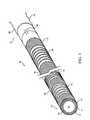
- FIG. 1is an illustration of a medical device.
- FIG. 2is a cross-sectional view of the device of FIG. 1 , taken along the distal end of the device.
- FIG. 3is a cross-sectional view of a medical device.
- FIG. 4is a cross-sectional view of a medical device.
- FIG. 5is an illustration of a medical device.
- FIG. 6is an illustration of a medical device.
- FIG. 7is an illustration of a medical device.
- FIG. 8is an illustration of a medical device.
- FIG. 9is an illustration of a balloon catheter.
- FIG. 10is an illustration of a medical device.
- FIG. 11is an illustration of a medical device.
- a medical device 20(as shown, a tubing or a catheter) includes an elongated shaft 22 and a conductive path 26 formed on the shaft.
- shaft 22has an exterior surface 28 and an interior surface 30 that defines a lumen 24 .
- Conductive path 26is disposed on exterior surface 28 and interior surface 30 , extending from a proximal end 32 to a distal end 34 of device 20 .
- conductive path 26includes a plurality of alternating solid portions or bands 36 and coil portions 38 extending on exterior surface 28 and along the length of shaft 22 .
- conductive path 26includes a capacitor 40 and terminates with an electrical lead 42 .
- conductive path 26extends across a conductive bridge 44 to interior surface 30 , where the conductive path includes a solid conductive portion 46 that serves as a return path for flowing current (described below). Solid portion 46 extends proximally and terminates with an electrical lead 48 . Leads 42 and 48 are capable of being connected to a current source (not shown).
- coil portions 38which acts as an inductor
- capacitor 40which together to the inductor forms an LC circuit
- MRImagnetic resonance imaging
- coil portions 38can appear as a characteristic pattern, such as a series of bright portions, that can be easily detected and distinguished by eye or by a detection system from surrounding body tissue.
- shaft 22can be formed of one or more materials, such as non-magnetic materials, that do not interfere with the MRI visibility of device 20 .
- the materialcan be visibly transparent or opaque.
- materialsinclude polymers, such as, for example, polypropylene, polyethylene (such as high density polyethylene), polysulfonate, polyamide (e.g., Nylon), polyethyleneterephthalate (PET), polytetrafluoroethylene (PTFE), polyacetonitrile, polymer-amorphous carbon composites, and polymer-carbon nanotube composites.
- the polymerscan be extruded to form a flexible shaft that can navigate a tortuous path.
- Non-polymer materialsinclude ceramics, glass, or non-ferromagnetic metals, such as aluminum and titanium.
- conductive path 26includes a thin coating of one or more conductive materials.
- materialsinclude conductive polymers, such as polyaniline, polypyrrole, or poly(ethylene-dioxythiophene) (PEDT), and conductive carbon (e.g., graphite). Syntheses of conductive polymers are described in the literature. Conductive polymers are also available commercially, for example, polyaniline from Panipol (Porvoo, Finland), polyaniline- and polypyrrole-coated carbon powders as well as highly soluble emeraldine base (EB) from Eeonyx Corp., polypyrrole dispersions having different core materials from DSM, and PEDT from H. C. Starck.
- conductive polymerssuch as polyaniline, polypyrrole, or poly(ethylene-dioxythiophene) (PEDT), and conductive carbon (e.g., graphite). Syntheses of conductive polymers are described in the literature. Conductive polymers are also available commercially, for example, polyaniline
- Other materialsinclude metals having low magnetic susceptibility, such as copper, silver, gold, platinum, tungsten, tantalum, titanium, or alloys of these materials.
- the materialcan be radiopaque, e.g., visible by X-ray fluoroscopy. Examples of radiopaque materials include tantalum, tungsten, gold, platinum, palladium, or their alloys.
- the coating of material(s)can have a thickness of about ten nanometers to about 20 micrometers, although larger thicknesses can be formed. By forming the coating thin, the conductive path can be formed to enhance the MRI visibility of device 20 , while not compromising (e.g., degrading) the mechanical properties of the device. In certain cases, such as balloon catheters, having a relatively thick coating can increase the rigidity of the catheter. As a result, the catheter may not be able to travel well through a narrow and tortuous path.
- Conductive path 26can be formed using any of a variety of techniques. For example, certain conductive polymers can be dissolved in an organic solvent or dispersed in aqueous or non-aqueous media, and then applied (e.g., casted, sprayed or painted) to form a pre-selected pattern. Other techniques include plating, dipping, spraying, sputtering, plasma deposition, chemical vapor deposition, physical vapor deposition, or pulse laser deposition (PLD).
- PLDpulse laser deposition
- Selected patterns of conductive path 26can be formed, for example, by covering selected portions of shaft 22 with a mask (such as an adhesive tape or a dissolve material (e.g., polysaccharide, gelatin, or polyvinyl alcohol (PVA))) prior to forming the conductive path, and subsequently removing the mask after the path is formed.
- a masksuch as an adhesive tape or a dissolve material (e.g., polysaccharide, gelatin, or polyvinyl alcohol (PVA))
- PVApolyvinyl alcohol
- Another techniqueis to form a complete, uniform coating and subsequently remove selected areas to form conductive path 26 , e.g., using excimer laser ablation.
- Another techniqueis to use conductive polymeric fibers or textile to form conductive path 26 .
- conductive path 26can be formed.
- a conductive layer 52e.g., a conductive polymer or conductive carbon
- an insulating layer 54can be applied to conductive layer 52 .
- Insulating layer 54can include a polymer (e.g., a heat shrink polymer such as a polyolefin, polytetrafluoroethylene (PTFE), polyamide (e.g., Nylon), polyvinyl chloride (PVC), or polyterephthalate (PET)) or a ceramic.
- Conductive path 26can be completed by forming bands 36 and coil portions 38 on insulating layer 54 .
- bands 36 and/or coil portions 38can be covered, e.g., with a protective polymer coating, to prevent damage to conductive path 26 .
- Conductive layer 52 or solid portion 46can cover substantially all of their respective adjacent surfaces or only a portion thereof, e.g., as a stripe extending to proximal end 32 .
- solid portion 46can be replaced with a conductive wire 50 (e.g., a copper wire) that extends along the length of shaft 22 (e.g., from distal end 34 to proximal end 32 to lead 48 ).
- Wire 50can be embedded in shaft 22 (as shown) or be disposed on (e.g., glued to) interior surface 30 .
- Wire 50 , or a stripe of solid portion 46 or conductive layer 52can extend linearly or helically (e.g., counter to the direction of coil portions 38 ) to proximal end 32 .
- a conductive pathdoes not include any bands.
- one coil portion 38can extend the entire length of a device or at a selected portion of the device.
- Multiple, spaced coil portions 38can extend the entire length of a device or at selected portions of the device.
- the length (L) of coil portions 38 and/or bands 36can be same or different (as shown in FIG. 6 ).
- the spacing between coil portions 38 and/or bands 36can be the same or different.
- Different configurations of bands and/or coil portionscan affect the mechanical properties (such as flexibility and resistance to kinking) of the medical device.
- bridge 44To form a complete circuit, bridge 44 , capacitor 40 , and leads 42 and 48 are connected to conductive path 26 .
- Bridge 44can be formed using an electrically conducting epoxy or by applying one or more of the electrically conducting materials described above using any of the above techniques.
- An example of capacitor 40is one having a capacitance of about 10.2 pF for a circuit to resonate at 64 mHz with an inductance, L, of about 6 ⁇ 10 ⁇ 7 Henry.
- capacitor 40is a fractal capacitor (e.g., as described in Samavati et al., “Fractal Capacitors” IEEE Journal of Solid - State Circuits , Vol. 33, No. 12, December 1998, p.
- Capacitor 40can be a component of the current source. Capacitor 40 , such as those available from Fractus, S. A. (Barcelona, Spain), can be attached (e.g., glued) to device 20 near proximal end 32 and electrically connected to conductive path 26 .
- the LC circuitcan be a serial LC circuit or a parallel LC circuit. In some cases, a resistor is included in the LC circuit to lower the Q-value and broaden the magnetic resonance signal generated by the conductive path 105 .
- Leads 42 and 48can be connected to conductive path 26 at proximal end 32 using, for example, a conductive epoxy or solder.
- device 20is inserted into a subject (e.g., a human patient), and the subject is placed into an MRI system.
- the MRI systemis capable of imaging the subject (e.g., body tissue) according to conventional methods, as described, for example, in U.S. Pat. No. 6,280,385.
- a currentis passed through conductive path 26 , for example, sequentially or simultaneously with the pulsing of the incident radio waves.
- the currentAs current is passed through the circuit, in particular, through coil portions 38 , the current induces a local magnetic field in the coil portions.
- the magnetic fieldgenerates a magnetic resonance signal (e.g., equal to the resonance frequency of the applied field from the MRI system) that can be detected processed by the MRI system.
- the MRI systemis capable of processing the signals from device 20 and from the subject, superimposing the signals, and generating an image of both the device and the subject, thereby providing a real time indication of the position of device 20 .
- the amount of current appliedcan be varied to enhance the visibility of device 20 according to the MRI system or sequence being used.
- the LC circuitcan also be tuned to change the resonance frequency of the loop circuit and facilitate detection of device 20 over a range of magnetic field strengths (e.g., 0.5 T, 1.5 T, and 3.0 T).
- the resonance frequencycan be changed by adding or removing one or more additional capacitors connected between leads 42 and 48 , in parallel with capacitor 40 .
- the additional capacitor(s)can be a part of one or more modular units adapted to engage (e.g., click and lock) with the proximal end of the catheter.
- the resonance frequencycan be changed by short circuiting one or more coil portions 38 (e.g., with a conductive strip).
- a coil portioncan be short circuited by contacting (e.g., sliding) a tube or C-clamp having a conductive inner surface over the coil portion. As the tube or C-clamp is slid over the coil portion, portions of (or the entire) coil portion is short circuited, which changes the inductance of the coil portion and the overall LC resonance frequency.
- the short circuitingcan occur incrementally as a function of the number of windings in a coil portion, e.g., in ten discrete steps for a coil portion having ten windings.
- the tube or C-clampincludes an inner surface having a conductive coil of different pitch than the windings of the underlying coil portion. Sliding the tube or C-clamp over a coil portion short circuits only parts of the coil portion, thereby allowing the inductance of the coil portion to be changed in finer increments.
- the capacitor(s) described hereincan be microelectromechanical systems (MEMS) tunable capacitor(s).
- MEMS tunable capacitorsare described, for example, in Zou et al., Development of a Wide Tuning Range MEMS Tunable Capacitor for Wireless Communications Systems , Technical Digest—International Electron Devices Meeting 2000. p. 403-406.
- the MEMS tunable capacitorallows the capacitance value of the capacitor to be changed automatically.
- the information from an MRI imagecan be used by a processor to directly update the capacitor continuously to enhance the resonance frequency of the system.
- the MRI systemcan detune or tune the LC circuit to enhance the visibility of the catheter by enhancing the contrast in real time.
- a direct currentis passed through conductive path 26 that induces a magnetic field, which disturbs the local spin behavior to provide a detectable signal.
- the radio wave pulses from the MRI systemcan cause the LC circuit to resonate at the magnetic resonance frequency, thereby providing a passive (i.e., no applied current) method of imaging device 20 , as described in Melzer, et al., U.S. Pat. No. 6,280,385.
- a passive (i.e., no applied current) method of imaging device 20as described in Melzer, et al., U.S. Pat. No. 6,280,385.
- a magnetic fieldis induced within the coil portions.
- the induced magnetic fieldin turn generates an eddy current that flows to capacitor 40 , where the current is temporarily stored.
- the current stored in capacitor 40flow to coil portions 38 , where the current now produces a local magnetic field with a magnetic resonance signal (e.g., at the magnetic resonance frequency of the MRI system).
- the MRI systemis capable of detecting the signal from the LC circuit, processing the data to provide an image of device 20 , and superimposing the images of the device and the subject to produce an image of the device in the subject on a visual display. As a result, real time imaging of device 20 can be performed.
- device 20does not include a capacitor.
- device 20can include one or more agents that can further enhance MRI visibility, and/or enhance fluoroscopic and/or ultrasound visibility of the device.
- the agentsometimes called a contrast agent, can be in the form of, e.g., a neat liquid, particles, a solution, a hydrogel, or an emulsion.
- the agentcan have an MRI response that is different than the MRI response of the medical device in which the contrast agent is used, and/or the MRI response of the bodily tissue or fluid near the contrast agent during use.
- the MRI responseis the response to a magnetic field or radio waves used during MRI.
- the contrast agentincludes one or more materials having a T 1 relaxation time that is different than that of the medical device and/or tissue.
- the contrast agentcan include a material that appears bright in an MRI image, such as a solution having a T 1 (longitudinal) relaxation time shortening agent and a proton-containing fluid, such as water or glycerin.
- T 1 relaxation time shortening agentsinclude a paramagnetic metal salt or a paramagnetic metal chelate compound, such as heavy metal complexes, e.g., gadolinium diethylenetriaminepentaacetic acid (e.g., a 1% Gd-DTPA aqueous solution), GdDTPA-BMA, and GdHP-D03A (e.g., available from Schering, Nycomed and Bracco under the trade marks MAGNEVIST®, OMNISCAN®, and PROHANCE®).
- a paramagnetic metal salt or a paramagnetic metal chelate compoundsuch as heavy metal complexes, e.g., gadolinium diethylenetriaminepentaacetic acid (e.g.,
- the contrast agentcan include one or more materials that produce a magnetic susceptibility artifact (i.e., an artifact marker that appears dark in an MRI image).
- the materialcan have a T2 relaxation time that is different than that of the medical device and/or tissue.
- the contrast agentcan include a carrier or a fluid having ferromagnetic, ferrimagnetic, or superparamagnetic nanoparticles, such as iron oxide, dysprosium oxide, and/or gadolinium oxide.
- the particlescan be surface modified, e.g., made hydrophilic, to suspend the particles in the fluid and reduce the occurrence of precipitation and/or coagulation. Examples of particles and methods of modifying the particles are described in U.S. Pat. Nos. 6,123,920 and 6,423,296, hereby incorporated by reference.
- a magnetic susceptibility artifactcan also be introduced into the MRI image by including an air-filled cavity in the medical device, e.g., in shaft 22 .
- the contrast agentcan be embedded into shaft 22 .
- the contrast agentcan be encapsulated in hollow members, such as hollow fibers, and dispersed in the shaft as described in commonly-assigned U.S. Ser. No. 10/390,202, filed Mar. 17, 2003.
- the contrast agentcan be contained in a cavity or a lumen defined by the medical device, and/or by supported on a porous material, such as a ceramic material (e.g., aluminum oxide, titanium oxide, or a zeolite).
- Solid contrast agentscan be blended into a structural material of device 20 (e.g., a polymer of shaft 22 ) and extruded to form the device.
- the contrast agentcan be applied directly to the surface of the device, e.g., as a neat material or in the presence of solvent.
- the contrast agentcan be mixed with an adhesive (such as a polyurethane adhesive) and applied to the surface as a coating, e.g., from about 50 to about 300 microns thick.
- the MRI contrast agentcan be incorporated into a coating composition and coated onto a surface of the medical device.
- the coatingcan be on an interior surface and/or on the exterior surface of a medical device. Forming the coating on an interior surface can reduce loss of the contrast agent by fluid exchange (e.g., with bodily fluid), thereby enhancing the effective lifetime of the contrast agent.
- the contrast agentcan be incorporated into a coating using methods such as compounding or blending.
- the coating compositioncan include a lubricous, hydrophilic and/or hydrogel material used to improve biocompatibility and to aid insertion of the device through the body.
- Hydrophilic and hydrogel polymersinclude, e.g., polyethylene oxide, polypropylene oxide, polyvinyl-pyrrolidone, polycarboxylic acid, cellulosic polymers, gelatin, maleic anhydride polymers, polysaccharides, polyvinyl alcohol, polyacrylic acid, hyaluronic acid, collagen, and poly(2-hydroxyethyl methacrylate) (polyHEMA).
- Gd-DTPAcan be dissolved in water and mixed with a 1% polyacrylic acid/polyacrylamide hydrogel solution.
- the mixture(a hydrogel/Gd-DTPA complex) can be attached to a device by covalent bonding.
- Such methodsare described in U.S. Ser. No. 09/995,528, filed Nov. 27, 2001.
- Methods for applying coatings to medical devicesinclude, for example, dip coating and spraying.
- the surface of the medical devicemay be pre-treated in order to affix the coating to the surface of the device and/or enhance the hydrophilicity of plastic substrates prior to coating.
- Surface treatment techniquesinclude, e.g., plasma activation, silanization, and treating the surface with a primer solution.
- Hydrophilic polymerscan be integrated or attached to the device by co-extruding with the shaft.
- the polymer of the shaftprovides desirable mechanical properties while the hydrophilic polymer loaded with a contrast agent provides magnetic resonance contrast.
- Chemical and/or physical cross-linking of the coatingmay be used, depending on the type of coating, to prevent the coating from sloughing off or leaching from the surface of the device during insertion and/or contact with the surrounding body fluids.
- Cross-linkingcan be achieved, for example, by using chemical or radiation-based (e.g., photochemical and electron beam) techniques.
- the coatingincludes a releasable therapeutic agent, a drug, or a pharmaceutically active compound.
- agentsinclude antithrombogenic agents, antiproliferative agents, antioxidants, anti-inflammatory agents, anesthetic agents, anti-coagulants, and antibiotics.
- Other agents, drugs, and compoundsare described in U.S. Ser. No. 10/232,265, filed Aug. 30, 2002.
- the contrast agentscan be formed on a medical device (such as shaft 22 ) in a predetermined sequence that can be easily recognized and distinguished from the surrounding body tissue under MRI, for example, using a pattern recognition system such as a pattern recognition software integrated in MRI software by the manufacturer.
- a device 100can include a series of bands 102 having a T 1 relaxation time shortening agent alternating with a series of bands 104 having a susceptibility artifact generating material, i.e., in an AB sequence that gives a characteristic alternating bright and dark MRI image.
- the devicecan have a portion with no contrast agent that would produce an absence of an MRI signal (i.e., a signal void) because of displaced bodily fluid.
- Sequences such as ABA, BAB, ABBA, or ABCare possible, where A can be a T 1 relaxation time shortening agent, B can be an artifact generating material or a signal void, and C is a marker or contrast agent different than A or B.
- MRI contrast agentscan also be included in a medical device having the conductive path or LC circuit described above.
- a device 106includes an electrically conductive path 105 that extends spirally about a portion of the shaft 110 .
- a plurality of marker bands 112 and 114are arranged along the length of the catheter shaft 110 .
- Marker bands 112include a magnetic susceptibility artifact marker, and marker band 114 includes a T 1 enhancing material. Marker bands 112 and 114 can be arranged in a characteristic pattern as described above.
- device 106can be monitored using different visualization techniques, thereby enhancing the versatility of the device.
- device 106includes one or more signal void portions and/or one of the other types of contrast agents described below.
- the devices described hereincan include other types of contrast agents, such as those visible by X-ray fluoroscopy (i.e., a radiopaque material) and/or ultrasound spectroscopy.
- radiopaque materialsinclude tantalum, tungsten, platinum, palladium, or gold.
- the radiopaque materialcan be placed inside an encapsulating member (for example, as described in U.S. Ser. No. 10/390,202) and/or compounded with the material of the medical device.
- the radiopaque materiale.g., a band of radiopaque material, can be placed on a medical device at selected positions to make up a characteristic pattern.
- the ultrasound contrast agentcan be any material that enhances visibility during ultrasound imaging.
- An ultrasound contrast agentcan include a suspension having trapped bubbles of sufficient size to deflect sound waves.
- any of the medical devices described abovecan include a coiled portion or an inductive element, an MRI contrast agent, a radiopaque material, and/or an ultrasound contrast agent, in any combination or arrangement (e.g., ABCD or ABCDE).
- a combination of inductive elements, MRI contrast agents, ultrasound contrast agents, and/or radiopaque materialscan offer the flexibility of visualizing a medical device under a variety of imaging conditions.
- the tubing described abovecan be sized and shaped to form other devices.
- device 20can be attached to a medical balloon 200 to form into a balloon catheter (e.g., as described in commonly-assigned U.S. Ser. No. 10/263,225, filed Oct. 2, 2002, and entitled “Medical Balloon”; Anderson U.S. Pat. No. 6,120,364; Wang U.S. Pat. No. 5,714,110; and Noddin U.S. Pat. No. 4,963,313).
- Coil portions 38can be used, for example, as markers that indicate the position of the balloon upon full inflation.
- Other examples of catheters into which the tubing can be formedinclude guide catheters (e.g., as described in U.S.
- tubingcan be formed into an introducer sheath or a restraining sheath for a stent delivery system, for example, as described in U.S. Pat. No. 6,488,694. Methods of making tubing are described, for example, in U.S. Ser. No. 10/645,014, filed Aug. 21, 2003.
- the conductive path and/or marker(s)can be incorporated into a guidewire, such as a polymeric guide wire.
- a guidewiresuch as a polymeric guide wire.
- Some metal guide wirescan absorb energy from the high power radiowave frequency energy used during MRI procedures. As a result, some metal guide wires can become hot, which can limit their use in MRI applications.
- Polymeric guide wiresin comparison, do not exhibit localized heating under MRI. Methods of making polymeric guide wires, including examples of materials, are described in U.S. Pat. No. 6,436,056, and U.S. Ser. No. 10/645,014, filed Aug. 21, 2003.
- the guidewireincludes a biocompatible polymer, such as polyethylene, e.g., high-density polyethylene (HDPE), which can form fibers having a good mechanical profile.
- the HDPE polymercan have an average molecular weight (M w ) of about 400,000 g/mol, and a molecular weight distribution (i.e., polydispersity) of about 3 to 7, for example, a polydispersity of about 5.
- the polymercan have a high molecular weight tail (e.g., 0-10% content of greater than about 1,000,000) to ensure the formation of extended chain crystals.
- a minimal amount ( ⁇ 0.1%) of low molecular weight (e.g., 4000 g/mol or less) fractionis preferred to prevent the premature onset of relaxation processes in the melt and to ensure force transfer during extrusion of the melt through a die.
- Low molecular weight fractionscan be removed by extraction in an appropriate solvent (e.g., hexane) to increase the tensile module of the resulting fiber.
- an appropriate solvente.g., hexane
- Examples of HDPEsare commercially available from, e.g., BASELL (BASF) Corporation under the trade designation LUPULEN 52 ZHI; Chevron Philips Corporation under the trade designation MARLEX TR-751; and Solvay Corporation under the trade designations RIGIDEX HM5420 XPH, AH 5493, and BH 5363.
- a polymeric guide wirecan be prepared, for example, by extrusion.
- the polymercan be extruded to form relatively stiff fibers having the requisite mechanical properties (e.g., Young's modulus (E) of greater than about 10 GPa and a tensile strength of greater than about 0.5 GPa).
- HDPE fiberscan be prepared by solid-state extrusion of melt crystallized spherulitic polyethylene or by drawing solution crystallized gel films (e.g., performed by DSM (Heerlen, The Netherlands) as a process marketed as the Dyneemag Process).
- DSMHeerlen, The Netherlands
- An alternative processinvolves melt deformation of HDPE under controlled conditions to obtain highly oriented fibers.
- the processinvolves chain extension of the high molecular weight fraction of HDPE having a linear macromolecular structure during flow just above the solidification temperature, followed by crystallization (e.g., of a high molecular weight fraction) and by co-crystallization e.g., of a low molecular weight fraction) of the remaining material.
- the polymercan be extruded at a temperature close to the crystallization temperature (e.g., a self-blocking temperature, which can be indicated by an extrusion pressure rise, e.g., upward from about 3500 psi) and at a strain rate of about 10 3 s ⁇ 1 to solidify the deformed macromolecules before relaxation occurs.
- crystallizationoccurs from about T g +30 to about T m ⁇ 10 (e.g., from about 140 to about 160° C.).
- Such processing conditionscan create an elongated, interlocking morphology that displays exceptional mechanical properties (e.g., a Young's modulus (E) of between about 10-80 GPa and a tensile strength of about 1.2 GPa).
- EYoung's modulus
- the fibrilscan make up about 5% of the extruded material and can have a diameter of between about 5-25 nm with an aspect ratio of about 200-600.
- the bulk materialcan be characterized as a lamellar overgrowth chain direction like in the fibrils.
- the extrusion headcan be equipped with a pressure transducer and a thermocouple to control pressure and temperature during extrusion. Additional information regarding HDPEs is described in Bashir, Z., et al., J. Mat. Science, 19 (1984), 3713 ; and Bashir, Z., et al., J. Mat. Science, 19 (1986), 3993 .
- the extrusion headis equipped with one or more transducers or vibrators.
- Vibratory energye.g., ultrasonic vibrations
- Vibratory energycan allow the extrusion temperature to be lowered by reducing friction between the polymer melt and the surface of the extrusion head.
- Examples of vibratorsinclude mechanical transducers (e.g., spring mass/moving coil systems) or solid state transducers such as those having piezoelectric elements, available, e.g., from STAPLA Ultrasonics Corp. (Wilmington, Mass.) and Blatek Inc. (State College, Pa.).
- This exampleestimates how much field disturbance may be needed to make a visible marker.
- the magnetic fieldis created inside the coil portion and outside the coil portion along the direction of the axis of the coil. Since the polymer of the catheter is creating a void, the visible material by MRI is the water inside of the catheter.
- the field created inside the coilis 5.167 ⁇ 10 ⁇ 6 T relative to the field outside the coil. So, for a coil having a length of five mm and wherein the width of the individual conductive paths is 100 micrometer, with a spacing of 50 micrometers (i.e., 33 windings over 5 mm gives a N/L of 6600), a current of 0.62 mA can be applied to obtain the targeted field.
- a medical devicecan include portions capable of generating a field at an angle with the catheter axis.
- FIGS. 10 and 11show examples of coil portions capable of generating fields that can extend outside of the catheter tube and change the spin behavior, for example, of the water or blood, outside the catheter.
- a magnetic field of 5.167 ⁇ 10 ⁇ 6 Tesla 0.8 mm outside the catheter tubeis preferably created.
Landscapes
- Health & Medical Sciences (AREA)
- Life Sciences & Earth Sciences (AREA)
- General Health & Medical Sciences (AREA)
- Hematology (AREA)
- Biophysics (AREA)
- Anesthesiology (AREA)
- Biomedical Technology (AREA)
- Heart & Thoracic Surgery (AREA)
- Pulmonology (AREA)
- Animal Behavior & Ethology (AREA)
- Engineering & Computer Science (AREA)
- Public Health (AREA)
- Veterinary Medicine (AREA)
- Physics & Mathematics (AREA)
- Pathology (AREA)
- Condensed Matter Physics & Semiconductors (AREA)
- General Physics & Mathematics (AREA)
- Magnetic Resonance Imaging Apparatus (AREA)
Abstract
Description
B=I·(N/L)·μo
where μois the permeability in a vacuum [(μo)=12.566370614×10⁻⁷H/m (of N/A2)]; I is current in Ampere; and (N/L) is the number of windings per meter. Assuming that the artifact to be induced to be visible is similar to or greater than a typical fat-water chemical shift of 220 Hz at 1.5 T, then the field created inside the coil is 5.167×10⁻⁶T relative to the field outside the coil. So, for a coil having a length of five mm and wherein the width of the individual conductive paths is 100 micrometer, with a spacing of 50 micrometers (i.e., 33 windings over 5 mm gives a N/L of 6600), a current of 0.62 mA can be applied to obtain the targeted field.
Bz=0=μoI/(2R)
where μois the permeability in a vacuum [(μ0)=12.566370614×10⁻⁷H/m (of N/A2)]; I is current in Ampere; and R is the radius of the loop.
where b is the radius of the loop; z is the point of interest along the z-axis; and Brelis the ratio of the magnetic field at the point interest to the maximum magnetic field.
Claims (1)
Priority Applications (4)
| Application Number | Priority Date | Filing Date | Title |
|---|---|---|---|
| US10/763,690US8620406B2 (en) | 2004-01-23 | 2004-01-23 | Medical devices visible by magnetic resonance imaging |
| PCT/US2005/000315WO2005073745A1 (en) | 2004-01-23 | 2005-01-06 | Medical devices visible by magnetic resonance imaging |
| EP05705103AEP1709457B1 (en) | 2004-01-23 | 2005-01-06 | Medical devices visible by magnetic resonance imaging |
| AT05705103TATE546740T1 (en) | 2004-01-23 | 2005-01-06 | MEDICAL FACILITIES VISIBLE THROUGH MAGNETIC RESONANCE IMAGING |
Applications Claiming Priority (1)
| Application Number | Priority Date | Filing Date | Title |
|---|---|---|---|
| US10/763,690US8620406B2 (en) | 2004-01-23 | 2004-01-23 | Medical devices visible by magnetic resonance imaging |
Publications (2)
| Publication Number | Publication Date |
|---|---|
| US20050165301A1 US20050165301A1 (en) | 2005-07-28 |
| US8620406B2true US8620406B2 (en) | 2013-12-31 |
Family
ID=34795105
Family Applications (1)
| Application Number | Title | Priority Date | Filing Date |
|---|---|---|---|
| US10/763,690Expired - Fee RelatedUS8620406B2 (en) | 2004-01-23 | 2004-01-23 | Medical devices visible by magnetic resonance imaging |
Country Status (4)
| Country | Link |
|---|---|
| US (1) | US8620406B2 (en) |
| EP (1) | EP1709457B1 (en) |
| AT (1) | ATE546740T1 (en) |
| WO (1) | WO2005073745A1 (en) |
Cited By (4)
| Publication number | Priority date | Publication date | Assignee | Title |
|---|---|---|---|---|
| US11204399B2 (en)* | 2014-11-12 | 2021-12-21 | Sunnybrook Research Institute | System and method for device tracking via magnetic resonance imaging with light-modulated magnetic susceptibility markers |
| US11202888B2 (en) | 2017-12-03 | 2021-12-21 | Cook Medical Technologies Llc | MRI compatible interventional wireguide |
| EP4475752A1 (en)* | 2022-02-07 | 2024-12-18 | Anttila, Eric, D. | Medical systems, devices, and kits useful in performing treatment under magnetic resonance imaging and related methods |
| US20250186128A1 (en)* | 2022-02-07 | 2025-06-12 | Cook Medical Technologies Llc | Medical Devices for Interventional MRI |
Families Citing this family (109)
| Publication number | Priority date | Publication date | Assignee | Title |
|---|---|---|---|---|
| WO2003002243A2 (en) | 2001-06-27 | 2003-01-09 | Remon Medical Technologies Ltd. | Method and device for electrochemical formation of therapeutic species in vivo |
| US7722578B2 (en)* | 2004-09-08 | 2010-05-25 | Boston Scientific Scimed, Inc. | Medical devices |
| US20060105016A1 (en)* | 2004-11-12 | 2006-05-18 | Gray Robert W | Device compatible with magnetic resonance imaging |
| DE102005000761B4 (en)* | 2005-01-04 | 2008-05-21 | Siemens Ag | Intracorporeal endolocular coil for recording magnetic resonance signals |
| EP1843810A1 (en)* | 2005-01-14 | 2007-10-17 | Micronix Pty Ltd | Guiding insert assembly for a catheter used with a catheter position guidance system |
| US20070021667A1 (en)* | 2005-05-19 | 2007-01-25 | Biophan Technologies, Inc. | Electromagnetic resonant circuit sleeve for implantable medical device |
| US7778684B2 (en)* | 2005-08-08 | 2010-08-17 | Boston Scientific Scimed, Inc. | MRI resonator system with stent implant |
| US8784336B2 (en) | 2005-08-24 | 2014-07-22 | C. R. Bard, Inc. | Stylet apparatuses and methods of manufacture |
| US20070100279A1 (en)* | 2005-11-03 | 2007-05-03 | Paragon Intellectual Properties, Llc | Radiopaque-balloon microcatheter and methods of manufacture |
| CA2623616A1 (en) | 2005-11-29 | 2007-06-07 | Surgi-Vision, Inc. | Mri-guided localization and/or lead placement systems, related methods, devices and computer program products |
| US8457712B2 (en)* | 2005-12-30 | 2013-06-04 | Wisconsin Alumni Research Foundation | Multi-mode medical device system and methods of manufacturing and using same |
| US20070156042A1 (en)* | 2005-12-30 | 2007-07-05 | Orhan Unal | Medical device system and method for tracking and visualizing a medical device system under MR guidance |
| US7957789B2 (en)* | 2005-12-30 | 2011-06-07 | Medtronic, Inc. | Therapy delivery system including a navigation element |
| US8840660B2 (en) | 2006-01-05 | 2014-09-23 | Boston Scientific Scimed, Inc. | Bioerodible endoprostheses and methods of making the same |
| US8089029B2 (en) | 2006-02-01 | 2012-01-03 | Boston Scientific Scimed, Inc. | Bioabsorbable metal medical device and method of manufacture |
| US20070239256A1 (en)* | 2006-03-22 | 2007-10-11 | Jan Weber | Medical devices having electrical circuits with multilayer regions |
| US8048150B2 (en) | 2006-04-12 | 2011-11-01 | Boston Scientific Scimed, Inc. | Endoprosthesis having a fiber meshwork disposed thereon |
| US7933662B2 (en) | 2006-04-26 | 2011-04-26 | Marshall Mark T | Medical electrical lead including an inductance augmenter |
| US7467007B2 (en)* | 2006-05-16 | 2008-12-16 | Siemens Medical Solutions Usa, Inc. | Respiratory gated image fusion of computed tomography 3D images and live fluoroscopy images |
| US8233962B2 (en)* | 2006-05-16 | 2012-07-31 | Siemens Medical Solutions Usa, Inc. | Rotational stereo roadmapping |
| DE102006034389B4 (en)* | 2006-07-25 | 2018-06-07 | Siemens Healthcare Gmbh | Catheter for use in magnetic resonance assisted interventional procedures |
| EP2054537A2 (en) | 2006-08-02 | 2009-05-06 | Boston Scientific Scimed, Inc. | Endoprosthesis with three-dimensional disintegration control |
| JP2010503489A (en) | 2006-09-15 | 2010-02-04 | ボストン サイエンティフィック リミテッド | Biodegradable endoprosthesis and method for producing the same |
| EP2959925B1 (en) | 2006-09-15 | 2018-08-29 | Boston Scientific Limited | Medical devices and methods of making the same |
| WO2008034066A1 (en) | 2006-09-15 | 2008-03-20 | Boston Scientific Limited | Bioerodible endoprostheses and methods of making the same |
| WO2008034047A2 (en) | 2006-09-15 | 2008-03-20 | Boston Scientific Limited | Endoprosthesis with adjustable surface features |
| ES2357661T3 (en) | 2006-09-15 | 2011-04-28 | Boston Scientific Scimed, Inc. | BIOEROSIONABLE ENDOPROOTHESIS WITH BIOESTABLE INORGANIC LAYERS. |
| WO2008036548A2 (en) | 2006-09-18 | 2008-03-27 | Boston Scientific Limited | Endoprostheses |
| US7794407B2 (en) | 2006-10-23 | 2010-09-14 | Bard Access Systems, Inc. | Method of locating the tip of a central venous catheter |
| US8388546B2 (en) | 2006-10-23 | 2013-03-05 | Bard Access Systems, Inc. | Method of locating the tip of a central venous catheter |
| US8532742B2 (en)* | 2006-11-15 | 2013-09-10 | Wisconsin Alumni Research Foundation | System and method for simultaneous 3DPR device tracking and imaging under MR-guidance for therapeutic endovascular interventions |
| US7991483B1 (en)* | 2006-12-21 | 2011-08-02 | Boston Scientific Neuromodulation Corporation | Implantable electrodes containing polyoxometalate anions and methods of manufacture and use |
| ES2506144T3 (en) | 2006-12-28 | 2014-10-13 | Boston Scientific Limited | Bioerodible endoprosthesis and their manufacturing procedure |
| US20080183070A1 (en)* | 2007-01-29 | 2008-07-31 | Wisconsin Alumni Research Foundation | Multi-mode medical device system with thermal ablation capability and methods of using same |
| US20080208039A1 (en)* | 2007-02-28 | 2008-08-28 | Wisconsin Alumni Research Foundation | System and method of performing therapeutic endovascular interventions |
| US8175677B2 (en)* | 2007-06-07 | 2012-05-08 | MRI Interventions, Inc. | MRI-guided medical interventional systems and methods |
| US8052745B2 (en) | 2007-09-13 | 2011-11-08 | Boston Scientific Scimed, Inc. | Endoprosthesis |
| EP2198317A2 (en)* | 2007-09-24 | 2010-06-23 | Boston Scientific Limited | Mri phase visualization of interventional devices |
| CA2700523A1 (en) | 2007-09-24 | 2009-04-02 | Surgivision, Inc. | Mri-guided medical interventional systems and methods |
| US8315689B2 (en) | 2007-09-24 | 2012-11-20 | MRI Interventions, Inc. | MRI surgical systems for real-time visualizations using MRI image data and predefined data of surgical tools |
| US10524691B2 (en) | 2007-11-26 | 2020-01-07 | C. R. Bard, Inc. | Needle assembly including an aligned magnetic element |
| US10751509B2 (en) | 2007-11-26 | 2020-08-25 | C. R. Bard, Inc. | Iconic representations for guidance of an indwelling medical device |
| US8781555B2 (en) | 2007-11-26 | 2014-07-15 | C. R. Bard, Inc. | System for placement of a catheter including a signal-generating stylet |
| US9636031B2 (en) | 2007-11-26 | 2017-05-02 | C.R. Bard, Inc. | Stylets for use with apparatus for intravascular placement of a catheter |
| US9521961B2 (en) | 2007-11-26 | 2016-12-20 | C. R. Bard, Inc. | Systems and methods for guiding a medical instrument |
| US10449330B2 (en) | 2007-11-26 | 2019-10-22 | C. R. Bard, Inc. | Magnetic element-equipped needle assemblies |
| US8849382B2 (en) | 2007-11-26 | 2014-09-30 | C. R. Bard, Inc. | Apparatus and display methods relating to intravascular placement of a catheter |
| US9649048B2 (en) | 2007-11-26 | 2017-05-16 | C. R. Bard, Inc. | Systems and methods for breaching a sterile field for intravascular placement of a catheter |
| ES2465915T3 (en) | 2007-11-26 | 2014-06-09 | C.R. Bard, Inc. | Integrated system for intravascular catheter placement |
| US8478382B2 (en) | 2008-02-11 | 2013-07-02 | C. R. Bard, Inc. | Systems and methods for positioning a catheter |
| US7998192B2 (en) | 2008-05-09 | 2011-08-16 | Boston Scientific Scimed, Inc. | Endoprostheses |
| US8236046B2 (en) | 2008-06-10 | 2012-08-07 | Boston Scientific Scimed, Inc. | Bioerodible endoprosthesis |
| US8187221B2 (en)* | 2008-07-11 | 2012-05-29 | Nexeon Medsystems, Inc. | Nanotube-reinforced balloons for delivering therapeutic agents within or beyond the wall of blood vessels, and methods of making and using same |
| US7985252B2 (en) | 2008-07-30 | 2011-07-26 | Boston Scientific Scimed, Inc. | Bioerodible endoprosthesis |
| US9901714B2 (en) | 2008-08-22 | 2018-02-27 | C. R. Bard, Inc. | Catheter assembly including ECG sensor and magnetic assemblies |
| US8382824B2 (en) | 2008-10-03 | 2013-02-26 | Boston Scientific Scimed, Inc. | Medical implant having NANO-crystal grains with barrier layers of metal nitrides or fluorides |
| US8437833B2 (en) | 2008-10-07 | 2013-05-07 | Bard Access Systems, Inc. | Percutaneous magnetic gastrostomy |
| EP2403546A2 (en) | 2009-03-02 | 2012-01-11 | Boston Scientific Scimed, Inc. | Self-buffering medical implants |
| WO2010144402A2 (en) | 2009-06-08 | 2010-12-16 | Surgivision, Inc. | Mri-guided surgical systems with preset scan planes |
| JP5795576B2 (en) | 2009-06-12 | 2015-10-14 | バード・アクセス・システムズ,インコーポレーテッド | Method of operating a computer-based medical device that uses an electrocardiogram (ECG) signal to position an intravascular device in or near the heart |
| US9532724B2 (en) | 2009-06-12 | 2017-01-03 | Bard Access Systems, Inc. | Apparatus and method for catheter navigation using endovascular energy mapping |
| CN102625670B (en) | 2009-06-16 | 2015-07-15 | 核磁共振成像介入技术有限公司 | MRI-guided devices and MRI-guided interventional systems that can track and generate dynamic visualizations of the devices in near real time |
| EP2464407A4 (en) | 2009-08-10 | 2014-04-02 | Bard Access Systems Inc | Devices and methods for endovascular electrography |
| WO2011044421A1 (en) | 2009-10-08 | 2011-04-14 | C. R. Bard, Inc. | Spacers for use with an ultrasound probe |
| WO2011097312A1 (en) | 2010-02-02 | 2011-08-11 | C.R. Bard, Inc. | Apparatus and method for catheter navigation and tip location |
| US8668732B2 (en) | 2010-03-23 | 2014-03-11 | Boston Scientific Scimed, Inc. | Surface treated bioerodible metal endoprostheses |
| EP2912999B1 (en) | 2010-05-28 | 2022-06-29 | C. R. Bard, Inc. | Apparatus for use with needle insertion guidance system |
| EP4122385A1 (en) | 2010-05-28 | 2023-01-25 | C. R. Bard, Inc. | Insertion guidance system for needles and medical components |
| CN103228219B (en) | 2010-08-09 | 2016-04-27 | C·R·巴德股份有限公司 | Support and Covering Structures for Ultrasound Probe Heads |
| BR112013002431B1 (en) | 2010-08-20 | 2021-06-29 | C.R. Bard, Inc | SYSTEM FOR RECONFIRMING THE POSITION OF A CATHETER INSIDE A PATIENT |
| US8801693B2 (en) | 2010-10-29 | 2014-08-12 | C. R. Bard, Inc. | Bioimpedance-assisted placement of a medical device |
| US20120178076A1 (en)* | 2011-01-07 | 2012-07-12 | Hiroyuki Fujita | Magnetic resonance and non-magnetic resonance analysis |
| US8612021B2 (en) | 2011-02-10 | 2013-12-17 | Medtronic, Inc. | Magnetic resonance imaging compatible medical electrical lead and method of making the same |
| RU2609203C2 (en) | 2011-07-06 | 2017-01-30 | Си.Ар. Бард, Инк. | Determination and calibration of needle length for needle guidance system |
| USD724745S1 (en) | 2011-08-09 | 2015-03-17 | C. R. Bard, Inc. | Cap for an ultrasound probe |
| USD699359S1 (en) | 2011-08-09 | 2014-02-11 | C. R. Bard, Inc. | Ultrasound probe head |
| EP2754176A4 (en)* | 2011-09-08 | 2015-04-15 | Univ California | SENSOR FOR DETECTING A FORCE-NOISE LAW IN LIQUIDS |
| US9211107B2 (en) | 2011-11-07 | 2015-12-15 | C. R. Bard, Inc. | Ruggedized ultrasound hydrogel insert |
| US9408671B2 (en) | 2011-12-08 | 2016-08-09 | Parker Laboratories, Inc. | Biopsy grid |
| US10646552B2 (en) | 2012-01-17 | 2020-05-12 | Tyme, Inc. | Pharmaceutical compositions and methods |
| US10272068B2 (en) | 2012-01-17 | 2019-04-30 | Tyme, Inc. | Pharmaceutical compositions and methods |
| US20130183263A1 (en) | 2012-01-17 | 2013-07-18 | Steven Hoffman | Pharmaceutical compositions and methods |
| EP2861153A4 (en) | 2012-06-15 | 2016-10-19 | Bard Inc C R | Apparatus and methods for detection of a removable cap on an ultrasound probe |
| US10213130B2 (en)* | 2012-07-12 | 2019-02-26 | Siemens Healthcare Gmbh | Compressable catheter tip with image-based force sensing |
| US9585841B2 (en)* | 2013-10-22 | 2017-03-07 | Tyme, Inc. | Tyrosine derivatives and compositions comprising them |
| WO2015120256A2 (en) | 2014-02-06 | 2015-08-13 | C.R. Bard, Inc. | Systems and methods for guidance and placement of an intravascular device |
| US11714143B2 (en)* | 2014-04-24 | 2023-08-01 | Regents Of The University Of California | Omnidirectional MRI catheter resonator and related systems, methods and devices |
| DE102014218454A1 (en)* | 2014-09-15 | 2016-03-17 | Siemens Aktiengesellschaft | Apparatus, medical instrument and method for obtaining a spatial image of a medical instrument with a magnetic resonance tomography apparatus |
| US10973584B2 (en) | 2015-01-19 | 2021-04-13 | Bard Access Systems, Inc. | Device and method for vascular access |
| FR3033197A1 (en)* | 2015-02-26 | 2016-09-02 | Neelogy | HVDC MEASURING HEAD FOR MAGNETIC FIELD SENSOR |
| WO2016210325A1 (en) | 2015-06-26 | 2016-12-29 | C.R. Bard, Inc. | Connector interface for ecg-based catheter positioning system |
| US11000207B2 (en) | 2016-01-29 | 2021-05-11 | C. R. Bard, Inc. | Multiple coil system for tracking a medical device |
| US11344220B2 (en) | 2016-05-13 | 2022-05-31 | Becton, Dickinson And Company | Invasive medical device cover with magnet |
| US10327667B2 (en) | 2016-05-13 | 2019-06-25 | Becton, Dickinson And Company | Electro-magnetic needle catheter insertion system |
| US10980979B2 (en) | 2016-05-13 | 2021-04-20 | Becton, Dickinson And Company | Magnetic shield for medical devices |
| US11826522B2 (en) | 2016-06-01 | 2023-11-28 | Becton, Dickinson And Company | Medical devices, systems and methods utilizing permanent magnet and magnetizable feature |
| US10583269B2 (en) | 2016-06-01 | 2020-03-10 | Becton, Dickinson And Company | Magnetized catheters, devices, uses and methods of using magnetized catheters |
| US11116419B2 (en)* | 2016-06-01 | 2021-09-14 | Becton, Dickinson And Company | Invasive medical devices including magnetic region and systems and methods |
| US11413429B2 (en) | 2016-06-01 | 2022-08-16 | Becton, Dickinson And Company | Medical devices, systems and methods utilizing permanent magnet and magnetizable feature |
| US20170347914A1 (en) | 2016-06-01 | 2017-12-07 | Becton, Dickinson And Company | Invasive Medical Devices Including Magnetic Region And Systems And Methods |
| WO2018035000A1 (en)* | 2016-08-13 | 2018-02-22 | Ecom Medical, Inc. | Medical devices with layered conductive elements and methods for manufacturing the same |
| US10032552B2 (en) | 2016-08-30 | 2018-07-24 | Becton, Dickinson And Company | Cover for tissue penetrating device with integrated magnets and magnetic shielding |
| US10905497B2 (en) | 2017-04-21 | 2021-02-02 | Clearpoint Neuro, Inc. | Surgical navigation systems |
| US12178662B2 (en)* | 2017-05-23 | 2024-12-31 | Boston Scientific Scimed, Inc. | Catheter and spring element for contact force sensing |
| DE102018215618B3 (en)* | 2018-09-13 | 2019-12-05 | Siemens Healthcare Gmbh | Method for detecting a needle in magnetic resonance imaging |
| US10992079B2 (en) | 2018-10-16 | 2021-04-27 | Bard Access Systems, Inc. | Safety-equipped connection systems and methods thereof for establishing electrical connections |
| CN110018183A (en)* | 2019-03-22 | 2019-07-16 | 中车长春轨道客车股份有限公司 | A kind of anti-magnetosheath of bogie crossbeam steel pipe seam ray detection |
| US11590320B2 (en)* | 2019-04-04 | 2023-02-28 | Avent, Inc. | Two-in-one catheter and signal generating apparatus |
| CN113851253B (en)* | 2021-08-25 | 2024-11-22 | 复旦大学 | A magnetic resonance imaging compatible conductive paste composite and preparation method thereof |
Citations (24)
| Publication number | Priority date | Publication date | Assignee | Title |
|---|---|---|---|---|
| US4963313A (en) | 1987-11-30 | 1990-10-16 | Boston Scientific Corporation | Balloon catheter |
| US4985233A (en) | 1984-11-01 | 1991-01-15 | Nycomed /As | A diagnostic agent containing a non-radioactive paramagnetic metal species in a macromolecular carrier |
| US4989608A (en) | 1987-07-02 | 1991-02-05 | Ratner Adam V | Device construction and method facilitating magnetic resonance imaging of foreign objects in a body |
| US5154179A (en) | 1987-07-02 | 1992-10-13 | Medical Magnetics, Inc. | Device construction and method facilitating magnetic resonance imaging of foreign objects in a body |
| US5352431A (en) | 1991-10-04 | 1994-10-04 | Nihon Medi-Physics Co., Ltd. | Low molecular weight polysaccharide complexes for X-ray imaging |
| US5702682A (en) | 1995-12-01 | 1997-12-30 | Hercules Incorporated | Methods for preparing radiopaque medical devices |
| US5714110A (en) | 1993-09-20 | 1998-02-03 | Scimed Life Systems, Inc. | Process improvements for preparing catheter balloons |
| US5728079A (en) | 1994-09-19 | 1998-03-17 | Cordis Corporation | Catheter which is visible under MRI |
| US5744958A (en) | 1995-11-07 | 1998-04-28 | Iti Medical Technologies, Inc. | Instrument having ultra-thin conductive coating and method for magnetic resonance imaging of such instrument |
| US5817017A (en) | 1994-04-12 | 1998-10-06 | Pharmacyclics, Inc. | Medical devices and materials having enhanced magnetic images visibility |
| US6123920A (en) | 1996-01-10 | 2000-09-26 | Nycomed Imaging As | Superparamagnetic contrast media coated with starch and polyalkylene oxides |
| US6207134B1 (en) | 1994-09-27 | 2001-03-27 | Nycomed Imaging As | Ultrafine lightly coated superparamagnetic particles for MRI |
| US6264611B1 (en) | 1998-11-25 | 2001-07-24 | Ball Semiconductor, Inc. | Monitor for interventional procedures |
| US6280385B1 (en)* | 1997-10-13 | 2001-08-28 | Simag Gmbh | Stent and MR imaging process for the imaging and the determination of the position of a stent |
| WO2001075465A1 (en) | 2000-03-30 | 2001-10-11 | Case Western Reserve University | Mr invasive device and method for active mr guidance of invasive devices with target navigation |
| US6423296B1 (en) | 1996-01-10 | 2002-07-23 | Amersham Health As | Constrast media |
| US6436056B1 (en) | 1996-02-28 | 2002-08-20 | Boston Scientific Corporation | Polymeric implements for torque transmission |
| US6488694B1 (en) | 1991-01-28 | 2002-12-03 | Advanced Cardiovascular Systems, Inc. | Stent delivery system |
| US6503224B1 (en) | 1997-06-12 | 2003-01-07 | Scimed Life Systems, Inc. | Perfusion balloon catheter |
| US20030065267A1 (en) | 2001-09-28 | 2003-04-03 | Scimed Life Systems, Inc. | Systems and methods for magnetic resonance imaging elastography |
| US20030100830A1 (en)* | 2001-11-27 | 2003-05-29 | Sheng-Ping Zhong | Implantable or insertable medical devices visible under magnetic resonance imaging |
| US20030099764A1 (en) | 1998-05-26 | 2003-05-29 | Wisconsin Alumni Research Foundation | MR-signal emitting coatings |
| US6595952B2 (en) | 2001-01-04 | 2003-07-22 | Scimed Life Systems, Inc. | Guide catheter with backup support system |
| US20030185895A1 (en) | 2002-03-29 | 2003-10-02 | Janel Lanphere | Drug delivery particle |
Family Cites Families (1)
| Publication number | Priority date | Publication date | Assignee | Title |
|---|---|---|---|---|
| US10063995B2 (en) | 2015-12-28 | 2018-08-28 | T-Mobile Usa, Inc. | Control beacons for wireless devices |
- 2004
- 2004-01-23USUS10/763,690patent/US8620406B2/ennot_activeExpired - Fee Related
- 2005
- 2005-01-06EPEP05705103Apatent/EP1709457B1/ennot_activeExpired - Lifetime
- 2005-01-06WOPCT/US2005/000315patent/WO2005073745A1/enactiveApplication Filing
- 2005-01-06ATAT05705103Tpatent/ATE546740T1/enactive
Patent Citations (24)
| Publication number | Priority date | Publication date | Assignee | Title |
|---|---|---|---|---|
| US4985233A (en) | 1984-11-01 | 1991-01-15 | Nycomed /As | A diagnostic agent containing a non-radioactive paramagnetic metal species in a macromolecular carrier |
| US4989608A (en) | 1987-07-02 | 1991-02-05 | Ratner Adam V | Device construction and method facilitating magnetic resonance imaging of foreign objects in a body |
| US5154179A (en) | 1987-07-02 | 1992-10-13 | Medical Magnetics, Inc. | Device construction and method facilitating magnetic resonance imaging of foreign objects in a body |
| US4963313A (en) | 1987-11-30 | 1990-10-16 | Boston Scientific Corporation | Balloon catheter |
| US6488694B1 (en) | 1991-01-28 | 2002-12-03 | Advanced Cardiovascular Systems, Inc. | Stent delivery system |
| US5352431A (en) | 1991-10-04 | 1994-10-04 | Nihon Medi-Physics Co., Ltd. | Low molecular weight polysaccharide complexes for X-ray imaging |
| US5714110A (en) | 1993-09-20 | 1998-02-03 | Scimed Life Systems, Inc. | Process improvements for preparing catheter balloons |
| US5817017A (en) | 1994-04-12 | 1998-10-06 | Pharmacyclics, Inc. | Medical devices and materials having enhanced magnetic images visibility |
| US5728079A (en) | 1994-09-19 | 1998-03-17 | Cordis Corporation | Catheter which is visible under MRI |
| US6207134B1 (en) | 1994-09-27 | 2001-03-27 | Nycomed Imaging As | Ultrafine lightly coated superparamagnetic particles for MRI |
| US5744958A (en) | 1995-11-07 | 1998-04-28 | Iti Medical Technologies, Inc. | Instrument having ultra-thin conductive coating and method for magnetic resonance imaging of such instrument |
| US5702682A (en) | 1995-12-01 | 1997-12-30 | Hercules Incorporated | Methods for preparing radiopaque medical devices |
| US6123920A (en) | 1996-01-10 | 2000-09-26 | Nycomed Imaging As | Superparamagnetic contrast media coated with starch and polyalkylene oxides |
| US6423296B1 (en) | 1996-01-10 | 2002-07-23 | Amersham Health As | Constrast media |
| US6436056B1 (en) | 1996-02-28 | 2002-08-20 | Boston Scientific Corporation | Polymeric implements for torque transmission |
| US6503224B1 (en) | 1997-06-12 | 2003-01-07 | Scimed Life Systems, Inc. | Perfusion balloon catheter |
| US6280385B1 (en)* | 1997-10-13 | 2001-08-28 | Simag Gmbh | Stent and MR imaging process for the imaging and the determination of the position of a stent |
| US20030099764A1 (en) | 1998-05-26 | 2003-05-29 | Wisconsin Alumni Research Foundation | MR-signal emitting coatings |
| US6264611B1 (en) | 1998-11-25 | 2001-07-24 | Ball Semiconductor, Inc. | Monitor for interventional procedures |
| WO2001075465A1 (en) | 2000-03-30 | 2001-10-11 | Case Western Reserve University | Mr invasive device and method for active mr guidance of invasive devices with target navigation |
| US6595952B2 (en) | 2001-01-04 | 2003-07-22 | Scimed Life Systems, Inc. | Guide catheter with backup support system |
| US20030065267A1 (en) | 2001-09-28 | 2003-04-03 | Scimed Life Systems, Inc. | Systems and methods for magnetic resonance imaging elastography |
| US20030100830A1 (en)* | 2001-11-27 | 2003-05-29 | Sheng-Ping Zhong | Implantable or insertable medical devices visible under magnetic resonance imaging |
| US20030185895A1 (en) | 2002-03-29 | 2003-10-02 | Janel Lanphere | Drug delivery particle |
Non-Patent Citations (16)
| Title |
|---|
| "Advantages using Panipol® Conductive Polymers" Available Web Site: www.panipol.com/adv/adv.htm Retrieved from the internet prior to the filing of the application. |
| "Applications using Panipol® Conductive Polymers" Available Web Site: www.panipol.com/apps/apps.htm Polymers Retrieved from the internet prior to the filing of the application. |
| "Panipol® Products" Available Web Site: www.panipol.com/products/products.htm Retrieved from the internet prior to the filing of the application. |
| "Technology Development" Available Web Site: www.panipol.com/tech/tech.htm Retrieved from the internet prior to the filing of the application. |
| Alt et al., "Vascular Stent with Composite Structure for Magnetic Resonance Imaging Capabilities", U.S. Appl. No. 09/779,204, filed Feb. 8, 2001. |
| Bertolino et al., "Medical Balloon", U.S. Appl. No. 10/263,225, filed Oct. 2, 2002. |
| Douglas A. Devens Jr., "Multilayer Medical Devices", U.S. Appl. No. 10/645,014, filed Aug. 21, 2003. |
| Fractus, S.A., "Fractal Miniaturization in RF and Microwave Networks", The Technology of Nature®, 2001. |
| Glowinski et al., "Catheter Visualization Using Locally Induced, Actively Controlled Field Inhomogeneities," MRM 38:253-258 (1997). |
| H. Samavati et al., "Fractal Capacitors", IEEE Journal of Solids-State Circuits, vol. 33(12), Dec. 1998, 2035-2041. |
| J. Zou et al., "Development of Wide Tuning Range MEMS Tunable Capacitor for Wireless Communication Systems", Technical Digest, Intl Electron Devices Meeting, 2000, 403-406. |
| M.E. Ladd, "Active Visualization-MR Profiling," 1998, Intervention Magnetic Resonance Imaging, Berlin Heidelberg, pp. 77-82. |
| Partial International Search Report received in Application No. PCT/US2005/000315, mailed May 13, 2005. |
| Z. Bashir et al., "High modulus filaments of polyethylene with lamellar structure by melt processing; the role of the high molecular weight components", Journal of Materials Science, Nov. 1984, vol. 19(11), 3713-25. 18 refs. |
| Z. Bashir et al., "Stiff and strong polyethylene with shish kebab morphology by continuous melt extrusion", Journal of Materials Science, Nov. 1986, vol. 21(11), 3993-4002. 16 refs. |
| Zhong et al., "Medical Devices", U.S. Appl. No. 10/390,202, filed Mar. 17, 2003. |
Cited By (6)
| Publication number | Priority date | Publication date | Assignee | Title |
|---|---|---|---|---|
| US11204399B2 (en)* | 2014-11-12 | 2021-12-21 | Sunnybrook Research Institute | System and method for device tracking via magnetic resonance imaging with light-modulated magnetic susceptibility markers |
| US11202888B2 (en) | 2017-12-03 | 2021-12-21 | Cook Medical Technologies Llc | MRI compatible interventional wireguide |
| US11724073B2 (en) | 2017-12-03 | 2023-08-15 | Cook Medical Technologies Llc | MRI compatible interventional wireguide |
| US12128197B2 (en) | 2017-12-03 | 2024-10-29 | Cook Medical Technologies Llc | MRI compatible interventional wireguide |
| EP4475752A1 (en)* | 2022-02-07 | 2024-12-18 | Anttila, Eric, D. | Medical systems, devices, and kits useful in performing treatment under magnetic resonance imaging and related methods |
| US20250186128A1 (en)* | 2022-02-07 | 2025-06-12 | Cook Medical Technologies Llc | Medical Devices for Interventional MRI |
Also Published As
| Publication number | Publication date |
|---|---|
| US20050165301A1 (en) | 2005-07-28 |
| EP1709457A1 (en) | 2006-10-11 |
| ATE546740T1 (en) | 2012-03-15 |
| WO2005073745A1 (en) | 2005-08-11 |
| EP1709457B1 (en) | 2012-02-22 |
Similar Documents
| Publication | Publication Date | Title |
|---|---|---|
| US8620406B2 (en) | Medical devices visible by magnetic resonance imaging | |
| US11793596B2 (en) | Magnetic markers for surgical guidance | |
| CA2519166C (en) | Medical devices | |
| US7473843B2 (en) | Magnetic resonance imaging coated assembly | |
| US6765144B1 (en) | Magnetic resonance imaging coated assembly | |
| JP4271847B2 (en) | MR imaging system for displaying and determining the position of a stent and stent used in the MR imaging system | |
| JP5913334B2 (en) | Rod-shaped body and medical device | |
| EP1465682B1 (en) | Medical devices with magnetic resonance visibility enhancing material | |
| JP5734847B2 (en) | Medical equipment | |
| JP2005531335A5 (en) | ||
| JP2003525654A (en) | Magnetic resonance imaging guidewire probe | |
| WO2011069525A1 (en) | Nanoparticle-based marking system for visualizing medical devices in different medical imaging modalities | |
| WO2006135671A2 (en) | Process for coating a substrate | |
| JP3786312B2 (en) | catheter | |
| WO2025158398A1 (en) | Interventional mri devices with functional distal region configurations |
Legal Events
| Date | Code | Title | Description |
|---|---|---|---|
| AS | Assignment | Owner name:SCIMED LIFE SYSTEMS, INC., MINNESOTA Free format text:ASSIGNMENT OF ASSIGNORS INTEREST;ASSIGNORS:SMITH, SCOTT R.;WALAK, STEVEN E.;WANG, LIXIAO;AND OTHERS;REEL/FRAME:014672/0350;SIGNING DATES FROM 20040512 TO 20040524 Owner name:SCIMED LIFE SYSTEMS, INC., MINNESOTA Free format text:ASSIGNMENT OF ASSIGNORS INTEREST;ASSIGNORS:SMITH, SCOTT R.;WALAK, STEVEN E.;WANG, LIXIAO;AND OTHERS;SIGNING DATES FROM 20040512 TO 20040524;REEL/FRAME:014672/0350 | |
| AS | Assignment | Owner name:BOSTON SCIENTIFIC SCIMED, INC., MINNESOTA Free format text:CHANGE OF NAME;ASSIGNOR:SCIMED LIFE SYSTEMS, INC.;REEL/FRAME:018505/0868 Effective date:20050101 Owner name:BOSTON SCIENTIFIC SCIMED, INC.,MINNESOTA Free format text:CHANGE OF NAME;ASSIGNOR:SCIMED LIFE SYSTEMS, INC.;REEL/FRAME:018505/0868 Effective date:20050101 | |
| FEPP | Fee payment procedure | Free format text:PAYOR NUMBER ASSIGNED (ORIGINAL EVENT CODE: ASPN); ENTITY STATUS OF PATENT OWNER: LARGE ENTITY Free format text:PAYER NUMBER DE-ASSIGNED (ORIGINAL EVENT CODE: RMPN); ENTITY STATUS OF PATENT OWNER: LARGE ENTITY | |
| STCF | Information on status: patent grant | Free format text:PATENTED CASE | |
| FPAY | Fee payment | Year of fee payment:4 | |
| FEPP | Fee payment procedure | Free format text:MAINTENANCE FEE REMINDER MAILED (ORIGINAL EVENT CODE: REM.); ENTITY STATUS OF PATENT OWNER: LARGE ENTITY | |
| LAPS | Lapse for failure to pay maintenance fees | Free format text:PATENT EXPIRED FOR FAILURE TO PAY MAINTENANCE FEES (ORIGINAL EVENT CODE: EXP.); ENTITY STATUS OF PATENT OWNER: LARGE ENTITY | |
| STCH | Information on status: patent discontinuation | Free format text:PATENT EXPIRED DUE TO NONPAYMENT OF MAINTENANCE FEES UNDER 37 CFR 1.362 | |
| FP | Lapsed due to failure to pay maintenance fee | Effective date:20211231 |