US8620128B2 - System and method for anchoring fiber optic cables to provide strain relief - Google Patents
System and method for anchoring fiber optic cables to provide strain reliefDownload PDFInfo
- Publication number
- US8620128B2 US8620128B2US13/282,004US201113282004AUS8620128B2US 8620128 B2US8620128 B2US 8620128B2US 201113282004 AUS201113282004 AUS 201113282004AUS 8620128 B2US8620128 B2US 8620128B2
- Authority
- US
- United States
- Prior art keywords
- fiber optic
- reinforcing structure
- anchoring
- jacket
- cable
- Prior art date
- Legal status (The legal status is an assumption and is not a legal conclusion. Google has not performed a legal analysis and makes no representation as to the accuracy of the status listed.)
- Active, expires
Links
Images


Classifications
- G—PHYSICS
- G02—OPTICS
- G02B—OPTICAL ELEMENTS, SYSTEMS OR APPARATUS
- G02B6/00—Light guides; Structural details of arrangements comprising light guides and other optical elements, e.g. couplings
- G02B6/44—Mechanical structures for providing tensile strength and external protection for fibres, e.g. optical transmission cables
- G02B6/4439—Auxiliary devices
- G02B6/444—Systems or boxes with surplus lengths
- G02B6/44528—Patch-cords; Connector arrangements in the system or in the box
- G—PHYSICS
- G02—OPTICS
- G02B—OPTICAL ELEMENTS, SYSTEMS OR APPARATUS
- G02B6/00—Light guides; Structural details of arrangements comprising light guides and other optical elements, e.g. couplings
- G02B6/44—Mechanical structures for providing tensile strength and external protection for fibres, e.g. optical transmission cables
- G02B6/4439—Auxiliary devices
- G02B6/4471—Terminating devices ; Cable clamps
- G02B6/44765—Terminating devices ; Cable clamps with means for strain-relieving to exterior cable layers
- G—PHYSICS
- G02—OPTICS
- G02B—OPTICAL ELEMENTS, SYSTEMS OR APPARATUS
- G02B6/00—Light guides; Structural details of arrangements comprising light guides and other optical elements, e.g. couplings
- G02B6/44—Mechanical structures for providing tensile strength and external protection for fibres, e.g. optical transmission cables
- G02B6/4439—Auxiliary devices
- G02B6/444—Systems or boxes with surplus lengths
- G02B6/4452—Distribution frames
- G02B6/44524—Distribution frames with frame parts or auxiliary devices mounted on the frame and collectively not covering a whole width of the frame or rack
- Y—GENERAL TAGGING OF NEW TECHNOLOGICAL DEVELOPMENTS; GENERAL TAGGING OF CROSS-SECTIONAL TECHNOLOGIES SPANNING OVER SEVERAL SECTIONS OF THE IPC; TECHNICAL SUBJECTS COVERED BY FORMER USPC CROSS-REFERENCE ART COLLECTIONS [XRACs] AND DIGESTS
- Y10—TECHNICAL SUBJECTS COVERED BY FORMER USPC
- Y10T—TECHNICAL SUBJECTS COVERED BY FORMER US CLASSIFICATION
- Y10T29/00—Metal working
- Y10T29/49—Method of mechanical manufacture
- Y10T29/49815—Disassembling
- Y10T29/49817—Disassembling with other than ancillary treating or assembling
Definitions
- the present disclosurerelates generally to fiber optic communication systems. More particularly, the present disclosure relates to systems and methods for anchoring fiber optic communication cables to enclosures or other structures.
- Fiber optic communications technologyis becoming more prevalent in part because service providers want to deliver high band with communication capabilities to customers.
- a typical fiber optic communication systemincludes a network of fiber optic cables.
- the fiber optic communications systemscan also include additional components, such as fiber distribution hubs that house optical splitters for splitting optical signals, and drop terminals that provide interconnect locations for facilitating connecting subscribers to the fiber optic network.
- Other components typically found in fiber optic communication systemsinclude pedestals, splice enclosures, network interface devices, optical network terminals and other structures.
- a typical fiber optic cableincludes at least one optical fiber adapted for transmitting optical signals.
- the optical fiberis typically enclosed within a protective outer jacket.
- the optical fibercan also be protected within a buffer tube located inside the protective jacket.
- Fiber optic cablestypically also include reinforcing structures positioned inside the jacket.
- flexible reinforcing structuressuch as aramid yarn (i.e., Kevlar) can be used to provide tensile reinforcement to the jacket that prevents tension from being applied to the optical fibers when a tensile load is applied to the fiber optic cable. Because tensile reinforcing structures such as aramid yarn are flexible, such structures provide minimal resistance to compressive forces applied to the fiber optic cables and do not provide meaningful resistance to cable buckling.
- Fiber optic cablescan also be provided with reinforcing members that provide reinforcement for both tensile and compressive loading.
- some fiber optic cablesare provided with reinforcing rods formed of a material such as fiberglass reinforced epoxy.
- Such reinforcing structuresare relatively stiff and are adapted to provide the fiber optic cables with reinforcement with respect to both tensile and compressive loading.
- fiber optic cablesare routed into structures such enclosures.
- the outer jackets of the fiber optic cablesare often stripped away to provide ready access to the optical fibers to allow for splicing and/or connectorization of the fibers.
- the reinforcing structures of the fiber optic cablesare typically anchored to the enclosure so that loadings applied to the fiber optic cables outside the enclosure are transferred from the reinforcing structures to the enclosure. In this way, such loadings are not transferred to the unjacketed portions of the optical fibers that are positioned within the enclosure.
- Anchoring reinforcing structures to fiber optic enclosures or other structurescan be a time consuming process. Improvements are needed in this area.
- An aspect of the present disclosurerelates generally to systems and methods that facilitate anchoring reinforcing structures of fiber optic cables to components such as enclosures, panels, frames, racks, drawers, cabinets or other structures.
- a cable anchoring assemblyincluding a jacket anchoring block having a jacket clamping location and a reinforcing structure anchoring block mounted to the jacket anchoring block.
- the reinforcing structure anchoring blockincludes a reinforcing structure anchoring location that defines a fastener opening and an access slot that extends outwardly from the fastener opening.
- the access slothas a first open end positioned at the fastener opening and a second open end offset from the fastener opening.
- the access slotprovides an open lateral passage into the fastener opening.
- a fasteneris adapted for engagement in the fastener opening.
- the fiber optic enclosureincludes a main housing body defining an interior region, a cable anchoring assembly secured to the main body housing, and a first fiber optic cable routed into the interior region of the main housing body.
- the cable anchoring assemblyincludes a jacket anchoring block having a jacket clamping location and a reinforcing structure anchoring block mounted to the jacket anchoring block.
- the reinforcing structure anchoring blockincludes a reinforcing structure anchoring location that defines a fastener opening and an access slot that extends outwardly from the fastener opening.
- the access slothas a first open end positioned at the fastener opening and a second open end offset from the fastener opening.
- the access slotprovides an open lateral passage into the fastener opening.
- a fasteneris adapted for engagement in the fastener opening.
- the first fiber optic cableincludes an optical fiber, a reinforcing structure that extends a length of the first fiber optic cable and an outer jacket that surrounds the optical fiber.
- the outer jacket of the first fiber optic cableis secured to the jacket anchoring block and the reinforcing structure is secured to the reinforcing structure anchoring block.
- Another aspect of the present disclosureis related to a method for securing a fiber optic cable to a fiber optic enclosure.
- the methodincludes removing a portion of an outer jacket from an end of a fiber optic cable so that a reinforcing structure of the fiber optic cable and an optical fiber of the fiber optic cable are exposed.
- the end of the fiber optic cableis routed through a channel of a jacket anchoring block of a cable anchoring assembly that is disposed in an interior region of a fiber optic enclosure.
- the outer jacket of the fiber optic cableis secured to the jacket anchoring block.
- the reinforcing structureis routed laterally through an access slot in a reinforcing structure anchoring block and into a fastener opening in the reinforcing structure anchor block.
- the reinforcing structure of the fiber optic cableis secured to the reinforcing structure anchor block by engaging a fastener in the fastener opening.
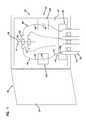
- FIG. 1is a schematic view showing an enclosure in accordance with the principles of the present disclosure for a fiber optic communication system.
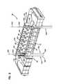
- FIG. 2is a front, top perspective view of a fiber optic cable anchoring arrangement in accordance with the principles of the present disclosure.
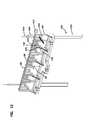
- FIG. 3is a back, top perspective view of the fiber optic cable anchoring assembly of FIG. 2 .
- FIG. 4is a front view of the fiber optic cable anchoring assembly of FIG. 2 .
- FIG. 5is a top view of the fiber optic cable anchoring assembly of FIG. 2 .
- FIG. 6is a side view of the fiber optic cable anchoring assembly of FIG. 2 .
- FIG. 7is a perspective view of a wedge suitable for use with the fiber optic cable anchoring assembly.
- FIG. 8is a side view of the wedge of FIG. 7 .
- FIG. 9is an end view of the wedge of FIG. 7 .
- FIG. 10is a fragmentary cross-sectional view of the wedge inserted into a channel of the fiber optic cable anchoring assembly.
- FIG. 11is a front, top perspective view of a portion of the fiber optic cable anchoring assembly of FIG. 2 .
- FIG. 12is a back, top perspective view of a portion of the fiber optic cable anchoring assembly of FIG. 2 .
- FIG. 1schematically depicts a piece of telecommunications equipment 18 including a fiber optic enclosure 20 (e.g., a cabinet).
- the fiber optic enclosure 20includes a main housing body 22 defining an interior region 23 , and an access door 24 for allowing the interior region 23 of the main housing body 22 to be readily accessed.
- the door 24is pivotably moveable between an open position where the interior region 23 of the main housing body 22 can be readily accessed, and a closed position where the interior region 23 of the main housing body 22 is sealed with respect to the outside environment.
- each of the fiber optic cables 30includes an outermost jacket 32 , at least one optical fiber 34 and a reinforcing structure 36 that runs the length of the fiber optic cable 30 and is positioned at least partially inside the outermost jacket 32 .
- each fiber optic cable 30is shown as having only one optical fiber 34 . It will be understood, however, that any of the fiber optic cables 30 could include multiple optical fibers.
- the outermost jacket 32surrounds and protects the optical fiber 34 .
- the outermost jackets 32 and the reinforcing structures 36are anchored to a cable anchoring assembly 38 secured (e.g., fastened, adhesively affixed, integrally molded, or otherwise affixed) to the fiber optic enclosure 20 .
- interior portions 40are shown as including only the optical fibers 34 .
- the optical fibers 34 of the interior portions 40can be enclosed within a protective structure such as a furcation tube or other type of tubing.
- the interior portions 40 of the fiber optic cables 30can be routed to various structures within the fiber optic enclosure 20 .
- the piece of telecommunications equipment 18is shown including splice regions 42 A, 42 B and a termination region 44 .
- These splice regions 42 A, 42 Bcan include a plurality of splice trays supporting a plurality of splice sleeves 46 protecting locations at which the interior portions 40 of the fiber optic cables 30 are spliced (i.e., fusion spliced) to other fibers.
- the interior portions 40are shown spliced to connectorized pigtails 48 each including a length of optical fiber 50 terminated by an optical connector 52 .
- the termination region 44 of the piece of telecommunications equipment 18can include a panel 56 to which a plurality of fiber optic adapters 58 are mounted.
- the fiber optic adapters 58are figured to mechanically interconnect two fiber optic connectors 52 in optical alignment with one another such that an optical transmission path is formed between the two fiber optic connectors 52 received within the fiber optic adapter 58 .
- the interior portions 40 of the fiber optic cables 30can be directly terminated with a fiber optic connector 52 without using an intermediate splice. It will be appreciated that selected ones of the connectors 52 can be interconnected by the fiber optic adapters 58 at the termination region 44 .
- the cable anchoring assembly 38includes a reinforcing structure anchoring block 60 mounted to a jacket anchoring block 62 .
- a reinforcing structure anchoring block 60mounted to a jacket anchoring block 62 .
- two different styles of fiber optic cable 30are shown anchored to the cable anchoring assembly 38 .
- fiber optic cables 30 Aare shown including optical fibers 34 A contained within a round jacket 32 A.
- Optional buffer tubes 33 Aare shown over portions of the optical fibers 34 A.
- the fiber optic cables 30 Aalso include reinforcing structures 36 A in the form of flexible strength members 36 A (e.g., aramid yarn) that run through the lengths of the fiber optic cables 30 A.
- the flexible strength members 36 Aprovide tensile reinforcement to the fiber optic cables 30 A, but do not provide meaningful resistance to buckling.
- the fiber optic cable 30 Bincludes an optical fiber 34 B contained within an outermost jacket 32 B having an elongated transverse cross-section. An optional buffer tube 33 B is shown over a portion of the optical fiber 34 B.
- the outermost jacket 32 Bincludes elongated, generally flat sides interconnected by rounded ends.
- the fiber optic cable 30 Balso includes reinforcing structures 36 B in the form of reinforcing rods (e.g., fiberglass reinforced epoxy) that are relatively stiff as compared to the flexible strength members 36 A. Such reinforcing rods are adapted to provide the fiber optic cable 30 B with tensile reinforcement and anti-buckling characteristics.
- the jacket anchoring block 62 of the cable anchoring assembly 38defines a plurality of jacket clamping locations 70 .
- Each jacket clamping location 70includes a channel 72 through which a portion of a cable with the jacket thereon can be routed.
- the clamping locations 70include ramp structures corresponding to each of the channels 72 .
- the clamping locations 70can include ramp surfaces 75 defined by slots 76 .
- the slots 76include ramp surfaces 75 that angle toward beds 71 of the channels 72 as the ramp surfaces 75 extend in a downward direction.
- the clamping locations 70work in concert with wedges 80 that are forced downwardly into the channels 72 to clamp the jackets 32 of the cables 30 within the channels 72 .
- the wedges 80include opposing flanges 81 , 82 that fit within the slots 76 .
- the flanges 81 , 82have angled end surfaces 83 that define angles that match the angles of the slots 76 .
- the wedges 80have clamping surfaces 84 that extend between the flanges 81 , 82 .
- the jacket of the fiber optic cableis clamped between the clamping surface 84 of the wedge 80 and the bed 71 of the channel 72 through the wedge action provided by the interaction of the angled surfaces of the wedge 80 and the angled surfaces of the channel 72 .
- the reinforcing structure anchoring block 60includes a first surface 90 and an oppositely disposed second surface 92 (shown in FIG. 3 ).
- the first surface 90is a front surface while the second surface 92 is a back surface.
- the reinforcing structure anchor block 60further includes a first end 94 , an oppositely disposed second end 96 and a first side 98 .
- the first and second ends 94 , 96extend between the first and second surfaces 90 , 92 while the first side 98 extends between the first and second ends 94 , 96 .
- the first side 98defines a plurality of notches 99 .
- the notches 99are generally V-shaped.
- the reinforcing structure anchor block 60further includes a plurality of reinforcing structure anchoring locations 100 that align generally with the jacket clamping locations 70 .
- the reinforcing structure anchoring locations 100are disposed on the first surface 90 .
- Each of the reinforcing structure anchoring locations 100defines a plurality of fastener openings 102 , each of which is configured to receive a fastener 103 .
- each of the reinforcing structure anchor locations 100defines two fastener openings 102 .
- the fasteners 103are threaded fasteners (e.g., screws, bolts or other threaded fasteners) that can be threaded into the fastener openings 102 .
- the reinforcing structure anchoring locations 100also include access slots 104 that provide radial access to the fastener openings 102 .
- Each of the access slots 104includes a first open end 106 and an oppositely dispose second open end 108 .
- the first open ends 106are positioned at the fastener openings 102 and provide a path between the access slots 104 and the fastener openings 102 .
- the access slots 104extend radially outwardly from center axes of the fastener openings 102 and have the second open ends 108 disposed at a periphery of the reinforcing structure anchor block 60 so that the second open ends 108 are offset from the fastener openings 102 .
- the second open ends 108are disposed at the first side 98 of the reinforcing structure anchor block 60 so that the second open ends 108 provide a path between the access slots 104 and the notches 99 in the first side 98 .
- the access slots 104have widths less than diameters of the fastener openings 102 .
- Each of the access slots 104provides an open lateral passage that allows the flexible reinforcing structure 36 A of the fiber optic cable 30 A to be inserted generally radially into the fastener opening 102 rather than requiring the reinforcing structure 36 A to be threaded axially through the fastener opening 102 .
- the term “generally radially”includes a pure radial direction as well as a direction merely having a radial spatial component relative to the central axis of the fastener opening 102 .
- the reinforcing structure anchoring locations 100are configured to accommodate different styles of reinforcing structures.
- each reinforcing structure anchoring location 100can be used to anchor flexible reinforcing structures 36 A or anti-buckling reinforcing structures 36 B.
- the anti-buckling reinforcing structures 36 Bare anchored to the reinforcing structure anchoring block 60 by passing the anti-buckling reinforcing structures 36 B between heads of the fasteners 103 and the first surface 90 of the reinforcing structure anchoring block 60 .
- the anti-buckling reinforcing structures 36 Bare clamped between the heads of the fasteners 103 and the first surface 90 of the reinforcing structure anchoring block 60 . In this way, the anti-buckling reinforcing structures 36 B are effectively secured, attached or otherwise anchored to the reinforcing structure anchoring block 60 .
- the reinforcing structure anchoring locations 100are also configured to readily accommodate the flexible reinforcing structures 36 A.
- the flexible reinforcing structure 36 Ais routed upwardly from the jacket clamping location 70 to the open upper end of the corresponding access slot 104 .
- the flexible reinforcing structure 36 Ais then moved downwardly in through the access slot 104 to the fastener opening 102 .
- the flexible reinforcing structure 36 AAs the flexible reinforcing structure 36 A is moved downwardly along the access slot 104 , the flexible reinforcing structure 36 A is bent at an angle (e.g., approximately a 90 degree angle) relative to an axis defined by the portion of the fiber optic cable 30 clamped at the jacket anchoring block 62 .
- the fastener 103can be threaded into the fastener opening 102 .
- the flexible reinforcing structure 36is effectively anchored within the fastener opening 102 .
- Anchoring of the flexible reinforcing structure 36 Acan be caused by clamping the flexible reinforcing structure 36 A between the threads of the fastener 103 and the wall defining the fastener opening 102 .
- Securement of the flexible reinforcing structure 36 A within the fastener opening 102can also be enhanced by wrapping of the flexible reinforcing structure 36 A about the fastener 103 as the fastener 103 is threaded into the fastener opening 102 .
- the configuration of the fastener opening 102 with the access slot 104allows the reinforcing structures 36 A to be quickly generally radially inserted into the fastener openings 102 without requiring the flexible reinforcing structures 36 A to be axially threaded through the fastener openings 102 .
- prewrapping of the reinforcing structure 36 A about the fasteners 103is not required since any wrapping necessary for securement of the reinforcing structures 36 A within the fastener openings 102 will occur automatically as the fasteners 103 are threaded within the fastener openings 102 .
- the threads of the fastener 103are able to retain the reinforcing structure 36 A within the fastener opening 102 without requiring the reinforcing structure 36 A to be wrapped about the fastener 103 .
- the flexible reinforcing structures 36 Aextend completely through the fastener openings 102 along axis of the fastener openings.
- the axis of the fastener openings 102are aligned at angles relative to the beds 71 of the channels 72 provided at the jacket clamping locations 70 .
- the portions of the cables clamped at the jacket clamping location 70are aligned at an angle relative to the portions of the reinforcing structures 36 A secured within the fastener openings 102 .
Landscapes
- Physics & Mathematics (AREA)
- General Physics & Mathematics (AREA)
- Optics & Photonics (AREA)
- Light Guides In General And Applications Therefor (AREA)
- Mechanical Coupling Of Light Guides (AREA)
- Piles And Underground Anchors (AREA)
Abstract
Description
Claims (20)
Priority Applications (1)
| Application Number | Priority Date | Filing Date | Title |
|---|---|---|---|
| US13/282,004US8620128B2 (en) | 2010-10-26 | 2011-10-26 | System and method for anchoring fiber optic cables to provide strain relief |
Applications Claiming Priority (2)
| Application Number | Priority Date | Filing Date | Title |
|---|---|---|---|
| US40683010P | 2010-10-26 | 2010-10-26 | |
| US13/282,004US8620128B2 (en) | 2010-10-26 | 2011-10-26 | System and method for anchoring fiber optic cables to provide strain relief |
Publications (2)
| Publication Number | Publication Date |
|---|---|
| US20120177334A1 US20120177334A1 (en) | 2012-07-12 |
| US8620128B2true US8620128B2 (en) | 2013-12-31 |
Family
ID=45994710
Family Applications (1)
| Application Number | Title | Priority Date | Filing Date |
|---|---|---|---|
| US13/282,004Active2031-11-24US8620128B2 (en) | 2010-10-26 | 2011-10-26 | System and method for anchoring fiber optic cables to provide strain relief |
Country Status (4)
| Country | Link |
|---|---|
| US (1) | US8620128B2 (en) |
| EP (1) | EP2633356A4 (en) |
| RU (1) | RU2579819C2 (en) |
| WO (1) | WO2012058275A2 (en) |
Cited By (6)
| Publication number | Priority date | Publication date | Assignee | Title |
|---|---|---|---|---|
| US20140270677A1 (en)* | 2013-03-13 | 2014-09-18 | Adc Telecommunications, Inc. | Anchoring cables to rack with self-locking cable clamp arrangements |
| US9971120B2 (en) | 2012-10-31 | 2018-05-15 | Commscope Technologies Llc | Anchoring cables to rack with cable clamp arrangements |
| US11194112B2 (en)* | 2015-12-31 | 2021-12-07 | CommScope Connectivity Belgium BVBA | Cable fixation devices and methods |
| US11287595B2 (en)* | 2018-12-04 | 2022-03-29 | Hubbell Incorporated | Fiber optic dead-end cable clamp with central actuator |
| US11314030B2 (en)* | 2017-10-09 | 2022-04-26 | CommScope Connectivity Belgium BVBA | Cable fixation devices and methods |
| US11452223B2 (en)* | 2017-11-22 | 2022-09-20 | Telefonaktiebolaget Lm Ericsson (Publ) | Cable sealing assembly |
Families Citing this family (8)
| Publication number | Priority date | Publication date | Assignee | Title |
|---|---|---|---|---|
| EP3039760A2 (en)* | 2013-08-30 | 2016-07-06 | Tyco Electronics Raychem BVBA | Cable fixation device and method |
| WO2018154125A1 (en) | 2017-02-27 | 2018-08-30 | CommScope Connectivity Belgium BVBA | Fiber optic cable fixation device and fiber optic cable mounting system comprising same |
| PT110213B (en)* | 2017-07-21 | 2020-09-29 | C3T Technologies, Sa | MULTI-LEVEL OPTICAL POINT FOR MOORING, CONNECTION, ACCOMMODATION AND DERIVATION OF EXTERNAL FIBER OPTIC CABLES ON A SUPPORT |
| FR3078411B1 (en)* | 2018-02-28 | 2020-02-07 | Telenco Networks | TIGHTENING MEMBER FOR OPTICAL FIBER CABLE |
| US11287596B2 (en) | 2018-06-15 | 2022-03-29 | Commscope Technologies Llc | Methods, kits, and systems incorporating a self-amalgamating tape for clamping fiber optic cable |
| CN109613669B (en)* | 2018-12-07 | 2020-10-16 | 东莞理工学院 | A distributed optical fiber reinforcement device embedded in a structure and a method of using the same |
| US11867962B2 (en) | 2019-09-16 | 2024-01-09 | Commscope Technologies Llc | Cable fixation assembly with strength member anchor adapter |
| WO2023076734A1 (en)* | 2021-11-01 | 2023-05-04 | Commscope Technologies Llc | Fiber optic enclosure with fiber tubes sealed outside the enclosure |
Citations (18)
| Publication number | Priority date | Publication date | Assignee | Title |
|---|---|---|---|---|
| US3614298A (en)* | 1970-02-19 | 1971-10-19 | John T Thompson | Cable splice casing with conductive anchorage to cable sheath and shield |
| US3798349A (en)* | 1970-02-19 | 1974-03-19 | G Gillemot | Molded plastic splice casing with combination cable anchorage and cable shielding grounding facility |
| US4795230A (en)* | 1986-04-17 | 1989-01-03 | Sat (Societe Anonyme De Telecommunications | Device and process for spreading optical fibers emerging from a cable to be connected |
| US5030136A (en) | 1989-04-14 | 1991-07-09 | Minnesota Mining And Manufacturing Company | Connector for cables |
| US5397859A (en) | 1993-12-10 | 1995-03-14 | The Whitaker Corporation | Enclosure with sealant for spliced coaxial cables |
| US20040086254A1 (en) | 2001-03-14 | 2004-05-06 | Kristof Vastmans | Cable termination device |
| US6983095B2 (en) | 2003-11-17 | 2006-01-03 | Fiber Optic Network Solutions Corporation | Systems and methods for managing optical fibers and components within an enclosure in an optical communications network |
| JP2007114437A (en) | 2005-10-19 | 2007-05-10 | Hochiki Corp | Communication cable fixing structure |
| US7369741B2 (en) | 2003-11-17 | 2008-05-06 | Fiber Optics Network Solutions Corp. | Storage adapter with dust cap posts |
| US20080285933A1 (en) | 2007-05-15 | 2008-11-20 | Commscope, Inc. | Fiber optic splice and distribution enclosure |
| US7603018B2 (en) | 2007-01-16 | 2009-10-13 | Tyco Electronics Corporation | Cable enclosure assemblies and methods for using the same |
| US20100092147A1 (en) | 2006-10-16 | 2010-04-15 | Christophe Desard | Optical fiber cable retention device |
| US7720343B2 (en) | 2006-02-13 | 2010-05-18 | Adc Telecommunications, Inc. | Fiber distribution hub with swing frame and modular termination panels |
| US7758256B2 (en)* | 2008-09-29 | 2010-07-20 | Tyco Electronics Corporation | Connector for tight-jacketed optical fiber cable |
| US20110026894A1 (en) | 2009-07-01 | 2011-02-03 | Paula Rudenick | Wall-mounted fiber distribution hub |
| US7925135B2 (en)* | 2008-09-03 | 2011-04-12 | Tyco Electronics Corporation | Cable clamping devices and methods for using the same |
| US7970249B2 (en) | 2008-02-15 | 2011-06-28 | Adc Telecommunications, Inc. | Fiber optic splice enclosure |
| US8032001B2 (en)* | 2008-09-03 | 2011-10-04 | Tyco Electronics Corporation | Cable strain relief clamping devices and methods for using the same |
Family Cites Families (3)
| Publication number | Priority date | Publication date | Assignee | Title |
|---|---|---|---|---|
| DE3833714A1 (en) | 1987-12-23 | 1989-07-13 | Gte Prod Corp | DEVICE FOR HOLDING OPTICAL FIBER CABLES |
| JP2000206358A (en) | 1999-01-11 | 2000-07-28 | Nec Corp | Tension member holding device |
| CA2558996A1 (en)* | 2004-03-08 | 2005-09-22 | Adc Telecommunications, Inc. | Fiber access terminal |
- 2011
- 2011-10-26USUS13/282,004patent/US8620128B2/enactiveActive
- 2011-10-26WOPCT/US2011/057827patent/WO2012058275A2/enactiveApplication Filing
- 2011-10-26EPEP11836989.1Apatent/EP2633356A4/ennot_activeWithdrawn
- 2011-10-26RURU2013124025/28Apatent/RU2579819C2/ennot_activeIP Right Cessation
Patent Citations (18)
| Publication number | Priority date | Publication date | Assignee | Title |
|---|---|---|---|---|
| US3614298A (en)* | 1970-02-19 | 1971-10-19 | John T Thompson | Cable splice casing with conductive anchorage to cable sheath and shield |
| US3798349A (en)* | 1970-02-19 | 1974-03-19 | G Gillemot | Molded plastic splice casing with combination cable anchorage and cable shielding grounding facility |
| US4795230A (en)* | 1986-04-17 | 1989-01-03 | Sat (Societe Anonyme De Telecommunications | Device and process for spreading optical fibers emerging from a cable to be connected |
| US5030136A (en) | 1989-04-14 | 1991-07-09 | Minnesota Mining And Manufacturing Company | Connector for cables |
| US5397859A (en) | 1993-12-10 | 1995-03-14 | The Whitaker Corporation | Enclosure with sealant for spliced coaxial cables |
| US20040086254A1 (en) | 2001-03-14 | 2004-05-06 | Kristof Vastmans | Cable termination device |
| US7369741B2 (en) | 2003-11-17 | 2008-05-06 | Fiber Optics Network Solutions Corp. | Storage adapter with dust cap posts |
| US6983095B2 (en) | 2003-11-17 | 2006-01-03 | Fiber Optic Network Solutions Corporation | Systems and methods for managing optical fibers and components within an enclosure in an optical communications network |
| JP2007114437A (en) | 2005-10-19 | 2007-05-10 | Hochiki Corp | Communication cable fixing structure |
| US7720343B2 (en) | 2006-02-13 | 2010-05-18 | Adc Telecommunications, Inc. | Fiber distribution hub with swing frame and modular termination panels |
| US20100092147A1 (en) | 2006-10-16 | 2010-04-15 | Christophe Desard | Optical fiber cable retention device |
| US7603018B2 (en) | 2007-01-16 | 2009-10-13 | Tyco Electronics Corporation | Cable enclosure assemblies and methods for using the same |
| US20080285933A1 (en) | 2007-05-15 | 2008-11-20 | Commscope, Inc. | Fiber optic splice and distribution enclosure |
| US7970249B2 (en) | 2008-02-15 | 2011-06-28 | Adc Telecommunications, Inc. | Fiber optic splice enclosure |
| US7925135B2 (en)* | 2008-09-03 | 2011-04-12 | Tyco Electronics Corporation | Cable clamping devices and methods for using the same |
| US8032001B2 (en)* | 2008-09-03 | 2011-10-04 | Tyco Electronics Corporation | Cable strain relief clamping devices and methods for using the same |
| US7758256B2 (en)* | 2008-09-29 | 2010-07-20 | Tyco Electronics Corporation | Connector for tight-jacketed optical fiber cable |
| US20110026894A1 (en) | 2009-07-01 | 2011-02-03 | Paula Rudenick | Wall-mounted fiber distribution hub |
Non-Patent Citations (1)
| Title |
|---|
| International Search Report and Written Opinion mailed May 22, 2012. |
Cited By (12)
| Publication number | Priority date | Publication date | Assignee | Title |
|---|---|---|---|---|
| US9971120B2 (en) | 2012-10-31 | 2018-05-15 | Commscope Technologies Llc | Anchoring cables to rack with cable clamp arrangements |
| US20140270677A1 (en)* | 2013-03-13 | 2014-09-18 | Adc Telecommunications, Inc. | Anchoring cables to rack with self-locking cable clamp arrangements |
| US9291791B2 (en)* | 2013-03-13 | 2016-03-22 | Commscope Technologies Llc | Anchoring cables to rack with self-locking cable clamp arrangements |
| US9939601B2 (en) | 2013-03-13 | 2018-04-10 | Commscope Technologies Llc | Anchoring cables to rack with self-locking cable clamp arrangements |
| US11194112B2 (en)* | 2015-12-31 | 2021-12-07 | CommScope Connectivity Belgium BVBA | Cable fixation devices and methods |
| US11314030B2 (en)* | 2017-10-09 | 2022-04-26 | CommScope Connectivity Belgium BVBA | Cable fixation devices and methods |
| US11452223B2 (en)* | 2017-11-22 | 2022-09-20 | Telefonaktiebolaget Lm Ericsson (Publ) | Cable sealing assembly |
| US20220322556A1 (en)* | 2017-11-22 | 2022-10-06 | Telefonaktiebolaget Lm Ericsson (Publ) | Cable sealing assembly |
| US11665842B2 (en)* | 2017-11-22 | 2023-05-30 | Telefonaktiebolaget Lm Ericsson (Publ) | Cable sealing assembly |
| US12035496B2 (en)* | 2017-11-22 | 2024-07-09 | Telefonaktiebolaget Lm Ericsson (Publ) | Cable sealing assembly |
| US11287595B2 (en)* | 2018-12-04 | 2022-03-29 | Hubbell Incorporated | Fiber optic dead-end cable clamp with central actuator |
| US20220413246A1 (en)* | 2018-12-04 | 2022-12-29 | Hubbell Incorporated | Fiber optic dead-end cable clamp |
Also Published As
| Publication number | Publication date |
|---|---|
| EP2633356A4 (en) | 2014-04-09 |
| WO2012058275A3 (en) | 2012-07-26 |
| US20120177334A1 (en) | 2012-07-12 |
| RU2013124025A (en) | 2014-12-10 |
| EP2633356A2 (en) | 2013-09-04 |
| WO2012058275A2 (en) | 2012-05-03 |
| RU2579819C2 (en) | 2016-04-10 |
Similar Documents
| Publication | Publication Date | Title |
|---|---|---|
| US8620128B2 (en) | System and method for anchoring fiber optic cables to provide strain relief | |
| US11506856B2 (en) | Pass-through assembly having an anchor member and a cover | |
| US12066676B2 (en) | Fiber optic cable with flexible conduit | |
| US8903216B2 (en) | Cable strain relief clamping devices and methods for using the same | |
| US20190204523A1 (en) | Optical termination enclosure | |
| EP0817985B1 (en) | Fiber optic splice organizers | |
| US8577199B2 (en) | Hauling shroud for hauling fibre optic cable along a conduit | |
| US20170329096A1 (en) | Two-sided optical fiber management tray and method of use | |
| EP3612881B1 (en) | Fiber routing systems | |
| US20110280525A1 (en) | Splice Enclosure Arrangement for Fiber Optic Cables | |
| US8649649B2 (en) | Fiber distribution hub with connectorized stub cables | |
| EP3032304B1 (en) | Pre-cabled telecommunications assembly | |
| US11867962B2 (en) | Cable fixation assembly with strength member anchor adapter | |
| CA3067820A1 (en) | Cable support devices for fiber optic communications networks |
Legal Events
| Date | Code | Title | Description |
|---|---|---|---|
| AS | Assignment | Owner name:ADC TELECOMMUNICATIONS, INC., MINNESOTA Free format text:ASSIGNMENT OF ASSIGNORS INTEREST;ASSIGNORS:HOLMBERG, MATTHEW;RUDENICK, PAULA;REEL/FRAME:028276/0325 Effective date:20120313 | |
| STCF | Information on status: patent grant | Free format text:PATENTED CASE | |
| AS | Assignment | Owner name:TYCO ELECTRONICS SERVICES GMBH, SWITZERLAND Free format text:ASSIGNMENT OF ASSIGNORS INTEREST;ASSIGNORS:ADC TELECOMMUNICATIONS, INC.;TE CONNECTIVITY SOLUTIONS GMBH;REEL/FRAME:036908/0443 Effective date:20150825 | |
| AS | Assignment | Owner name:COMMSCOPE EMEA LIMITED, IRELAND Free format text:ASSIGNMENT OF ASSIGNORS INTEREST;ASSIGNOR:TYCO ELECTRONICS SERVICES GMBH;REEL/FRAME:036956/0001 Effective date:20150828 | |
| AS | Assignment | Owner name:COMMSCOPE TECHNOLOGIES LLC, NORTH CAROLINA Free format text:ASSIGNMENT OF ASSIGNORS INTEREST;ASSIGNOR:COMMSCOPE EMEA LIMITED;REEL/FRAME:037012/0001 Effective date:20150828 | |
| AS | Assignment | Owner name:JPMORGAN CHASE BANK, N.A., AS COLLATERAL AGENT, ILLINOIS Free format text:PATENT SECURITY AGREEMENT (TERM);ASSIGNOR:COMMSCOPE TECHNOLOGIES LLC;REEL/FRAME:037513/0709 Effective date:20151220 Owner name:JPMORGAN CHASE BANK, N.A., AS COLLATERAL AGENT, ILLINOIS Free format text:PATENT SECURITY AGREEMENT (ABL);ASSIGNOR:COMMSCOPE TECHNOLOGIES LLC;REEL/FRAME:037514/0196 Effective date:20151220 Owner name:JPMORGAN CHASE BANK, N.A., AS COLLATERAL AGENT, IL Free format text:PATENT SECURITY AGREEMENT (ABL);ASSIGNOR:COMMSCOPE TECHNOLOGIES LLC;REEL/FRAME:037514/0196 Effective date:20151220 Owner name:JPMORGAN CHASE BANK, N.A., AS COLLATERAL AGENT, IL Free format text:PATENT SECURITY AGREEMENT (TERM);ASSIGNOR:COMMSCOPE TECHNOLOGIES LLC;REEL/FRAME:037513/0709 Effective date:20151220 | |
| FPAY | Fee payment | Year of fee payment:4 | |
| AS | Assignment | Owner name:REDWOOD SYSTEMS, INC., NORTH CAROLINA Free format text:RELEASE BY SECURED PARTY;ASSIGNOR:JPMORGAN CHASE BANK, N.A.;REEL/FRAME:048840/0001 Effective date:20190404 Owner name:ALLEN TELECOM LLC, ILLINOIS Free format text:RELEASE BY SECURED PARTY;ASSIGNOR:JPMORGAN CHASE BANK, N.A.;REEL/FRAME:048840/0001 Effective date:20190404 Owner name:COMMSCOPE, INC. OF NORTH CAROLINA, NORTH CAROLINA Free format text:RELEASE BY SECURED PARTY;ASSIGNOR:JPMORGAN CHASE BANK, N.A.;REEL/FRAME:048840/0001 Effective date:20190404 Owner name:ANDREW LLC, NORTH CAROLINA Free format text:RELEASE BY SECURED PARTY;ASSIGNOR:JPMORGAN CHASE BANK, N.A.;REEL/FRAME:048840/0001 Effective date:20190404 Owner name:COMMSCOPE TECHNOLOGIES LLC, NORTH CAROLINA Free format text:RELEASE BY SECURED PARTY;ASSIGNOR:JPMORGAN CHASE BANK, N.A.;REEL/FRAME:048840/0001 Effective date:20190404 Owner name:ANDREW LLC, NORTH CAROLINA Free format text:RELEASE BY SECURED PARTY;ASSIGNOR:JPMORGAN CHASE BANK, N.A.;REEL/FRAME:049260/0001 Effective date:20190404 Owner name:ALLEN TELECOM LLC, ILLINOIS Free format text:RELEASE BY SECURED PARTY;ASSIGNOR:JPMORGAN CHASE BANK, N.A.;REEL/FRAME:049260/0001 Effective date:20190404 Owner name:COMMSCOPE TECHNOLOGIES LLC, NORTH CAROLINA Free format text:RELEASE BY SECURED PARTY;ASSIGNOR:JPMORGAN CHASE BANK, N.A.;REEL/FRAME:049260/0001 Effective date:20190404 Owner name:REDWOOD SYSTEMS, INC., NORTH CAROLINA Free format text:RELEASE BY SECURED PARTY;ASSIGNOR:JPMORGAN CHASE BANK, N.A.;REEL/FRAME:049260/0001 Effective date:20190404 Owner name:COMMSCOPE, INC. OF NORTH CAROLINA, NORTH CAROLINA Free format text:RELEASE BY SECURED PARTY;ASSIGNOR:JPMORGAN CHASE BANK, N.A.;REEL/FRAME:049260/0001 Effective date:20190404 | |
| AS | Assignment | Owner name:JPMORGAN CHASE BANK, N.A., NEW YORK Free format text:ABL SECURITY AGREEMENT;ASSIGNORS:COMMSCOPE, INC. OF NORTH CAROLINA;COMMSCOPE TECHNOLOGIES LLC;ARRIS ENTERPRISES LLC;AND OTHERS;REEL/FRAME:049892/0396 Effective date:20190404 Owner name:JPMORGAN CHASE BANK, N.A., NEW YORK Free format text:TERM LOAN SECURITY AGREEMENT;ASSIGNORS:COMMSCOPE, INC. OF NORTH CAROLINA;COMMSCOPE TECHNOLOGIES LLC;ARRIS ENTERPRISES LLC;AND OTHERS;REEL/FRAME:049905/0504 Effective date:20190404 Owner name:WILMINGTON TRUST, NATIONAL ASSOCIATION, AS COLLATE Free format text:PATENT SECURITY AGREEMENT;ASSIGNOR:COMMSCOPE TECHNOLOGIES LLC;REEL/FRAME:049892/0051 Effective date:20190404 Owner name:WILMINGTON TRUST, NATIONAL ASSOCIATION, AS COLLATERAL AGENT, CONNECTICUT Free format text:PATENT SECURITY AGREEMENT;ASSIGNOR:COMMSCOPE TECHNOLOGIES LLC;REEL/FRAME:049892/0051 Effective date:20190404 | |
| MAFP | Maintenance fee payment | Free format text:PAYMENT OF MAINTENANCE FEE, 8TH YEAR, LARGE ENTITY (ORIGINAL EVENT CODE: M1552); ENTITY STATUS OF PATENT OWNER: LARGE ENTITY Year of fee payment:8 | |
| AS | Assignment | Owner name:WILMINGTON TRUST, DELAWARE Free format text:SECURITY INTEREST;ASSIGNORS:ARRIS SOLUTIONS, INC.;ARRIS ENTERPRISES LLC;COMMSCOPE TECHNOLOGIES LLC;AND OTHERS;REEL/FRAME:060752/0001 Effective date:20211115 | |
| AS | Assignment | Owner name:APOLLO ADMINISTRATIVE AGENCY LLC, NEW YORK Free format text:SECURITY INTEREST;ASSIGNORS:ARRIS ENTERPRISES LLC;COMMSCOPE TECHNOLOGIES LLC;COMMSCOPE INC., OF NORTH CAROLINA;AND OTHERS;REEL/FRAME:069889/0114 Effective date:20241217 | |
| AS | Assignment | Owner name:RUCKUS WIRELESS, LLC (F/K/A RUCKUS WIRELESS, INC.), NORTH CAROLINA Free format text:RELEASE OF SECURITY INTEREST AT REEL/FRAME 049905/0504;ASSIGNOR:JPMORGAN CHASE BANK, N.A., AS COLLATERAL AGENT;REEL/FRAME:071477/0255 Effective date:20241217 Owner name:COMMSCOPE TECHNOLOGIES LLC, NORTH CAROLINA Free format text:RELEASE OF SECURITY INTEREST AT REEL/FRAME 049905/0504;ASSIGNOR:JPMORGAN CHASE BANK, N.A., AS COLLATERAL AGENT;REEL/FRAME:071477/0255 Effective date:20241217 Owner name:COMMSCOPE, INC. OF NORTH CAROLINA, NORTH CAROLINA Free format text:RELEASE OF SECURITY INTEREST AT REEL/FRAME 049905/0504;ASSIGNOR:JPMORGAN CHASE BANK, N.A., AS COLLATERAL AGENT;REEL/FRAME:071477/0255 Effective date:20241217 Owner name:ARRIS SOLUTIONS, INC., NORTH CAROLINA Free format text:RELEASE OF SECURITY INTEREST AT REEL/FRAME 049905/0504;ASSIGNOR:JPMORGAN CHASE BANK, N.A., AS COLLATERAL AGENT;REEL/FRAME:071477/0255 Effective date:20241217 Owner name:ARRIS TECHNOLOGY, INC., NORTH CAROLINA Free format text:RELEASE OF SECURITY INTEREST AT REEL/FRAME 049905/0504;ASSIGNOR:JPMORGAN CHASE BANK, N.A., AS COLLATERAL AGENT;REEL/FRAME:071477/0255 Effective date:20241217 Owner name:ARRIS ENTERPRISES LLC (F/K/A ARRIS ENTERPRISES, INC.), NORTH CAROLINA Free format text:RELEASE OF SECURITY INTEREST AT REEL/FRAME 049905/0504;ASSIGNOR:JPMORGAN CHASE BANK, N.A., AS COLLATERAL AGENT;REEL/FRAME:071477/0255 Effective date:20241217 | |
| FEPP | Fee payment procedure | Free format text:MAINTENANCE FEE REMINDER MAILED (ORIGINAL EVENT CODE: REM.); ENTITY STATUS OF PATENT OWNER: LARGE ENTITY |