US8619529B1 - Methods and devices for enhanced adaptive margining based on channel threshold measure - Google Patents
Methods and devices for enhanced adaptive margining based on channel threshold measureDownload PDFInfo
- Publication number
- US8619529B1 US8619529B1US13/427,559US201213427559AUS8619529B1US 8619529 B1US8619529 B1US 8619529B1US 201213427559 AUS201213427559 AUS 201213427559AUS 8619529 B1US8619529 B1US 8619529B1
- Authority
- US
- United States
- Prior art keywords
- margining
- detected
- media defect
- defect
- amount
- Prior art date
- Legal status (The legal status is an assumption and is not a legal conclusion. Google has not performed a legal analysis and makes no representation as to the accuracy of the status listed.)
- Expired - Fee Related
Links
- 238000000034methodMethods0.000titleclaimsdescription32
- 230000003044adaptive effectEffects0.000title1
- 230000007547defectEffects0.000claimsabstractdescription255
- 238000012360testing methodMethods0.000claimsabstractdescription13
- 238000001514detection methodMethods0.000claimsdescription12
- 230000007423decreaseEffects0.000description5
- 238000012512characterization methodMethods0.000description4
- 239000000696magnetic materialSubstances0.000description3
- 238000004519manufacturing processMethods0.000description3
- 230000007704transitionEffects0.000description3
- 230000003247decreasing effectEffects0.000description2
- 239000000356contaminantSubstances0.000description1
- 235000000396ironNutrition0.000description1
- 230000007257malfunctionEffects0.000description1
- 238000012986modificationMethods0.000description1
- 230000004048modificationEffects0.000description1
- 239000002245particleSubstances0.000description1
- 230000002085persistent effectEffects0.000description1
- 238000011084recoveryMethods0.000description1
- 230000035945sensitivityEffects0.000description1
- 229910001220stainless steelInorganic materials0.000description1
- 239000010935stainless steelSubstances0.000description1
- 238000006467substitution reactionMethods0.000description1
- 230000001052transient effectEffects0.000description1
Images


Classifications
- G—PHYSICS
- G11—INFORMATION STORAGE
- G11B—INFORMATION STORAGE BASED ON RELATIVE MOVEMENT BETWEEN RECORD CARRIER AND TRANSDUCER
- G11B20/00—Signal processing not specific to the method of recording or reproducing; Circuits therefor
- G11B20/10—Digital recording or reproducing
- G11B20/18—Error detection or correction; Testing, e.g. of drop-outs
Definitions
- defects on the media surfacecan cause the read channel to repeatedly detect incorrect data (hard errors). Very large defects may result in hard errors that are too long for the disk drive ECC algorithm to detect.
- Defect scansare used in the manufacturing process to flag those sectors with large defects so they are excluded from use during normal drive operation. The defect scan involves two main steps:
- a high frequency patternis written to maximize the probability of is actually writing a transition on a small defect.
- the highest frequency pattern a read channel can usually writeis a 2T preamble (transitions are spaced 2 ⁇ T TBG apart). If a transition is written on a defect, the resulting magnetic head amplitude increases or decreases based on the type of defect. A decrease in magnetic material on the media correspondingly decreases the amplitude of the read back signal (resulting in a localized read back signal drop-out) and an increase in magnetic material on the media correspondingly increases the amplitude of the read back signal (resulting in a localized read back signal drop-in).
- the disk drivemay fail the manufacturing process when too many defects are detected.
- a predetermined space around the detected defectis designated as a margin that becomes unavailable for user data.
- Such defectsare commonly known as “grown defects” and often manifest themselves outside of the predetermined margins designated around the detected media defect.
- the disk drivemay ultimately fail in the hands of the end user, due to such grown defects.
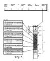
- FIG. 1shows major components of a disk drive, according to one embodiment.
- FIG. 2shows a read-back signal and a method of estimating a depth of a detected media defect, according to one embodiment.
- FIG. 3shows the characterization of a detected shallow media defect, according to one embodiment.
- FIG. 4shows the characterization of a detected deep media defect, according to one embodiment.
- FIG. 5shows aspects of a method for estimating the depth of a detected media defect and the location of the greatest local depth, according to one embodiment.
- FIG. 6shows an example of a determination of a margining amount for a detected media defect, according to one embodiment.
- FIG. 7shows another example of a determination of a margining amount for a detected media defect, according to one embodiment.
- FIG. 8is a flowchart of a method to enable defect margining during testing of a disk drive, according to one embodiment.
- FIG. 1shows the principal components of an exemplary magnetic disk drive 100 constructed in accordance with one embodiment.
- the disk drive 100comprises a head disk assembly (HDA) 144 and a printed circuit board assembly (PCBA) 141 .
- the HDA 144includes a base 161 and a cover 171 attached to the base 161 that collectively house a disk 102 or a stack of two or more such disks 102 configured for improved margining of detected media defects, according to one embodiment.
- the HDA 144also includes a spindle motor 113 attached to the base 161 for rotating the disk 102 , an HSA 150 , and a pivot bearing cartridge 184 (such as a stainless steel pivot bearing cartridge, for example) that rotatably supports the head stack assembly (HSA) 150 on the base 161 .
- the spindle motor 113rotates the disk 102 at a constant angular velocity.
- the HSA 150comprises a swing-type or rotary actuator assembly 152 , at least one head gimbal assembly (HGA) 110 coupled to the load beam 303 that includes a flexure constructed as described above, and a flex circuit cable assembly.
- HGAhead gimbal assembly
- the rotary actuator assembly 152includes a body portion, at least one actuator arm cantilevered from the body portion, and a coil portion 156 cantilevered from the body portion in an opposite direction from the actuator arm.
- the actuator armsupports the HGA 110 that, in turn, includes and supports the slider(s).
- the flex circuit cable assemblymay include the flexible cable 180 and a flex clamp 159 .
- the flexible cable 180 and the flexure of the HGA 110are structured and coupled in the manner described above.
- the HSA 150is pivotally secured to the base 161 via the pivot-bearing cartridge 184 so that the slider at the distal end of the HGA 110 may be moved over the surfaces of the disk(s) 102 .
- the pivot-bearing cartridge 184enables the HSA 150 to pivot about a pivot axis.
- the storage capacity of the HDA 144may be increased by, for example, increasing the track density (the TPI) on the disk 102 and/or by including additional disks 102 in a disk stack and by an HSA 150 having a vertical stack of HGAs 110 supported by a rotary actuator assembly 152 having multiple actuator arms.
- the “rotary” or “swing-type” actuator assembly 152rotates on the pivot bearing 184 cartridge about its pivot axis between limited positions and further includes a coil portion 156 that extends from one side of the body portion to interact with one or more permanent magnets 190 mounted to back irons 170 , 172 to form a voice coil motor (VCM).
- VCMvoice coil motor
- the VCMcauses the HSA 150 to pivot about the actuator pivot axis to cause the slider and the read-write transducers thereof to sweep radially over the disk(s) 102 .
- the PCBA 141includes a processor 142 and control circuitry configured to read data from and write data to the disk(s) 102 and to carry out the methods and margining functionality described and shown herein.
- One embodimentis a disk drive, such as shown in FIG. 1 , configured to enable media defect margining.
- the diskmay comprise a disk 102 comprising a plurality of tracks and a head actuated over the disk 102 .
- a processorsuch as shown at 142 , may be configured to determine the amount of margining to apply to a detected media defect by testing the media of the disk drive to detect one or more such media defects.
- the processor 142may be configured to carry out the method of enabling defect margining during testing of a disk drive, as shown in FIG. 8 .
- the detected defectmay be a micro defect, a large defect, a shallow defect or a thermal asperity (TA), for example.
- TAsare tribological events characterized by a transient read signal spike that may cause giant magnetoresistance (GMR) and MR heads of disk drives to temporarily malfunction, resulting in a temporary disruption in the recovery of data. Indeed, TAs may be caused by sensor temperature rise due to frictional contact with disk asperities or contaminant particles.
- the depth of the detected media defectmay be estimated, and the margining amount may be determined, based at least on the estimated depth of the is detected media defect.
- the margining amountmay comprise a number of contiguous cylinders to add as a margin to the inner diameter (ID) and/or outer diameter (OD) ends of the detected media defect that will be unavailable for storing user data.
- the processor 142may be configured to apply the determined margining amount to the detected media defect.
- the depth of the detected media defectmay be determined using a drop-out register, as shown in FIG. 2 .
- FIG. 2shows a read-back signal and a method of estimating a depth of a detected media defect, according to one embodiment.
- the amplitude of the read-back signal 202locally decreases at 214 , which may be indicative of a localized decrease in magnetic material on the media, most likely due to a defect (e.g., a scratch) in one or more of the magnetic layers on the disk 102 .
- the drop-out registermay be a seven bit register, meaning that a Digital-to-Analog (DAC) count that may be programmed into this register may range from 0 to a count of 127, corresponding to a granularity of 127 different detectable amplitudes for the read-back signal 202 .
- DACDigital-to-Analog
- detection sensitivitymay be correspondingly reduced.
- the amplitude of the read-back signal at the detected defectmay be characterized, 1/127 th increments of the nominal value of the read-back signal, in the case of a 7-bit drop-out register.
- no read back signal 202is detected at the nominal threshold 204 .
- the DAC count of the drop-out registermay then be iteratively decreased to a next lowest threshold, as shown at 206 .
- the detection thresholdmay then be lowered again. As shown, the read-back signal 202 is still undetectable at the detection threshold 208 .
- the DAC count of the drop-out is registeris reduced, thereby lowering the detection threshold to 210 that the read-back signal 202 is detected.
- the depth of the detected media defectis generally proportional to the magnitude of the read-back signal 202
- a quantitative measure of the depth of the detected media defectmay be characterized (as a percentage of nominal, for example) and/or numerically estimated as the DAC count where detection of the read-back signal 202 was re-established at a given detection threshold.
- FIG. 3shows the characterization of a shallow detected media defect, according to one embodiment.
- the read-back signal 310shows a drop-out at 302 , 306 indicative of a defect in the media under the read head.
- the nominal thresholdas indicated by the drop-out register, is 0x3Ah.
- a signal on a Non-Return-To-Zero (NRZ) busmay be asserted as shown at 304 when the magnitude of the read-back signal 310 drops below the nominal threshold.
- NRZNon-Return-To-Zero
- the defectappears to be barely detectable when the threshold (and hence the DAC count of the drop-out register) is reduced to 0x34h and is undetectable when the detection threshold is reduced to 0x33h. Therefore, the defect in the media evidenced by the read-back signal 310 at 302 , 306 may be characterized as having a relatively shallow depth of about 10% ((1-52 d /58 d ) ⁇ 100) of the maximum DAC count.
- FIG. 4shows the characterization of a detected deep media defect, according to one embodiment.
- the read-back signal 410shows a drop-out at 402 , 406 indicative of a defect in the media under the read head.
- the nominal thresholdas indicated by the drop-out register, is also 0x3Ah.
- a signal on the NRZ busis asserted at 404 at nominal threshold 0x03Ah, indicative of a drop-out of the read-back signal under the read head.
- the defect in the media evidenced by the read-back signal 410 at the location indicated at 402 , 406may be characterized as having a depth of 100% of the maximum DAC count.
- the margining to be applied to a detected media defectmay be based upon the estimated depth of the detected media defect. Deeper defects may be allocated a greater margining amount (e.g., a greater number of tracks or cylinders) than comparatively shallower detected media defects, for example. According to one embodiment, the amount of margining to apply to a detected media defect may be based not only on the estimated depth of the media defect, but may also be based on the length of the detected media defect. According to one embodiment, the amount of margining to apply to a detected media defect may be based not only on the estimated depth of the media defect and the length of the detected media defect, but also on the presence of a TA.
- an amount of margining to apply to a detected media defectmay, according to one embodiment, be based on a formula that utilizes a margining length amount based on the length of the detected media defect, an extra depth margining amount based upon the estimated depth of the detected media defect and an extra TA margining amount based on the presence of a TA on the media in the vicinity of the detected media defect.
- the margining length amountmay be calculated as [length of detected media defect/2]+1.
- the length of the detected media defectmay be calculated by subtracting the highest track number in which the media defect is present from the lowest track number in which the same media defect is present.
- the extra depth margining amountmay be quantified by a ratio interrelating the estimated depth and the margining length amount.
- the extra depth margining amountas [(estimated depth of media defect ⁇ margining length amount)/(estimated depth of media defect+margining length amount)].
- the portion of the amount of margining to apply to a detected media defect attributable to a detected thermal asperitymay be related to the margining length amount.
- the extra TA margining amountmay be a product of a scaling factor and the margining length amount.
- the scaling factormay be selected, for example, to be is less than unity.
- the scaling factormay be selected to be less than 0.5.
- the scaling factormay be selected to be less than 0.3.
- the scaling factormay be selected to be 0.15.
- the margining amount to be applied to the detected media defectmay be calculated as the sum of the extra depth margining amount and the extra TA margining amount. Applying a customized margining amount to a detected media defect that takes in to account the length of the detected media defect, the estimated depth of the detected media account and the presence of a TA results in margining that is customized to the morphology of individual detected media defects. Such customized margining amounts, moreover, are more likely to encompass locations near the detected media defect where grown defects are most likely to appear, particularly after the drive is shipped and put into use by the end user.
- FIG. 5shows aspects of a method for estimating the depth of a detected media defect 502 and the location of the greatest local depth, according to one embodiment.
- the processor 142 of the disk drivemay be further configured to select a predetermined number of reference points on the detected media defect 502 .
- the predetermined number of reference pointsmay be disposed equidistantly across the detected media defect, for example from the OD end to the ID end of the detected media defect.
- six such predetermined pointsmay be selected and a local depth of the detected media defect 502 may be estimated at each of the predetermined reference points, using the drop-out register described above, for example. In other embodiments, a different number of reference points may be used.
- the margining amount applied to a first end (e.g., an ID end) and/or to a second (e.g., an OD end) of the detected media defectmay be varied based on the estimated local depth of the detected media defect at each of the predetermined number of reference points. For example, if the detected media defect is deepest closest to reference points 1 and 2 (which are closer to the OD than reference points 3, 4, 5, and 6), then extra margining may be applied to the OD end of the detected media defect, as compared with the ID end thereof.
- extra marginingmay be applied to both the OD and the ID ends, according to one embodiment.
- extra marginingmay be applied to the ID end, according to one embodiment.
- the estimation of the local depths at each of the predetermined number of reference points of the detected media defect described abovemay also enable a prediction of where a grown defect is most likely to appear. Indeed, if the detected media defect is deepest closest to reference points 1 and 2 (which are closer to the OD than reference points 3, 4, 5 and 6), then it is likely that a grown defect, should it appear close to the detected media defect, will appear at the OD end of the media defect. According to one embodiment, the amount of extra margining applied to the OD end of the detected media defect in this example, may be sufficient to encompass the location of the grown defect, should one appear.
- the appearance of the grown defectshould not affect user data, as no user data is permitted within the tracks designated as belonging to the margining areas around detected media defects.
- FIG. 6shows an example of a determination of a margining amount for a detected media defect, according to one embodiment.
- the detected media defect 602was determined to run from track 63724 to 63663 , or a media defect length of about 61 tracks.
- the margining length amountis (61/2)+1 or about 31 tracks in length.
- This margining length amountmay be added to the terminal ends of the detected media defect 602 . That is, 31 tracks of margining 604 may be added on one end of the detected media defect, from track 63724 to 63755 and one the other end of the detected media defect, from track 63663 to 63632 , as shown in FIG. 6 , based solely on the determined length of the detected media defect.
- a TAwas also detected. According to one embodiment and based on a scaling factor of 0.15, the extra TA margining amount may be calculated as 0.15 ⁇ 31 (the margining length) or about 5 tracks.
- the extra margining attributable to the estimated depth of the detected media defectmay be determined as follows. As is shown in FIG. 6 , tracks 63699 , 63687 and 63675 , based on the amplitude of the read-back signals, exhibit the greatest signal drop-out, at positions corresponding to reference points (see FIG. 5 ) 4, 3 and 2, respectively. As the greatest depth of the detected media defect occur closer to the OD of the detected media defect, a prediction may be made that a grown defect, should it subsequently appear, is more likely to appear at or near the OD end of the detected media defect, if at all.
- the extra depth margining amount 606may be calculated, in this instance, as a function of at least the maximum estimated depth of the detected media defect.
- the maximum depthas determined from the drop-out register, is at 127, indicating the maximum depth measurable.
- the extra depth margining amountmay be calculated as [(estimated depth of media defect ⁇ margining length amount)/(estimated depth of media defect+margining length amount)] or [(127 ⁇ 31)/(127+31)] or about 24 tracks of extra depth margining.
- the extra margining amount 606 to be applied at least to the OD end of the detected media defectmay, according to one embodiment, be the sum of the extra TA margining amount and the extra depth margining amount, or 5+24 or 29.
- This extra margining amount 606 of 29 tracksmay be applied to the OD end of the detected media defect.
- the extra margining amount 606 of 29 tracks or cylinderscovers and extends beyond the subsequently detected grown defect at track 63618 .
- the calculated extra margining amount 606may be added to both the OD and the ID end of the detected media defect.
- less than the full extra margining amountmay be applied to the OD and/or ID end of the detected media defect. For example, and as shown in FIG. 6 , the extra margining amount 606 may be added to only one end of the detected media defect.
- the total amount of margining applied to the detected media defectis the sum of the margining length amount 604 (the margining that is only based on the length of the detected media defect) and the extra margining amount 606 that is based at least on the estimated depth of the detected is media defect.
- the extra margining amount 606may be based on the estimated depth of the detected media defect and on the presence of a TA.
- the total amount of margining applied to the OD end of the detected media defectis, therefore, 31+29 or 60 tracks, as shown at reference 608 in FIG. 6 .
- This total amount of margining applied to the OD end of the detected media defectencompasses the “location fail” at track 63618 .
- this trackwas the location at which a grown defect was detected.
- FIG. 7shows an example of a determination of a margining amount for a detected media defect, according to one embodiment.
- the detected media defect 702was determined to run from track 142059 to 142151 or a media defect length of 92 tracks.
- the margining length amount 704is (92/2)+1 or about 47 tracks in length.
- This margining length amount 704may be added to the terminal ends of the detected media defect. That is, 47 tracks of margining may be added on one end of the detected media defect, from track 142059 to 142012 and one the other end of the detected media defect, from track 142151 to 142198 , as shown in FIG. 7 , based solely on the determined length of the detected media defect.
- a TAwas also detected. According to one embodiment and based on a scaling factor of 0.15, the extra TA margining amount may be calculated as 0.15 ⁇ 47 (the margining length) or about 7 tracks.
- the extra margining attributable to the estimated depth of the detected media defectmay be determined as follows. As shown in FIG. 7 , track 142095 , based on the amplitude of the read-back signals, exhibit the greatest signal drop-out, at positions corresponding to reference point 4 (see FIG. 5 ). Based on this scenario, there is a possibility of grown defects appearing both at the ID and OD of the detected media defect.
- the extra depth margining amountmay be calculated, in this instance, as a function of at least the maximum estimated depth of the detected media defect.
- the maximum depthas determined from the drop-out register, is at 127, indicating the maximum depth measurable.
- the extra depth margining amountmay be calculated as [(estimated depth of media defect ⁇ margining length amount)/(estimated depth of media defect+margining length amount)] or [(127 ⁇ 47)/(127+47)] or about 33 tracks.
- the extra margining amount 706 to be applied at least to the OD end of the detected media defectmay, according to one embodiment, be the sum of the extra TA margining amount and the extra depth margining amount, or 7+33 or 40.
- This extra margining amount 706 of 40 tracksmay be applied to the OD end of the detected media defect and to the ID end of the detected media defect.
- the extra margining amount 702 of 40 tracks or cylinderscovers and extends beyond the subsequently detected grown defect at track 142236 .
- the calculated extra margining amount 702may be added to both the OD and the ID end of the detected media defect.
- less than the full extra margining amountmay be applied to the OD and/or ID end of the detected media defect.
- the total amount of margining applied to the detected media defectis the sum of the margining length amount (the margining that is only based on the length of the detected media defect) and the extra margining amount 702 that is based at least on the estimated depth of the detected media defect.
- the extra margining amount 702is based on the estimated depth of the detected media defect and on the presence of a TA.
- the total amount of margining applied to the each of the ends of the detected media defectis 47+40 or 87 tracks, as shown at 708 . This total amount of margining applied to the OD end and the ID end of the detected media defect encompasses the “location fail” at track 142236 .
- this trackwas the location at which a grown defect was detected.
- FIG. 8is a flowchart of a method to enable defect margining during testing of a disk drive, according to one embodiment.
- the processor 142may be configured to carry out the method shown in FIG. 8 .
- Block B 81calls for testing media of the disk drive to detect a media defect.
- a depth of the media defect detectedmay then be estimated.
- a margining amountmay then be determined, as called for by Block B 83 , which margining amount may be based on one or more of the following: the estimated depth of the detected media defect, the estimated length thereof and/or a detected thermal asperity of the detected media defect.
- Block B 84calls for applying the margining amount determined in Block B 83 to the detected media defect.
Landscapes
- Engineering & Computer Science (AREA)
- Signal Processing (AREA)
- Signal Processing For Digital Recording And Reproducing (AREA)
Abstract
Description
[length of detected media defect/2]+1.
The length of the detected media defect may be calculated by subtracting the highest track number in which the media defect is present from the lowest track number in which the same media defect is present. The extra depth margining amount, according to one embodiment, may be quantified by a ratio interrelating the estimated depth and the margining length amount. One embodiment defines the extra depth margining amount as
[(estimated depth of media defect×margining length amount)/(estimated depth of media defect+margining length amount)].
According to one embodiment, the portion of the amount of margining to apply to a detected media defect attributable to a detected thermal asperity (the extra TA margining amount) may be related to the margining length amount. According to one embodiment, the extra TA margining amount may be a product of a scaling factor and the margining length amount. The scaling factor may be selected, for example, to be is less than unity. For example, the scaling factor may be selected to be less than 0.5. According to one embodiment, the scaling factor may be selected to be less than 0.3. For example, the scaling factor may be selected to be 0.15.
Claims (31)
Priority Applications (1)
| Application Number | Priority Date | Filing Date | Title |
|---|---|---|---|
| US13/427,559US8619529B1 (en) | 2012-03-22 | 2012-03-22 | Methods and devices for enhanced adaptive margining based on channel threshold measure |
Applications Claiming Priority (1)
| Application Number | Priority Date | Filing Date | Title |
|---|---|---|---|
| US13/427,559US8619529B1 (en) | 2012-03-22 | 2012-03-22 | Methods and devices for enhanced adaptive margining based on channel threshold measure |
Publications (1)
| Publication Number | Publication Date |
|---|---|
| US8619529B1true US8619529B1 (en) | 2013-12-31 |
Family
ID=49776086
Family Applications (1)
| Application Number | Title | Priority Date | Filing Date |
|---|---|---|---|
| US13/427,559Expired - Fee RelatedUS8619529B1 (en) | 2012-03-22 | 2012-03-22 | Methods and devices for enhanced adaptive margining based on channel threshold measure |
Country Status (1)
| Country | Link |
|---|---|
| US (1) | US8619529B1 (en) |
Cited By (62)
| Publication number | Priority date | Publication date | Assignee | Title |
|---|---|---|---|---|
| US8891193B1 (en) | 2013-05-09 | 2014-11-18 | Western Digital Technologies, Inc. | Disk drive calibrating threshold and gain of touchdown sensor |
| US8891341B1 (en) | 2013-03-11 | 2014-11-18 | Western Digital Technologies, Inc. | Energy assisted magnetic recording disk drive using modulated laser light |
| US8922939B1 (en) | 2013-04-02 | 2014-12-30 | Western Digital Technologies, Inc. | Disk drive generating feed-forward fly height control based on temperature sensitive fly height sensor |
| US8941941B1 (en) | 2013-02-28 | 2015-01-27 | Western Digital Technologies, Inc. | Disk drive calibrating touchdown sensor |
| US8947812B1 (en) | 2014-03-27 | 2015-02-03 | Western Digital Technologies, Inc. | Data storage device comprising equalizer filter and inter-track interference filter |
| US8953277B1 (en) | 2014-06-16 | 2015-02-10 | Western Digital Technologies, Inc. | Data storage device writing tracks on a disk with equal spacing |
| US8958167B1 (en) | 2013-12-23 | 2015-02-17 | Western Digital Technologies, Inc. | Detection of disk surface irregularities in data storage devices |
| US8964320B1 (en) | 2010-12-09 | 2015-02-24 | Western Digital Technologies, Inc. | Disk drive defect scanning by writing consecutive data tracks and skipping tracks when reading the data tracks |
| US8970978B1 (en) | 2012-10-22 | 2015-03-03 | Western Digital Technologies, Inc. | Disk drive detecting head touchdown by applying DC+AC control signal to fly height actuator |
| US8976633B1 (en) | 2014-04-15 | 2015-03-10 | Western Digital Technologies, Inc. | Data storage device calibrating fly height actuator based on laser power for heat assisted magnetic recording |
| US8988809B1 (en) | 2014-02-18 | 2015-03-24 | Western Digital (Fremont), Llc | Disk recording device for writing a radially coherent reference band by measuring relative timing offsets of reference bursts |
| US8988810B1 (en) | 2014-04-16 | 2015-03-24 | Western Digital Technologies, Inc. | Track measurement for data storage device |
| US9001453B1 (en) | 2014-07-18 | 2015-04-07 | Western Digital Technologies, Inc. | Data storage device calibrating fly height actuator based on read mode touchdown resistance of touchdown sensor |
| US9013818B1 (en) | 2013-12-06 | 2015-04-21 | Western Digital Technologies, Inc. | Disk drive measuring reader/writer gap by measuring fractional clock cycle over disk radius |
| US9013821B1 (en) | 2014-06-10 | 2015-04-21 | Western Digital Technologies, Inc. | Data storage device employing one-dimensional and two-dimensional channels |
| US9025267B1 (en) | 2014-06-09 | 2015-05-05 | Western Digital Technologies, Inc. | Data storage device using branch metric from adjacent track to compensate for inter-track interference |
| US9025421B1 (en) | 2014-10-08 | 2015-05-05 | Western Digital Technologies, Inc. | Data storage device adjusting laser input power to compensate for temperature variations |
| US9047917B1 (en) | 2013-11-26 | 2015-06-02 | Western Digital Technologies, Inc. | Disk drive slider with sense amplifier for coupling to a preamp through a supply/bias line and a read signal line |
| US9053749B1 (en) | 2013-03-15 | 2015-06-09 | Western Digital Technologies, Inc. | Disk drive comprising a per-drive and per-head fly height filter |
| US9053730B1 (en) | 2012-05-11 | 2015-06-09 | Western Digital Technologies, Inc. | Disk drive comprising extended range head proximity sensor |
| US9064525B2 (en) | 2013-11-26 | 2015-06-23 | Western Digital Technologies, Inc. | Disk drive comprising laser transmission line optimized for heat assisted magnetic recording |
| US9070406B1 (en) | 2014-03-10 | 2015-06-30 | Western Digital Technologies, Inc. | Disk drive configuring one-dimensional and two-dimensional recording areas based on read element spacing |
| US9076474B1 (en) | 2014-12-23 | 2015-07-07 | Western Digital Technologies, Inc. | Data storage device attenuating thermal decay effect on fly height measurement |
| US9074941B1 (en) | 2013-03-14 | 2015-07-07 | Western Digital Technologies, Inc. | Systems and methods for measuring ambient and laser temperature in heat assisted magnetic recording |
| US9082458B1 (en) | 2014-03-10 | 2015-07-14 | Western Digital Technologies, Inc. | Data storage device balancing and maximizing quality metric when configuring arial density of each disk surface |
| US9099103B1 (en) | 2014-10-21 | 2015-08-04 | Western Digital Technologies, Inc. | Heat assisted magnetic recording withinterlaced high-power heated and low-power heated tracks |
| US9099134B1 (en) | 2015-01-27 | 2015-08-04 | Western Digital Technologies, Inc. | Data storage device employing multiple jog profiles for a butterfly written disk surface |
| US9099144B1 (en) | 2013-10-11 | 2015-08-04 | Western Digital Technologies, Inc. | Disk drive evaluating laser performance for heat assisted magnetic recording |
| US9117463B1 (en) | 2014-06-23 | 2015-08-25 | Western Digital Technologies, Inc. | Data storage device erasing multiple adjacent data tracks to recover from inter-track interference |
| US9117489B1 (en) | 2014-02-18 | 2015-08-25 | Western Digital Technologies, Inc. | Data storage device screening heads by verifying defects after defect scan |
| US9117479B1 (en) | 2014-09-24 | 2015-08-25 | Western Digital Technologies, Inc. | Data storage device calibrating laser write power for heat assisted magnetic recording |
| US9123370B1 (en) | 2014-04-15 | 2015-09-01 | Western Digital Technologies, Inc. | Data storage device calibrating fly height actuator based on laser power for heat assisted magnetic recording |
| US9153266B1 (en) | 2014-09-11 | 2015-10-06 | Western Digital Technologies, Inc. | Data storage device measuring laser protrusion fly height profile |
| US9171575B1 (en) | 2014-06-23 | 2015-10-27 | Western Digital Technologies, Inc. | Data storage device detecting media defects by writing opposite polarity test pattern |
| US9183877B1 (en) | 2015-03-20 | 2015-11-10 | Western Digital Technologies, Inc. | Data storage device comprising two-dimensional data dependent noise whitening filters for two-dimensional recording |
| US9183864B1 (en) | 2013-06-13 | 2015-11-10 | Western Digital Technologies, Inc. | Disk drive adjusting closed-loop fly height target based on change in open-loop fly height control signal |
| US9214186B1 (en) | 2015-03-23 | 2015-12-15 | Western Digital Technologies, Inc. | Data storage device measuring radial offset between read element and write element |
| US9213493B1 (en) | 2011-12-16 | 2015-12-15 | Western Digital Technologies, Inc. | Sorted serpentine mapping for storage drives |
| US9230605B1 (en) | 2014-12-01 | 2016-01-05 | Western Digital Technologies, Inc. | Data storage device maximizing areal density based on a target quality metric |
| US9230585B1 (en) | 2014-01-31 | 2016-01-05 | Western Digital Technologies, Inc. | Per wedge preheat DFH to improve data storage device performance |
| US9245556B2 (en) | 2014-03-10 | 2016-01-26 | Western Digital Technologies, Inc. | Disk drive employing multiple read elements to increase radial band for two-dimensional magnetic recording |
| US9251856B1 (en) | 2014-05-30 | 2016-02-02 | Western Digial Technologies, Inc. | Read failover method and apparatus for a data storage system |
| US9251844B1 (en) | 2014-06-02 | 2016-02-02 | Western Digital Technologies, Inc. | Waterfall method and apparatus for a data storage device read system |
| US9257145B1 (en) | 2013-11-27 | 2016-02-09 | Western Digital Technologies, Inc. | Disk drive measuring down-track spacing of read sensors |
| US9257146B1 (en) | 2014-02-11 | 2016-02-09 | Western Digital Technologies, Inc. | Data storage device comprising sequence detector compensating for inter-track interference |
| US9281009B1 (en) | 2014-12-18 | 2016-03-08 | Western Digital Technologies, Inc. | Data storage device employing variable size interleave written track segments |
| US9318137B1 (en) | 2015-03-13 | 2016-04-19 | Western Digital Technologies, Inc. | Data storage device executing retry operation by buffering signal samples at different radial offsets |
| US9355666B1 (en) | 2013-09-30 | 2016-05-31 | Western Digital Technologies, Inc. | Disk drive measuring stroke difference between heads by detecting a difference between ramp contact |
| US9361938B1 (en) | 2015-04-16 | 2016-06-07 | Western Digital Technologies, Inc. | Disk defect management for a data storage device |
| US9368131B1 (en) | 2015-04-03 | 2016-06-14 | Western Digital (Fremont), Llc | Data storage device employing mirrored cross-track profiles for top and bottom disk surfaces |
| US9368132B1 (en) | 2015-09-04 | 2016-06-14 | Western Digital Technologies, Inc. | Data storage device employing differential write data signal and differential write pattern signal |
| US9401165B1 (en) | 2014-05-05 | 2016-07-26 | Western Digital Technologies, Inc. | Method and system to monitor magnetic head loading and unloading stability for a data storage system |
| US9417628B2 (en) | 2013-03-13 | 2016-08-16 | Western Digital Technologies, Inc. | Production failure analysis system |
| US9472219B1 (en) | 2015-05-01 | 2016-10-18 | Western Digital Technologies, Inc. | Data storage device calibrating parameter for heat assisted magnetic recording |
| US9502068B1 (en) | 2015-04-08 | 2016-11-22 | Western Digital Technologies, Inc. | Data storage device updating laser power during non-write mode for heat assisted magnetic recording |
| US9747928B1 (en) | 2014-09-25 | 2017-08-29 | Western Digital Technologies, Inc. | Data storage device modifying write operation when a laser mode hop is detected |
| US9761273B1 (en) | 2015-11-03 | 2017-09-12 | Western Digital Technologies, Inc. | Data storage device encoding and interleaving codewords to improve trellis sequence detection |
| US9842617B1 (en) | 2015-06-29 | 2017-12-12 | Western Digital Technologies, Inc. | Electronic system with head management mechanism and method of operation thereof |
| US9916616B2 (en) | 2014-03-31 | 2018-03-13 | Western Digital Technologies, Inc. | Inventory management system using incremental capacity formats |
| US10056920B1 (en) | 2015-11-03 | 2018-08-21 | Western Digital Technologies, Inc. | Data storage device encoding and interleaving codewords to improve trellis sequence detection |
| US10063257B1 (en) | 2015-11-03 | 2018-08-28 | Western Digital Technologies, Inc. | Data storage device encoding and interleaving codewords to improve trellis sequence detection |
| US11335374B2 (en)* | 2020-08-26 | 2022-05-17 | Kabushiki Kaisha Toshiba | Magnetic disk device and sector processing method |
Citations (61)
| Publication number | Priority date | Publication date | Assignee | Title |
|---|---|---|---|---|
| US5150050A (en) | 1990-07-30 | 1992-09-22 | Seagate Technology, Inc. | Adaptive variable threshold qualification level circuit for signal processing in disk drives |
| US5195076A (en) | 1990-07-04 | 1993-03-16 | Ricoh Company, Ltd. | Defect detection circuit for optical pick up device |
| US5216655A (en) | 1991-06-26 | 1993-06-01 | Digital Equipment Corporation | Method and apparatus for surface reallocation for improved manufacturing process margin |
| US5280395A (en) | 1990-05-11 | 1994-01-18 | Seiko Seiki Kabushiki Kaisha | Hard disc track defect detecting apparatus |
| US5895438A (en) | 1996-12-23 | 1999-04-20 | Hitachi Computer Products (America ), Inc. | Inline disk tester |
| US6057926A (en)* | 1997-06-25 | 2000-05-02 | Hitachi Electronics Engineering Co., Ltd. | Magnetic disk testing method and surface defect testing device |
| US6104556A (en) | 1997-11-18 | 2000-08-15 | Seagate Technology, Inc. | Wide write disc certification process, apparatus and article of manufacture |
| US6151180A (en)* | 1998-04-15 | 2000-11-21 | Samsung Electronics Co., Ltd. | Method and apparatus for detecting defects on a disk in a hard disk drive |
| US6219814B1 (en) | 1996-12-23 | 2001-04-17 | International Business Machines Corporation | Method and apparatus for selectively varying error correcting code (ECC) power in a direct access storage device (DASD) |
| US6223303B1 (en) | 1998-06-29 | 2001-04-24 | Western Digital Corporation | Disk drive having two tiered defect list comprising marginal and reserved data sectors |
| US6239931B1 (en) | 1997-07-26 | 2001-05-29 | Samsung Electronics Co., Ltd. | Technique for reassigning data sector by detecting soft defect |
| US6301679B1 (en) | 1999-10-28 | 2001-10-09 | Seagate Technology Llc | Sync byte padding |
| US20010046196A1 (en) | 1998-03-12 | 2001-11-29 | Thomas W. Mckernan | Method and apparatus for automatically adjusting the speed of a rotating medium to enhance reading capabilities |
| US20010055172A1 (en) | 2000-05-22 | 2001-12-27 | Yip Ying Ee | Pattern-based defect description method |
| US6366081B1 (en) | 2000-02-25 | 2002-04-02 | Data Storage Institute | Method and apparatus for high throughput media defect testing using true reference value |
| US20020048112A1 (en) | 2000-09-14 | 2002-04-25 | Chu Sang Hoon | Servo defect management scheme in hard disk drives |
| US6384999B1 (en) | 1999-04-12 | 2002-05-07 | Western Digital Technologies, Inc. | Rewrite with embedded reassign for data recovery from marginally defective data sites on a data storage device |
| US6405342B1 (en) | 1999-09-10 | 2002-06-11 | Western Digital Technologies, Inc. | Disk drive employing a multiple-input sequence detector responsive to reliability metrics to improve a retry operation |
| US6496943B1 (en) | 1998-04-17 | 2002-12-17 | Seagate Technology Llc | Apparatus and method for efficient defect management in a magneto-optical data storage system |
| US20020191319A1 (en) | 2001-04-12 | 2002-12-19 | Seagate Technology Llc | Merged defect entries for defects running in circumferential and radial directions on a disc |
| US6504662B2 (en) | 2000-12-28 | 2003-01-07 | Texas Instruments Incorporated | Apparatus for measuring and characterizing thermal asperities in a mass data storage device |
| US6606211B1 (en) | 1999-04-21 | 2003-08-12 | Seagate Technology Llc | Method and apparatus for detecting media defects in a disc drive |
| US6654904B1 (en) | 1999-06-29 | 2003-11-25 | International Business Machines Corporation | Method for registering, in a defect map, addresses of defective sectors of a data recording medium |
| US6691255B1 (en) | 2000-05-31 | 2004-02-10 | Western Digital Technologies, Inc. | Accelerated media scan method for detection of disk drive handling damage |
| US6704153B1 (en) | 2001-11-30 | 2004-03-09 | Western Digital Technologies, Inc. | Method for analyzing magnetic media surface in a disk drive for indications of head impact |
| US6731442B2 (en) | 2001-10-02 | 2004-05-04 | Seagate Technologies Llc | Method and apparatus for detecting media defects |
| US20040100715A1 (en) | 2002-11-21 | 2004-05-27 | International Business Machines Corporation | Accommodation of media defect growth on a data storage medium through dynamic remapping |
| US20040153949A1 (en) | 2002-11-25 | 2004-08-05 | Samsung Electronics Co., Ltd. | Method and apparatus for adaptively performing defect scan according to channel characteristics |
| US20040233805A1 (en)* | 2003-03-07 | 2004-11-25 | Pioneer Corporation | Information recording apparatus and method, information reading apparatus and method, and computer program product |
| US6850379B2 (en) | 2001-03-05 | 2005-02-01 | Hitachi Global Storage Technologies Netherlands B.V. | Method for registering a defect map within a hard disk drive |
| US20050138464A1 (en) | 2003-11-21 | 2005-06-23 | Chong Pohsoon | Scratch fill using scratch tracking table |
| US20050180282A1 (en) | 2004-02-12 | 2005-08-18 | Via Technologies, Inc. | Apparatus and method for detecting defect signals |
| US6940669B2 (en) | 2000-06-20 | 2005-09-06 | Seagate Technology Llc | Wide write head with thermal asperity detector and method of using the same |
| US6947232B2 (en) | 2001-04-26 | 2005-09-20 | Seagate Technology Llc | User data wedge media certification apparatus and method |
| US6950967B1 (en) | 2001-09-26 | 2005-09-27 | Maxtor Corporation | Method and apparatus for manufacture test processing a disk drive installed in a computer system |
| US20060056088A1 (en) | 2004-09-15 | 2006-03-16 | Hitachi Global Storage Technologies Netherlands B.V. | Defect registration method of magnetic disk, and magnetic disk drive |
| US20060126204A1 (en) | 2004-12-15 | 2006-06-15 | Hitachi Global Storage Technologies Netherlands B.V. | Manufacturing method for magnetic disk drive |
| US7072129B1 (en) | 2004-06-30 | 2006-07-04 | Western Digital Technologies, Inc. | Identifying defective data sectors in a disk drive |
| US7139145B1 (en) | 2004-09-23 | 2006-11-21 | Western Digital Technologies, Inc. | Cluster-based defect detection testing for disk drives |
| US20070089031A1 (en) | 2005-09-30 | 2007-04-19 | Intel Corporation | Methods and arrangements to remap degraded storage blocks |
| US7215619B1 (en) | 1999-07-15 | 2007-05-08 | Koninklijke Philips Electronics, N.V. | Method of scanning a recording disc for defects, and recording device for recording information on a disc-shaped recording medium |
| US7248547B2 (en)* | 2003-01-27 | 2007-07-24 | Samsung Electronics Co., Ltd. | Defect signal detecting apparatus for optical recording/reproducing apparatus and defect signal detecting method thereof |
| US20070183074A1 (en) | 2005-11-23 | 2007-08-09 | Fujifilm Microdisks Usa Inc. | Disk drive defect map encoding scheme |
| US20070279788A1 (en) | 2006-05-31 | 2007-12-06 | Toshiba America Information Systems, Inc. | Method and apparatus to perform defect scanning |
| US7389588B2 (en) | 2005-09-29 | 2008-06-24 | Tung Yan Lau | Semi-automatic pencil sharpener |
| US20080239548A1 (en)* | 2007-03-30 | 2008-10-02 | Toshiba America Information Systems, Inc. | Multiple sector reassign on write error for disk drive |
| US7434019B2 (en) | 2003-09-18 | 2008-10-07 | Seagate Technology Llc | Method and apparatus for managing buffer random access memory |
| US20090034109A1 (en) | 2007-07-30 | 2009-02-05 | Kabushiki Kaisha Toshiba 1-1 | Disk drive apparatus and media defect detection method |
| US7562270B2 (en) | 2006-01-20 | 2009-07-14 | Hitachi Global Storage Technologies Netherlands B.V. | Medium drive and method of generating a defect map for registering positions of defects on a medium |
| US7589926B2 (en) | 2008-01-31 | 2009-09-15 | Fujitsu Limited | Methods and apparatus for formatting memory media |
| US20090290463A1 (en)* | 2007-02-14 | 2009-11-26 | Yuuichi Kuze | Optical disc device |
| US7626905B2 (en)* | 2005-03-17 | 2009-12-01 | Via Technologies, Inc. | Method and device for protecting a slicer in reading signals on a defect disc |
| US7656763B1 (en)* | 2007-06-04 | 2010-02-02 | Western Digital Technologies, Inc. | Calibrating a defect scan parameter for a disk drive |
| US20100091629A1 (en)* | 2008-10-15 | 2010-04-15 | Weijun Tan | Method for detecting short burst errors in LDPC system |
| US20100177428A1 (en)* | 2009-01-14 | 2010-07-15 | Mats Oberg | Method and Apparatus for Determining a Location of a Defect on a Storage Medium |
| US7839588B1 (en) | 2008-05-18 | 2010-11-23 | Western Digital Technologies, Inc. | Method of alternating track write for defect identification |
| US7957241B2 (en)* | 2009-07-27 | 2011-06-07 | Sunext Technology Co., Ltd. | Device and method for detecting defect signals on an optical disc |
| US20110158073A1 (en)* | 2009-12-28 | 2011-06-30 | Ishihara Ayumu | Optical checking method and apparatus for defects in magnetic disks |
| US8014094B1 (en) | 2009-08-31 | 2011-09-06 | Western Digital Technologies, Inc. | Disk drive expediting defect scan when quality metric exceeds a more stringent threshold |
| US8023215B1 (en) | 2010-05-25 | 2011-09-20 | Seagate Technology Llc | Data recovery scan based on head performance |
| US8493681B1 (en) | 2010-11-23 | 2013-07-23 | Western Digital Technologies, Inc. | Disk drive generating map of margin rectangles around defects |
- 2012
- 2012-03-22USUS13/427,559patent/US8619529B1/ennot_activeExpired - Fee Related
Patent Citations (63)
| Publication number | Priority date | Publication date | Assignee | Title |
|---|---|---|---|---|
| US5280395A (en) | 1990-05-11 | 1994-01-18 | Seiko Seiki Kabushiki Kaisha | Hard disc track defect detecting apparatus |
| US5195076A (en) | 1990-07-04 | 1993-03-16 | Ricoh Company, Ltd. | Defect detection circuit for optical pick up device |
| US5150050A (en) | 1990-07-30 | 1992-09-22 | Seagate Technology, Inc. | Adaptive variable threshold qualification level circuit for signal processing in disk drives |
| US5216655A (en) | 1991-06-26 | 1993-06-01 | Digital Equipment Corporation | Method and apparatus for surface reallocation for improved manufacturing process margin |
| US5895438A (en) | 1996-12-23 | 1999-04-20 | Hitachi Computer Products (America ), Inc. | Inline disk tester |
| US6219814B1 (en) | 1996-12-23 | 2001-04-17 | International Business Machines Corporation | Method and apparatus for selectively varying error correcting code (ECC) power in a direct access storage device (DASD) |
| US6057926A (en)* | 1997-06-25 | 2000-05-02 | Hitachi Electronics Engineering Co., Ltd. | Magnetic disk testing method and surface defect testing device |
| US6239931B1 (en) | 1997-07-26 | 2001-05-29 | Samsung Electronics Co., Ltd. | Technique for reassigning data sector by detecting soft defect |
| US6104556A (en) | 1997-11-18 | 2000-08-15 | Seagate Technology, Inc. | Wide write disc certification process, apparatus and article of manufacture |
| US20010046196A1 (en) | 1998-03-12 | 2001-11-29 | Thomas W. Mckernan | Method and apparatus for automatically adjusting the speed of a rotating medium to enhance reading capabilities |
| US6151180A (en)* | 1998-04-15 | 2000-11-21 | Samsung Electronics Co., Ltd. | Method and apparatus for detecting defects on a disk in a hard disk drive |
| US6496943B1 (en) | 1998-04-17 | 2002-12-17 | Seagate Technology Llc | Apparatus and method for efficient defect management in a magneto-optical data storage system |
| US6223303B1 (en) | 1998-06-29 | 2001-04-24 | Western Digital Corporation | Disk drive having two tiered defect list comprising marginal and reserved data sectors |
| US6384999B1 (en) | 1999-04-12 | 2002-05-07 | Western Digital Technologies, Inc. | Rewrite with embedded reassign for data recovery from marginally defective data sites on a data storage device |
| US6606211B1 (en) | 1999-04-21 | 2003-08-12 | Seagate Technology Llc | Method and apparatus for detecting media defects in a disc drive |
| US6654904B1 (en) | 1999-06-29 | 2003-11-25 | International Business Machines Corporation | Method for registering, in a defect map, addresses of defective sectors of a data recording medium |
| US7215619B1 (en) | 1999-07-15 | 2007-05-08 | Koninklijke Philips Electronics, N.V. | Method of scanning a recording disc for defects, and recording device for recording information on a disc-shaped recording medium |
| US6405342B1 (en) | 1999-09-10 | 2002-06-11 | Western Digital Technologies, Inc. | Disk drive employing a multiple-input sequence detector responsive to reliability metrics to improve a retry operation |
| US6301679B1 (en) | 1999-10-28 | 2001-10-09 | Seagate Technology Llc | Sync byte padding |
| US6366081B1 (en) | 2000-02-25 | 2002-04-02 | Data Storage Institute | Method and apparatus for high throughput media defect testing using true reference value |
| US6985319B2 (en) | 2000-05-22 | 2006-01-10 | Seagate Technology Llc | Pattern-based defect description method |
| US20010055172A1 (en) | 2000-05-22 | 2001-12-27 | Yip Ying Ee | Pattern-based defect description method |
| US6691255B1 (en) | 2000-05-31 | 2004-02-10 | Western Digital Technologies, Inc. | Accelerated media scan method for detection of disk drive handling damage |
| US6940669B2 (en) | 2000-06-20 | 2005-09-06 | Seagate Technology Llc | Wide write head with thermal asperity detector and method of using the same |
| US20020048112A1 (en) | 2000-09-14 | 2002-04-25 | Chu Sang Hoon | Servo defect management scheme in hard disk drives |
| US6504662B2 (en) | 2000-12-28 | 2003-01-07 | Texas Instruments Incorporated | Apparatus for measuring and characterizing thermal asperities in a mass data storage device |
| US6850379B2 (en) | 2001-03-05 | 2005-02-01 | Hitachi Global Storage Technologies Netherlands B.V. | Method for registering a defect map within a hard disk drive |
| US20020191319A1 (en) | 2001-04-12 | 2002-12-19 | Seagate Technology Llc | Merged defect entries for defects running in circumferential and radial directions on a disc |
| US6947232B2 (en) | 2001-04-26 | 2005-09-20 | Seagate Technology Llc | User data wedge media certification apparatus and method |
| US6950967B1 (en) | 2001-09-26 | 2005-09-27 | Maxtor Corporation | Method and apparatus for manufacture test processing a disk drive installed in a computer system |
| US6731442B2 (en) | 2001-10-02 | 2004-05-04 | Seagate Technologies Llc | Method and apparatus for detecting media defects |
| US6704153B1 (en) | 2001-11-30 | 2004-03-09 | Western Digital Technologies, Inc. | Method for analyzing magnetic media surface in a disk drive for indications of head impact |
| US20040100715A1 (en) | 2002-11-21 | 2004-05-27 | International Business Machines Corporation | Accommodation of media defect growth on a data storage medium through dynamic remapping |
| US7047438B2 (en)* | 2002-11-21 | 2006-05-16 | Hitachi Global Storage Technologies Netherlands B.V. | Accommodation of media defect growth on a data storage medium through dynamic remapping |
| US20040153949A1 (en) | 2002-11-25 | 2004-08-05 | Samsung Electronics Co., Ltd. | Method and apparatus for adaptively performing defect scan according to channel characteristics |
| US7248547B2 (en)* | 2003-01-27 | 2007-07-24 | Samsung Electronics Co., Ltd. | Defect signal detecting apparatus for optical recording/reproducing apparatus and defect signal detecting method thereof |
| US20040233805A1 (en)* | 2003-03-07 | 2004-11-25 | Pioneer Corporation | Information recording apparatus and method, information reading apparatus and method, and computer program product |
| US7434019B2 (en) | 2003-09-18 | 2008-10-07 | Seagate Technology Llc | Method and apparatus for managing buffer random access memory |
| US20050138464A1 (en) | 2003-11-21 | 2005-06-23 | Chong Pohsoon | Scratch fill using scratch tracking table |
| US20050180282A1 (en) | 2004-02-12 | 2005-08-18 | Via Technologies, Inc. | Apparatus and method for detecting defect signals |
| US7072129B1 (en) | 2004-06-30 | 2006-07-04 | Western Digital Technologies, Inc. | Identifying defective data sectors in a disk drive |
| US20060056088A1 (en) | 2004-09-15 | 2006-03-16 | Hitachi Global Storage Technologies Netherlands B.V. | Defect registration method of magnetic disk, and magnetic disk drive |
| US7139145B1 (en) | 2004-09-23 | 2006-11-21 | Western Digital Technologies, Inc. | Cluster-based defect detection testing for disk drives |
| US20060126204A1 (en) | 2004-12-15 | 2006-06-15 | Hitachi Global Storage Technologies Netherlands B.V. | Manufacturing method for magnetic disk drive |
| US7626905B2 (en)* | 2005-03-17 | 2009-12-01 | Via Technologies, Inc. | Method and device for protecting a slicer in reading signals on a defect disc |
| US7389588B2 (en) | 2005-09-29 | 2008-06-24 | Tung Yan Lau | Semi-automatic pencil sharpener |
| US20070089031A1 (en) | 2005-09-30 | 2007-04-19 | Intel Corporation | Methods and arrangements to remap degraded storage blocks |
| US20070183074A1 (en) | 2005-11-23 | 2007-08-09 | Fujifilm Microdisks Usa Inc. | Disk drive defect map encoding scheme |
| US7562270B2 (en) | 2006-01-20 | 2009-07-14 | Hitachi Global Storage Technologies Netherlands B.V. | Medium drive and method of generating a defect map for registering positions of defects on a medium |
| US20070279788A1 (en) | 2006-05-31 | 2007-12-06 | Toshiba America Information Systems, Inc. | Method and apparatus to perform defect scanning |
| US20090290463A1 (en)* | 2007-02-14 | 2009-11-26 | Yuuichi Kuze | Optical disc device |
| US20080239548A1 (en)* | 2007-03-30 | 2008-10-02 | Toshiba America Information Systems, Inc. | Multiple sector reassign on write error for disk drive |
| US7656763B1 (en)* | 2007-06-04 | 2010-02-02 | Western Digital Technologies, Inc. | Calibrating a defect scan parameter for a disk drive |
| US20090034109A1 (en) | 2007-07-30 | 2009-02-05 | Kabushiki Kaisha Toshiba 1-1 | Disk drive apparatus and media defect detection method |
| US7589926B2 (en) | 2008-01-31 | 2009-09-15 | Fujitsu Limited | Methods and apparatus for formatting memory media |
| US7839588B1 (en) | 2008-05-18 | 2010-11-23 | Western Digital Technologies, Inc. | Method of alternating track write for defect identification |
| US20100091629A1 (en)* | 2008-10-15 | 2010-04-15 | Weijun Tan | Method for detecting short burst errors in LDPC system |
| US20100177428A1 (en)* | 2009-01-14 | 2010-07-15 | Mats Oberg | Method and Apparatus for Determining a Location of a Defect on a Storage Medium |
| US7957241B2 (en)* | 2009-07-27 | 2011-06-07 | Sunext Technology Co., Ltd. | Device and method for detecting defect signals on an optical disc |
| US8014094B1 (en) | 2009-08-31 | 2011-09-06 | Western Digital Technologies, Inc. | Disk drive expediting defect scan when quality metric exceeds a more stringent threshold |
| US20110158073A1 (en)* | 2009-12-28 | 2011-06-30 | Ishihara Ayumu | Optical checking method and apparatus for defects in magnetic disks |
| US8023215B1 (en) | 2010-05-25 | 2011-09-20 | Seagate Technology Llc | Data recovery scan based on head performance |
| US8493681B1 (en) | 2010-11-23 | 2013-07-23 | Western Digital Technologies, Inc. | Disk drive generating map of margin rectangles around defects |
Cited By (67)
| Publication number | Priority date | Publication date | Assignee | Title |
|---|---|---|---|---|
| US8964320B1 (en) | 2010-12-09 | 2015-02-24 | Western Digital Technologies, Inc. | Disk drive defect scanning by writing consecutive data tracks and skipping tracks when reading the data tracks |
| US9213493B1 (en) | 2011-12-16 | 2015-12-15 | Western Digital Technologies, Inc. | Sorted serpentine mapping for storage drives |
| US9053730B1 (en) | 2012-05-11 | 2015-06-09 | Western Digital Technologies, Inc. | Disk drive comprising extended range head proximity sensor |
| US8970978B1 (en) | 2012-10-22 | 2015-03-03 | Western Digital Technologies, Inc. | Disk drive detecting head touchdown by applying DC+AC control signal to fly height actuator |
| US8941941B1 (en) | 2013-02-28 | 2015-01-27 | Western Digital Technologies, Inc. | Disk drive calibrating touchdown sensor |
| US8891341B1 (en) | 2013-03-11 | 2014-11-18 | Western Digital Technologies, Inc. | Energy assisted magnetic recording disk drive using modulated laser light |
| US9417628B2 (en) | 2013-03-13 | 2016-08-16 | Western Digital Technologies, Inc. | Production failure analysis system |
| US9074941B1 (en) | 2013-03-14 | 2015-07-07 | Western Digital Technologies, Inc. | Systems and methods for measuring ambient and laser temperature in heat assisted magnetic recording |
| US9053749B1 (en) | 2013-03-15 | 2015-06-09 | Western Digital Technologies, Inc. | Disk drive comprising a per-drive and per-head fly height filter |
| US8922939B1 (en) | 2013-04-02 | 2014-12-30 | Western Digital Technologies, Inc. | Disk drive generating feed-forward fly height control based on temperature sensitive fly height sensor |
| US8891193B1 (en) | 2013-05-09 | 2014-11-18 | Western Digital Technologies, Inc. | Disk drive calibrating threshold and gain of touchdown sensor |
| US9183864B1 (en) | 2013-06-13 | 2015-11-10 | Western Digital Technologies, Inc. | Disk drive adjusting closed-loop fly height target based on change in open-loop fly height control signal |
| US9355666B1 (en) | 2013-09-30 | 2016-05-31 | Western Digital Technologies, Inc. | Disk drive measuring stroke difference between heads by detecting a difference between ramp contact |
| US9099144B1 (en) | 2013-10-11 | 2015-08-04 | Western Digital Technologies, Inc. | Disk drive evaluating laser performance for heat assisted magnetic recording |
| US9299371B1 (en) | 2013-11-26 | 2016-03-29 | Western Digital Technologies, Inc. | Disk drive slider with sense amplifier for coupling to a preamp through a supply/bias line and a read signal line |
| US9047917B1 (en) | 2013-11-26 | 2015-06-02 | Western Digital Technologies, Inc. | Disk drive slider with sense amplifier for coupling to a preamp through a supply/bias line and a read signal line |
| US9064525B2 (en) | 2013-11-26 | 2015-06-23 | Western Digital Technologies, Inc. | Disk drive comprising laser transmission line optimized for heat assisted magnetic recording |
| US9257145B1 (en) | 2013-11-27 | 2016-02-09 | Western Digital Technologies, Inc. | Disk drive measuring down-track spacing of read sensors |
| US9013818B1 (en) | 2013-12-06 | 2015-04-21 | Western Digital Technologies, Inc. | Disk drive measuring reader/writer gap by measuring fractional clock cycle over disk radius |
| US8958167B1 (en) | 2013-12-23 | 2015-02-17 | Western Digital Technologies, Inc. | Detection of disk surface irregularities in data storage devices |
| US9230585B1 (en) | 2014-01-31 | 2016-01-05 | Western Digital Technologies, Inc. | Per wedge preheat DFH to improve data storage device performance |
| US9257146B1 (en) | 2014-02-11 | 2016-02-09 | Western Digital Technologies, Inc. | Data storage device comprising sequence detector compensating for inter-track interference |
| US9117489B1 (en) | 2014-02-18 | 2015-08-25 | Western Digital Technologies, Inc. | Data storage device screening heads by verifying defects after defect scan |
| US8988809B1 (en) | 2014-02-18 | 2015-03-24 | Western Digital (Fremont), Llc | Disk recording device for writing a radially coherent reference band by measuring relative timing offsets of reference bursts |
| US9070406B1 (en) | 2014-03-10 | 2015-06-30 | Western Digital Technologies, Inc. | Disk drive configuring one-dimensional and two-dimensional recording areas based on read element spacing |
| US9245556B2 (en) | 2014-03-10 | 2016-01-26 | Western Digital Technologies, Inc. | Disk drive employing multiple read elements to increase radial band for two-dimensional magnetic recording |
| US9082458B1 (en) | 2014-03-10 | 2015-07-14 | Western Digital Technologies, Inc. | Data storage device balancing and maximizing quality metric when configuring arial density of each disk surface |
| US8947812B1 (en) | 2014-03-27 | 2015-02-03 | Western Digital Technologies, Inc. | Data storage device comprising equalizer filter and inter-track interference filter |
| US9916616B2 (en) | 2014-03-31 | 2018-03-13 | Western Digital Technologies, Inc. | Inventory management system using incremental capacity formats |
| US8976633B1 (en) | 2014-04-15 | 2015-03-10 | Western Digital Technologies, Inc. | Data storage device calibrating fly height actuator based on laser power for heat assisted magnetic recording |
| US9123370B1 (en) | 2014-04-15 | 2015-09-01 | Western Digital Technologies, Inc. | Data storage device calibrating fly height actuator based on laser power for heat assisted magnetic recording |
| US8988810B1 (en) | 2014-04-16 | 2015-03-24 | Western Digital Technologies, Inc. | Track measurement for data storage device |
| US9401165B1 (en) | 2014-05-05 | 2016-07-26 | Western Digital Technologies, Inc. | Method and system to monitor magnetic head loading and unloading stability for a data storage system |
| US9251856B1 (en) | 2014-05-30 | 2016-02-02 | Western Digial Technologies, Inc. | Read failover method and apparatus for a data storage system |
| US9251844B1 (en) | 2014-06-02 | 2016-02-02 | Western Digital Technologies, Inc. | Waterfall method and apparatus for a data storage device read system |
| US9025267B1 (en) | 2014-06-09 | 2015-05-05 | Western Digital Technologies, Inc. | Data storage device using branch metric from adjacent track to compensate for inter-track interference |
| US9013821B1 (en) | 2014-06-10 | 2015-04-21 | Western Digital Technologies, Inc. | Data storage device employing one-dimensional and two-dimensional channels |
| US8953277B1 (en) | 2014-06-16 | 2015-02-10 | Western Digital Technologies, Inc. | Data storage device writing tracks on a disk with equal spacing |
| US9171575B1 (en) | 2014-06-23 | 2015-10-27 | Western Digital Technologies, Inc. | Data storage device detecting media defects by writing opposite polarity test pattern |
| US9117463B1 (en) | 2014-06-23 | 2015-08-25 | Western Digital Technologies, Inc. | Data storage device erasing multiple adjacent data tracks to recover from inter-track interference |
| US9001453B1 (en) | 2014-07-18 | 2015-04-07 | Western Digital Technologies, Inc. | Data storage device calibrating fly height actuator based on read mode touchdown resistance of touchdown sensor |
| US9153266B1 (en) | 2014-09-11 | 2015-10-06 | Western Digital Technologies, Inc. | Data storage device measuring laser protrusion fly height profile |
| US9117479B1 (en) | 2014-09-24 | 2015-08-25 | Western Digital Technologies, Inc. | Data storage device calibrating laser write power for heat assisted magnetic recording |
| US9972344B2 (en) | 2014-09-25 | 2018-05-15 | Western Digital Technologies, Inc. | Data storage device modifying write operation when a laser mode hop is detected |
| US9747928B1 (en) | 2014-09-25 | 2017-08-29 | Western Digital Technologies, Inc. | Data storage device modifying write operation when a laser mode hop is detected |
| US9025421B1 (en) | 2014-10-08 | 2015-05-05 | Western Digital Technologies, Inc. | Data storage device adjusting laser input power to compensate for temperature variations |
| US9099103B1 (en) | 2014-10-21 | 2015-08-04 | Western Digital Technologies, Inc. | Heat assisted magnetic recording withinterlaced high-power heated and low-power heated tracks |
| US9230605B1 (en) | 2014-12-01 | 2016-01-05 | Western Digital Technologies, Inc. | Data storage device maximizing areal density based on a target quality metric |
| US9281009B1 (en) | 2014-12-18 | 2016-03-08 | Western Digital Technologies, Inc. | Data storage device employing variable size interleave written track segments |
| US9076474B1 (en) | 2014-12-23 | 2015-07-07 | Western Digital Technologies, Inc. | Data storage device attenuating thermal decay effect on fly height measurement |
| US9099134B1 (en) | 2015-01-27 | 2015-08-04 | Western Digital Technologies, Inc. | Data storage device employing multiple jog profiles for a butterfly written disk surface |
| US9318137B1 (en) | 2015-03-13 | 2016-04-19 | Western Digital Technologies, Inc. | Data storage device executing retry operation by buffering signal samples at different radial offsets |
| US9183877B1 (en) | 2015-03-20 | 2015-11-10 | Western Digital Technologies, Inc. | Data storage device comprising two-dimensional data dependent noise whitening filters for two-dimensional recording |
| US9214186B1 (en) | 2015-03-23 | 2015-12-15 | Western Digital Technologies, Inc. | Data storage device measuring radial offset between read element and write element |
| US9384774B1 (en) | 2015-03-23 | 2016-07-05 | Western Digital Technologies, Inc. | Data storage device calibrating a laser power for heat assisted magnetic recording based on slope of quality metric |
| US9368131B1 (en) | 2015-04-03 | 2016-06-14 | Western Digital (Fremont), Llc | Data storage device employing mirrored cross-track profiles for top and bottom disk surfaces |
| US9502068B1 (en) | 2015-04-08 | 2016-11-22 | Western Digital Technologies, Inc. | Data storage device updating laser power during non-write mode for heat assisted magnetic recording |
| US9361938B1 (en) | 2015-04-16 | 2016-06-07 | Western Digital Technologies, Inc. | Disk defect management for a data storage device |
| US9472219B1 (en) | 2015-05-01 | 2016-10-18 | Western Digital Technologies, Inc. | Data storage device calibrating parameter for heat assisted magnetic recording |
| US9842617B1 (en) | 2015-06-29 | 2017-12-12 | Western Digital Technologies, Inc. | Electronic system with head management mechanism and method of operation thereof |
| US9368132B1 (en) | 2015-09-04 | 2016-06-14 | Western Digital Technologies, Inc. | Data storage device employing differential write data signal and differential write pattern signal |
| US9761273B1 (en) | 2015-11-03 | 2017-09-12 | Western Digital Technologies, Inc. | Data storage device encoding and interleaving codewords to improve trellis sequence detection |
| US10056920B1 (en) | 2015-11-03 | 2018-08-21 | Western Digital Technologies, Inc. | Data storage device encoding and interleaving codewords to improve trellis sequence detection |
| US10063257B1 (en) | 2015-11-03 | 2018-08-28 | Western Digital Technologies, Inc. | Data storage device encoding and interleaving codewords to improve trellis sequence detection |
| US10554221B2 (en) | 2015-11-03 | 2020-02-04 | Western Digital Technologies, Inc. | Data storage device encoding and interleaving codewords to improve trellis sequence detection |
| US10554225B2 (en) | 2015-11-03 | 2020-02-04 | Western Digital Technologies, Inc. | Data storage device encoding and interleaving codewords to improve trellis sequence detection |
| US11335374B2 (en)* | 2020-08-26 | 2022-05-17 | Kabushiki Kaisha Toshiba | Magnetic disk device and sector processing method |
Similar Documents
| Publication | Publication Date | Title |
|---|---|---|
| US8619529B1 (en) | Methods and devices for enhanced adaptive margining based on channel threshold measure | |
| KR100532486B1 (en) | Method for controlling a recording current of hard disk drive | |
| US7768729B2 (en) | Method, system, and computer program product for estimating adjacent track erasure risk by determining erase band width growth rates | |
| KR101004652B1 (en) | Head flotation adjustment method, recording current value determination method, and storage device | |
| US8711508B2 (en) | Contact detection between a disk and magnetic head | |
| US7215498B2 (en) | Dynamic stroke optimization in the self servo-write process | |
| US7864476B2 (en) | Low track-per-inch (TPI) zone with reduced need for adjacent-track-erasure (ATE) refresh | |
| US7903366B2 (en) | Write-once type storage apparatus, control circuit, and control method | |
| US20110075286A1 (en) | System, method and apparatus for determining track pitch in a hard disk drive to satisfy the requirements of both off-track capacity and adjacent track erasure | |
| US20070279788A1 (en) | Method and apparatus to perform defect scanning | |
| US8169725B2 (en) | Hard disk drive and method for managing scratches on a disk of the hard disk drive | |
| JP2004199859A (en) | TPTP measurement method, recording current control method, computer-readable recording medium, hard disk drive | |
| US20090268330A1 (en) | Method and apparatus estimating touch-down approach flying height for magnetic head of disk drive | |
| KR20080075399A (en) | Hard disk drive, FOD control method of hard disk drive using TA signal and recording medium recording computer program for performing the method | |
| KR100555519B1 (en) | Optimization method and definition method of writing characteristics of magnetic head | |
| US6611389B1 (en) | Method of determining the variation of the clearance between a magnetic transducer and a recording media during track seeking | |
| US7224548B1 (en) | Determining contact write current in disk drive using position error signal variance | |
| US20120287529A1 (en) | Close loop method for measuring head SNR and media SNR | |
| US8395857B2 (en) | Simulating discrete track media with continuous media for head evaluation | |
| US7529054B2 (en) | Adaptive recording band expansion methodology | |
| JP5536548B2 (en) | Magnetic recording / reproducing apparatus control method, magnetic recording / reproducing apparatus, magnetic recording medium inspection method, and magnetic recording medium manufacturing method | |
| US20110075291A1 (en) | Disk drive controlled to detect head-disk interference | |
| KR100640586B1 (en) | Method and apparatus for detecting progressive defects in disk drives | |
| US6912098B2 (en) | Method for dynamically measuring suspension in-plane and out-plane thermal drift hard disk drives | |
| US7489467B2 (en) | Method for measuring track width of hard disk drive |
Legal Events
| Date | Code | Title | Description |
|---|---|---|---|
| AS | Assignment | Owner name:WESTERN DIGITAL TECHNOLOGIES, INC., CALIFORNIA Free format text:ASSIGNMENT OF ASSIGNORS INTEREST;ASSIGNORS:LIEW, SAN YUAN;NILCHIM, SUTTISAK;HU, PETRUS;AND OTHERS;SIGNING DATES FROM 20120319 TO 20120320;REEL/FRAME:028241/0278 | |
| AS | Assignment | Owner name:JPMORGAN CHASE BANK, N.A., AS COLLATERAL AGENT, ILLINOIS Free format text:SECURITY AGREEMENT;ASSIGNOR:WESTERN DIGITAL TECHNOLOGIES, INC.;REEL/FRAME:038722/0229 Effective date:20160512 Owner name:U.S. BANK NATIONAL ASSOCIATION, AS COLLATERAL AGENT, CALIFORNIA Free format text:SECURITY AGREEMENT;ASSIGNOR:WESTERN DIGITAL TECHNOLOGIES, INC.;REEL/FRAME:038744/0281 Effective date:20160512 Owner name:JPMORGAN CHASE BANK, N.A., AS COLLATERAL AGENT, ILLINOIS Free format text:SECURITY AGREEMENT;ASSIGNOR:WESTERN DIGITAL TECHNOLOGIES, INC.;REEL/FRAME:038744/0481 Effective date:20160512 Owner name:JPMORGAN CHASE BANK, N.A., AS COLLATERAL AGENT, IL Free format text:SECURITY AGREEMENT;ASSIGNOR:WESTERN DIGITAL TECHNOLOGIES, INC.;REEL/FRAME:038722/0229 Effective date:20160512 Owner name:JPMORGAN CHASE BANK, N.A., AS COLLATERAL AGENT, IL Free format text:SECURITY AGREEMENT;ASSIGNOR:WESTERN DIGITAL TECHNOLOGIES, INC.;REEL/FRAME:038744/0481 Effective date:20160512 Owner name:U.S. BANK NATIONAL ASSOCIATION, AS COLLATERAL AGEN Free format text:SECURITY AGREEMENT;ASSIGNOR:WESTERN DIGITAL TECHNOLOGIES, INC.;REEL/FRAME:038744/0281 Effective date:20160512 | |
| REMI | Maintenance fee reminder mailed | ||
| LAPS | Lapse for failure to pay maintenance fees | Free format text:PATENT EXPIRED FOR FAILURE TO PAY MAINTENANCE FEES (ORIGINAL EVENT CODE: EXP.) | |
| STCH | Information on status: patent discontinuation | Free format text:PATENT EXPIRED DUE TO NONPAYMENT OF MAINTENANCE FEES UNDER 37 CFR 1.362 | |
| FP | Lapsed due to failure to pay maintenance fee | Effective date:20171231 | |
| AS | Assignment | Owner name:WESTERN DIGITAL TECHNOLOGIES, INC., CALIFORNIA Free format text:RELEASE BY SECURED PARTY;ASSIGNOR:U.S. BANK NATIONAL ASSOCIATION, AS COLLATERAL AGENT;REEL/FRAME:045501/0714 Effective date:20180227 | |
| AS | Assignment | Owner name:WESTERN DIGITAL TECHNOLOGIES, INC., CALIFORNIA Free format text:RELEASE OF SECURITY INTEREST AT REEL 038744 FRAME 0481;ASSIGNOR:JPMORGAN CHASE BANK, N.A.;REEL/FRAME:058982/0556 Effective date:20220203 |