US8618918B2 - Patient support, communication, and computing apparatus including movement of the support and connection to the hospital network - Google Patents
Patient support, communication, and computing apparatus including movement of the support and connection to the hospital networkDownload PDFInfo
- Publication number
- US8618918B2 US8618918B2US13/081,587US201113081587AUS8618918B2US 8618918 B2US8618918 B2US 8618918B2US 201113081587 AUS201113081587 AUS 201113081587AUS 8618918 B2US8618918 B2US 8618918B2
- Authority
- US
- United States
- Prior art keywords
- network
- recited
- patient support
- processor
- interface
- Prior art date
- Legal status (The legal status is an assumption and is not a legal conclusion. Google has not performed a legal analysis and makes no representation as to the accuracy of the status listed.)
- Active, expires
Links
Images


Classifications
- H—ELECTRICITY
- H04—ELECTRIC COMMUNICATION TECHNIQUE
- H04L—TRANSMISSION OF DIGITAL INFORMATION, e.g. TELEGRAPHIC COMMUNICATION
- H04L67/00—Network arrangements or protocols for supporting network services or applications
- H04L67/01—Protocols
- H04L67/12—Protocols specially adapted for proprietary or special-purpose networking environments, e.g. medical networks, sensor networks, networks in vehicles or remote metering networks
- A—HUMAN NECESSITIES
- A61—MEDICAL OR VETERINARY SCIENCE; HYGIENE
- A61G—TRANSPORT, PERSONAL CONVEYANCES, OR ACCOMMODATION SPECIALLY ADAPTED FOR PATIENTS OR DISABLED PERSONS; OPERATING TABLES OR CHAIRS; CHAIRS FOR DENTISTRY; FUNERAL DEVICES
- A61G7/00—Beds specially adapted for nursing; Devices for lifting patients or disabled persons
- A61G7/002—Beds specially adapted for nursing; Devices for lifting patients or disabled persons having adjustable mattress frame
- A61G7/018—Control or drive mechanisms
- G—PHYSICS
- G16—INFORMATION AND COMMUNICATION TECHNOLOGY [ICT] SPECIALLY ADAPTED FOR SPECIFIC APPLICATION FIELDS
- G16H—HEALTHCARE INFORMATICS, i.e. INFORMATION AND COMMUNICATION TECHNOLOGY [ICT] SPECIALLY ADAPTED FOR THE HANDLING OR PROCESSING OF MEDICAL OR HEALTHCARE DATA
- G16H40/00—ICT specially adapted for the management or administration of healthcare resources or facilities; ICT specially adapted for the management or operation of medical equipment or devices
- G16H40/20—ICT specially adapted for the management or administration of healthcare resources or facilities; ICT specially adapted for the management or operation of medical equipment or devices for the management or administration of healthcare resources or facilities, e.g. managing hospital staff or surgery rooms
Definitions
- the present disclosurerelates to patient support apparatuses, such as beds, mattresses, stretchers and the like. More particularly, the present disclosure relates to patient support, communication, and computing apparatuses.
- Patient support apparatusessuch as hospital beds conventionally have features adapted to provide comfort to the patient, as well as to assist the caregiver in positioning and transporting the patient.
- such bedscan include articulating sections to allow the patient to be placed in a variety of positions, for comfort of the patient and to assist the caregiver in caring for the patient.
- Such bedsmight also include electronic displays to indicate the status of the various features of the bed, such as the brake status, the siderail position, and the bed height. Additionally, such beds can allow for communications with remote caregivers.
- a patient support apparatusincludes one or more of the features recited in the appended claims and/or one or more of the following features, which alone or in any combination may comprise patentable subject matter:
- a person support apparatusmay comprise an upper surface configured to support a person, a movable actuator configured to impart movement to at least a portion of the upper surface, and an electronics system connected to the person support apparatus and configured to control the movable actuator.
- the electronics systemmay comprise a processor, a memory, a user interface configured to display information as directed by the processor, a network connector configured to connect to a hospital network via hardwired connection, and a network interface.
- the network interfacemay be configured to receive data at a data transfer rate of greater than 1 Mb per second, at least part of the time, and may be configured to allow for data communication with a hospital network via the network connector.
- the electronics systemmay further comprise a general purpose operating system executable by the processor, and the general purpose operating system may be configured to run, without modification, a plurality of computer software applications not designed for person support apparatuses.
- the systemmay also comprise browser software executable by the processor and configured to allow the electronics to act as a client computer by sending a request to a remote server to perform a task, receiving data defining a screen to be displayed on the user interface in response to the request, receiving input from a user at a portion of the screen, and sending the input to the remote server.
- the electronics systemmay comprise control software configured to control the movable actuator through at least one input from a user, and an electrical isolator configured to provide electrical isolation of the network connector from at least a portion of the electronics system.
- the electrical isolatormay provide at least 2.5 mm creepage distance and at least 2.0 mm air clearance, such as at least 4.0 mm creepage and 2.5 mm air clearance for example.
- the electronics systemmay be configured to receive an identification of the room in which the patient support is located and to send the identification via the network connector.
- the electronics systemmay be configured to cause a location identification signal to be communicated to the remote server, such that the remote server can associate the data from the electronics system to a physical location in a hospital.
- the electronics systemmay comprise a processor, memory, a graphical user interface configured to display information as directed by the processor, and a high speed network interface.
- the systemmay further comprise a general purpose operating system configured to receive data from a remote server application over the high speed network interface and to operate the graphical user interface as a client computer of a remote server computer.
- the electronics systemmay be configured to control the actuator to move the surface.
- an isolatoris provided which isolates the network interface, and the isolator may have at least 2.5 mm creepage distance and at least 2.0 mm air clearance, such as at least 4.0 mm creepage and 2.5 mm air clearance, for example.
- the network interfacemay have a data transfer rate of at least 1 Megabits per second.
- the electronics systemmay comprise a processor having a speed of at least about 300 MHz, a volatile memory having a size of at least about 128 Megabytes, a nonvolatile memory having a size of at least about 64 Megabytes, a graphical user interface configured to display information as directed by the processor, and a high speed network interface.
- the electronics systemmay further comprise a general purpose operating system capable of being installed on multiple disparate devices and configured to receive data from a remote server application over the high speed network interface.
- the high speed network interfacemay have a data communication speed of at least 1 Megabit per second at least part of the time.
- the electronics systemmay be configured to control the actuator to move the surface.
- the operating systemmay be configured to allow the person support apparatus to share computing resources with a remote server computer.
- the processormay include at least two of an integrated Ethernet interface, an integrated CAN interface, an integrated image processing unit, and a USB interface.
- the apparatusmay comprise at least one USB port provided on the patient support apparatus and connected with the electronics system.
- the electronics systemmay comprise a processor, a memory, a user interface configured to display information as directed by the processor, a network interface, software executable by the processor and configured to allow the electronics to act as a client computer by generating requests for a server to perform a task, to display a screen related to the task on the user interface, to receive input related to the task from a user viewing the screen, and to send the input to the server.
- a healthcare computer networkmay be provided and may comprise a first computer configured to operate as at least one of a network server and a network client, a person support apparatus, and a second computer coupled to the person support apparatus and including a network interface.
- the second computermay be configured to communicate with the first computer via the network interface and to operate as at least one of a network client and a network server.
- a healthcare computer systemmay comprise a person support apparatus having an upper surface configured to support a person, a movable actuator configured to impart movement to at least a portion of the upper surface, and an electronics system connected to the person support apparatus and configured to control the movable actuator.
- the electronics systemmay comprise a processor, a memory, a user interface configured to display information as directed by the processor, a network interface, control software, and a general purpose operating system.
- the network interfacemay be configured to communicate data with a hospital network at a data transfer rate of greater than 1 Mb per second, at least part of the time.
- the general purpose operating systemmay be executable by the processor and may be configured to run, without modification, a plurality of computer software applications not designed for person support apparatuses.
- the control softwaremay be configured to control the movable actuator through at least one input from a user.
- the healthcare computer systemmay comprise a location identification circuit configured to provide a location of the patient support.
- the electronics systemmay be configured to transfer the location to a remote computer.
- the location and data from electronics systemmay be associated at the remote computer.
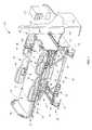
- FIG. 1is a perspective, partial schematic view of an embodiment of a patient support apparatus, configured in accordance with one or more principles of the present disclosure
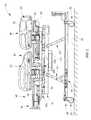
- FIG. 2is a side elevation view of the patient support of FIG. 1 , showing the deck support in an upper position and the deck sections in a linear relationship or bed configuration;
- FIG. 3is a side elevation view of the patient support of FIG. 1 , showing the deck support in an upper position, a head section of the deck elevated by a head section actuator and a seat section of the deck elevated by a seat section actuator;
- FIG. 4is a block diagram of one embodiment of an electronic system for a patient support, configured in accordance with one or more principles of the present disclosure
- FIG. 5is a block diagram of another embodiment of an electronic system of a patient support, configured in accordance with one or more principles of the present disclosure
- FIG. 6is a flow diagram of a method for communication between an electronics system of a patient support and a remote server, according to one or more principles of the present disclosure
- FIG. 7is a schematic diagram of an embodiment of a hospital network with a server and a client patient support apparatus, configured in accordance with one or more principles of the present disclosure.
- FIG. 8is block diagram of yet another embodiment of an electronic system of a patient support, configured in accordance with one or more principles of the present disclosure.
- a patient support apparatusin one illustrative embodiment, includes an electronic control system with client browser software running on a general purpose operating system that connects with a remote server via a high speed network connection.
- the browser and operating systemallow the patient support apparatus to access and run programs not designed exclusively for patient support apparatus electronics systems.
- a general purpose microprocessoralong with network converter circuitry allows the patient support to deliver messages in frames having intended recipient addresses.
- the microprocessorcommunicates with one or more graphical user interfaces and with a control system that controls actuators of the patient support apparatus.
- the control systemmay comprise networked nodes, such as CAN (controller area network), LON (local operating network), USB (universal serial bus), or Ethernet nodes, for example.
- Isolation circuitryisolates the patient support from a network of a care facility with which it communicates.
- a connector for a personal storage deviceis provided on the patient support, such as at a siderail or endboard, for downloading or uploading data and files.
- Other embodiments incorporating one or more of these featuresare possible.
- FIGS. 1-3A patient support 10 according to an illustrative embodiment of the present invention is shown in FIGS. 1-3 .
- Patient support 10includes a frame 12 , a mattress 14 supported by frame 12 , a headboard 16 , a footboard 18 , a pair of head end siderails 20 , and a pair of foot end siderails 22 .
- Frame 12includes a deck support 24 and a deck 26 supporting mattress 14 .
- Deck support 24includes a base frame 28 supported on the floor 29 by a plurality of caster wheels 30 , an intermediate frame 32 , first and second pairs of lift arms 34 configured to raise and lower intermediate frame 32 relative to base frame 28 , and a weigh frame 36 supported by intermediate frame 32 , so as to allow the patient support 10 to be raised and lowered to any position between a high and a low position.
- Deck 26is supported by weigh frame 36 and is configured to articulate between a plurality of positions. More particularly, deck 26 illustratively includes a head section 38 pivotably coupled to weigh frame 32 , a seat section 40 pivotably coupled to weigh frame 32 , and an adjustable length leg section 42 pivotably coupled to seat section 40 .
- the deck 26is illustrated in a first configuration in FIGS. 1 and 2 , while the deck 26 is illustrated in a second configuration in FIG. 3 . In the first configuration of FIGS. 1 and 2 , head section 38 , seat section 40 , and leg section 42 are in a substantially linear or planar relationship. In the second configuration of FIG.
- head section 38 of deck 26is elevated by a head section actuator 43 a and seat section 40 of deck 26 is elevated by a seat section actuator 43 b .
- a leg section actuator 43 cis likewise configured to move leg section 42 relative to seat section 40 .
- An extension actuator 44is configured to extend and retract the adjustable length leg section 42 .
- Head end siderails 20are coupled to head section 38 of deck 26 and can be moved relative to mattress 14 between raised and lowered positions.
- Foot end siderails 22are coupled to weigh frame 32 and can also be moved relative to mattress 14 between raised and lowered positions.
- the illustrative embodiment of FIG. 1further includes an electronics system 110 located primarily beneath the deck 26 of the bed 10 .
- the electronics system 110 of this embodimentcontrols client browser software, shown on display 50 .
- the browser softwarein conjunction with electronics system hardware, allows the bed 10 to serve as a client device to a remote server 111 , shown outside of wall 112 .
- the electronics systemsends requests to server 111 for a task to be performed, via network connection 114 and network connector 115 (e.g., a jack).
- the serverthen runs an application in response to the request, and return data and/or images to be displayed back to the electronics system 110 .
- the system 110then displays the data and/or images as screens or pages on a client browser application displayed on user interface 50 located in or on the siderail 20 .
- the server 111runs a variety of off-the-shelf software applications, such as hospital information system applications and/or home computing applications, not specifically designed for beds or patient supports.
- the electronics system 110 of the bed 10is configured with hardware and software to allow such applications to be displayed and controlled by a user (caregiver and/or patient) of the bed 10 .
- the electronics system 110 of the bed 10also controls bed control software, user interfaces for which are shown on second display 52 .
- the bed control softwareallows the user to move various portions of the bed. For example, as shown in FIG. 3 , the foot, thigh, seat, and head sections of deck 26 can be moved relative to the base frame 28 , such as via electric linear actuators 43 a , 43 b , and 43 d .
- the usercan provide inputs to the bed control software via the display 52 , to cause movement of the bed actuators, and/or to set alarm levels at which the bed will sound and/or show an alarm state.
- the displaycan be a touchscreen, for example, or can have associated buttons to enable the inputs to be made to the control software.
- the electronics system 110includes isolation circuitry to isolate the server 111 and connection 114 and connector 115 from the remainder of the electronics system and associated bed components. Such circuitry is operated using inductive, capacitive, magnetic, and/or optical isolation components, for example.
- the isolatorcomprises an isolator that isolates an Ethernet signal, or a digital isolator that isolates a processor signal from the signal provided at the connector 115 .
- the siderail 20includes a USB port 120 that allows a user to connect to the electronics system 110 .
- the usercould save data via the universal serial bus (USB) port 120 , as controlled by the browser on graphical user interface 50 .
- USBuniversal serial bus
- the usercan load software onto the electronics system 110 via the USB port 120 , such as for example to update the control software, to load user applications, transfer files, or to trouble shoot the electronics 110 .
- the usercould load data from the USB port 120 into the electronics system 110 , indicative of the desired settings of the bed 10 (head deck angle, bed height, desired therapy) and/or other hospital preferences regarding the room, food, or facilities.
- USB portvarious types of user/programmer data ports (serial, parallel, firewire, RS standard ports, IEEE standard ports, USB, etc) could be provided on the bed 10 , and at various locations (frame, deck, headboard, footboard, etc).
- the portcould be on another siderail 22 or 18 , or on the frame 28 or 32 , or on an electronics control box for the system 110 .
- a room identification transmitter 122is provided in or on wall 112 to provide an indication of which room the bed is in. This can be achieved by sending a room identification signal to the bed which then communicates that signal on to the network server, or by sending the bed data and the room identification signal along the same channel, grouped together, or otherwise with some association that allows the server 111 to match the bed and bed data to the appropriate room. Therefore, such association can allow the server 111 to associate data related to the bed 10 or the room with the patient known to be assigned to that room.
- the room identifier signalis sent from the identification transmitter 122 over the cable 114 , through the connector 115 to the electronics system 110 .
- the system 110then relays the room identifier back through the cable 114 along with the network signal that goes back to the server 111 .
- the bed 10tells the network server 111 which room it is in, so that appropriate associations of bed data to patient can be made and so appropriate alarming can be set.
- the servercan set certain bed alarm levels based on whether the patient is a falls risk.
- a falls risk patientmight require all siderails up, all brakes set, bed in low height, and patient position monitor set.
- the server 111can generate an alarm signal sent back through the network connection 114 to the bed, to sound an alarm at the bed 10 and/or at a nurses station or audio station connected to the network.
- the server 111can initiate or request percussion, vibration, or rotation therapy via the browser on display 50 .
- Server 111can also provide other services for the users of the bed 10 , such as network access to a variety of software applications providing entertainment, data, information, multimedia, audio, video, and communications services on client display 50 .
- the usermight access audio files such as MP3 music files, video files such as MPEG movie files, information files such as patient care instructions, e-communication services such as email, audio communications such as voice over internet communications, and/or other network services provided by intranet, extranet, LAN, WAN, or other network hardware.
- Such accessmay be software restricted, such as by a access control application (e.g., a filtering program) that limits access to certain sites or site types, and to certain files, file sizes, or file types. For instance, a preapproved list of allowed network or Internet links can be provided by the access control application, and access can be provided only through predetermined icons or links.
- a access control applicatione.g., a filtering program
- deck support 24includes a base frame 28 supported on the floor 29 by a plurality of caster wheels or caster devices 30 , an intermediate frame 32 , first and second pairs of lift arms 34 configured to raise and lower intermediate frame 32 relative to base frame 28 , and a weigh frame 36 supported by intermediate frame 32 .
- Linear actuators 48 a and 48 bshown in FIG. 3 , provide power to actuate lift arms 34 and in turn to raise and lower intermediate frame 32 relative to base frame 28 .
- Siderails 20 , 22can include a series of buttons for controlling the various functions of hospital bed 10 via the control program, in conjunction with or as alternatives to graphical user interface 52 .
- Deck 26can include head, back, seat, and foot portions or sections that can be tilted relative to intermediate frame 32 and several mechanisms configured to adjust the angular position of these deck sections.
- leg section of deck 26is extendable and can be raised while the thigh section pivots relative the seat.
- head section of deck 26can also be tilted relative to intermediate frame 32 .
- the lift arms 34raise and lower the deck 26 relative to the base frame 28 .
- FIG. 4is a block diagram of an electronic control system 110 that provides control of various functions of a patient support, and which could be used for the electronics control system 110 of FIGS. 1-3 .
- Control system 110operates and monitors linear actuator 44 to extend and retract adjustable length leg section 42 , and linear actuators 48 to move intermediate frame 32 relative to base frame 28 .
- Control system 110further operates and monitors linear actuators 43 a , 43 b and 43 c to move head section 38 relative to weigh frame 36 , seat section 40 relative to weigh frame 36 , and leg section 42 relative to seat section 40 , respectively.
- Control system 110includes a plurality of input devices including graphical user interfaces 50 , 52 , and foot pedal controls 56 coupled to base frame 28 .
- Control system 110also includes an interference detection device 55 , such as optical or switch based obstacle detection systems, coupled to base frame 28 to detect possible clearance issues between intermediate frame 32 and base frame 28 .
- Control system 110further illustratively includes a plurality of actuator position detectors or motor sensors (not shown) provided with each of the plurality of actuators 43 a , 43 b , 43 c , 44 , 48 .
- a plurality of load cells 59are provided between weigh frame 36 and intermediate frame 32 to provide signals that indicate the weight supported by intermediate frame 32 . Control system 110 uses these signals to determine the weight of a patient positioned on mattress 14 .
- control system 110includes a plurality of siderail position detectors or sensors 57 configured to provide signals indicative of the vertical position of siderails 20 , 22 .
- a controller area network system 2220executes a control program 224 to control the various actuators and components.
- a systemcan include one or more controller area network (CAN) controller nodes to control the various actuators. If multiple controller nodes are utilized, the nodes can communicate with one another via serial bus connections.
- CANcontroller area network
- the control programcan comprise control software or other logic that indicates desired control logic for the bed, such as which actuators to operate in response to which user inputs, what sensor to display on the user interfaces 50 , 52 at what times, how to convert data from load cells 59 into patient weight, and what alarms to sound via speaker 201 and/or user interfaces 50 , 52 in response to which sensor inputs (siderails up/down, brakes set/notset, bed low/notlow, patient position).
- the control program 224could be stored in this example in the electronic system of the bed (for example in electronics system 110 of the example bed of FIG. 1 ).
- the electronics system 2220comprises two control boards, one of which receives inputs from user input devices and which stores the control program 224 , and the other of which receives inputs from the user input control board and translates the inputs into corresponding appropriate signals that can be used by the actuators.
- a microprocessor 200controls operation of the displays 50 and 52 , as well as communicates with the bed control system 2220 via a CAN interface circuit 220 .
- the CAN interface 220allows the microprocessor 200 to deliver input commands to the control system 2220 to move an actuator or set an alarm signal.
- the interface 220likewise allows the CAN control system 2220 to deliver actuator status information and other information to the microprocessor 200 , which can then be displayed on displays 50 and 52 as desired.
- the CAN interface 220comprises appropriate circuitry or integrated circuitry that allows the microprocessor 200 to communicate with control system 2220 .
- CAN interface 220can comprise for example, a high speed CAN transceiver.
- the microprocessor 200communicates with hospital server 111 and further is configured to allow the system 110 to act as a client to the server 111 .
- Microprocessor 200accesses nonvolatile memory 204 in which is stored client browser software and a general purpose operating system.
- the general purpose operating systemcan comprise an operating system available for a variety of applications unrelated to patient support apparatus, such as for home computing applications, and/or other industrial applications.
- the Windows CE® operating system or the Linux operating systemcan be utilized.
- Such operating systemscan include a plurality of drivers for operating a variety of peripheral equipment, such as storage devices, printers, scanners, or other equipment.
- Such operating systemscan also be capable of loading and running a variety of standard pre-existing applications that might not be designed for patient support apparatus.
- the client browsercan comprise Internet Explorer®, FireFox®, or other suitable browser.
- the nonvolatile memorycan comprise flash memory, a harddrive, or other suitable memory device, and can have a size of at least 64 MB.
- the operating system and browsercan be executed by the processor 200 by utilizing and accessing volatile memory 2020 , which can comprise RAM memory having a size of at least 128 MB.
- Microprocessorcan comprise a variety of general purpose industrial processors, such as for example i.MX series processors available from FreeScale Semiconductor, Inc. and can have an operating speed of at least about 300 MHz. Such processors may have integrated CAN communication capability and interfaces, if CAN electronics are used on the bed. However, a separate CAN interface can be utilized if the processor does not have integrated CAN capability.
- Microprocessor 200communicates with and drives the graphical user interfaces 50 , 52 via display interfaces 209 .
- Such interfaces 209can comprise low voltage differential signaling transmitters and i2c buffer circuits, and/or other appropriate driver or interface circuitry for driving displays.
- microprocessor 200drives a speaker amplifier 205 to permit audio through a speaker 201 .
- Microprocessor 200also receives audio input from a microphone 211 via a microphone amplifier 203 . Accordingly, alarms, music, nature sounds and other sounds can be driven by microprocessor 200 through speaker 201 and/or user interfaces 50 / 52 . Additionally, audio input can be picked up via microphone 211 and stored via processor 200 .
- microprocessor 200includes an integrated Ethernet interface. Accordingly, the microprocessor 200 can automatically provide output data for communication to a network in an Ethernet format.
- the formatincludes frames having a header, data section, and footer.
- the headercontains the Media Access Control (MAC) addresses of both the sender and intended network recipient.
- MACMedia Access Control
- microprocessor 200first performs a check on whether the connection is available to transmit. If a collision is detected (another device on the network has sent an Ethernet frame at the same time), then processor 200 will retransmit the frame after waiting a random time period up to a maximum time period. While the processor 200 has built-in Ethernet communication output in this example, a separate circuit or card could be used for this purpose.
- the example of FIG. 4further shows that the electronics system 110 of the patient support includes a WiFi interface 208 .
- This interface 208allows the processor 200 to communicate to the server 111 (and/or to other equipment) via a wireless local area network communication protocol, such as the IEEE 802.11 protocol.
- the wireless connectioncan utilize spread spectrum and/or frequency division multiplexing and can operate at a frequency of at least 900 MHz, such as 1 GHz and higher for example. For example, the wireless connection could be about 2.4 GHz.
- Isolator 210can provide electrical isolation via inductive, capacitive, and/or optical isolation circuitry.
- the isolator 210provides at least 4.6 mm creepage distance, 2.5 mm of air clearance, and 1500 volts dielectric breakdown voltage. (Air clearance is the shortest distance through the air between two conductive elements. Creepage distance is the shortest distance on the surface of the insulating material between two conductive elements.)
- the isolation capability of isolator 210provides at least 8.0 mm creepage distance, 2.5 mm of air clearance, and 5000 volts dielectric breakdown voltage.
- the isolator 210has at least 2.5 mm creepage distance and at least 2.0 mm air clearance, such as at least 4.0 mm creepage and 2.5 mm air clearance for example.
- an Ethernet interface 212which provides any necessary conversion of the isolator's signal into Ethernet protocol (such as that described above).
- the interface 212can be a serial to Ethernet converter that converts or processes the serial signal to produce the desired Ethernet format (and vice versa).
- Ethernet magnetics 214Connected to the interface 212 are Ethernet magnetics 214 , which provide electric isolation, distortion removal and EMI suppression. The signal is then provided as an Ethernet signal at an Ethernet jack or connector 216 , is hardwired to the server 111 .
- FIG. 5is a block diagram of an illustrative embodiment of an electronics control system 2000 for a patient support.
- a microprocessor 202runs an operating system storage on nonvolatile ROM memory 204 using volatile RAM memory 206 .
- the operating systemmay comprise a general purpose, off-the shelf operating system not designed specifically for patient supports, such as a Windows® operating system from Microsoft, for example.
- the ROM memory 204may also include browser software.
- the operating system and/or browsercan allow the system 2000 to act as a client to a remote server when communicating with such server.
- a Codec device 2010converts a digital data stream from the microprocessor 202 into an analog signal for use by a speaker amplifier 207 which drives speakers 209 R and 209 L.
- the Codec device 2010converts analog signals generated by a microphone 211 (and amplified by a microphone amplifier 203 ) into digital signals for use by the processor 202 .
- the microprocessor 202controls patient support functions through interfaces to patient support actuator electronics, runs graphical user interface functions through interfaces to user interfaces, communicates with a remote network through one or more network interfaces, and drives a removable storage device. More details on the various circuits of this illustrative embodiment that allow such functions are provided in the following description.
- Two CAN interfaces 220 and 222are provided in this illustrative embodiment, and these provide connectivity to a patient support actuator control electronics. These transceivers 220 , 222 provide commands from the microprocessor to the CAN network, or other device network, which then control the actuators (e.g., pumps, motors, linear actuators, blowers, sensors, etc) that allow the patient support to move, provide therapy, protect, and/or sense.
- actuatorse.g., pumps, motors, linear actuators, blowers, sensors, etc.
- Display driver circuits 230 , 231 , 232 , and 233are provided and drive graphical user interfaces, such as touchscreens, LCD's and other displays.
- graphical user interfacessuch as touchscreens, LCD's and other displays.
- an LVDS circuit 230 and an I2C buffer 231drive a first GUI
- LVDS circuit 232 and I2C buffer 233drive a second GUI.
- a network interface circuitis also provided.
- the interface circuitinterfaces with a remote network computer (remote from the patient's room).
- the network interfacecomprises a serial to Ethernet converter 240 which converts serial signals from the processor 202 into Ethernet signals.
- converter 240could comprise an Ethernet interface board or chip.
- processor 202comprises a processor with built-in Ethernet communication capability.
- the output of the converter 240is provided to Ethernet magnetics 242 which then provides the Ethernet signal to jack or connector 244 .
- the connector 244is an RJ45 Ethernet jack.
- An Ethernet cablecan then be connected from the network to the connector 244 to allow for communications with the patient support electronics 2000 .
- Electric isolators 246provide electrical isolation of the electronics 2000 from the network.
- the isolators 246operate on digital signals and therefore are digital isolators.
- the isolators 246provide such isolation via inductance by using microtransformers that can convert digital signals at high speed.
- the isolator 210has at least 4 mm creepage distance and 2.4 mm of air clearance, and can isolate at least up to 240 volts AC in one embodiment.
- the isolator 210has greater than 2.0 mm creepage distance and greater than 2.0 mm of air clearance.
- the isolator 210has at least 2.5 mm creepage distance and at least 2.5 mm air clearance.
- the isolator 210has a creepage distance and air clearance greater than that of Ethernet magnetics 242 .
- An identifier of the room in which the patient support is locatedis also provided to the processor 202 via lines 248 . These lines are isolated via the isolator 246 .
- the room identificationmay come from a wall unit at the network connection and may be carried by the same cable that carries the network signal to the connector 244 . Alternatively, the room ID may be provided via different communication paths.
- the processor 202may then transfer the room identifier back to the network via the connector 244 .
- the signalmay be provided in the network communication packet, or over a separate dedicated line (such as transmit line 248TX)
- a USB connector(e.g., outlet, port, or jack) is provided in this example, as shown at 250 .
- the USB connector 250allows data to be stored by the processor 202 on a portable removable card or memory device or stick, and also to be transferred from the card or device or stick to the processor 202 for use by the processor 202 .
- Such datamay include patient data, patient support data, multimedia data, audio data, video data, email data, document data, or other data or information useful to the caregiver, hospital, or patient.
- the USB connector 250can be used to upgrade or modify the programs and operating system in memory 204 .
- the connector 250can also be used to connect the patient support to other medical devices such as pumps, ventilators, or monitors, or to other consumer electronics devices, such as phones, cameras, PDA's, personal computers, MP3 players, electronic book devices, and the like.
- Power to the circuit 2000can be provided by power converter 2100 which can provide various power levels needed as appropriate. This power can also be passed on to other devices, such as via power outputs 2110 .
- a clock signalcan be provided along with data over an integrated data/clock line.
- FIG. 6is a flow diagram of an illustrative method for communication between an electronics system of a patient support and a remote server, according to one or more principles of the present disclosure.
- the patient supportis powered, as shown at operation 300 .
- the general purpose operating system and client browser program and bed control programare then loaded into memory on the patient support, as shown at operation 302 .
- a user of the patient supportenters a url or otherwise indicates the desired service, such as by clicking a link or icon, as shown at operation 304 .
- a touchscreen or other suitable display and input devicecan be used for this purpose.
- a requestis sent to a remote servicer via a network interface to launch the desired remote application or access the desired remote page, as shown at block 306 .
- datais transferred from the remote server to the patient support and the browser software on the patient support displays the screen as instructed by the data from the server.
- the userenters data or selects an icon or location on the screen displayed on the patient support, as shown at operation 310 .
- Data representing the selectionis again transferred from the patient support to the server over the network interface, as shown at operation 312 .
- the network interfacecould include one or more of the interfaces described above, such as isolator 246 , magnetics 242 , connector 244 , converter 240 , and/or Spi to WiFi bridge 249 , or other suitable interface.
- the serverresponds to the user data selection according to the code/program on the server for the selected application.
- Inputis again provided by user at the patient support as shown at block 316 .
- Such inputcan be a command to the patient support apparatus to raise or lower or tilt or inflate or provide therapy, and can be provided via a button or touchscreen.
- the bed control programresponds to this input and controls the appropriate actuator to achieve the desired patient support function, as shown at operation 318 .
- the processis iterative, such that additional commands regarding operation of remote applications from the remote server, and additional commands for control of the patient support can be provided, at any time that the patient support is running.
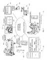
- FIG. 7is a schematic diagram of an illustrative embodiment of hospital network with server and client patient support apparatus, configured in accordance with one or more principles of the present disclosure.
- a patient support with a client software browser 404is connected via a hospital network 400 having servers.
- the network 400is further connected to various third party medical devices, such as monitors or pumps, and third party applications, such as general computing applications, as shown at 422 .
- the network 400is connected to software that keeps track of patient and/or caregiver tasks and locations in the hospital, as shown at 420 , such as which patients are in which rooms.
- Such softwarecould comprise admission, discharge, transfer (ADT) software.
- caregiverscan be provided with portable messaging or alerting devices 418 which are also in communication with the servers, as shown at 418 .
- Such devicescould comprise badges, pagers, telephones, or other communication devices.
- a nurse call system 416can also connect with the network 400 . Additionally, data regarding patient surveillance, such as patient vital signs data can be communicated to the network 400 via the patient support 404 or directly. Moreover, asset management software 412 can be used to track hospital equipment and can run on one or more computers or servers connected to the network 400 . Also, communications regarding support and diagnostics can be delivered via the network 400 . Accordingly, many pieces of software and hardware can communicate through the network 400 .
- the network 400may utilize Internet and/or Ethernet protocols to provide such communications.
- FIG. 8is block diagram of yet another illustrative embodiment of an electronic system of a patient support, configured in accordance with one or more principles of the present disclosure. This embodiment is similar to the embodiment of FIG. 5 . Accordingly, much of the description above regarding FIG. 5 applies with respect to the embodiment of FIG. 8 and will not be repeated here, except for salient differences.
- the display drivers 230 and 232do not include clock lines, because the clock signal is provided over the data lines (DO+ and DO ⁇ ) in this embodiment.
- a touchscreen controller interface 450is provided, to allow the circuit to connect with an external touchscreen (e.g., in the event that the hospital bed does not include a graphical display, a retrofit touchscreen can be provided and can interface to the circuitry through interface 450 ).
- an external touchscreene.g., in the event that the hospital bed does not include a graphical display, a retrofit touchscreen can be provided and can interface to the circuitry through interface 450 ).
- an Ethernet isolator chip 452is provided which electrically isolates the Ethernet signal coming from the connector 244 through the Ethernet magnetics 242 to the processor 202 (and vice versa).
- Such chipcould comprise a 10/100/ and/or 1000 MBit isolation module, such as available through Halo Electronics, CoilCraft Inc and the like, and can provide isolation in accordance with IEC60601-1 specifications, for example.
- a USB connector 460is provided for use by the caregiver and/or patient.
- a USB isolation chip 454is provided and performs electrical isolation of the USB signal that the patient/caregiver accesses.
- the isolation provided by the isolators 452 and 454provides at least 2.5 mm creepage distance and at least 2.0 mm air clearance, such as at least 4.6 mm creepage and 2.5 mm air clearance for example.
- the USB signalis provided to/from the processor 202 via a USB hub 466 .
- the hub 466communicates with the isolator 454 which provides the signal at the connector 460 .
- additional non-isolated USB connectors 462 and 464are also provided, and allow for USB access to the processor 202 by service technicians, and others besides the end user.
- Additional communication ports(USB port 470 and RS232 port 472 ) are provided for programming, updates, service and the like.
Landscapes
- Health & Medical Sciences (AREA)
- Engineering & Computer Science (AREA)
- General Health & Medical Sciences (AREA)
- Public Health (AREA)
- Business, Economics & Management (AREA)
- General Business, Economics & Management (AREA)
- Medical Informatics (AREA)
- Nursing (AREA)
- Life Sciences & Earth Sciences (AREA)
- Animal Behavior & Ethology (AREA)
- Veterinary Medicine (AREA)
- Biomedical Technology (AREA)
- Epidemiology (AREA)
- Primary Health Care (AREA)
- Computing Systems (AREA)
- Computer Networks & Wireless Communication (AREA)
- Signal Processing (AREA)
- Accommodation For Nursing Or Treatment Tables (AREA)
- Invalid Beds And Related Equipment (AREA)
- Measuring And Recording Apparatus For Diagnosis (AREA)
- Selective Calling Equipment (AREA)
Abstract
Description
Claims (20)
Priority Applications (2)
| Application Number | Priority Date | Filing Date | Title |
|---|---|---|---|
| US13/081,587US8618918B2 (en) | 2010-04-09 | 2011-04-07 | Patient support, communication, and computing apparatus including movement of the support and connection to the hospital network |
| US14/134,145US9253259B2 (en) | 2010-04-09 | 2013-12-19 | Patient support, communication, and computing apparatus |
Applications Claiming Priority (2)
| Application Number | Priority Date | Filing Date | Title |
|---|---|---|---|
| US32239210P | 2010-04-09 | 2010-04-09 | |
| US13/081,587US8618918B2 (en) | 2010-04-09 | 2011-04-07 | Patient support, communication, and computing apparatus including movement of the support and connection to the hospital network |
Related Child Applications (1)
| Application Number | Title | Priority Date | Filing Date |
|---|---|---|---|
| US14/134,145ContinuationUS9253259B2 (en) | 2010-04-09 | 2013-12-19 | Patient support, communication, and computing apparatus |
Publications (2)
| Publication Number | Publication Date |
|---|---|
| US20110247139A1 US20110247139A1 (en) | 2011-10-13 |
| US8618918B2true US8618918B2 (en) | 2013-12-31 |
Family
ID=44279906
Family Applications (2)
| Application Number | Title | Priority Date | Filing Date |
|---|---|---|---|
| US13/081,587Active2032-06-20US8618918B2 (en) | 2010-04-09 | 2011-04-07 | Patient support, communication, and computing apparatus including movement of the support and connection to the hospital network |
| US14/134,145Active2031-08-18US9253259B2 (en) | 2010-04-09 | 2013-12-19 | Patient support, communication, and computing apparatus |
Family Applications After (1)
| Application Number | Title | Priority Date | Filing Date |
|---|---|---|---|
| US14/134,145Active2031-08-18US9253259B2 (en) | 2010-04-09 | 2013-12-19 | Patient support, communication, and computing apparatus |
Country Status (3)
| Country | Link |
|---|---|
| US (2) | US8618918B2 (en) |
| EP (1) | EP2374439A3 (en) |
| JP (1) | JP5917821B2 (en) |
Cited By (18)
| Publication number | Priority date | Publication date | Assignee | Title |
|---|---|---|---|---|
| US20110247135A1 (en)* | 2010-04-09 | 2011-10-13 | Fred Herman | Siderail power communication interface |
| US20140080413A1 (en)* | 2012-09-17 | 2014-03-20 | Stryker Corporation | Communication systems for patient support apparatuses |
| US9253259B2 (en) | 2010-04-09 | 2016-02-02 | Hill-Rom Services, Inc. | Patient support, communication, and computing apparatus |
| US9539155B2 (en) | 2012-10-26 | 2017-01-10 | Hill-Rom Services, Inc. | Control system for patient support apparatus |
| US9833194B2 (en) | 2013-03-15 | 2017-12-05 | Stryker Corporation | Patient support apparatus with remote communications |
| US10004654B2 (en) | 2014-03-11 | 2018-06-26 | Hill-Rom Services, Inc. | Patient bed having software download capability |
| US10235845B2 (en) | 2017-04-05 | 2019-03-19 | Stryker Corporation | Patient support apparatuses with reconfigurable communication |
| US20190192368A1 (en)* | 2017-12-22 | 2019-06-27 | Stryker Corporation | Techniques For Notifying Persons Within A Vicinity Of A Patient Support Apparatus Of A Remote Control Function |
| US10456309B2 (en) | 2017-08-09 | 2019-10-29 | Stryker Corporation | Field configurable patient support apparatuses |
| US10474808B2 (en) | 2013-03-29 | 2019-11-12 | Hill-Rom Services, Inc. | Hospital bed compatibility with third party application software |
| US10543137B2 (en) | 2013-03-15 | 2020-01-28 | Stryker Corporation | Patient support apparatus with remote communications |
| US10582981B2 (en) | 2016-02-02 | 2020-03-10 | Stryker Corporation | Accessory support and coupling systems for an accessory support |
| US10757228B1 (en) | 2017-02-28 | 2020-08-25 | Stryker Corporation | Patient care devices with on-board network communication |
| US10945902B2 (en) | 2017-11-13 | 2021-03-16 | Stryker Corporation | Techniques for controlling actuators of a patient support apparatus |
| US10980689B2 (en) | 2017-07-14 | 2021-04-20 | Stryker Corporation | Patient support apparatuses with personal electronic device charging |
| US11066090B2 (en)* | 2015-10-13 | 2021-07-20 | Globus Medical, Inc. | Stabilizer wheel assembly and methods of use |
| US11389354B2 (en) | 2017-11-30 | 2022-07-19 | Stryker Corporation | Multi-function headboard for patient support apparatus |
| US11837363B2 (en) | 2020-11-04 | 2023-12-05 | Hill-Rom Services, Inc. | Remote management of patient environment |
Families Citing this family (29)
| Publication number | Priority date | Publication date | Assignee | Title |
|---|---|---|---|---|
| JPH0648371B2 (en) | 1986-11-07 | 1994-06-22 | 富士写真フイルム株式会社 | Processing method of silver halide photographic light-sensitive material for X-ray |
| US9937090B2 (en)* | 2005-03-29 | 2018-04-10 | Stryker Corporation | Patient support apparatus communication systems |
| US9959471B2 (en) | 2008-05-06 | 2018-05-01 | Careview Communications, Inc. | Patient video monitoring systems and methods for thermal detection of liquids |
| US20170155877A1 (en)* | 2008-05-06 | 2017-06-01 | Careview Communications, Inc. | System and method for predicting patient falls |
| DE202010012910U1 (en) | 2010-11-16 | 2012-02-17 | Dewert Antriebs- Und Systemtechnik Gmbh | Electromotive furniture drive |
| CN103476378A (en)* | 2011-04-12 | 2013-12-25 | 利纳克有限公司 | Electric actuator system |
| US9320662B2 (en)* | 2011-10-18 | 2016-04-26 | Stryker Corporation | Patient support apparatus with in-room device communication |
| US8707483B2 (en) | 2011-10-26 | 2014-04-29 | Hill-Rom Services, Inc. | Therapy enabler system |
| DE102011055362A1 (en)* | 2011-11-15 | 2013-05-16 | Dewert Antriebs- Und Systemtechnik Gmbh | Arrangement with an electromotive furniture drive and a data device; A method for establishing a communication connection between the electromotive furniture drive and the data device; and a corresponding furniture drive |
| US9569591B2 (en)* | 2012-05-31 | 2017-02-14 | Hill-Rom Services, Inc. | Configurable user interface systems for hospital bed |
| WO2014051563A1 (en)* | 2012-09-26 | 2014-04-03 | Draeger Medical Systems, Inc. | Medical sensor cradle |
| US12208216B2 (en) | 2015-09-15 | 2025-01-28 | Sleep Solutions Inc. | System for enhancing sleep recovery and promoting weight loss |
| US11883606B2 (en) | 2013-03-15 | 2024-01-30 | Sleep Solutions Inc. | Stress reduction and sleep promotion system |
| US11813076B2 (en) | 2013-03-15 | 2023-11-14 | Sleepme Inc. | Stress reduction and sleep promotion system |
| US11602611B2 (en) | 2013-03-15 | 2023-03-14 | Sleepme Inc. | System for enhancing sleep recovery and promoting weight loss |
| US11812859B2 (en) | 2013-03-15 | 2023-11-14 | Sleepme Inc. | System for enhancing sleep recovery and promoting weight loss |
| US11896774B2 (en) | 2013-03-15 | 2024-02-13 | Sleep Solutions Inc. | System for enhancing sleep recovery and promoting weight loss |
| US11013883B2 (en) | 2013-03-15 | 2021-05-25 | Kryo, Inc. | Stress reduction and sleep promotion system |
| US10986933B2 (en)* | 2013-03-15 | 2021-04-27 | Kryo, Inc. | Article comprising a temperature-conditioned surface, thermoelectric control unit, and method for temperature-conditioning the surface of an article |
| US10290071B2 (en)* | 2013-03-29 | 2019-05-14 | Hill-Rom Services, Inc. | Universal caregiver interface |
| JP6685790B2 (en)* | 2016-03-24 | 2020-04-22 | パラマウントベッド株式会社 | Sleeper device |
| JP2018015067A (en)* | 2016-07-25 | 2018-02-01 | パラマウントベッド株式会社 | Bed fence |
| CN106790419A (en)* | 2016-12-01 | 2017-05-31 | 江苏物联网研究发展中心 | Care bed intelligent management system |
| US10500401B2 (en)* | 2016-12-06 | 2019-12-10 | Stryker Corporation | Network communication for patient support apparatuses |
| US11103398B2 (en)* | 2017-05-17 | 2021-08-31 | Hill-Rom Services, Inc. | Flexible overhead arm |
| US11410771B2 (en) | 2017-06-01 | 2022-08-09 | Stryker Corporation | Patient care devices with open communication |
| JP7118104B2 (en)* | 2020-04-01 | 2022-08-15 | パラマウントベッド株式会社 | sleeping device |
| WO2022146693A1 (en)* | 2020-12-29 | 2022-07-07 | Stryker Corporation | Tool for configuring headwall units used for patient support apparatus communication |
| EP4252731A1 (en)* | 2022-03-30 | 2023-10-04 | Baxter Medical Systems GmbH + Co. KG | Surgical table control device |
Citations (167)
| Publication number | Priority date | Publication date | Assignee | Title |
|---|---|---|---|---|
| US3643219A (en) | 1970-03-13 | 1972-02-15 | Raytheon Co | Visual display system |
| US3910659A (en) | 1974-07-08 | 1975-10-07 | Joerns Furniture Co | Reversible overbed table and mirror |
| US3946159A (en) | 1973-03-23 | 1976-03-23 | Vital Signs, Incorporated | Hospital communication system |
| US4356475A (en) | 1980-09-12 | 1982-10-26 | Siemens Aktiengesellschaft | System containing a predetermined number of monitoring devices and at least one central station |
| US4410158A (en) | 1980-07-28 | 1983-10-18 | Maffei Eugene R | Over-bed television support frame |
| US4452499A (en) | 1981-02-20 | 1984-06-05 | Zumtobel Gmbh & Co. | Service stand for work area |
| US4489454A (en) | 1980-01-29 | 1984-12-25 | Thompson James C | Portable hinged transducer carrier |
| US4557453A (en) | 1984-05-25 | 1985-12-10 | Mccloskey Glenn A | Gurney attachment |
| EP0168158A2 (en) | 1984-06-08 | 1986-01-15 | Hauserman Inc. | Table |
| US4584989A (en) | 1984-12-20 | 1986-04-29 | Rosemarie Stith | Life support stretcher bed |
| US4607897A (en) | 1985-07-08 | 1986-08-26 | Schwartz C Bruce | Videoendoscopic support stand |
| US4640485A (en) | 1984-06-08 | 1987-02-03 | International Business Machines Corporation | Adjustable support for display monitor |
| US4687167A (en) | 1985-10-23 | 1987-08-18 | Skalka Gerald P | Multi-position computer support |
| US4708312A (en) | 1985-10-23 | 1987-11-24 | Ncr Corporation | Extensible height-adjustable swivel arm for supporting a display or the like |
| US4715385A (en) | 1986-09-26 | 1987-12-29 | Marquette Electronics, Inc. | Patient monitoring system having transportable data module and display unit |
| US4724555A (en) | 1987-03-20 | 1988-02-16 | Hill-Rom Company, Inc. | Hospital bed footboard |
| US4738369A (en) | 1983-08-05 | 1988-04-19 | Desjardins Wallace H | Ceiling support for patient monitoring equipment |
| US4747172A (en) | 1984-11-02 | 1988-05-31 | Penox Technologies, Inc. | Medical device transporter |
| US4756706A (en) | 1985-01-23 | 1988-07-12 | American Hospital Supply Corporation | Centrally managed modular infusion pump system |
| US4768241A (en) | 1987-02-24 | 1988-09-06 | Beney Daniel R | Self contained, mobile intensive care bed structure |
| US4783036A (en) | 1987-04-16 | 1988-11-08 | Anthro Corporation | Adjustable support |
| US4835372A (en) | 1985-07-19 | 1989-05-30 | Clincom Incorporated | Patient care system |
| US4836478A (en) | 1987-10-15 | 1989-06-06 | Ergotron, Inc. | Suspension system for personal computers and monitors |
| US4848710A (en) | 1988-06-20 | 1989-07-18 | Newman David A H | Support device |
| US4852500A (en) | 1987-03-18 | 1989-08-01 | Herman Miller, Inc. | Integrated computer implement work area |
| US4857713A (en) | 1986-02-14 | 1989-08-15 | Brown Jack D | Hospital error avoidance system |
| US4872679A (en) | 1988-12-06 | 1989-10-10 | Bohaski Frank L | Combination table top football and hockey game |
| GB2218149A (en) | 1988-05-05 | 1989-11-08 | Ming Ming Aluminium Co Limited | Equipment mounting arm |
| US4890856A (en) | 1987-02-18 | 1990-01-02 | Smm Sportive Management Und Marketing Gmbh | Golf cart |
| US4934933A (en) | 1989-02-21 | 1990-06-19 | Jack Fuchs | Dental work station |
| US4945592A (en) | 1988-09-30 | 1990-08-07 | The General Hospital Corporation | Transport system for portable patient care apparatus |
| US4981139A (en) | 1983-08-11 | 1991-01-01 | Pfohl Robert L | Vital signs monitoring and communication system |
| US4993683A (en) | 1987-12-23 | 1991-02-19 | F. M. K. Kreuzer Gmbh & Co. Kg | Overhead support for medical appliances |
| US5023967A (en) | 1988-03-23 | 1991-06-18 | American Life Support Technology | Patient support system |
| US5036852A (en) | 1989-12-08 | 1991-08-06 | Leishman Mark L | Medical equipment monitor apparatus and method |
| US5072906A (en) | 1988-01-15 | 1991-12-17 | Hill-Rom Company, Inc. | Hospital bed with pivoting headboard |
| US5077843A (en) | 1990-07-28 | 1992-01-07 | Hill-Rom Company, Inc. | Hospital bed and assemblies of hospital care apparatus |
| US5108063A (en) | 1990-11-01 | 1992-04-28 | Hill-Rom Company, Inc. | Hospital room computer mounting arm |
| US5117521A (en) | 1990-05-16 | 1992-06-02 | Hill-Rom Company, Inc. | Care cart and transport system |
| US5187641A (en) | 1991-10-24 | 1993-02-16 | Critikon, Inc. | Patient monitoring unit and care station |
| US5272318A (en) | 1991-11-18 | 1993-12-21 | Novatek Medical Inc. | Electronically readable medical locking system |
| US5284255A (en) | 1991-08-09 | 1994-02-08 | Hill-Rom Company, Inc. | Pivoted power column |
| US5319816A (en) | 1992-12-07 | 1994-06-14 | Hill-Rom Company, Inc. | IV rack transferrable from an IV stand to a hospital bed |
| US5330415A (en) | 1989-02-27 | 1994-07-19 | Air-Shields, Inc. | Incubator with remote control and display module |
| US5335651A (en) | 1990-05-16 | 1994-08-09 | Hill-Rom Company, Inc. | Ventilator and care cart each capable of nesting within and docking with a hospital bed base |
| US5337845A (en) | 1990-05-16 | 1994-08-16 | Hill-Rom Company, Inc. | Ventilator, care cart and motorized transport each capable of nesting within and docking with a hospital bed base |
| US5357396A (en) | 1989-04-25 | 1994-10-18 | Alm Per V | Earth discharge carrier |
| US5362021A (en) | 1992-05-11 | 1994-11-08 | Phillips Medical Group, Inc. | Multi-adjustable surgical tray apparatus |
| US5375604A (en) | 1992-12-11 | 1994-12-27 | Siemens Medical Electronics, Inc. | Transportable modular patient monitor |
| US5396673A (en) | 1988-01-15 | 1995-03-14 | Hill-Rom Company, Inc. | Hospital bed with pivoting headboard |
| US5400991A (en) | 1992-11-19 | 1995-03-28 | Minnesota Mining And Manufacturing Company | Modular mounting assembly |
| US5407163A (en) | 1993-11-19 | 1995-04-18 | Hill-Rom Company, Inc. | Sliding IV pole |
| US5417222A (en) | 1994-01-21 | 1995-05-23 | Hewlett-Packard Company | Patient monitoring system |
| EP0376066B1 (en) | 1988-12-16 | 1995-08-30 | Telehotel TV-Systeme GmbH | Control apparatus |
| US5473536A (en) | 1994-04-04 | 1995-12-05 | Spacelabs Medical, Inc. | Method and system for customizing the display of patient physiological parameters on a medical monitor |
| US5473997A (en) | 1993-09-09 | 1995-12-12 | Am Fab, Inc. | Overbed table with single bar cantilever support |
| US5494051A (en) | 1994-09-14 | 1996-02-27 | Cardi-Act, L.L.C. | Patient-transport apparatus |
| US5502480A (en) | 1994-01-24 | 1996-03-26 | Rohm Co., Ltd. | Three-dimensional vision camera |
| US5513406A (en) | 1994-04-21 | 1996-05-07 | Hill-Rom Company, Inc. | Modular hospital bed and method of patient handling |
| US5527289A (en) | 1992-04-15 | 1996-06-18 | Hill-Rom Company, Inc. | IV management apparatus |
| US5536084A (en) | 1994-05-09 | 1996-07-16 | Grandview Hospital And Medical Center | Mobile nursing unit and system therefor |
| US5542138A (en) | 1995-02-06 | 1996-08-06 | Williams; Terry N. | Bedside control unit for a hospital bed |
| US5544649A (en) | 1992-03-25 | 1996-08-13 | Cardiomedix, Inc. | Ambulatory patient health monitoring techniques utilizing interactive visual communication |
| US5556065A (en) | 1994-10-19 | 1996-09-17 | Wadley; Robert D. | Intensive care equipment carriage |
| US5561412A (en) | 1993-07-12 | 1996-10-01 | Hill-Rom, Inc. | Patient/nurse call system |
| US5579001A (en) | 1994-10-20 | 1996-11-26 | Hewlett-Packard Co. | Paging-based backchannel in a medical telemetry system |
| US5579775A (en) | 1994-10-20 | 1996-12-03 | Hewlett-Packard Company | Dynamic control of a patient monitoring system |
| US5618090A (en) | 1995-05-12 | 1997-04-08 | Medaes, Inc. | Movable hospital room equipment column |
| US5623925A (en) | 1995-06-05 | 1997-04-29 | Cmed, Inc. | Virtual medical instrument for performing medical diagnostic testing on patients |
| US5630566A (en) | 1995-05-30 | 1997-05-20 | Case; Laura | Portable ergonomic work station |
| US5640953A (en) | 1995-03-09 | 1997-06-24 | Siemens Medical Systems, Inc. | Portable patient monitor reconfiguration system |
| US5651775A (en) | 1995-07-12 | 1997-07-29 | Walker; Richard Bradley | Medication delivery and monitoring system and methods |
| US5664270A (en) | 1994-07-19 | 1997-09-09 | Kinetic Concepts, Inc. | Patient interface system |
| US5687717A (en) | 1996-08-06 | 1997-11-18 | Tremont Medical, Inc. | Patient monitoring system with chassis mounted or remotely operable modules and portable computer |
| US5699038A (en) | 1993-07-12 | 1997-12-16 | Hill-Rom, Inc. | Bed status information system for hospital beds |
| US5712482A (en) | 1996-08-05 | 1998-01-27 | Physics Technology, Inc. | Portable electronic radiographic imaging apparatus |
| US5715138A (en) | 1995-10-19 | 1998-02-03 | Daewoo Electronics Co., Ltd. | Apparatus for providing a display with tilting and rotating movements with rack, pinion, and bevel gears |
| US5732401A (en) | 1996-03-29 | 1998-03-24 | Intellitecs International Ltd. | Activity based cost tracking systems |
| US5732712A (en) | 1996-07-12 | 1998-03-31 | Adair; Edwin L. | Sterile encapsulated operating room video monitor and video monitor support device |
| US5738102A (en) | 1994-03-31 | 1998-04-14 | Lemelson; Jerome H. | Patient monitoring system |
| US5738316A (en) | 1995-04-03 | 1998-04-14 | Ergotron, Inc. | Vertical work center |
| US5743503A (en) | 1996-03-08 | 1998-04-28 | Ergotron, Inc. | Computer suspension system |
| US5752917A (en) | 1996-03-19 | 1998-05-19 | Siemens Medical Systems, Inc. | Network connectivity for a portable patient monitor |
| US5769440A (en) | 1996-03-05 | 1998-06-23 | St. Joseph's Hospital, Inc. | Wheelchair with mobile accessory |
| US5771511A (en) | 1995-08-04 | 1998-06-30 | Hill-Rom, Inc. | Communication network for a hospital bed |
| US5772585A (en) | 1996-08-30 | 1998-06-30 | Emc, Inc | System and method for managing patient medical records |
| US5772599A (en) | 1996-05-09 | 1998-06-30 | Albert Einstein Healthcare Network | Apparatus and method for monitoring a system |
| US5788851A (en) | 1995-02-13 | 1998-08-04 | Aksys, Ltd. | User interface and method for control of medical instruments, such as dialysis machines |
| US5791263A (en) | 1993-07-23 | 1998-08-11 | Weber Knapp Company | Adjustable work surface |
| US5799917A (en) | 1996-12-17 | 1998-09-01 | Li; Chin-Chu | Adjustable supporting bracket |
| US5820623A (en) | 1995-06-20 | 1998-10-13 | Ng; Wan Sing | Articulated arm for medical procedures |
| US5822544A (en) | 1990-07-27 | 1998-10-13 | Executone Information Systems, Inc. | Patient care and communication system |
| US5826846A (en) | 1996-06-28 | 1998-10-27 | Hill-Rom, Inc. | Monitor arm with constant counterbalance |
| US5831816A (en) | 1996-09-30 | 1998-11-03 | Monorail, Inc. | Shock mounting asssembly for use with flat panel displays |
| US5838223A (en) | 1993-07-12 | 1998-11-17 | Hill-Rom, Inc. | Patient/nurse call system |
| US5842672A (en) | 1996-06-07 | 1998-12-01 | Ergotron, Inc. | Mounting system for flat panel display, keyboard and stand |
| US5876008A (en) | 1995-01-17 | 1999-03-02 | Ergotron, Inc. | Suspension system for video monitor or other equipment |
| US5883370A (en) | 1995-06-08 | 1999-03-16 | Psc Inc. | Automated method for filling drug prescriptions |
| US5889568A (en) | 1995-12-12 | 1999-03-30 | Rainbow Displays Inc. | Tiled flat panel displays |
| US5895354A (en) | 1996-06-26 | 1999-04-20 | Simmons; Paul L. | Integrated medical diagnostic center |
| US5895571A (en) | 1994-09-07 | 1999-04-20 | Medisystems Technology Corporation | Separable hemodialysis system connected by a movable arm |
| US5898961A (en) | 1995-06-07 | 1999-05-04 | Hill-Rom, Inc. | Mobile support unit and attachment mechanism for patient transport device |
| US5903211A (en) | 1997-02-07 | 1999-05-11 | Althin Medical, Inc. | Medical treatment device with a user interface adapted for home or limited care environments |
| US5907291A (en) | 1997-06-05 | 1999-05-25 | Vsm Technology Inc. | Multi-patient monitoring apparatus and method |
| US5918331A (en) | 1994-08-05 | 1999-07-06 | Buchanan Aircraft Corporation Limited | Portable intensive care unit with medical equipment |
| US5918328A (en) | 1996-07-29 | 1999-07-06 | Ramsey; Nathan R. | Bed attached swivel socket crane lift assembly |
| GB2333391A (en) | 1998-01-20 | 1999-07-21 | Samsung Display Devices Co Ltd | Multi-display monitor |
| US5944659A (en) | 1995-11-13 | 1999-08-31 | Vitalcom Inc. | Architecture for TDMA medical telemetry system |
| US5960085A (en) | 1997-04-14 | 1999-09-28 | De La Huerga; Carlos | Security badge for automated access control and secure data gathering |
| US5957838A (en) | 1996-07-02 | 1999-09-28 | Instrumentarium Oy | Patient monitoring system |
| US5966760A (en) | 1997-01-31 | 1999-10-19 | Hill-Rom, Inc. | Apparatus and method for upgrading a hospital room |
| US5973598A (en) | 1997-09-11 | 1999-10-26 | Precision Dynamics Corporation | Radio frequency identification tag on flexible substrate |
| US5978211A (en) | 1996-11-06 | 1999-11-02 | Samsung Electronics Co., Ltd. | Stand structure for flat-panel display device with interface and speaker |
| US5975081A (en) | 1996-06-21 | 1999-11-02 | Northrop Grumman Corporation | Self-contained transportable life support system |
| US5993006A (en) | 1997-06-06 | 1999-11-30 | Denso Corporation | Apparatus for synthesizing and displaying images |
| US5991947A (en) | 1995-03-02 | 1999-11-30 | Theradynamics Corporation | Mobile medical treatment platform with utilities umbilicus |
| US5997147A (en) | 1997-08-01 | 1999-12-07 | Tatoian; James Z. | TV viewing system |
| US6001057A (en) | 1998-03-26 | 1999-12-14 | Northrop Grumman Corporation | Self-contained isolation and enviromental protection system |
| US6011701A (en) | 1997-03-08 | 2000-01-04 | Dmt Gmbh, Feinwerktechnische Komplettlosungen | Component housing for integration with furniture |
| US6012693A (en) | 1998-02-19 | 2000-01-11 | Ergotron, Inc. | Multi-function display mounting system |
| US6027247A (en) | 1995-04-04 | 2000-02-22 | Hitachi Medical Corporation | X-ray photographing apparatus |
| US6061104A (en) | 1998-07-22 | 2000-05-09 | Silicon Graphics, Inc. | Flat panel display and stand with vertical adjustment and tilt adjustment |
| US6064373A (en) | 1993-06-29 | 2000-05-16 | Ditzik; Richard J. | Desktop computer with adjustable flat panel screen |
| US6065732A (en) | 1998-03-30 | 2000-05-23 | Lg Electronics Inc. | Pivotal rotation adjusting apparatus for flat panel display device |
| US6089518A (en) | 1994-11-15 | 2000-07-18 | Johnson Medical Development Pte Ltd. | Mounting device for hospital equipment, medical support service unit therefor and service mobile |
| US6102476A (en) | 1998-03-11 | 2000-08-15 | May; Gordon G. | Computer furniture with integrated computer |
| US6104443A (en) | 1998-12-30 | 2000-08-15 | Adcock; David | Suspended television and video monitor |
| US6102855A (en) | 1996-10-22 | 2000-08-15 | Informedix, Inc. | Variable capacity medication container and labeling system for medical monitoring device |
| US6112182A (en) | 1996-01-16 | 2000-08-29 | Healthcare Computer Corporation | Method and apparatus for integrated management of pharmaceutical and healthcare services |
| US6125350A (en) | 1995-06-02 | 2000-09-26 | Software For Surgeons | Medical information log system |
| US6134103A (en) | 1998-10-30 | 2000-10-17 | Ghanma; Tony | Flat panel display with adjustable height for a portable computer |
| US6144848A (en) | 1995-06-07 | 2000-11-07 | Weiss Jensen Ellis & Howard | Handheld remote computer control and methods for secured interactive real-time telecommunications |
| US6143181A (en) | 1996-06-13 | 2000-11-07 | Althin Medical Ab | Dialysis machine with control panel |
| US6150942A (en) | 1998-07-15 | 2000-11-21 | O'brien; Charles T. | Interactive prescription compliance, and life safety system |
| US6155603A (en) | 1998-08-13 | 2000-12-05 | Fox; Joshua L. | Laboratory reporting system and labeling system therefor |
| USRE36978E (en) | 1996-04-26 | 2000-12-05 | Moscovitch; Jerry | Dual display system |
| US6155975A (en) | 1998-11-06 | 2000-12-05 | Urich; Alex | Phacoemulsification apparatus with personal computer |
| US6168250B1 (en) | 1998-07-10 | 2001-01-02 | Zmicrosystems | Flat panel monitor mounting assembly |
| US6170102B1 (en) | 1997-11-18 | 2001-01-09 | Kreuzer Gmbh & Co. Ohg | Operating equipment |
| US6175779B1 (en) | 1998-09-29 | 2001-01-16 | J. Todd Barrett | Computerized unit dose medication dispensing cart |
| US6175977B1 (en) | 1998-05-14 | 2001-01-23 | Daimlerchrysler Aerospace Airbus Gmbh | System for transporting a sick or injured person to a medical facility |
| US6176456B1 (en) | 1998-11-10 | 2001-01-23 | Weber Knapp Company | Keyboard support mechanism |
| US6179260B1 (en) | 1998-06-10 | 2001-01-30 | N. Sean Ohanian | Device for coupling an IV stand to a patient transport |
| US6183417B1 (en) | 1992-12-11 | 2001-02-06 | Siemens Medical Systems, Inc. | Docking station for a patient monitoring system |
| US6189842B1 (en) | 1999-06-21 | 2001-02-20 | Palo Alto Design Group | Tilt and swivel adjustment of flat panel display having detents for landscape and portrait positions and kickout for preventing contact between flat panel display and base |
| US6202923B1 (en) | 1999-08-23 | 2001-03-20 | Innovation Associates, Inc. | Automated pharmacy |
| US6202360B1 (en) | 1998-02-20 | 2001-03-20 | Siemens Aktiengesellschaft | Medical work station with devices disposed in a double ceiling or a double floor of an operating room |
| US6205601B1 (en) | 1998-04-08 | 2001-03-27 | Albin Nessmann | Device for transportation of patients |
| US6219587B1 (en) | 1998-05-27 | 2001-04-17 | Nextrx Corporation | Automated pharmaceutical management and dispensing system |
| US6234172B1 (en) | 1996-06-21 | 2001-05-22 | Integrated Medical Systems, Inc. | Control and display configuration layout |
| US6246573B1 (en) | 2000-01-20 | 2001-06-12 | Cieos, Inc. | Operatory computer with portable display |
| US6260761B1 (en) | 1997-05-30 | 2001-07-17 | Max J. Peoples, Jr. | System and method for accurately dispensing prescriptions in a pharmacy |
| US20020014951A1 (en) | 2000-05-05 | 2002-02-07 | Kramer Kenneth L. | Remote control for a hospital bed |
| US6352504B1 (en) | 1999-05-19 | 2002-03-05 | DRäGER MEDIZINTECHNIK GMBH | Patient monitoring device |
| US20020044059A1 (en) | 2000-05-05 | 2002-04-18 | Reeder Ryan A. | Patient point of care computer system |
| US20020053086A1 (en) | 1997-05-09 | 2002-05-02 | Hill-Rom, Inc. | Television control system for universal control of hospital televisions |
| US20020152211A1 (en) | 2001-04-17 | 2002-10-17 | Mehrban Jam | System and method for providing context-aware computer management using smart identification badges |
| US20020196150A1 (en) | 2001-05-25 | 2002-12-26 | Wildman Timothy D. | Waste segregation compliance system |
| US6510049B2 (en) | 2000-01-06 | 2003-01-21 | Rosen Products Llc | Adjustable display monitor unit |
| US20030052787A1 (en) | 2001-08-03 | 2003-03-20 | Zerhusen Robert Mark | Patient point-of-care computer system |
| US6611979B2 (en) | 1997-09-23 | 2003-09-02 | Hill-Rom Services, Inc. | Mattress having a retractable foot section |
| US6616606B1 (en) | 2000-05-19 | 2003-09-09 | Welch Allyn Protocol, Inc. | Patient monitoring system |
| US7032522B2 (en) | 2000-05-05 | 2006-04-25 | Hill-Rom Services, Inc. | Overbed table for use with a patient support |
| US7237287B2 (en) | 1995-08-04 | 2007-07-03 | Hill-Rom Services, Inc. | Patient care bed with network |
| US7444704B2 (en) | 2005-02-16 | 2008-11-04 | Kci Licensing, Inc. | System and method for maintaining air inflatable mattress configuration |
| US7962981B2 (en) | 2005-12-19 | 2011-06-21 | Stryker Corporation | Hospital bed |
| US7979169B2 (en) | 2006-09-14 | 2011-07-12 | Martin B Rawls-Meehan | Methods and systems of an adjustable bed |
Family Cites Families (8)
| Publication number | Priority date | Publication date | Assignee | Title |
|---|---|---|---|---|
| US5873814A (en) | 1996-07-12 | 1999-02-23 | Adair; Edwin L. | Sterile encapsulated endoscopic video monitor and method |
| AU5338598A (en) | 1997-01-02 | 1998-07-31 | Giora Kutz | A personal head mounted display device |
| US6486792B1 (en) | 1998-04-14 | 2002-11-26 | Hill-Rom Services, Inc. | Communication and bed function control apparatus |
| KR100312818B1 (en) | 2000-02-03 | 2001-11-07 | 김홍기,이은석 | System and Method of Internet Ad Using Main-Display Added Sub-Display |
| JP4712385B2 (en)* | 2002-09-06 | 2011-06-29 | ヒル−ロム サービシーズ,インコーポレイティド | Hospital bed |
| US8108957B2 (en)* | 2007-05-31 | 2012-02-07 | Hill-Rom Services, Inc. | Pulmonary mattress |
| US20100132122A1 (en)* | 2008-12-02 | 2010-06-03 | Dan Hollingshead | Bed-Mounted Computer Terminal |
| US8618918B2 (en) | 2010-04-09 | 2013-12-31 | Hill-Rom Services, Inc. | Patient support, communication, and computing apparatus including movement of the support and connection to the hospital network |
- 2011
- 2011-04-07USUS13/081,587patent/US8618918B2/enactiveActive
- 2011-04-07EPEP11161539.9Apatent/EP2374439A3/ennot_activeWithdrawn
- 2011-04-11JPJP2011087754Apatent/JP5917821B2/enactiveActive
- 2013
- 2013-12-19USUS14/134,145patent/US9253259B2/enactiveActive
Patent Citations (192)
| Publication number | Priority date | Publication date | Assignee | Title |
|---|---|---|---|---|
| US3643219A (en) | 1970-03-13 | 1972-02-15 | Raytheon Co | Visual display system |
| US3946159A (en) | 1973-03-23 | 1976-03-23 | Vital Signs, Incorporated | Hospital communication system |
| US3910659A (en) | 1974-07-08 | 1975-10-07 | Joerns Furniture Co | Reversible overbed table and mirror |
| US4489454A (en) | 1980-01-29 | 1984-12-25 | Thompson James C | Portable hinged transducer carrier |
| US4410158A (en) | 1980-07-28 | 1983-10-18 | Maffei Eugene R | Over-bed television support frame |
| US4356475A (en) | 1980-09-12 | 1982-10-26 | Siemens Aktiengesellschaft | System containing a predetermined number of monitoring devices and at least one central station |
| US4452499A (en) | 1981-02-20 | 1984-06-05 | Zumtobel Gmbh & Co. | Service stand for work area |
| US4738369A (en) | 1983-08-05 | 1988-04-19 | Desjardins Wallace H | Ceiling support for patient monitoring equipment |
| US4981139A (en) | 1983-08-11 | 1991-01-01 | Pfohl Robert L | Vital signs monitoring and communication system |
| US4557453A (en) | 1984-05-25 | 1985-12-10 | Mccloskey Glenn A | Gurney attachment |
| EP0168158A2 (en) | 1984-06-08 | 1986-01-15 | Hauserman Inc. | Table |
| US4640485A (en) | 1984-06-08 | 1987-02-03 | International Business Machines Corporation | Adjustable support for display monitor |
| US4747172A (en) | 1984-11-02 | 1988-05-31 | Penox Technologies, Inc. | Medical device transporter |
| US4584989A (en) | 1984-12-20 | 1986-04-29 | Rosemarie Stith | Life support stretcher bed |
| US4756706A (en) | 1985-01-23 | 1988-07-12 | American Hospital Supply Corporation | Centrally managed modular infusion pump system |
| US4607897A (en) | 1985-07-08 | 1986-08-26 | Schwartz C Bruce | Videoendoscopic support stand |
| US4835372A (en) | 1985-07-19 | 1989-05-30 | Clincom Incorporated | Patient care system |
| US4708312A (en) | 1985-10-23 | 1987-11-24 | Ncr Corporation | Extensible height-adjustable swivel arm for supporting a display or the like |
| US4687167A (en) | 1985-10-23 | 1987-08-18 | Skalka Gerald P | Multi-position computer support |
| US4857713A (en) | 1986-02-14 | 1989-08-15 | Brown Jack D | Hospital error avoidance system |
| US4715385A (en) | 1986-09-26 | 1987-12-29 | Marquette Electronics, Inc. | Patient monitoring system having transportable data module and display unit |
| US4890856A (en) | 1987-02-18 | 1990-01-02 | Smm Sportive Management Und Marketing Gmbh | Golf cart |
| US4768241A (en) | 1987-02-24 | 1988-09-06 | Beney Daniel R | Self contained, mobile intensive care bed structure |
| US4852500A (en) | 1987-03-18 | 1989-08-01 | Herman Miller, Inc. | Integrated computer implement work area |
| US4724555A (en) | 1987-03-20 | 1988-02-16 | Hill-Rom Company, Inc. | Hospital bed footboard |
| US4783036A (en) | 1987-04-16 | 1988-11-08 | Anthro Corporation | Adjustable support |
| US4836478A (en) | 1987-10-15 | 1989-06-06 | Ergotron, Inc. | Suspension system for personal computers and monitors |
| US4993683A (en) | 1987-12-23 | 1991-02-19 | F. M. K. Kreuzer Gmbh & Co. Kg | Overhead support for medical appliances |
| US5377371A (en) | 1988-01-15 | 1995-01-03 | Hill-Rom Company, Inc. | Hospital bed with pivoting headboard |
| US5396673A (en) | 1988-01-15 | 1995-03-14 | Hill-Rom Company, Inc. | Hospital bed with pivoting headboard |
| US5072906A (en) | 1988-01-15 | 1991-12-17 | Hill-Rom Company, Inc. | Hospital bed with pivoting headboard |
| US5398359A (en) | 1988-01-15 | 1995-03-21 | Hill-Rom Company, Inc. | Hospital bed with pivoting headboard |
| US5455975A (en) | 1988-01-15 | 1995-10-10 | Hill-Rom Company, Inc. | Hospital bed with pivoting headboard |
| US5023967A (en) | 1988-03-23 | 1991-06-18 | American Life Support Technology | Patient support system |
| GB2218149A (en) | 1988-05-05 | 1989-11-08 | Ming Ming Aluminium Co Limited | Equipment mounting arm |
| US4848710A (en) | 1988-06-20 | 1989-07-18 | Newman David A H | Support device |
| US4945592A (en) | 1988-09-30 | 1990-08-07 | The General Hospital Corporation | Transport system for portable patient care apparatus |
| US4872679A (en) | 1988-12-06 | 1989-10-10 | Bohaski Frank L | Combination table top football and hockey game |
| EP0376066B1 (en) | 1988-12-16 | 1995-08-30 | Telehotel TV-Systeme GmbH | Control apparatus |
| US4934933A (en) | 1989-02-21 | 1990-06-19 | Jack Fuchs | Dental work station |
| US5330415A (en) | 1989-02-27 | 1994-07-19 | Air-Shields, Inc. | Incubator with remote control and display module |
| US5357396A (en) | 1989-04-25 | 1994-10-18 | Alm Per V | Earth discharge carrier |
| US5036852A (en) | 1989-12-08 | 1991-08-06 | Leishman Mark L | Medical equipment monitor apparatus and method |
| US5335651A (en) | 1990-05-16 | 1994-08-09 | Hill-Rom Company, Inc. | Ventilator and care cart each capable of nesting within and docking with a hospital bed base |
| US5337845A (en) | 1990-05-16 | 1994-08-16 | Hill-Rom Company, Inc. | Ventilator, care cart and motorized transport each capable of nesting within and docking with a hospital bed base |
| US5562091A (en) | 1990-05-16 | 1996-10-08 | Hill-Rom Company, Inc. | Mobile ventilator capable of nesting within and docking with a hospital bed base |
| US5497766A (en) | 1990-05-16 | 1996-03-12 | Hill-Rom Company, Inc. | Ventilator and care cart each capable of nesting within and docking with a hospital bed base |
| US5457831A (en) | 1990-05-16 | 1995-10-17 | Hill-Rom Company, Inc. | Ventilator, care cart and motorized transport each capable of nesting within and docking with a hospital bed base |
| US5117521A (en) | 1990-05-16 | 1992-06-02 | Hill-Rom Company, Inc. | Care cart and transport system |
| US5822544A (en) | 1990-07-27 | 1998-10-13 | Executone Information Systems, Inc. | Patient care and communication system |
| US5077843A (en) | 1990-07-28 | 1992-01-07 | Hill-Rom Company, Inc. | Hospital bed and assemblies of hospital care apparatus |
| US5108063A (en) | 1990-11-01 | 1992-04-28 | Hill-Rom Company, Inc. | Hospital room computer mounting arm |
| US5284255A (en) | 1991-08-09 | 1994-02-08 | Hill-Rom Company, Inc. | Pivoted power column |
| US5187641A (en) | 1991-10-24 | 1993-02-16 | Critikon, Inc. | Patient monitoring unit and care station |
| US5272318A (en) | 1991-11-18 | 1993-12-21 | Novatek Medical Inc. | Electronically readable medical locking system |
| US5544649A (en) | 1992-03-25 | 1996-08-13 | Cardiomedix, Inc. | Ambulatory patient health monitoring techniques utilizing interactive visual communication |
| US5647491A (en) | 1992-04-15 | 1997-07-15 | Hill-Rom Company, Inc. | IV rack |
| US5527289A (en) | 1992-04-15 | 1996-06-18 | Hill-Rom Company, Inc. | IV management apparatus |
| US5362021A (en) | 1992-05-11 | 1994-11-08 | Phillips Medical Group, Inc. | Multi-adjustable surgical tray apparatus |
| US5400991A (en) | 1992-11-19 | 1995-03-28 | Minnesota Mining And Manufacturing Company | Modular mounting assembly |
| US5319816A (en) | 1992-12-07 | 1994-06-14 | Hill-Rom Company, Inc. | IV rack transferrable from an IV stand to a hospital bed |
| US6183417B1 (en) | 1992-12-11 | 2001-02-06 | Siemens Medical Systems, Inc. | Docking station for a patient monitoring system |
| US5375604A (en) | 1992-12-11 | 1994-12-27 | Siemens Medical Electronics, Inc. | Transportable modular patient monitor |
| US6064373A (en) | 1993-06-29 | 2000-05-16 | Ditzik; Richard J. | Desktop computer with adjustable flat panel screen |
| US5838223A (en) | 1993-07-12 | 1998-11-17 | Hill-Rom, Inc. | Patient/nurse call system |
| US5699038A (en) | 1993-07-12 | 1997-12-16 | Hill-Rom, Inc. | Bed status information system for hospital beds |
| US5561412A (en) | 1993-07-12 | 1996-10-01 | Hill-Rom, Inc. | Patient/nurse call system |
| US5791263A (en) | 1993-07-23 | 1998-08-11 | Weber Knapp Company | Adjustable work surface |
| US5473997A (en) | 1993-09-09 | 1995-12-12 | Am Fab, Inc. | Overbed table with single bar cantilever support |
| US5407163A (en) | 1993-11-19 | 1995-04-18 | Hill-Rom Company, Inc. | Sliding IV pole |
| US5417222A (en) | 1994-01-21 | 1995-05-23 | Hewlett-Packard Company | Patient monitoring system |
| US5502480A (en) | 1994-01-24 | 1996-03-26 | Rohm Co., Ltd. | Three-dimensional vision camera |
| US5738102A (en) | 1994-03-31 | 1998-04-14 | Lemelson; Jerome H. | Patient monitoring system |
| US5473536A (en) | 1994-04-04 | 1995-12-05 | Spacelabs Medical, Inc. | Method and system for customizing the display of patient physiological parameters on a medical monitor |
| US5513406A (en) | 1994-04-21 | 1996-05-07 | Hill-Rom Company, Inc. | Modular hospital bed and method of patient handling |
| US5536084A (en) | 1994-05-09 | 1996-07-16 | Grandview Hospital And Medical Center | Mobile nursing unit and system therefor |
| US6493568B1 (en) | 1994-07-19 | 2002-12-10 | Kci Licensing, Inc. | Patient interface system |
| US5664270A (en) | 1994-07-19 | 1997-09-09 | Kinetic Concepts, Inc. | Patient interface system |
| US5918331A (en) | 1994-08-05 | 1999-07-06 | Buchanan Aircraft Corporation Limited | Portable intensive care unit with medical equipment |
| US5895571A (en) | 1994-09-07 | 1999-04-20 | Medisystems Technology Corporation | Separable hemodialysis system connected by a movable arm |
| US5749374A (en) | 1994-09-14 | 1998-05-12 | Cardi-Act, L.L.C. | Patient-transport and treatment apparatus |
| US5494051A (en) | 1994-09-14 | 1996-02-27 | Cardi-Act, L.L.C. | Patient-transport apparatus |
| US5556065A (en) | 1994-10-19 | 1996-09-17 | Wadley; Robert D. | Intensive care equipment carriage |
| US5579775A (en) | 1994-10-20 | 1996-12-03 | Hewlett-Packard Company | Dynamic control of a patient monitoring system |
| US5579001A (en) | 1994-10-20 | 1996-11-26 | Hewlett-Packard Co. | Paging-based backchannel in a medical telemetry system |
| US6089518A (en) | 1994-11-15 | 2000-07-18 | Johnson Medical Development Pte Ltd. | Mounting device for hospital equipment, medical support service unit therefor and service mobile |
| US5876008A (en) | 1995-01-17 | 1999-03-02 | Ergotron, Inc. | Suspension system for video monitor or other equipment |
| US5542138A (en) | 1995-02-06 | 1996-08-06 | Williams; Terry N. | Bedside control unit for a hospital bed |
| US5788851A (en) | 1995-02-13 | 1998-08-04 | Aksys, Ltd. | User interface and method for control of medical instruments, such as dialysis machines |
| US6146523A (en) | 1995-02-13 | 2000-11-14 | Aksys, Ltd. | User interface and method for control of medical instruments, such as dialysis machines |
| US5991947A (en) | 1995-03-02 | 1999-11-30 | Theradynamics Corporation | Mobile medical treatment platform with utilities umbilicus |
| US5640953A (en) | 1995-03-09 | 1997-06-24 | Siemens Medical Systems, Inc. | Portable patient monitor reconfiguration system |
| US5738316A (en) | 1995-04-03 | 1998-04-14 | Ergotron, Inc. | Vertical work center |
| US6027247A (en) | 1995-04-04 | 2000-02-22 | Hitachi Medical Corporation | X-ray photographing apparatus |
| US5618090A (en) | 1995-05-12 | 1997-04-08 | Medaes, Inc. | Movable hospital room equipment column |
| US5630566A (en) | 1995-05-30 | 1997-05-20 | Case; Laura | Portable ergonomic work station |
| US6125350A (en) | 1995-06-02 | 2000-09-26 | Software For Surgeons | Medical information log system |
| US5961448A (en) | 1995-06-05 | 1999-10-05 | Cmed, Inc. | Virtual medical instrument for performing medical diagnostic testing on patients |
| US5623925A (en) | 1995-06-05 | 1997-04-29 | Cmed, Inc. | Virtual medical instrument for performing medical diagnostic testing on patients |
| US6144848A (en) | 1995-06-07 | 2000-11-07 | Weiss Jensen Ellis & Howard | Handheld remote computer control and methods for secured interactive real-time telecommunications |
| US6073285A (en) | 1995-06-07 | 2000-06-13 | Ambach; Douglas C. | Mobile support unit and attachment mechanism for patient transport device |
| US5898961A (en) | 1995-06-07 | 1999-05-04 | Hill-Rom, Inc. | Mobile support unit and attachment mechanism for patient transport device |
| US5883370A (en) | 1995-06-08 | 1999-03-16 | Psc Inc. | Automated method for filling drug prescriptions |
| US5820623A (en) | 1995-06-20 | 1998-10-13 | Ng; Wan Sing | Articulated arm for medical procedures |
| US5651775A (en) | 1995-07-12 | 1997-07-29 | Walker; Richard Bradley | Medication delivery and monitoring system and methods |
| US7237287B2 (en) | 1995-08-04 | 2007-07-03 | Hill-Rom Services, Inc. | Patient care bed with network |
| US5771511A (en) | 1995-08-04 | 1998-06-30 | Hill-Rom, Inc. | Communication network for a hospital bed |
| US5715138A (en) | 1995-10-19 | 1998-02-03 | Daewoo Electronics Co., Ltd. | Apparatus for providing a display with tilting and rotating movements with rack, pinion, and bevel gears |
| US5944659A (en) | 1995-11-13 | 1999-08-31 | Vitalcom Inc. | Architecture for TDMA medical telemetry system |
| US5889568A (en) | 1995-12-12 | 1999-03-30 | Rainbow Displays Inc. | Tiled flat panel displays |
| US6112182A (en) | 1996-01-16 | 2000-08-29 | Healthcare Computer Corporation | Method and apparatus for integrated management of pharmaceutical and healthcare services |
| US5769440A (en) | 1996-03-05 | 1998-06-23 | St. Joseph's Hospital, Inc. | Wheelchair with mobile accessory |
| US5743503A (en) | 1996-03-08 | 1998-04-28 | Ergotron, Inc. | Computer suspension system |
| US5752917A (en) | 1996-03-19 | 1998-05-19 | Siemens Medical Systems, Inc. | Network connectivity for a portable patient monitor |
| US5732401A (en) | 1996-03-29 | 1998-03-24 | Intellitecs International Ltd. | Activity based cost tracking systems |
| USRE36978E (en) | 1996-04-26 | 2000-12-05 | Moscovitch; Jerry | Dual display system |
| US5772599A (en) | 1996-05-09 | 1998-06-30 | Albert Einstein Healthcare Network | Apparatus and method for monitoring a system |
| US5924665A (en) | 1996-06-07 | 1999-07-20 | Ergotron, Inc. | Ceiling system for a flat panel display |
| US5992809A (en) | 1996-06-07 | 1999-11-30 | Ergotron, Inc. | Mounting system for flat panel display, keyboard, and stand |
| US5947429A (en) | 1996-06-07 | 1999-09-07 | Ergotron, Inc. | Table mount system for flat panel display |
| US5842672A (en) | 1996-06-07 | 1998-12-01 | Ergotron, Inc. | Mounting system for flat panel display, keyboard and stand |
| US6019332A (en) | 1996-06-07 | 2000-02-01 | Ergotron, Inc. | Pivot/ratchet assembly and support system |
| US6015120A (en) | 1996-06-07 | 2000-01-18 | Ergotron, Inc. | Desktop flat panel display support system |
| US5918841A (en) | 1996-06-07 | 1999-07-06 | Ergotron, Inc. | Computer keyboard and flat panel display cart |
| US6143181A (en) | 1996-06-13 | 2000-11-07 | Althin Medical Ab | Dialysis machine with control panel |
| US6234172B1 (en) | 1996-06-21 | 2001-05-22 | Integrated Medical Systems, Inc. | Control and display configuration layout |
| US5975081A (en) | 1996-06-21 | 1999-11-02 | Northrop Grumman Corporation | Self-contained transportable life support system |
| US5895354A (en) | 1996-06-26 | 1999-04-20 | Simmons; Paul L. | Integrated medical diagnostic center |
| US5826846A (en) | 1996-06-28 | 1998-10-27 | Hill-Rom, Inc. | Monitor arm with constant counterbalance |
| US5957838A (en) | 1996-07-02 | 1999-09-28 | Instrumentarium Oy | Patient monitoring system |
| US5732712A (en) | 1996-07-12 | 1998-03-31 | Adair; Edwin L. | Sterile encapsulated operating room video monitor and video monitor support device |
| US5918328A (en) | 1996-07-29 | 1999-07-06 | Ramsey; Nathan R. | Bed attached swivel socket crane lift assembly |
| US5712482A (en) | 1996-08-05 | 1998-01-27 | Physics Technology, Inc. | Portable electronic radiographic imaging apparatus |
| US5687717A (en) | 1996-08-06 | 1997-11-18 | Tremont Medical, Inc. | Patient monitoring system with chassis mounted or remotely operable modules and portable computer |
| US5772585A (en) | 1996-08-30 | 1998-06-30 | Emc, Inc | System and method for managing patient medical records |
| US5831816A (en) | 1996-09-30 | 1998-11-03 | Monorail, Inc. | Shock mounting asssembly for use with flat panel displays |
| US6102855A (en) | 1996-10-22 | 2000-08-15 | Informedix, Inc. | Variable capacity medication container and labeling system for medical monitoring device |
| US5978211A (en) | 1996-11-06 | 1999-11-02 | Samsung Electronics Co., Ltd. | Stand structure for flat-panel display device with interface and speaker |
| US5799917A (en) | 1996-12-17 | 1998-09-01 | Li; Chin-Chu | Adjustable supporting bracket |
| US5966760A (en) | 1997-01-31 | 1999-10-19 | Hill-Rom, Inc. | Apparatus and method for upgrading a hospital room |
| US5903211A (en) | 1997-02-07 | 1999-05-11 | Althin Medical, Inc. | Medical treatment device with a user interface adapted for home or limited care environments |
| US6011701A (en) | 1997-03-08 | 2000-01-04 | Dmt Gmbh, Feinwerktechnische Komplettlosungen | Component housing for integration with furniture |
| US5960085A (en) | 1997-04-14 | 1999-09-28 | De La Huerga; Carlos | Security badge for automated access control and secure data gathering |
| US20020053086A1 (en) | 1997-05-09 | 2002-05-02 | Hill-Rom, Inc. | Television control system for universal control of hospital televisions |
| US6260761B1 (en) | 1997-05-30 | 2001-07-17 | Max J. Peoples, Jr. | System and method for accurately dispensing prescriptions in a pharmacy |
| US5907291A (en) | 1997-06-05 | 1999-05-25 | Vsm Technology Inc. | Multi-patient monitoring apparatus and method |
| US5993006A (en) | 1997-06-06 | 1999-11-30 | Denso Corporation | Apparatus for synthesizing and displaying images |
| US5997147A (en) | 1997-08-01 | 1999-12-07 | Tatoian; James Z. | TV viewing system |
| US5973598A (en) | 1997-09-11 | 1999-10-26 | Precision Dynamics Corporation | Radio frequency identification tag on flexible substrate |
| US6611979B2 (en) | 1997-09-23 | 2003-09-02 | Hill-Rom Services, Inc. | Mattress having a retractable foot section |
| US6170102B1 (en) | 1997-11-18 | 2001-01-09 | Kreuzer Gmbh & Co. Ohg | Operating equipment |
| GB2333391A (en) | 1998-01-20 | 1999-07-21 | Samsung Display Devices Co Ltd | Multi-display monitor |
| US6012693A (en) | 1998-02-19 | 2000-01-11 | Ergotron, Inc. | Multi-function display mounting system |
| US6202360B1 (en) | 1998-02-20 | 2001-03-20 | Siemens Aktiengesellschaft | Medical work station with devices disposed in a double ceiling or a double floor of an operating room |
| US6102476A (en) | 1998-03-11 | 2000-08-15 | May; Gordon G. | Computer furniture with integrated computer |
| US6001057A (en) | 1998-03-26 | 1999-12-14 | Northrop Grumman Corporation | Self-contained isolation and enviromental protection system |
| US6065732A (en) | 1998-03-30 | 2000-05-23 | Lg Electronics Inc. | Pivotal rotation adjusting apparatus for flat panel display device |
| US6205601B1 (en) | 1998-04-08 | 2001-03-27 | Albin Nessmann | Device for transportation of patients |
| US6175977B1 (en) | 1998-05-14 | 2001-01-23 | Daimlerchrysler Aerospace Airbus Gmbh | System for transporting a sick or injured person to a medical facility |
| US6219587B1 (en) | 1998-05-27 | 2001-04-17 | Nextrx Corporation | Automated pharmaceutical management and dispensing system |
| US6179260B1 (en) | 1998-06-10 | 2001-01-30 | N. Sean Ohanian | Device for coupling an IV stand to a patient transport |
| US6168250B1 (en) | 1998-07-10 | 2001-01-02 | Zmicrosystems | Flat panel monitor mounting assembly |
| US6150942A (en) | 1998-07-15 | 2000-11-21 | O'brien; Charles T. | Interactive prescription compliance, and life safety system |
| US6061104A (en) | 1998-07-22 | 2000-05-09 | Silicon Graphics, Inc. | Flat panel display and stand with vertical adjustment and tilt adjustment |
| US6155603A (en) | 1998-08-13 | 2000-12-05 | Fox; Joshua L. | Laboratory reporting system and labeling system therefor |
| US6175779B1 (en) | 1998-09-29 | 2001-01-16 | J. Todd Barrett | Computerized unit dose medication dispensing cart |
| US6134103A (en) | 1998-10-30 | 2000-10-17 | Ghanma; Tony | Flat panel display with adjustable height for a portable computer |
| US6155975A (en) | 1998-11-06 | 2000-12-05 | Urich; Alex | Phacoemulsification apparatus with personal computer |
| US6176456B1 (en) | 1998-11-10 | 2001-01-23 | Weber Knapp Company | Keyboard support mechanism |
| US6104443A (en) | 1998-12-30 | 2000-08-15 | Adcock; David | Suspended television and video monitor |
| US6352504B1 (en) | 1999-05-19 | 2002-03-05 | DRäGER MEDIZINTECHNIK GMBH | Patient monitoring device |
| US6189842B1 (en) | 1999-06-21 | 2001-02-20 | Palo Alto Design Group | Tilt and swivel adjustment of flat panel display having detents for landscape and portrait positions and kickout for preventing contact between flat panel display and base |
| US6202923B1 (en) | 1999-08-23 | 2001-03-20 | Innovation Associates, Inc. | Automated pharmacy |
| US6658680B2 (en) | 1999-12-29 | 2003-12-09 | Hill-Rom Services, Inc. | Hospital bed |
| US6510049B2 (en) | 2000-01-06 | 2003-01-21 | Rosen Products Llc | Adjustable display monitor unit |
| US6246573B1 (en) | 2000-01-20 | 2001-06-12 | Cieos, Inc. | Operatory computer with portable display |
| US20020014951A1 (en) | 2000-05-05 | 2002-02-07 | Kramer Kenneth L. | Remote control for a hospital bed |
| US20020044059A1 (en) | 2000-05-05 | 2002-04-18 | Reeder Ryan A. | Patient point of care computer system |
| US7032522B2 (en) | 2000-05-05 | 2006-04-25 | Hill-Rom Services, Inc. | Overbed table for use with a patient support |
| US20060180054A1 (en) | 2000-05-05 | 2006-08-17 | George Christopher M | Overbed table for use with a patient support |
| US6616606B1 (en) | 2000-05-19 | 2003-09-09 | Welch Allyn Protocol, Inc. | Patient monitoring system |
| US20020152211A1 (en) | 2001-04-17 | 2002-10-17 | Mehrban Jam | System and method for providing context-aware computer management using smart identification badges |
| US20020196150A1 (en) | 2001-05-25 | 2002-12-26 | Wildman Timothy D. | Waste segregation compliance system |
| US7154397B2 (en) | 2001-08-03 | 2006-12-26 | Hill Rom Services, Inc. | Patient point-of-care computer system |
| US20070120689A1 (en) | 2001-08-03 | 2007-05-31 | Zerhusen Robert M | Patient point-of-care computer system |
| US20030052787A1 (en) | 2001-08-03 | 2003-03-20 | Zerhusen Robert Mark | Patient point-of-care computer system |
| US7679520B2 (en) | 2001-08-03 | 2010-03-16 | Hill-Rom Services, Inc. | Patient point-of-care computer system |
| US20100154124A1 (en) | 2001-08-03 | 2010-06-24 | Robert Mark Zerhusen | Hospital bed computer system |
| US7911349B2 (en) | 2001-08-03 | 2011-03-22 | Hill-Rom Services, Inc. | Hospital bed computer system |
| US7444704B2 (en) | 2005-02-16 | 2008-11-04 | Kci Licensing, Inc. | System and method for maintaining air inflatable mattress configuration |
| US7962981B2 (en) | 2005-12-19 | 2011-06-21 | Stryker Corporation | Hospital bed |
| US7979169B2 (en) | 2006-09-14 | 2011-07-12 | Martin B Rawls-Meehan | Methods and systems of an adjustable bed |
Cited By (33)
| Publication number | Priority date | Publication date | Assignee | Title |
|---|---|---|---|---|
| US9253259B2 (en) | 2010-04-09 | 2016-02-02 | Hill-Rom Services, Inc. | Patient support, communication, and computing apparatus |
| US9375374B2 (en)* | 2010-04-09 | 2016-06-28 | Hill-Rom Services, Inc. | Siderail power communication interface |
| US10987263B2 (en) | 2010-04-09 | 2021-04-27 | Hill-Rom Services, Inc. | Siderail power communication interface |
| US11464693B2 (en) | 2010-04-09 | 2022-10-11 | Hill-Rom Services, Inc. | Siderail power communication interface |
| US10123925B2 (en)* | 2010-04-09 | 2018-11-13 | Hill-Rom Services, Inc. | Siderail power communication interface |
| US20110247135A1 (en)* | 2010-04-09 | 2011-10-13 | Fred Herman | Siderail power communication interface |
| US11786427B2 (en) | 2010-04-09 | 2023-10-17 | Hill-Rom Services, Inc. | Siderail power communication interface |
| US20140080413A1 (en)* | 2012-09-17 | 2014-03-20 | Stryker Corporation | Communication systems for patient support apparatuses |
| US9966997B2 (en)* | 2012-09-17 | 2018-05-08 | Stryker Corporation | Communication systems for patient support apparatuses |
| US10512573B2 (en) | 2012-10-26 | 2019-12-24 | Hill-Rom Services, Inc. | Control system for patient support apparatus |
| US9539155B2 (en) | 2012-10-26 | 2017-01-10 | Hill-Rom Services, Inc. | Control system for patient support apparatus |
| US9833194B2 (en) | 2013-03-15 | 2017-12-05 | Stryker Corporation | Patient support apparatus with remote communications |
| US10543137B2 (en) | 2013-03-15 | 2020-01-28 | Stryker Corporation | Patient support apparatus with remote communications |
| US10474808B2 (en) | 2013-03-29 | 2019-11-12 | Hill-Rom Services, Inc. | Hospital bed compatibility with third party application software |
| US11869649B2 (en) | 2013-03-29 | 2024-01-09 | Hill-Rom Services, Inc. | Universal interface operable with multiple patient support apparatuses |
| US10004654B2 (en) | 2014-03-11 | 2018-06-26 | Hill-Rom Services, Inc. | Patient bed having software download capability |
| US11066090B2 (en)* | 2015-10-13 | 2021-07-20 | Globus Medical, Inc. | Stabilizer wheel assembly and methods of use |
| US11540891B2 (en) | 2016-02-02 | 2023-01-03 | Stryker Corporation | Accessory support and coupling systems for an accessory support |
| US10582981B2 (en) | 2016-02-02 | 2020-03-10 | Stryker Corporation | Accessory support and coupling systems for an accessory support |
| US11000340B2 (en) | 2016-02-02 | 2021-05-11 | Stryker Corporation | Accessory support and coupling systems for an accessory support |
| US10757228B1 (en) | 2017-02-28 | 2020-08-25 | Stryker Corporation | Patient care devices with on-board network communication |
| US10235845B2 (en) | 2017-04-05 | 2019-03-19 | Stryker Corporation | Patient support apparatuses with reconfigurable communication |
| US10980689B2 (en) | 2017-07-14 | 2021-04-20 | Stryker Corporation | Patient support apparatuses with personal electronic device charging |
| US10456309B2 (en) | 2017-08-09 | 2019-10-29 | Stryker Corporation | Field configurable patient support apparatuses |
| US10945902B2 (en) | 2017-11-13 | 2021-03-16 | Stryker Corporation | Techniques for controlling actuators of a patient support apparatus |
| US11389353B2 (en) | 2017-11-13 | 2022-07-19 | Stryker Corporation | Techniques for controlling actuators of a patient support apparatus |
| US11806292B2 (en) | 2017-11-13 | 2023-11-07 | Stryker Corporation | Techniques for controlling actuators of a patient support apparatus |
| US11389354B2 (en) | 2017-11-30 | 2022-07-19 | Stryker Corporation | Multi-function headboard for patient support apparatus |
| US11723823B2 (en) | 2017-11-30 | 2023-08-15 | Stryker Corporation | Multi-function headboard for patient support apparatus |
| US10905611B2 (en)* | 2017-12-22 | 2021-02-02 | Stryker Corporation | Techniques for notifying persons within a vicinity of a patient support apparatus of a remote control function |
| US20190192368A1 (en)* | 2017-12-22 | 2019-06-27 | Stryker Corporation | Techniques For Notifying Persons Within A Vicinity Of A Patient Support Apparatus Of A Remote Control Function |
| US12285373B2 (en) | 2017-12-22 | 2025-04-29 | Stryker Corporation | Techniques for notifying persons within a vicinity of a patient support apparatus of a remote control function |
| US11837363B2 (en) | 2020-11-04 | 2023-12-05 | Hill-Rom Services, Inc. | Remote management of patient environment |
Also Published As
| Publication number | Publication date |
|---|---|
| JP2011229909A (en) | 2011-11-17 |
| EP2374439A3 (en) | 2015-11-25 |
| US20110247139A1 (en) | 2011-10-13 |
| EP2374439A2 (en) | 2011-10-12 |
| US20140108611A1 (en) | 2014-04-17 |
| US9253259B2 (en) | 2016-02-02 |
| JP5917821B2 (en) | 2016-05-18 |
Similar Documents
| Publication | Publication Date | Title |
|---|---|---|
| US9253259B2 (en) | Patient support, communication, and computing apparatus | |
| WO2015123564A1 (en) | Communication methods for patient handling devices | |
| US10278582B2 (en) | Hospital bed having wired and wireless network connectivity | |
| US8752220B2 (en) | Systems for patient support, monitoring and treatment | |
| US20190029903A1 (en) | Person support apparatus having physiological sensor | |
| US8314781B2 (en) | Hospital bed having multiple touchscreen displays | |
| US20190198168A1 (en) | Techniques For Performing Remote Diagnosis Of A Medical Device | |
| US11410771B2 (en) | Patient care devices with open communication | |
| JP5363706B2 (en) | Wireless bed connection | |
| EP2575263A1 (en) | Hospital bed having powerline communication capability | |
| US20200268579A1 (en) | Bed interface for manual location | |
| AU2022227656A1 (en) | System for determining patient support apparatus and medical device location | |
| CN114172926A (en) | Cordless Bed with Wireless Pillow Speakers | |
| JP2025505496A (en) | COMMUNICATION SYSTEM FOR A PATIENT SUPPORT DEVICE - Patent application | |
| US20220104979A1 (en) | Wirelessly charged patient support apparatus system | |
| EP3917176A1 (en) | Wireless location learning | |
| WO2023043874A1 (en) | Patient support apparatuses with patient monitoring | |
| WO2022099009A1 (en) | Patient care systems with dynamic gateways | |
| JP2025520241A (en) | COMMUNICATION SYSTEM FOR A PATIENT SUPPORT DEVICE - Patent application |
Legal Events
| Date | Code | Title | Description |
|---|---|---|---|
| AS | Assignment | Owner name:HILL-ROM SERVICES, INC., INDIANA Free format text:ASSIGNMENT OF ASSIGNORS INTEREST;ASSIGNORS:TALLENT, DAN;ALLEN, JAMES M.;HUSTER, KEITH A.;AND OTHERS;SIGNING DATES FROM 20110629 TO 20110916;REEL/FRAME:026927/0720 | |
| STCF | Information on status: patent grant | Free format text:PATENTED CASE | |
| AS | Assignment | Owner name:JPMORGAN CHASE BANK, N.A., AS COLLATERAL AGENT, ILLINOIS Free format text:SECURITY INTEREST;ASSIGNORS:ALLEN MEDICAL SYSTEMS, INC.;HILL-ROM SERVICES, INC.;ASPEN SURGICAL PRODUCTS, INC.;AND OTHERS;REEL/FRAME:036582/0123 Effective date:20150908 Owner name:JPMORGAN CHASE BANK, N.A., AS COLLATERAL AGENT, IL Free format text:SECURITY INTEREST;ASSIGNORS:ALLEN MEDICAL SYSTEMS, INC.;HILL-ROM SERVICES, INC.;ASPEN SURGICAL PRODUCTS, INC.;AND OTHERS;REEL/FRAME:036582/0123 Effective date:20150908 | |
| AS | Assignment | Owner name:JPMORGAN CHASE BANK, N.A., AS COLLATERAL AGENT, ILLINOIS Free format text:SECURITY AGREEMENT;ASSIGNORS:HILL-ROM SERVICES, INC.;ASPEN SURGICAL PRODUCTS, INC.;ALLEN MEDICAL SYSTEMS, INC.;AND OTHERS;REEL/FRAME:040145/0445 Effective date:20160921 Owner name:JPMORGAN CHASE BANK, N.A., AS COLLATERAL AGENT, IL Free format text:SECURITY AGREEMENT;ASSIGNORS:HILL-ROM SERVICES, INC.;ASPEN SURGICAL PRODUCTS, INC.;ALLEN MEDICAL SYSTEMS, INC.;AND OTHERS;REEL/FRAME:040145/0445 Effective date:20160921 | |
| FPAY | Fee payment | Year of fee payment:4 | |
| AS | Assignment | Owner name:WELCH ALLYN, INC., NEW YORK Free format text:RELEASE BY SECURED PARTY;ASSIGNOR:JPMORGAN CHASE BANK, N.A.;REEL/FRAME:050254/0513 Effective date:20190830 Owner name:HILL-ROM COMPANY, INC., ILLINOIS Free format text:RELEASE BY SECURED PARTY;ASSIGNOR:JPMORGAN CHASE BANK, N.A.;REEL/FRAME:050254/0513 Effective date:20190830 Owner name:MORTARA INSTRUMENT SERVICES, INC., WISCONSIN Free format text:RELEASE BY SECURED PARTY;ASSIGNOR:JPMORGAN CHASE BANK, N.A.;REEL/FRAME:050254/0513 Effective date:20190830 Owner name:VOALTE, INC., FLORIDA Free format text:RELEASE BY SECURED PARTY;ASSIGNOR:JPMORGAN CHASE BANK, N.A.;REEL/FRAME:050254/0513 Effective date:20190830 Owner name:HILL-ROM SERVICES, INC., ILLINOIS Free format text:RELEASE BY SECURED PARTY;ASSIGNOR:JPMORGAN CHASE BANK, N.A.;REEL/FRAME:050254/0513 Effective date:20190830 Owner name:ALLEN MEDICAL SYSTEMS, INC., ILLINOIS Free format text:RELEASE BY SECURED PARTY;ASSIGNOR:JPMORGAN CHASE BANK, N.A.;REEL/FRAME:050254/0513 Effective date:20190830 Owner name:MORTARA INSTRUMENT, INC., WISCONSIN Free format text:RELEASE BY SECURED PARTY;ASSIGNOR:JPMORGAN CHASE BANK, N.A.;REEL/FRAME:050254/0513 Effective date:20190830 Owner name:HILL-ROM, INC., ILLINOIS Free format text:RELEASE BY SECURED PARTY;ASSIGNOR:JPMORGAN CHASE BANK, N.A.;REEL/FRAME:050254/0513 Effective date:20190830 Owner name:ANODYNE MEDICAL DEVICE, INC., FLORIDA Free format text:RELEASE BY SECURED PARTY;ASSIGNOR:JPMORGAN CHASE BANK, N.A.;REEL/FRAME:050254/0513 Effective date:20190830 | |
| AS | Assignment | Owner name:JPMORGAN CHASE BANK, N.A., ILLINOIS Free format text:SECURITY AGREEMENT;ASSIGNORS:HILL-ROM HOLDINGS, INC.;HILL-ROM, INC.;HILL-ROM SERVICES, INC.;AND OTHERS;REEL/FRAME:050260/0644 Effective date:20190830 | |
| MAFP | Maintenance fee payment | Free format text:PAYMENT OF MAINTENANCE FEE, 8TH YEAR, LARGE ENTITY (ORIGINAL EVENT CODE: M1552); ENTITY STATUS OF PATENT OWNER: LARGE ENTITY Year of fee payment:8 | |
| AS | Assignment | Owner name:HILL-ROM HOLDINGS, INC., ILLINOIS Free format text:RELEASE OF SECURITY INTEREST AT REEL/FRAME 050260/0644;ASSIGNOR:JPMORGAN CHASE BANK, N.A.;REEL/FRAME:058517/0001 Effective date:20211213 Owner name:BARDY DIAGNOSTICS, INC., ILLINOIS Free format text:RELEASE OF SECURITY INTEREST AT REEL/FRAME 050260/0644;ASSIGNOR:JPMORGAN CHASE BANK, N.A.;REEL/FRAME:058517/0001 Effective date:20211213 Owner name:VOALTE, INC., FLORIDA Free format text:RELEASE OF SECURITY INTEREST AT REEL/FRAME 050260/0644;ASSIGNOR:JPMORGAN CHASE BANK, N.A.;REEL/FRAME:058517/0001 Effective date:20211213 Owner name:HILL-ROM, INC., ILLINOIS Free format text:RELEASE OF SECURITY INTEREST AT REEL/FRAME 050260/0644;ASSIGNOR:JPMORGAN CHASE BANK, N.A.;REEL/FRAME:058517/0001 Effective date:20211213 Owner name:WELCH ALLYN, INC., NEW YORK Free format text:RELEASE OF SECURITY INTEREST AT REEL/FRAME 050260/0644;ASSIGNOR:JPMORGAN CHASE BANK, N.A.;REEL/FRAME:058517/0001 Effective date:20211213 Owner name:ALLEN MEDICAL SYSTEMS, INC., ILLINOIS Free format text:RELEASE OF SECURITY INTEREST AT REEL/FRAME 050260/0644;ASSIGNOR:JPMORGAN CHASE BANK, N.A.;REEL/FRAME:058517/0001 Effective date:20211213 Owner name:HILL-ROM SERVICES, INC., ILLINOIS Free format text:RELEASE OF SECURITY INTEREST AT REEL/FRAME 050260/0644;ASSIGNOR:JPMORGAN CHASE BANK, N.A.;REEL/FRAME:058517/0001 Effective date:20211213 Owner name:BREATHE TECHNOLOGIES, INC., CALIFORNIA Free format text:RELEASE OF SECURITY INTEREST AT REEL/FRAME 050260/0644;ASSIGNOR:JPMORGAN CHASE BANK, N.A.;REEL/FRAME:058517/0001 Effective date:20211213 | |
| MAFP | Maintenance fee payment | Free format text:PAYMENT OF MAINTENANCE FEE, 12TH YEAR, LARGE ENTITY (ORIGINAL EVENT CODE: M1553); ENTITY STATUS OF PATENT OWNER: LARGE ENTITY Year of fee payment:12 |