US8617670B2 - Emblem assembly and method of forming same - Google Patents
Emblem assembly and method of forming sameDownload PDFInfo
- Publication number
- US8617670B2 US8617670B2US12/890,798US89079810AUS8617670B2US 8617670 B2US8617670 B2US 8617670B2US 89079810 AUS89079810 AUS 89079810AUS 8617670 B2US8617670 B2US 8617670B2
- Authority
- US
- United States
- Prior art keywords
- coating
- molded resin
- emblem assembly
- attachment
- vehicle
- Prior art date
- Legal status (The legal status is an assumption and is not a legal conclusion. Google has not performed a legal analysis and makes no representation as to the accuracy of the status listed.)
- Active
Links
Images


Classifications
- B—PERFORMING OPERATIONS; TRANSPORTING
- B60—VEHICLES IN GENERAL
- B60R—VEHICLES, VEHICLE FITTINGS, OR VEHICLE PARTS, NOT OTHERWISE PROVIDED FOR
- B60R13/00—Elements for body-finishing, identifying, or decorating; Arrangements or adaptations for advertising purposes
- B60R13/005—Manufacturers' emblems, name plates, bonnet ornaments, mascots or the like; Mounting means therefor
- G—PHYSICS
- G09—EDUCATION; CRYPTOGRAPHY; DISPLAY; ADVERTISING; SEALS
- G09F—DISPLAYING; ADVERTISING; SIGNS; LABELS OR NAME-PLATES; SEALS
- G09F7/00—Signs, name or number plates, letters, numerals, or symbols; Panels or boards
- G09F7/18—Means for attaching signs, plates, panels, or boards to a supporting structure
- G09F2007/1873—Means for attaching signs, plates, panels, or boards to a supporting structure characterised by the type of sign
- G09F2007/1882—Emblems, e.g. fixed by pins or screws
- G—PHYSICS
- G09—EDUCATION; CRYPTOGRAPHY; DISPLAY; ADVERTISING; SEALS
- G09F—DISPLAYING; ADVERTISING; SIGNS; LABELS OR NAME-PLATES; SEALS
- G09F21/00—Mobile visual advertising
- G09F21/04—Mobile visual advertising by land vehicles
- Y—GENERAL TAGGING OF NEW TECHNOLOGICAL DEVELOPMENTS; GENERAL TAGGING OF CROSS-SECTIONAL TECHNOLOGIES SPANNING OVER SEVERAL SECTIONS OF THE IPC; TECHNICAL SUBJECTS COVERED BY FORMER USPC CROSS-REFERENCE ART COLLECTIONS [XRACs] AND DIGESTS
- Y10—TECHNICAL SUBJECTS COVERED BY FORMER USPC
- Y10T—TECHNICAL SUBJECTS COVERED BY FORMER US CLASSIFICATION
- Y10T428/00—Stock material or miscellaneous articles
- Y10T428/22—Nonparticulate element embedded or inlaid in substrate and visible
- Y—GENERAL TAGGING OF NEW TECHNOLOGICAL DEVELOPMENTS; GENERAL TAGGING OF CROSS-SECTIONAL TECHNOLOGIES SPANNING OVER SEVERAL SECTIONS OF THE IPC; TECHNICAL SUBJECTS COVERED BY FORMER USPC CROSS-REFERENCE ART COLLECTIONS [XRACs] AND DIGESTS
- Y10—TECHNICAL SUBJECTS COVERED BY FORMER USPC
- Y10T—TECHNICAL SUBJECTS COVERED BY FORMER US CLASSIFICATION
- Y10T428/00—Stock material or miscellaneous articles
- Y10T428/24—Structurally defined web or sheet [e.g., overall dimension, etc.]
- Y10T428/24628—Nonplanar uniform thickness material
- Y10T428/24736—Ornamental design or indicia
- Y—GENERAL TAGGING OF NEW TECHNOLOGICAL DEVELOPMENTS; GENERAL TAGGING OF CROSS-SECTIONAL TECHNOLOGIES SPANNING OVER SEVERAL SECTIONS OF THE IPC; TECHNICAL SUBJECTS COVERED BY FORMER USPC CROSS-REFERENCE ART COLLECTIONS [XRACs] AND DIGESTS
- Y10—TECHNICAL SUBJECTS COVERED BY FORMER USPC
- Y10T—TECHNICAL SUBJECTS COVERED BY FORMER US CLASSIFICATION
- Y10T428/00—Stock material or miscellaneous articles
- Y10T428/249921—Web or sheet containing structurally defined element or component
Definitions
- the present disclosuregenerally relates to emblem assemblies configured for attachment to a vehicle.
- Vehiclesoften include distinctive badging, such as emblems, to denote a brand and/or manufacturer of the vehicle.
- emblemsare generally designed to convey a positive and easily-recognizable association between the vehicle and the manufacturer of the vehicle, and are therefore often attached to visible exterior and interior surfaces of the vehicle, e.g., front grilles, rear liftgates and trunks, wheel covers, and/or steering wheels. Any defect or degradation of the emblem may diminish the perceived quality of the vehicle and/or tarnish the reputation of the vehicle manufacturer.
- the first elementis configured for attachment to the vehicle and has a first surface and a second surface recessed from the first surface.
- the second elementis configured for attachment to the first element and has a third surface, a fourth surface spaced apart from the third surface, and a fifth surface extending between the third surface and the fourth surface.
- the emblem assemblyfurther includes a coating disposed on the third surface, and a molded resin disposed adjacent and in fixed contact with each of the fifth surface and the coating so as to contiguously encapsulate the coating and at least a portion of the fifth surface, wherein the molded resin is bondable to the first element.
- the coatingincludes vacuum metalized aluminum and is substantially free from degradation.
- the emblem assemblyincludes a transparent second element.
- the fifth surfaceabuts the third surface to form a corner and the fifth surface is spaced apart from the second surface to define a channel therebetween.
- the molded resinis disposed adjacent and in fixed contact with each of the fifth surface and the coating so as to contiguously encapsulate the coating and at least a portion of the fifth surface to thereby wrap around the corner and fill at least a portion of the channel.
- the emblem assemblyfurther includes an adhesive sandwiched between and disposed in contact with each of the molded resin and the second surface to thereby bond the second element to the first element.
- a method of forming the emblem assemblyincludes depositing the coating on the second element, whereby the coating is disposed on the third surface. After depositing, the method includes forming the molded resin onto the second element whereby the molded resin is disposed adjacent and in fixed contact with each of the fifth surface and the coating so as to contiguously encapsulate the coating and at least a portion of the fifth surface. After forming, the molded resin is bonded to the first element to thereby form the emblem assembly.
- the emblem assemblyexhibits minimized degradation over an operating life of a vehicle.
- the coatingis substantially free from corrosion after prolonged exposure to cleaning solutions and vehicle operating environments.
- the molded resinsufficiently seals the channel of the emblem assembly to prevent ingress of fluids and/or contaminants to thereby minimize contact between such fluids and/or contaminants and the coating.
- the methodallows for economical and efficient formation of the emblem assembly, and the emblem assembly contributes to an increased perceived quality of the vehicle.
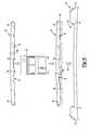
- FIG. 1is a schematic cross-sectional view of an emblem assembly having a planar configuration and including a first element and a second element;
- FIG. 2is a schematic cross-sectional view of the emblem assembly of FIG. 1 along section line 2 - 2 ;
- FIG. 3is a schematic cross-sectional view of a portion of the emblem assembly of FIG. 1 ;
- FIG. 4is a schematic cross-sectional view of a portion of another embodiment of the emblem assembly of FIG. 1 ;
- FIG. 5is a schematic cross-sectional view of a portion of yet another embodiment of the emblem assembly of FIGS. 1 and 4 ;
- FIG. 6is a schematic illustration of a method of forming the emblem assemblies of FIGS. 1 , 4 , and 5 ;
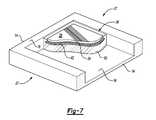
- FIG. 7is a schematic fragmentary perspective planar view of a corner configuration of the emblem assembly of FIG. 1 .
- an emblem assemblyis shown generally at 10 in FIG. 1 .
- the emblem assembly 10is configured for attachment to a vehicle 12 , such as an automotive vehicle.
- vehicle 12such as an automotive vehicle.
- the emblem assembly 10may also be useful for non-automotive vehicles such as, but not limited to, construction, rail, aviation, and marine vehicles.
- the emblem assembly 10includes a first element 14 configured for attachment to the vehicle 12 .
- the first element 14may be a carrier or bezel and may be configured for attachment to any location or component (not shown) of the vehicle 12 , such as, but not limited to, a front grille, rear liftgate, trunk lid, wheel cover, side panel, trim panel, and/or steering wheel.
- the first element 14may be attached to the vehicle 12 via any suitable method or attachment device, e.g., screws, tape, or a snap-fit. Therefore, the first element 14 may be formed from any suitable material and selected according to an expected operating environment of the vehicle 12 .
- the first element 14may be formed from metal, plastic, and combinations thereof.
- the first element 14may be coated for aesthetics and/or protection.
- the first element 14may be formed from chrome-plated plastic, such as acrylonitrile butadiene styrene (ABS).
- the first element 14has a first surface 16 and a second surface 18 recessed from the first surface 16 . That is, the second surface 18 may extend from the first surface 16 and define a recession or cavity 20 ( FIG. 6 ) within the first element 14 .
- the second surface 18may be substantially U-shaped.
- a portion of the first surface 16may be visible to a potential occupant or operator of the vehicle 12 when viewed from a direction of arrow 22 ( FIG. 1 ).
- the second surface 18may be substantially hidden by another component of the emblem assembly 10 , as set forth in more detail below.
- the emblem assembly 10also includes a second element 24 , as shown in FIG. 1 .
- the second element 24is configured for attachment to the first element 14 and may be generally sized and shaped to fit within the cavity 20 ( FIG. 6 ) defined by the second surface 18 of the first element 14 .
- the second element 24may be a lens configured for attachment to the aforementioned bezel, i.e., the first element 14 .
- comparatively more of the second element 24may be visible to a potential occupant or operator of the vehicle 12 than the first element 14 when viewed from the direction of arrow 22 . Therefore, the second element 24 may have a shape easily-recognizable as associated with a specific vehicle brand and/or manufacturer.
- the second element 24may have a square shape, a bowtie shape, a pointed shape, and/or may include a circular crest shape or a combination of letters.
- the second element 24may have a shape that is the same or different than the shape of the first element 14 .
- the second element 24has a third surface 26 and a fourth surface 28 spaced apart from the third surface 26 .
- the third surface 26may define a plurality of grooves 30 and/or voids 32 configured for reducing a weight of the second element 24 and/or enhancing attachment between the first element 14 and the second element 24 .
- the third surface 26may be hidden from view upon attachment of the emblem assembly 10 to the vehicle 12 when viewed from a direction of arrow 22 .
- the fourth surface 28may be visible to a potential occupant or operator of the vehicle 12 upon attachment of the emblem assembly 10 to the vehicle 12 when viewed from the direction of arrow 22 .
- the second element 24also has a fifth surface 34 extending between the third surface 26 and the fourth surface 28 .
- the fifth surface 34is spaced apart from the second surface 18 to define a channel 36 therebetween. That is, when the second element 24 is attached to the first element 14 , as set forth in more detail below, the second surface 18 is disposed adjacent the fifth surface 34 , and the channel 36 is defined therebetween.
- the channel 36may have a width 38 of from about 0.3 mm to about 0.7 mm, e.g., about 0.5 mm, so as to define a minimal gap between the first element 14 and the second element 24 .
- the fifth surface 34may also be substantially hidden from a vehicle occupant or operator when the first element 14 is attached to the second element 24 .
- the fifth surface 34 and at least one of the third surface 26 and the fourth surface 28may define an angle 40 therebetween of less than or equal to 90°. That is, a portion of the second element 24 may be tapered. Alternatively, although not shown, the third surface 26 and the fourth surface 28 may be substantially perpendicular to the fifth surface 34 .
- the second element 24may be formed from any suitable material.
- the second element 24may be formed from plastic, such as acrylic, metal, such as aluminum, and combinations thereof.
- the second element 24may be translucent, and may be tinted to a specific color, e.g., gold or red. In one variation, the second element 24 is transparent.
- the emblem assembly 10 of FIG. 1also includes a coating 42 disposed on the third surface 26 .
- the coating 42is not visible in FIG. 1 .
- the coating 42is disposed on the third surface 26 of FIG. 1 , as best shown in FIGS. 2 and 3 .
- the coating 42may be a layer capable of imparting enhanced aesthetics to the second element 24 and the emblem assembly 10 .
- the coating 42may include aluminum to impart a sheen or metallic appearance to the second element 24 .
- the coating 42may be deposited on the third surface 26 via any suitable process. More specifically, in one embodiment, the coating 42 may be a vacuum metalized coating. That is, the coating 42 may be deposited onto the third surface 26 of the second element 24 via vacuum metallization. As used herein, the terminology “vacuum metallization” refers to a physical vapor deposition process capable of depositing a thin aluminum layer, i.e., the coating 42 , onto a plastic component, e.g., the second element 24 . The coating 42 may have a thickness 44 ( FIG. 2 ) of from about 0.01 ⁇ m to about 0.2 ⁇ m.
- the thickness 44 of the coating 42may not substantially vary along the third surface 26 , and the coating 42 may be disposed along the entire third surface 26 , e.g., along any grooves 30 ( FIG. 1 ) and/or voids 32 ( FIG. 1 ) defined by the third surface 26 .
- the coating 42may be visible through the fourth surface 28 when viewed from the direction of arrow 22 ( FIG. 1 ). Therefore, to maximize the perceived quality of the vehicle 12 , the coating 42 may be substantially free from degradation, such as, but not limited to, corrosion, delamination, chipping, tears, uneven thickness 44 , uneven sheen or gloss, and combinations thereof.
- the coating 42may not extend along the fifth surface 34 . That is, the coating 42 may have a boundary 46 that terminates at an intersection of the third surface 26 and the fifth surface 34 . In one variation, as shown in FIG. 3 , the fifth surface 34 abuts the third surface 26 to form a corner 48 . Therefore, the coating 42 may be disposed solely along the third surface 26 so as not to wrap around the corner 48 ( FIG. 3 ) of the second element 24 .
- the emblem assembly 10further includes a molded resin 50 disposed adjacent and in fixed contact with each of the fifth surface 34 and the coating 42 ( FIG. 2 ) so as to contiguously encapsulate the coating 42 and at least a portion of the fifth surface 34 .
- the molded resin 50may abut the second surface 18 and wrap around the corner 48 ( FIG. 3 ) of the second element 24 to thereby act as a barrier to environmental contaminants and/or fluids. Therefore, as best shown in FIG. 3 , the molded resin 50 also contacts the coating 42 , e.g., at the boundary 46 of the coating 42 , and fills at least a portion of the channel 36 .
- the molded resin 50may encapsulate or envelop the coating 42 and at least a portion of the fifth surface 34 from the environment exterior to the vehicle 12 . In this variation, therefore, the molded resin 50 may not be visible when viewed from a direction of arrow 22 in FIG. 1 .
- the molded resin 50may substantially fill the channel 36 . That is, the molded resin 50 may have an edge 52 ( FIG. 5 ) that is substantially flush with the fourth surface 28 . Therefore, in this variation, the molded resin 50 may be visible when viewed from a direction of arrow 22 in FIG. 1 .
- the molded resin 50is disposed in fixed contact with each of the fifth surface 34 and the coating 42 ( FIG. 2 ). That is, the molded resin 50 is molded in place onto each of the fifth surface 34 and the coating 42 so as to contiguously encapsulate the coating 42 and at least a portion of the fifth surface 34 . As such, the molded resin 50 is not re-positionable, but is rather disposed in fixed contact with each of the fifth surface 34 and the coating 42 . In one example, the molded resin 50 may be low-pressure molded onto the second element 24 so as to wrap around the corner 48 ( FIG. 3 ) to thereby contact each of the coating 42 and the fifth surface 34 . That is, the molded resin 50 is disposed adjacent and in fixed contact with each of the fifth surface 34 and the coating 42 to thereby wrap around the corner 48 and fill at least a portion of the channel 36 .
- the molded resin 50is bondable to the first element 14 .
- the molded resin 50may adhere the second surface 18 to the coating 42 so that the second element 24 is attached to the first element 14 .
- the molded resin 50may be impermeable to environmental contaminants, e.g., dirt, rain, snow, and cleaning agents encountered during operation of the vehicle 12 .
- the molded resin 50may have a thickness 54 ( FIG. 2 ) of from about 0.2 mm to about 0.8 mm.
- the molded resin 50may have a thickness 54 of about 0.5 mm so as to contact and contiguously encapsulate each of the coating 42 and at least a portion of the fifth surface 34 .
- the molded resin 50may include a cured pressure-moldable thermoplastic resin having a tensile strength of from about 400 psi to about 500 psi, e.g., about 435 psi when measured in accordance with test method ASTM D638-10. That is, the molded resin 50 may include a resin characterized as “low-pressure moldable”. As used herein, the terminology “low-pressure moldable” refers to a resin that is injection moldable at a pressure of from about 75 psi to about 175 psi. For example, the molded resin 50 may be suitable for use in a low-pressure molding apparatus (shown generally at 60 in FIG. 6 ). The molded resin 50 when cured has a Shore A hardness of about 80.
- the molded resin 50may have an elongation at break of at least 500% when measured in accordance with test method ASTM D-3759. That is, the molded resin 50 may stretch within the channel 36 . Therefore, as best shown in FIG. 1 , the fourth surface 28 may be substantially flush with the first surface 16 . That is, the second element 24 may not protrude from the first element 14 , but rather the fourth surface 28 of the second element 24 may be coplanar with the first surface 16 of the first element 14 . Further, as shown in FIG. 7 , the second element 24 may be disposed within a periphery 27 of the first element 14 .
- the molded resin 50may be polyamide-based, polyester-based, polyolefin-based, or polyimide-based.
- the molded resin 50may also include additives such as, but not limited to, flow aids, colorants, catalysts, cross-linking agents, tackifying resins, waxes, plasticizers, stabilizers, flame retardants, fillers, and combinations thereof
- additivessuch as, but not limited to, flow aids, colorants, catalysts, cross-linking agents, tackifying resins, waxes, plasticizers, stabilizers, flame retardants, fillers, and combinations thereof
- Bostik® LPM 915commercially available from Lighthouse Molding, Inc. of Sterling Heights, Mich.
- the emblem assembly 10may further include an adhesive 56 sandwiched between and disposed in contact with each of the molded resin 50 and the second surface 18 to thereby bond the second element 24 to the first element 14 . That is, the adhesive 56 may adhere the molded resin 50 to the second surface 18 so that the second element 24 is attached to the first element 14 .
- the adhesive 56may also be impermeable to environmental contaminants, e.g., dirt, rain, snow, and cleaning agents encountered during operation of the vehicle 12 .
- the adhesive 56may have a thickness 58 ( FIG. 5 ) of from about 0.2 mm to about 0.8 mm.
- the adhesive 56may be a positionable tape and may have a thickness 58 of about 0.3 mm so as to contact each of the second surface 18 and the molded resin 50 within the channel 36 . That is, the adhesive 56 may be positioned, and re-positioned if necessary, to contact at least a portion of, for example, the molded resin 50 . Further, the adhesive 56 may exhibit compressibility and may have an elongation at break of at least 100% when measured in accordance with test method ASTM D-3759. That is, the adhesive 56 may stretch and compress within the channel 36 so that the second element 24 does not protrude from the first element 14 .
- the adhesive 56may include acrylic and foam and may have a flexible core.
- the adhesive 56may include a viscoelastic foam core and acrylic adhesive, and may be double-sided. That is, the acrylic adhesive may be disposed on two opposing surfaces of the viscoelastic foam core.
- a specific example of a suitable adhesive 56is 3MTM Acrylic Foam Tape 5344, commercially available from 3M of St. Paul, Minn.
- the emblem assembly 10includes the first element 14 , the transparent second element 24 , the coating 42 disposed on the third surface 26 , wherein the coating 42 includes vacuum metalized aluminum and is substantially free from degradation, the molded resin 50 disposed adjacent and in fixed contact with each of the fifth surface 34 and the coating 42 so as to contiguously encapsulate the coating 42 and at least a portion of the fifth surface 34 to thereby wrap around the corner 48 and fill at least a portion of the channel 36 , and the adhesive 56 sandwiched between and disposed in contact with each of the molded resin 50 and the second surface 18 to thereby bond the second element 24 to the first element 14 .
- the coating 42includes vacuum metalized aluminum and is substantially free from degradation
- the molded resin 50disposed adjacent and in fixed contact with each of the fifth surface 34 and the coating 42 so as to contiguously encapsulate the coating 42 and at least a portion of the fifth surface 34 to thereby wrap around the corner 48 and fill at least a portion of the channel 36
- the adhesive 56sandwiched between and disposed
- the molded resin 50provides the emblem assembly 10 with minimized degradation over an operating life of the vehicle 12 .
- the coating 42is substantially free from corrosion after continued exposure to cleaning solutions and vehicle operating environments.
- the molded resin 50sufficiently seals the channel 36 to prevent ingress of fluids and/or contaminants to thereby minimize contact between such fluids and/or contaminants and the coating 42 .
- a method of forming the emblem assembly 10is also disclosed and described with reference to FIGS. 2 and 6 .
- the methodincludes depositing the coating 42 ( FIG. 2 ) on the second element 24 , whereby the coating 42 is disposed on the third surface 26 , as best shown in FIG. 2 .
- the coating 42may be deposited onto the third surface 26 of the second element 24 via vacuum metallization.
- the coating 42may be deposited via a physical vapor deposition process capable of depositing the coating 42 onto the second element 24 .
- the deposited coating 42may have a thickness 44 ( FIG. 2 ) of from about 0.01 ⁇ m to about 0.2 ⁇ m.
- the thickness 44 of the coating 42may not substantially vary along the third surface 26 , and the coating 42 may be disposed along the entire third surface 26 , e.g., along any grooves 30 ( FIG. 1 ) and/or voids 32 ( FIG. 1 ) defined by the third surface 26 .
- the methodalso includes, after depositing the coating 42 ( FIG. 2 ), forming the molded resin 50 on the second element 24 whereby the molded resin 50 is disposed adjacent and in fixed contact with each of the fifth surface 34 and the coating 42 so as to contiguously encapsulate the coating 42 and at least a portion of the fifth surface 34 , as set forth above. That is, the molded resin 50 may envelop the coating 42 and the fifth surface 34 . More specifically, forming may include curing the molded resin 50 on the second element 24 at a pressure of from about 75 psi to about 175 psi.
- the molded resin 50may be low-pressure molded onto the coating 42 and at least a portion of the fifth surface 34 of the second element 24 .
- formingmay include disposing the molded resin 50 on an entire length of the fifth surface 34 , as shown in FIG. 4 , or may include disposing the molded resin 50 on only a portion of the fifth surface 34 , as shown in FIG. 3 .
- Formingmay include curing the molded resin 50 in any suitable device or system, such as a low-pressure injection molding apparatus shown generally at 60 in FIG. 6 .
- formingmay include inserting the second element 24 , including the coating 42 deposited thereon, into the low-pressure injection molding apparatus 60 for contact with a resin feedstock (not shown). More specifically, the second element 24 may be disposed within a cavity of a mold (not shown), and the resin feedstock may be injected into the cavity.
- the pressure of the cavityi.e., the “low-pressure” of the low-pressure injection molding apparatus 60
- the pressure of the cavityi.e., the “low-pressure” of the low-pressure injection molding apparatus 60
- the pressure of the cavityis maintained at from about 75 psi to about 175 psi to thereby cure the molded resin 50 in fixed contact with each of the coating 42 and at least a portion of the fifth surface 34 .
- a cycle time for forming the molded resin 50 on the second element 24may range from about 5 seconds to about 15 seconds, e.g., about 10 seconds. As such, forming the molded resin 50 is economical and does not detrimentally increase manufacturing cycle times for the emblem assembly 10 and/or the vehicle 12 . Curing the molded resin 50 in the low-pressure injection molding apparatus 60 also does not detrimentally affect heat-sensitive resin feedstocks.
- the methodfurther includes bonding the molded resin 50 to the first element 14 to thereby form the emblem assembly 10 ( FIGS. 1 , 4 , and 5 ). That is, the molded resin 50 may be attached to the first element 14 . More specifically, bonding may include adhering the molded resin 50 to the first element 14 . For example, adhering may include sandwiching the adhesive 56 ( FIG. 5 ) between each of the molded resin 50 and the second surface 18 to thereby attach the second element 24 to the first element 14 .
- bondingmay include inserting the second element 24 into the first element 14 , e.g., in the direction of arrow 62 in FIG. 6 , whereby the molded resin 50 contacts the second surface 18 to thereby form the emblem assembly 10 ( FIGS. 1 , 4 , and 5 ).
- the second element 24 including the molded resin 50 disposed on the coating 42may be press fit into the cavity 20 ( FIG. 6 ) defined by the second surface 18 of the first element 14 so that the interaction of the first element 14 and the second element 24 compresses the molded resin 50 therebetween.
- insertingmay include filling at least a portion of the channel 36 ( FIGS. 1 , 4 , and 5 ) with the molded resin 50 . That is, referring to FIG. 3 , upon inserting the second element 24 into the first element 14 , the molded resin 50 may contact the second surface 18 and extend from the second surface 18 into the channel 36 to thereby attach, e.g., adhere, the second element 24 to the first element 14 . Consequently, inserting may include sealing the channel 36 , and therefore each of the coating 42 and the fifth surface 34 , from environmental contaminants to prevent ingress of contaminants and/or fluids into the channel 36 .
- bonding the molded resin 50 to the first element 14minimizes fluid and/or contaminant contact with each of the coating 42 and the fifth surface 34 .
- the methodallows for economical and efficient formation of the emblem assembly 10 , and the emblem assembly 10 contributes to an increased perceived quality of the vehicle 12 .
Landscapes
- Engineering & Computer Science (AREA)
- Mechanical Engineering (AREA)
- Vehicle Waterproofing, Decoration, And Sanitation Devices (AREA)
- Vehicle Interior And Exterior Ornaments, Soundproofing, And Insulation (AREA)
- Body Structure For Vehicles (AREA)
- Application Of Or Painting With Fluid Materials (AREA)
Abstract
Description
Claims (20)
Priority Applications (4)
| Application Number | Priority Date | Filing Date | Title |
|---|---|---|---|
| US12/890,798US8617670B2 (en) | 2010-09-27 | 2010-09-27 | Emblem assembly and method of forming same |
| DE102011113770.3ADE102011113770B4 (en) | 2010-09-27 | 2011-09-19 | Emblem assembly and method of forming same |
| BRPI1107092-7ABRPI1107092A2 (en) | 2010-09-27 | 2011-09-27 | emblem set and method to form an emblem set |
| CN201110295414.8ACN102529833B (en) | 2010-09-27 | 2011-09-27 | Logo assembly and forming method thereof |
Applications Claiming Priority (1)
| Application Number | Priority Date | Filing Date | Title |
|---|---|---|---|
| US12/890,798US8617670B2 (en) | 2010-09-27 | 2010-09-27 | Emblem assembly and method of forming same |
Publications (2)
| Publication Number | Publication Date |
|---|---|
| US20120076958A1 US20120076958A1 (en) | 2012-03-29 |
| US8617670B2true US8617670B2 (en) | 2013-12-31 |
Family
ID=45804937
Family Applications (1)
| Application Number | Title | Priority Date | Filing Date |
|---|---|---|---|
| US12/890,798ActiveUS8617670B2 (en) | 2010-09-27 | 2010-09-27 | Emblem assembly and method of forming same |
Country Status (4)
| Country | Link |
|---|---|
| US (1) | US8617670B2 (en) |
| CN (1) | CN102529833B (en) |
| BR (1) | BRPI1107092A2 (en) |
| DE (1) | DE102011113770B4 (en) |
Cited By (1)
| Publication number | Priority date | Publication date | Assignee | Title |
|---|---|---|---|---|
| US11383412B2 (en)* | 2017-05-15 | 2022-07-12 | Marelli Automotive Lighting France | Process for manufacturing a shell comprising a decorative film |
Families Citing this family (7)
| Publication number | Priority date | Publication date | Assignee | Title |
|---|---|---|---|---|
| EP2687412B1 (en)* | 2012-07-17 | 2016-03-23 | Dalphi Metal España, S.A. | Cover for a gas bag module, a bag module with said cover, steering wheel and method of manufacturing said cover |
| KR102331876B1 (en)* | 2014-07-10 | 2021-11-29 | 코닝 인코포레이티드 | Cold formed glass applique |
| US9834155B2 (en)* | 2016-03-09 | 2017-12-05 | GM Global Technology Operations LLC | Radar transparent vehicle emblem with multi-color, multi-dimensional A-surface |
| DE102016009227A1 (en)* | 2016-07-28 | 2018-02-01 | Audi Ag | Vehicle decorative part and method for its production |
| JP7101634B2 (en)* | 2019-03-29 | 2022-07-15 | 本田技研工業株式会社 | Resin molded product |
| JP7561570B2 (en)* | 2020-10-22 | 2024-10-04 | 株式会社ファルテック | Radar cover and manufacturing method thereof |
| CN113565843B (en)* | 2021-06-30 | 2023-04-18 | 上海华谷车业有限公司 | Method for improving part clearance of adhesive tape in gear mounting process |
Citations (35)
| Publication number | Priority date | Publication date | Assignee | Title |
|---|---|---|---|---|
| US4076789A (en) | 1976-04-12 | 1978-02-28 | General Motors Corporation | Method of forming an embossed and coated design on the surface of a formable plastic sheet |
| US4130623A (en) | 1976-04-12 | 1978-12-19 | General Motors Corporation | Method of embossing |
| US4292827A (en)* | 1978-05-08 | 1981-10-06 | The D. L. Auld Company | Method for making decorative emblems |
| EP0060721A1 (en) | 1981-03-16 | 1982-09-22 | The D.L.Auld Company | Decorative emblems and method for making same |
| US4481160A (en)* | 1979-12-17 | 1984-11-06 | The D. L. Auld Company | Manufacture of decorative emblems |
| US4556588A (en)* | 1982-08-25 | 1985-12-03 | The D. L. Auld Company | Decorative emblem useful in customizing an automobile and other surfaces |
| US4769100A (en) | 1986-09-22 | 1988-09-06 | General Motors Corporation | Method of applying carrier films prepainted with metallic paint to automobile body panels |
| US4824506A (en) | 1988-04-21 | 1989-04-25 | General Motors Corporation | Process for protecting thermoformed films |
| US4826713A (en)* | 1987-09-08 | 1989-05-02 | The Standard Products Company | Trim strip with three-dimensional markings |
| US4828637A (en) | 1986-07-02 | 1989-05-09 | General Motors Corporation | Method of applying painted carrier films to automobile body parts |
| US4838973A (en) | 1986-07-02 | 1989-06-13 | General Motors Corporation | Method of applying painted carrier films to automobile body parts |
| US4856857A (en)* | 1985-05-07 | 1989-08-15 | Dai Nippon Insatsu Kabushiki Kaisha | Transparent reflection-type |
| US4868030A (en) | 1986-07-02 | 1989-09-19 | General Motors Corporation | Article covered with painted carrier films |
| US4957802A (en) | 1986-07-02 | 1990-09-18 | General Motors Corporation | Article covered with painted carrier films |
| US4960558A (en) | 1988-08-17 | 1990-10-02 | General Motors Corporation | Process for thermoforming multihued laminate films |
| US4976896A (en) | 1988-08-17 | 1990-12-11 | General Motors Corporation | Process of making thermoformable laminate films and processes |
| US5021278A (en) | 1988-08-17 | 1991-06-04 | General Motors Corporation | Thermoformable multihued laminate films and processes |
| US5433980A (en)* | 1994-06-13 | 1995-07-18 | The Auld Company | Preserved portraits and photographs and method for making same |
| US5480688A (en)* | 1994-06-13 | 1996-01-02 | The Auld Company | Shaped flexible decorative articles and method for making same |
| DE9321214U1 (en) | 1992-12-17 | 1996-09-12 | Minnesota Mining And Mfg. Co., Saint Paul, Minn. | Decorative element |
| US5698276A (en)* | 1995-03-31 | 1997-12-16 | Ford Global Technologies, Inc. | Oval ornament having a locked-in urethane lens |
| US5795527A (en)* | 1994-04-29 | 1998-08-18 | Nissha Printing Co., Ltd. | Method of manufacturing decorated article using a transfer material |
| WO1999008870A1 (en) | 1997-08-18 | 1999-02-25 | Minnesota Mining And Manufacturing Company | Paint film assembly with masking film |
| US5933867A (en)* | 1996-05-31 | 1999-08-10 | The Auld Company | Promotional item having decorative emblem and method of making same |
| EP0942820A1 (en) | 1996-11-28 | 1999-09-22 | Minnesota Mining And Manufacturing Company | Method of preparing decorative articles |
| US6071621A (en)* | 1993-06-11 | 2000-06-06 | 3M Innovative Properties Company | Metallized film and decorative articles made therewith |
| US20020032250A1 (en) | 2000-07-05 | 2002-03-14 | Mitsubishi Rayon Co., Ltd. | Photocuring resin compositions, photocuring sheets and molded article using the same, and processes of production thereof |
| US6372341B1 (en)* | 1998-04-27 | 2002-04-16 | 3M Innovative Properties Company | Tampa-indicating article for reusable substrates |
| US20030008134A1 (en) | 1998-05-22 | 2003-01-09 | Patent Holding Company | Molding method and metal-covered component formed thereby |
| US6579397B1 (en) | 1987-03-27 | 2003-06-17 | Avery Dennison Corporation | Dry paint transfer process for making deep draw high DOI automotive body panels |
| US6682805B1 (en) | 1999-05-14 | 2004-01-27 | General Electric Company | Insert mold decorating film for thermoplastic resin |
| US6835348B2 (en) | 2000-01-13 | 2004-12-28 | Mogami Denki Corporation | Method and device for producing open type polymide moldings, and base material for reflective bodies in lighting equipment |
| US6863854B2 (en) | 2000-02-25 | 2005-03-08 | General Electric | Insert mold decorating film for thermoplastic resin and methods for making |
| US7390454B2 (en) | 2004-08-19 | 2008-06-24 | General Motors Corporation | Thermoforming process for producing class “A” finish, high gloss automotive exterior parts |
| DE102007041347A1 (en) | 2007-08-30 | 2009-03-05 | Linden Gmbh & Co. Kg | Emblem with colored and shiny silver surfaces |
Family Cites Families (2)
| Publication number | Priority date | Publication date | Assignee | Title |
|---|---|---|---|---|
| US4100010A (en)* | 1974-06-12 | 1978-07-11 | The D. L. Auld Company | Method for making decorative emblems |
| EP1839952B1 (en)* | 2006-03-28 | 2011-10-19 | Autoliv Development AB | Emblem of automobile part and method of manufacturing the same |
- 2010
- 2010-09-27USUS12/890,798patent/US8617670B2/enactiveActive
- 2011
- 2011-09-19DEDE102011113770.3Apatent/DE102011113770B4/enactiveActive
- 2011-09-27CNCN201110295414.8Apatent/CN102529833B/enactiveActive
- 2011-09-27BRBRPI1107092-7Apatent/BRPI1107092A2/ennot_activeIP Right Cessation
Patent Citations (39)
| Publication number | Priority date | Publication date | Assignee | Title |
|---|---|---|---|---|
| US4130623A (en) | 1976-04-12 | 1978-12-19 | General Motors Corporation | Method of embossing |
| US4076789A (en) | 1976-04-12 | 1978-02-28 | General Motors Corporation | Method of forming an embossed and coated design on the surface of a formable plastic sheet |
| US4292827A (en)* | 1978-05-08 | 1981-10-06 | The D. L. Auld Company | Method for making decorative emblems |
| US4481160A (en)* | 1979-12-17 | 1984-11-06 | The D. L. Auld Company | Manufacture of decorative emblems |
| EP0060721A1 (en) | 1981-03-16 | 1982-09-22 | The D.L.Auld Company | Decorative emblems and method for making same |
| US4556588A (en)* | 1982-08-25 | 1985-12-03 | The D. L. Auld Company | Decorative emblem useful in customizing an automobile and other surfaces |
| US4856857A (en)* | 1985-05-07 | 1989-08-15 | Dai Nippon Insatsu Kabushiki Kaisha | Transparent reflection-type |
| US4838973A (en) | 1986-07-02 | 1989-06-13 | General Motors Corporation | Method of applying painted carrier films to automobile body parts |
| US4828637A (en) | 1986-07-02 | 1989-05-09 | General Motors Corporation | Method of applying painted carrier films to automobile body parts |
| US4868030A (en) | 1986-07-02 | 1989-09-19 | General Motors Corporation | Article covered with painted carrier films |
| US4957802A (en) | 1986-07-02 | 1990-09-18 | General Motors Corporation | Article covered with painted carrier films |
| US4769100A (en) | 1986-09-22 | 1988-09-06 | General Motors Corporation | Method of applying carrier films prepainted with metallic paint to automobile body panels |
| US6579397B1 (en) | 1987-03-27 | 2003-06-17 | Avery Dennison Corporation | Dry paint transfer process for making deep draw high DOI automotive body panels |
| US4826713A (en)* | 1987-09-08 | 1989-05-02 | The Standard Products Company | Trim strip with three-dimensional markings |
| US4824506A (en) | 1988-04-21 | 1989-04-25 | General Motors Corporation | Process for protecting thermoformed films |
| US4960558A (en) | 1988-08-17 | 1990-10-02 | General Motors Corporation | Process for thermoforming multihued laminate films |
| US5021278A (en) | 1988-08-17 | 1991-06-04 | General Motors Corporation | Thermoformable multihued laminate films and processes |
| US4976896A (en) | 1988-08-17 | 1990-12-11 | General Motors Corporation | Process of making thermoformable laminate films and processes |
| DE9321214U1 (en) | 1992-12-17 | 1996-09-12 | Minnesota Mining And Mfg. Co., Saint Paul, Minn. | Decorative element |
| US6641921B2 (en)* | 1993-06-11 | 2003-11-04 | 3M Innovative Properties Company | Metallized film and decorative articles made therewith |
| US6071621A (en)* | 1993-06-11 | 2000-06-06 | 3M Innovative Properties Company | Metallized film and decorative articles made therewith |
| US5795527A (en)* | 1994-04-29 | 1998-08-18 | Nissha Printing Co., Ltd. | Method of manufacturing decorated article using a transfer material |
| US5480688A (en)* | 1994-06-13 | 1996-01-02 | The Auld Company | Shaped flexible decorative articles and method for making same |
| US5433980A (en)* | 1994-06-13 | 1995-07-18 | The Auld Company | Preserved portraits and photographs and method for making same |
| US5698276A (en)* | 1995-03-31 | 1997-12-16 | Ford Global Technologies, Inc. | Oval ornament having a locked-in urethane lens |
| US5933867A (en)* | 1996-05-31 | 1999-08-10 | The Auld Company | Promotional item having decorative emblem and method of making same |
| EP0942820A1 (en) | 1996-11-28 | 1999-09-22 | Minnesota Mining And Manufacturing Company | Method of preparing decorative articles |
| WO1999008870A1 (en) | 1997-08-18 | 1999-02-25 | Minnesota Mining And Manufacturing Company | Paint film assembly with masking film |
| US6372341B1 (en)* | 1998-04-27 | 2002-04-16 | 3M Innovative Properties Company | Tampa-indicating article for reusable substrates |
| US6818305B2 (en)* | 1998-05-22 | 2004-11-16 | Patent Holding Company | Molding method and metal-covered component formed thereby |
| US20030008134A1 (en) | 1998-05-22 | 2003-01-09 | Patent Holding Company | Molding method and metal-covered component formed thereby |
| US6682805B1 (en) | 1999-05-14 | 2004-01-27 | General Electric Company | Insert mold decorating film for thermoplastic resin |
| US6835348B2 (en) | 2000-01-13 | 2004-12-28 | Mogami Denki Corporation | Method and device for producing open type polymide moldings, and base material for reflective bodies in lighting equipment |
| US6863854B2 (en) | 2000-02-25 | 2005-03-08 | General Electric | Insert mold decorating film for thermoplastic resin and methods for making |
| US6646022B2 (en)* | 2000-07-05 | 2003-11-11 | Mitsubishi Rayon Co., Ltd. | Photocuring resin compositions, photocuring sheets and molded article using the same, and processes of production thereof |
| US20020032250A1 (en) | 2000-07-05 | 2002-03-14 | Mitsubishi Rayon Co., Ltd. | Photocuring resin compositions, photocuring sheets and molded article using the same, and processes of production thereof |
| US7390454B2 (en) | 2004-08-19 | 2008-06-24 | General Motors Corporation | Thermoforming process for producing class “A” finish, high gloss automotive exterior parts |
| US7645416B2 (en) | 2004-08-19 | 2010-01-12 | Gm Global Technology Operations, Inc. | Thermoforming process for producing class “A” finish, high gloss automotive exterior parts |
| DE102007041347A1 (en) | 2007-08-30 | 2009-03-05 | Linden Gmbh & Co. Kg | Emblem with colored and shiny silver surfaces |
Non-Patent Citations (3)
| Title |
|---|
| U.S. Appl. No. 13/303,729, filed Nov. 23, 2011, Catherine A. Ostrander, Kitty L. Gong, Charles K. Buehler, Chris A. Oberlitner. |
| U.S. Appl. No. 13/343,763, filed Jan. 5, 2012, Catherine A. Ostrander, Kitty L. Gong, Charles K. Buehler, Chris A. Oberlitner. |
| U.S. Appl. No. 13/361,173, filed Jan. 30, 2012, Catherine A. Ostrander, Joel Colombo, Mary K. Gusie, Kitty L. Gong, Charles K. Buehler, Michael P. Balogh. |
Cited By (1)
| Publication number | Priority date | Publication date | Assignee | Title |
|---|---|---|---|---|
| US11383412B2 (en)* | 2017-05-15 | 2022-07-12 | Marelli Automotive Lighting France | Process for manufacturing a shell comprising a decorative film |
Also Published As
| Publication number | Publication date |
|---|---|
| BRPI1107092A2 (en) | 2013-01-29 |
| CN102529833A (en) | 2012-07-04 |
| DE102011113770B4 (en) | 2018-12-13 |
| CN102529833B (en) | 2016-04-20 |
| DE102011113770A1 (en) | 2012-03-29 |
| US20120076958A1 (en) | 2012-03-29 |
Similar Documents
| Publication | Publication Date | Title |
|---|---|---|
| US8617670B2 (en) | Emblem assembly and method of forming same | |
| US11718244B2 (en) | Trim part | |
| US20100080939A1 (en) | Emblem having colored and silvery surfaces | |
| US6168742B1 (en) | Method of insert molding auto and truck bumper, rocker panel and chin spoiler parts | |
| US20220266766A1 (en) | Fixed Window Assembly For A Vehicle And Method Of Manufacturing Same | |
| JP6274111B2 (en) | Vehicle window plate with frame and method of assembling vehicle window plate with frame | |
| US20060145496A1 (en) | Applique for a-pillar area of vehicle | |
| WO2014054757A1 (en) | Belt molding for vehicle | |
| US6959948B2 (en) | Gimp with a concealed slip zone | |
| WO2007000886A1 (en) | Method for producing window glass with decoration member and window glass with decoration member | |
| US8372493B2 (en) | Emblem assembly and method of forming same | |
| US5350608A (en) | Decorative trim with one-piece plastic cover | |
| US8617671B2 (en) | Emblem assembly and method of forming same | |
| JP6065338B2 (en) | Vehicle window plate with frame and method of assembling vehicle window plate with frame | |
| JPH02175419A (en) | Manufacture of hard plate insert module assembly window | |
| CN216968460U (en) | Decorative panel for motor vehicle and motor vehicle including the same | |
| CN114423608A (en) | Visible parts with layer structure for handling parts or trim strips with improved protection due to protective lacquer coating | |
| CN2837135Y (en) | Inlaid glass envelope assembly | |
| US10279766B2 (en) | Low stress attachment for high gloss weatherable polycarbonate decorative applications | |
| JP2009083742A (en) | Insert panel embedded weatherstrip and manufacturing method thereof | |
| JP4225105B2 (en) | Automotive beltline mall | |
| US20080197657A1 (en) | Upper windshield quiet clip | |
| KR100412620B1 (en) | garnish assembly for a vehicle | |
| US20180222300A1 (en) | Pane assembly, in particular pane assembly for vehicle body | |
| JPH042787A (en) | Production of part for automobile |
Legal Events
| Date | Code | Title | Description |
|---|---|---|---|
| AS | Assignment | Owner name:GM GLOBAL TECHNOLOGY OPERATIONS, INC., MICHIGAN Free format text:ASSIGNMENT OF ASSIGNORS INTEREST;ASSIGNOR:SZYMBERSKI, MICHAEL A.;REEL/FRAME:025045/0261 Effective date:20100921 | |
| AS | Assignment | Owner name:WILMINGTON TRUST COMPANY, DELAWARE Free format text:SECURITY AGREEMENT;ASSIGNOR:GM GLOBAL TECHNOLOGY OPERATIONS, INC.;REEL/FRAME:025324/0658 Effective date:20101027 | |
| AS | Assignment | Owner name:GM GLOBAL TECHNOLOGY OPERATIONS LLC, MICHIGAN Free format text:CHANGE OF NAME;ASSIGNOR:GM GLOBAL TECHNOLOGY OPERATIONS, INC.;REEL/FRAME:025780/0482 Effective date:20101202 | |
| FEPP | Fee payment procedure | Free format text:PAYOR NUMBER ASSIGNED (ORIGINAL EVENT CODE: ASPN); ENTITY STATUS OF PATENT OWNER: LARGE ENTITY | |
| STCF | Information on status: patent grant | Free format text:PATENTED CASE | |
| AS | Assignment | Owner name:GM GLOBAL TECHNOLOGY OPERATIONS LLC, MICHIGAN Free format text:RELEASE BY SECURED PARTY;ASSIGNOR:WILMINGTON TRUST COMPANY;REEL/FRAME:034287/0159 Effective date:20141017 | |
| FPAY | Fee payment | Year of fee payment:4 | |
| MAFP | Maintenance fee payment | Free format text:PAYMENT OF MAINTENANCE FEE, 8TH YEAR, LARGE ENTITY (ORIGINAL EVENT CODE: M1552); ENTITY STATUS OF PATENT OWNER: LARGE ENTITY Year of fee payment:8 | |
| FEPP | Fee payment procedure | Free format text:MAINTENANCE FEE REMINDER MAILED (ORIGINAL EVENT CODE: REM.); ENTITY STATUS OF PATENT OWNER: LARGE ENTITY |