US8617399B2 - Dynamic filtration system and associated methods - Google Patents
Dynamic filtration system and associated methodsDownload PDFInfo
- Publication number
- US8617399B2 US8617399B2US13/584,705US201213584705AUS8617399B2US 8617399 B2US8617399 B2US 8617399B2US 201213584705 AUS201213584705 AUS 201213584705AUS 8617399 B2US8617399 B2US 8617399B2
- Authority
- US
- United States
- Prior art keywords
- filter device
- filter
- magnetic
- fluid
- body portion
- Prior art date
- Legal status (The legal status is an assumption and is not a legal conclusion. Google has not performed a legal analysis and makes no representation as to the accuracy of the status listed.)
- Expired - Fee Related
Links
- 238000001914filtrationMethods0.000titleclaimsabstractdescription78
- 238000000034methodMethods0.000titleclaimsabstractdescription23
- 230000005291magnetic effectEffects0.000claimsabstractdescription93
- 239000000126substanceSubstances0.000claimsabstractdescription53
- 239000011554ferrofluidSubstances0.000claimsabstractdescription42
- 239000012530fluidSubstances0.000claimsdescription94
- XEEYBQQBJWHFJM-UHFFFAOYSA-NIronChemical compound[Fe]XEEYBQQBJWHFJM-UHFFFAOYSA-N0.000claimsdescription32
- 229910052742ironInorganic materials0.000claimsdescription16
- NINIDFKCEFEMDL-UHFFFAOYSA-NSulfurChemical compound[S]NINIDFKCEFEMDL-UHFFFAOYSA-N0.000claimsdescription12
- 229910052717sulfurInorganic materials0.000claimsdescription12
- 239000011593sulfurSubstances0.000claimsdescription12
- RWSOTUBLDIXVET-UHFFFAOYSA-NDihydrogen sulfideChemical compoundSRWSOTUBLDIXVET-UHFFFAOYSA-N0.000claimsdescription5
- 230000008859changeEffects0.000claimsdescription5
- 230000005672electromagnetic fieldEffects0.000claimsdescription5
- 239000002907paramagnetic materialSubstances0.000claimsdescription5
- 239000000758substrateSubstances0.000claimsdescription4
- MBMLMWLHJBBADN-UHFFFAOYSA-NFerrous sulfideChemical compound[Fe]=SMBMLMWLHJBBADN-UHFFFAOYSA-N0.000claimsdescription3
- 238000006243chemical reactionMethods0.000claimsdescription3
- 239000003302ferromagnetic materialSubstances0.000claimsdescription3
- ZOXJGFHDIHLPTG-UHFFFAOYSA-NBoronChemical compound[B]ZOXJGFHDIHLPTG-UHFFFAOYSA-N0.000claimsdescription2
- 229910021536ZeoliteInorganic materials0.000claimsdescription2
- 229910052796boronInorganic materials0.000claimsdescription2
- HNPSIPDUKPIQMN-UHFFFAOYSA-Ndioxosilane;oxo(oxoalumanyloxy)alumaneChemical compoundO=[Si]=O.O=[Al]O[Al]=OHNPSIPDUKPIQMN-UHFFFAOYSA-N0.000claimsdescription2
- 230000008569processEffects0.000claimsdescription2
- 229910052596spinelInorganic materials0.000claimsdescription2
- 239000011029spinelSubstances0.000claimsdescription2
- 239000010457zeoliteSubstances0.000claimsdescription2
- 230000001939inductive effectEffects0.000claims1
- 230000003993interactionEffects0.000claims1
- 230000000704physical effectEffects0.000claims1
- 238000005516engineering processMethods0.000description25
- 238000001179sorption measurementMethods0.000description18
- 239000000463materialSubstances0.000description11
- RYGMFSIKBFXOCR-UHFFFAOYSA-NCopperChemical compound[Cu]RYGMFSIKBFXOCR-UHFFFAOYSA-N0.000description10
- 239000000356contaminantSubstances0.000description10
- 229910052802copperInorganic materials0.000description10
- 239000010949copperSubstances0.000description10
- 238000009826distributionMethods0.000description7
- 239000002245particleSubstances0.000description7
- VNWKTOKETHGBQD-UHFFFAOYSA-NmethaneChemical compoundCVNWKTOKETHGBQD-UHFFFAOYSA-N0.000description6
- OKTJSMMVPCPJKN-UHFFFAOYSA-NCarbonChemical compound[C]OKTJSMMVPCPJKN-UHFFFAOYSA-N0.000description5
- 230000008901benefitEffects0.000description5
- 239000013078crystalSubstances0.000description4
- LFQSCWFLJHTTHZ-UHFFFAOYSA-NEthanolChemical compoundCCOLFQSCWFLJHTTHZ-UHFFFAOYSA-N0.000description3
- 150000001875compoundsChemical class0.000description3
- 230000005294ferromagnetic effectEffects0.000description3
- 239000011521glassSubstances0.000description3
- 239000000696magnetic materialSubstances0.000description3
- 239000003345natural gasSubstances0.000description3
- XLYOFNOQVPJJNP-UHFFFAOYSA-NwaterSubstancesOXLYOFNOQVPJJNP-UHFFFAOYSA-N0.000description3
- PEDCQBHIVMGVHV-UHFFFAOYSA-NGlycerineChemical compoundOCC(O)COPEDCQBHIVMGVHV-UHFFFAOYSA-N0.000description2
- 239000007789gasSubstances0.000description2
- 229910021389grapheneInorganic materials0.000description2
- 229910000037hydrogen sulfideInorganic materials0.000description2
- 239000007788liquidSubstances0.000description2
- 239000011159matrix materialSubstances0.000description2
- -1plasmasSubstances0.000description2
- 239000004033plasticSubstances0.000description2
- 229920003023plasticPolymers0.000description2
- 239000002861polymer materialSubstances0.000description2
- 239000002244precipitateSubstances0.000description2
- 229910052582BNInorganic materials0.000description1
- PZNSFCLAULLKQX-UHFFFAOYSA-NBoron nitrideChemical compoundN#BPZNSFCLAULLKQX-UHFFFAOYSA-N0.000description1
- 239000004801Chlorinated PVCSubstances0.000description1
- 229910000640Fe alloyInorganic materials0.000description1
- 239000004813Perfluoroalkoxy alkaneSubstances0.000description1
- 239000004698PolyethyleneSubstances0.000description1
- 239000004743PolypropyleneSubstances0.000description1
- 238000004026adhesive bondingMethods0.000description1
- 230000005303antiferromagnetismEffects0.000description1
- 230000009286beneficial effectEffects0.000description1
- 125000002915carbonyl groupChemical group[*:2]C([*:1])=O0.000description1
- 239000003054catalystSubstances0.000description1
- 229910001567cementiteInorganic materials0.000description1
- 239000000919ceramicSubstances0.000description1
- 238000012512characterization methodMethods0.000description1
- 229920000457chlorinated polyvinyl chloridePolymers0.000description1
- 238000004891communicationMethods0.000description1
- 238000000748compression mouldingMethods0.000description1
- 239000004020conductorSubstances0.000description1
- 239000000470constituentSubstances0.000description1
- 238000001514detection methodMethods0.000description1
- 238000001125extrusionMethods0.000description1
- 230000005307ferromagnetismEffects0.000description1
- 239000000446fuelSubstances0.000description1
- 235000011187glycerolNutrition0.000description1
- 229910002804graphiteInorganic materials0.000description1
- 239000010439graphiteSubstances0.000description1
- 229910052736halogenInorganic materials0.000description1
- 150000002367halogensChemical class0.000description1
- 238000003306harvestingMethods0.000description1
- 238000010102injection blow mouldingMethods0.000description1
- 238000001746injection mouldingMethods0.000description1
- 238000005304joiningMethods0.000description1
- 230000005415magnetizationEffects0.000description1
- 238000004519manufacturing processMethods0.000description1
- 230000007246mechanismEffects0.000description1
- 239000012528membraneSubstances0.000description1
- 229910052751metalInorganic materials0.000description1
- 239000002184metalSubstances0.000description1
- 150000002739metalsChemical class0.000description1
- 238000012986modificationMethods0.000description1
- 230000004048modificationEffects0.000description1
- 230000005298paramagnetic effectEffects0.000description1
- 230000005408paramagnetismEffects0.000description1
- 229920011301perfluoro alkoxyl alkanePolymers0.000description1
- 210000002381plasmaAnatomy0.000description1
- 238000009428plumbingMethods0.000description1
- 229920000642polymerPolymers0.000description1
- 239000004810polytetrafluoroethyleneSubstances0.000description1
- 229920001343polytetrafluoroethylenePolymers0.000description1
- 239000004800polyvinyl chlorideSubstances0.000description1
- 229920000915polyvinyl chloridePolymers0.000description1
- 238000011045prefiltrationMethods0.000description1
- 230000004044responseEffects0.000description1
- 239000007787solidSubstances0.000description1
- 239000000243solutionSubstances0.000description1
- 238000003856thermoformingMethods0.000description1
- 239000002699waste materialSubstances0.000description1
- 238000003466weldingMethods0.000description1
Images


Classifications
- B—PERFORMING OPERATIONS; TRANSPORTING
- B01—PHYSICAL OR CHEMICAL PROCESSES OR APPARATUS IN GENERAL
- B01D—SEPARATION
- B01D46/00—Filters or filtering processes specially modified for separating dispersed particles from gases or vapours
- B01D46/0027—Filters or filtering processes specially modified for separating dispersed particles from gases or vapours with additional separating or treating functions
- B01D46/0034—Filters or filtering processes specially modified for separating dispersed particles from gases or vapours with additional separating or treating functions using magnetic forces to remove particles
- B—PERFORMING OPERATIONS; TRANSPORTING
- B01—PHYSICAL OR CHEMICAL PROCESSES OR APPARATUS IN GENERAL
- B01D—SEPARATION
- B01D35/00—Filtering devices having features not specifically covered by groups B01D24/00 - B01D33/00, or for applications not specifically covered by groups B01D24/00 - B01D33/00; Auxiliary devices for filtration; Filter housing constructions
- B01D35/06—Filters making use of electricity or magnetism
- B—PERFORMING OPERATIONS; TRANSPORTING
- B01—PHYSICAL OR CHEMICAL PROCESSES OR APPARATUS IN GENERAL
- B01D—SEPARATION
- B01D46/00—Filters or filtering processes specially modified for separating dispersed particles from gases or vapours
- B01D46/42—Auxiliary equipment or operation thereof
- B—PERFORMING OPERATIONS; TRANSPORTING
- B01—PHYSICAL OR CHEMICAL PROCESSES OR APPARATUS IN GENERAL
- B01J—CHEMICAL OR PHYSICAL PROCESSES, e.g. CATALYSIS OR COLLOID CHEMISTRY; THEIR RELEVANT APPARATUS
- B01J19/00—Chemical, physical or physico-chemical processes in general; Their relevant apparatus
- B01J19/08—Processes employing the direct application of electric or wave energy, or particle radiation; Apparatus therefor
- B01J19/12—Processes employing the direct application of electric or wave energy, or particle radiation; Apparatus therefor employing electromagnetic waves
- B—PERFORMING OPERATIONS; TRANSPORTING
- B03—SEPARATION OF SOLID MATERIALS USING LIQUIDS OR USING PNEUMATIC TABLES OR JIGS; MAGNETIC OR ELECTROSTATIC SEPARATION OF SOLID MATERIALS FROM SOLID MATERIALS OR FLUIDS; SEPARATION BY HIGH-VOLTAGE ELECTRIC FIELDS
- B03C—MAGNETIC OR ELECTROSTATIC SEPARATION OF SOLID MATERIALS FROM SOLID MATERIALS OR FLUIDS; SEPARATION BY HIGH-VOLTAGE ELECTRIC FIELDS
- B03C1/00—Magnetic separation
- B03C1/02—Magnetic separation acting directly on the substance being separated
- B03C1/025—High gradient magnetic separators
- B03C1/031—Component parts; Auxiliary operations
- B03C1/032—Matrix cleaning systems
- B—PERFORMING OPERATIONS; TRANSPORTING
- B03—SEPARATION OF SOLID MATERIALS USING LIQUIDS OR USING PNEUMATIC TABLES OR JIGS; MAGNETIC OR ELECTROSTATIC SEPARATION OF SOLID MATERIALS FROM SOLID MATERIALS OR FLUIDS; SEPARATION BY HIGH-VOLTAGE ELECTRIC FIELDS
- B03C—MAGNETIC OR ELECTROSTATIC SEPARATION OF SOLID MATERIALS FROM SOLID MATERIALS OR FLUIDS; SEPARATION BY HIGH-VOLTAGE ELECTRIC FIELDS
- B03C1/00—Magnetic separation
- B03C1/02—Magnetic separation acting directly on the substance being separated
- B03C1/025—High gradient magnetic separators
- B03C1/031—Component parts; Auxiliary operations
- B03C1/033—Component parts; Auxiliary operations characterised by the magnetic circuit
- B03C1/0332—Component parts; Auxiliary operations characterised by the magnetic circuit using permanent magnets
- B—PERFORMING OPERATIONS; TRANSPORTING
- B03—SEPARATION OF SOLID MATERIALS USING LIQUIDS OR USING PNEUMATIC TABLES OR JIGS; MAGNETIC OR ELECTROSTATIC SEPARATION OF SOLID MATERIALS FROM SOLID MATERIALS OR FLUIDS; SEPARATION BY HIGH-VOLTAGE ELECTRIC FIELDS
- B03C—MAGNETIC OR ELECTROSTATIC SEPARATION OF SOLID MATERIALS FROM SOLID MATERIALS OR FLUIDS; SEPARATION BY HIGH-VOLTAGE ELECTRIC FIELDS
- B03C1/00—Magnetic separation
- B03C1/02—Magnetic separation acting directly on the substance being separated
- B03C1/28—Magnetic plugs and dipsticks
- B03C1/286—Magnetic plugs and dipsticks disposed at the inner circumference of a recipient, e.g. magnetic drain bolt
- B—PERFORMING OPERATIONS; TRANSPORTING
- B03—SEPARATION OF SOLID MATERIALS USING LIQUIDS OR USING PNEUMATIC TABLES OR JIGS; MAGNETIC OR ELECTROSTATIC SEPARATION OF SOLID MATERIALS FROM SOLID MATERIALS OR FLUIDS; SEPARATION BY HIGH-VOLTAGE ELECTRIC FIELDS
- B03C—MAGNETIC OR ELECTROSTATIC SEPARATION OF SOLID MATERIALS FROM SOLID MATERIALS OR FLUIDS; SEPARATION BY HIGH-VOLTAGE ELECTRIC FIELDS
- B03C1/00—Magnetic separation
- B03C1/02—Magnetic separation acting directly on the substance being separated
- B03C1/30—Combinations with other devices, not otherwise provided for
- B—PERFORMING OPERATIONS; TRANSPORTING
- B01—PHYSICAL OR CHEMICAL PROCESSES OR APPARATUS IN GENERAL
- B01J—CHEMICAL OR PHYSICAL PROCESSES, e.g. CATALYSIS OR COLLOID CHEMISTRY; THEIR RELEVANT APPARATUS
- B01J2219/00—Chemical, physical or physico-chemical processes in general; Their relevant apparatus
- B01J2219/08—Processes employing the direct application of electric or wave energy, or particle radiation; Apparatus therefor
- B01J2219/12—Processes employing electromagnetic waves
- B—PERFORMING OPERATIONS; TRANSPORTING
- B03—SEPARATION OF SOLID MATERIALS USING LIQUIDS OR USING PNEUMATIC TABLES OR JIGS; MAGNETIC OR ELECTROSTATIC SEPARATION OF SOLID MATERIALS FROM SOLID MATERIALS OR FLUIDS; SEPARATION BY HIGH-VOLTAGE ELECTRIC FIELDS
- B03C—MAGNETIC OR ELECTROSTATIC SEPARATION OF SOLID MATERIALS FROM SOLID MATERIALS OR FLUIDS; SEPARATION BY HIGH-VOLTAGE ELECTRIC FIELDS
- B03C2201/00—Details of magnetic or electrostatic separation
- B03C2201/18—Magnetic separation whereby the particles are suspended in a liquid
Definitions
- the present technologyrelates generally to filtration systems and, more particularly, to dynamic filtration systems and associated methods.
- Filtration systemscan be used to intercept and remove particles or substances from a fluid. Many such filtration systems are typically configured to remove a specific contaminant (e.g., sulfur) or configured for use with a certain type of fluid (e.g., liquid versus gas, oil versus water). Accordingly, there is a need to provide filtration systems that can be adapted to filter a variety of different fluids and remove a variety of different contaminants.
- a specific contaminante.g., sulfur
- a certain type of fluide.g., liquid versus gas, oil versus water
- FIG. 1Ais a perspective front view of a dynamic filtration system configured in accordance with an embodiment of the present technology.
- FIG. 1Bis an isometric view of a filter device configured in accordance with an embodiment of the present technology
- FIG. 1Cis an isometric cut-away view of the filter device of FIG. 1B .
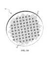
- FIG. 1Dis an enlarged view of a magnetic plate used in the filter device of FIGS. 1B and 1C and configured in accordance with an embodiment of the present technology.
- FIG. 2is an isometric view of a dynamic filtration system having a reservoir configured in accordance with an embodiment of the present technology.
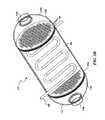
- FIGS. 3A and 3Bare partially transparent isometric views of a filter device configured in accordance with another embodiment of the present technology.
- FIG. 4Ais a partially transparent isometric view of a filter device configured in accordance with a further embodiment of the present technology.
- FIG. 4Bis a partially transparent isometric view illustrating internal features of the filter device of FIG. 4A .
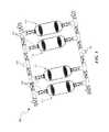
- FIG. 5is an isometric view of a dynamic filtration system having a plurality of filter devices arranged in parallel in accordance with an embodiment of the present technology.
- FIG. 6is an isometric view of a dynamic filtration system including a plurality of filter devices arranged in series in accordance with an embodiment of the present technology.
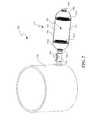
- FIG. 7is a partially transparent isometric view of a dynamic filtration system configured in accordance with yet another embodiment of the present technology.
- the present disclosureis directed toward dynamic filtration systems and associated methods.
- dynamic filtration systemsincluding, for example, a filter device that utilizes a permanent magnetic field and an induced magnetic field to drive filtration of ferrofluids and separate contaminants or other substances from ferrofluids.
- the magnetic fields and the filter mediacan both be adjusted to filter a wide variety of substances, making the dynamic filtration system adaptable to various waste streams.
- ferrofluidrefers to fluids that become magnetized in the presence of a magnetic field.
- the term “fluid”is to be interpreted broadly throughout the specification and can include, for example, liquids, gases, plasmas, and/or solutions, some of which may include solid particles dispersed throughout the fluid.
- contaminantrefers to any substance being removed from a fluid by the filter media.
- FIG. 1Ais a perspective front view of a dynamic filtration system 100 (“system 100 ”) including a filter device 110 configured in accordance with an embodiment of the present technology
- FIGS. 1B and 1Care isometric and isometric cut-away views, respectively, of the filter device 110 of FIG. 1A
- the system 100can include one or more passageways 102 (e.g., tubing, piping, etc.) that feed an unfiltered fluid to the filter device 110 and transfer a filtered fluid away from the filter device 110 .
- passageways 102e.g., tubing, piping, etc.
- the passageways 102can be made from materials that are suitable for transporting fluids, such as plastics (e.g., PE, PP, PTFE, PFA, CPVC, PVC), metals (e.g., copper), and/or other suitable plumbing materials.
- Valves 104can be positioned on or in the passageways 102 to regulate fluid flow to, from, and through the filter device 110 and direct fluid toward and away from the filter device 110 .
- the valves 104can be any of a number of conventional fluid regulation valves, such as ball valves, gate valves, check valves, pinch valves, etc.
- the filter device 110can include a canister, cartridge, or housing 112 having a body portion 114 positioned between opposing end portions (identified individually as a first end portion 116 a and a second end portion 116 b , and referred to collectively as end portions 116 ).
- the end portions 116can include openings (identified individually as a first opening 118 a and a second opening 118 b , and referred to collectively as openings 118 ) that allow fluid to enter and exit the filter device 110 (e.g., from the passageways 102 shown in FIG. 1A ).
- the first opening 118 acan be configured as an inlet through which an unfiltered fluid enters the filter device 110
- the second opening 118 bcan be configured as an outlet through which the filtered fluid exits the filter device 110
- the inlet and the outletcan be reversed.
- the openings 118can also be configured to serve as both the inlet and the outlet depending upon the direction of fluid flow through the system 100 .
- the housing 112can be made from a polymer material, a transmissive material (e.g., glass), and/or other suitable filtration housing materials.
- the housing 112can be a single integrated structure or unit.
- the housing 112can be made by compression molding polymer particles (e.g., polyfin particles made from recycled fluid containers) to form the housing 112 .
- the housing 112can be made by injection molding, extrusion, pultrusion, injection blow molding, thermoforming, or otherwise forming two or more pieces of the housing 112 , and subsequently joining the pieces together by gluing, welding, and/or using suitable fastening methods known in the art.
- the filter device 110can further include an insulated conductor coil 120 (e.g., a solenoid) positioned proximate (e.g., in or around) an outer surface of the housing 112 .
- the coil 120extends along the length of the body portion 114 .
- the coil 120can be positioned along shorter or longer portions of the body portion 114 and/or on other portions of the filter device 110 .
- the coil 120can be formed around a metallic core (e.g., an iron alloy core) and configured to carry an electric current such that the coil 120 forms an electromagnetic field across at least a portion of the filter device 110 .
- the filter device 110can also include magnetic plates (identified individually as a first magnetic plate 122 a and a second magnetic plate 122 b , and referred to collectively as magnetic plates 122 ) positioned proximate the opposing end portions 116 of the housing 112 .
- FIG. 1Dis an enlarged isometric view of one of the magnetic plates 122 .
- the magnetic plate 122includes a matrix of openings, apertures, or holes 124 across the face of the magnetic plate 122 and a plurality of magnets 126 positioned in selected holes 124 .
- the magnetic plate 122itself can also be made from magnetic materials with properties such as ferromagnetism, antiferromagnetism, paramagnetism, or diamagnetism, in response to a magnetic field, and/or may be made from nonmagnetic materials (e.g., ceramics, glass or plastics) that can support the magnets 126 .
- the magnets 126 of the first magnetic plate 122 acan interact with the magnets 126 of the second magnetic plate 122 b to form various magnetic fields such as along the length of the body portion 116 .
- the positions and pole orientations of the magnets 126 in the holes 124can be selected to alter the force and/or direction of the magnetic field between the magnetic plates 122 .
- the magnets 126 and/or proximate materialscan be made from ferromagnetic materials, paramagnetic materials, and/or other magnetic materials. Some ferromagnetic materials, known to those in the art as “hard iron” materials, retain magnetization in the absence of an applied magnetic field, whereas paramagnetic materials, known as “soft iron” materials, are only magnetic in the presence of an externally applied magnetic field. For example, the magnetic field produced by the coil 120 can also magnetize any paramagnetic magnetic materials positioned on or in the fields of magnetic plates 122 . In various embodiments, the ratio of ferromagnetic to paramagnetic materials can be manipulated to alter the strength and/or location of the magnetic field produced by the magnetic plates 122 .
- the magnetic field produced by the magnetic plates 122can also be changed by manipulating the positions and orientations of the magnets 126 .
- changing the orientation of the magnets 126e.g., rotating the magnets 126
- a ferrofluidcan be introduced into the filter device 110 via one of the openings 118 .
- the magnetic field induced by the coil 120 and concentrated or generated by the magnetic plates 122can interact with the ferrofluid (e.g., such that the ferrofluid assumes a structure under the magnetic field) to drive it through the filter device 110 .
- the fluid being filteredis not inherently a ferrofluid (e.g., water, alcohol, glycerin, etc.)
- the fluidcan be pre-treated and loaded with ferromagnetic or iron particles such that it takes on the properties of a ferrofluid and can be used with the filter device 110 .
- the magnetic fields provided by the coil 120 and/or the magnetic plates 122can be manipulated (e.g., by changing the current magnitude or direction, frequency of application, and/or orientation of the magnets 126 in the magnetic plates 122 ) to alter the flow rate of the ferrofluid through the filter device 110 .
- the magnetic fieldscan therefore provide flow impetus or valving (“magnetic valving”) for system 100 .
- the magnetic fieldscan also be manipulated to change properties or characteristics (e.g., viscosity) of the ferrofluid being filtered, and therefore can change the substances filtered from the ferrofluid. Accordingly, the magnetic fields created by the filter device 110 can be used both to treat the fluid and drive filtration (i.e., load and unload the filter device 110 with the ferrofluid).
- the filter device 110can be manipulated to control the size of the precipitate (i.e., the filtered substance).
- the dwell time of the fluidcan be changed by manipulating the magnetic plates 122 to slow the flow rate of the fluid through the filter device 110 .
- the temperature, pressure, and/or other characteristics of the filter device 110can be modified to create a certain collection or precipitate size.
- carbonylscan be used generate iron of a specific particle size and shape.
- the filter device 110can have a cavity 128 that includes and/or is loaded with a filter media 150 through which the ferrofluid is filtered.
- the filter media 150can be introduced into the cavity 128 before filtration and/or during filtration (e.g., in conjunction with the ferrofluid).
- the cavity 128can be pre-loaded with graphene, activated carbon, boron, spinel, zeolite, and/or other suitable filtration substances.
- the cavity 128can be loaded with an architectural construct.
- Architectural constructsare synthetic matrix characterizations of crystals that are primarily comprised of graphene, graphite, boron nitride, and/or another suitable crystal or constituent.
- the configuration and the treatment of these crystalsheavily influences the properties that the architectural construct will exhibit when it experiences certain conditions.
- architectural constructscan be manipulated to obtain the requisite geometry, orientation, and surface tension to load (e.g., adsorb) almost any element or soluble substance.
- the architectural constructcan be configured to load a predetermined substance (e.g., sulfur or a compound containing sulfur such as iron or hydrogen sulfide) introduced into the cavity 128 in a non-fixed state, and selectively filter and/or chemically bind (e.g. form a compound or otherwise reside on or within the surface of ferromagnetic particles) to isolate the predetermined substance and remove it from the fluid.
- a predetermined substancee.g., sulfur or a compound containing sulfur such as iron or hydrogen sulfide
- the architectural constructcan be introduced into the system as the fluid enters the filter device 110 . Additional features and characteristics of architectural constructs are described in U.S. patent application Ser. No. 13/027,214, filed Feb. 14, 2011,now U.S. Patent Publication Number 2011/0206915 A1 and entitled “ARCHITECTURAL CONSTRUCT HAVING FOR EXAMPLE A PLURALITY OF ARCHITECTURAL CRYSTALS”; U.S. patent application Ser. No. 13/584,658, filed concurrently herewith, now U.S. Patent Publication Number 2013/0101808 A1 and entitled “ARCHITECTURAL CONSTRUCT HAVING A PLURALITY OF IMPLEMENTATIONS”; and U.S. patent application Ser. No.
- an architectural constructcan be configured as a substrate made from a sorption media that comprises parallel layers of a sorption material spaced apart from one another by a certain distance or varying distances.
- a substancecan be presented at an edge of the substrate where the sorption media provides access to zones between layers of the sorption material. Heat may be transferred away from the sorption media to facilitate and/or cause the sorption media to load (i.e. absorb and/or adsorb) molecules of the substance into the sorption media.
- a voltage of a first polaritymay be applied to the sorption media to facilitate and/or cause the sorption media to load molecules of the substance.
- a pressure experienced by the sorption mediamay be increased to facilitate and/or cause the sorption media to load molecules of the substance.
- the sorption mediacan also include surface structures that load the substance and/or catalysts that facilitate the loading of a substance into the sorption media.
- a substancecan be unloaded from the sorption media by transferring heat to the sorption media, applying a voltage of an opposite polarity than the first polarity to the sorption media, and/or by reducing a pressure experienced by the sorption media. Additional features and ways of manipulating architectural constructs with sorption substrates are described in U.S. patent application Ser. No. 12/857,515, filed Aug. 16, 2010, now issued as U.S, Pat. No. 8,147,599,B2 and entitled “APPARATUSES AND METHODS FOR STORING AND/OR FILTERING A SUBSTANCE”, which is incorporated herein by reference in its entirety.
- the filter device 110can use the filter media 150 (e.g., an architectural construct) to filter sulfur from a fluid (e.g., natural gas).
- the architectural constructcan first be loaded with iron, iron carbide, various compounds of halogens and iron, and/or other substances or elements that have an affinity to sulfur, and then introduced into the filter device 110 (before or during filtration).
- the sulfur-laden fluidflows through the loaded architectural construct, the sulfur separates from the fluid to join with the iron to form iron sulfide.
- the architectural constructs and/or other filter media 150 in the cavity 128can be configured to selectively remove substances from the ferrofluid as it passes through the filter device 110 .
- an architectural constructcan be configured to remove sulfur from natural gas or renewable fuels.
- the magnetic fields generated by the magnetic plates 122 and the coil 120can drive the ferrofluid through the cavity 128 and, in various embodiments, change the characteristics of the ferrofluid such that certain substances are allowed to pass through the cavity while others are trapped by the filter media 150 .
- the filter device 110allows for numerous variables (e.g., strength and direction of magnetic field, configuration of filter media 150 , etc.) to be manipulated such that a wide variety of substances can be filtered from the ferrofluids, and is therefore highly adaptable to various systems.
- the filtered substancecan be removed from the filter device 110 .
- the filter media 150is loaded with alcohol, water can be flushed through the filter device 110 to unload the alcohol.
- the filter media 150can be flushed with other fluids to remove the loaded substance, or the loaded filter media 150 can be disposed and replaced with a new filter media.
- the loaded substancecan be harvested from the filter media 150 .
- the filter device 110can also be used to harvest various substances, such as copper.
- a copper-rich fluidcan be collected in a reservoir, and iron can be added to the copper fluid to transform it into a ferrofluid that can be introduced into the filter device 110 .
- the iron-infused copper fluidflows through the filter device, the iron is affected by the applied magnetic field while the copper is not. This separates the iron from the copper, and allows the copper to exit the filter device 110 and be harvested in its pure state.
- the filter device 110can also be used in conjunction with sensor systems.
- the filter device 110can electively filter a substance from a fluid, measure the level of that substance with respect to the fluid, and indicate when the level of the substance is above a predetermined threshold.
- the filter device 110can be positioned proximate a fitting in a pipeline to sensor and/or predict when a leak occurs.
- the filter device 110can be used in conjunction with the sensor systems described in U.S. patent application Ser. No. 12/806,634, filed Aug. 16, 2010, now issued as U.S. Pat. No. 8,441,361 B2 entitled“METHODS AND APPARATUSES FOR DETECTION OF PROPERTIES OF FLUID CONVEYANCE SYSTEMS”, which is incorporated herein by reference in its entirety.
- one or both of the end portions 116 of the housing 112can include fluid distribution channels (e.g., staggered spiral-shaped channels) that spread the fluid evenly across the magnetic plates 122 and through the cavity 128 . This reduces overuse of the filter media 150 at the center portion of the cavity 128 and increases the surface area of the filter media 150 that participates in the filtration process.
- the fluid distribution channelscan also include a filter media to provide additional filtration to the system 100 .
- the distribution channelscan be made from a spiraled filter media described in U.S. patent application Ser. No.
- the body portion 114 of the housing 112can include the fluid distribution channels to distribute fluid across and enhance the flow through the cavity 128 .
- FIG. 2is an isometric view of a dynamic filtration system (“system 200 ”) configured in accordance with another embodiment of the present technology.
- the system 200includes the filter device 110 that uses magnetic fields to filter ferrofluids and/or substances presented by actions of ferrofluids.
- the system 200includes a reservoir 230 connected to the filter device 110 via the passageway 102 .
- the reservoir 230can capture and store an unfiltered fluid until it is ready for filtration.
- the reservoir 230can be used as a basin to magnetically infuse the fluid.
- the fluid in the reservoir 230can be loaded with an architectural construct having various specializations such as an iron edge, or certain spacing between iron edges, or other characteristics.
- the direction of flow through the filter device 110may be reversed such that purified or filtered fluids are captured and stored in the reservoir 230 for later use.
- FIGS. 3A and 3Bare partially transparent isometric views of a filter device 310 configured in accordance with another embodiment of the present technology.
- the filter device 310includes features generally similar to the features of the filter device 110 described above with reference to FIGS. 1A-2 .
- the filter device 310includes magnetic plates 122 positioned in the opposing end portions 116 of the housing 112 and the coil 120 around the housing 112 .
- the filter device 310further includes a heat exchanger 332 wrapped around and/or otherwise positioned on the housing 112 such that the heat exchanger 332 can transfer heat to or remove heat from the filter device 310 .
- the heat exchanger 332may transfer heat to the filter device 310 to facilitate reactions during filtration.
- the heat exchanger 332can remove excess heat from exothermic processes that occur during filtration. For example, excess heat is typically produced during the filtration of sour gas (i.e., natural gas containing significant amounts of H 2 S) when the sulfur reacts with iron (e.g., introduced via an architectural construct tailored with iron edge characteristics) to form iron sulfide.
- the filter device 310can include other heat transfer devices known in the art to transfer heat to and/or from the filter device 310 .
- the filter device 310can further include a separator 334 that runs along the length of the body portion 114 of the housing 112 to form two filtration channels.
- the filtration channelscan be configured to run in parallel, while removing different contaminants from the incoming fluid.
- the two or more filtration channels shown in FIG. 3Bcan be loaded with different filter media and/or the magnets 126 in the magnetic plates 122 can be configured differently on either side of the separator 334 to remove different substances from the fluid.
- the filter device 310can include additional separators 334 to create more filtration channels and/or the separator(s) 334 can extend a greater length through the entire housing 112 .
- the separator 334can be made from a nonporous membrane, a polymer material, glass, and/or other suitable materials that form a barricade or divider for certain substances between filtration channels.
- the filter device 310can include another heat exchanger 336 positioned on the separator 334 .
- This inner heat exchanger 336may be particularly beneficial where the separator 334 allows for two separate filtration cycles and thus potentially two different reactions that require heat transfer.
- different heat transfer mechanisms known in the artcan be positioned within the housing 112 to add or remove heat from the filter device 310 .
- FIGS. 4A and 4Bare partially transparent isometric views of a filter device 410 configured in accordance with a further embodiment of the present technology.
- the filter device 410includes features generally similar to the features of the filter device 110 described above with reference to FIGS. 1A-1D .
- the filter device 410includes a third magnetic plate 122 c positioned transversely across the housing 112 , thereby separating the body portion 114 into a first cavity 428 a and a second cavity 428 b .
- This configurationallows the first cavity 428 a to be loaded with a different filter media than the second cavity 428 b such that different substances are removed from the fluid as it flows through the different cavities 428 .
- the third magnetic plate 122 ccan be configured to form different magnetic fields in the first and second cavities 428 a and 428 b , and thus alter their filtration properties (e.g., flow speed, characteristics of the ferrofluid, removal of substances from the fluid, etc.).
- the filter device 410can include additional magnetic plates 122 to form additional cavities 428 , and can accordingly filter fluids in series through a plurality of filtration stages corresponding to each of the cavities 428 .
- FIG. 5is an isometric view of a dynamic filtration system 500 (“system 500 ”) including a plurality of filter devices 110 arranged in parallel with one another in accordance with an embodiment of the present technology.
- the system 500can receive a fluid through an inlet 538 , and the passageways 102 can deliver the fluid to the filter devices 110 .
- the valves 104can be used to direct the fluid to selected fluid devices 110 in various series, parallel or series-parallel permutations.
- the filter devices 110may be in various stages of loading and/or unloading a contaminant from the fluid.
- the system 500can use the valves 104 to direct the fluid toward the filter devices 110 in the loading stage, while allowing the filter devices 110 in the unloading stage to remove the contaminant and recharge (e.g., load with a tailored architectural construct). After filtration, the fluid can exit the system 500 via an outlet 540 opposite the inlet 538 .
- the filter devices 110can be configured to remove different contaminants from the fluid.
- one of the filter devices 110can be configured to remove sulfur and another filter device 110 can be configured to remove copper.
- the resultant purified fluid streamstherefore, each have different properties (e.g., a low sulfur fluid and a low copper fluid).
- the system 500can therefore include a plurality of outlets to separately capture the different purified fluid streams.
- FIG. 6is an isometric view of a dynamic filtration system 600 (“system 600 ”) configured in accordance with another embodiment of the present technology.
- the system 600includes a plurality of the filter devices 310 described above with reference to FIGS. 3A and 3B .
- the filter devicesare coupled together in series rather than in parallel (e.g., as shown in FIG. 5 ).
- each filter device 310can be configured to remove a different substance from a fluid such that the different substances are sequentially removed as the fluid passes through each filter device 310 and the fluid becomes increasingly purified as it moves through the serially coupled filter devices 310 .
- the filter devices 310are configured to remove the same substance from the fluid.
- the system 600can also include inlet and outlet passageways 102 surrounding individual filter devices 310 to allow a fluid to be injected or removed from the system 600 at various points in the series.
- FIG. 7is a partially transparent isometric view of a dynamic filtration system 700 (“system 700 ”) configured in accordance with a further embodiment of the present technology.
- the system 700can include a plurality of filter devices 110 positioned on a manifold 742 .
- the manifold 742can include an opening 744 that is in fluid communication with the openings 118 of the individual filter devices 110 .
- the manifold 742can therefore form a junction between the plurality of filter devices 110 to either deliver fluid to the separate filter devices 110 or funnel fluid from the filter devices 110 (depending the direction of fluid flow through the system 700 ).
- the opening 744 of the manifold 742is configured as an inlet such that fluid flows into the manifold 742 and divides into the individual filter devices 110 .
- the filter devices 110can be configured to remove the same or different contaminants from the fluid.
- the manifold 742can further include fluid distribution channels that direct the fluid substantially evenly into the filter devices 110 and, optionally, pre-filter the fluid before it enters the filter devices 110 (e.g., as described in U.S. patent application Ser. No. 13/584,790, entitled “FLUID DISTRIBUTION FILTER HAVING SPIRAL FILTER MEDIA AND ASSOCIATED METHODS AND SYSTEMS,” and incorporated by reference above).
- the opening 744 of the manifold 742is configured as an outlet that collects the filtered fluid from the filter devices 110 .
- the filter devices shown in the Figuresare cylindrical with dome-shaped end portions.
- the filter devicescan have a variety of other shapes (e.g., cones, rectangular prisms, cubes, spheres etc.), aspect ratios, and must not necessarily be symmetrical about the end portions.
- Certain aspects of the new technology described in the context of particular embodimentsmay be combined or eliminated in other embodiments.
- any one of the filter devices described abovecan be used in conjunction with any of the dynamic filtration systems.
Landscapes
- Chemical & Material Sciences (AREA)
- Chemical Kinetics & Catalysis (AREA)
- Engineering & Computer Science (AREA)
- Water Supply & Treatment (AREA)
- Physics & Mathematics (AREA)
- Electromagnetism (AREA)
- Health & Medical Sciences (AREA)
- General Health & Medical Sciences (AREA)
- Toxicology (AREA)
- Organic Chemistry (AREA)
- Filtering Materials (AREA)
- Reciprocating, Oscillating Or Vibrating Motors (AREA)
Abstract
Description
Claims (28)
Priority Applications (3)
| Application Number | Priority Date | Filing Date | Title |
|---|---|---|---|
| US13/584,705US8617399B2 (en) | 2011-08-12 | 2012-08-13 | Dynamic filtration system and associated methods |
| US13/966,152US20140044600A1 (en) | 2011-08-12 | 2013-08-13 | Device for treating chemical compositions and methods for use thereof |
| US14/145,663US9327226B2 (en) | 2011-08-12 | 2013-12-31 | Dynamic filtration system and associated methods |
Applications Claiming Priority (2)
| Application Number | Priority Date | Filing Date | Title |
|---|---|---|---|
| US201161523228P | 2011-08-12 | 2011-08-12 | |
| US13/584,705US8617399B2 (en) | 2011-08-12 | 2012-08-13 | Dynamic filtration system and associated methods |
Related Child Applications (2)
| Application Number | Title | Priority Date | Filing Date |
|---|---|---|---|
| US13/966,152Continuation-In-PartUS20140044600A1 (en) | 2011-08-12 | 2013-08-13 | Device for treating chemical compositions and methods for use thereof |
| US14/145,663ContinuationUS9327226B2 (en) | 2011-08-12 | 2013-12-31 | Dynamic filtration system and associated methods |
Publications (2)
| Publication Number | Publication Date |
|---|---|
| US20130209320A1 US20130209320A1 (en) | 2013-08-15 |
| US8617399B2true US8617399B2 (en) | 2013-12-31 |
Family
ID=47715663
Family Applications (2)
| Application Number | Title | Priority Date | Filing Date |
|---|---|---|---|
| US13/584,705Expired - Fee RelatedUS8617399B2 (en) | 2011-08-12 | 2012-08-13 | Dynamic filtration system and associated methods |
| US14/145,663Expired - Fee RelatedUS9327226B2 (en) | 2011-08-12 | 2013-12-31 | Dynamic filtration system and associated methods |
Family Applications After (1)
| Application Number | Title | Priority Date | Filing Date |
|---|---|---|---|
| US14/145,663Expired - Fee RelatedUS9327226B2 (en) | 2011-08-12 | 2013-12-31 | Dynamic filtration system and associated methods |
Country Status (2)
| Country | Link |
|---|---|
| US (2) | US8617399B2 (en) |
| WO (1) | WO2013025643A2 (en) |
Cited By (6)
| Publication number | Priority date | Publication date | Assignee | Title |
|---|---|---|---|---|
| US20140044600A1 (en)* | 2011-08-12 | 2014-02-13 | Mcalister Technologies, Llc | Device for treating chemical compositions and methods for use thereof |
| US20140356245A1 (en)* | 2011-08-12 | 2014-12-04 | Mcalister Technologies, Llc | Dynamic filtration system and associated methods |
| US9314719B2 (en) | 2011-08-12 | 2016-04-19 | Mcalister Technologies, Llc | Filter having spiral-shaped distributor channels |
| US9409126B2 (en) | 2009-02-17 | 2016-08-09 | Mcalister Technologies, Llc | Apparatuses and methods for storing and/or filtering a substance |
| US9511663B2 (en) | 2013-05-29 | 2016-12-06 | Mcalister Technologies, Llc | Methods for fuel tank recycling and net hydrogen fuel and carbon goods production along with associated apparatus and systems |
| US9534296B2 (en) | 2013-03-15 | 2017-01-03 | Mcalister Technologies, Llc | Methods of manufacture of engineered materials and devices |
Families Citing this family (7)
| Publication number | Priority date | Publication date | Assignee | Title |
|---|---|---|---|---|
| DE102013008817A1 (en)* | 2013-05-25 | 2014-12-11 | Technische Universität Kaiserslautern | Device for separating particles from a fluid by magnetic separation |
| MX2018008729A (en)* | 2016-01-15 | 2019-02-20 | Metoxs Pte Ltd | Compositions for treatment of fluids. |
| EP3339250A1 (en)* | 2016-12-20 | 2018-06-27 | Nordaq Water Filter Systems AB | Purification device |
| CN107042032A (en)* | 2017-03-06 | 2017-08-15 | 江苏省特种设备安全监督检验研究院南通分院 | Energy-saving graphite multitube smoke duster, its method of work and its repair method |
| WO2018224522A1 (en)* | 2017-06-09 | 2018-12-13 | Brita Gmbh | Liquid treatment cartridge, liquid treatment system and use and manufacture of a liquid treatment cartridge |
| CH715193A1 (en)* | 2018-07-23 | 2020-01-31 | Mueller Drm Ag | Device for separating solids from liquids and gases. |
| WO2024235416A1 (en)* | 2023-05-12 | 2024-11-21 | Эльчин ХАЛИЛОВ | "zeomag" magnetic activation and water filtration device |
Citations (94)
| Publication number | Priority date | Publication date | Assignee | Title |
|---|---|---|---|---|
| US3404061A (en) | 1962-03-21 | 1968-10-01 | Union Carbide Corp | Flexible graphite material of expanded particles compressed together |
| US3830204A (en) | 1972-03-07 | 1974-08-20 | Alister R Mc | Fuel injection-spark ignition system for an internal combustion engine |
| US3935354A (en) | 1970-08-21 | 1976-01-27 | Olcott Eugene L | Shaped articles of pyrolytic graphite-silicon carbide microcomposites |
| US3967256A (en) | 1973-04-26 | 1976-06-29 | Marine And Industrial Developments Limited | Integrity monitoring system for storage tank insulation |
| US4066046A (en) | 1974-07-29 | 1978-01-03 | Mcalister Roy E | Method and apparatus for fuel injection-spark ignition system for an internal combustion engine |
| US4077788A (en) | 1976-04-13 | 1978-03-07 | The United States Of America Asthe Administrator Of The National Aeronautics And Space Administration | Atomic hydrogen storage method and apparatus |
| US4094762A (en) | 1974-11-05 | 1978-06-13 | United Kingdom Atomic Energy Authority | Method for the storage of material |
| US4193827A (en) | 1976-04-13 | 1980-03-18 | The United States Of America As Represented By The Administrator Of The National Aeronautics And Space Administration | Atomic hydrogen storage |
| US4210103A (en) | 1977-04-04 | 1980-07-01 | Southwest Research Institute | Fuel system for and a method of operating a spark-ignited internal combustion engine |
| EP0025858A1 (en) | 1979-09-18 | 1981-04-01 | International Business Machines Corporation | Rechargeable storage means for binding gaseous hydrogen |
| EP0056717A2 (en) | 1981-01-16 | 1982-07-28 | Inoue-Japax Research Incorporated | Magnetic filtration apparatus |
| US4407238A (en) | 1981-10-26 | 1983-10-04 | Conoco Inc. | Methanol dissociation using a copper-chromium-manganese catalyst |
| US4472275A (en)* | 1981-12-30 | 1984-09-18 | Daidotokushuko Kabushikikaisha | Magnetic separator |
| US4495074A (en) | 1981-08-20 | 1985-01-22 | Unitika, Ltd. | Method and apparatus for filtration using ferromagnetic metal fibers |
| US4567857A (en) | 1980-02-26 | 1986-02-04 | The United States Of America As Represented By The Administrator Of The National Aeronautics And Space Administration | Combustion engine system |
| US4588106A (en) | 1983-12-05 | 1986-05-13 | Stark Sr Robert G | Fiberglass molded pressure vessel and method of making same |
| US4600529A (en) | 1983-09-19 | 1986-07-15 | Gas Research Institute | Dehydrogenation of alcohols using alkali carbonate catalysts |
| US4676972A (en) | 1985-07-29 | 1987-06-30 | The Standard Oil Company | Process for the conversion of alcohols to gaseous products |
| US5067447A (en) | 1988-07-26 | 1991-11-26 | Kabushiki Kaisha Toyoda Jidoshokki Seisakusho | Method for controlling heat of a metal hydride container |
| US5220080A (en) | 1992-06-29 | 1993-06-15 | Sun Company, Inc. (R&M) | Chromia on metal oxide catalysts for the oxidation of methane to methanol |
| US5284996A (en) | 1992-02-28 | 1994-02-08 | Mcdonnell Douglas Corporation | Waste gas storage |
| JPH06182125A (en) | 1992-12-22 | 1994-07-05 | Japan Organo Co Ltd | Electromagnetic filter device |
| US5343699A (en) | 1989-06-12 | 1994-09-06 | Mcalister Roy E | Method and apparatus for improved operation of internal combustion engines |
| JPH08206420A (en) | 1994-11-16 | 1996-08-13 | Hitachi Ltd | Magnetic separation device |
| WO1996041745A1 (en) | 1995-06-09 | 1996-12-27 | Zvi Horovitz | High bulk density, parallel carbon fibers |
| US5618501A (en) | 1992-12-09 | 1997-04-08 | Emitec, Gesellschaft Fuer Emissionstechnologie Mbh | Catalytic converter with two or more honeycomb bodies in a casing tube and method for its production |
| US5639707A (en) | 1992-05-05 | 1997-06-17 | Ucar Carbon Technology Corporation | Process for the storage of methane with activated carbon |
| US5648184A (en) | 1995-04-13 | 1997-07-15 | Toyo Boseki Kabushiki Kaisha | Electrode material for flow-through type electrolytic cell, wherein the electrode comprises carbonaceous material having at least one groove |
| US5772938A (en) | 1996-05-10 | 1998-06-30 | Sharp; Bruce R. | Composite storage tank having double wall characteristics |
| US5822838A (en) | 1996-02-01 | 1998-10-20 | Lockheed Martin Corporation | High performance, thin metal lined, composite overwrapped pressure vessel |
| US6015065A (en) | 1997-08-29 | 2000-01-18 | Mcalister; Roy E. | Compact fluid storage system |
| US6015041A (en) | 1996-04-01 | 2000-01-18 | Westinghouse Savannah River Company | Apparatus and methods for storing and releasing hydrogen |
| US6155212A (en) | 1989-06-12 | 2000-12-05 | Mcalister; Roy E. | Method and apparatus for operation of combustion engines |
| JP2001254897A (en) | 2000-03-10 | 2001-09-21 | Honda Motor Co Ltd | Hydrogen storage device |
| JP2001295995A (en) | 2000-04-11 | 2001-10-26 | Honda Motor Co Ltd | Hydrogen storage tank |
| JP2002128501A (en) | 2000-10-18 | 2002-05-09 | Sony Corp | Method for gas storage and fuel cell |
| WO2002056400A2 (en) | 2001-01-09 | 2002-07-18 | Questair Technologies Inc | Fuel cell power plant with energy recovery from fuel storage |
| US6432176B1 (en) | 1998-12-15 | 2002-08-13 | Mannesmann Ag | Device for storing compressed gas |
| US6466597B1 (en) | 1998-06-17 | 2002-10-15 | Matsushita Electric Industrial Co., Ltd. | Semiconductor laser device |
| EP1256369A2 (en) | 2001-05-08 | 2002-11-13 | Fleetguard, Inc. | Dual section exhaust aftertreatment filter and method |
| US6503584B1 (en) | 1997-08-29 | 2003-01-07 | Mcalister Roy E. | Compact fluid storage system |
| US6540816B2 (en) | 2001-08-23 | 2003-04-01 | Fleetguard, Inc. | Regenerable filter with localized and efficient heating |
| US20030167923A1 (en) | 2000-05-10 | 2003-09-11 | Frank Grote | Tank for the reversible storage of hydrogen |
| WO2003078252A2 (en) | 2002-03-15 | 2003-09-25 | Fuelsell Technologies, Inc. | Method and apparatus for a hydrogen fuel cassette distribution and recovery system |
| US6626981B2 (en) | 2000-07-07 | 2003-09-30 | Advanced Fuel Research, Inc. | Microporous carbons for gas storage |
| US20030209149A1 (en) | 2002-05-09 | 2003-11-13 | Vitaliy Myasnikov | Honeycomb hydrogen storage structure |
| US6660063B2 (en) | 1998-03-27 | 2003-12-09 | Advanced Technology Materials, Inc | Sorbent-based gas storage and delivery system |
| WO2004016982A2 (en) | 2002-08-14 | 2004-02-26 | Texaco Ovonic Hydrogen Systems Llc | Onboard hydrogen storage unit with heat transfer system for use in a hydrogen powered vehicle |
| US6709497B2 (en) | 2002-05-09 | 2004-03-23 | Texaco Ovonic Hydrogen Systems Llc | Honeycomb hydrogen storage structure |
| WO2004024845A2 (en) | 2002-09-10 | 2004-03-25 | Fuelsell Technologies, Inc. | Hydrogen storage, distribution, and recovery system |
| US20040076561A1 (en) | 2000-05-23 | 2004-04-22 | Hisashi Kajiura | Method for producing hydrogen storage material and hydrogen storing and desorbing apparatus |
| US6743278B1 (en) | 2002-12-10 | 2004-06-01 | Advanced Technology Materials, Inc. | Gas storage and dispensing system with monolithic carbon adsorbent |
| WO2004050798A2 (en) | 2002-12-04 | 2004-06-17 | Fuelsell Technologies, Inc. | Hydrogen storage, distribution, and recovery system |
| US6756140B1 (en) | 1989-06-12 | 2004-06-29 | Mcalister Roy E. | Energy conversion system |
| JP2004268022A (en) | 2003-02-18 | 2004-09-30 | Nissan Motor Co Ltd | Hydrogen storage material, method for producing hydrogen storage material, hydrogen storage tank, hydrogen storage system, and fuel cell vehicle |
| WO2004108590A2 (en) | 2002-07-10 | 2004-12-16 | Fuelsell Technologies, Inc. | Improved methods for hydrogen storage using doped alanate compositions |
| US6834508B2 (en) | 2002-08-29 | 2004-12-28 | Nanomix, Inc. | Hydrogen storage and supply system |
| US6918382B2 (en) | 2002-08-26 | 2005-07-19 | Energy Conversion Devices, Inc. | Hydrogen powered scooter |
| JP2005199163A (en) | 2004-01-15 | 2005-07-28 | Trial Corp | Collection by filtration apparatus and method utilizing magnetic bead |
| JP2006035174A (en) | 2004-07-29 | 2006-02-09 | Toyota Motor Corp | Hydrogen storage and its manufacture and use |
| US20060048808A1 (en) | 2004-09-09 | 2006-03-09 | Ruckman Jack H | Solar, catalytic, hydrogen generation apparatus and method |
| US20060088739A1 (en) | 2004-10-26 | 2006-04-27 | Energy Conversion Devices, Inc. | Power generation and supply system |
| US7048839B2 (en) | 2002-01-29 | 2006-05-23 | Mitsubishi Corporation | System and method for generating high pressure hydrogen |
| US7097748B2 (en) | 2002-04-23 | 2006-08-29 | University Of Massachusetts | Electrolyzer pressure equalization system |
| US7112239B2 (en) | 2003-05-20 | 2006-09-26 | Toyota Jidosha Kabushiki Kaisha | Gas storage apparatus |
| US7169214B2 (en) | 2003-01-24 | 2007-01-30 | Kabushiki Kaisha Toyota Jidoshokki | High pressure tank |
| US7172645B1 (en) | 2003-06-30 | 2007-02-06 | Sun Microsystems, Inc. | Gas filtration and storage using activated carbon/graphite foam monoliths |
| US7175826B2 (en) | 2003-12-29 | 2007-02-13 | General Electric Company | Compositions and methods for hydrogen storage and recovery |
| JP2007077265A (en) | 2005-09-14 | 2007-03-29 | Nippon Oil Corp | Porous material and method for producing the same |
| US7241331B2 (en) | 2003-11-18 | 2007-07-10 | Industrial Technology Research Institute | Metal hydride canister apparatus |
| US7306862B2 (en) | 2001-05-23 | 2007-12-11 | Forschungszentrum Karlsruhe Gmbh | Removable storage method for hydrogen and hydrogen reservoir |
| US7320726B2 (en) | 2004-12-31 | 2008-01-22 | Chih-Kang Shih | Hydrogen storage apparatus |
| US7323043B2 (en) | 2003-07-28 | 2008-01-29 | Deere & Company | Storage container associated with a thermal energy management system |
| US7325401B1 (en) | 2004-04-13 | 2008-02-05 | Brayton Energy, Llc | Power conversion systems |
| US7331178B2 (en) | 2003-01-21 | 2008-02-19 | Los Angeles Advisory Services Inc | Hybrid generation with alternative fuel sources |
| US7399325B1 (en) | 2002-03-15 | 2008-07-15 | Fuelsell Technologies, Inc. | Method and apparatus for a hydrogen fuel cassette distribution and recovery system |
| US20080203101A1 (en) | 2003-03-25 | 2008-08-28 | Toyota Jidosha Kabushiki Kaisha | Gas storage tank and method of manufacturing the same |
| US20080226532A1 (en) | 2006-10-27 | 2008-09-18 | Zhigang Zak-Fang | Light metal based material system for hydrogen storage |
| US7431756B2 (en) | 2002-05-09 | 2008-10-07 | Ovonic Hydrogen Systems Llc | Modular metal hydride hydrogen storage system |
| US7455723B2 (en) | 2005-12-22 | 2008-11-25 | Modine Manufacturing Company | Hydrogen storage and release device |
| US20090014062A1 (en) | 2004-01-22 | 2009-01-15 | Showa Denko K.K. | Metal Oxide Dispersion, Metal Oxide Electrode Film, and Dye Sensitized Solar Cell |
| US7494530B2 (en) | 2002-12-10 | 2009-02-24 | Advanced Technology Materials, Inc. | Gas storage and dispensing system with monolithic carbon adsorbent |
| US20090229555A1 (en) | 2004-04-21 | 2009-09-17 | Angstore Technologies Ltd. | Storage Systems For Adsorbable Gaseous Fuel And Methods Of Producing The Same |
| US7594939B2 (en) | 2004-09-01 | 2009-09-29 | Hyogen, Ltd. | System for hydrogen storage and generation |
| US7712605B2 (en) | 2006-12-19 | 2010-05-11 | Honda Motor Co., Ltd. | Gas storage container with gas absorbing or adsorbing material |
| US7727492B2 (en) | 2006-06-14 | 2010-06-01 | Ovonic Hydrogen Systems Llc | Apparatus for refueling on-board metal hydride hydrogen storage tank |
| US7771512B2 (en) | 2005-06-24 | 2010-08-10 | Washington State University Research Foundation | Apparatus with high surface area nanostructures for hydrogen storage, and methods of storing hydrogen |
| US7780747B2 (en) | 2003-10-14 | 2010-08-24 | Advanced Technology Materials, Inc. | Apparatus and method for hydrogen generation from gaseous hydride |
| US20110041519A1 (en) | 2009-02-17 | 2011-02-24 | Mcalister Technologies, Llc | Apparatuses and methods for storing and/or filtering a substance |
| US7911071B2 (en) | 2007-11-06 | 2011-03-22 | Devine Timothy J | Systems and methods for producing, shipping, distributing, and storing hydrogen |
| US8002880B2 (en) | 2002-12-10 | 2011-08-23 | Advanced Technology Materials, Inc. | Gas storage and dispensing system with monolithic carbon adsorbent |
| US20110206915A1 (en)* | 2009-02-17 | 2011-08-25 | Mcalister Technologies, Llc | Architectural construct having for example a plurality of architectural crystals |
| US20130064979A1 (en)* | 2011-08-12 | 2013-03-14 | Mcalister Technologies, Llc | Methods for manufacturing architectural constructs |
| US8441361B2 (en)* | 2010-02-13 | 2013-05-14 | Mcallister Technologies, Llc | Methods and apparatuses for detection of properties of fluid conveyance systems |
Family Cites Families (2)
| Publication number | Priority date | Publication date | Assignee | Title |
|---|---|---|---|---|
| US8617399B2 (en)* | 2011-08-12 | 2013-12-31 | Mcalister Technologies, Llc | Dynamic filtration system and associated methods |
| WO2013025654A2 (en) | 2011-08-12 | 2013-02-21 | Mcalister Technologies, Llc | Fluid distribution filter having spiral filter media and associated systems and methods |
- 2012
- 2012-08-13USUS13/584,705patent/US8617399B2/ennot_activeExpired - Fee Related
- 2012-08-13WOPCT/US2012/050650patent/WO2013025643A2/enactiveApplication Filing
- 2013
- 2013-12-31USUS14/145,663patent/US9327226B2/ennot_activeExpired - Fee Related
Patent Citations (108)
| Publication number | Priority date | Publication date | Assignee | Title |
|---|---|---|---|---|
| US3404061A (en) | 1962-03-21 | 1968-10-01 | Union Carbide Corp | Flexible graphite material of expanded particles compressed together |
| US3935354A (en) | 1970-08-21 | 1976-01-27 | Olcott Eugene L | Shaped articles of pyrolytic graphite-silicon carbide microcomposites |
| US3830204A (en) | 1972-03-07 | 1974-08-20 | Alister R Mc | Fuel injection-spark ignition system for an internal combustion engine |
| US3967256A (en) | 1973-04-26 | 1976-06-29 | Marine And Industrial Developments Limited | Integrity monitoring system for storage tank insulation |
| US4066046A (en) | 1974-07-29 | 1978-01-03 | Mcalister Roy E | Method and apparatus for fuel injection-spark ignition system for an internal combustion engine |
| US4094762A (en) | 1974-11-05 | 1978-06-13 | United Kingdom Atomic Energy Authority | Method for the storage of material |
| US4077788A (en) | 1976-04-13 | 1978-03-07 | The United States Of America Asthe Administrator Of The National Aeronautics And Space Administration | Atomic hydrogen storage method and apparatus |
| US4193827A (en) | 1976-04-13 | 1980-03-18 | The United States Of America As Represented By The Administrator Of The National Aeronautics And Space Administration | Atomic hydrogen storage |
| US4210103A (en) | 1977-04-04 | 1980-07-01 | Southwest Research Institute | Fuel system for and a method of operating a spark-ignited internal combustion engine |
| EP0025858A1 (en) | 1979-09-18 | 1981-04-01 | International Business Machines Corporation | Rechargeable storage means for binding gaseous hydrogen |
| US4567857A (en) | 1980-02-26 | 1986-02-04 | The United States Of America As Represented By The Administrator Of The National Aeronautics And Space Administration | Combustion engine system |
| EP0056717A2 (en) | 1981-01-16 | 1982-07-28 | Inoue-Japax Research Incorporated | Magnetic filtration apparatus |
| US4495074A (en) | 1981-08-20 | 1985-01-22 | Unitika, Ltd. | Method and apparatus for filtration using ferromagnetic metal fibers |
| US4407238A (en) | 1981-10-26 | 1983-10-04 | Conoco Inc. | Methanol dissociation using a copper-chromium-manganese catalyst |
| US4472275A (en)* | 1981-12-30 | 1984-09-18 | Daidotokushuko Kabushikikaisha | Magnetic separator |
| US4600529A (en) | 1983-09-19 | 1986-07-15 | Gas Research Institute | Dehydrogenation of alcohols using alkali carbonate catalysts |
| US4588106A (en) | 1983-12-05 | 1986-05-13 | Stark Sr Robert G | Fiberglass molded pressure vessel and method of making same |
| US4676972A (en) | 1985-07-29 | 1987-06-30 | The Standard Oil Company | Process for the conversion of alcohols to gaseous products |
| US5067447A (en) | 1988-07-26 | 1991-11-26 | Kabushiki Kaisha Toyoda Jidoshokki Seisakusho | Method for controlling heat of a metal hydride container |
| US6155212A (en) | 1989-06-12 | 2000-12-05 | Mcalister; Roy E. | Method and apparatus for operation of combustion engines |
| US5343699A (en) | 1989-06-12 | 1994-09-06 | Mcalister Roy E | Method and apparatus for improved operation of internal combustion engines |
| US6756140B1 (en) | 1989-06-12 | 2004-06-29 | Mcalister Roy E. | Energy conversion system |
| US5284996A (en) | 1992-02-28 | 1994-02-08 | Mcdonnell Douglas Corporation | Waste gas storage |
| US5639707A (en) | 1992-05-05 | 1997-06-17 | Ucar Carbon Technology Corporation | Process for the storage of methane with activated carbon |
| US5220080A (en) | 1992-06-29 | 1993-06-15 | Sun Company, Inc. (R&M) | Chromia on metal oxide catalysts for the oxidation of methane to methanol |
| US5618501A (en) | 1992-12-09 | 1997-04-08 | Emitec, Gesellschaft Fuer Emissionstechnologie Mbh | Catalytic converter with two or more honeycomb bodies in a casing tube and method for its production |
| JPH06182125A (en) | 1992-12-22 | 1994-07-05 | Japan Organo Co Ltd | Electromagnetic filter device |
| JPH08206420A (en) | 1994-11-16 | 1996-08-13 | Hitachi Ltd | Magnetic separation device |
| US5648184A (en) | 1995-04-13 | 1997-07-15 | Toyo Boseki Kabushiki Kaisha | Electrode material for flow-through type electrolytic cell, wherein the electrode comprises carbonaceous material having at least one groove |
| WO1996041745A1 (en) | 1995-06-09 | 1996-12-27 | Zvi Horovitz | High bulk density, parallel carbon fibers |
| US5822838A (en) | 1996-02-01 | 1998-10-20 | Lockheed Martin Corporation | High performance, thin metal lined, composite overwrapped pressure vessel |
| US6015041A (en) | 1996-04-01 | 2000-01-18 | Westinghouse Savannah River Company | Apparatus and methods for storing and releasing hydrogen |
| US5772938A (en) | 1996-05-10 | 1998-06-30 | Sharp; Bruce R. | Composite storage tank having double wall characteristics |
| US6015065A (en) | 1997-08-29 | 2000-01-18 | Mcalister; Roy E. | Compact fluid storage system |
| US6503584B1 (en) | 1997-08-29 | 2003-01-07 | Mcalister Roy E. | Compact fluid storage system |
| US6660063B2 (en) | 1998-03-27 | 2003-12-09 | Advanced Technology Materials, Inc | Sorbent-based gas storage and delivery system |
| US6466597B1 (en) | 1998-06-17 | 2002-10-15 | Matsushita Electric Industrial Co., Ltd. | Semiconductor laser device |
| US6432176B1 (en) | 1998-12-15 | 2002-08-13 | Mannesmann Ag | Device for storing compressed gas |
| JP2001254897A (en) | 2000-03-10 | 2001-09-21 | Honda Motor Co Ltd | Hydrogen storage device |
| JP2001295995A (en) | 2000-04-11 | 2001-10-26 | Honda Motor Co Ltd | Hydrogen storage tank |
| US20030167923A1 (en) | 2000-05-10 | 2003-09-11 | Frank Grote | Tank for the reversible storage of hydrogen |
| US20040076561A1 (en) | 2000-05-23 | 2004-04-22 | Hisashi Kajiura | Method for producing hydrogen storage material and hydrogen storing and desorbing apparatus |
| US6626981B2 (en) | 2000-07-07 | 2003-09-30 | Advanced Fuel Research, Inc. | Microporous carbons for gas storage |
| JP2002128501A (en) | 2000-10-18 | 2002-05-09 | Sony Corp | Method for gas storage and fuel cell |
| US8015808B2 (en) | 2001-01-09 | 2011-09-13 | G4 Insights Inc. | Power plant with energy recovery from fuel storage |
| WO2002056400A2 (en) | 2001-01-09 | 2002-07-18 | Questair Technologies Inc | Fuel cell power plant with energy recovery from fuel storage |
| US20020112479A1 (en) | 2001-01-09 | 2002-08-22 | Keefer Bowie G. | Power plant with energy recovery from fuel storage |
| EP1256369A2 (en) | 2001-05-08 | 2002-11-13 | Fleetguard, Inc. | Dual section exhaust aftertreatment filter and method |
| US7306862B2 (en) | 2001-05-23 | 2007-12-11 | Forschungszentrum Karlsruhe Gmbh | Removable storage method for hydrogen and hydrogen reservoir |
| US6540816B2 (en) | 2001-08-23 | 2003-04-01 | Fleetguard, Inc. | Regenerable filter with localized and efficient heating |
| US7048839B2 (en) | 2002-01-29 | 2006-05-23 | Mitsubishi Corporation | System and method for generating high pressure hydrogen |
| US7169489B2 (en) | 2002-03-15 | 2007-01-30 | Fuelsell Technologies, Inc. | Hydrogen storage, distribution, and recovery system |
| WO2003078252A2 (en) | 2002-03-15 | 2003-09-25 | Fuelsell Technologies, Inc. | Method and apparatus for a hydrogen fuel cassette distribution and recovery system |
| US7399325B1 (en) | 2002-03-15 | 2008-07-15 | Fuelsell Technologies, Inc. | Method and apparatus for a hydrogen fuel cassette distribution and recovery system |
| US8066946B2 (en) | 2002-03-15 | 2011-11-29 | Redmond Scott D | Hydrogen storage, distribution, and recovery system |
| US7097748B2 (en) | 2002-04-23 | 2006-08-29 | University Of Massachusetts | Electrolyzer pressure equalization system |
| US6709497B2 (en) | 2002-05-09 | 2004-03-23 | Texaco Ovonic Hydrogen Systems Llc | Honeycomb hydrogen storage structure |
| US7431756B2 (en) | 2002-05-09 | 2008-10-07 | Ovonic Hydrogen Systems Llc | Modular metal hydride hydrogen storage system |
| US20030209149A1 (en) | 2002-05-09 | 2003-11-13 | Vitaliy Myasnikov | Honeycomb hydrogen storage structure |
| WO2004108590A2 (en) | 2002-07-10 | 2004-12-16 | Fuelsell Technologies, Inc. | Improved methods for hydrogen storage using doped alanate compositions |
| US7011768B2 (en) | 2002-07-10 | 2006-03-14 | Fuelsell Technologies, Inc. | Methods for hydrogen storage using doped alanate compositions |
| US6918430B2 (en) | 2002-08-14 | 2005-07-19 | Texaco Ovonic Hydrogen Systems Llc | Onboard hydrogen storage unit with heat transfer system for use in a hydrogen powered vehicle |
| US7363965B2 (en) | 2002-08-14 | 2008-04-29 | Ovonic Hydrogen Systems Llc | Onboard hydrogen storage unit with heat transfer system for use in a hydrogen powered vehicle |
| US6860923B2 (en) | 2002-08-14 | 2005-03-01 | Texaco Ovonic Hydrogen Systems Llc | Onboard hydrogen storage unit with heat transfer system for use in a hydrogen powered vehicle |
| WO2004016982A2 (en) | 2002-08-14 | 2004-02-26 | Texaco Ovonic Hydrogen Systems Llc | Onboard hydrogen storage unit with heat transfer system for use in a hydrogen powered vehicle |
| US6918382B2 (en) | 2002-08-26 | 2005-07-19 | Energy Conversion Devices, Inc. | Hydrogen powered scooter |
| US6834508B2 (en) | 2002-08-29 | 2004-12-28 | Nanomix, Inc. | Hydrogen storage and supply system |
| WO2004024845A2 (en) | 2002-09-10 | 2004-03-25 | Fuelsell Technologies, Inc. | Hydrogen storage, distribution, and recovery system |
| WO2004050798A2 (en) | 2002-12-04 | 2004-06-17 | Fuelsell Technologies, Inc. | Hydrogen storage, distribution, and recovery system |
| US6743278B1 (en) | 2002-12-10 | 2004-06-01 | Advanced Technology Materials, Inc. | Gas storage and dispensing system with monolithic carbon adsorbent |
| US7494530B2 (en) | 2002-12-10 | 2009-02-24 | Advanced Technology Materials, Inc. | Gas storage and dispensing system with monolithic carbon adsorbent |
| US7455719B2 (en) | 2002-12-10 | 2008-11-25 | Advanced Technology Materials, Inc. | Gas storage and dispensing system with monolithic carbon adsorbent |
| US8002880B2 (en) | 2002-12-10 | 2011-08-23 | Advanced Technology Materials, Inc. | Gas storage and dispensing system with monolithic carbon adsorbent |
| WO2004053383A2 (en) | 2002-12-10 | 2004-06-24 | Advanced Technology Materials, Inc. | Gas storage and dispensing system with monolithic carbon adsorbent |
| US6939394B2 (en) | 2002-12-10 | 2005-09-06 | Advanced Technology Materials, Inc. | Gas storage and dispensing system with monolithic carbon adsorbent |
| US7331178B2 (en) | 2003-01-21 | 2008-02-19 | Los Angeles Advisory Services Inc | Hybrid generation with alternative fuel sources |
| US7169214B2 (en) | 2003-01-24 | 2007-01-30 | Kabushiki Kaisha Toyota Jidoshokki | High pressure tank |
| JP2004268022A (en) | 2003-02-18 | 2004-09-30 | Nissan Motor Co Ltd | Hydrogen storage material, method for producing hydrogen storage material, hydrogen storage tank, hydrogen storage system, and fuel cell vehicle |
| US20080203101A1 (en) | 2003-03-25 | 2008-08-28 | Toyota Jidosha Kabushiki Kaisha | Gas storage tank and method of manufacturing the same |
| US7418782B2 (en) | 2003-03-25 | 2008-09-02 | Toyota Jidosha Kabushiki Kaisha | Method of manufacturing a gas storage tank |
| US7112239B2 (en) | 2003-05-20 | 2006-09-26 | Toyota Jidosha Kabushiki Kaisha | Gas storage apparatus |
| US7172645B1 (en) | 2003-06-30 | 2007-02-06 | Sun Microsystems, Inc. | Gas filtration and storage using activated carbon/graphite foam monoliths |
| US7323043B2 (en) | 2003-07-28 | 2008-01-29 | Deere & Company | Storage container associated with a thermal energy management system |
| US7780747B2 (en) | 2003-10-14 | 2010-08-24 | Advanced Technology Materials, Inc. | Apparatus and method for hydrogen generation from gaseous hydride |
| US7241331B2 (en) | 2003-11-18 | 2007-07-10 | Industrial Technology Research Institute | Metal hydride canister apparatus |
| US7175826B2 (en) | 2003-12-29 | 2007-02-13 | General Electric Company | Compositions and methods for hydrogen storage and recovery |
| JP2005199163A (en) | 2004-01-15 | 2005-07-28 | Trial Corp | Collection by filtration apparatus and method utilizing magnetic bead |
| US20090014062A1 (en) | 2004-01-22 | 2009-01-15 | Showa Denko K.K. | Metal Oxide Dispersion, Metal Oxide Electrode Film, and Dye Sensitized Solar Cell |
| US7325401B1 (en) | 2004-04-13 | 2008-02-05 | Brayton Energy, Llc | Power conversion systems |
| US20090229555A1 (en) | 2004-04-21 | 2009-09-17 | Angstore Technologies Ltd. | Storage Systems For Adsorbable Gaseous Fuel And Methods Of Producing The Same |
| JP2006035174A (en) | 2004-07-29 | 2006-02-09 | Toyota Motor Corp | Hydrogen storage and its manufacture and use |
| US7594939B2 (en) | 2004-09-01 | 2009-09-29 | Hyogen, Ltd. | System for hydrogen storage and generation |
| US20060048808A1 (en) | 2004-09-09 | 2006-03-09 | Ruckman Jack H | Solar, catalytic, hydrogen generation apparatus and method |
| US20060088739A1 (en) | 2004-10-26 | 2006-04-27 | Energy Conversion Devices, Inc. | Power generation and supply system |
| US7320726B2 (en) | 2004-12-31 | 2008-01-22 | Chih-Kang Shih | Hydrogen storage apparatus |
| US7771512B2 (en) | 2005-06-24 | 2010-08-10 | Washington State University Research Foundation | Apparatus with high surface area nanostructures for hydrogen storage, and methods of storing hydrogen |
| JP2007077265A (en) | 2005-09-14 | 2007-03-29 | Nippon Oil Corp | Porous material and method for producing the same |
| US7455723B2 (en) | 2005-12-22 | 2008-11-25 | Modine Manufacturing Company | Hydrogen storage and release device |
| US7727492B2 (en) | 2006-06-14 | 2010-06-01 | Ovonic Hydrogen Systems Llc | Apparatus for refueling on-board metal hydride hydrogen storage tank |
| US20080226532A1 (en) | 2006-10-27 | 2008-09-18 | Zhigang Zak-Fang | Light metal based material system for hydrogen storage |
| US7712605B2 (en) | 2006-12-19 | 2010-05-11 | Honda Motor Co., Ltd. | Gas storage container with gas absorbing or adsorbing material |
| US7911071B2 (en) | 2007-11-06 | 2011-03-22 | Devine Timothy J | Systems and methods for producing, shipping, distributing, and storing hydrogen |
| US20110206915A1 (en)* | 2009-02-17 | 2011-08-25 | Mcalister Technologies, Llc | Architectural construct having for example a plurality of architectural crystals |
| US20110041519A1 (en) | 2009-02-17 | 2011-02-24 | Mcalister Technologies, Llc | Apparatuses and methods for storing and/or filtering a substance |
| US8147599B2 (en)* | 2009-02-17 | 2012-04-03 | Mcalister Technologies, Llc | Apparatuses and methods for storing and/or filtering a substance |
| US8441361B2 (en)* | 2010-02-13 | 2013-05-14 | Mcallister Technologies, Llc | Methods and apparatuses for detection of properties of fluid conveyance systems |
| US20130064979A1 (en)* | 2011-08-12 | 2013-03-14 | Mcalister Technologies, Llc | Methods for manufacturing architectural constructs |
| US20130101808A1 (en)* | 2011-08-12 | 2013-04-25 | Mcalister Technologies, Llc | Architectural construct having a plurality of implementations |
Non-Patent Citations (6)
| Title |
|---|
| Dash, J.C., "Two-Dimensional Matter." Scientific American. May 1973. pp. 30-40. |
| Donnet et al., "Carbon Black: Physics, Chemistry, and Elastomer Reinforcement," New York: M. Dekker, 1976. pp. 16-18. |
| International Search Report and Written Opinion for Application No. PCT/US2012/050650; Applicant: McAlister Technologies, LLC.; Date of Mailing: Feb. 25, 2013, 9 pages. |
| Japanese Office Action for PCT/US10/45668; Applicant: McAlister Technologies, LLC, Date of Mailing: Aug. 21, 2012, 4 pages. |
| Steinberg, Meyer, "The Hy-C Process (thermal Decomposition of Natural Gas) Potentially the Lowest Cost Source of Hydrogen with the Least CO2 Emission," Energy Conversion and Management, vol. 36, No. 6-9 (1995), pp. 791-796. |
| Sun et al. "High-pressure Laminar Flame Speeds and Kinetic Modeling of Carbon Monoxide/hydrogen Combustion." Proceedings of the Combustion Institute, vol. 31, Issue 1 (Jan. 2007). pp. 439-446. |
Cited By (7)
| Publication number | Priority date | Publication date | Assignee | Title |
|---|---|---|---|---|
| US9409126B2 (en) | 2009-02-17 | 2016-08-09 | Mcalister Technologies, Llc | Apparatuses and methods for storing and/or filtering a substance |
| US20140044600A1 (en)* | 2011-08-12 | 2014-02-13 | Mcalister Technologies, Llc | Device for treating chemical compositions and methods for use thereof |
| US20140356245A1 (en)* | 2011-08-12 | 2014-12-04 | Mcalister Technologies, Llc | Dynamic filtration system and associated methods |
| US9314719B2 (en) | 2011-08-12 | 2016-04-19 | Mcalister Technologies, Llc | Filter having spiral-shaped distributor channels |
| US9327226B2 (en)* | 2011-08-12 | 2016-05-03 | Mcalister Technologies, Llc | Dynamic filtration system and associated methods |
| US9534296B2 (en) | 2013-03-15 | 2017-01-03 | Mcalister Technologies, Llc | Methods of manufacture of engineered materials and devices |
| US9511663B2 (en) | 2013-05-29 | 2016-12-06 | Mcalister Technologies, Llc | Methods for fuel tank recycling and net hydrogen fuel and carbon goods production along with associated apparatus and systems |
Also Published As
| Publication number | Publication date |
|---|---|
| US20140356245A1 (en) | 2014-12-04 |
| WO2013025643A2 (en) | 2013-02-21 |
| WO2013025643A3 (en) | 2013-04-25 |
| US20130209320A1 (en) | 2013-08-15 |
| US9327226B2 (en) | 2016-05-03 |
Similar Documents
| Publication | Publication Date | Title |
|---|---|---|
| US8617399B2 (en) | Dynamic filtration system and associated methods | |
| US20140044600A1 (en) | Device for treating chemical compositions and methods for use thereof | |
| US20130277305A1 (en) | Selectively perforated graphene membranes for compound harvest, capture and retention | |
| US9833748B2 (en) | Perforated graphene deionization or desalination | |
| US9314719B2 (en) | Filter having spiral-shaped distributor channels | |
| US9931640B2 (en) | Magnetic filter systems and methods | |
| CA2828358C (en) | Magnetic-separation filter device | |
| AU2004263451A1 (en) | Waste water treatment system by superconductive magentic separation | |
| KR102477045B1 (en) | Apparatus and method for circulating liquid | |
| CN104096408A (en) | Fluid purifier and bypass device used for fluid filtration system | |
| CN210815695U (en) | High gradient magnetic separator and magnetic separation system | |
| WO2015023573A2 (en) | Device for treating chemical compositions and methods for use thereof | |
| CN105170316B (en) | Device and method for achieving molecule/ion-level separation of homogeneous mixing liquid through magnetizing force | |
| WO2017199031A1 (en) | Continuous moving bed chromatography | |
| US20160289098A1 (en) | Microscale-based device for purifying fluid and method of use | |
| JP2010172827A (en) | Water treatment apparatus | |
| JP3826199B2 (en) | Magnetic separation device | |
| KR20120067467A (en) | Oxygen magnetic separator in air | |
| US20140134717A1 (en) | Fluid treatment apparatus and method | |
| CA2895088A1 (en) | Perforated graphene deionization or desalination | |
| KR101995456B1 (en) | Fe ADSORPTION AND REMOVAL SYSTEM IN WATER USING NEODYMIUM MAGNET | |
| CN109069963A (en) | nozzle filter | |
| CN203469623U (en) | Fluid purification device | |
| Mori et al. | Design and trial production of magnetic filter for medical protein screening system using high gradient magnetic separation | |
| CN102680618B (en) | A kind of column chromatography analysis detection switching technique and application thereof |
Legal Events
| Date | Code | Title | Description |
|---|---|---|---|
| AS | Assignment | Owner name:MCALISTER TECHNOLOGIES, LLC, ARIZONA Free format text:ASSIGNMENT OF ASSIGNORS INTEREST;ASSIGNOR:MCALISTER, ROY EDWARD;REEL/FRAME:029248/0034 Effective date:20120911 | |
| AS | Assignment | Owner name:ADVANCED GREEN TECHNOLOGIES, LLC, ARIZONA Free format text:AGREEMENT;ASSIGNORS:MCALISTER, ROY E., MR;MCALISTER TECHNOLOGIES, LLC;REEL/FRAME:036103/0923 Effective date:20091009 | |
| AS | Assignment | Owner name:MCALISTER TECHNOLOGIES, LLC, ARIZONA Free format text:TERMINATION OF LICENSE AGREEMENT;ASSIGNOR:MCALISTER, ROY EDWARD;REEL/FRAME:036176/0117 Effective date:20150629 | |
| AS | Assignment | Owner name:ADVANCED GREEN INNOVATIONS, LLC, ARIZONA Free format text:ASSIGNMENT OF ASSIGNORS INTEREST;ASSIGNOR:ADVANCED GREEN TECHNOLOGIES, LLC.;REEL/FRAME:036827/0530 Effective date:20151008 | |
| REMI | Maintenance fee reminder mailed | ||
| LAPS | Lapse for failure to pay maintenance fees | Free format text:PATENT EXPIRED FOR FAILURE TO PAY MAINTENANCE FEES (ORIGINAL EVENT CODE: EXP.) | |
| STCH | Information on status: patent discontinuation | Free format text:PATENT EXPIRED DUE TO NONPAYMENT OF MAINTENANCE FEES UNDER 37 CFR 1.362 | |
| FP | Lapsed due to failure to pay maintenance fee | Effective date:20171231 | |
| AS | Assignment | Owner name:MCALISTER TECHNOLOGIES, LLC, ARIZONA Free format text:ASSIGNMENT OF ASSIGNORS INTEREST;ASSIGNOR:MCALISTER, ROY EDWARD;REEL/FRAME:045763/0233 Effective date:20180326 | |
| AS | Assignment | Owner name:PERKINS COIE LLP, WASHINGTON Free format text:SECURITY INTEREST;ASSIGNOR:MCALISTER TECHNOLOGIES, LLC;REEL/FRAME:049509/0721 Effective date:20170711 | |
| AS | Assignment | Owner name:PERKINS COIE LLP, WASHINGTON Free format text:SECURITY INTEREST;ASSIGNOR:MCALISTER TECHNOLOGIES, LLC;REEL/FRAME:049844/0391 Effective date:20170711 |