US8617248B2 - Spinal implant having variable ratios of the integration surface area to the axial passage area - Google Patents
Spinal implant having variable ratios of the integration surface area to the axial passage areaDownload PDFInfo
- Publication number
- US8617248B2 US8617248B2US13/570,418US201213570418AUS8617248B2US 8617248 B2US8617248 B2US 8617248B2US 201213570418 AUS201213570418 AUS 201213570418AUS 8617248 B2US8617248 B2US 8617248B2
- Authority
- US
- United States
- Prior art keywords
- implant
- vertical aperture
- surface area
- integration plate
- single vertical
- Prior art date
- Legal status (The legal status is an assumption and is not a legal conclusion. Google has not performed a legal analysis and makes no representation as to the accuracy of the status listed.)
- Expired - Lifetime
Links
Images


Classifications
- A—HUMAN NECESSITIES
- A61—MEDICAL OR VETERINARY SCIENCE; HYGIENE
- A61F—FILTERS IMPLANTABLE INTO BLOOD VESSELS; PROSTHESES; DEVICES PROVIDING PATENCY TO, OR PREVENTING COLLAPSING OF, TUBULAR STRUCTURES OF THE BODY, e.g. STENTS; ORTHOPAEDIC, NURSING OR CONTRACEPTIVE DEVICES; FOMENTATION; TREATMENT OR PROTECTION OF EYES OR EARS; BANDAGES, DRESSINGS OR ABSORBENT PADS; FIRST-AID KITS
- A61F2/00—Filters implantable into blood vessels; Prostheses, i.e. artificial substitutes or replacements for parts of the body; Appliances for connecting them with the body; Devices providing patency to, or preventing collapsing of, tubular structures of the body, e.g. stents
- A61F2/02—Prostheses implantable into the body
- A61F2/30—Joints
- A61F2/44—Joints for the spine, e.g. vertebrae, spinal discs
- A61F2/4455—Joints for the spine, e.g. vertebrae, spinal discs for the fusion of spinal bodies, e.g. intervertebral fusion of adjacent spinal bodies, e.g. fusion cages
- A61F2/4465—Joints for the spine, e.g. vertebrae, spinal discs for the fusion of spinal bodies, e.g. intervertebral fusion of adjacent spinal bodies, e.g. fusion cages having a circular or kidney shaped cross-section substantially perpendicular to the axis of the spine
- A—HUMAN NECESSITIES
- A61—MEDICAL OR VETERINARY SCIENCE; HYGIENE
- A61F—FILTERS IMPLANTABLE INTO BLOOD VESSELS; PROSTHESES; DEVICES PROVIDING PATENCY TO, OR PREVENTING COLLAPSING OF, TUBULAR STRUCTURES OF THE BODY, e.g. STENTS; ORTHOPAEDIC, NURSING OR CONTRACEPTIVE DEVICES; FOMENTATION; TREATMENT OR PROTECTION OF EYES OR EARS; BANDAGES, DRESSINGS OR ABSORBENT PADS; FIRST-AID KITS
- A61F2/00—Filters implantable into blood vessels; Prostheses, i.e. artificial substitutes or replacements for parts of the body; Appliances for connecting them with the body; Devices providing patency to, or preventing collapsing of, tubular structures of the body, e.g. stents
- A61F2/02—Prostheses implantable into the body
- A61F2/28—Bones
- A—HUMAN NECESSITIES
- A61—MEDICAL OR VETERINARY SCIENCE; HYGIENE
- A61F—FILTERS IMPLANTABLE INTO BLOOD VESSELS; PROSTHESES; DEVICES PROVIDING PATENCY TO, OR PREVENTING COLLAPSING OF, TUBULAR STRUCTURES OF THE BODY, e.g. STENTS; ORTHOPAEDIC, NURSING OR CONTRACEPTIVE DEVICES; FOMENTATION; TREATMENT OR PROTECTION OF EYES OR EARS; BANDAGES, DRESSINGS OR ABSORBENT PADS; FIRST-AID KITS
- A61F2/00—Filters implantable into blood vessels; Prostheses, i.e. artificial substitutes or replacements for parts of the body; Appliances for connecting them with the body; Devices providing patency to, or preventing collapsing of, tubular structures of the body, e.g. stents
- A61F2/02—Prostheses implantable into the body
- A61F2/30—Joints
- A61F2/3094—Designing or manufacturing processes
- A61F2/30965—Reinforcing the prosthesis by embedding particles or fibres during moulding or dipping
- A—HUMAN NECESSITIES
- A61—MEDICAL OR VETERINARY SCIENCE; HYGIENE
- A61F—FILTERS IMPLANTABLE INTO BLOOD VESSELS; PROSTHESES; DEVICES PROVIDING PATENCY TO, OR PREVENTING COLLAPSING OF, TUBULAR STRUCTURES OF THE BODY, e.g. STENTS; ORTHOPAEDIC, NURSING OR CONTRACEPTIVE DEVICES; FOMENTATION; TREATMENT OR PROTECTION OF EYES OR EARS; BANDAGES, DRESSINGS OR ABSORBENT PADS; FIRST-AID KITS
- A61F2/00—Filters implantable into blood vessels; Prostheses, i.e. artificial substitutes or replacements for parts of the body; Appliances for connecting them with the body; Devices providing patency to, or preventing collapsing of, tubular structures of the body, e.g. stents
- A61F2/02—Prostheses implantable into the body
- A61F2/28—Bones
- A61F2002/2817—Bone stimulation by chemical reactions or by osteogenic or biological products for enhancing ossification, e.g. by bone morphogenetic or morphogenic proteins [BMP] or by transforming growth factors [TGF]
- A—HUMAN NECESSITIES
- A61—MEDICAL OR VETERINARY SCIENCE; HYGIENE
- A61F—FILTERS IMPLANTABLE INTO BLOOD VESSELS; PROSTHESES; DEVICES PROVIDING PATENCY TO, OR PREVENTING COLLAPSING OF, TUBULAR STRUCTURES OF THE BODY, e.g. STENTS; ORTHOPAEDIC, NURSING OR CONTRACEPTIVE DEVICES; FOMENTATION; TREATMENT OR PROTECTION OF EYES OR EARS; BANDAGES, DRESSINGS OR ABSORBENT PADS; FIRST-AID KITS
- A61F2/00—Filters implantable into blood vessels; Prostheses, i.e. artificial substitutes or replacements for parts of the body; Appliances for connecting them with the body; Devices providing patency to, or preventing collapsing of, tubular structures of the body, e.g. stents
- A61F2/02—Prostheses implantable into the body
- A61F2/28—Bones
- A61F2002/2835—Bone graft implants for filling a bony defect or an endoprosthesis cavity, e.g. by synthetic material or biological material
- A—HUMAN NECESSITIES
- A61—MEDICAL OR VETERINARY SCIENCE; HYGIENE
- A61F—FILTERS IMPLANTABLE INTO BLOOD VESSELS; PROSTHESES; DEVICES PROVIDING PATENCY TO, OR PREVENTING COLLAPSING OF, TUBULAR STRUCTURES OF THE BODY, e.g. STENTS; ORTHOPAEDIC, NURSING OR CONTRACEPTIVE DEVICES; FOMENTATION; TREATMENT OR PROTECTION OF EYES OR EARS; BANDAGES, DRESSINGS OR ABSORBENT PADS; FIRST-AID KITS
- A61F2/00—Filters implantable into blood vessels; Prostheses, i.e. artificial substitutes or replacements for parts of the body; Appliances for connecting them with the body; Devices providing patency to, or preventing collapsing of, tubular structures of the body, e.g. stents
- A61F2/02—Prostheses implantable into the body
- A61F2/30—Joints
- A61F2002/30001—Additional features of subject-matter classified in A61F2/28, A61F2/30 and subgroups thereof
- A61F2002/30003—Material related properties of the prosthesis or of a coating on the prosthesis
- A61F2002/30004—Material related properties of the prosthesis or of a coating on the prosthesis the prosthesis being made from materials having different values of a given property at different locations within the same prosthesis
- A61F2002/30014—Material related properties of the prosthesis or of a coating on the prosthesis the prosthesis being made from materials having different values of a given property at different locations within the same prosthesis differing in elasticity, stiffness or compressibility
- A—HUMAN NECESSITIES
- A61—MEDICAL OR VETERINARY SCIENCE; HYGIENE
- A61F—FILTERS IMPLANTABLE INTO BLOOD VESSELS; PROSTHESES; DEVICES PROVIDING PATENCY TO, OR PREVENTING COLLAPSING OF, TUBULAR STRUCTURES OF THE BODY, e.g. STENTS; ORTHOPAEDIC, NURSING OR CONTRACEPTIVE DEVICES; FOMENTATION; TREATMENT OR PROTECTION OF EYES OR EARS; BANDAGES, DRESSINGS OR ABSORBENT PADS; FIRST-AID KITS
- A61F2/00—Filters implantable into blood vessels; Prostheses, i.e. artificial substitutes or replacements for parts of the body; Appliances for connecting them with the body; Devices providing patency to, or preventing collapsing of, tubular structures of the body, e.g. stents
- A61F2/02—Prostheses implantable into the body
- A61F2/30—Joints
- A61F2002/30001—Additional features of subject-matter classified in A61F2/28, A61F2/30 and subgroups thereof
- A61F2002/30108—Shapes
- A61F2002/3011—Cross-sections or two-dimensional shapes
- A61F2002/30112—Rounded shapes, e.g. with rounded corners
- A61F2002/30113—Rounded shapes, e.g. with rounded corners circular
- A—HUMAN NECESSITIES
- A61—MEDICAL OR VETERINARY SCIENCE; HYGIENE
- A61F—FILTERS IMPLANTABLE INTO BLOOD VESSELS; PROSTHESES; DEVICES PROVIDING PATENCY TO, OR PREVENTING COLLAPSING OF, TUBULAR STRUCTURES OF THE BODY, e.g. STENTS; ORTHOPAEDIC, NURSING OR CONTRACEPTIVE DEVICES; FOMENTATION; TREATMENT OR PROTECTION OF EYES OR EARS; BANDAGES, DRESSINGS OR ABSORBENT PADS; FIRST-AID KITS
- A61F2/00—Filters implantable into blood vessels; Prostheses, i.e. artificial substitutes or replacements for parts of the body; Appliances for connecting them with the body; Devices providing patency to, or preventing collapsing of, tubular structures of the body, e.g. stents
- A61F2/02—Prostheses implantable into the body
- A61F2/30—Joints
- A61F2002/30001—Additional features of subject-matter classified in A61F2/28, A61F2/30 and subgroups thereof
- A61F2002/30108—Shapes
- A61F2002/3011—Cross-sections or two-dimensional shapes
- A61F2002/30112—Rounded shapes, e.g. with rounded corners
- A61F2002/30125—Rounded shapes, e.g. with rounded corners elliptical or oval
- A—HUMAN NECESSITIES
- A61—MEDICAL OR VETERINARY SCIENCE; HYGIENE
- A61F—FILTERS IMPLANTABLE INTO BLOOD VESSELS; PROSTHESES; DEVICES PROVIDING PATENCY TO, OR PREVENTING COLLAPSING OF, TUBULAR STRUCTURES OF THE BODY, e.g. STENTS; ORTHOPAEDIC, NURSING OR CONTRACEPTIVE DEVICES; FOMENTATION; TREATMENT OR PROTECTION OF EYES OR EARS; BANDAGES, DRESSINGS OR ABSORBENT PADS; FIRST-AID KITS
- A61F2/00—Filters implantable into blood vessels; Prostheses, i.e. artificial substitutes or replacements for parts of the body; Appliances for connecting them with the body; Devices providing patency to, or preventing collapsing of, tubular structures of the body, e.g. stents
- A61F2/02—Prostheses implantable into the body
- A61F2/30—Joints
- A61F2002/30001—Additional features of subject-matter classified in A61F2/28, A61F2/30 and subgroups thereof
- A61F2002/30108—Shapes
- A61F2002/3011—Cross-sections or two-dimensional shapes
- A61F2002/30112—Rounded shapes, e.g. with rounded corners
- A61F2002/3013—Rounded shapes, e.g. with rounded corners figure-"8"- or hourglass-shaped
- A—HUMAN NECESSITIES
- A61—MEDICAL OR VETERINARY SCIENCE; HYGIENE
- A61F—FILTERS IMPLANTABLE INTO BLOOD VESSELS; PROSTHESES; DEVICES PROVIDING PATENCY TO, OR PREVENTING COLLAPSING OF, TUBULAR STRUCTURES OF THE BODY, e.g. STENTS; ORTHOPAEDIC, NURSING OR CONTRACEPTIVE DEVICES; FOMENTATION; TREATMENT OR PROTECTION OF EYES OR EARS; BANDAGES, DRESSINGS OR ABSORBENT PADS; FIRST-AID KITS
- A61F2/00—Filters implantable into blood vessels; Prostheses, i.e. artificial substitutes or replacements for parts of the body; Appliances for connecting them with the body; Devices providing patency to, or preventing collapsing of, tubular structures of the body, e.g. stents
- A61F2/02—Prostheses implantable into the body
- A61F2/30—Joints
- A61F2002/30001—Additional features of subject-matter classified in A61F2/28, A61F2/30 and subgroups thereof
- A61F2002/30108—Shapes
- A61F2002/3011—Cross-sections or two-dimensional shapes
- A61F2002/30112—Rounded shapes, e.g. with rounded corners
- A61F2002/30133—Rounded shapes, e.g. with rounded corners kidney-shaped or bean-shaped
- A—HUMAN NECESSITIES
- A61—MEDICAL OR VETERINARY SCIENCE; HYGIENE
- A61F—FILTERS IMPLANTABLE INTO BLOOD VESSELS; PROSTHESES; DEVICES PROVIDING PATENCY TO, OR PREVENTING COLLAPSING OF, TUBULAR STRUCTURES OF THE BODY, e.g. STENTS; ORTHOPAEDIC, NURSING OR CONTRACEPTIVE DEVICES; FOMENTATION; TREATMENT OR PROTECTION OF EYES OR EARS; BANDAGES, DRESSINGS OR ABSORBENT PADS; FIRST-AID KITS
- A61F2/00—Filters implantable into blood vessels; Prostheses, i.e. artificial substitutes or replacements for parts of the body; Appliances for connecting them with the body; Devices providing patency to, or preventing collapsing of, tubular structures of the body, e.g. stents
- A61F2/02—Prostheses implantable into the body
- A61F2/30—Joints
- A61F2002/30001—Additional features of subject-matter classified in A61F2/28, A61F2/30 and subgroups thereof
- A61F2002/30108—Shapes
- A61F2002/3011—Cross-sections or two-dimensional shapes
- A61F2002/30138—Convex polygonal shapes
- A61F2002/30148—Convex polygonal shapes lozenge- or diamond-shaped
- A—HUMAN NECESSITIES
- A61—MEDICAL OR VETERINARY SCIENCE; HYGIENE
- A61F—FILTERS IMPLANTABLE INTO BLOOD VESSELS; PROSTHESES; DEVICES PROVIDING PATENCY TO, OR PREVENTING COLLAPSING OF, TUBULAR STRUCTURES OF THE BODY, e.g. STENTS; ORTHOPAEDIC, NURSING OR CONTRACEPTIVE DEVICES; FOMENTATION; TREATMENT OR PROTECTION OF EYES OR EARS; BANDAGES, DRESSINGS OR ABSORBENT PADS; FIRST-AID KITS
- A61F2/00—Filters implantable into blood vessels; Prostheses, i.e. artificial substitutes or replacements for parts of the body; Appliances for connecting them with the body; Devices providing patency to, or preventing collapsing of, tubular structures of the body, e.g. stents
- A61F2/02—Prostheses implantable into the body
- A61F2/30—Joints
- A61F2002/30001—Additional features of subject-matter classified in A61F2/28, A61F2/30 and subgroups thereof
- A61F2002/30108—Shapes
- A61F2002/3011—Cross-sections or two-dimensional shapes
- A61F2002/30138—Convex polygonal shapes
- A61F2002/30153—Convex polygonal shapes rectangular
- A—HUMAN NECESSITIES
- A61—MEDICAL OR VETERINARY SCIENCE; HYGIENE
- A61F—FILTERS IMPLANTABLE INTO BLOOD VESSELS; PROSTHESES; DEVICES PROVIDING PATENCY TO, OR PREVENTING COLLAPSING OF, TUBULAR STRUCTURES OF THE BODY, e.g. STENTS; ORTHOPAEDIC, NURSING OR CONTRACEPTIVE DEVICES; FOMENTATION; TREATMENT OR PROTECTION OF EYES OR EARS; BANDAGES, DRESSINGS OR ABSORBENT PADS; FIRST-AID KITS
- A61F2/00—Filters implantable into blood vessels; Prostheses, i.e. artificial substitutes or replacements for parts of the body; Appliances for connecting them with the body; Devices providing patency to, or preventing collapsing of, tubular structures of the body, e.g. stents
- A61F2/02—Prostheses implantable into the body
- A61F2/30—Joints
- A61F2002/30001—Additional features of subject-matter classified in A61F2/28, A61F2/30 and subgroups thereof
- A61F2002/30108—Shapes
- A61F2002/3011—Cross-sections or two-dimensional shapes
- A61F2002/30138—Convex polygonal shapes
- A61F2002/30156—Convex polygonal shapes triangular
- A—HUMAN NECESSITIES
- A61—MEDICAL OR VETERINARY SCIENCE; HYGIENE
- A61F—FILTERS IMPLANTABLE INTO BLOOD VESSELS; PROSTHESES; DEVICES PROVIDING PATENCY TO, OR PREVENTING COLLAPSING OF, TUBULAR STRUCTURES OF THE BODY, e.g. STENTS; ORTHOPAEDIC, NURSING OR CONTRACEPTIVE DEVICES; FOMENTATION; TREATMENT OR PROTECTION OF EYES OR EARS; BANDAGES, DRESSINGS OR ABSORBENT PADS; FIRST-AID KITS
- A61F2/00—Filters implantable into blood vessels; Prostheses, i.e. artificial substitutes or replacements for parts of the body; Appliances for connecting them with the body; Devices providing patency to, or preventing collapsing of, tubular structures of the body, e.g. stents
- A61F2/02—Prostheses implantable into the body
- A61F2/30—Joints
- A61F2002/30001—Additional features of subject-matter classified in A61F2/28, A61F2/30 and subgroups thereof
- A61F2002/30108—Shapes
- A61F2002/3011—Cross-sections or two-dimensional shapes
- A61F2002/30159—Concave polygonal shapes
- A61F2002/30171—Concave polygonal shapes rosette- or star-shaped
- A—HUMAN NECESSITIES
- A61—MEDICAL OR VETERINARY SCIENCE; HYGIENE
- A61F—FILTERS IMPLANTABLE INTO BLOOD VESSELS; PROSTHESES; DEVICES PROVIDING PATENCY TO, OR PREVENTING COLLAPSING OF, TUBULAR STRUCTURES OF THE BODY, e.g. STENTS; ORTHOPAEDIC, NURSING OR CONTRACEPTIVE DEVICES; FOMENTATION; TREATMENT OR PROTECTION OF EYES OR EARS; BANDAGES, DRESSINGS OR ABSORBENT PADS; FIRST-AID KITS
- A61F2/00—Filters implantable into blood vessels; Prostheses, i.e. artificial substitutes or replacements for parts of the body; Appliances for connecting them with the body; Devices providing patency to, or preventing collapsing of, tubular structures of the body, e.g. stents
- A61F2/02—Prostheses implantable into the body
- A61F2/30—Joints
- A61F2002/30001—Additional features of subject-matter classified in A61F2/28, A61F2/30 and subgroups thereof
- A61F2002/30108—Shapes
- A61F2002/3011—Cross-sections or two-dimensional shapes
- A61F2002/30159—Concave polygonal shapes
- A61F2002/30176—V-shaped
- A—HUMAN NECESSITIES
- A61—MEDICAL OR VETERINARY SCIENCE; HYGIENE
- A61F—FILTERS IMPLANTABLE INTO BLOOD VESSELS; PROSTHESES; DEVICES PROVIDING PATENCY TO, OR PREVENTING COLLAPSING OF, TUBULAR STRUCTURES OF THE BODY, e.g. STENTS; ORTHOPAEDIC, NURSING OR CONTRACEPTIVE DEVICES; FOMENTATION; TREATMENT OR PROTECTION OF EYES OR EARS; BANDAGES, DRESSINGS OR ABSORBENT PADS; FIRST-AID KITS
- A61F2/00—Filters implantable into blood vessels; Prostheses, i.e. artificial substitutes or replacements for parts of the body; Appliances for connecting them with the body; Devices providing patency to, or preventing collapsing of, tubular structures of the body, e.g. stents
- A61F2/02—Prostheses implantable into the body
- A61F2/30—Joints
- A61F2002/30001—Additional features of subject-matter classified in A61F2/28, A61F2/30 and subgroups thereof
- A61F2002/30108—Shapes
- A61F2002/3011—Cross-sections or two-dimensional shapes
- A61F2002/30182—Other shapes
- A61F2002/30187—D-shaped or half-disc-shaped
- A—HUMAN NECESSITIES
- A61—MEDICAL OR VETERINARY SCIENCE; HYGIENE
- A61F—FILTERS IMPLANTABLE INTO BLOOD VESSELS; PROSTHESES; DEVICES PROVIDING PATENCY TO, OR PREVENTING COLLAPSING OF, TUBULAR STRUCTURES OF THE BODY, e.g. STENTS; ORTHOPAEDIC, NURSING OR CONTRACEPTIVE DEVICES; FOMENTATION; TREATMENT OR PROTECTION OF EYES OR EARS; BANDAGES, DRESSINGS OR ABSORBENT PADS; FIRST-AID KITS
- A61F2/00—Filters implantable into blood vessels; Prostheses, i.e. artificial substitutes or replacements for parts of the body; Appliances for connecting them with the body; Devices providing patency to, or preventing collapsing of, tubular structures of the body, e.g. stents
- A61F2/02—Prostheses implantable into the body
- A61F2/30—Joints
- A61F2002/30001—Additional features of subject-matter classified in A61F2/28, A61F2/30 and subgroups thereof
- A61F2002/30108—Shapes
- A61F2002/30199—Three-dimensional shapes
- A61F2002/30273—Three-dimensional shapes pyramidal
- A—HUMAN NECESSITIES
- A61—MEDICAL OR VETERINARY SCIENCE; HYGIENE
- A61F—FILTERS IMPLANTABLE INTO BLOOD VESSELS; PROSTHESES; DEVICES PROVIDING PATENCY TO, OR PREVENTING COLLAPSING OF, TUBULAR STRUCTURES OF THE BODY, e.g. STENTS; ORTHOPAEDIC, NURSING OR CONTRACEPTIVE DEVICES; FOMENTATION; TREATMENT OR PROTECTION OF EYES OR EARS; BANDAGES, DRESSINGS OR ABSORBENT PADS; FIRST-AID KITS
- A61F2/00—Filters implantable into blood vessels; Prostheses, i.e. artificial substitutes or replacements for parts of the body; Appliances for connecting them with the body; Devices providing patency to, or preventing collapsing of, tubular structures of the body, e.g. stents
- A61F2/02—Prostheses implantable into the body
- A61F2/30—Joints
- A61F2002/30001—Additional features of subject-matter classified in A61F2/28, A61F2/30 and subgroups thereof
- A61F2002/30316—The prosthesis having different structural features at different locations within the same prosthesis; Connections between prosthetic parts; Special structural features of bone or joint prostheses not otherwise provided for
- A61F2002/30329—Connections or couplings between prosthetic parts, e.g. between modular parts; Connecting elements
- A61F2002/30405—Connections or couplings between prosthetic parts, e.g. between modular parts; Connecting elements made by screwing complementary threads machined on the parts themselves
- A—HUMAN NECESSITIES
- A61—MEDICAL OR VETERINARY SCIENCE; HYGIENE
- A61F—FILTERS IMPLANTABLE INTO BLOOD VESSELS; PROSTHESES; DEVICES PROVIDING PATENCY TO, OR PREVENTING COLLAPSING OF, TUBULAR STRUCTURES OF THE BODY, e.g. STENTS; ORTHOPAEDIC, NURSING OR CONTRACEPTIVE DEVICES; FOMENTATION; TREATMENT OR PROTECTION OF EYES OR EARS; BANDAGES, DRESSINGS OR ABSORBENT PADS; FIRST-AID KITS
- A61F2/00—Filters implantable into blood vessels; Prostheses, i.e. artificial substitutes or replacements for parts of the body; Appliances for connecting them with the body; Devices providing patency to, or preventing collapsing of, tubular structures of the body, e.g. stents
- A61F2/02—Prostheses implantable into the body
- A61F2/30—Joints
- A61F2002/30001—Additional features of subject-matter classified in A61F2/28, A61F2/30 and subgroups thereof
- A61F2002/30316—The prosthesis having different structural features at different locations within the same prosthesis; Connections between prosthetic parts; Special structural features of bone or joint prostheses not otherwise provided for
- A61F2002/30535—Special structural features of bone or joint prostheses not otherwise provided for
- A61F2002/30593—Special structural features of bone or joint prostheses not otherwise provided for hollow
- A—HUMAN NECESSITIES
- A61—MEDICAL OR VETERINARY SCIENCE; HYGIENE
- A61F—FILTERS IMPLANTABLE INTO BLOOD VESSELS; PROSTHESES; DEVICES PROVIDING PATENCY TO, OR PREVENTING COLLAPSING OF, TUBULAR STRUCTURES OF THE BODY, e.g. STENTS; ORTHOPAEDIC, NURSING OR CONTRACEPTIVE DEVICES; FOMENTATION; TREATMENT OR PROTECTION OF EYES OR EARS; BANDAGES, DRESSINGS OR ABSORBENT PADS; FIRST-AID KITS
- A61F2/00—Filters implantable into blood vessels; Prostheses, i.e. artificial substitutes or replacements for parts of the body; Appliances for connecting them with the body; Devices providing patency to, or preventing collapsing of, tubular structures of the body, e.g. stents
- A61F2/02—Prostheses implantable into the body
- A61F2/30—Joints
- A61F2002/30001—Additional features of subject-matter classified in A61F2/28, A61F2/30 and subgroups thereof
- A61F2002/30316—The prosthesis having different structural features at different locations within the same prosthesis; Connections between prosthetic parts; Special structural features of bone or joint prostheses not otherwise provided for
- A61F2002/30535—Special structural features of bone or joint prostheses not otherwise provided for
- A61F2002/30604—Special structural features of bone or joint prostheses not otherwise provided for modular
- A61F2002/30616—Sets comprising a plurality of prosthetic parts of different sizes or orientations
- A—HUMAN NECESSITIES
- A61—MEDICAL OR VETERINARY SCIENCE; HYGIENE
- A61F—FILTERS IMPLANTABLE INTO BLOOD VESSELS; PROSTHESES; DEVICES PROVIDING PATENCY TO, OR PREVENTING COLLAPSING OF, TUBULAR STRUCTURES OF THE BODY, e.g. STENTS; ORTHOPAEDIC, NURSING OR CONTRACEPTIVE DEVICES; FOMENTATION; TREATMENT OR PROTECTION OF EYES OR EARS; BANDAGES, DRESSINGS OR ABSORBENT PADS; FIRST-AID KITS
- A61F2/00—Filters implantable into blood vessels; Prostheses, i.e. artificial substitutes or replacements for parts of the body; Appliances for connecting them with the body; Devices providing patency to, or preventing collapsing of, tubular structures of the body, e.g. stents
- A61F2/02—Prostheses implantable into the body
- A61F2/30—Joints
- A61F2/30767—Special external or bone-contacting surface, e.g. coating for improving bone ingrowth
- A61F2/30771—Special external or bone-contacting surface, e.g. coating for improving bone ingrowth applied in original prostheses, e.g. holes or grooves
- A61F2002/30772—Apertures or holes, e.g. of circular cross section
- A61F2002/30774—Apertures or holes, e.g. of circular cross section internally-threaded
- A—HUMAN NECESSITIES
- A61—MEDICAL OR VETERINARY SCIENCE; HYGIENE
- A61F—FILTERS IMPLANTABLE INTO BLOOD VESSELS; PROSTHESES; DEVICES PROVIDING PATENCY TO, OR PREVENTING COLLAPSING OF, TUBULAR STRUCTURES OF THE BODY, e.g. STENTS; ORTHOPAEDIC, NURSING OR CONTRACEPTIVE DEVICES; FOMENTATION; TREATMENT OR PROTECTION OF EYES OR EARS; BANDAGES, DRESSINGS OR ABSORBENT PADS; FIRST-AID KITS
- A61F2/00—Filters implantable into blood vessels; Prostheses, i.e. artificial substitutes or replacements for parts of the body; Appliances for connecting them with the body; Devices providing patency to, or preventing collapsing of, tubular structures of the body, e.g. stents
- A61F2/02—Prostheses implantable into the body
- A61F2/30—Joints
- A61F2/30767—Special external or bone-contacting surface, e.g. coating for improving bone ingrowth
- A61F2/30771—Special external or bone-contacting surface, e.g. coating for improving bone ingrowth applied in original prostheses, e.g. holes or grooves
- A61F2002/30772—Apertures or holes, e.g. of circular cross section
- A61F2002/30777—Oblong apertures
- A61F2002/30779—Oblong apertures arcuate
- A—HUMAN NECESSITIES
- A61—MEDICAL OR VETERINARY SCIENCE; HYGIENE
- A61F—FILTERS IMPLANTABLE INTO BLOOD VESSELS; PROSTHESES; DEVICES PROVIDING PATENCY TO, OR PREVENTING COLLAPSING OF, TUBULAR STRUCTURES OF THE BODY, e.g. STENTS; ORTHOPAEDIC, NURSING OR CONTRACEPTIVE DEVICES; FOMENTATION; TREATMENT OR PROTECTION OF EYES OR EARS; BANDAGES, DRESSINGS OR ABSORBENT PADS; FIRST-AID KITS
- A61F2/00—Filters implantable into blood vessels; Prostheses, i.e. artificial substitutes or replacements for parts of the body; Appliances for connecting them with the body; Devices providing patency to, or preventing collapsing of, tubular structures of the body, e.g. stents
- A61F2/02—Prostheses implantable into the body
- A61F2/30—Joints
- A61F2/30767—Special external or bone-contacting surface, e.g. coating for improving bone ingrowth
- A61F2/30771—Special external or bone-contacting surface, e.g. coating for improving bone ingrowth applied in original prostheses, e.g. holes or grooves
- A61F2002/30772—Apertures or holes, e.g. of circular cross section
- A61F2002/30784—Plurality of holes
- A61F2002/30785—Plurality of holes parallel
- A—HUMAN NECESSITIES
- A61—MEDICAL OR VETERINARY SCIENCE; HYGIENE
- A61F—FILTERS IMPLANTABLE INTO BLOOD VESSELS; PROSTHESES; DEVICES PROVIDING PATENCY TO, OR PREVENTING COLLAPSING OF, TUBULAR STRUCTURES OF THE BODY, e.g. STENTS; ORTHOPAEDIC, NURSING OR CONTRACEPTIVE DEVICES; FOMENTATION; TREATMENT OR PROTECTION OF EYES OR EARS; BANDAGES, DRESSINGS OR ABSORBENT PADS; FIRST-AID KITS
- A61F2/00—Filters implantable into blood vessels; Prostheses, i.e. artificial substitutes or replacements for parts of the body; Appliances for connecting them with the body; Devices providing patency to, or preventing collapsing of, tubular structures of the body, e.g. stents
- A61F2/02—Prostheses implantable into the body
- A61F2/30—Joints
- A61F2/30767—Special external or bone-contacting surface, e.g. coating for improving bone ingrowth
- A61F2/30771—Special external or bone-contacting surface, e.g. coating for improving bone ingrowth applied in original prostheses, e.g. holes or grooves
- A61F2002/30836—Special external or bone-contacting surface, e.g. coating for improving bone ingrowth applied in original prostheses, e.g. holes or grooves knurled
- A—HUMAN NECESSITIES
- A61—MEDICAL OR VETERINARY SCIENCE; HYGIENE
- A61F—FILTERS IMPLANTABLE INTO BLOOD VESSELS; PROSTHESES; DEVICES PROVIDING PATENCY TO, OR PREVENTING COLLAPSING OF, TUBULAR STRUCTURES OF THE BODY, e.g. STENTS; ORTHOPAEDIC, NURSING OR CONTRACEPTIVE DEVICES; FOMENTATION; TREATMENT OR PROTECTION OF EYES OR EARS; BANDAGES, DRESSINGS OR ABSORBENT PADS; FIRST-AID KITS
- A61F2/00—Filters implantable into blood vessels; Prostheses, i.e. artificial substitutes or replacements for parts of the body; Appliances for connecting them with the body; Devices providing patency to, or preventing collapsing of, tubular structures of the body, e.g. stents
- A61F2/02—Prostheses implantable into the body
- A61F2/30—Joints
- A61F2/30767—Special external or bone-contacting surface, e.g. coating for improving bone ingrowth
- A61F2/30771—Special external or bone-contacting surface, e.g. coating for improving bone ingrowth applied in original prostheses, e.g. holes or grooves
- A61F2002/30878—Special external or bone-contacting surface, e.g. coating for improving bone ingrowth applied in original prostheses, e.g. holes or grooves with non-sharp protrusions, for instance contacting the bone for anchoring, e.g. keels, pegs, pins, posts, shanks, stems, struts
- A61F2002/30891—Plurality of protrusions
- A61F2002/30892—Plurality of protrusions parallel
- A—HUMAN NECESSITIES
- A61—MEDICAL OR VETERINARY SCIENCE; HYGIENE
- A61F—FILTERS IMPLANTABLE INTO BLOOD VESSELS; PROSTHESES; DEVICES PROVIDING PATENCY TO, OR PREVENTING COLLAPSING OF, TUBULAR STRUCTURES OF THE BODY, e.g. STENTS; ORTHOPAEDIC, NURSING OR CONTRACEPTIVE DEVICES; FOMENTATION; TREATMENT OR PROTECTION OF EYES OR EARS; BANDAGES, DRESSINGS OR ABSORBENT PADS; FIRST-AID KITS
- A61F2/00—Filters implantable into blood vessels; Prostheses, i.e. artificial substitutes or replacements for parts of the body; Appliances for connecting them with the body; Devices providing patency to, or preventing collapsing of, tubular structures of the body, e.g. stents
- A61F2/02—Prostheses implantable into the body
- A61F2/30—Joints
- A61F2/30767—Special external or bone-contacting surface, e.g. coating for improving bone ingrowth
- A61F2002/30906—Special external or bone-contacting surface, e.g. coating for improving bone ingrowth shot- sand- or grit-blasted
- A—HUMAN NECESSITIES
- A61—MEDICAL OR VETERINARY SCIENCE; HYGIENE
- A61F—FILTERS IMPLANTABLE INTO BLOOD VESSELS; PROSTHESES; DEVICES PROVIDING PATENCY TO, OR PREVENTING COLLAPSING OF, TUBULAR STRUCTURES OF THE BODY, e.g. STENTS; ORTHOPAEDIC, NURSING OR CONTRACEPTIVE DEVICES; FOMENTATION; TREATMENT OR PROTECTION OF EYES OR EARS; BANDAGES, DRESSINGS OR ABSORBENT PADS; FIRST-AID KITS
- A61F2/00—Filters implantable into blood vessels; Prostheses, i.e. artificial substitutes or replacements for parts of the body; Appliances for connecting them with the body; Devices providing patency to, or preventing collapsing of, tubular structures of the body, e.g. stents
- A61F2/02—Prostheses implantable into the body
- A61F2/30—Joints
- A61F2/30767—Special external or bone-contacting surface, e.g. coating for improving bone ingrowth
- A61F2002/30925—Special external or bone-contacting surface, e.g. coating for improving bone ingrowth etched
- A—HUMAN NECESSITIES
- A61—MEDICAL OR VETERINARY SCIENCE; HYGIENE
- A61F—FILTERS IMPLANTABLE INTO BLOOD VESSELS; PROSTHESES; DEVICES PROVIDING PATENCY TO, OR PREVENTING COLLAPSING OF, TUBULAR STRUCTURES OF THE BODY, e.g. STENTS; ORTHOPAEDIC, NURSING OR CONTRACEPTIVE DEVICES; FOMENTATION; TREATMENT OR PROTECTION OF EYES OR EARS; BANDAGES, DRESSINGS OR ABSORBENT PADS; FIRST-AID KITS
- A61F2/00—Filters implantable into blood vessels; Prostheses, i.e. artificial substitutes or replacements for parts of the body; Appliances for connecting them with the body; Devices providing patency to, or preventing collapsing of, tubular structures of the body, e.g. stents
- A61F2/02—Prostheses implantable into the body
- A61F2/30—Joints
- A61F2/3094—Designing or manufacturing processes
- A61F2002/30971—Laminates, i.e. layered products
- A61F2002/30973—Two joined adjacent layers having complementary interlocking protrusions and recesses
- A—HUMAN NECESSITIES
- A61—MEDICAL OR VETERINARY SCIENCE; HYGIENE
- A61F—FILTERS IMPLANTABLE INTO BLOOD VESSELS; PROSTHESES; DEVICES PROVIDING PATENCY TO, OR PREVENTING COLLAPSING OF, TUBULAR STRUCTURES OF THE BODY, e.g. STENTS; ORTHOPAEDIC, NURSING OR CONTRACEPTIVE DEVICES; FOMENTATION; TREATMENT OR PROTECTION OF EYES OR EARS; BANDAGES, DRESSINGS OR ABSORBENT PADS; FIRST-AID KITS
- A61F2/00—Filters implantable into blood vessels; Prostheses, i.e. artificial substitutes or replacements for parts of the body; Appliances for connecting them with the body; Devices providing patency to, or preventing collapsing of, tubular structures of the body, e.g. stents
- A61F2/02—Prostheses implantable into the body
- A61F2/30—Joints
- A61F2/44—Joints for the spine, e.g. vertebrae, spinal discs
- A61F2002/448—Joints for the spine, e.g. vertebrae, spinal discs comprising multiple adjacent spinal implants within the same intervertebral space or within the same vertebra, e.g. comprising two adjacent spinal implants
- A—HUMAN NECESSITIES
- A61—MEDICAL OR VETERINARY SCIENCE; HYGIENE
- A61F—FILTERS IMPLANTABLE INTO BLOOD VESSELS; PROSTHESES; DEVICES PROVIDING PATENCY TO, OR PREVENTING COLLAPSING OF, TUBULAR STRUCTURES OF THE BODY, e.g. STENTS; ORTHOPAEDIC, NURSING OR CONTRACEPTIVE DEVICES; FOMENTATION; TREATMENT OR PROTECTION OF EYES OR EARS; BANDAGES, DRESSINGS OR ABSORBENT PADS; FIRST-AID KITS
- A61F2/00—Filters implantable into blood vessels; Prostheses, i.e. artificial substitutes or replacements for parts of the body; Appliances for connecting them with the body; Devices providing patency to, or preventing collapsing of, tubular structures of the body, e.g. stents
- A61F2/02—Prostheses implantable into the body
- A61F2/30—Joints
- A61F2/46—Special tools for implanting artificial joints
- A61F2/4603—Special tools for implanting artificial joints for insertion or extraction of endoprosthetic joints or of accessories thereof
- A61F2002/4629—Special tools for implanting artificial joints for insertion or extraction of endoprosthetic joints or of accessories thereof connected to the endoprosthesis or implant via a threaded connection
- A—HUMAN NECESSITIES
- A61—MEDICAL OR VETERINARY SCIENCE; HYGIENE
- A61F—FILTERS IMPLANTABLE INTO BLOOD VESSELS; PROSTHESES; DEVICES PROVIDING PATENCY TO, OR PREVENTING COLLAPSING OF, TUBULAR STRUCTURES OF THE BODY, e.g. STENTS; ORTHOPAEDIC, NURSING OR CONTRACEPTIVE DEVICES; FOMENTATION; TREATMENT OR PROTECTION OF EYES OR EARS; BANDAGES, DRESSINGS OR ABSORBENT PADS; FIRST-AID KITS
- A61F2310/00—Prostheses classified in A61F2/28 or A61F2/30 - A61F2/44 being constructed from or coated with a particular material
- A61F2310/00005—The prosthesis being constructed from a particular material
- A61F2310/00011—Metals or alloys
- A61F2310/00017—Iron- or Fe-based alloys, e.g. stainless steel
- A—HUMAN NECESSITIES
- A61—MEDICAL OR VETERINARY SCIENCE; HYGIENE
- A61F—FILTERS IMPLANTABLE INTO BLOOD VESSELS; PROSTHESES; DEVICES PROVIDING PATENCY TO, OR PREVENTING COLLAPSING OF, TUBULAR STRUCTURES OF THE BODY, e.g. STENTS; ORTHOPAEDIC, NURSING OR CONTRACEPTIVE DEVICES; FOMENTATION; TREATMENT OR PROTECTION OF EYES OR EARS; BANDAGES, DRESSINGS OR ABSORBENT PADS; FIRST-AID KITS
- A61F2310/00—Prostheses classified in A61F2/28 or A61F2/30 - A61F2/44 being constructed from or coated with a particular material
- A61F2310/00005—The prosthesis being constructed from a particular material
- A61F2310/00011—Metals or alloys
- A61F2310/00023—Titanium or titanium-based alloys, e.g. Ti-Ni alloys
- A—HUMAN NECESSITIES
- A61—MEDICAL OR VETERINARY SCIENCE; HYGIENE
- A61F—FILTERS IMPLANTABLE INTO BLOOD VESSELS; PROSTHESES; DEVICES PROVIDING PATENCY TO, OR PREVENTING COLLAPSING OF, TUBULAR STRUCTURES OF THE BODY, e.g. STENTS; ORTHOPAEDIC, NURSING OR CONTRACEPTIVE DEVICES; FOMENTATION; TREATMENT OR PROTECTION OF EYES OR EARS; BANDAGES, DRESSINGS OR ABSORBENT PADS; FIRST-AID KITS
- A61F2310/00—Prostheses classified in A61F2/28 or A61F2/30 - A61F2/44 being constructed from or coated with a particular material
- A61F2310/00005—The prosthesis being constructed from a particular material
- A61F2310/00161—Carbon; Graphite
- A—HUMAN NECESSITIES
- A61—MEDICAL OR VETERINARY SCIENCE; HYGIENE
- A61F—FILTERS IMPLANTABLE INTO BLOOD VESSELS; PROSTHESES; DEVICES PROVIDING PATENCY TO, OR PREVENTING COLLAPSING OF, TUBULAR STRUCTURES OF THE BODY, e.g. STENTS; ORTHOPAEDIC, NURSING OR CONTRACEPTIVE DEVICES; FOMENTATION; TREATMENT OR PROTECTION OF EYES OR EARS; BANDAGES, DRESSINGS OR ABSORBENT PADS; FIRST-AID KITS
- A61F2310/00—Prostheses classified in A61F2/28 or A61F2/30 - A61F2/44 being constructed from or coated with a particular material
- A61F2310/00005—The prosthesis being constructed from a particular material
- A61F2310/00179—Ceramics or ceramic-like structures
Definitions
- the inventionrelates generally to interbody spinal implants and methods of using such implants and, more particularly, to an implant including an anti-expulsion edge on one or more of its anterior, posterior or lateral portions.
- the anti-expulsion edgemay be comprised on the top and/or bottom surface of the implant body itself, or on the top surface of one or more integration plates affixed to the implant body.
- the spineis a column made of vertebrae and discs.
- the vertebraeprovide the support and structure of the spine while the spinal discs, located between the vertebrae, act as cushions or “shock absorbers.” These discs also contribute to the flexibility and motion of the spinal column. Over time, the discs may become diseased or infected, may develop deformities such as tears or cracks, or may simply lose structural integrity (e.g., the discs may bulge or flatten). Impaired discs can affect the anatomical functions of the vertebrae, due to the resultant lack of proper biomechanical support, and are often associated with chronic back pain.
- Spinal fusionhas become a recognized surgical procedure for mitigating back pain by restoring biomechanical and anatomical integrity to the spine.
- Spinal fusion techniquesinvolve the removal, or partial removal, of at least one intervertebral disc and preparation of the disc space for receiving an implant by shaping the exposed vertebral endplates. An implant is then inserted between the opposing endplates.
- interbody implant systemshave been introduced to facilitate interbody fusion.
- Traditional threaded implantsinvolve at least two cylindrical bodies, each typically packed with bone graft material, surgically placed on opposite sides of the mid-sagittal plane through pre-tapped holes within the intervertebral disc space. This location is not the preferable seating position for an implant system, however, because only a relatively small portion of the vertebral endplate is contacted by these cylindrical implants. Accordingly, these implant bodies will likely contact the softer cancellous bone rather than the stronger cortical bone, or apophyseal rim, of the vertebral endplate.
- the seating of these threaded cylindrical implantsmay also compromise biomechanical integrity by reducing the area in which to distribute mechanical forces, thus increasing the apparent stress experienced by both the implant and vertebrae. Still further, a substantial risk of implant subsidence (defined as sinking or settling) into the softer cancellous bone of the vertebral body may arise from such improper seating.
- open ring-shaped cage implant systemsare generally shaped to mimic the anatomical contour of the vertebral body.
- Traditional ring-shaped cagesare generally comprised of allograft bone material, however, harvested from the human femur.
- allograft bone materialrestricts the usable size and shape of the resultant implant.
- many of these femoral ring-shaped cagesgenerally have a medial-lateral width of less than 25 mm. Therefore, these cages may not be of a sufficient size to contact the strong cortical bone, or apophyseal rim, of the vertebral endplate.
- These size-limited implant systemsmay also poorly accommodate related instrumentation such as drivers, reamers, distractors, and the like.
- these implant systemsmay lack sufficient structural integrity to withstand repeated impact and may fracture during implantation.
- other traditional non-allograft ring-shaped cage systemsmay be size-limited due to varied and complex supplemental implant instrumentation which may obstruct the disc space while requiring greater exposure of the operating space.
- These supplemental implant instrumentation systemsalso generally increase the instrument load upon the surgeon.
- the surgical procedure corresponding to an implant systemshould preserve as much vertebral endplate bone surface as possible by minimizing the amount of bone removed.
- This vertebral endplate bone surface, or subchondral boneis generally much stronger than the underlying cancellous bone.
- Preservation of the endplate bone stockensures biomechanical integrity of the endplates and minimizes the risk of implant subsidence.
- proper interbody implant designshould provide for optimal seating of the implant while utilizing the maximum amount of available supporting vertebral bone stock.
- challengescan be identified as inherent in traditional anterior spinal fusion devices.
- Such challengesinclude: (1) end-plate preparation; (2) implant difficulty; (3) materials of construction; (4) implant expulsion; (5) implant subsidence; (6) insufficient room for bone graft; (7) stress shielding; (8) lack of implant incorporation with vertebral bone; (9) limitations on radiographic visualization; and (10) cost of manufacture and inventory.
- the inventionis directed to interbody spinal implants and to methods of using such implants.
- the implantscan be inserted, using methods of the invention, from a variety of vantages, including anterior, antero-lateral, and lateral implantation.
- the spinal implantis preferably adapted to be inserted into a prepared disc space via a procedure which does not destroy the vertebral end-plates, or contacts the vertebral end-plates only peripherally, allowing the intact vertebral end-plates to deflect like a diaphragm under axial compressive loads generated due to physiologic activities and pressurize the bone graft material disposed inside the spinal implant.
- An implantpreferably comprises a body having a top surface, a bottom surface, opposing lateral sides, opposing anterior and posterior portions, a substantially hollow center, a surface area of about 120 mm 2 to about 1200 mm 2 , and a single vertical aperture extending from the top surface to the bottom surface.
- the vertical aperturecomprises a shape, dimensions, and position on the top surface and the bottom surface of the implant body, and the shape, dimensions, and position define a transverse rim on the top surface and on the bottom surface of the body. At least a portion of the transverse rim comprises a vertebral endplate bone contact surface comprising a roughened surface topography adapted to grip bone and inhibit migration of the implant and a surface area of about 60 mm 2 to about 600 mm 2 .
- the vertebral endplate bone contact surfacecomprises a surface area of about 45 mm 2 to about 135 mm 2 . In some aspects, the vertebral endplate bone contact surface comprises a surface area of about 60 mm 2 to about 140 mm 2 . In some aspects, the vertebral endplate bone contact surface comprises a surface area of about 90 mm 2 to about 135 mm 2 . In some aspects, the vertebral endplate bone contact surface comprises a surface area of about 240 mm 2 to about 350 mm 2 . In some aspects, the vertebral endplate bone contact surface comprises a surface area of about 290 mm 2 to about 550 mm 2 .
- the single vertical aperturealso comprises a surface area, which surface area comprises a portion of the surface area of the body.
- a ratio of the surface area of the single vertical aperture to the surface area of the bodyexists.
- the ratio of the surface area of the single vertical aperture to the surface area of the bodyis about 5% to about 30%.
- the ratio of the surface area of the single vertical aperture to the surface area of the bodyis about 10% to about 35%.
- the ratio of the surface area of the single vertical aperture to the surface area of the bodyis about 20% to about 60%.
- the ratio of the surface area of the single vertical aperture to the surface area of the bodyis about 30% to about 65%.
- the ratio of the surface area of the single vertical aperture to the surface area of the bodyis about 40% to about 55%.
- An interbody spinal implantpreferably comprises a body having a top surface, a bottom surface, opposing lateral sides, opposing anterior and posterior portions, a substantially hollow center, a surface area of about 120 mm 2 to about 1200 mm 2 , and a single vertical aperture extending from the top surface to the bottom surface.
- the implantalso comprises a first integration plate having a top surface, a bottom surface, opposing lateral sides, opposing anterior and posterior portions, and a single vertical aperture extending from the top surface to the bottom surface of the first integration plate and aligning with the single vertical aperture of the body, and optionally comprises, a second integration plate having a top surface, a bottom surface, opposing lateral sides, opposing anterior and posterior portions, and a single vertical aperture extending from the top surface to the bottom surface of the second integration plate and aligning with the single vertical aperture of the body.
- the single vertical aperture of the first integration platecomprises a shape, dimensions, and position that define a first transverse rim on the top surface of the first integration plate. At least a portion of the first transverse rim comprises a vertebral endplate bone contact surface comprising a roughened surface topography adapted to grip bone and inhibit migration of the implant and a surface area of about 60 mm 2 to about 600 mm 2 .
- the single vertical aperture of the second integration platecomprises a shape, dimensions, and position that define a second transverse rim on the top surface of the second integration plate. At least a portion of the second transverse rim comprises a vertebral endplate bone contact surface comprising a roughened surface topography adapted to grip bone and inhibit migration of the implant and a surface area of about 60 mm 2 to about 600 mm 2 .
- the vertebral endplate bone contact surface of the first transverse rimcomprises a surface area of about 45 mm 2 to about 135 mm 2 . In some aspects, the vertebral endplate bone contact surface of the first transverse rim comprises a surface area of about 60 mm 2 to about 140 mm 2 . In some aspects, the vertebral endplate bone contact surface of the first transverse rim comprises a surface area of about 90 mm 2 to about 135 mm 2 . In some aspects, the vertebral endplate bone contact surface of the first transverse rim comprises a surface area of about 240 mm 2 to about 350 mm 2 . In some aspects, the vertebral endplate bone contact surface of the first transverse rim comprises a surface area of about 290 mm 2 to about 550 mm 2 .
- the vertebral endplate bone contact surface of the second transverse rimcomprises a surface area of about 45 mm 2 to about 135 mm 2 . In some aspects, the vertebral endplate bone contact surface of the second transverse rim comprises a surface area of about 60 mm 2 to about 140 mm 2 . In some aspects, the vertebral endplate bone contact surface of the second transverse rim comprises a surface area of about 90 mm 2 to about 135 mm 2 . In some aspects, the vertebral endplate bone contact surface of the second transverse rim comprises a surface area of about 240 mm 2 to about 350 mm 2 . In some aspects, the vertebral endplate bone contact surface of the second transverse rim comprises a surface area of about 290 mm 2 to about 550 mm 2 .
- the ratio of the surface area of the single vertical aperture of the first integration plate to the surface area of the bodyis about 5% to about 30%. In some aspects, the ratio of the surface area of the single vertical aperture of the first integration plate to the surface area of the body is about 10% to about 35%. In some aspects, the ratio of the surface area of the single vertical aperture of the first integration plate to the surface area of the body is about 20% to about 60%. In some aspects, the ratio of the surface area of the single vertical aperture of the first integration plate to the surface area of the body is about 30% to about 65%. In some aspects, ratio of the surface area of the single vertical aperture of the first integration plate to the surface area of the body is about 40% to about 55%.
- the ratio of the surface area of the single vertical aperture of the second integration plate to the surface area of the bodyis about 5% to about 30%. In some aspects, the ratio of the surface area of the single vertical aperture of the second integration plate to the surface area of the body is about 10% to about 35%. In some aspects, the ratio of the surface area of the single vertical aperture of the second integration plate to the surface area of the body is about 20% to about 60%. In some aspects, the ratio of the surface area of the single vertical aperture of the second integration plate to the surface area of the body is about 30% to about 65%. In some aspects, ratio of the surface area of the single vertical aperture of the second integration plate to the surface area of the body is about 40% to about 55%.
- the substantially hollow portion of the body and the vertical aperture of the body and the vertical aperture of the integration platemay contain a bone graft material adapted to facilitate the formation of a solid fusion column within the spine.
- the bone graft materialmay be cancellous autograft bone, allograft bone, demineralized bone matrix (DBM), porous synthetic bone graft substitute, bone morphogenic protein (BMP), or a combination thereof.
- the bodymay comprise a wall closing at least one of the opposing anterior and posterior portions of the body for containing the bone graft material.
- the implant body and/or the integration platemay be fabricated from a metal.
- a preferred metalis titanium.
- the implant bodymay be fabricated from a non-metallic material, non-limiting examples of which include polyetherether-ketone, hedrocel, ultra-high molecular weight polyethylene, and combinations thereof.
- the implant bodymay be fabricated from both a metal and a non-metallic material, including a composite thereof.
- a compositemay be formed, in part, of titanium and, in part, of polyetherether-ketone, hedrocel, ultra-high molecular weight polyethylene, or combinations thereof.
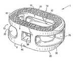
- FIG. 1Ashows a perspective view of an embodiment of the interbody spinal implant having a generally oval shape and roughened surface topography on the top surface;
- FIG. 1Bshows a top view of the first embodiment of the interbody spinal implant illustrated in FIG. 1A ;
- FIG. 2shows a perspective view from the front of another embodiment of the interbody spinal implant according to the invention
- FIG. 3shows a perspective view from the rear of the embodiment of the interbody spinal implant illustrated in FIG. 2 ;
- FIG. 4shows a perspective view from the front of yet another embodiment of the interbody spinal implant according to the invention.
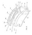
- FIG. 5shows a perspective view from the rear of the embodiment of the interbody spinal implant illustrated in FIG. 4 highlighting an alternative transverse aperture
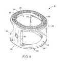
- FIG. 6shows a perspective view of another embodiment of the interbody spinal implant having a generally oval shape and being especially well adapted for use in a cervical spine surgical procedure;
- FIG. 7shows a perspective view of an implant having a generally box shape
- FIG. 8shows an exploded view of a generally oval-shaped implant with an integration plate
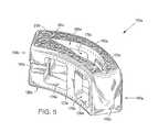
- FIG. 9shows an exploded view of a curved implant with an integration plate
- FIG. 10shows an exploded view of a posterior implant with an integration plate
- FIG. 11shows an exploded view of a lateral lumbar implant with an integration plate
- FIG. 12shows an exploded view of a generally oval-shaped anterior cervical implant with an integration plate
- FIG. 13Ashows an oval-shaped implant positioned on the vertebral endplate
- FIG. 13Bshows an anterior spine perspective of an oval-shaped implant positioned between an upper and lower vertebrae
- FIG. 13Cshows a laterally inserted implant positioned on the vertebral endplate
- FIG. 13Dshows an anterior spine perspective of a laterally inserted implant positioned between an upper and lower vertebrae
- FIG. 13Eshows a top perspective of a cervical implant positioned on the vertebral endplate
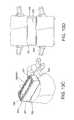
- FIG. 14Ashows a perspective of two posterior inserted implants positioned on the vertebral endplate
- FIG. 14Bshows a top perspective of two posterior inserted implants positioned on the vertebral endplate
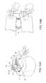
- FIG. 14Cshows a perspective of a single posterior inserted implant positioned at an oblique angle on the vertebral endplate
- FIG. 14Dshows a top perspective of a single posterior inserted implant positioned at an oblique angle on the vertebral endplate
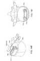
- FIG. 14Eshows a perspective of a transforaminal curved implant positioned proximal to the anterior end of a vertebral endplate
- FIG. 14Fshows a top perspective of a transforaminal curved implant positioned proximal to the anterior end of a vertebral endplate
- FIG. 15Ashows example sizes, areas, and area ratios for one embodiment of an implant
- FIG. 15Bshows example sizes, areas, and area ratios for another embodiment of an implant
- FIG. 15Cshows example sizes, areas, and area ratios for another embodiment of an implant
- FIG. 15Dshows example sizes, areas, and area ratios for another embodiment of an implant
- FIG. 15Eshows example sizes, areas, and area ratios for another embodiment of an implant
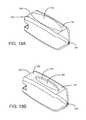
- FIG. 16Ashows a perspective view of an enlarged vertical aperture on an implant
- FIG. 16Bshows a perspective view of an enlarged vertical aperture through an integration plate
- FIG. 17Ashows a top view of an embodiment of a vertical aperture for the implant of FIG. 16 ;
- FIG. 17Bshows a top view of another embodiment of a vertical aperture for the implant of FIG. 16 ;
- FIG. 17Cshows a top view of another embodiment of a vertical aperture for the implant of FIG. 16 ;
- FIG. 17Dshows a top view of another embodiment of a vertical aperture for the implant of FIG. 16 ;
- FIG. 18Ashows a perspective view of an enlarged vertical aperture on another embodiment of an implant
- FIG. 18Bshows a perspective view of an enlarged vertical aperture through an integration plate on another embodiment of an implant
- FIG. 19Ashows a top view of an embodiment of a vertical aperture for the implant of FIG. 18 ;
- FIG. 19Bshows a top view of another embodiment of a vertical aperture for the implant of FIG. 18 ;
- FIG. 19Cshows a top view of another embodiment of a vertical aperture for the implant of FIG. 18 ;
- FIG. 19Dshows a top view of another embodiment of a vertical aperture for the implant of FIG. 18 ;
- FIG. 20Ashows a perspective view of an enlarged vertical aperture on another embodiment of an implant
- FIG. 20Bshows a perspective view of an enlarged vertical aperture through an integration plate on another embodiment of an implant
- FIG. 21Ashows a top view of an embodiment of a vertical aperture for the implant of FIG. 20 ;
- FIG. 21Bshows a top view of another embodiment of a vertical aperture for the implant of FIG. 20 ;
- FIG. 21Cshows a top view of another embodiment of a vertical aperture for the implant of FIG. 20 ;
- FIG. 21Dshows a top view of another embodiment of a vertical aperture for the implant of FIG. 20 ;
- FIG. 22Ashows a perspective view of an enlarged vertical aperture on another embodiment of an implant
- FIG. 22Bshows a perspective view of an enlarged vertical aperture through an integration plate on another embodiment of an implant
- FIG. 23Ashows a top view of an embodiment of a vertical aperture for the implant of FIG. 22 ;
- FIG. 23Bshows a top view of another embodiment of a vertical aperture for the implant of FIG. 22 ;
- FIG. 23Cshows a top view of another embodiment of a vertical aperture for the implant of FIG. 22 ;
- FIG. 23Dshows a top view of another embodiment of a vertical aperture for the implant of FIG. 22 ;
- FIG. 24Ashows a perspective view of an enlarged vertical aperture on another embodiment of an implant
- FIG. 24Bshows a perspective view of an enlarged vertical aperture through an integration plate on another embodiment of an implant
- FIG. 25Ashows a top view of an embodiment of a vertical aperture for the implant of FIG. 24 ;
- FIG. 25Bshows a top view of another embodiment of a vertical aperture for the implant of FIG. 24 ;
- FIG. 25Cshows a top view of another embodiment of a vertical aperture for the implant of FIG. 24 ;
- FIG. 25Dshows a top view of another embodiment of a vertical aperture for the implant of FIG. 24 .
- Certain embodiments of the inventionmay be especially suited for placement between adjacent human vertebral bodies.
- the implants of the inventionmay be used in procedures such as Anterior Lumbar Interbody Fusion (ALIF), Posterior Lumbar Interbody Fusion (PLIF), Transforaminal Lumbar Interbody Fusion (TLIF), and cervical fusion. Certain embodiments do not extend beyond the outer dimensions of the vertebral bodies.
- Interbody spinal implantsallow for improved seating over the apophyseal rim of the vertebral body. Still further, interbody spinal implants, as now taught, better utilize this vital surface area over which fusion may occur and may better bear the considerable biomechanical loads presented through the spinal column with minimal interference with other anatomical or neurological spinal structures. Even further, interbody spinal implants, according to certain aspects of the invention, allow for improved visualization of implant seating and fusion assessment. Interbody spinal implants, as now taught, may also facilitate osteointegration with the surrounding living bone.
- Anterior interbody spinal implants in accordance with certain aspects of the inventioncan be preferably made of a durable material such as stainless steel, stainless steel alloy, titanium, or titanium alloy, but can also be made of other durable materials such as, but not limited to, polymeric, ceramic, and composite materials.
- a durable materialsuch as stainless steel, stainless steel alloy, titanium, or titanium alloy
- other durable materialssuch as, but not limited to, polymeric, ceramic, and composite materials.
- certain embodiments of the inventionmay be comprised of a biocompatible, polymeric matrix reinforced with bioactive fillers, fibers, or both.
- Certain embodiments of the inventionmay be comprised of urethane dimethacrylate (DUDMA)/tri-ethylene glycol dimethacrylate (TEDGMA) blended resin and a plurality of fillers and fibers including bioactive fillers and E-glass fibers.
- Durable materialsmay also consist of any number of pure metals, metal alloys, or both.
- Titanium and its alloysare generally preferred for certain embodiments of the invention due to their acceptable, and desirable, strength and biocompatibility.
- certain embodiments of the present interbody spinal implantmay have improved structural integrity and may better resist fracture during implantation by impact. Interbody spinal implants, as now taught, may therefore be used as a distractor during implantation.
- FIG. 1shows a perspective view of a first embodiment of the interbody spinal implant 1 especially well adapted for use in an ALIF procedure.
- the interbody spinal implant 1includes a body having a top surface 10 , a bottom surface 20 , opposing lateral sides 30 , and opposing anterior 40 and posterior 50 portions.
- One or both of the top surface 10 and the bottom surface 20has a roughened topography 80 .
- the roughened topography 80is distinct from the teeth provided on the surfaces of some conventional devices.
- the interbody spinal implant 1is substantially hollow and has a generally oval-shaped transverse cross-sectional area with smooth, rounded, or both smooth and rounded lateral sides 30 and posterior-lateral corners 52 .
- a substantially hollow implant 1includes an implant 1 having at least about 33% of the interior volume of the implant 1 vacant.
- the implant 1includes at least one vertical aperture 60 that extends the entire height of the implant body.
- implant fixationmay depend, at least in part, on the attachment and proliferation of osteoblasts and like-functioning cells upon the implant surface.
- a surfacemay be bioactive due to its ability to facilitate cellular attachment and osteointegration.
- the surface roughened topography 80may better promote the osteointegration of the implant 1 .
- the surface roughened topography 80may also better grip the vertebral endplate surfaces and inhibit implant migration of the implant 1 upon placement and seating in a patient.
- the implant 1further includes the roughened topography 80 on at least a portion of its top 10 and bottom 20 surfaces for gripping adjacent bone and inhibiting migration of the implant 1 .
- FIG. 1shows roughened topography 80 on an embodiment of the implant 1 .
- the roughened topography 80may be obtained through a variety of techniques including, without limitation, chemical etching, shot peening, plasma etching, laser etching, or abrasive blasting (such as sand or grit blasting).
- the interbody spinal implant 1may be comprised of titanium, or a titanium alloy, having the surface roughened topography 80 .
- the surfaces of the implant 1are preferably bioactive.
- the roughened topography 80is obtained via the repetitive masking and chemical or electrochemical milling processes described in U.S. Pat. No. 5,258,098; U.S. Pat. No. 5,507,815; U.S. Pat. No. 5,922,029; and U.S. Pat. No. 6,193,762.
- Each of these patentsis incorporated in this document by reference.
- the surfaceis prepared through an etching process which utilizes the random application of a maskant and subsequent etching of the metallic substrate in areas unprotected by the maskant. This etching process is repeated a number of times as necessitated by the amount and nature of the irregularities required for any particular application.
- Control of the strength of the etchant material, the temperature at which the etching process takes place, and the time allotted for the etching processallow fine control over the resulting surface produced by the process.
- the number of repetitions of the etching processcan also be used to control the surface features.
- an etchant mixture of nitric acid (HNO 3 ) and hydrofluoric (HF) acidmay be repeatedly applied to a titanium surface to produce an average etch depth of about 0.53 mm.
- Interbody spinal implants 1in accordance with some preferred embodiments of the invention, may be comprised of titanium, or a titanium alloy, having an average surface roughness of about 100 ⁇ m. Surface roughness may be measured using a laser profilometer or other standard instrumentation.
- chemical modification of the titanium implant surfacescan be achieved using HF and a combination of hydrochloric acid and sulfuric acid (HCl/H 2 SO 4 ).
- HFhydrochloric acid and sulfuric acid
- the first exposureis to HF and the second is to HCl/H 2 SO 4 .
- Chemical acid etching alone of the titanium implant surfacehas the potential to greatly enhance osteointegration without adding particulate matter (e.g., hydroxyapatite) or embedding surface contaminants (e.g., grit particles) and this surface can be bioactive, for example, by inducing or supporting bone formation by cellular reactions.
- the implant 1may be shaped to reduce the risk of subsidence, and improve stability, by maximizing contact with the apophyseal rim of vertebral endplates. Embodiments may be provided in a variety of anatomical footprints having a medial-lateral width ranging from about 32 mm to about 44 mm.
- An interbody spinal implant 1generally does not require extensive supplemental or obstructive implant instrumentation to maintain the prepared disc space during implantation.
- the interbody spinal implant 1 and associated implantation methodsallow for larger-sized implants as compared with other size-limited interbody spinal implants known in the art. This advantage allows for greater medial-lateral width and correspondingly greater contact with the apophyseal rim.
- the implant 1may also include an anti-expulsion edge 8 as described in more detail below.
- the implant 1has an opening 90 in the anterior portion 40 .
- the posterior portion 50has a similarly shaped opening 90 .
- only the anterior portion 40has the opening 90 while the posterior portion 50 has an alternative opening 92 (which may have a size and shape different from the opening 90 ).
- the opening 90has a number of functions. One function is to facilitate manipulation of the implant 1 by the caretaker.
- the caretakermay insert a surgical tool into the opening 90 and, through the engagement between the surgical tool and the opening 90 , manipulate the implant 1 .
- the opening 90may be threaded to enhance the engagement.
- the implant 1may further include at least one transverse aperture 70 that extends the entire transverse length of the implant body.
- the at least one transverse aperture 70may provide improved visibility of the implant 1 during surgical procedures to ensure proper implant placement and seating, and may also improve post-operative assessment of implant fusion.
- the substantially hollow area defined by the implant 1may be filled with cancellous autograft bone, allograft bone, DBM, porous synthetic bone graft substitute, BMP, or combinations of these materials (collectively, bone graft materials), to facilitate the formation of a solid fusion column within the spine of a patient.
- Certain embodiments of the inventionare particularly suited for use during interbody spinal implant procedures (or vertebral body replacement procedures) and may act as a final distractor during implantation, thus minimizing the instrument load upon the surgeon.
- the spinemay first be exposed via an anterior approach and the center of the disc space identified.
- the disc spaceis then initially prepared for implant insertion by removing vertebral cartilage.
- Soft tissue and residual cartilagemay then also be removed from the vertebral endplates.
- Vertebral distractionmay be performed using trials of various-sized embodiments of the interbody spinal implant 1 .
- the determinatively sized interbody implant 1may then be inserted in the prepared disc space for final placement.
- the distraction procedure and final insertionmay also be performed under fluoroscopic guidance.
- the substantially hollow area within the implant bodymay optionally be filled, at least partially, with bone fusion-enabling materials such as, without limitation, cancellous autograft bone, allograft bone, DBM, porous synthetic bone graft substitute, BMP, or combinations of those materials.
- bone fusion-enabling materialmay be delivered to the interior of the interbody spinal implant 1 using a delivery device mated with the opening 90 in the anterior portion 40 of the implant 1 .
- the interbody spinal implant 1may be generally larger than those currently known in the art, and therefore have a correspondingly larger hollow area which may deliver larger volumes of fusion-enabling bone graft material.
- the bone graft materialmay be delivered such that it fills the full volume, or less than the full volume, of the implant interior and surrounding disc space appropriately.
- FIG. 1shows a perspective view of one embodiment of the invention, the interbody spinal implant 1 , which is especially well adapted for use in an ALIF procedure.
- Other embodiments of the inventionare better suited for PLIF, TLIF, or cervical fusion procedures.
- FIGS. 2 and 3show perspective views, from the front and rear, respectively, of an embodiment of an interbody spinal implant 101 especially well adapted for use in a PLIF procedure.
- the interbody spinal implant 101includes a body having a top surface 110 , a bottom surface 120 , opposing lateral sides 130 , and opposing anterior 140 and posterior 150 portions.
- One or both of the top surface 110 and the bottom surface 120has a roughened topography 180 for gripping adjacent bone and inhibiting migration of the implant 101 .
- the interbody spinal implant 101are substantially hollow and have a generally rectangular shape with smooth, rounded, or both smooth and rounded lateral sides and anterior-lateral corners.
- the anterior portion 140may have a tapered nose 142 to facilitate insertion of the implant 101 .
- the implant 101has chamfers 106 at the corners of its posterior portion 150 . The chamfers 106 prevent the implant 101 from catching upon insertion, risking potential damage such as severed nerves, while still permitting the implant 101 to have an anti-expulsion edge 108 .
- the implant 101includes at least one vertical aperture 160 that extends the entire height of the implant body.
- the vertical aperture 160further defines a transverse rim 200 .
- the implant 101has an opening 190 in the posterior portion 150 .
- the opening 190has a number of functions. One function is to facilitate manipulation of the implant 101 by the caretaker.
- the caretakermay insert a surgical tool into the opening 190 and, through the engagement between the surgical tool and the opening 190 , manipulate the implant 101 .
- the opening 190may be threaded to enhance the engagement.
- the implant 101may also have an Implant Holding Feature (IHF) 194 instead of or in addition to the opening 190 .
- IHFImplant Holding Feature
- the IHF 194is located proximate the opening 190 in the posterior portion 150 .
- the IHF 194is a U-shaped notch.
- the IHF 194has a number of functions, one of which is to facilitate manipulation of the implant 101 by the caretaker. Other functions of the opening 190 and the IHF 194 are to increase visibility of the implant 101 during surgical procedures and to enhance engagement between bone graft material and adjacent bone.
- the implant 101may further include at least one transverse aperture 170 .
- the size and shape of the transverse aperture 170are carefully chosen (and predetermined) to achieve a preferable design tradeoff for the particular application envisioned for the implant 101 .
- the transverse aperture 170should have minimal dimensions to maximize the strength and structural integrity of the implant 101 .
- the transverse aperture 70should have maximum dimensions to (a) improve the visibility of the implant 101 during surgical procedures to ensure proper implant placement and seating, and to improve post-operative assessment of implant fusion, and (b) to facilitate engagement between bone graft material and adjacent bone.
- the substantially hollow area defined by the implant 101may be filled with bone graft materials to facilitate the formation of a solid fusion column within the spine of a patient.
- the transverse aperture 170extends the entire transverse length of the implant body and nearly the entire height of the implant body. Thus, the size and shape of the transverse aperture 170 approach the maximum possible dimensions for the transverse aperture 170 .
- the transverse aperture 170may be broken into two, separate sections by an intermediate wall 172 .
- the section of the transverse aperture 170 proximate the IHF 194is substantially rectangular in shape; the other section of the transverse aperture 170 has the shape of a curved arch. Other shapes and dimensions are suitable for the transverse aperture 170 . In particular, all edges of the transverse aperture 170 may be rounded, smooth, or both.
- the intermediate wall 172may be made of the same material as the remainder of the implant 101 (e.g., metal), or it may be made of another material (e.g., PEEK) to form a composite implant 101 .
- the intermediate wall 172may offer one or more of several advantages, including reinforcement of the implant 101 and improved bone graft containment.
- FIGS. 2 and 3The embodiment of the invention illustrated in FIGS. 2 and 3 is especially well suited for a PLIF surgical procedure.
- TLIF surgeryis done through the posterior (rear) part of the spine and is essentially like an extended PLIF procedure.
- the TLIF procedurewas developed in response to some of the technical problems encountered with a PLIF procedure.
- the main difference between the two spine fusion proceduresis that the TLIF approach to the disc space is expanded by removing one entire facet joint; a PLIF procedure is usually done on both sides by only taking a portion of each of the paired facet joints.
- the anterior approachin most cases still provides the best visualization, most surface area for healing, and the best reduction of any of the approaches to the disc space.
- These advantagesmust be weighed, however, against the increased morbidity (e.g., unwanted aftereffects and postoperative discomfort) of a second incision.
- Probably the biggest determinate in how the disc space is approachedis the comfort level that the spine surgeon has with an anterior approach for the spine fusion surgery. Not all spine surgeons are comfortable with operating around the great vessels (aorta and vena cava) or have access to a skilled vascular surgeon to help them with the approach. Therefore, choosing one of the posterior approaches for the spine fusion surgery is often a more practical solution.
- FIGS. 4 and 5The embodiment of the invention illustrated in FIGS. 4 and 5 is especially well suited when the spine surgeon elects a TLIF procedure. Many of the features of the implant 101 a illustrated in FIGS. 4 and 5 are the same as those of the implant 101 illustrated in FIGS. 2 and 3 . Therefore, these features are given the same reference numbers, with the addition of the letter “a,” and are not described further.
- the implant 101 ahas a curved shape.
- the chamfers 106 and anti-expulsion edge 108 of the implant 101are replaced by curves or rounded edges for the implant 101 a .
- the TLIF procedureoften permits use of a larger implant 101 a which, in turn, may affect the size and shape of the predetermined vertical aperture 160 a.
- the substantially constant 9 mm width of the transverse rim 200 of the implant 101is replaced with a larger, curved transverse rim 200 a .
- the width of the transverse rim 200 ais 9 mm in the regions adjacent the anterior 140 a and posterior 150 a portions. That width gradually increases to 11 mm, however, near the center of the transverse rim 200 a .
- the additional real estate provided by the transverse rim 200 aallows the shape of the vertical aperture 160 a to change, in cross section, from approximating a football to approximating a boomerang.
- the implant 101 amay also have a lordotic angle to facilitate alignment.
- the lateral side 130 a depicted at the top of the implant 101 ais preferably generally greater in height than the opposing lateral side 130 a . Therefore, the implant 101 a may better compensate for the generally less supportive bone found in certain regions of the vertebral endplate.
- the transverse aperture 170 aextends the entire transverse length of the implant body and nearly the entire height of the implant body.
- FIG. 5highlights an alternative transverse aperture 170 a .
- the transverse aperture 170 ais broken into two, separate sections by an intermediate wall 172 a .
- the dimensions of the transverse aperture 170 a shown in FIG. 5are much smaller than those for the transverse aperture 170 a shown in FIG. 4 .
- the two sections of the alternative transverse aperture 170 aare each illustrated as substantially rectangular in shape and extending nearly the entire height of the implant body; other sizes and shapes are possible for one or both sections of the alternative transverse aperture 170 a.
- the intermediate wall 172 amay be made of the same material as the remainder of the implant 101 a (e.g., metal), or it may be made of another material (e.g., PEEK) to form a composite implant 101 a . It is also possible to extend the intermediate wall 172 a , whether made of metal, PEEK, ultra-high molecular weight polyethylene (UHMWPE), or another material, to eliminate entirely the transverse aperture 170 a . Given the reinforcement function of the intermediate wall 172 a , the length of the vertical aperture 160 a can be extended (as shown in FIG. 5 ) beyond the top surface 110 a and into the anterior portion 140 a of the implant 101 a.
- UHMWPEultra-high molecular weight polyethylene
- the top surface 110 a of the implant 101 aneed not include the roughened topography 180 a . This difference permits the implant 101 a , at least for certain applications, to be made entirely of a non-metal material. Suitable materials of construction for the implant 101 a of such a design (which would not be a composite) include PEEK, hedrocel, UHMWPE, other radiolucent soft plastics, and additional materials as would be known to an artisan.
- the discsare usually not very large.
- the space available for the nervesis also not that great, however, which means that even a small cervical disc herniation may impinge on the nerve and cause significant pain.
- the implant 201is generally smaller in size than the other implant embodiments.
- the lower mechanical load requirements imposed by the cervical applicationtypically render a composite implant unnecessary. Therefore, the implant 201 is generally made entirely of metal (e.g., titanium) and devoid of other materials (e.g., PEEK).
- the implant 201includes a body having a top surface 210 , a bottom surface 220 , opposing lateral sides 230 , and opposing anterior 240 and posterior 250 portions.
- One or both of the top surface 210 and the bottom surface 220has a roughened topography 280 for gripping adjacent bone and inhibiting migration of the implant 201 .
- the implant 201is substantially hollow and has a generally oval shape with smooth, rounded, or both smooth and rounded edges.
- the implant 201includes at least one vertical aperture 260 that extends the entire height of the implant body.
- the vertical aperture 260further defines a transverse rim 300 .
- the implant 201has an opening 290 in the posterior portion 250 .
- the opening 290has a number of functions. One function is to facilitate manipulation of the implant 201 by the caretaker.
- the caretakermay insert a surgical tool into the opening 290 and, through the engagement between the surgical tool and the opening 290 , manipulate the implant 201 .
- the opening 290may be threaded to enhance the engagement.
- the implant 201may further include at least one transverse aperture 270 .
- the size and shape of the transverse aperture 270are carefully chosen (and predetermined) to achieve a preferable design tradeoff for the particular application envisioned for the implant 201 .
- the transverse aperture 270may extend the entire transverse length of the implant body and nearly the entire height of the implant body.
- the size and shape of the transverse aperture 270approach the maximum possible dimensions for the transverse aperture 270 .
- the implant 201may be provided with a solid rear wall 242 .
- the rear wall 242extends the entire width of the implant body and nearly the entire height of the implant body. Thus, the rear wall 242 essentially closes the anterior portion 240 of the implant 201 .
- the rear wall 242may offer one or more of several advantages, including reinforcement of the implant 201 and improved bone graft containment. In the cervical application, it may be important to prevent bone graft material from entering the spinal canal.
- the implant 201may have a generally box shape which gives the implant 201 increased cortical bone coverage.
- the implant 201 shown in FIG. 7has a curved transverse rim 300 in the area of the anterior portion 240 .
- the shape of the posterior portion 250 of the implant 201is substantially flat, however, and the shape of the transverse rim 300 in the area of the posterior portion 250 is substantially square.
- the posterior portion 250provides a face that can receive impact from a tool, such as a surgical hammer, to force the implant 201 into position.
- the implant 201may also have a lordotic angle to facilitate alignment. As illustrated in FIGS. 6 and 7 , the anterior portion 240 is preferably generally greater in height than the posterior portion 250 . Therefore, the implant 201 may better compensate for the generally less supportive bone found in certain regions of the vertebral endplate. As an example, four degrees of lordosis may be built into the implant 201 to help restore balance to the spine.
- the implant 1 , 101 , 101 a , and 201are generally shaped (i.e., made wide) to maximize contact with the apophyseal rim of the vertebral endplates. They are designed to be impacted between the endplates, with fixation to the endplates created by an interference fit and annular tension.
- the implants 1 , 101 , 101 a , and 201are shaped and sized to spare the vertebral endplates and leave intact the hoop stress of the endplates.
- a wide range of sizesare possible to capture the apophyseal rim, along with a broad width of the peripheral rim, especially in the posterior region. It is expected that such designs will lead to reduced subsidence. As much as seven degrees of lordosis (or more) may be built into the implants 1 , 101 , 101 a , and 201 to help restore cervical balance.
- endplate-sparing spinal implant 1 , 101 , 101 a , and 201When endplate-sparing spinal implant 1 , 101 , 101 a , and 201 seats in the disc space against the apophyseal rim, it should still allow for deflection of the endplates like a diaphragm. This means that, regardless of the stiffness of the spinal implant 1 , 101 , 101 a , and 201 , the bone graft material inside the spinal implant 1 , 101 , 101 a , and 201 receives load, leading to healthy fusion. The vertical load in the human spine is transferred though the peripheral cortex of the vertebral bodies.
- the natural biomechanicsmay be better preserved than for conventional devices. If this is true, the adjacent vertebral bodies should be better preserved by the implant 1 , 101 , 101 a , and 201 , hence reducing the risk of adjacent segment issues.
- the dual-acid etched roughened topography 80 , 180 , 180 a , and 280 of the top surface 30 , 130 , 130 a , and 230 and the bottom surface 40 , 140 , 140 a , and 240 along with the broad surface area of contact with the end-plates,is expected to yield a high pull-out force in comparison to conventional designs.
- a pull-out strength of up to 3,000 ntmay be expected.
- the roughened topography 80 , 180 , 180 a , and 280creates a biological bond with the end-plates over time, which should enhance the quality of fusion to the bone.
- the in-growthstarts to happen much earlier than the bony fusion.
- the center of the implant 1 , 101 , 101 a , and 201remains open to receive bone graft material and enhance fusion. Therefore, it is possible that patients might be able to achieve a full activity level sooner than for conventional designs.
- the spinal implant 1 , 101 , 101 a , and 201 according to the inventionoffers several advantages relative to conventional devices.
- Such conventional devicesinclude, among others, ring-shaped cages made of allograft bone material, threaded titanium cages, and ring-shaped cages made of PEEK or carbon fiber.
- the implant 1 , 101 , 101 a , and 201includes an integration plate 82 , 182 , 182 a , and 282 , for example, as shown in FIG. 8A-FIG . 10 and FIG. 12 .
- a lateral implant 301 having a substantially rectangular shapemay include an integration plate 382 , for example, as shown in FIG. 11 .
- the lateral implant 301comprises the same general features as the implant 1 , 101 , 101 a , and 201 , including a top surface 310 , a bottom surface 320 , lateral sides 330 , opposing anterior 340 and posterior 350 portions, an opening 390 , as well as at least one vertical aperture 360 that extends the entire height of the implant body, and one or more transverse apertures 370 that extend the entire transverse length of the implant body.
- the integration plateshown in the drawings as component 82 ( FIG. 8A and FIG. 8B ), 182 ( FIG. 10 ), 182 a ( FIG. 9 ), 382 ( FIG. 11 ), and 282 ( FIG. 12 ), respectively, includes the roughened surface topography 80 , 180 , 180 a , 280 , and 380 , and is connectable to either or both of the top surface 10 , 110 , 110 a , 210 , and 310 or bottom surface 20 , 120 , 120 a , 220 , and 320 .
- the integration plate 82 , 182 , 182 a , 282 , and 382includes a top surface 81 , 181 , 181 a , 281 , and 381 ; a bottom surface 83 , 183 , 183 a , 283 , and 383 ; an anterior portion 41 , 141 , 141 a , 241 , and 341 ; a posterior portion 51 , 151 , 151 a , 251 , and 351 ; and at least one vertical aperture 61 , 161 , 161 a , 261 , and 361 .
- the anterior portion 41 , 141 , 141 a , 241 , and 341preferably aligns with the anterior portion 40 , 140 , 140 a , 240 , and 340 of the main body of the implant 1 , 101 , 101 a , 201 , and 301 , respectively, and the posterior portion 51 , 151 , 151 a , 251 , and 351 aligns with the posterior portion 50 , 150 , 150 a , 250 , and 350 of the main body of the implant 1 , 101 , 101 a , 201 , and 301 , respectively.
- the vertical aperture 61 , 161 , 161 a , 261 , and 361preferably aligns with the vertical aperture 60 , 160 , 160 a , 260 , and 360 of the main body of the implant 1 , 101 , 101 a , 201 , and 301 , respectively.
- the integration plate vertical aperture 61 , 161 , 161 a , 261 , and 361 and the body vertical aperture 60 , 160 , 160 a , 260 , and 360preferably comprise substantially the same shape.
- the top surface 81 , 181 , 181 a , 281 , and 381 of the integration plate 82 , 182 , 182 a , 282 , and 382preferably comprises the roughened topography 80 , 180 , 180 a , 280 , and 380 .
- the bottom surface 83 , 183 , 183 a , 283 , and 383 of the integration plate 82 , 182 , 182 a , 282 , and 382preferably comprises a reciprocal connector structure, such as a plurality of posts 84 , 184 , 184 a , 284 , and 384 that align with and insert into a corresponding connector structure such as a plurality of holes 12 , 112 , 112 a , 212 , and 312 on the top surface 10 , 110 , 110 a , 210 , and 310 and/or bottom surface 20 , 120 , 120 a , 220 , and 320 of the main body of the implant 1 , 101 , 101 a , 201 , and 301 , respectively, and thus facilitate the connection between the integration plate 82 , 182 , 182 a , 282 , and 382 and the main body of the implant 1 , 101 , 101 a , 201 ,
- integration plates 82 , 182 , 182 a , 282 , and 382 with different sizes, shapes, or featuresmay be used in connection with the implant 1 , 101 , 101 a , 201 , and 301 , for example, to accommodate attributes of the spine of the patient to which the implant 1 , 101 , 101 a , 201 , and 301 is to be implanted.
- these different sizes, shapes, and featuresare lordotic angles; anti-expulsion edges 8 , 108 , 108 a , 208 , and 308 ; and anti-expulsion angles as described throughout this specification.
- the implant 1 , 101 , 101 a , 201 , and 301is configured to receive the integration plate 82 , 182 , 182 a , 282 , and 382 , respectively.
- the top surface 10 , 110 , 110 a , 210 , and 310 and/or bottom surface 20 , 120 , 120 a , 220 , and 320 of the implant 1 , 101 , 101 a , 201 , and 301may be recessed, and comprise a plurality of holes 12 , 112 , 112 a , 212 , and 312 that mate with the plurality of posts 84 , 184 , 184 a , 284 , and 384 on the bottom surface 83 , 183 , 183 a , 283 , and 383 of the integration plate 82 , 182 , 182 a , 282 , and 382 .
- FIG. 8A and FIG. 8Bshow that the top surface 10 is recessed and comprises a plurality of holes 12 , but the recessed bottom surface 20 and its holes 12 are not shown.
- FIG. 9shows that the top surface 110 a is recessed and comprises a plurality of holes 112 a , but the recessed bottom surface 120 a and its holes 112 a are not shown.
- FIG. 10shows that the top surface 110 is recessed and comprises a plurality of holes 112 , but the recessed bottom surface 120 and its holes 112 are not shown.
- FIG. 11shows that the top surface 310 is recessed and comprises a plurality of holes 312 , but the recessed bottom surface 320 and its holes 312 are not shown.
- top surface 210is recessed and comprises a plurality of holes 212 , but the recessed bottom surface 220 and its holes 212 are not shown.
- the recessmay be at a depth D, and the recess depth D preferably is uniform throughout the top surface 10 , 110 , 110 a , 210 , and 310 and/or bottom surface 20 , 120 , 120 a , 220 , and 320 .
- the recess depth Dpreferably corresponds to a thickness T of the integration plate 82 , 182 , 182 a , 282 , and 382 .
- the depth D and thickness Tare the same so that once the integration plate 82 , 182 , 182 a , 282 , and 382 and body of the implant 1 , 101 , 101 a , 201 , and 301 , respectively, are placed together, the top surface 10 , 110 , 110 a , 210 , and 310 and/or bottom surface 20 , 120 , 120 a , 220 , and 320 of the implant 1 , 101 , 101 a , 201 , and 301 is substantially even, at least at the seam/junction between the integration plate 82 , 182 , 182 a , 282 , and 382 and the top surface 10 , 110 , 110 a , 210 , and 310 or bottom surface 20 , 210 , 120 a , 2
- the posterior portion 51 , 151 , 151 a , 251 , and 351 and the anterior portion 41 , 141 , 141 a , 241 , and 341 of the integration plate 82 , 182 , 182 a , 282 , and 382have different thicknesses such that the anterior portion 41 , 141 , 141 a , 241 , and 341 has a greater thickness than the thickness T of the posterior portion 51 , 151 , 151 a , 251 , and 351 .
- the recess depth D, the thickness T, and the thickness T′may each independently be from about 0.1 mm to about 10 mm. In preferred aspects, the recess depth D, the thickness T, and the thickness T′ may each independently be from about 1 mm to about 5 mm.
- either the recess depth D, the thickness T, and the thicknessmay be selected from about 0.1 mm, about 0.25 mm, about 0.5 mm, about 0.75 mm, about 1 mm, about 1.25 mm, about 1.5 mm, about 1.75 mm, about 2 mm, about 2.25 mm, about 2.5 mm, about 2.75 mm, about 3 mm, about 3.25 mm, about 3.5 mm, about 3.75 mm, about 4 mm, about 4.25 mm, about 4.5 mm, about 4.75 mm, about 5 mm, about 5.5 mm, about 6 mm, about 6.5 mm, about 7 mm, about 75 mm, or about 8 mm.
- Recessing the top surface 10 , 110 , 110 a , 210 , and 310 or bottom surface 20 , 120 , 120 a , 220 , and 320exposes a ridge 11 , 111 , 111 a , 211 , and 311 against which the anterior portion 41 , 141 , 141 a , 241 , and 341 , posterior portion 51 , 151 , 151 a , 251 , and 251 or lateral side of the integration plate 82 , 182 , 182 a , 282 , and 382 may be seated when brought together with the implant 1 , 101 , 101 a , 201 , and 301 .
- the integration plate 82 , 182 , 182 a , 282 , and 382may be used with an implant suitable for ALIF (e.g., implant 1 , integration plate 82 ), PLIF (e.g., implant 101 , integration plate 182 ), or TLIF fusion (e.g., implant 101 a , integration plate 182 a ); may be used with an implant suitable for cervical fusion (e.g., implant 201 , integration plate 282 ); and may be used with an implant suitable for lateral lumbar insertion (e.g., implant 301 , integration plate 382 ).
- ALIFe.g., implant 1 , integration plate 82
- PLIFe.g., implant 101 , integration plate 182
- TLIF fusione.g., implant 101 a , integration plate 182 a
- an implant suitable for cervical fusione.g., implant 201 , integration plate 282
- the integration plate 82 , 182 , 182 a , 282 , and 382is preferably metal, and may be used with a metal implant.
- the metal integration plate 82 , 182 , 182 a , 282 , and 382may also be used with a molded plastic or polymer implant, or a composite implant.
- the integration plate 82 , 182 , 182 a , 282 , and 382may also comprise a plastic, polymeric, or composite material.
- the reciprocal connectorsuch as the post 84 , 184 , 184 a , 284 , and 384 preferably is secured within the connector of the body such as the hole 12 , 112 , 112 a , 212 , and 312 to mediate the connection between the integration plate 82 , 182 , 182 a , 282 , and 382 and the implant 1 , 101 , 101 a , 201 , and 301 .
- the connectionshould be capable of withstanding significant loads and shear forces when implanted in the spine of the patient.
- connection between the post 84 , 184 , 184 a , 284 , and 384 and the hole 12 , 112 , 112 a , 212 , and 312may comprise a friction fit.
- an adhesivemay be used to further strengthen any of the integration plate 82 , 182 , 182 a , 282 , and 382 and implant 1 , 101 , 101 a , 201 , and 301 connections.
- An adhesivemay comprise a cement, glue, polymer, epoxy, solder, weld, or other suitable binding material.
- Vertebraecomprise a high density, cortical bone exterior that surrounds a low density and highly porous cancellous bone core.
- Cortical boneis part of the vertebral endplate surface, and a disc occupies the space between opposing vertebral endplate surfaces (e.g., the intervertebral space).
- Movement, including walking, lifting, stretching, and other activities that implicate movement and flexing of the spineproduce load forces that impact disc material, and also induce flexing and compression of the vertebral endplate surfaces.
- the cortical bone of the vertebral endplate surfacemay flex inward toward the core of the vertebrae or outward toward the disc in the intervertebral space.
- Load forces and vertebral endplate bone flexing under load forcesmay be taken into account in terms of the configuration of the implant 1 , 101 , 101 a , 201 , and 301 .
- a goalis to balance the amount of surface area of the implant 1 , 101 , 101 a , 201 , and 301 that contacts vertebral endplate surfaces so that the spine is adequately supported under load forces and stresses with the amount of surface area of bone graft material used in conjunction with the implant 1 , 101 , 101 a , 201 , and 301 to facilitate integration of the implant 1 , 101 , 101 a , 201 , and 301 and new bone growth.
- the top surface 10 , 110 , 110 a , 210 , and 310 and/or bottom surface 20 , 120 , 120 a , 220 , and 320make contact with the vertebral endplate bone, and surround the vertical aperture 60 , 160 , 160 a , 260 , and 360 into which a bone graft material is preferably placed and housed during implantation.
- the bone graft materialalso makes contact with the vertebral endplate bone.
- portions of the top surface 10 , 110 , 110 a , 210 , and 310 and/or bottom surface 20 , 120 , 120 a , 220 , and 320 and/or bone graft materialbear at least a fraction of the load forces and stresses of the spine where the implant is placed.
- the total load force or stressis not necessarily borne equally by the implant surfaces and the bone graft material, and is not necessarily distributed equally about the top surface 10 , 110 , 110 a , 210 , and 310 and/or bottom surface 20 , 120 , 120 a , 220 , and 320 of the implant 1 , 101 , 101 a , 201 , and 301 ; certain sections, or subsections of the implant 1 , 101 , 101 a , 201 , and 301 may bear a higher share of the load force relative to other sections.
- the bone graft material and the vertebral endplate bonemay be taken into account.
- Other factorssuch as the type of vertebrae between which the implant 1 , 101 , 101 a , 201 , and 301 is/will be implanted (e.g., cervical, thoracic, lumbar), the specific vertebrae (e.g., L-1/L-2 versus L-5/S-1) between which the implant 1 , 101 , 101 a , 201 , and 301 is/will be implanted, the location where the implant 1 , 101 , 101 a , 201 , and 301 is/will be seated in the intervertebral space, the size, shape, and configuration of the implant 1 , 101 , 101 a , 201 , and 301 itself (including the dimensions, shape, and location of the vertical aperture 60
- the practitionermay position the implant 1 , 101 , 101 a , 201 , and 301 in the intervertebral space at a loci where bone graft material exposed through the vertical aperture 60 , 160 , 160 a , 260 , and 360 may make maximal contact with vertebral endplate bone, whether at rest/under normal conditions, or under particular load stress.
- the practitionermay also position the implant 1 , 101 , 101 a , 201 , and 301 in the intervertebral space at a loci where a higher amount of the load stress will be borne by the posterior, anterior, or lateral portion of the top surface 10 , 110 , 110 a , 210 , and 310 and/or bottom surface 20 , 120 , 120 a , 220 , and 320 .
- FIG. 13Ashows the placement of the implant 1 in the intervertebral space (upper vertebrae not shown) on top of the apophyseal rim of the lower vertebrae endplate such that posterior portion 50 of the implant 1 is positioned proximal to the posterior edge of the endplate.
- FIG. 13Ashows the placement of the implant 1 in the intervertebral space (upper vertebrae not shown) on top of the apophyseal rim of the lower vertebrae endplate such that posterior portion 50 of the implant 1 is positioned proximal to the posterior edge of the end
- FIG. 13Bshows an anterior view of the example in FIG. 13A , with the implant 1 between the upper and lower vertebrae.
- FIG. 13Cshows the placement of the implant 301 in the intervertebral space (upper vertebrae not shown) on top of the apophyseal rim of the lower vertebrae endplate such that a lateral side 330 of the implant 301 is positioned proximal to the posterior edge of the endplate and the anterior 340 and posterior 350 portions of the implant 301 are positioned laterally.
- FIG. 13Dshows an anterior view of the example in FIG. 13C , with the implant 301 between the upper and lower vertebrae.
- the practitionermay include two implants 101 in the intervertebral space (upper vertebrae not shown).
- the posterior portion 150 of each implant 101faces the posterior edge of the endplate.
- the implants 101may be positioned substantially parallel relative to each other, or may be positioned at any suitable angle relative to each other.
- the arrowsillustrate the direction in which the implant 101 was inserted in a PLIF procedure.
- a single implant 101may be positioned at an oblique angle off of the anterior-posterior direction of the vertebrae, for example, as shown in FIG. 14C and FIG. 14D .
- a single implant 101 a that has a curved profilemay be positioned proximal to the anterior edge of the vertebral endplate, as shown in FIGS. 14E and 14F .
- the curvature of the implant 101may approximate the curvature of the vertebral endplate.
- the implant 101 amay also be positioned proximal to the posterior edge of the vertebral endplate (not shown) or proximate to one of the lateral sides of the vertebral endplate (not shown).
- the implant 101 amay also be positioned more toward the center of the vertebral endplate, and less toward one of the edges of the vertebral endplate.
- the implant 101 amay also be positioned at an oblique angle off of the anterior-posterior direction of the vertebrae.
- the shape and configuration of the implant 1 , 101 , 101 a , 201 , and 301 itselfmay facilitate the goal of balancing the amount of surface area of the implant 1 , 101 , 101 a , 201 , and 301 and the amount of surface area of bone graft material that contact vertebral endplate bone.
- the vertical aperture 60 , 160 , 160 a , 260 , and 360may be lengthened and/or widened and/or positioned in different locations about the top surface 10 , 110 , 110 a , 210 , and 310 and/or bottom surface 20 , 120 , 120 a , 220 , and 320 .
- the vertical aperture 60 , 160 , 160 a , 260 , and 360may be positioned substantially in the center of the body of the implant 1 , 101 , 101 a , 201 , and 301 , or may be positioned off-center, such as toward the anterior 40 , 140 , 140 a , 240 , and 340 , or the posterior 50 , 150 , 150 a , 250 , and 350 , or one of the lateral sides 30 , 130 , 130 a , 230 , and 330 .
- the dimensions and location of the vertical aperture 60 , 160 , 160 a , 260 , and 360may be based on the insertion path of the implant 1 , 101 , 101 a , 201 , and 301 and/or the final location and orientation in the disc space.
- the dimensions and location of the vertical aperture 60 , 160 , 160 a , 260 , and 360may also be based on the frictional characteristics of the roughened surface topography 80 , 180 , 180 a , 280 , and 380 .
- the shape of the vertical aperture 60 , 160 , 160 a , 260 , and 360may be varied.
- the shapemay be substantially circular, elliptical, or D-shaped.
- the anterior, posterior, or lateral sides of the circle, ellipse, or D-shapemay bow outward (e.g., a rhomboid oval) or inward (e.g., hourglass shape).
- the shapemay also include straight edges, including a substantially diamond, triangular, rectangular, quadrilateral, or polygonal shape, including a star shape.
- the shapemay comprise an irregular shape or form.
- the particular shapemay be based on the insertion path of the implant 1 , 101 , 101 a , 201 , and 301 and/or the final location and orientation in the disc space.
- the shape of the vertical aperture 60 , 160 , 160 a , 260 , and 360may also be based on the frictional characteristics of the roughened surface topography 80 , 180 , 180 a , 280 , and 380 .
- the shape, dimensions and location of the vertical aperture 61 , 160 , 160 a , 260 , and 360may be based on the insertion path of the implant 1 , 101 , 101 a , 201 , and 301 and/or the final location and orientation in the disc space.
- the shape, dimensions and location of the vertical aperture 60 , 160 , 160 a , 260 , and 360may be based on the insertion path of the implant 1 , 101 , 101 a , 201 , and 301 , and/or the final location and orientation in the disc space, and/or the frictional characteristics of the roughened surface topography 80 , 180 , 180 a , 280 , and 380 .
- the implant 1 , 101 , 101 a , 201 , and 301comprises an integration plate 82 , 182 , 182 a , 282 , and 382 on either or both of the top surface 10 , 110 , 110 a , 210 , and 310 and bottom surface 20 , 120 , 120 a , 220 , and 320 , having a vertical aperture 61 , 161 , 161 a , 261 , and 361 .
- the bone graft materialis loaded into the vertical aperture 61 , 161 , 161 a , 261 , and 361 of the integration plate 82 , 182 , 182 a , 282 , and 382 and the vertical aperture 60 , 160 , 160 a , 260 , and 360 of the implant 1 , 101 , 101 a , 201 , and 301 .
- bone graft material housed in the implant 1 , 101 , 101 a , 201 , and 301may extend through the implant vertical aperture 60 , 160 , 160 a , 260 , and 360 and through the integration plate vertical aperture 61 , 161 , 161 a , 261 , and 361 .
- the surface of the graft materialmay thus establish, and preferably maintain, contact the vertebral endplate bone.
- the integration plate vertical aperture 61 , 161 , 161 a , 261 , and 361may be lengthened and/or widened and/or positioned in different locations about the top surface 81 , 181 , 181 a , 281 , and 381 and/or bottom surface 83 , 183 , 183 a , 283 , and 383 .
- the vertical aperture 61 , 161 , 161 a , 261 , and 361may be positioned substantially in the center of the integration plate 82 , 182 , 182 a , 282 , and 382 , or may be positioned off-center, such as toward the anterior 41 , 141 , 141 a , 241 , and 341 , or the posterior 51 , 151 , 151 a , 251 , and 351 , or one of the lateral sides of the integration plate 82 , 182 , 182 a , 282 , and 382 .
- the dimensions and location of the vertical aperture 61 , 161 , 161 a , 261 , and 361may be based on the insertion path of the implant 1 , 101 , 101 a , 201 , and 301 and/or the final location and orientation in the disc space.
- the dimensions and location of the vertical aperture 61 , 161 , 161 a , 261 , and 361may also be based on the frictional characteristics of the roughened surface topography 80 , 180 , 180 a , 280 , and 380 .
- the shape of the integration plate vertical aperture 61 , 161 , 161 a , 261 , and 361may be varied.
- the shapemay be substantially circular, elliptical, or D-shaped.
- the anterior, posterior, or lateral sides of the circle, ellipse, or D-shapemay bow outward (e.g., a rhomboid oval) or inward (e.g., hourglass shape).
- the shapemay also include straight edges, including a substantially diamond, triangular, rectangular, quadrilateral, or polygonal shape, including a star shape.
- the shapemay comprise an irregular shape or form.
- the particular shapemay be based on the insertion path of the implant 1 , 101 , 101 a , 201 , and 301 and/or the final location and orientation in the disc space.
- the shape of the vertical aperture 61 , 161 , 161 a , 261 , and 361may also be based on the frictional characteristics of the roughened surface topography 80 , 180 , 180 a , 280 , and 380 .
- the shape, dimensions and location of the vertical aperture 61 , 161 , 161 a , 261 , and 361may be based on the insertion path of the implant 1 , 101 , 101 a , 201 , and 301 and/or the final location and orientation in the disc space.
- the shape, dimensions and location of the vertical aperture 61 , 161 , 161 a , 261 , and 361may be based on the insertion path of the implant 1 , 101 , 101 a , 201 , and 301 , and/or the final location and orientation in the disc space, and/or the frictional characteristics of the roughened surface topography 80 , 180 , 180 a , 280 , and 380 .
- the implant vertical aperture 60 , 160 , 160 a , 260 , and 360preferably aligns with the integration plate vertical aperture 61 , 161 , 161 a , 261 , and 361 .
- each implant body vertical aperture 60 , 160 , 160 a , 260 , and 360 and integration plate vertical aperture 61 , 161 , 161 a , 261 , and 361preferably has substantially the same length, substantially the same width, substantially the same shape, and substantially the same location on their respective surfaces.
- the integration plate vertical aperture 61 , 161 , 161 a , 261 , and 361may be longer and/or wider and/or positioned differently than its implant vertical aperture 60 , 160 , 160 a , 260 , and 360 counterpart.
- the vertical aperture 60 , 160 , 160 a , 260 , and 360may be narrower in terms of length and width relative to the integration plate vertical aperture 61 , 161 , 161 a , 261 , and 361 (which are comparatively larger) such that the graft material occupies a wider surface area at its top or bottom relative to the center mass.
- Such a configurationmay be desirable for purposes of using less bone graft material by lessening the inner volume of the implant 1 , 101 , 101 a , 201 , and 301 to be filled with bone graft material.
- the surface area of the bone graft material that will ultimately contact vertebral endplate boneis maximized (because the integration plate vertical aperture 61 , 161 , 161 a , 261 , and 361 has a larger berth), while the amount of bone graft material that does not contact vertebral endplate bone, but rather occupies space in the voids of the implant 1 , 101 , 101 a , 201 , and 301 , is minimized (because the implant vertical aperture 60 , 160 , 160 a , 260 , and 360 has a smaller berth).
- the inner volume of the implant 1 , 101 , 101 a , 201 , and 301may comprise a “V” shape, or an “X” or hourglass shape.
- One or more of the anterior 40 , 140 , 140 a , 240 , and 340 edges, posterior 50 , 150 , 150 a , 250 , and 350 edges, and lateral side 30 , 130 , 130 a , 230 , and 330 edges of the implantmay be rounded or tapered (see, e.g., FIG. 1A-FIG . 7 ).
- the rounding or taperingis preferably present on at least the insertion face of the implant 1 , 101 , 101 a , 201 , and 301 .
- the rounding or taperingmay facilitate insertion of the implant 1 , 101 , 101 a , 201 , and 301 by lessening friction or the possibility of snagging vertebral endplate bone as the implant 1 , 101 , 101 a , 201 , and 301 is placed and positioned in the intervertebral space.
- the rounding or taperingmay help to avoid snagging or damaging blood vessels and nerves in and around the insertion site.
- the implant vertical aperture 60 , 160 , 160 a , 260 , and 360comprises dimensions and a shape, and defines a transverse rim 100 (implant 1 ), 200 (implant 101 ), 200 a (implant 101 a ), 300 (implant 201 ), and 400 (implant 301 ).
- the integration plate vertical aperture 61 , 161 , 161 a , 261 , and 361comprises dimensions and a shape, and defines an integration plate transverse rim 86 (implant 1 ), 186 (implant 101 ), 186 a (implant 101 a ), 286 (implant 201 ), and 386 (implant 301 ).
- the transverse rim 100 , 200 , 200 a , 300 , and 400is also defined by the position of the implant vertical aperture 60 , 160 , 160 a , 260 , and 360 or the integration plate vertical aperture 61 , 161 , 161 a , 261 , and 361 (e.g., centered, toward the anterior edge, toward the posterior edge, or toward one of the lateral edges) on the top surface 10 , 110 , 110 a , 210 , and 310 , the bottom surface 20 , 120 , 120 a , 220 , and 320 , or the integration plate top surface 81 , 181 , 181 a , 281 , and 381 .
- the implant vertical aperture 60 , 160 , 160 a , 260 , and 360or the integration plate vertical aperture 61 , 161 , 161 a , 261 , and 361 (e.g., centered, toward the anterior edge, toward the posterior edge, or toward one of the
- Each transverse rim 100 , 200 , 200 a , 300 , and 400 and integration plate transverse rim 86 , 186 , 186 a , 286 , and 386comprise a posterior portion having a posterior portion width P, an anterior portion having an anterior portion width A, and a first lateral section having a first lateral side width L, and a second lateral section having a second lateral side width L′.
- the posterior portion width Pmay comprise the distance between the posterior edge of the implant 1 , 101 , 101 a , 201 , and 301 or posterior edge of the integration plate 82 , 182 , 182 a , 282 , and 382 and the posterior edge of the implant vertical aperture 61 , 161 , 161 a , 261 , and 361 or the integration plate vertical aperture 60 , 160 , 160 a , 260 , and 360 .
- the transverse rim 100 , 200 , 200 a , 300 , and 400 or the transverse rim of the integration plate 86 , 186 , 186 a , 286 , and 386effectively surrounds the vertical aperture 60 , 160 , 160 a , 260 , and 360 or 61 , 161 , 161 a , 261 , and 361 , respectively.
- the transverse rim 100 , 200 , 200 a , 300 , and 400may be present on the top surface 10 , 110 , 110 a , 210 , and 310 and the bottom surface 20 , 120 , 120 a , 220 , and 320 of the implant 1 , 101 , 101 a , 201 , and 301 .
- the transverse rim of the integration plate 86 , 186 , 186 a , 286 , and 386may be present on the top surface 81 , 181 , 181 a , 281 , and 381 of the integration plate 82 , 182 , 182 a , 282 , and 382 .
- the top surface 81 , 181 , 181 a , 281 , and 381is the surface that is exposed and visible, and may make contact with vertebral endplate bone.
- the top surface 81 , 181 , 181 a , 281 , and 381 of an integration plate 82 , 182 , 182 a , 282 , and 382 that occupies the bottom portion 20 , 120 , 120 a , 220 , and 320is the bottom-most surface of the implant 1 , 101 , 101 a , 201 , and 301 .
- the top surface of the bottom integration plateis effectively the bottom surface of the implant.
- the configuration of the implant vertical aperture 60 , 160 , 160 a , 260 , and 360 and/or the integration plate vertical aperture 61 , 161 , 161 a , 261 , and 361(e.g., the shape, dimensions, and position on the top or bottom surface) and the transverse rim 100 , 200 , 200 a , 300 , and 400 defined by the aperture shape, dimensions, and position distributes the spine load force (e.g., the downward force/stress that is produced by movement of vertebrae from walking, lifting, moving, stretching, pushing, pulling, sitting, standing, jumping, laying supine, etc.) about the implant 1 , 101 , 101 a , 201 , and 301 .
- the spine load forcee.g., the downward force/stress that is produced by movement of vertebrae from walking, lifting, moving, stretching, pushing, pulling, sitting, standing, jumping, laying supine, etc.
- the load forcemay change and/or shift to different sections of the implant 1 , 101 , 101 a , 201 , and 301 (e.g., posterior, anterior, or one of the lateral sides) depending on the type and/or direction of movement by the patient, as well as the level of exertion underlying the movement, among other things.
- a configuration of the implant 1 , 101 , 101 a , 201 , and 301may take into account the condition of the patient, including the sex, age, weight, the presence or absence of spinal defects, diseases, or disorders, and potential activity, potential types of movement, and potential levels of exertion.
- a given configurationmay cause distribution of the spine load force to be shifted to a greater extent to the posterior portion of the transverse rim 100 , 200 , 200 a , 300 , and 400 relative to the anterior portion, or vice versa, or may cause distribution of the spine load force to be shifted to a greater extent to the first lateral section relative to the second lateral section, or vice versa, and the degree of shifting may depend on the type and/or direction of movement by the patient, as well as the level of exertion underlying the movement.
- the spine load forcemay also be distributed to the area that approximates the junction of the anterior or posterior portions with the first or second lateral sections of the transverse rim 100 , 200 , 200 a , 300 , and 400 .
- the configurationcauses the spine load force to be distributed evenly about the transverse rim 100 , 200 , 200 a , 300 , and 400 , and as a result, bone graft material disposed in the implant vertical aperture 60 , 160 , 160 a , 260 , and 360 and/or the integration plate vertical aperture 61 , 161 , 161 a , 261 , and 361 may also bear an even amount of the spine load force.
- the configurationcauses the spine load force to be distributed unevenly about the transverse rim 100 , 200 , 200 a , 300 , and 400 such that one or more of the subsections (e.g., the posterior portion, anterior portion, first lateral section, second lateral section, or junction/approximate junction thereof) bear a greater amount of the load force than other sections.
- the subsectionse.g., the posterior portion, anterior portion, first lateral section, second lateral section, or junction/approximate junction thereof
- the apportionment of the spine load forcemay be in part a function of the configuration, in part a function of the placement (location, orientation, number of implants, etc.) of the implant 1 , 101 , 101 a , 201 , 301 in the intervertebral space, and in part the type and/or direction of movement by the patient, as well as the level of exertion underlying the movement.
- the apportionmentmay be controlled by the practitioner selecting the most appropriate configuration to apportion the spine load force in a desired manner, and by the practitioner selecting the most appropriate placement of the implant 1 , 101 , 101 a , 201 , and 301 in the intervertebral space.
- the amount of spine load force distributed to a given section or subsection of the transverse rim 100 , 200 , 200 a , 300 , and 400 and/or bone graft material disposed in the implant vertical aperture 60 , 160 , 160 a , 260 , and 360 and/or the integration plate vertical aperture 61 , 161 , 161 a , 261 , and 361may be about 1% to about 100%.
- about 40% of the spine load forcemay be apportioned to the posterior section of the transverse rim 100 , 200 , 200 a , 300 , and 400
- about 60% of the spine load forcemay be apportioned to the anterior section of the transverse rim 100 , 200 , 200 a , 300 , and 400 , when the patient in which the implant 1 , 101 , 101 a , 201 , and 301 is implanted is standing upright with substantially good posture, for example, with substantially a neutral spine position.
- the amount of spine load force distributed to a given section or subsection of the transverse rim 100 , 200 , 200 a , 300 , and 400(e.g., anterior rim, posterior rim, or a lateral side of the rim) and/or bone graft material disposed in the implant vertical aperture 60 , 160 , 160 a , 260 , and 360 and/or the integration plate vertical aperture 61 , 161 , 161 a , 261 , and 361 may independently be about 10% to about 20%, about 10% to about 30%, about 10% to about 50%, about 10%, to about 60%, about 10%, to about 70%, about 10%, to about 80%, about 10% to about 90%, about 15% to about 55%, about 15% to about 75%, about 20% to about 30%, about 20% to about 60%, about 20% to about 70%, about 20% to about 80%, about 20% to about 90%, about 25% to about 60%, about 25% to about 75%, about 25% to about 85%, about 30% to about 50%, about 30% to about 70%, about 30% to about 80%
- the amount of spine load force distributed to a given section or subsection of the transverse rim 100 , 200 , 200 a , 300 , and 400 and/or bone graft material disposed in the implant vertical aperture 60 , 160 , 160 a , 260 , and 360 and/or the integration plate vertical aperture 61 , 161 , 161 a , 261 , and 361may independently be about 5%, about 10%, about 15%, about 20%, about 25%, about 30%, about 35%, about 40%, about 45%, about 50%, about 55%, about 60%, about 65%, about 70%, about 75%, about 80%, about 85%, about 90%, about 95%, or more of the load force when the patient in which the implant 1 , 101 , 101 a , 201 , and 301 is implanted is standing upright with substantially good posture/substantially a neutral spine position.
- the amount of distributed spine load forcemay also (e.g., in addition to the patient standing upright with substantially good posture) be a function of where the implant 1 , 101 , 101 a , 201 , and 301 is positioned on the vertebral endplate.
- the amount of distributed spine load forcemay be a function of where and how the implant 1 , 101 , 101 a , 201 , and 301 is positioned on the vertebral endplate.
- the implant 1 , 101 , 101 a , 201 , and 301may be positioned substantially in the center of the vertebral endplate, may be positioned substantially at an anterior edge of the vertebral endplate, may be positioned proximal to an anterior edge of the vertebral endplate, may be positioned substantially at a posterior edge of the vertebral endplate, may be positioned proximal to a posterior edge of the vertebral endplate, may be positioned substantially at a lateral edge of the vertebral endplate, or may be positioned proximal to a lateral edge of the vertebral endplate.
- anterior/posterior edge of the implant 1 , 101 , 101 a , 201 , and 301may be positioned substantially parallel to the anterior to posterior line of the vertebrae
- anterior/posterior edge of the implant 1 , 101 , 101 a , 201 , and 301may be positioned substantially perpendicular to the anterior to posterior line of the vertebrae
- anterior/posterior edge of the implant 1 , 101 , 101 a , 201 , and 301may be positioned at an angle oblique to the anterior to posterior line of the vertebrae.
- the anterior section of the transverse rim 100 , 200 , 200 a , 300 , and 400may bear about 60% to 80% of the spine load force when the patient in which the implant 1 , 101 , 101 a , 201 , and 301 is implanted is standing upright with substantially good posture/substantially a neutral spine position, but when the same implant 1 , 101 , 101 a , 201 , and 301 is positioned substantially at the center of the vertebral endplate, the anterior section of the transverse rim 100 , 200 , 200 a , 300 , and 400 may bear about 40% to about 60% of the spine load force when the patient in which the implant 1 , 101 , 101 a , 201 , and 301 is implanted is standing upright with substantially good posture/substantially a neutral spine position.
- the posterior portion width Pmay be about 1 mm to about 15 mm, about 1 mm to about 7 mm, about 1 mm to about 6 mm, about 1 mm to about 5 mm, about 1 mm to about 4 mm, about 1 mm to about 3 mm, about 2 mm to about 6 mm, about 2 mm to about 5 mm, about 2 mm to about 4 mm, about 2 mm to about 3 mm, about 3 mm to about 8 mm, about 3 mm to about 7 mm, about 3 mm to about 6 mm, about 4 mm to about 7 mm, about 4 mm to about 6 mm, about 5 to about 7 mm, or about 5 mm to about 6 mm.
- the posterior portion width Pmay be about 1 mm, about 2 mm, about 3 mm, about 4 mm, about 5 mm, about 6 mm, about 7 mm, about 8 mm, about 9 mm, about 10 mm, about 11 mm, about 12 mm, about 13 mm, about 14 mm, or about 15 mm.
- the anterior portion width Amay be about 1 mm to about 15 mm, about 1 mm to about 8 mm, about 1 mm to about 7 mm, about 1 mm to about 6 mm, about 1 mm to about 5 mm, about 1 mm to about 4 mm, about 1 mm to about 3 mm, about 2 mm to about 10 mm, about 2 mm to about 9 mm, about 2 mm to about 8 mm, about 2 mm to about 7 mm, about 2 mm to about 6 mm, about 2 mm to about 5 mm, about 2 mm to about 4 mm, about 2 mm to about 3 mm, about 3 mm to about 10 mm, about 3 mm to about 9 mm, about 3 mm to about 8 mm, about 3 mm to about 7 mm, about 3 mm to about 6 mm, about 3 mm to about 5 mm, about 4 mm to about 9 mm, about 4 mm to about 8 mm, about 4 mm to about 7 mm, about 4 mm to about 6
- the anterior portion width Amay be about 1 mm, about 2 mm, about 3 mm, about 4 mm, about 5 mm, about 6 mm, about 7 mm, about 8 mm, about 9 mm, about 10 mm, about 11 mm, about 12 mm, about 13 mm, about 14 mm, or about 15 mm.
- the first lateral side width L and second lateral side width L′may each independently be about 1 mm to about 10 mm, about 1 mm to about 9 mm, about 1 mm to about 8 mm, about 1 mm to about 7 mm, about 1 mm to about 6 mm, about 1 mm to about 5 mm, about 1 mm to about 4 mm, about 1 mm to about 3 mm, about 2 mm to about 10 mm, about 2 mm to about 9 mm, about 2 mm to about 8 mm, about 2 mm to about 7 mm, about 2 mm to about 6 mm, about 2 mm to about 5 mm, about 2 mm to about 4 mm, about 2 mm to about 3 mm, about 3 mm to about 10 mm, about 3 mm to about 9 mm, about 3 mm to about 8 mm, about 3 mm to about 7 mm, about 3 mm to about 6 mm, about 3 mm to about 5 mm, about 3 mm to about 4 mm, about 4 mm to
- first lateral side width L and second lateral side width L′may each independently be about 1 mm, about 2 mm, about 3 mm, about 4 mm, about 5 mm, about 6 mm, about 7 mm, about 8 mm, about 9 mm, or about 10 mm.
- the posterior portion width P, anterior portion width A, first lateral side width L, and second lateral side width L′may have the same size relative to each other, or may have a different size relative to each other.
- the anterior portion width Adecreases and the posterior portion width increases, relative to a comparable implant 1 , 101 , 101 a , 201 , and 301 in which the vertical aperture 60 , 160 , 160 a , 260 , and 360 is centered, and vice versa.
- the first lateral side width L(e.g., the side to which the vertical aperture 60 , 160 , 160 a , 260 , and 360 is positioned closest) decreases and the second lateral side width increases, relative to a comparable implant 1 , 101 , 101 a , 201 , and 301 in which the vertical aperture 60 , 160 , 160 a , 260 , and 360 is centered, and vice versa.
- the integration plate vertical aperture 61 , 161 , 161 a , 261 , and 361the integration plate vertical aperture 61 , 161 , 161 a , 261 , and 361 .
- the posterior portion width P, anterior portion width A, and/or first and second lateral side width L and L′may allow for better stress sharing between the implant 1 , 101 , 101 a , 201 , and 301 and the adjacent vertebral endplates, and helps to compensate for the weaker posterior endplate bone.
- the transverse rim 100 , 200 , 200 a , 300 , and 400has a generally large surface area and contacts the vertebral endplate.
- the transverse rim 100 , 200 , 200 a , 300 , and 400may act to better distribute contact stresses upon the implant 1 , 101 , 101 a , 201 , and 301 , and minimize the risk of subsidence while maximizing contact with the apophyseal supportive bone.
- the posterior portion width P, anterior portion width A, and/or first and second lateral side width L and L′comprise dimensions of the implant top surface 10 , 110 , 110 a , 210 , and 310 , the implant bottom surface 20 , 120 , 120 a , 220 , and 320 , and/or the integration plate top surface 81 , 181 , 181 a , 281 , and 381 .
- the implant top surface 10 , 110 , 110 a , 210 , and 310 , the implant bottom surface 20 , 120 , 120 a , 220 , and 320 , and/or the integration plate top surface 81 , 181 , 181 a , 281 , and 381may be about 5 mm to about 50 mm in width, and in some aspects may be about 7 mm to about 15 mm, about 8 mm to about 12 mm, about 9 mm to about 12 mm, about 9 mm to about 11 mm, about 10 mm to about 20 mm, about 10 mm to about 18 mm, about 10 mm to about 17 mm, about 11 mm to about 19 mm, about 11 mm to about 17 mm, about 12 mm to about 17 mm, about
- the implant top surface 10 , 110 , 110 a , 210 , and 310 , the implant bottom surface 20 , 120 , 120 a , 220 , and 320 , and/or the integration plate top surface 81 , 181 , 181 a , 281 , and 381may be about 9 mm, about 10 mm, about 11 mm, about 12 mm, about 13 mm, about 14 mm, about 15 mm, about 16 mm, about 17 mm, about 18 mm, about 19 mm, about 20 mm, about 21 mm, about 22 mm, about 25 mm, about 30 mm, about 31 mm, about 32 mm, about 33 mm, about 34 mm, about 35 mm, about 36 mm, about 37 mm, about 38 mm
- the implant top surface 10 , 110 , 110 a , 210 , and 310 , the implant bottom surface 20 , 120 , 120 a , 220 , and 320 , and/or the integration plate top surface 81 , 181 , 181 a , 281 , and 381may be about 10 mm to about 70 mm in length, and in some aspects may be about 10 mm to about 20 mm, about 10 mm to about 18 mm, about 11 mm to about 19 mm, about 11 mm to about 18 mm, about 11 mm to about 17 mm, about 12 mm to about 16 mm, about 18 mm to about 34 mm, about 18 mm to about 32 mm, about 20 mm to about 34 mm, about 20 mm to about 32 mm, about 20 mm to about 34 mm, about 20 mm to about 32 mm, about 20 mm to about 34 mm, about 20 mm to about 32 mm, about 20 mm to about 34 mm, about 20 mm to about 32
- the implant top surface 10 , 110 , 110 a , 210 , and 310 , the implant bottom surface 20 , 120 , 120 a , 220 , and 320 , and/or the integration plate top surface 81 , 181 , 181 a , 281 , and 381may be about 9 mm, about 10 mm, about 11 mm, about 12 mm, about 13 mm, about 14 mm, about 15 mm, about 16 mm, about 17 mm, about 18 mm, about 19 mm, about 20 mm, about 21 mm, about 22 mm, about 23 mm, about 24 mm, about 25 mm, about 26 mm, about 27 mm, about 28 mm, about 29 mm, about 30 mm, about 31 mm, about 35 mm, about 40 mm
- the size and shape of the vertical aperture 60 , 160 , 160 a , 260 , and 360 , as well as the integration plate vertical aperture 61 , 161 , 161 a , 261 , and 361are carefully chosen to achieve a preferable design tradeoff for the particular application envisioned for the implant 1 , 101 , 101 a , 201 , and 301 .
- the vertical aperture 60 , 160 , 160 a , 260 , and 360 or integration plate vertical aperture 61 , 161 , 161 a , 261 , and 361preferably maximizes the surface area of the top surface 10 , 110 , 110 a , 210 , and 310 , integration plate top surface 81 , 181 , 181 a , 281 , and 381 , and/or bottom surface 20 , 120 , 120 a , 220 , and 320 , while at the same time maximizing both the capacity for radiographic visualization and access to the bone graft material. It is highly preferred that the bone graft material bear at least some of the load forces of the spine once the implant 1 , 101 , 101 a , 201 , and 301 is implanted.
- the vertical aperture 60 , 160 , 160 a , 260 , and 360 , and the integration plate vertical aperture 61 , 161 , 161 a , 261 , and 361each preferably comprises a maximum width at its center.
- the width of the vertical aperture 60 , 160 , 160 a , 260 , and 360 , and the integration plate vertical aperture 61 , 161 , 161 a , 261 , and 361may range from about 20% to about 80% of the distance between opposing lateral sides. In some aspects, the width ranges from about 40% to about 80% of the distance between the opposing lateral sides. In some aspects, the width ranges from about 50% to about 70% of the distance between the opposing lateral sides.
- the widthranges from about 50% to about 65% of the distance between the opposing lateral sides. In some aspects, the width ranges from about 60% to about 70% of the distance between the opposing lateral sides. In some aspects, the width ranges from about 55% to about 75% of the distance between the opposing lateral sides. In some aspects, the width ranges from about 60% to about 80% of the distance between the opposing lateral sides. In some aspects, the width is about 40%, about 45%, about 50%, about 55%, about 60%, about 65%, about 70%, about 75%, about 80%, about 85%, or about 90% of the distance between the opposing lateral sides.
- the width of the vertical aperture 60 , 160 , 160 a , 260 , and 360 , or the integration plate vertical aperture 61 , 161 , 161 a , 261 , and 361comprises the dimension between the lateral sides.
- the length of the vertical aperture 60 , 160 , 160 a , 260 , and 360 , and the integration plate vertical aperture 61 , 161 , 161 a , 261 , and 361may range from about 20% to about 80% of the distance between the anterior and posterior edges. In some aspects, the length ranges from about 40% to about 80% of the distance between the anterior and posterior edges. In some aspects, the length ranges from about 50% to about 70% of the distance between the anterior and posterior edges. In some aspects, the length ranges from about 50% to about 65% of the distance between the anterior and posterior edges. In some aspects, the length ranges from about 60% to about 70% of the distance between the anterior and posterior edges.
- the lengthranges from about 55% to about 75% of the distance between the anterior and posterior edges. In some aspects, the length ranges from about 60% to about 80% of the distance between the anterior and posterior edges. In some aspects, the length is about 40%, about 45%, about 50%, about 55%, about 60%, about 65%, about 70%, about 75%, about 80%, about 85%, or about 90% of the distance between the anterior and posterior edges.
- the length of the vertical aperture 60 , 160 , 160 a , 260 , and 360 , or the integration plate vertical aperture 61 , 161 , 161 a , 261 , and 361comprises the dimension between the anterior and posterior edges.
- the size of the length and the size of the width of the vertical aperture 60 , 160 , 160 a , 260 , and 360 , or the integration plate vertical aperture 61 , 161 , 161 a , 261 , and 361may vary independently of each other.
- the surface area of the implant top surface 10 , 110 , 110 a , 210 , and 310 , and the implant bottom surface 20 , 120 , 120 a , 220 , and 320 , including the integration plate top surface 81 , 181 , 181 a , 281 , and 381may comprise the roughened surface topography 80 , 180 , 180 a , 280 , and 380 (contact surface), the area comprising rounded or tapered edges, if rounded or tapered edges are present, and the area occupied by the vertical aperture 60 , 160 , 160 a , 260 , and 360 , or the integration plate vertical aperture 61 , 161 , 161 a , 261 , and 361 .
- the area of the foot printmay be about 120 mm 2 to about 1200 mm 2 .
- the area of the foot printmay be about 130 mm 2 to about 235 mm 2 , about 137 mm 2 to about 233 mm 2 , about 180 mm 2 to about 320 mm 2 , about 182 mm 2 to about 316 mm 2 , about 182 mm 2 to about 315 mm 2 , about 225 mm 2 to about 340 mm 2 , about 229 mm 2 to about 338 mm 2 , about 230 mm 2 to about 340 mm 2 , about 570 mm 2 to about 1130 mm 2 , about 575 mm 2 to about 925 mm 2 , about 577 mm 2 to about 924 mm 2 , about 575 mm 2 to about 1125 mm 2 , or about 578 mm 2 to about 1123 mm 2 .
- the area of the foot printmay be about 135 mm 2 , about 137 mm 2 , about 180 mm 2 , about 181 mm 2 , about 182 mm 2 , about 218 mm 2 , about 220 mm 2 , about 229 mm 2 , about 230 mm 2 , about 233 mm 2 , about 280 mm 2 , about 283 mm 2 , about 300 mm 2 , about 31 mm 2 , about 316 mm 2 , about 337 mm 2 , about 338 mm 2 , about 575 mm 2 , about 577 mm 2 , about 578 mm 2 , about 660 mm 2 , about 661 mm 2 , about 662 mm 2 , about 700 mm 2 , about 707 mm 2 , about 708 mm 2 , about 740 mm 2 , about 741 mm 2 , about 815 mm 2 , about 816 mm 2 , about 820 mm 2 , about 8
- the area of the contact surfacemay be about 60 mm 2 to about 600 mm 2 .
- the area of the contact surfacemay be about 40 mm 2 to about 140 mm 2 , about 45 mm 2 to about 135 mm 2 , about 50 mm 2 to about 130 mm 2 , about 60 mm 2 to about 125 mm 2 , about 60 mm 2 to about 121 mm 2 , about 60 mm 2 to about 150 mm 2 , about 60 mm 2 to about 140 mm 2 , about 65 mm 2 to about 135 mm 2 , about 65 mm 2 to about 145 mm 2 , about 75 mm 2 to about 132 mm 2 , about 90 mm 2 to about 135 mm 2 , about 95 mm 2 to about 130 mm 2 , about 100 mm 2 to about 125 mm 2 , about 100 mm 2 to about 150 mm 2 , about 104 mm 2 to about 121 mm 2 , about 150 mm 2 to about 240 mm 2 , about 240
- the area of the contact surfacemay be about 60 mm 2 , about 61 mm 2 , about 65 mm 2 , about 70 mm 2 , about 75 mm 2 , about 76 mm 2 , about 80 mm 2 , about 85 mm 2 , about 88 mm 2 , about 89 mm 2 , about 90 mm 2 , about 100 mm 2 , about 104 mm 2 , about 105 mm 2 , about 110 mm 2 , about 120 mm 2 , about 121 mm 2 , about 125 mm 2 , about 128 mm 2 , about 129 mm 2 , about 130 mm 2 , about 131 mm 2 , about 132 mm 2 , about 135 mm 2 , about 250 mm 2 , about 252 mm 2 , about 253 mm 2 , about 260 mm 2 , about 264 mm 2 , about 265 mm 2 , about 285 mm 2 , about 289 mm 2 , about
- the area of the vertical aperture 60 , 160 , 160 a , 260 , and 360 or integration plate vertical aperture 61 , 161 , 161 a , 261 , and 361may be about 20 mm 2 to about 600 mm 2 .
- the area of the vertical aperture 60 , 160 , 160 a , 260 , and 360 or integration plate vertical aperture 61 , 161 , 161 a , 261 , and 361may be about 15 mm 2 to about 90 mm 2 , about 20 mm 2 to about 75 mm 2 , about 20 mm 2 to about 80 mm 2 , about 24 mm 2 to about 72 mm 2 , about 35 mm 2 to about 95 mm 2 , about 40 mm 2 to about 100 mm 2 , about 40 mm 2 to about 90 mm 2 , about 45 mm 2 to about 90 mm 2 , about 45 mm 2 to about 130 mm 2 , about 47 mm 2 to about 86 mm 2 , about 50 mm 2 to about 150 mm 2 , about 50 mm 2 to about 120 mm 2 , about 52 mm 2 to about 117 mm 2 , about 53 mm 2 to about 117 mm 2 , about 150 mm 2 to about 200 mm 2 , about 170 mm
- the area of the vertical aperture 60 , 160 , 160 a , 260 , and 360 or integration plate vertical aperture 61 , 161 , 161 a , 261 , and 361may be about 20 mm 2 , about 25 mm 2 , about 35 mm 2 , about 45 mm 2 , about 47 mm 2 , about 50 mm 2 , about 52 mm 2 , about 53 mm 2 , about 65 mm 2 , about 66 mm 2 , about 70 mm 2 , about 72 mm 2 , about 80 mm 2 , about 82 mm 2 , about 85 mm 2 , about 86 mm 2 , about 115 mm 2 , about 117 mm 2 , about 180 mm 2 , about 182 mm 2 , about 215 mm 2 , about 218 mm 2 , about 270 mm 2 , about 272 mm 2 , about 284 mm 2 , about 285 mm 2 , about 286 mm 2 , about
- the implant 1 , 101 , 101 a , 201 , and 301may be configured according to certain ratios of, for example, the area of the vertical aperture to the area of the foot print (aperture:foot print), or the area of the contact surface to the area of the foot print (contact surface:foot print). Examples of areas, and area ratios for an implant 1 , 101 , 101 a , 201 , and 301 or integration plate 82 , 182 , 182 a , 282 , and 382 are shown in FIG. 15A through FIG. 15E .
- the aperture:foot print ratiomay be about 10% to about 60%.
- the aperture:foot print ratiomay be about 5% to about 30%, about 10% to about 25%, about 10% to about 30%, about 10% to about 35%, about 13% to about 23%, about 15% to about 35%, about 15% to about 40%, about 20% to about 25%, about 20% to about 30%, about 20% to about 55%, about 20% to about 60%, about 25% to about 50%, about 25% to about 55%, about 30% to about 50%, about 30% to about 60%, about 30% to about 65%, about 30% to about 45%, about 31% to about 45%, about 35% to about 55%, about 38% to about 51%, about 40% to about 55%, about 40% to about 60%, about 45% to about 55%, about 47% to about 52%, or about 50% to about 60%.
- the aperture:foot print ratiomay be about 10%, about 11%, about 12%, about 13%, about 14%, about 15%, about 16%, about 17%, about 18%, about 19%, about 20%, about 21%, about 22%, about 23%, about 24%, about 25%, about 26%, about 27%, about 28%, about 29%, about 30%, about 31%, about 32%, about 33%, about 34%, about 35%, about 36%, about 37%, about 38%, about 39%, about 40%, about 41%, about 42%, about 43%, about 44%, about 45%, about 46%, about 47%, about 48%, about 49%, about 50%, about 51%, about 52%, about 53%, about 54%, about 55%, about 58%, about 60%, about 63%, about 65%, about 70%, about 75%, or about 80%.
- the contact surface:foot print ratiomay be about 20% to about 60%.
- the contact surface:foot print ratiomay be about 30% to about 60%, about 32% to about 45%, about 35% to about 50%, about 35% to about 45%, about 40% to about 45%, about 40% to about 42%, about 40% to about 60%, about 45% to about 55%, or about 47% to about 54%.
- the contact surface:foot print ratiomay be about 30%, about 31%, about 32%, about 33%, about 34%, about 35%, about 36%, about 37%, about 38%, about 39%, about 40%, about 41%, about 42%, about 43%, about 44%, about 45%, about 46%, about 47%, about 48%, about 49%, about 50%, about 51%, about 52%, about 53%, about 54%, about 55%, about 56%, about 57%, about 58%, about 59%, or about 60%.
- the drawingsshow examples different possible sizes, shapes, and positions of the vertical aperture 60 , 160 , 160 a , 260 , and 360 and integration plate vertical aperture 61 , 161 , 161 a , 261 , and 361 .
- the drawingssimply illustrate various configurations, and are not to be considered limiting in any way.
- FIG. 16Ashows the vertical aperture 60 and the top surface 10 of the implant 1
- FIG. 16Bshows the vertical aperture 61 and the top surface 81 of the integration plate 82
- the vertical aperture 60 , 61may comprise any suitable shape, dimensions, and position on the implant 1 .
- FIG. 17shows the vertical aperture 60 , 61 substantially in the center of the implant 1 .
- FIG. 17Bshows the vertical aperture 60 , 61 with a wider length and width such that the posterior portion width P, anterior portion width A, first lateral side width L, and second lateral side width L′ are diminished relative to the embodiment shown in FIG. 17A .
- FIG. 17Cshows an example of the vertical aperture 60 , 61 positioned to a lateral side of the implant 1 .
- FIG. 17Dshows an example of the vertical aperture 60 , 61 having a wider length and width, and positioned nearer to the anterior portion 40 of the implant 1 .
- FIG. 18Ashows the vertical aperture 160 and the top surface 110 of the implant 101
- FIG. 18Bshows the vertical aperture 161 and the top surface 181 of the integration plate 182
- the length and width of the vertical aperture 160may be enlarged such that the vertical aperture 160 spans most of the surface area of the top surface 110 ( FIG. 18A ), or the vertical aperture 161 may be positioned toward the anterior portion 140 ( FIG. 18B ).
- Such configurationsin addition to other possible configurations, are shown from a top perspective in FIGS. 19A-19D . For example, FIG.
- FIG. 19Ashows the vertical aperture 160 , 161 substantially in the center of the implant 101 , though the anterior-most edge of the aperture 160 , 161 is positioned more toward the anterior edge of the roughened surface topography 180 of the top surface 110 .
- FIG. 19Bshows the enlarged vertical aperture 160 , 161 that is also positioned nearer to the posterior portion 150 .
- FIG. 19Cshows a vertical aperture 160 , 161 having a smaller profile that is positioned proximate to the posterior portion 150 .
- FIG. 19Dshows a vertical aperture 160 , 161 having a smaller profile that is positioned nearer to the a lateral side 130 .
- FIGS. 20 and 21illustrate different shapes and dimensions of the vertical aperture 160 a and 161 a of the implant 101 a .
- FIG. 20Ashows the vertical aperture 160 a and the top surface 110 a of the implant 101 a
- FIG. 20Bshows the vertical aperture 161 a and the top surface 181 a of the integration plate 182 a .
- the implant 101 acurves, and the vertical aperture 160 a and 161 a has curved edges as well, it is not necessary the outer arc of the implant 101 a curve and aperture 160 a and 161 a lateral curves are identical.
- the shape of the implant 101 a and the shape of the vertical aperture 160 a and 161 amay be independent of each other.
- FIG. 21Ashows the vertical aperture 160 a , 161 a substantially in the center of the implant 101 a , though the anterior-most edge of the aperture 160 a , 161 a is positioned more toward the anterior edge of the roughened surface topography 180 a of the top surface 110 a .
- FIG. 21Bshows the enlarged vertical aperture 160 a , 161 a that is also positioned nearer to the posterior portion 150 a .
- FIG. 21Cshows a vertical aperture 160 a , 161 a having a smaller profile that is positioned proximate to the posterior portion 150 a .
- FIG. 21Dshows a vertical aperture 160 a , 161 a having a smaller profile that is positioned nearer to the a lateral side 130 a.
- FIG. 22Ashows an embodiment of the implant 201 and its vertical aperture 260 and top surface 210
- FIG. 22Bshows the vertical aperture 261 and the top surface 281 of the integration plate 282
- FIG. 23Ashows the vertical aperture 260 , 261 substantially in the center of the implant 201
- FIG. 23Bshows the vertical aperture 260 , 261 positioned nearer to the second lateral side
- FIG. 23Cshows a wider vertical aperture 260 , 261 positioned substantially in the center of the implant 201
- FIG. 23Dshows the vertical aperture 260 , 261 positioned nearer to the posterior portion 250 .
- FIG. 24Ashows the vertical aperture 360 and the top surface 310 of the implant 301
- FIG. 24Bshows the vertical aperture 361 and the top surface 381 of the integration plate 382 .
- the vertical aperture 360 and 361is positioned substantially in the center of the implant 301 .
- the centered configurationis shown from a top perspective in FIG. 25A .
- FIG. 25Bshows the vertical aperture 360 , 361 positioned nearer to the anterior portion 350 .
- FIG. 25Cshows the vertical aperture 360 , 361 positioned proximate to a lateral side 330 .
- FIG. 25Dshows an enlarged vertical aperture 360 , 361 positioned substantially in the center of the implant 301 .
- the disc spacemay be accessed using a standard mini open retroperitoneal laparotomy approach.
- the center of the disc spaceis located by AP fluoroscopy taking care to make sure the pedicles are equidistant from the spinous process.
- the disc spaceis then incised by making a window in the annulus for insertion of certain embodiments of the spinal implant 1 (a 32 or 36 mm window in the annulus is typically suitable for insertion).
- the process according to the inventionminimizes, if it does not eliminate, the cutting of bone.
- the endplatesare cleaned of all cartilage with a curette, however, and a size-specific rasp (or broach) may then be used.
- a rasppreferably substantially minimizes or eliminates removal of bone, thus substantially minimizing or eliminating impact to the natural anatomical arch, or concavity, of the vertebral endplate while preserving much of the apophyseal rim.
- Preservation of the anatomical concavityis particularly advantageous in maintaining biomechanical integrity of the spine. For example, in a healthy spine, the transfer of compressive loads from the vertebrae to the spinal disc is achieved via hoop stresses acting upon the natural arch of the endplate. The distribution of forces, and resultant hoop stress, along the natural arch allows the relatively thin shell of subchondral bone to transfer large amounts of load.
- the vertebral endplate natural archmay be significantly removed due to excessive surface preparation for implant placement and seating. This is especially common where the implant is to be seated near the center of the vertebral endplate or the implant is of relatively small medial-lateral width. Breaching the vertebral endplate natural arch disrupts the biomechanical integrity of the vertebral endplate such that shear stress, rather than hoop stress, acts upon the endplate surface. This redistribution of stresses may result in subsidence of the implant into the vertebral body.
- interbody spinal implant 1 , 101 , 101 a , 201 , and 301include smooth, rounded, and highly radiused posterior portions and lateral sides which may minimize extraneous bone removal for endplate preparation and reduce localized stress concentrations.
- interbody surgical implant 1 , 101 , 101 a , 201 , and 301 and methods of using itare particularly useful in preserving the natural arch of the vertebral endplate and minimizing the chance of implant subsidence.
- endplatesare spared during the process of inserting the spinal implant 1 , 101 , 101 a , 201 , and 301 .
- Spared endplatesallow the transfer of axial stress to the apophasis. Endplate flexion allows the bone graft placed in the interior of the spinal implant 1 to accept and share stress transmitted from the endplates.
- spared endplatesminimize the concern that BMP might erode the cancellous bone.
- interbody spinal implant 1 , 101 , 101 a , 201 , and 301may maintain a position between the vertebral endplates due, at least in part, to resultant annular tension attributable to press-fit surgical implantation and, post-operatively, improved osteointegration at the top surface 10 , 110 , 110 a , 210 , and 310 ; the bottom surface 20 , 120 , 120 a , 220 , and 320 ; or both surfaces.
- Implant systems and methodstension the vertebral annulus via distraction. These embodiments and methods may also restore spinal lordosis, thus improving sagittal and coronal alignment.
- Implant systems currently known in the artrequire additional instrumentation, such as distraction plugs, to tension the annulus. These distraction plugs require further tertiary instrumentation, however, to maintain the lordotic correction during actual spinal implant insertion. If tertiary instrumentation is not used, then some amount of lordotic correction may be lost upon distraction plug removal.
- Interbody spinal implant 1is particularly advantageous in improving spinal lordosis without the need for tertiary instrumentation, thus reducing the instrument load upon the surgeon. This reduced instrument load may further decrease the complexity, and required steps, of the implantation procedure.
- spinal implant 1 , 101 , 101 a , 201 , and 301may also reduce deformities (such as isthmic spondylolythesis) caused by distraction implant methods.
- Traditional implant systemsrequire secondary or additional instrumentation to maintain the relative position of the vertebrae or distract collapsed disc spaces.
- interbody spinal implant 1 , 101 , 101 a , 201 , and 301may be used as the final distractor and thus maintain the relative position of the vertebrae without the need for secondary instrumentation.
- Certain embodimentscollectively comprise a family of implants, each having a common design philosophy. These implants and the associated surgical technique have been designed to address at least the ten, separate challenges associated with the current generation of traditional anterior spinal fusion devices listed above in the Background section of this document.
- Embodiments of the inventionallow end-plate preparation with custom-designed rasps. These rasps preferably have a geometry matched with the geometry of the implant.
- the raspsconveniently remove cartilage from the endplates and remove minimal bone, only in the postero-lateral regions of the vertebral end-plates. It has been reported in the literature that the end-plate is the strongest in postero-lateral regions.
- embodiments of the inventionfirst adequately distract the disc space by inserting (through impaction) and removing sequentially larger sizes of very smooth distractors, which have been size matched with the size of the available implant 1 , 101 , 101 a , 201 , and 301 . Once adequate distraction is achieved, the surgeon prepares the end-plate with a rasp. There is no secondary instrumentation required to keep the disc space distracted while the implant 1 , 101 , 101 a , 201 , and 301 is inserted, as the implant 1 , 101 , 101 a , 201 , and 301 has sufficient mechanical strength that it is impacted into the disc space.
- the height of the implant 1 , 101 , 101 a , 201 , and 301is preferably about 1 mm greater than the height of the rasp used for end-plate preparation, to create some additional tension in the annulus by implantation, which creates a stable implant construct in the disc space.
- the implant geometryhas features which allow it to be implanted via any one of an anterior, antero-lateral, or lateral approach, providing tremendous intra-operative flexibility of options.
- the implant 1 , 101 , 101 a , 201 , and 301has adequate strength to allow impact.
- the sides of the implant 1 , 101 , 101 a , 201 , and 301have smooth surfaces, included rounded or tapered edges to allow for easy implantation and, specifically, to prevent binding of the implant 1 , 101 , 101 a , 201 , and 301 to soft tissues during implantation.
- the inventionencompasses a number of different implant 1 , 101 , 101 a , 201 , and 301 configurations, including a one-piece, titanium-only implant and a composite implant formed of top and bottom plates (components) made out of titanium.
- the surfaces exposed to the vertebral bodyare dual acid etched to allow for bony in-growth over time, and to provide resistance against expulsion.
- the top and bottom titanium platesare assembled together with the implant body that is injection molded with PEEK. The net result is a composite implant that has engineered stiffness for its clinical application.
- an intact vertebral end-platedeflects like a diaphragm under axial compressive loads generated due to physiologic activities. If a spinal fusion implant is inserted in the prepared disc space via a procedure which does not destroy the end-plates, and if the implant contacts the end-plates only peripherally, the central dome of the end-plates can still deflect under physiologic loads. This deflection of the dome can pressurize the bone graft material packed inside the spinal implant, hence allowing it to heal naturally.
- the implant 1 , 101 , 101 a , 201 , and 301 designed according to certain embodimentsallows the vertebral end-plate to deflect and allows healing of the bone graft into fusion.
- the implant 1 , 101 , 101 a , 201 , and 301may comprise a lordotic angle L, e.g., may be wedge-shaped to facilitate sagittal alignment.
- the anterior portion 40 , 140 , 140 a , 240 , and 340 of the implant 1 , 101 , 101 a , 201 , and 301may comprise a height that is larger than the height of the posterior portion 50 , 150 , 150 a , 250 , and 350 .
- the lordotic angle Lmay be established by the implant 1 , 101 , 101 a , 201 , and 301 itself, or may be established by the integration plate 82 , 182 , 182 a , 282 , and 382 when combined with the implant 1 , 101 , 101 a , 201 , and 301 .
- the lordotic angle L of the implant 1preferably closely approximates, or otherwise is substantially the same as, the angle of lordosis of the spine of the patient where the implant 1 , 101 , 101 a , 201 , and 301 will be implanted.
- the integration plate 82 , 182 , 182 a , 282 , and 382increases the lordotic angle L by about 3% to about 5%, measured according to the angle of lordosis of a particular patient's spine.
- the implant 1 , 101 , 101 a , 201 , and 301may have a lordotic angle L about 3%, about 3.3%, about 3.5%, about 3.7%, about 4%, about 4.3%, about 4.5%, about 4.7%, or about 5% greater than the patient's angle of lordosis, though percentages greater than 5% or lesser 3% are possible.
- the increase of about 3% to about 5%preferably results from the combination of the protruding height of the integration plate 82 , 182 , 182 a , 282 , and 382 on the top portion 10 , 110 , 110 a , 210 , and 310 and bottom portion 20 , 120 , 120 a , 220 , and 320 of the implant 1 , 101 , 101 a , 201 , and 301 .
- the expulsion-resistant edge 8 , 108 , 108 a , 208 , and 308may comprise an anti-expulsion edge angle E.
- the anti-expulsion edge angle Emay be from about 80 degrees to about 100 degrees.
- the anti-expulsion edge angle Emay be measured by taking into account the lordosis angle L of the implant 1 , 101 , 101 a , 201 , and 301 .
- the anti-expulsion edge angle Eis measured by subtracting half of the lordotic angle L from 90 degrees.
- the anti-expulsion edge angle Eis 84 degrees (90 ⁇ (12 ⁇ 0.5)).
- the anti-expulsion edge angle Emay be about 80 degrees, about 81 degrees, about 82 degrees, about 83 degrees, about 84 degrees, about 85 degrees, about 86 degrees, about 86.5 degrees, about 87 degrees, about 88 degrees, or about 89 degrees.
- the top and bottom surfaces of the implantmay be made out of titanium and are dual acid etched.
- the dual acid etching processcreates a highly roughened texture on these surfaces, which generates tremendous resistance to expulsion.
- the width of these dual acid etched surfacesis very broad and creates a large area of contact with the vertebral end-plates, further increasing the resistance to expulsion.
- the implant 1 , 101 , 101 a , 201 , and 301has a large foot-print, and offers several sizes. Because there is no secondary instrument required to maintain distraction during implantation, all the medial-lateral (ML) exposure is available as implantable ML width of the implant 1 , 101 , 101 a , 201 , and 301 . This feature allows the implant 1 , 101 , 101 a , 201 , and 301 to contact the vertebral end-plates at the peripheral apophyseal rim, where the end-plates are the strongest and least likely to subside.
- MLmedial-lateral
- the implant constructhas an engineered stiffness to minimize the stiffness mismatch with the vertebral body which it contacts.
- the titanium-only embodiment of the inventionhas been designed with large windows to allow for radiographic evaluation of fusion, both through AP and lateral X-rays.
- a composite implantminimizes the volume of titanium, and localizes it to the top and bottom surfaces.
- the rest of the implantis made of PEEK which is radiolucent and allows for free radiographic visualization.
Landscapes
- Health & Medical Sciences (AREA)
- Engineering & Computer Science (AREA)
- Biomedical Technology (AREA)
- Neurology (AREA)
- Orthopedic Medicine & Surgery (AREA)
- Cardiology (AREA)
- Oral & Maxillofacial Surgery (AREA)
- Transplantation (AREA)
- Heart & Thoracic Surgery (AREA)
- Vascular Medicine (AREA)
- Life Sciences & Earth Sciences (AREA)
- Animal Behavior & Ethology (AREA)
- General Health & Medical Sciences (AREA)
- Public Health (AREA)
- Veterinary Medicine (AREA)
- Prostheses (AREA)
Abstract
Description
Claims (24)
Priority Applications (1)
| Application Number | Priority Date | Filing Date | Title |
|---|---|---|---|
| US13/570,418US8617248B2 (en) | 2005-05-06 | 2012-08-09 | Spinal implant having variable ratios of the integration surface area to the axial passage area |
Applications Claiming Priority (3)
| Application Number | Priority Date | Filing Date | Title |
|---|---|---|---|
| US11/123,359US7662186B2 (en) | 2005-05-06 | 2005-05-06 | Anterior interbody spinal implant |
| US12/151,198US8262737B2 (en) | 2005-05-06 | 2008-05-05 | Composite interbody spinal implant having openings of predetermined size and shape |
| US13/570,418US8617248B2 (en) | 2005-05-06 | 2012-08-09 | Spinal implant having variable ratios of the integration surface area to the axial passage area |
Related Parent Applications (1)
| Application Number | Title | Priority Date | Filing Date |
|---|---|---|---|
| US12/151,198Continuation-In-PartUS8262737B2 (en) | 2005-05-06 | 2008-05-05 | Composite interbody spinal implant having openings of predetermined size and shape |
Publications (2)
| Publication Number | Publication Date |
|---|---|
| US20120310354A1 US20120310354A1 (en) | 2012-12-06 |
| US8617248B2true US8617248B2 (en) | 2013-12-31 |
Family
ID=47262263
Family Applications (1)
| Application Number | Title | Priority Date | Filing Date |
|---|---|---|---|
| US13/570,418Expired - LifetimeUS8617248B2 (en) | 2005-05-06 | 2012-08-09 | Spinal implant having variable ratios of the integration surface area to the axial passage area |
Country Status (1)
| Country | Link |
|---|---|
| US (1) | US8617248B2 (en) |
Cited By (15)
| Publication number | Priority date | Publication date | Assignee | Title |
|---|---|---|---|---|
| US9216096B2 (en) | 2010-03-16 | 2015-12-22 | Pinnacle Spine Group, Llc | Intervertebral implants and related tools |
| US9380932B1 (en) | 2011-11-02 | 2016-07-05 | Pinnacle Spine Group, Llc | Retractor devices for minimally invasive access to the spine |
| US10070970B2 (en) | 2013-03-14 | 2018-09-11 | Pinnacle Spine Group, Llc | Interbody implants and graft delivery systems |
| US10182923B2 (en) | 2015-01-14 | 2019-01-22 | Stryker European Holdings I, Llc | Spinal implant with porous and solid surfaces |
| US10271959B2 (en) | 2009-02-11 | 2019-04-30 | Howmedica Osteonics Corp. | Intervertebral implant with integrated fixation |
| US10414022B2 (en) | 2014-04-11 | 2019-09-17 | Biomet 3I, Llc | Implant with high primary stability and accelerated secondary stability |
| US10537666B2 (en) | 2015-05-18 | 2020-01-21 | Stryker European Holdings I, Llc | Partially resorbable implants and methods |
| US10555818B2 (en) | 2015-04-23 | 2020-02-11 | Institute for Musculoskeletal Science and Education, Ltd. | Spinal fusion implant for oblique insertion |
| US10603182B2 (en) | 2015-01-14 | 2020-03-31 | Stryker European Holdings I, Llc | Spinal implant with fluid delivery capabilities |
| US10736752B1 (en) | 2017-10-24 | 2020-08-11 | Omnia Medical, LLC | Multi-material multi-component spinal implant |
| US10835388B2 (en) | 2017-09-20 | 2020-11-17 | Stryker European Operations Holdings Llc | Spinal implants |
| US11051953B2 (en) | 2019-07-31 | 2021-07-06 | Zavation Medical Products, Llc | Porous spinal implant |
| US11065126B2 (en) | 2018-08-09 | 2021-07-20 | Stryker European Operations Holdings Llc | Interbody implants and optimization features thereof |
| US11766339B1 (en) | 2017-10-24 | 2023-09-26 | Omnia Medical, LLC | Multi-material multi-component spinal implant |
| US11857436B1 (en) | 2019-07-31 | 2024-01-02 | Zavation Medical Products, Llc | Porous spinal implant |
Families Citing this family (29)
| Publication number | Priority date | Publication date | Assignee | Title |
|---|---|---|---|---|
| US11096796B2 (en) | 2005-05-06 | 2021-08-24 | Titan Spine, Llc | Interbody spinal implant having a roughened surface topography on one or more internal surfaces |
| US8585767B2 (en) | 2005-05-06 | 2013-11-19 | Titan Spine, Llc | Endplate-preserving spinal implant with an integration plate having durable connectors |
| US8814939B2 (en) | 2005-05-06 | 2014-08-26 | Titan Spine, Llc | Implants having three distinct surfaces |
| US8551176B2 (en) | 2005-05-06 | 2013-10-08 | Titan Spine, Llc | Spinal implant having a passage for enhancing contact between bone graft material and cortical endplate bone |
| US8262737B2 (en) | 2005-05-06 | 2012-09-11 | Titan Spine, Llc | Composite interbody spinal implant having openings of predetermined size and shape |
| US8617248B2 (en) | 2005-05-06 | 2013-12-31 | Titan Spine, Llc | Spinal implant having variable ratios of the integration surface area to the axial passage area |
| US8758443B2 (en) | 2005-05-06 | 2014-06-24 | Titan Spine, Llc | Implants with integration surfaces having regular repeating surface patterns |
| US8992622B2 (en) | 2005-05-06 | 2015-03-31 | Titan Spine, Llc | Interbody spinal implant having a roughened surface topography |
| US8758442B2 (en) | 2005-05-06 | 2014-06-24 | Titan Spine, Llc | Composite implants having integration surfaces composed of a regular repeating pattern |
| US9168147B2 (en) | 2005-05-06 | 2015-10-27 | Titan Spine, Llc | Self-deploying locking screw retention device |
| US8562685B2 (en) | 2005-05-06 | 2013-10-22 | Titan Spine, Llc | Spinal implant and integration plate for optimizing vertebral endplate contact load-bearing edges |
| US8591590B2 (en) | 2005-05-06 | 2013-11-26 | Titan Spine, Llc | Spinal implant having a transverse aperture |
| US8562684B2 (en) | 2005-05-06 | 2013-10-22 | Titan Spine, Llc | Endplate-preserving spinal implant with an integration plate having a roughened surface topography |
| US8585765B2 (en) | 2005-05-06 | 2013-11-19 | Titan Spine, Llc | Endplate-preserving spinal implant having a raised expulsion-resistant edge |
| US9125756B2 (en) | 2005-05-06 | 2015-09-08 | Titan Spine, Llc | Processes for producing regular repeating patterns on surfaces of interbody devices |
| US8585766B2 (en) | 2005-05-06 | 2013-11-19 | Titan Spine, Llc | Endplate-preserving spinal implant with an integration plate having durable connectors |
| US9132021B2 (en) | 2011-10-07 | 2015-09-15 | Pioneer Surgical Technology, Inc. | Intervertebral implant |
| US8992619B2 (en) | 2011-11-01 | 2015-03-31 | Titan Spine, Llc | Microstructured implant surfaces |
| CA2880825C (en) | 2012-03-20 | 2021-03-16 | Titan Spine, Llc | Friction-fit spinal endplate and endplate-preserving method |
| EP2716261A1 (en) | 2012-10-02 | 2014-04-09 | Titan Spine, LLC | Implants with self-deploying anchors |
| US9498349B2 (en) | 2012-10-09 | 2016-11-22 | Titan Spine, Llc | Expandable spinal implant with expansion wedge and anchor |
| US9615935B2 (en) | 2014-01-30 | 2017-04-11 | Titan Spine, Llc | Thermally activated shape memory spring assemblies for implant expansion |
| US9427328B2 (en)* | 2014-03-10 | 2016-08-30 | Warsaw Orthopedic, Inc. | Interbody implant system and method |
| US10149771B2 (en)* | 2015-11-03 | 2018-12-11 | Warsaw Orthopedic, Inc. | B-shaped interbody implant |
| WO2019051260A1 (en) | 2017-09-08 | 2019-03-14 | Pioneer Surgical Technology, Inc. | Intervertebral implants, instruments, and methods |
| USD907771S1 (en) | 2017-10-09 | 2021-01-12 | Pioneer Surgical Technology, Inc. | Intervertebral implant |
| CN109481101B (en)* | 2018-12-28 | 2024-06-21 | 西安交通大学医学院第二附属医院 | Anterior cervical self-fixing artificial vertebral body |
| US10905567B2 (en)* | 2019-04-26 | 2021-02-02 | Warsaw Orthopedic, Inc. | Spinal implant system and method |
| US11766338B1 (en)* | 2023-02-06 | 2023-09-26 | Robert E. Simonson | Method and apparatus for placement of a reduced vertebral body replacement device during a surgical operation on the cervical portion of the spine including into a transcorporeal void |
Citations (231)
| Publication number | Priority date | Publication date | Assignee | Title |
|---|---|---|---|---|
| US4314876A (en) | 1980-03-17 | 1982-02-09 | The Diversey Corporation | Titanium etching solution |
| US4834757A (en) | 1987-01-22 | 1989-05-30 | Brantigan John W | Prosthetic implant |
| US4904261A (en) | 1987-08-06 | 1990-02-27 | A. W. Showell (Surgicraft) Limited | Spinal implants |
| US5015247A (en) | 1988-06-13 | 1991-05-14 | Michelson Gary K | Threaded spinal implant |
| US5071437A (en) | 1989-02-15 | 1991-12-10 | Acromed Corporation | Artificial disc |
| US5258098A (en) | 1991-06-17 | 1993-11-02 | Cycam, Inc. | Method of production of a surface adapted to promote adhesion |
| US5306308A (en) | 1989-10-23 | 1994-04-26 | Ulrich Gross | Intervertebral implant |
| US5306309A (en) | 1992-05-04 | 1994-04-26 | Calcitek, Inc. | Spinal disk implant and implantation kit |
| EP0599419A2 (en) | 1992-11-26 | 1994-06-01 | ESKA Implants GmbH & Co. | Disk-shaped implant for reinforcing adjacent vertebrae |
| US5425772A (en) | 1993-09-20 | 1995-06-20 | Brantigan; John W. | Prosthetic implant for intervertebral spinal fusion |
| US5443514A (en) | 1993-10-01 | 1995-08-22 | Acromed Corporation | Method for using spinal implants |
| US5456723A (en) | 1989-03-23 | 1995-10-10 | Institut Straumann Ag | Metallic implant anchorable to bone tissue for replacing a broken or diseased bone |
| US5571188A (en) | 1992-12-04 | 1996-11-05 | Astra Aktiebolag | Process for treating a metallic surgical implant |
| US5603338A (en) | 1994-11-30 | 1997-02-18 | Innovative Implants, Inc. | Implant surface preparation utilizing acid treatment |
| US5609635A (en) | 1988-06-28 | 1997-03-11 | Michelson; Gary K. | Lordotic interbody spinal fusion implants |
| US5702449A (en) | 1995-06-07 | 1997-12-30 | Danek Medical, Inc. | Reinforced porous spinal implants |
| US5755798A (en) | 1995-10-26 | 1998-05-26 | Artos Medizinische Produkte Gmbh | Intervertebral implant |
| US5766252A (en) | 1995-01-24 | 1998-06-16 | Osteonics Corp. | Interbody spinal prosthetic implant and method |
| US5776199A (en) | 1988-06-28 | 1998-07-07 | Sofamor Danek Properties | Artificial spinal fusion implants |
| US5860973A (en) | 1995-02-27 | 1999-01-19 | Michelson; Gary Karlin | Translateral spinal implant |
| US5863201A (en) | 1994-11-30 | 1999-01-26 | Implant Innovations, Inc. | Infection-blocking dental implant |
| US5865845A (en) | 1996-03-05 | 1999-02-02 | Thalgott; John S. | Prosthetic intervertebral disc |
| US5885079A (en) | 1998-06-22 | 1999-03-23 | Core-Vent Corporation | Selective surface, endosseous dental implants |
| US5888224A (en) | 1993-09-21 | 1999-03-30 | Synthesis (U.S.A.) | Implant for intervertebral space |
| US5968098A (en) | 1996-10-22 | 1999-10-19 | Surgical Dynamics, Inc. | Apparatus for fusing adjacent bone structures |
| US5984922A (en) | 1993-07-09 | 1999-11-16 | Mckay; Douglas William | Spinal fixation device and method |
| US6033582A (en) | 1996-01-22 | 2000-03-07 | Etex Corporation | Surface modification of medical implants |
| US6039762A (en) | 1995-06-07 | 2000-03-21 | Sdgi Holdings, Inc. | Reinforced bone graft substitutes |
| US6059829A (en) | 1995-03-08 | 2000-05-09 | Synthese | Intervertebral implant |
| US6080158A (en) | 1999-08-23 | 2000-06-27 | Lin; Chih-I | Intervertebral fusion device |
| US6086613A (en) | 1997-12-23 | 2000-07-11 | Depuy Acromed, Inc. | Spacer assembly for use in spinal surgeries |
| US6096107A (en) | 2000-01-03 | 2000-08-01 | Norton Company | Superabrasive products |
| US6123705A (en) | 1988-06-13 | 2000-09-26 | Sdgi Holdings, Inc. | Interbody spinal fusion implants |
| US6143032A (en) | 1997-11-12 | 2000-11-07 | Schafer Micomed Gmbh | Intervertebral implant |
| US6176882B1 (en) | 1998-02-20 | 2001-01-23 | Biedermann Motech Gmbh | Intervertebral implant |
| US6183255B1 (en) | 2000-03-27 | 2001-02-06 | Yoshiki Oshida | Titanium material implants |
| US6193757B1 (en) | 1998-10-29 | 2001-02-27 | Sdgi Holdings, Inc. | Expandable intervertebral spacers |
| US6241770B1 (en) | 1999-03-05 | 2001-06-05 | Gary K. Michelson | Interbody spinal fusion implant having an anatomically conformed trailing end |
| US6241771B1 (en) | 1997-08-13 | 2001-06-05 | Cambridge Scientific, Inc. | Resorbable interbody spinal fusion devices |
| US6245108B1 (en) | 1999-02-25 | 2001-06-12 | Spineco | Spinal fusion implant |
| JP2001170092A (en) | 1999-12-21 | 2001-06-26 | Nippon Electric Glass Co Ltd | Vertebral arch spacer for enlarging operation of vertebral canal |
| US20010014826A1 (en) | 1995-02-14 | 2001-08-16 | Lutz Biedermann | Space holder, in particular for a vertebra or an intervertebral disk |
| US6296664B1 (en) | 1998-06-17 | 2001-10-02 | Surgical Dynamics, Inc. | Artificial intervertebral disc |
| US20010039454A1 (en) | 1993-11-02 | 2001-11-08 | John Ricci | Orthopedic implants having ordered microgeometric surface patterns |
| US20010047208A1 (en) | 1999-12-08 | 2001-11-29 | Michelson Gary K. | Spinal implant surface configuration |
| US6342074B1 (en) | 1999-04-30 | 2002-01-29 | Nathan S. Simpson | Anterior lumbar interbody fusion implant and method for fusing adjacent vertebrae |
| US6344057B1 (en) | 1994-11-22 | 2002-02-05 | Sdgi Holdings, Inc. | Adjustable vertebral body replacement |
| US6350283B1 (en) | 2000-04-19 | 2002-02-26 | Gary K. Michelson | Bone hemi-lumbar interbody spinal implant having an asymmetrical leading end and method of installation thereof |
| US6375681B1 (en) | 1998-06-23 | 2002-04-23 | Ebi, L.P. | Vertebral body replacement |
| US20020049497A1 (en) | 2000-10-11 | 2002-04-25 | Mason Michael D. | Graftless spinal fusion device |
| US6387130B1 (en) | 1999-04-16 | 2002-05-14 | Nuvasive, Inc. | Segmented linked intervertebral implant systems |
| US20020087212A1 (en)* | 2000-12-29 | 2002-07-04 | James Stephen B. | Spinal implant |
| US6423095B1 (en) | 1995-10-16 | 2002-07-23 | Sdgi Holdings, Inc. | Intervertebral spacers |
| US20020099443A1 (en) | 1999-02-04 | 2002-07-25 | Synthes (Usa) | End member for a bone fusion implant |
| US6432140B1 (en) | 1999-12-10 | 2002-08-13 | Chih-I Lin | Intervertebral retrieval device |
| US6436102B1 (en) | 2001-07-16 | 2002-08-20 | Third Millennium Engineering, Llc | Method of distracting vertebral bones |
| US20020128716A1 (en) | 1999-07-26 | 2002-09-12 | Howard Cohen | Spinal surgical prosthesis |
| US20020138142A1 (en) | 2001-03-23 | 2002-09-26 | Michael Castro | Modular implant for fusing adjacent bone structure |
| US6458159B1 (en) | 2000-08-15 | 2002-10-01 | John S. Thalgott | Disc prosthesis |
| US20020156529A1 (en) | 1998-03-11 | 2002-10-24 | Panjian Li | Surface-mineralized spinal implants |
| US20020161443A1 (en) | 2001-04-02 | 2002-10-31 | Michelson Gary K. | Artificial contoured spinal fusion implants made of a material other than bone |
| US6482233B1 (en) | 1998-01-29 | 2002-11-19 | Synthes(U.S.A.) | Prosthetic interbody spacer |
| US20020173854A1 (en) | 2001-01-25 | 2002-11-21 | Tecomet, Inc. | Method for making a mesh-and-plate surgical implant |
| US6485517B1 (en) | 1999-05-05 | 2002-11-26 | Gary K. Michelson | Nested interbody spinal fusion implants |
| US6491723B1 (en) | 1996-02-27 | 2002-12-10 | Implant Innovations, Inc. | Implant surface preparation method |
| US20020188294A1 (en) | 2001-04-06 | 2002-12-12 | Couture Gary M. | Vessel sealer and divider |
| US20030014116A1 (en) | 2001-07-16 | 2003-01-16 | Ralph James D. | Intervertebral spacer having a flexible wire mesh vertebral body contact element |
| US20030083668A1 (en) | 2001-10-30 | 2003-05-01 | Christopher Rogers | Slaphammer tool |
| US6558424B2 (en) | 2001-06-28 | 2003-05-06 | Depuy Acromed | Modular anatomic fusion device |
| US6569201B2 (en)* | 2001-09-28 | 2003-05-27 | Depuy Acromed, Inc. | Hybrid composite interbody fusion device |
| US20030105527A1 (en) | 2001-12-03 | 2003-06-05 | Surgical Dynamics, Inc. | Apparatus for fusing adjacent bone structures |
| US20030109928A1 (en) | 2000-07-12 | 2003-06-12 | Denis Pasquet | Intersomatic implant |
| US6579318B2 (en) | 2000-06-12 | 2003-06-17 | Ortho Development Corporation | Intervertebral spacer |
| US20030125739A1 (en) | 2001-12-12 | 2003-07-03 | Bagga Charanpreet S. | Bioactive spinal implants and method of manufacture thereof |
| US6592624B1 (en) | 1999-11-24 | 2003-07-15 | Depuy Acromed, Inc. | Prosthetic implant element |
| US6599322B1 (en) | 2001-01-25 | 2003-07-29 | Tecomet, Inc. | Method for producing undercut micro recesses in a surface, a surgical implant made thereby, and method for fixing an implant to bone |
| US20030153975A1 (en) | 2002-02-12 | 2003-08-14 | Byrd John Abbott | Vertebral Interbody cage with translatable locking screw |
| US6610089B1 (en) | 1997-08-26 | 2003-08-26 | Sdgi Holdings, Inc. | Spinal implant and cutting tool preparation accessory for mounting the implant |
| US20030176925A1 (en) | 2002-03-15 | 2003-09-18 | Francois Paponneau | Vertebral body spacer having variable wedged endplates |
| US20030181981A1 (en) | 2000-05-11 | 2003-09-25 | Jean-Philippe Lemaire | Anterior lumbar interbody implant |
| US20030181980A1 (en) | 2002-03-21 | 2003-09-25 | Berry Bret M. | Vertebral body and disc space replacement devices |
| US20030187506A1 (en) | 2002-03-27 | 2003-10-02 | Raymond Ross | Modular disc prosthesis |
| US20030191531A1 (en) | 2002-03-21 | 2003-10-09 | Berry Bret M. | Vertebral body and disc space replacement devices |
| US6635086B2 (en) | 2000-05-30 | 2003-10-21 | Blacksheep Technologies Incorporated | Implant for placement between cervical vertebrae |
| US6652765B1 (en) | 1994-11-30 | 2003-11-25 | Implant Innovations, Inc. | Implant surface preparation |
| US6702855B1 (en) | 1999-01-29 | 2004-03-09 | Institut Straumann Ag | Osteophilic implants |
| US6719794B2 (en) | 2001-05-03 | 2004-04-13 | Synthes (U.S.A.) | Intervertebral implant for transforaminal posterior lumbar interbody fusion procedure |
| US6730127B2 (en) | 2000-07-10 | 2004-05-04 | Gary K. Michelson | Flanged interbody spinal fusion implants |
| US6740118B2 (en) | 2002-01-09 | 2004-05-25 | Sdgi Holdings, Inc. | Intervertebral prosthetic joint |
| US6743231B1 (en) | 2000-10-02 | 2004-06-01 | Sulzer Spine-Tech Inc. | Temporary spinal fixation apparatuses and methods |
| US20040117019A1 (en) | 2000-08-30 | 2004-06-17 | Trieu Hai H. | Method and apparatus for delivering an intervertebral disc implant |
| US20040117020A1 (en) | 1999-10-21 | 2004-06-17 | George Frey | Devices and techniques for a posterior lateral disc space approach |
| US20040122518A1 (en) | 2002-12-19 | 2004-06-24 | Rhoda William S. | Intervertebral implant |
| US20040127993A1 (en) | 2002-10-16 | 2004-07-01 | Erich Kast | Spreader implant for placement between vertebrae |
| US6758849B1 (en) | 1995-02-17 | 2004-07-06 | Sdgi Holdings, Inc. | Interbody spinal fusion implants |
| US20040153154A1 (en) | 2003-01-23 | 2004-08-05 | Wolfgang Dinkelacker | Bone implant and method for manufacturing same |
| US20040153160A1 (en) | 2002-10-30 | 2004-08-05 | Carrasco Mauricio Rodolfo | Implant for vertebral replacement and restoration of the normal spinal curvature |
| US20040162616A1 (en) | 2002-10-21 | 2004-08-19 | Simonton T. Andrew | Systems and techniques for restoring and maintaining intervertebral anatomy |
| US20040167632A1 (en) | 2003-02-24 | 2004-08-26 | Depuy Products, Inc. | Metallic implants having roughened surfaces and methods for producing the same |
| WO2004041131A3 (en) | 2002-10-31 | 2004-09-02 | Spinal Concepts Inc | Movable disc implant |
| US20040186576A1 (en)* | 2003-03-20 | 2004-09-23 | Spineco, Inc., An Ohio Corporation | Expandable spherical spinal implant |
| US20040210309A1 (en) | 2001-10-11 | 2004-10-21 | Denzer Alain J | Osteophilic implants |
| US20040267367A1 (en) | 2003-06-30 | 2004-12-30 | Depuy Acromed, Inc | Intervertebral implant with conformable endplate |
| US20040265780A1 (en) | 2003-05-16 | 2004-12-30 | Robb T. Tait | Surface treatment process for implants made of titanium alloy |
| US20050021150A1 (en) | 1999-12-08 | 2005-01-27 | Michelson Gary K. | Orthopedic implant surface configuration with a projection having a back cut |
| US20050027360A1 (en) | 2003-08-01 | 2005-02-03 | Webb Scott A. | Spinal implant |
| US20050060034A1 (en) | 2003-09-15 | 2005-03-17 | Sdgi Holdings, Inc. | Revisable prosthetic device |
| US20050075734A1 (en) | 2003-10-07 | 2005-04-07 | Michael Fulton | Spinal implant |
| US20050085913A1 (en) | 2003-03-31 | 2005-04-21 | Robert Fraser | Spinal fixation plate |
| US6902581B2 (en) | 2000-10-24 | 2005-06-07 | Kowmedica Osteonics Corp. | Apparatus for fusing adjacent bone structure |
| US20050131416A1 (en) | 2002-11-12 | 2005-06-16 | Jansen Keith E. | SERRATOME vertebral cortical endplate cutter |
| US20050147942A1 (en) | 2001-12-21 | 2005-07-07 | Jan Hall | Method for producing a surface structure on an implant, and such an implant |
| US20050159814A1 (en) | 2004-01-15 | 2005-07-21 | Sdgi Holdings, Inc. | Universal interference cleat |
| US6923810B1 (en) | 1988-06-13 | 2005-08-02 | Gary Karlin Michelson | Frusto-conical interbody spinal fusion implants |
| US20050251257A1 (en) | 2004-05-04 | 2005-11-10 | Mitchell Margaret E | Spinal implants with body and insert |
| US6964687B1 (en) | 1999-07-09 | 2005-11-15 | Scient'x | Anatomical interbody implant and gripper for same |
| US6974480B2 (en) | 2001-05-03 | 2005-12-13 | Synthes (Usa) | Intervertebral implant for transforaminal posterior lumbar interbody fusion procedure |
| US6981975B2 (en) | 2002-02-02 | 2006-01-03 | Sdgi Holdings, Inc. | Method for inserting a spinal fusion implant having deployable bone engaging projections |
| US20060041313A1 (en) | 2004-08-19 | 2006-02-23 | Sdgi Holdings, Inc. | Intervertebral disc system |
| US7018418B2 (en) | 2001-01-25 | 2006-03-28 | Tecomet, Inc. | Textured surface having undercut micro recesses in a surface |
| US20060093646A1 (en) | 2004-10-28 | 2006-05-04 | Cima Michael J | Orthopedic and dental implant devices providing controlled drug delivery |
| US20060100705A1 (en) | 2004-11-10 | 2006-05-11 | Rolando Puno | Intervertebral spacer |
| US7044972B2 (en) | 2001-01-30 | 2006-05-16 | Synthes Ag Chur | Bone implant, in particular, an inter-vertebral implant |
| US7048870B1 (en) | 1993-12-20 | 2006-05-23 | Astrazeneca Ab | Metallic implant and process for treating a metallic implant |
| US7060073B2 (en) | 1999-10-21 | 2006-06-13 | Sdgi Holdings, Inc. | Devices and techniques for a posterior lateral disc space approach |
| US20060149376A1 (en) | 2003-06-03 | 2006-07-06 | Shimp Lawrence A | Bioimplant with nonuniformly configured protrusions on the load bearing surfaces thereof |
| US20060149372A1 (en) | 2004-12-17 | 2006-07-06 | Paxson Robert D | Artificial spinal disc |
| US7087085B2 (en) | 2000-07-26 | 2006-08-08 | Straumann Holding Ag | Surface-modified implants |
| WO2006081843A1 (en) | 2005-02-01 | 2006-08-10 | Advanced Medical Technologies Ag | Expandable implant placeable between two vertebral bodies |
| US20060190079A1 (en) | 2005-01-21 | 2006-08-24 | Naim Istephanous | Articulating spinal disc implants with amorphous metal elements |
| US20060219661A1 (en) | 2005-02-24 | 2006-10-05 | Towse Ross W | Surface treatment methods for implants made of titanium or titanium alloy |
| US20060235534A1 (en) | 2005-04-15 | 2006-10-19 | Gertzman Arthur A | Vertebral disc repair |
| US7128760B2 (en) | 2001-03-27 | 2006-10-31 | Warsaw Orthopedic, Inc. | Radially expanding interbody spinal fusion implants, instrumentation, and methods of insertion |
| US7137997B2 (en) | 2003-12-29 | 2006-11-21 | Globus Medical, Inc. | Spinal fusion implant |
| US20060265065A1 (en) | 2005-05-06 | 2006-11-23 | Bagga Charanpreet S | Anterior interbody spinal implant |
| US7144428B2 (en) | 2000-09-19 | 2006-12-05 | Eduardo Aldecoa Anitua | Method for surface treatment of implants or prosthesis made of titanium or other materials |
| US20060293748A1 (en) | 2005-06-24 | 2006-12-28 | Spineworks, Llc | Prosthetic implant, and a method and tool for the insertion of same |
| US7169183B2 (en) | 2000-03-14 | 2007-01-30 | Warsaw Orthopedic, Inc. | Vertebral implant for promoting arthrodesis of the spine |
| WO2006119088A3 (en) | 2005-05-02 | 2007-02-22 | Seaspine Inc | Prosthesis for restoring motion |
| USD539934S1 (en) | 2005-11-04 | 2007-04-03 | Spinal Elements, Inc. | Interbody fusion device |
| US7201775B2 (en) | 2002-09-24 | 2007-04-10 | Bogomir Gorensek | Stabilizing device for intervertebral disc, and methods thereof |
| WO2006116306A3 (en) | 2005-04-26 | 2007-04-12 | Hfsc Co | Spinal implant |
| US20070093898A1 (en) | 2005-09-26 | 2007-04-26 | Schwab Frank J | Transforaminal hybrid implant |
| USD541940S1 (en) | 2005-11-04 | 2007-05-01 | Spinal Elements, Inc. | Interbody fusion device |
| US7220280B2 (en) | 2002-10-16 | 2007-05-22 | Advanced Medical Technologies Ag | Spreader implant for placement between vertebrae |
| US20070118223A1 (en) | 2005-11-23 | 2007-05-24 | Warsaw Orthopedic Inc. | Posterior Articular Disc and Method for Implantation |
| US7223289B2 (en) | 2002-04-16 | 2007-05-29 | Warsaw Orthopedic, Inc. | Annulus repair systems and techniques |
| US7226480B2 (en) | 2000-08-15 | 2007-06-05 | Depuy Spine, Inc. | Disc prosthesis |
| US7238186B2 (en) | 1995-03-27 | 2007-07-03 | Warsaw Orthopedic, Inc. | Interbody fusion device and method for restoration of normal spinal anatomy |
| US7250060B2 (en)* | 2004-01-27 | 2007-07-31 | Sdgi Holdings, Inc. | Hybrid intervertebral disc system |
| US7255698B2 (en) | 1994-03-28 | 2007-08-14 | Warsaw Orthopedic, Inc. | Apparatus and method for anterior spinal stabilization |
| US20070233248A1 (en) | 2005-09-26 | 2007-10-04 | Schwab Frank J | Anterior hybrid implant |
| WO2007089905A3 (en) | 2006-02-01 | 2007-10-04 | Synthes Usa | Interspinous process spacer |
| US20070233247A1 (en) | 2005-09-26 | 2007-10-04 | Schwab Frank J | Hybrid intervertebral spinal fusion implant |
| US7288093B2 (en) | 1988-06-13 | 2007-10-30 | Warsaw Orthopedic, Inc. | Spinal fusion implant having a curved end |
| US20070260320A1 (en) | 2005-03-28 | 2007-11-08 | Peterman Marc M | Spinal system and method including lateral approach |
| US20070270951A1 (en) | 2006-02-15 | 2007-11-22 | Reginald James Davis | Transforaminal intersomatic cage for an intervertebral fusion graft and an instrument for implanting the cage |
| US20070269475A1 (en) | 2006-03-31 | 2007-11-22 | Gil Carlos E | Osteochondral plug graft trimming device and method |
| US20070270956A1 (en) | 2006-04-13 | 2007-11-22 | Sdgi Holdings, Inc. | Vertebral fusion implants and methods of use |
| US20070282441A1 (en) | 2006-05-19 | 2007-12-06 | Katie Stream | Spinal Stabilization Device and Methods |
| US20070293949A1 (en) | 2004-10-08 | 2007-12-20 | Salerni Anthony A | Interior connecting interbody cage insertional tools, methods and devices |
| US20080071380A1 (en) | 2006-09-19 | 2008-03-20 | Thomas Sweeney | Systems and Methods for Percutaneous Placement of Interspinous Process Spacers |
| US7347873B2 (en) | 1998-01-30 | 2008-03-25 | Synthes (U.S.A.) | Intervertebral allograft spacer |
| US20080077171A1 (en) | 2006-09-25 | 2008-03-27 | Spinal Elements, Inc. | Retractor |
| US7368065B2 (en) | 2005-06-23 | 2008-05-06 | Depuy Products, Inc. | Implants with textured surface and methods for producing the same |
| US20080154378A1 (en) | 2006-12-22 | 2008-06-26 | Warsaw Orthopedic, Inc. | Bone implant having engineered surfaces |
| US20080195209A1 (en) | 2001-11-09 | 2008-08-14 | Javier Garcia | Spinal implant |
| WO2008103843A1 (en) | 2007-02-22 | 2008-08-28 | Spinal Elements, Inc. | Vertebral facet joint drill and method of use |
| US20080221689A1 (en) | 2007-03-10 | 2008-09-11 | Christopher Chaput | Artificial disc with unique articulating geometry and associated methods |
| US20080249622A1 (en) | 2007-04-05 | 2008-10-09 | Gray Wayne P | Interbody implant |
| US20080262623A1 (en) | 2005-05-06 | 2008-10-23 | Titan Spine, Llc | Composite interbody spinal implant having openings of predetermined size and shape |
| US20080269764A1 (en) | 2007-04-25 | 2008-10-30 | Spinal Elements, Inc. | Spinal implant distractor/inserter |
| US20080269806A1 (en) | 2007-04-24 | 2008-10-30 | Jeffrey Zhang | Prostheses for locking an artificial disc in an intervertebral disc space |
| US20090005784A1 (en) | 2007-04-25 | 2009-01-01 | Spinal Elements, Inc. | Spinal implant distractor/inserter |
| US20090005871A1 (en) | 2007-04-10 | 2009-01-01 | David White | Suture-based orthopedic joint devices |
| WO2009006225A2 (en) | 2007-06-28 | 2009-01-08 | Spinal Elements, Inc. | Spinal stabilization device |
| US20090014243A1 (en) | 2007-07-13 | 2009-01-15 | Petrolink Usa, Llc | Breather-sampling-filler assembly for liquid reservoirs/systems |
| US20090024132A1 (en) | 2007-07-19 | 2009-01-22 | Spinal Elements, Inc. | Attachable instrument guide with detachable handle |
| WO2009029458A1 (en) | 2007-08-24 | 2009-03-05 | Spinal Elements, Inc. | Loop rod spinal stabilization device |
| US20090088853A1 (en) | 2007-09-27 | 2009-04-02 | Nexgen Spine, Inc. | Orthopedic device assembly with elements coupled by a retaining structure |
| US7517363B2 (en) | 2002-06-27 | 2009-04-14 | Depuy Acromed, Inc. | Intervertebral disc having translation |
| US20090132048A1 (en) | 2006-04-13 | 2009-05-21 | Camlog Biotechnologies Ag | Biodegrading Coatings of Salt for Protecting Implants Against Organic Contaminants |
| US20090182432A1 (en) | 1999-06-04 | 2009-07-16 | Warsaw Orthopedic, Inc. | Artificial disc implant |
| US20090187247A1 (en) | 2008-01-23 | 2009-07-23 | Metcalf Jr Newton H | Spinal implant having a resorbable anchor device for temporarily securing an interbody device to adjacent upper and lower vertebrae |
| US7569074B2 (en) | 2003-12-11 | 2009-08-04 | Warsaw Orthopedic, Inc. | Expandable intervertebral implant |
| US20090204152A1 (en) | 2004-02-06 | 2009-08-13 | Spinal Elements, Inc. | Vertebral facet joint prosthesis and method of fixation |
| USD599019S1 (en) | 2008-03-07 | 2009-08-25 | Nuvasive, Inc. | Spinal fusion implant |
| US20090234362A1 (en) | 2008-03-12 | 2009-09-17 | Spinal Elements, Inc. | Offset opposing arm spinal implant distractor/inserter |
| WO2009129262A1 (en) | 2008-04-18 | 2009-10-22 | Spinal Elements, Inc | Implant and method for facet immobilization |
| US7608107B2 (en) | 2000-07-07 | 2009-10-27 | Warsaw Orthopedic, Inc. | Expandable implant with interlocking walls and method for use thereof |
| US20090276049A1 (en) | 2005-01-28 | 2009-11-05 | Peter Weiland | Implant for Transforaminal Intracorporeal Fusion |
| US7615078B2 (en) | 2002-03-21 | 2009-11-10 | Warsaw Orthopedic, Inc. | Vertebral body and disc space replacement devices |
| WO2009140544A1 (en) | 2008-05-15 | 2009-11-19 | Spinal Elements, Inc. | Method for accessing a spinal facet joint |
| EP1449544B1 (en) | 2003-02-24 | 2010-04-14 | DePuy Products, Inc. | Metallic implants having roughened surfaces and methods for producing the same |
| US20100121385A1 (en) | 2008-11-10 | 2010-05-13 | Spinal Elements, Inc. | Rod reducer instrument for spinal surgery |
| US7744612B2 (en) | 2004-02-10 | 2010-06-29 | Spinal Elements, Inc. | System and method for protecting neurovascular structures |
| US20100173264A1 (en) | 2007-07-09 | 2010-07-08 | Astra Tech Ab | Nanosurface |
| US20100204798A1 (en) | 2005-10-21 | 2010-08-12 | Stryker Spine | System and method for fusion cage implantation |
| US20100218854A1 (en) | 2007-09-10 | 2010-09-02 | Garcia Saban Francisco J | Method for obtaining a surface of titanium-based metal implant to be inserted into bone tissue |
| US20100249937A1 (en) | 2009-03-27 | 2010-09-30 | Spinal Elements, Inc. | Flanged interbody fusion device |
| US20100274358A1 (en) | 2009-02-25 | 2010-10-28 | Spinewelding Ag | Spine stabilization device, and method and kit for its implantation |
| US20100274286A1 (en) | 2009-04-23 | 2010-10-28 | Spinal Elements, Inc. | Transverse connectors |
| US20110009965A1 (en) | 2009-04-03 | 2011-01-13 | Ankem Sreeramamurthy | Biomedical implantable material and methods of producing the same |
| US20110040301A1 (en) | 2007-02-22 | 2011-02-17 | Spinal Elements, Inc. | Vertebral facet joint drill and method of use |
| US7901462B2 (en) | 2005-06-23 | 2011-03-08 | Depuy Products, Inc. | Implants with textured surface and methods for producing the same |
| US20110224796A1 (en) | 2008-11-07 | 2011-09-15 | Advanced Medical Technologies Ag | Implant for fusing spinal column segments |
| US20110230970A1 (en) | 2010-03-16 | 2011-09-22 | Pinnacle Spine Group, Llc | Intervertebral implants and graft delivery systems and methods |
| US20110233169A1 (en) | 2010-03-29 | 2011-09-29 | Biomet 3I, Llc | Titanium nano-scale etching on an implant surface |
| EP2386274A1 (en) | 2010-05-14 | 2011-11-16 | Titan Spine, LLC | Interbody spinal implant having internally textured surfaces |
| US20120009341A1 (en) | 2009-02-12 | 2012-01-12 | Snu R&Db Foundation | Method for modifying the surface of a bioinert material |
| US8100955B2 (en) | 2005-03-17 | 2012-01-24 | Spinal Elements, Inc. | Orthopedic expansion fastener |
| US20120136443A1 (en) | 2009-03-04 | 2012-05-31 | Advanced Medical Technologies Ag | Implant system having at least three support elements |
| US20120158144A1 (en) | 2005-05-06 | 2012-06-21 | Ullrich Jr Peter F | Implant with critical ratio of load bearing surface area to central opening area |
| US20120172991A1 (en) | 2010-02-01 | 2012-07-05 | Bertele Theodore P | Composite Interbody Device |
| US20120232664A1 (en) | 2005-05-06 | 2012-09-13 | Titan Spine, Llc | Instruments and interbody spinal implants enhancing disc space distraction |
| US20120239151A1 (en) | 2005-05-06 | 2012-09-20 | Titan Spine, Llc | Method of using instruments and interbody spinal implants to enhance distraction |
| US20120239150A1 (en) | 2005-05-06 | 2012-09-20 | Titan Spine, Llc | Friction Fit and Vertebral Endplate-Preserving Spinal Implant |
| US20120239152A1 (en) | 2005-05-06 | 2012-09-20 | Titan Spine, Llc | Endplate-preserving spinal implant with an integration plate having a roughened surface topography |
| US20120239153A1 (en) | 2005-05-06 | 2012-09-20 | Titan Spine, Llc. | Endplate-preserving spinal implant having a raised expulsion-resistant edge |
| US20120239154A1 (en) | 2005-05-06 | 2012-09-20 | Titan Spine, Llc | Endplate-preserving spinal implant with an integration plate having durable connectors |
| US20120245694A1 (en) | 2005-05-06 | 2012-09-27 | Titan Spine, Llc | Endplate-preserving spinal implant with an integration plate having durable connectors |
| US20120277876A1 (en) | 2005-05-06 | 2012-11-01 | Titan Spine, Llc | Spinal implant having a passage for enhancing contact between bone graft material and cortical endplate bone |
| US20120303128A1 (en) | 2005-05-06 | 2012-11-29 | Titan Spine, Llc | Spinal implant and integration plate for optimizing vertebral endplate contact load-bearing edges |
| US20120303127A1 (en) | 2005-05-06 | 2012-11-29 | Titan Spine, Llc | Implants having internal features for graft retention and load transfer between implant and vertebrae |
| US20120310354A1 (en) | 2005-05-06 | 2012-12-06 | Titan Spine, Llc | Spinal implant having variable ratios of the integration surface area to the axial passage area |
| US20120316653A1 (en) | 2005-05-06 | 2012-12-13 | Titan Spine, Llc | Spinal implant having a transverse aperture |
| US20120312779A1 (en) | 2005-05-06 | 2012-12-13 | Titian Spine, LLC | Methods for manufacturing implants having integration surfaces |
| US20120312778A1 (en) | 2005-05-06 | 2012-12-13 | Titan Spine, Llc | Processes for producing regular repeating patterns on surfaces of interbody devices |
| US20120316651A1 (en) | 2005-05-06 | 2012-12-13 | Titan Spine, Llc | Composite implants having integration surfaces composed of a regular repeating pattern |
| US20120316650A1 (en) | 2005-05-06 | 2012-12-13 | Titan Spine, Llc | Implants having three distinct surfaces |
| US20130006363A1 (en) | 2005-05-06 | 2013-01-03 | Titan Spine, Llc | Implants with integration surfaces having regular repeating surface patterns |
- 2012
- 2012-08-09USUS13/570,418patent/US8617248B2/ennot_activeExpired - Lifetime
Patent Citations (290)
| Publication number | Priority date | Publication date | Assignee | Title |
|---|---|---|---|---|
| US4314876A (en) | 1980-03-17 | 1982-02-09 | The Diversey Corporation | Titanium etching solution |
| US4834757A (en) | 1987-01-22 | 1989-05-30 | Brantigan John W | Prosthetic implant |
| US4904261A (en) | 1987-08-06 | 1990-02-27 | A. W. Showell (Surgicraft) Limited | Spinal implants |
| US7288093B2 (en) | 1988-06-13 | 2007-10-30 | Warsaw Orthopedic, Inc. | Spinal fusion implant having a curved end |
| US5015247A (en) | 1988-06-13 | 1991-05-14 | Michelson Gary K | Threaded spinal implant |
| US6123705A (en) | 1988-06-13 | 2000-09-26 | Sdgi Holdings, Inc. | Interbody spinal fusion implants |
| US6923810B1 (en) | 1988-06-13 | 2005-08-02 | Gary Karlin Michelson | Frusto-conical interbody spinal fusion implants |
| US5609635A (en) | 1988-06-28 | 1997-03-11 | Michelson; Gary K. | Lordotic interbody spinal fusion implants |
| US6478823B1 (en) | 1988-06-28 | 2002-11-12 | Sofamor Danek Holdings, Inc. | Artificial spinal fusion implants |
| US7066961B2 (en) | 1988-06-28 | 2006-06-27 | Gary Karlin Michelson | Spinal implant |
| US5776199A (en) | 1988-06-28 | 1998-07-07 | Sofamor Danek Properties | Artificial spinal fusion implants |
| US5071437A (en) | 1989-02-15 | 1991-12-10 | Acromed Corporation | Artificial disc |
| US5456723A (en) | 1989-03-23 | 1995-10-10 | Institut Straumann Ag | Metallic implant anchorable to bone tissue for replacing a broken or diseased bone |
| US5306308A (en) | 1989-10-23 | 1994-04-26 | Ulrich Gross | Intervertebral implant |
| US6911249B2 (en) | 1991-06-17 | 2005-06-28 | Medsource Technologies Pittsburgh, Inc. | Surface for use on implantable device |
| US5922029A (en) | 1991-06-17 | 1999-07-13 | Cycam, Inc. | Surface for use on an implantable device and method of production therefor |
| US6193762B1 (en) | 1991-06-17 | 2001-02-27 | Cycam, Inc. | Surface for use on an implantable device |
| US5507815A (en) | 1991-06-17 | 1996-04-16 | Cycam, Inc. | Random surface protrusions on an implantable device |
| US5258098A (en) | 1991-06-17 | 1993-11-02 | Cycam, Inc. | Method of production of a surface adapted to promote adhesion |
| US5306309A (en) | 1992-05-04 | 1994-04-26 | Calcitek, Inc. | Spinal disk implant and implantation kit |
| EP0599419A2 (en) | 1992-11-26 | 1994-06-01 | ESKA Implants GmbH & Co. | Disk-shaped implant for reinforcing adjacent vertebrae |
| US5571188A (en) | 1992-12-04 | 1996-11-05 | Astra Aktiebolag | Process for treating a metallic surgical implant |
| US5984922A (en) | 1993-07-09 | 1999-11-16 | Mckay; Douglas William | Spinal fixation device and method |
| US5425772A (en) | 1993-09-20 | 1995-06-20 | Brantigan; John W. | Prosthetic implant for intervertebral spinal fusion |
| US5888224A (en) | 1993-09-21 | 1999-03-30 | Synthesis (U.S.A.) | Implant for intervertebral space |
| US5443514A (en) | 1993-10-01 | 1995-08-22 | Acromed Corporation | Method for using spinal implants |
| US20010039454A1 (en) | 1993-11-02 | 2001-11-08 | John Ricci | Orthopedic implants having ordered microgeometric surface patterns |
| US20080014243A1 (en) | 1993-12-20 | 2008-01-17 | Astrazeneca, A Sweden Corporation | Metallic implant and process for treating a metallic implant |
| US7048870B1 (en) | 1993-12-20 | 2006-05-23 | Astrazeneca Ab | Metallic implant and process for treating a metallic implant |
| US7255698B2 (en) | 1994-03-28 | 2007-08-14 | Warsaw Orthopedic, Inc. | Apparatus and method for anterior spinal stabilization |
| US6344057B1 (en) | 1994-11-22 | 2002-02-05 | Sdgi Holdings, Inc. | Adjustable vertebral body replacement |
| US5603338A (en) | 1994-11-30 | 1997-02-18 | Innovative Implants, Inc. | Implant surface preparation utilizing acid treatment |
| US5863201A (en) | 1994-11-30 | 1999-01-26 | Implant Innovations, Inc. | Infection-blocking dental implant |
| US6652765B1 (en) | 1994-11-30 | 2003-11-25 | Implant Innovations, Inc. | Implant surface preparation |
| US5876453A (en) | 1994-11-30 | 1999-03-02 | Implant Innovations, Inc. | Implant surface preparation |
| US5766252A (en) | 1995-01-24 | 1998-06-16 | Osteonics Corp. | Interbody spinal prosthetic implant and method |
| US20010014826A1 (en) | 1995-02-14 | 2001-08-16 | Lutz Biedermann | Space holder, in particular for a vertebra or an intervertebral disk |
| US6758849B1 (en) | 1995-02-17 | 2004-07-06 | Sdgi Holdings, Inc. | Interbody spinal fusion implants |
| US5860973A (en) | 1995-02-27 | 1999-01-19 | Michelson; Gary Karlin | Translateral spinal implant |
| US6059829A (en) | 1995-03-08 | 2000-05-09 | Synthese | Intervertebral implant |
| US7238186B2 (en) | 1995-03-27 | 2007-07-03 | Warsaw Orthopedic, Inc. | Interbody fusion device and method for restoration of normal spinal anatomy |
| US6039762A (en) | 1995-06-07 | 2000-03-21 | Sdgi Holdings, Inc. | Reinforced bone graft substitutes |
| US6302914B1 (en) | 1995-06-07 | 2001-10-16 | Gary Karlin Michelson | Lordotic interbody spinal fusion implants |
| US5702449A (en) | 1995-06-07 | 1997-12-30 | Danek Medical, Inc. | Reinforced porous spinal implants |
| US6447544B1 (en) | 1995-06-07 | 2002-09-10 | Gary Karlin Michelson | Lordotic interbody spinal fusion implants |
| US20050038512A1 (en) | 1995-06-07 | 2005-02-17 | Michelson Gary Karlin | Implant having arcuate upper and lower bearing surfaces along a longitudinal axis |
| US7503933B2 (en) | 1995-06-07 | 2009-03-17 | Warsaw Orthopedic, Inc. | Lordotic interbody spinal fusion implants |
| US20040230306A1 (en) | 1995-10-16 | 2004-11-18 | Hoeck James E. Van | Intervertebral spacers |
| US7311734B2 (en) | 1995-10-16 | 2007-12-25 | Warsaw Orthopedic, Inc. | Intervertebral spacers |
| US6423095B1 (en) | 1995-10-16 | 2002-07-23 | Sdgi Holdings, Inc. | Intervertebral spacers |
| US5755798A (en) | 1995-10-26 | 1998-05-26 | Artos Medizinische Produkte Gmbh | Intervertebral implant |
| US6033582A (en) | 1996-01-22 | 2000-03-07 | Etex Corporation | Surface modification of medical implants |
| US6491723B1 (en) | 1996-02-27 | 2002-12-10 | Implant Innovations, Inc. | Implant surface preparation method |
| US5865845A (en) | 1996-03-05 | 1999-02-02 | Thalgott; John S. | Prosthetic intervertebral disc |
| US5968098A (en) | 1996-10-22 | 1999-10-19 | Surgical Dynamics, Inc. | Apparatus for fusing adjacent bone structures |
| US6241771B1 (en) | 1997-08-13 | 2001-06-05 | Cambridge Scientific, Inc. | Resorbable interbody spinal fusion devices |
| US20070010885A1 (en) | 1997-08-26 | 2007-01-11 | Mingyan Liu | Spinal implant and cutting tool preparation accessory for mounting the implant |
| US6610089B1 (en) | 1997-08-26 | 2003-08-26 | Sdgi Holdings, Inc. | Spinal implant and cutting tool preparation accessory for mounting the implant |
| US7112224B2 (en) | 1997-08-26 | 2006-09-26 | Sdgi Holdings, Inc. | Spinal implant and cutting tool preparation accessory for mounting the implant |
| EP0916323B1 (en) | 1997-11-12 | 2003-01-02 | Bernd Schäfer | Intervertebral implant |
| US6143032A (en) | 1997-11-12 | 2000-11-07 | Schafer Micomed Gmbh | Intervertebral implant |
| US6086613A (en) | 1997-12-23 | 2000-07-11 | Depuy Acromed, Inc. | Spacer assembly for use in spinal surgeries |
| US6482233B1 (en) | 1998-01-29 | 2002-11-19 | Synthes(U.S.A.) | Prosthetic interbody spacer |
| US7347873B2 (en) | 1998-01-30 | 2008-03-25 | Synthes (U.S.A.) | Intervertebral allograft spacer |
| US6176882B1 (en) | 1998-02-20 | 2001-01-23 | Biedermann Motech Gmbh | Intervertebral implant |
| US20020156529A1 (en) | 1998-03-11 | 2002-10-24 | Panjian Li | Surface-mineralized spinal implants |
| US6296664B1 (en) | 1998-06-17 | 2001-10-02 | Surgical Dynamics, Inc. | Artificial intervertebral disc |
| US5885079A (en) | 1998-06-22 | 1999-03-23 | Core-Vent Corporation | Selective surface, endosseous dental implants |
| US6375681B1 (en) | 1998-06-23 | 2002-04-23 | Ebi, L.P. | Vertebral body replacement |
| US6193757B1 (en) | 1998-10-29 | 2001-02-27 | Sdgi Holdings, Inc. | Expandable intervertebral spacers |
| US6395031B1 (en) | 1998-10-29 | 2002-05-28 | Sdgi Holdings, Inc. | Expandable intervertebral spacers |
| US6833006B2 (en) | 1998-10-29 | 2004-12-21 | Sdgi Holdings, Inc. | Expandable intervertebral spacers |
| US7655042B2 (en) | 1998-10-29 | 2010-02-02 | Warsaw Orthopedic, Inc. | Expandable intervertebral spacers |
| US6702855B1 (en) | 1999-01-29 | 2004-03-09 | Institut Straumann Ag | Osteophilic implants |
| US20020099443A1 (en) | 1999-02-04 | 2002-07-25 | Synthes (Usa) | End member for a bone fusion implant |
| US6245108B1 (en) | 1999-02-25 | 2001-06-12 | Spineco | Spinal fusion implant |
| US20010016777A1 (en) | 1999-02-25 | 2001-08-23 | Spineco | Spinal fusion implant |
| US6676703B2 (en) | 1999-02-25 | 2004-01-13 | Depuy Acromed, Inc. | Spinal fusion implant |
| US6241770B1 (en) | 1999-03-05 | 2001-06-05 | Gary K. Michelson | Interbody spinal fusion implant having an anatomically conformed trailing end |
| US6387130B1 (en) | 1999-04-16 | 2002-05-14 | Nuvasive, Inc. | Segmented linked intervertebral implant systems |
| US6342074B1 (en) | 1999-04-30 | 2002-01-29 | Nathan S. Simpson | Anterior lumbar interbody fusion implant and method for fusing adjacent vertebrae |
| US6485517B1 (en) | 1999-05-05 | 2002-11-26 | Gary K. Michelson | Nested interbody spinal fusion implants |
| US20090182432A1 (en) | 1999-06-04 | 2009-07-16 | Warsaw Orthopedic, Inc. | Artificial disc implant |
| US6964687B1 (en) | 1999-07-09 | 2005-11-15 | Scient'x | Anatomical interbody implant and gripper for same |
| US20020128716A1 (en) | 1999-07-26 | 2002-09-12 | Howard Cohen | Spinal surgical prosthesis |
| US6080158A (en) | 1999-08-23 | 2000-06-27 | Lin; Chih-I | Intervertebral fusion device |
| US20040117020A1 (en) | 1999-10-21 | 2004-06-17 | George Frey | Devices and techniques for a posterior lateral disc space approach |
| US7060073B2 (en) | 1999-10-21 | 2006-06-13 | Sdgi Holdings, Inc. | Devices and techniques for a posterior lateral disc space approach |
| US6592624B1 (en) | 1999-11-24 | 2003-07-15 | Depuy Acromed, Inc. | Prosthetic implant element |
| US7244275B2 (en) | 1999-12-08 | 2007-07-17 | Warsaw Orthopedic, Inc. | Orthopedic implant surface configuration with a projection having a back cut |
| US20050021150A1 (en) | 1999-12-08 | 2005-01-27 | Michelson Gary K. | Orthopedic implant surface configuration with a projection having a back cut |
| US20010047208A1 (en) | 1999-12-08 | 2001-11-29 | Michelson Gary K. | Spinal implant surface configuration |
| US7166129B2 (en) | 1999-12-08 | 2007-01-23 | Warsaw Orthopedic, Inc. | Method for forming a spinal implant surface configuration |
| US6432140B1 (en) | 1999-12-10 | 2002-08-13 | Chih-I Lin | Intervertebral retrieval device |
| JP2001170092A (en) | 1999-12-21 | 2001-06-26 | Nippon Electric Glass Co Ltd | Vertebral arch spacer for enlarging operation of vertebral canal |
| US6096107A (en) | 2000-01-03 | 2000-08-01 | Norton Company | Superabrasive products |
| US20070118220A1 (en) | 2000-03-14 | 2007-05-24 | Mingyan Liu | Vertebral implant for promoting arthrodesis of the spine |
| US7169183B2 (en) | 2000-03-14 | 2007-01-30 | Warsaw Orthopedic, Inc. | Vertebral implant for promoting arthrodesis of the spine |
| US6183255B1 (en) | 2000-03-27 | 2001-02-06 | Yoshiki Oshida | Titanium material implants |
| US6350283B1 (en) | 2000-04-19 | 2002-02-26 | Gary K. Michelson | Bone hemi-lumbar interbody spinal implant having an asymmetrical leading end and method of installation thereof |
| US20030181981A1 (en) | 2000-05-11 | 2003-09-25 | Jean-Philippe Lemaire | Anterior lumbar interbody implant |
| US6635086B2 (en) | 2000-05-30 | 2003-10-21 | Blacksheep Technologies Incorporated | Implant for placement between cervical vertebrae |
| US6579318B2 (en) | 2000-06-12 | 2003-06-17 | Ortho Development Corporation | Intervertebral spacer |
| US7608107B2 (en) | 2000-07-07 | 2009-10-27 | Warsaw Orthopedic, Inc. | Expandable implant with interlocking walls and method for use thereof |
| US6730127B2 (en) | 2000-07-10 | 2004-05-04 | Gary K. Michelson | Flanged interbody spinal fusion implants |
| US20030109928A1 (en) | 2000-07-12 | 2003-06-12 | Denis Pasquet | Intersomatic implant |
| US7662190B2 (en) | 2000-07-26 | 2010-02-16 | Straumann Holding Ag | Surface-modified implants |
| US7087085B2 (en) | 2000-07-26 | 2006-08-08 | Straumann Holding Ag | Surface-modified implants |
| US6458159B1 (en) | 2000-08-15 | 2002-10-01 | John S. Thalgott | Disc prosthesis |
| US7226480B2 (en) | 2000-08-15 | 2007-06-05 | Depuy Spine, Inc. | Disc prosthesis |
| US20040117019A1 (en) | 2000-08-30 | 2004-06-17 | Trieu Hai H. | Method and apparatus for delivering an intervertebral disc implant |
| US7144428B2 (en) | 2000-09-19 | 2006-12-05 | Eduardo Aldecoa Anitua | Method for surface treatment of implants or prosthesis made of titanium or other materials |
| US6743231B1 (en) | 2000-10-02 | 2004-06-01 | Sulzer Spine-Tech Inc. | Temporary spinal fixation apparatuses and methods |
| US20020049497A1 (en) | 2000-10-11 | 2002-04-25 | Mason Michael D. | Graftless spinal fusion device |
| US6902581B2 (en) | 2000-10-24 | 2005-06-07 | Kowmedica Osteonics Corp. | Apparatus for fusing adjacent bone structure |
| US20020087212A1 (en)* | 2000-12-29 | 2002-07-04 | James Stephen B. | Spinal implant |
| US6520993B2 (en) | 2000-12-29 | 2003-02-18 | Depuy Acromed, Inc. | Spinal implant |
| US6599322B1 (en) | 2001-01-25 | 2003-07-29 | Tecomet, Inc. | Method for producing undercut micro recesses in a surface, a surgical implant made thereby, and method for fixing an implant to bone |
| US7018418B2 (en) | 2001-01-25 | 2006-03-28 | Tecomet, Inc. | Textured surface having undercut micro recesses in a surface |
| US6620332B2 (en) | 2001-01-25 | 2003-09-16 | Tecomet, Inc. | Method for making a mesh-and-plate surgical implant |
| US20020173854A1 (en) | 2001-01-25 | 2002-11-21 | Tecomet, Inc. | Method for making a mesh-and-plate surgical implant |
| US7044972B2 (en) | 2001-01-30 | 2006-05-16 | Synthes Ag Chur | Bone implant, in particular, an inter-vertebral implant |
| US20060167549A1 (en) | 2001-01-30 | 2006-07-27 | Synthes Ag Chur And Synthes (Usa) | Bone implant, in particular, an inter-vertebral implant |
| US20020138142A1 (en) | 2001-03-23 | 2002-09-26 | Michael Castro | Modular implant for fusing adjacent bone structure |
| US7410501B2 (en) | 2001-03-27 | 2008-08-12 | Warsaw Orthopedic, Inc. | Radially expanding interbody spinal fusion implants, instrumentation, and method of insertion |
| US7128760B2 (en) | 2001-03-27 | 2006-10-31 | Warsaw Orthopedic, Inc. | Radially expanding interbody spinal fusion implants, instrumentation, and methods of insertion |
| US20020161443A1 (en) | 2001-04-02 | 2002-10-31 | Michelson Gary K. | Artificial contoured spinal fusion implants made of a material other than bone |
| US6890355B2 (en) | 2001-04-02 | 2005-05-10 | Gary K. Michelson | Artificial contoured spinal fusion implants made of a material other than bone |
| US20020188294A1 (en) | 2001-04-06 | 2002-12-12 | Couture Gary M. | Vessel sealer and divider |
| US6719794B2 (en) | 2001-05-03 | 2004-04-13 | Synthes (U.S.A.) | Intervertebral implant for transforaminal posterior lumbar interbody fusion procedure |
| US6974480B2 (en) | 2001-05-03 | 2005-12-13 | Synthes (Usa) | Intervertebral implant for transforaminal posterior lumbar interbody fusion procedure |
| US6558424B2 (en) | 2001-06-28 | 2003-05-06 | Depuy Acromed | Modular anatomic fusion device |
| US6436102B1 (en) | 2001-07-16 | 2002-08-20 | Third Millennium Engineering, Llc | Method of distracting vertebral bones |
| US20030014116A1 (en) | 2001-07-16 | 2003-01-16 | Ralph James D. | Intervertebral spacer having a flexible wire mesh vertebral body contact element |
| US6569201B2 (en)* | 2001-09-28 | 2003-05-27 | Depuy Acromed, Inc. | Hybrid composite interbody fusion device |
| US20040210309A1 (en) | 2001-10-11 | 2004-10-21 | Denzer Alain J | Osteophilic implants |
| US20030083668A1 (en) | 2001-10-30 | 2003-05-01 | Christopher Rogers | Slaphammer tool |
| US20080195209A1 (en) | 2001-11-09 | 2008-08-14 | Javier Garcia | Spinal implant |
| US20030105527A1 (en) | 2001-12-03 | 2003-06-05 | Surgical Dynamics, Inc. | Apparatus for fusing adjacent bone structures |
| US20030125739A1 (en) | 2001-12-12 | 2003-07-03 | Bagga Charanpreet S. | Bioactive spinal implants and method of manufacture thereof |
| US20050147942A1 (en) | 2001-12-21 | 2005-07-07 | Jan Hall | Method for producing a surface structure on an implant, and such an implant |
| US6740118B2 (en) | 2002-01-09 | 2004-05-25 | Sdgi Holdings, Inc. | Intervertebral prosthetic joint |
| US6981975B2 (en) | 2002-02-02 | 2006-01-03 | Sdgi Holdings, Inc. | Method for inserting a spinal fusion implant having deployable bone engaging projections |
| US7077864B2 (en) | 2002-02-12 | 2006-07-18 | Cross Medical Products, Inc. | Vertebral interbody cage with translatable locking screw |
| US20030153975A1 (en) | 2002-02-12 | 2003-08-14 | Byrd John Abbott | Vertebral Interbody cage with translatable locking screw |
| US20030176925A1 (en) | 2002-03-15 | 2003-09-18 | Francois Paponneau | Vertebral body spacer having variable wedged endplates |
| US7615078B2 (en) | 2002-03-21 | 2009-11-10 | Warsaw Orthopedic, Inc. | Vertebral body and disc space replacement devices |
| US20030191531A1 (en) | 2002-03-21 | 2003-10-09 | Berry Bret M. | Vertebral body and disc space replacement devices |
| US20030181980A1 (en) | 2002-03-21 | 2003-09-25 | Berry Bret M. | Vertebral body and disc space replacement devices |
| US6726720B2 (en) | 2002-03-27 | 2004-04-27 | Depuy Spine, Inc. | Modular disc prosthesis |
| US20030187506A1 (en) | 2002-03-27 | 2003-10-02 | Raymond Ross | Modular disc prosthesis |
| US7223289B2 (en) | 2002-04-16 | 2007-05-29 | Warsaw Orthopedic, Inc. | Annulus repair systems and techniques |
| US7517363B2 (en) | 2002-06-27 | 2009-04-14 | Depuy Acromed, Inc. | Intervertebral disc having translation |
| US20070288028A1 (en) | 2002-09-24 | 2007-12-13 | Bogomir Gorensek | Implantable intervertebral disc shearing device |
| US7201775B2 (en) | 2002-09-24 | 2007-04-10 | Bogomir Gorensek | Stabilizing device for intervertebral disc, and methods thereof |
| US20040127993A1 (en) | 2002-10-16 | 2004-07-01 | Erich Kast | Spreader implant for placement between vertebrae |
| US7220280B2 (en) | 2002-10-16 | 2007-05-22 | Advanced Medical Technologies Ag | Spreader implant for placement between vertebrae |
| US20040162616A1 (en) | 2002-10-21 | 2004-08-19 | Simonton T. Andrew | Systems and techniques for restoring and maintaining intervertebral anatomy |
| US20040153160A1 (en) | 2002-10-30 | 2004-08-05 | Carrasco Mauricio Rodolfo | Implant for vertebral replacement and restoration of the normal spinal curvature |
| WO2004041131A3 (en) | 2002-10-31 | 2004-09-02 | Spinal Concepts Inc | Movable disc implant |
| US20050131416A1 (en) | 2002-11-12 | 2005-06-16 | Jansen Keith E. | SERRATOME vertebral cortical endplate cutter |
| US20040122518A1 (en) | 2002-12-19 | 2004-06-24 | Rhoda William S. | Intervertebral implant |
| US20040153154A1 (en) | 2003-01-23 | 2004-08-05 | Wolfgang Dinkelacker | Bone implant and method for manufacturing same |
| EP1449544B1 (en) | 2003-02-24 | 2010-04-14 | DePuy Products, Inc. | Metallic implants having roughened surfaces and methods for producing the same |
| US20040167632A1 (en) | 2003-02-24 | 2004-08-26 | Depuy Products, Inc. | Metallic implants having roughened surfaces and methods for producing the same |
| US7501073B2 (en) | 2003-02-24 | 2009-03-10 | Depuy Products, Inc. | Methods for producing metallic implants having roughened surfaces |
| US20040186576A1 (en)* | 2003-03-20 | 2004-09-23 | Spineco, Inc., An Ohio Corporation | Expandable spherical spinal implant |
| US20050085913A1 (en) | 2003-03-31 | 2005-04-21 | Robert Fraser | Spinal fixation plate |
| US20040265780A1 (en) | 2003-05-16 | 2004-12-30 | Robb T. Tait | Surface treatment process for implants made of titanium alloy |
| US20060149376A1 (en) | 2003-06-03 | 2006-07-06 | Shimp Lawrence A | Bioimplant with nonuniformly configured protrusions on the load bearing surfaces thereof |
| US20040267367A1 (en) | 2003-06-30 | 2004-12-30 | Depuy Acromed, Inc | Intervertebral implant with conformable endplate |
| US20050027360A1 (en) | 2003-08-01 | 2005-02-03 | Webb Scott A. | Spinal implant |
| US20050060034A1 (en) | 2003-09-15 | 2005-03-17 | Sdgi Holdings, Inc. | Revisable prosthetic device |
| US20050075734A1 (en) | 2003-10-07 | 2005-04-07 | Michael Fulton | Spinal implant |
| US7041137B2 (en) | 2003-10-07 | 2006-05-09 | Lanx, Llc | Spinal implant |
| US7569074B2 (en) | 2003-12-11 | 2009-08-04 | Warsaw Orthopedic, Inc. | Expandable intervertebral implant |
| US20090312837A1 (en) | 2003-12-11 | 2009-12-17 | Warsaw Orthopedic Inc. | Expandable intervertebral implant |
| US7137997B2 (en) | 2003-12-29 | 2006-11-21 | Globus Medical, Inc. | Spinal fusion implant |
| US20050159814A1 (en) | 2004-01-15 | 2005-07-21 | Sdgi Holdings, Inc. | Universal interference cleat |
| US7250060B2 (en)* | 2004-01-27 | 2007-07-31 | Sdgi Holdings, Inc. | Hybrid intervertebral disc system |
| US7998172B2 (en) | 2004-02-06 | 2011-08-16 | Spinal Elements, Inc. | Vertebral facet joint prosthesis and method of fixation |
| US20110082503A1 (en) | 2004-02-06 | 2011-04-07 | Spinal Elements, Inc. | Vertebral facet joint prosthesis and method of fixation |
| US7846183B2 (en) | 2004-02-06 | 2010-12-07 | Spinal Elements, Inc. | Vertebral facet joint prosthesis and method of fixation |
| US20090204152A1 (en) | 2004-02-06 | 2009-08-13 | Spinal Elements, Inc. | Vertebral facet joint prosthesis and method of fixation |
| US7744612B2 (en) | 2004-02-10 | 2010-06-29 | Spinal Elements, Inc. | System and method for protecting neurovascular structures |
| US20100228288A1 (en) | 2004-02-10 | 2010-09-09 | Spinal Elements, Inc. | System and method for protecting neurovascular structures |
| US20050251257A1 (en) | 2004-05-04 | 2005-11-10 | Mitchell Margaret E | Spinal implants with body and insert |
| US20090264928A1 (en) | 2004-06-10 | 2009-10-22 | Spinal Elements, Inc. | Implant and method for facet immobilization |
| US20120046695A9 (en) | 2004-06-10 | 2012-02-23 | Spinal Elements, Inc. | Implant and method for facet immobilization |
| US20060041313A1 (en) | 2004-08-19 | 2006-02-23 | Sdgi Holdings, Inc. | Intervertebral disc system |
| US20070293949A1 (en) | 2004-10-08 | 2007-12-20 | Salerni Anthony A | Interior connecting interbody cage insertional tools, methods and devices |
| US20060093646A1 (en) | 2004-10-28 | 2006-05-04 | Cima Michael J | Orthopedic and dental implant devices providing controlled drug delivery |
| US20060100705A1 (en) | 2004-11-10 | 2006-05-11 | Rolando Puno | Intervertebral spacer |
| US20060149372A1 (en) | 2004-12-17 | 2006-07-06 | Paxson Robert D | Artificial spinal disc |
| US20060190079A1 (en) | 2005-01-21 | 2006-08-24 | Naim Istephanous | Articulating spinal disc implants with amorphous metal elements |
| US20090276049A1 (en) | 2005-01-28 | 2009-11-05 | Peter Weiland | Implant for Transforaminal Intracorporeal Fusion |
| WO2006081843A1 (en) | 2005-02-01 | 2006-08-10 | Advanced Medical Technologies Ag | Expandable implant placeable between two vertebral bodies |
| US20060219661A1 (en) | 2005-02-24 | 2006-10-05 | Towse Ross W | Surface treatment methods for implants made of titanium or titanium alloy |
| US20120158056A1 (en) | 2005-03-17 | 2012-06-21 | Spinal Elements, Inc. | Orthopedic expansion fastener |
| US8100955B2 (en) | 2005-03-17 | 2012-01-24 | Spinal Elements, Inc. | Orthopedic expansion fastener |
| US20070260320A1 (en) | 2005-03-28 | 2007-11-08 | Peterman Marc M | Spinal system and method including lateral approach |
| US20060235534A1 (en) | 2005-04-15 | 2006-10-19 | Gertzman Arthur A | Vertebral disc repair |
| WO2006116306A3 (en) | 2005-04-26 | 2007-04-12 | Hfsc Co | Spinal implant |
| WO2006119088A3 (en) | 2005-05-02 | 2007-02-22 | Seaspine Inc | Prosthesis for restoring motion |
| US8262737B2 (en) | 2005-05-06 | 2012-09-11 | Titan Spine, Llc | Composite interbody spinal implant having openings of predetermined size and shape |
| US20120239151A1 (en) | 2005-05-06 | 2012-09-20 | Titan Spine, Llc | Method of using instruments and interbody spinal implants to enhance distraction |
| US20130006363A1 (en) | 2005-05-06 | 2013-01-03 | Titan Spine, Llc | Implants with integration surfaces having regular repeating surface patterns |
| US20120239150A1 (en) | 2005-05-06 | 2012-09-20 | Titan Spine, Llc | Friction Fit and Vertebral Endplate-Preserving Spinal Implant |
| US20120316650A1 (en) | 2005-05-06 | 2012-12-13 | Titan Spine, Llc | Implants having three distinct surfaces |
| US20120239152A1 (en) | 2005-05-06 | 2012-09-20 | Titan Spine, Llc | Endplate-preserving spinal implant with an integration plate having a roughened surface topography |
| US20120316651A1 (en) | 2005-05-06 | 2012-12-13 | Titan Spine, Llc | Composite implants having integration surfaces composed of a regular repeating pattern |
| US20120312778A1 (en) | 2005-05-06 | 2012-12-13 | Titan Spine, Llc | Processes for producing regular repeating patterns on surfaces of interbody devices |
| US20120312779A1 (en) | 2005-05-06 | 2012-12-13 | Titian Spine, LLC | Methods for manufacturing implants having integration surfaces |
| US20120316653A1 (en) | 2005-05-06 | 2012-12-13 | Titan Spine, Llc | Spinal implant having a transverse aperture |
| WO2006121795B1 (en) | 2005-05-06 | 2008-03-06 | Titan Spine Llc | Anterior interbody spinal implant |
| US20120239153A1 (en) | 2005-05-06 | 2012-09-20 | Titan Spine, Llc. | Endplate-preserving spinal implant having a raised expulsion-resistant edge |
| US20120310354A1 (en) | 2005-05-06 | 2012-12-06 | Titan Spine, Llc | Spinal implant having variable ratios of the integration surface area to the axial passage area |
| US20120303127A1 (en) | 2005-05-06 | 2012-11-29 | Titan Spine, Llc | Implants having internal features for graft retention and load transfer between implant and vertebrae |
| US20120303129A1 (en) | 2005-05-06 | 2012-11-29 | Titan Spine, Llc | Composite interbody spinal implant having openings of predetermined size and shape |
| US20080262623A1 (en) | 2005-05-06 | 2008-10-23 | Titan Spine, Llc | Composite interbody spinal implant having openings of predetermined size and shape |
| US20120158144A1 (en) | 2005-05-06 | 2012-06-21 | Ullrich Jr Peter F | Implant with critical ratio of load bearing surface area to central opening area |
| US20120232664A1 (en) | 2005-05-06 | 2012-09-13 | Titan Spine, Llc | Instruments and interbody spinal implants enhancing disc space distraction |
| US20120303128A1 (en) | 2005-05-06 | 2012-11-29 | Titan Spine, Llc | Spinal implant and integration plate for optimizing vertebral endplate contact load-bearing edges |
| US20060265065A1 (en) | 2005-05-06 | 2006-11-23 | Bagga Charanpreet S | Anterior interbody spinal implant |
| US7662186B2 (en) | 2005-05-06 | 2010-02-16 | Titan Spine, Llc | Anterior interbody spinal implant |
| US20120277876A1 (en) | 2005-05-06 | 2012-11-01 | Titan Spine, Llc | Spinal implant having a passage for enhancing contact between bone graft material and cortical endplate bone |
| US20120245694A1 (en) | 2005-05-06 | 2012-09-27 | Titan Spine, Llc | Endplate-preserving spinal implant with an integration plate having durable connectors |
| US20120239154A1 (en) | 2005-05-06 | 2012-09-20 | Titan Spine, Llc | Endplate-preserving spinal implant with an integration plate having durable connectors |
| US7368065B2 (en) | 2005-06-23 | 2008-05-06 | Depuy Products, Inc. | Implants with textured surface and methods for producing the same |
| US7901462B2 (en) | 2005-06-23 | 2011-03-08 | Depuy Products, Inc. | Implants with textured surface and methods for producing the same |
| US20060293748A1 (en) | 2005-06-24 | 2006-12-28 | Spineworks, Llc | Prosthetic implant, and a method and tool for the insertion of same |
| US20070233248A1 (en) | 2005-09-26 | 2007-10-04 | Schwab Frank J | Anterior hybrid implant |
| US20070093898A1 (en) | 2005-09-26 | 2007-04-26 | Schwab Frank J | Transforaminal hybrid implant |
| US20070233247A1 (en) | 2005-09-26 | 2007-10-04 | Schwab Frank J | Hybrid intervertebral spinal fusion implant |
| US20100204798A1 (en) | 2005-10-21 | 2010-08-12 | Stryker Spine | System and method for fusion cage implantation |
| USD539934S1 (en) | 2005-11-04 | 2007-04-03 | Spinal Elements, Inc. | Interbody fusion device |
| USD541940S1 (en) | 2005-11-04 | 2007-05-01 | Spinal Elements, Inc. | Interbody fusion device |
| USD564095S1 (en) | 2005-11-04 | 2008-03-11 | Spinal Elements, Inc. | Interbody fusion device |
| USD566276S1 (en) | 2005-11-04 | 2008-04-08 | Spinal Elements, Inc. | Interbody fusion device |
| US20070118223A1 (en) | 2005-11-23 | 2007-05-24 | Warsaw Orthopedic Inc. | Posterior Articular Disc and Method for Implantation |
| WO2007089905A3 (en) | 2006-02-01 | 2007-10-04 | Synthes Usa | Interspinous process spacer |
| US20070270951A1 (en) | 2006-02-15 | 2007-11-22 | Reginald James Davis | Transforaminal intersomatic cage for an intervertebral fusion graft and an instrument for implanting the cage |
| US20070269475A1 (en) | 2006-03-31 | 2007-11-22 | Gil Carlos E | Osteochondral plug graft trimming device and method |
| US20070270956A1 (en) | 2006-04-13 | 2007-11-22 | Sdgi Holdings, Inc. | Vertebral fusion implants and methods of use |
| US20090132048A1 (en) | 2006-04-13 | 2009-05-21 | Camlog Biotechnologies Ag | Biodegrading Coatings of Salt for Protecting Implants Against Organic Contaminants |
| US20070282441A1 (en) | 2006-05-19 | 2007-12-06 | Katie Stream | Spinal Stabilization Device and Methods |
| US20080071380A1 (en) | 2006-09-19 | 2008-03-20 | Thomas Sweeney | Systems and Methods for Percutaneous Placement of Interspinous Process Spacers |
| US20080077171A1 (en) | 2006-09-25 | 2008-03-27 | Spinal Elements, Inc. | Retractor |
| US20120149991A1 (en) | 2006-09-25 | 2012-06-14 | Spinal Elements, Inc. | Method of using a surgical tissue retractor |
| US8142355B2 (en) | 2006-09-25 | 2012-03-27 | Spinal Elements, Inc. | Surgical tissue retractor |
| US20080154378A1 (en) | 2006-12-22 | 2008-06-26 | Warsaw Orthopedic, Inc. | Bone implant having engineered surfaces |
| US20110040301A1 (en) | 2007-02-22 | 2011-02-17 | Spinal Elements, Inc. | Vertebral facet joint drill and method of use |
| WO2008103843A1 (en) | 2007-02-22 | 2008-08-28 | Spinal Elements, Inc. | Vertebral facet joint drill and method of use |
| US20080221689A1 (en) | 2007-03-10 | 2008-09-11 | Christopher Chaput | Artificial disc with unique articulating geometry and associated methods |
| US20080249622A1 (en) | 2007-04-05 | 2008-10-09 | Gray Wayne P | Interbody implant |
| US20090005871A1 (en) | 2007-04-10 | 2009-01-01 | David White | Suture-based orthopedic joint devices |
| US20080269806A1 (en) | 2007-04-24 | 2008-10-30 | Jeffrey Zhang | Prostheses for locking an artificial disc in an intervertebral disc space |
| US20120123424A1 (en) | 2007-04-25 | 2012-05-17 | Spinal Elements, Inc. | Spinal implant distractor/inserter |
| US20080269764A1 (en) | 2007-04-25 | 2008-10-30 | Spinal Elements, Inc. | Spinal implant distractor/inserter |
| US20090005784A1 (en) | 2007-04-25 | 2009-01-01 | Spinal Elements, Inc. | Spinal implant distractor/inserter |
| US8062304B2 (en) | 2007-04-25 | 2011-11-22 | Spinal Elements, Inc. | Spinal implant distractor/inserter |
| WO2009006225A2 (en) | 2007-06-28 | 2009-01-08 | Spinal Elements, Inc. | Spinal stabilization device |
| US20090082819A1 (en) | 2007-06-28 | 2009-03-26 | Spinal Elements, Inc. | Spinal stabilization device |
| US20100173264A1 (en) | 2007-07-09 | 2010-07-08 | Astra Tech Ab | Nanosurface |
| US20090014243A1 (en) | 2007-07-13 | 2009-01-15 | Petrolink Usa, Llc | Breather-sampling-filler assembly for liquid reservoirs/systems |
| US8172854B2 (en) | 2007-07-19 | 2012-05-08 | Spinal Elements, Inc. | Attachable instrument guide with detachable handle |
| US20090024132A1 (en) | 2007-07-19 | 2009-01-22 | Spinal Elements, Inc. | Attachable instrument guide with detachable handle |
| US20090088800A1 (en) | 2007-08-24 | 2009-04-02 | Spinal Elements, Inc. | Loop rod spinal stablization device |
| WO2009029458A1 (en) | 2007-08-24 | 2009-03-05 | Spinal Elements, Inc. | Loop rod spinal stabilization device |
| US20100218854A1 (en) | 2007-09-10 | 2010-09-02 | Garcia Saban Francisco J | Method for obtaining a surface of titanium-based metal implant to be inserted into bone tissue |
| US20090088853A1 (en) | 2007-09-27 | 2009-04-02 | Nexgen Spine, Inc. | Orthopedic device assembly with elements coupled by a retaining structure |
| US20090187247A1 (en) | 2008-01-23 | 2009-07-23 | Metcalf Jr Newton H | Spinal implant having a resorbable anchor device for temporarily securing an interbody device to adjacent upper and lower vertebrae |
| USD599019S1 (en) | 2008-03-07 | 2009-08-25 | Nuvasive, Inc. | Spinal fusion implant |
| US20090234362A1 (en) | 2008-03-12 | 2009-09-17 | Spinal Elements, Inc. | Offset opposing arm spinal implant distractor/inserter |
| WO2009129262A1 (en) | 2008-04-18 | 2009-10-22 | Spinal Elements, Inc | Implant and method for facet immobilization |
| WO2009140544A1 (en) | 2008-05-15 | 2009-11-19 | Spinal Elements, Inc. | Method for accessing a spinal facet joint |
| US20110224796A1 (en) | 2008-11-07 | 2011-09-15 | Advanced Medical Technologies Ag | Implant for fusing spinal column segments |
| US20100121385A1 (en) | 2008-11-10 | 2010-05-13 | Spinal Elements, Inc. | Rod reducer instrument for spinal surgery |
| US20120009341A1 (en) | 2009-02-12 | 2012-01-12 | Snu R&Db Foundation | Method for modifying the surface of a bioinert material |
| US20100274358A1 (en) | 2009-02-25 | 2010-10-28 | Spinewelding Ag | Spine stabilization device, and method and kit for its implantation |
| US20120136443A1 (en) | 2009-03-04 | 2012-05-31 | Advanced Medical Technologies Ag | Implant system having at least three support elements |
| US20100249937A1 (en) | 2009-03-27 | 2010-09-30 | Spinal Elements, Inc. | Flanged interbody fusion device |
| US20110009965A1 (en) | 2009-04-03 | 2011-01-13 | Ankem Sreeramamurthy | Biomedical implantable material and methods of producing the same |
| US20100274286A1 (en) | 2009-04-23 | 2010-10-28 | Spinal Elements, Inc. | Transverse connectors |
| US20120172991A1 (en) | 2010-02-01 | 2012-07-05 | Bertele Theodore P | Composite Interbody Device |
| US20120123548A1 (en) | 2010-03-16 | 2012-05-17 | Pinnacle Spine Group, Llc | Methods of delivering an implant to an intervertebral space |
| US20110230970A1 (en) | 2010-03-16 | 2011-09-22 | Pinnacle Spine Group, Llc | Intervertebral implants and graft delivery systems and methods |
| US20110233169A1 (en) | 2010-03-29 | 2011-09-29 | Biomet 3I, Llc | Titanium nano-scale etching on an implant surface |
| EP2386274A1 (en) | 2010-05-14 | 2011-11-16 | Titan Spine, LLC | Interbody spinal implant having internally textured surfaces |
| US20110282454A1 (en) | 2010-05-14 | 2011-11-17 | Titan Spine, Llc | Interbody Spinal Implant Having Internally Textured Surfaces |
Non-Patent Citations (16)
| Title |
|---|
| Astra Tech Dental, "Nanolevel topographic modifications on the OsseoSpeed surface", http://shop.dentsplyimplants.us, Mar. 8, 2001. |
| Astra Tech Dental, "OsseoSpeed-more bone more rapidly", http://shop.dentsplyimplants.us, May 2011. |
| Guo, et al., "The effect of hydrofluoric acid treatment of TiO2 grit blasted titanium implants on adherent osteoblast gene expression in vitro and in vivo", Biomaterials 28 (Sep. 14, 2007) 5418-5425. |
| He, et al., "Mechanical and Histomorphometric Evaluations of Rough Titanium Implants Treated with Hydrofluoric Acid/Nitric Acid Solution in Rabbit Tibia", Int. J. Oral Maxillofac. Implants, Nov. 1, 2011; 26:115-122. |
| Isa, et al., "Effects of Fluoride-Modified Titanium Surfaces on Osteoblast Proliferation and Gene Expression", Int. J. Oral Maxillofac. Implants 2006; 21:203-211. |
| Lamolle, et al., "The effect of hydrofluoric acid treatment of titanium surface on nanostructural and chemical changes and the growith of MC3T3-E1 cells", Biomaterials 30 (Nov. 20, 2008) 736-742. |
| Meirelles, et al., "The Effect of Chemical and Nanotopographical Modifications on the Early Stages of Osseointegration", Int. J. Oral Maxillofac. Implants 2008; 23:641-647. |
| Pending U.S. Appl. No. 13/286,813 of Chad J. Patterson, et al. filed Nov. 1, 2011. |
| Pending U.S. Appl. No. 13/713,417 of Chad J. Patterson, et al. filed Dec. 13, 2012. |
| Pending U.S. Appl. No. 13/784,144 of Peter F. Ullrich, Jr., et al. filed Mar. 4, 2013. |
| Pending U.S. Appl. No. 13/826,304 of Peter F. Ullrich, Jr., et al. filed Mar. 14, 2013. |
| Supplementary Partial European Search Report issued Aug. 19, 2011, for EP 06 75 9086. |
| Supplementary Partial European Search Report issued Sep. 27, 2011, for EP 06 75 9086. |
| Variola, et al., "Nanoscale surface modifications of medically relevant metals: state-of-the art and prespectives", Nanoscale, 2011, 3, 335-353. |
| Wennerberg, A., et al., "Effects of titanium surface topography on bone integration: a systematic review", Clin. Oral impl. Res., 20 (Suppl. 4), 2009, pp. 172-184. |
| Wennerberg, et al., "Spontaneously formed nanostructures on titanium surfaces", Clin. Oral Impl. Res., 2012, 1-7. |
Cited By (30)
| Publication number | Priority date | Publication date | Assignee | Title |
|---|---|---|---|---|
| US10271959B2 (en) | 2009-02-11 | 2019-04-30 | Howmedica Osteonics Corp. | Intervertebral implant with integrated fixation |
| US9788973B2 (en) | 2010-03-16 | 2017-10-17 | Pinnacle Spine Group, Llc | Spinal implant |
| US9649203B2 (en) | 2010-03-16 | 2017-05-16 | Pinnacle Spine Group, Llc | Methods of post-filling an intervertebral implant |
| US9216096B2 (en) | 2010-03-16 | 2015-12-22 | Pinnacle Spine Group, Llc | Intervertebral implants and related tools |
| US9380932B1 (en) | 2011-11-02 | 2016-07-05 | Pinnacle Spine Group, Llc | Retractor devices for minimally invasive access to the spine |
| US10070970B2 (en) | 2013-03-14 | 2018-09-11 | Pinnacle Spine Group, Llc | Interbody implants and graft delivery systems |
| US10414022B2 (en) | 2014-04-11 | 2019-09-17 | Biomet 3I, Llc | Implant with high primary stability and accelerated secondary stability |
| US10182923B2 (en) | 2015-01-14 | 2019-01-22 | Stryker European Holdings I, Llc | Spinal implant with porous and solid surfaces |
| US11266510B2 (en) | 2015-01-14 | 2022-03-08 | Stryker European Operations Holdings Llc | Spinal implant with fluid delivery capabilities |
| US10603182B2 (en) | 2015-01-14 | 2020-03-31 | Stryker European Holdings I, Llc | Spinal implant with fluid delivery capabilities |
| US12268613B2 (en) | 2015-01-14 | 2025-04-08 | Stryker European Operations Holdings Llc | Spinal implant with porous and solid surfaces |
| US11000386B2 (en) | 2015-01-14 | 2021-05-11 | Stryker European Holdings I, Llc | Spinal implant with porous and solid surfaces |
| US10555818B2 (en) | 2015-04-23 | 2020-02-11 | Institute for Musculoskeletal Science and Education, Ltd. | Spinal fusion implant for oblique insertion |
| US10537666B2 (en) | 2015-05-18 | 2020-01-21 | Stryker European Holdings I, Llc | Partially resorbable implants and methods |
| US12263279B2 (en) | 2015-05-18 | 2025-04-01 | Stryker European Operations Holdings Llc | Partially resorbable implants and methods |
| US11623027B2 (en) | 2015-05-18 | 2023-04-11 | Stryker European Operations Holdings Llc | Partially resorbable implants and methods |
| US10835388B2 (en) | 2017-09-20 | 2020-11-17 | Stryker European Operations Holdings Llc | Spinal implants |
| US12133806B2 (en) | 2017-09-20 | 2024-11-05 | Stryker European Operations Holdings Llc | Spinal implants |
| US11622867B2 (en) | 2017-09-20 | 2023-04-11 | Stryker European Operations Holdings Llc | Spinal implants |
| US10918497B1 (en) | 2017-10-24 | 2021-02-16 | Omnia Medical, LLC | Multi-material multi-component spinal implant |
| US11766339B1 (en) | 2017-10-24 | 2023-09-26 | Omnia Medical, LLC | Multi-material multi-component spinal implant |
| US11819418B1 (en) | 2017-10-24 | 2023-11-21 | Omnia Medical, LLC | Multi-material multi-component spinal implant |
| US10751196B1 (en) | 2017-10-24 | 2020-08-25 | Omnia Medical, LLC | Multi-material multi-component spinal implant |
| US10736752B1 (en) | 2017-10-24 | 2020-08-11 | Omnia Medical, LLC | Multi-material multi-component spinal implant |
| US11065126B2 (en) | 2018-08-09 | 2021-07-20 | Stryker European Operations Holdings Llc | Interbody implants and optimization features thereof |
| US11857430B2 (en) | 2018-08-09 | 2024-01-02 | Stryker European Operations Holdings Llc | Interbody implants and optimization features thereof |
| US12263091B2 (en) | 2018-08-09 | 2025-04-01 | Stryker European Operations Holdings Llc | Interbody implants and optimization features thereof |
| US11771566B2 (en) | 2019-07-31 | 2023-10-03 | Zavation Medical Products, Llc | Porous spinal implant |
| US11857436B1 (en) | 2019-07-31 | 2024-01-02 | Zavation Medical Products, Llc | Porous spinal implant |
| US11051953B2 (en) | 2019-07-31 | 2021-07-06 | Zavation Medical Products, Llc | Porous spinal implant |
Also Published As
| Publication number | Publication date |
|---|---|
| US20120310354A1 (en) | 2012-12-06 |
Similar Documents
| Publication | Publication Date | Title |
|---|---|---|
| US8617248B2 (en) | Spinal implant having variable ratios of the integration surface area to the axial passage area | |
| US8940053B2 (en) | Spinal implant and integration plate for optimizing vertebral endplate contact load-bearing edges | |
| US8551176B2 (en) | Spinal implant having a passage for enhancing contact between bone graft material and cortical endplate bone | |
| US8591590B2 (en) | Spinal implant having a transverse aperture | |
| US8403991B2 (en) | Implant with critical ratio of load bearing surface area to central opening area | |
| US9433511B2 (en) | Interbody spinal implant having a roughened surface topography | |
| US8992622B2 (en) | Interbody spinal implant having a roughened surface topography | |
| US8480749B2 (en) | Friction fit and vertebral endplate-preserving spinal implant | |
| US8585765B2 (en) | Endplate-preserving spinal implant having a raised expulsion-resistant edge | |
| US8562684B2 (en) | Endplate-preserving spinal implant with an integration plate having a roughened surface topography | |
| US8585767B2 (en) | Endplate-preserving spinal implant with an integration plate having durable connectors | |
| US8585766B2 (en) | Endplate-preserving spinal implant with an integration plate having durable connectors | |
| US8435302B2 (en) | Instruments and interbody spinal implants enhancing disc space distraction | |
| US8545568B2 (en) | Method of using instruments and interbody spinal implants to enhance distraction | |
| US7662186B2 (en) | Anterior interbody spinal implant | |
| US20100076559A1 (en) | Composite telescoping anterior interbody spinal implant | |
| CA2882943C (en) | Spinal implant having a passage for enhancing contact between bone graft material and cortical endplate bone | |
| WO2013181234A1 (en) | Endplate-preserving spinal implant with an integration plate having a roughened surface topography |
Legal Events
| Date | Code | Title | Description |
|---|---|---|---|
| AS | Assignment | Owner name:TITAN SPINE, LLC, WISCONSIN Free format text:ASSIGNMENT OF ASSIGNORS INTEREST;ASSIGNORS:ULLRICH, PETER F., JR.;PATTERSON, CHAD J.;SIGNING DATES FROM 20120813 TO 20120814;REEL/FRAME:028816/0951 | |
| STCF | Information on status: patent grant | Free format text:PATENTED CASE | |
| AS | Assignment | Owner name:MB FINANCIAL BANK, N.A., WISCONSIN Free format text:SECURITY INTEREST;ASSIGNOR:TITAN SPINE, LLC;REEL/FRAME:036799/0001 Effective date:20151014 | |
| FPAY | Fee payment | Year of fee payment:4 | |
| AS | Assignment | Owner name:TITAN SPINE, INC., WISCONSIN Free format text:CERTIFICATE OF CONVERSION;ASSIGNOR:TITAN SPINE, LLC;REEL/FRAME:046100/0953 Effective date:20180430 | |
| AS | Assignment | Owner name:TITAN SPINE, LLC, WISCONSIN Free format text:SECURITY INTEREST;ASSIGNOR:FIFTH THIRD BANK SBM MB FINANCIAL BANK, N.A.;REEL/FRAME:050188/0722 Effective date:20190627 | |
| FEPP | Fee payment procedure | Free format text:ENTITY STATUS SET TO UNDISCOUNTED (ORIGINAL EVENT CODE: BIG.); ENTITY STATUS OF PATENT OWNER: LARGE ENTITY | |
| MAFP | Maintenance fee payment | Free format text:PAYMENT OF MAINTENANCE FEE, 8TH YEAR, LARGE ENTITY (ORIGINAL EVENT CODE: M1552); ENTITY STATUS OF PATENT OWNER: LARGE ENTITY Year of fee payment:8 | |
| FEPP | Fee payment procedure | Free format text:MAINTENANCE FEE REMINDER MAILED (ORIGINAL EVENT CODE: REM.); ENTITY STATUS OF PATENT OWNER: LARGE ENTITY |