US8616468B2 - Spray applicator - Google Patents
Spray applicatorDownload PDFInfo
- Publication number
- US8616468B2 US8616468B2US13/493,207US201213493207AUS8616468B2US 8616468 B2US8616468 B2US 8616468B2US 201213493207 AUS201213493207 AUS 201213493207AUS 8616468 B2US8616468 B2US 8616468B2
- Authority
- US
- United States
- Prior art keywords
- spray assembly
- insert
- tip
- distal end
- slots
- Prior art date
- Legal status (The legal status is an assumption and is not a legal conclusion. Google has not performed a legal analysis and makes no representation as to the accuracy of the status listed.)
- Active
Links
Images


Classifications
- A—HUMAN NECESSITIES
- A61—MEDICAL OR VETERINARY SCIENCE; HYGIENE
- A61B—DIAGNOSIS; SURGERY; IDENTIFICATION
- A61B17/00—Surgical instruments, devices or methods
- A61B17/00491—Surgical glue applicators
- A—HUMAN NECESSITIES
- A61—MEDICAL OR VETERINARY SCIENCE; HYGIENE
- A61M—DEVICES FOR INTRODUCING MEDIA INTO, OR ONTO, THE BODY; DEVICES FOR TRANSDUCING BODY MEDIA OR FOR TAKING MEDIA FROM THE BODY; DEVICES FOR PRODUCING OR ENDING SLEEP OR STUPOR
- A61M25/00—Catheters; Hollow probes
- A61M25/0021—Catheters; Hollow probes characterised by the form of the tubing
- A61M25/0023—Catheters; Hollow probes characterised by the form of the tubing by the form of the lumen, e.g. cross-section, variable diameter
- A61M25/0026—Multi-lumen catheters with stationary elements
- A61M25/003—Multi-lumen catheters with stationary elements characterized by features relating to least one lumen located at the distal part of the catheter, e.g. filters, plugs or valves
- A—HUMAN NECESSITIES
- A61—MEDICAL OR VETERINARY SCIENCE; HYGIENE
- A61M—DEVICES FOR INTRODUCING MEDIA INTO, OR ONTO, THE BODY; DEVICES FOR TRANSDUCING BODY MEDIA OR FOR TAKING MEDIA FROM THE BODY; DEVICES FOR PRODUCING OR ENDING SLEEP OR STUPOR
- A61M25/00—Catheters; Hollow probes
- A61M25/0067—Catheters; Hollow probes characterised by the distal end, e.g. tips
- A61M25/0068—Static characteristics of the catheter tip, e.g. shape, atraumatic tip, curved tip or tip structure
- A61M25/0069—Tip not integral with tube
- A—HUMAN NECESSITIES
- A61—MEDICAL OR VETERINARY SCIENCE; HYGIENE
- A61M—DEVICES FOR INTRODUCING MEDIA INTO, OR ONTO, THE BODY; DEVICES FOR TRANSDUCING BODY MEDIA OR FOR TAKING MEDIA FROM THE BODY; DEVICES FOR PRODUCING OR ENDING SLEEP OR STUPOR
- A61M25/00—Catheters; Hollow probes
- A61M25/0067—Catheters; Hollow probes characterised by the distal end, e.g. tips
- A61M25/0082—Catheter tip comprising a tool
- B—PERFORMING OPERATIONS; TRANSPORTING
- B01—PHYSICAL OR CHEMICAL PROCESSES OR APPARATUS IN GENERAL
- B01F—MIXING, e.g. DISSOLVING, EMULSIFYING OR DISPERSING
- B01F25/00—Flow mixers; Mixers for falling materials, e.g. solid particles
- B01F25/40—Static mixers
- B01F25/42—Static mixers in which the mixing is affected by moving the components jointly in changing directions, e.g. in tubes provided with baffles or obstructions
- B01F25/421—Static mixers in which the mixing is affected by moving the components jointly in changing directions, e.g. in tubes provided with baffles or obstructions by moving the components in a convoluted or labyrinthine path
- B—PERFORMING OPERATIONS; TRANSPORTING
- B05—SPRAYING OR ATOMISING IN GENERAL; APPLYING FLUENT MATERIALS TO SURFACES, IN GENERAL
- B05B—SPRAYING APPARATUS; ATOMISING APPARATUS; NOZZLES
- B05B1/00—Nozzles, spray heads or other outlets, with or without auxiliary devices such as valves, heating means
- B05B1/34—Nozzles, spray heads or other outlets, with or without auxiliary devices such as valves, heating means designed to influence the nature of flow of the liquid or other fluent material, e.g. to produce swirl
- B05B1/3405—Nozzles, spray heads or other outlets, with or without auxiliary devices such as valves, heating means designed to influence the nature of flow of the liquid or other fluent material, e.g. to produce swirl to produce swirl
- B05B1/341—Nozzles, spray heads or other outlets, with or without auxiliary devices such as valves, heating means designed to influence the nature of flow of the liquid or other fluent material, e.g. to produce swirl to produce swirl before discharging the liquid or other fluent material, e.g. in a swirl chamber upstream the spray outlet
- B05B1/3421—Nozzles, spray heads or other outlets, with or without auxiliary devices such as valves, heating means designed to influence the nature of flow of the liquid or other fluent material, e.g. to produce swirl to produce swirl before discharging the liquid or other fluent material, e.g. in a swirl chamber upstream the spray outlet with channels emerging substantially tangentially in the swirl chamber
- B05B1/3431—Nozzles, spray heads or other outlets, with or without auxiliary devices such as valves, heating means designed to influence the nature of flow of the liquid or other fluent material, e.g. to produce swirl to produce swirl before discharging the liquid or other fluent material, e.g. in a swirl chamber upstream the spray outlet with channels emerging substantially tangentially in the swirl chamber the channels being formed at the interface of cooperating elements, e.g. by means of grooves
- B05B1/3436—Nozzles, spray heads or other outlets, with or without auxiliary devices such as valves, heating means designed to influence the nature of flow of the liquid or other fluent material, e.g. to produce swirl to produce swirl before discharging the liquid or other fluent material, e.g. in a swirl chamber upstream the spray outlet with channels emerging substantially tangentially in the swirl chamber the channels being formed at the interface of cooperating elements, e.g. by means of grooves the interface being a plane perpendicular to the outlet axis
- B—PERFORMING OPERATIONS; TRANSPORTING
- B05—SPRAYING OR ATOMISING IN GENERAL; APPLYING FLUENT MATERIALS TO SURFACES, IN GENERAL
- B05B—SPRAYING APPARATUS; ATOMISING APPARATUS; NOZZLES
- B05B15/00—Details of spraying plant or spraying apparatus not otherwise provided for; Accessories
- B05B15/60—Arrangements for mounting, supporting or holding spraying apparatus
- B05B15/65—Mounting arrangements for fluid connection of the spraying apparatus or its outlets to flow conduits
- B05B15/652—Mounting arrangements for fluid connection of the spraying apparatus or its outlets to flow conduits whereby the jet can be oriented
- B—PERFORMING OPERATIONS; TRANSPORTING
- B05—SPRAYING OR ATOMISING IN GENERAL; APPLYING FLUENT MATERIALS TO SURFACES, IN GENERAL
- B05B—SPRAYING APPARATUS; ATOMISING APPARATUS; NOZZLES
- B05B7/00—Spraying apparatus for discharge of liquids or other fluent materials from two or more sources, e.g. of liquid and air, of powder and gas
- B05B7/02—Spray pistols; Apparatus for discharge
- B05B7/04—Spray pistols; Apparatus for discharge with arrangements for mixing liquids or other fluent materials before discharge
- B05B7/0408—Spray pistols; Apparatus for discharge with arrangements for mixing liquids or other fluent materials before discharge with arrangements for mixing two or more liquids
- B—PERFORMING OPERATIONS; TRANSPORTING
- B05—SPRAYING OR ATOMISING IN GENERAL; APPLYING FLUENT MATERIALS TO SURFACES, IN GENERAL
- B05B—SPRAYING APPARATUS; ATOMISING APPARATUS; NOZZLES
- B05B7/00—Spraying apparatus for discharge of liquids or other fluent materials from two or more sources, e.g. of liquid and air, of powder and gas
- B05B7/02—Spray pistols; Apparatus for discharge
- B05B7/04—Spray pistols; Apparatus for discharge with arrangements for mixing liquids or other fluent materials before discharge
- B05B7/0416—Spray pistols; Apparatus for discharge with arrangements for mixing liquids or other fluent materials before discharge with arrangements for mixing one gas and one liquid
- B05B7/0483—Spray pistols; Apparatus for discharge with arrangements for mixing liquids or other fluent materials before discharge with arrangements for mixing one gas and one liquid with gas and liquid jets intersecting in the mixing chamber
- B—PERFORMING OPERATIONS; TRANSPORTING
- B05—SPRAYING OR ATOMISING IN GENERAL; APPLYING FLUENT MATERIALS TO SURFACES, IN GENERAL
- B05B—SPRAYING APPARATUS; ATOMISING APPARATUS; NOZZLES
- B05B7/00—Spraying apparatus for discharge of liquids or other fluent materials from two or more sources, e.g. of liquid and air, of powder and gas
- B05B7/02—Spray pistols; Apparatus for discharge
- B05B7/10—Spray pistols; Apparatus for discharge producing a swirling discharge
- A—HUMAN NECESSITIES
- A61—MEDICAL OR VETERINARY SCIENCE; HYGIENE
- A61B—DIAGNOSIS; SURGERY; IDENTIFICATION
- A61B17/00—Surgical instruments, devices or methods
- A61B17/00234—Surgical instruments, devices or methods for minimally invasive surgery
- A61B2017/00292—Surgical instruments, devices or methods for minimally invasive surgery mounted on or guided by flexible, e.g. catheter-like, means
- A—HUMAN NECESSITIES
- A61—MEDICAL OR VETERINARY SCIENCE; HYGIENE
- A61B—DIAGNOSIS; SURGERY; IDENTIFICATION
- A61B17/00—Surgical instruments, devices or methods
- A61B17/00491—Surgical glue applicators
- A61B2017/00495—Surgical glue applicators for two-component glue
- A—HUMAN NECESSITIES
- A61—MEDICAL OR VETERINARY SCIENCE; HYGIENE
- A61B—DIAGNOSIS; SURGERY; IDENTIFICATION
- A61B17/00—Surgical instruments, devices or methods
- A61B17/00491—Surgical glue applicators
- A61B2017/00522—Sprayers
- A—HUMAN NECESSITIES
- A61—MEDICAL OR VETERINARY SCIENCE; HYGIENE
- A61M—DEVICES FOR INTRODUCING MEDIA INTO, OR ONTO, THE BODY; DEVICES FOR TRANSDUCING BODY MEDIA OR FOR TAKING MEDIA FROM THE BODY; DEVICES FOR PRODUCING OR ENDING SLEEP OR STUPOR
- A61M25/00—Catheters; Hollow probes
- A61M25/0021—Catheters; Hollow probes characterised by the form of the tubing
- A61M25/0023—Catheters; Hollow probes characterised by the form of the tubing by the form of the lumen, e.g. cross-section, variable diameter
- A61M25/0026—Multi-lumen catheters with stationary elements
- A61M2025/0034—Multi-lumen catheters with stationary elements characterized by elements which are assembled, connected or fused, e.g. splittable tubes, outer sheaths creating lumina or separate cores
- A—HUMAN NECESSITIES
- A61—MEDICAL OR VETERINARY SCIENCE; HYGIENE
- A61M—DEVICES FOR INTRODUCING MEDIA INTO, OR ONTO, THE BODY; DEVICES FOR TRANSDUCING BODY MEDIA OR FOR TAKING MEDIA FROM THE BODY; DEVICES FOR PRODUCING OR ENDING SLEEP OR STUPOR
- A61M25/00—Catheters; Hollow probes
- A61M25/0021—Catheters; Hollow probes characterised by the form of the tubing
- A61M25/0023—Catheters; Hollow probes characterised by the form of the tubing by the form of the lumen, e.g. cross-section, variable diameter
- A61M25/0026—Multi-lumen catheters with stationary elements
- A61M2025/004—Multi-lumen catheters with stationary elements characterized by lumina being arranged circumferentially
- A—HUMAN NECESSITIES
- A61—MEDICAL OR VETERINARY SCIENCE; HYGIENE
- A61M—DEVICES FOR INTRODUCING MEDIA INTO, OR ONTO, THE BODY; DEVICES FOR TRANSDUCING BODY MEDIA OR FOR TAKING MEDIA FROM THE BODY; DEVICES FOR PRODUCING OR ENDING SLEEP OR STUPOR
- A61M25/00—Catheters; Hollow probes
- A61M25/0067—Catheters; Hollow probes characterised by the distal end, e.g. tips
- A61M25/0068—Static characteristics of the catheter tip, e.g. shape, atraumatic tip, curved tip or tip structure
- A61M2025/0073—Tip designed for influencing the flow or the flow velocity of the fluid, e.g. inserts for twisted or vortex flow
- B—PERFORMING OPERATIONS; TRANSPORTING
- B01—PHYSICAL OR CHEMICAL PROCESSES OR APPARATUS IN GENERAL
- B01F—MIXING, e.g. DISSOLVING, EMULSIFYING OR DISPERSING
- B01F25/00—Flow mixers; Mixers for falling materials, e.g. solid particles
- B01F2025/91—Direction of flow or arrangement of feed and discharge openings
- B01F2025/914—Tangential flow, i.e. flow spiraling in a tangential direction in a flat plane or belt-like area
Definitions
- the present disclosurerelates to spray applicators and methods of mixing two or more components. More particularly, the present disclosure relates to a spray assembly for mixing and applying a bioadhesive.
- Bioadhesivesare known in the art, as are various methods for applying the bioadhesive. Bioadhesives offer many significant advantages over conventional wound closure methods, i.e., using sutures, staples, clips or other suitable mechanical fasteners. Bioadhesives are faster and simpler to apply and have a tendency to promote quicker wound healing with less scarring.
- bioadhesivesare composed of components that have a tendency to immediately activate and in some instances, rapidly polymerize when combined with one another. Because of this immediate activation and/or rapid polymerization of the bioadhesive, the components comprising the bioadhesive may not be combined until immediately prior to application.
- the spray assemblyincludes a connector configured for operable engagement with a first and a second source of component and a source of pressurized fluid, a tip operably connected to the connector, the tip including an opening and defining a mixing chamber between the distal end of the elongated member and the opening of the tip, and an insert member configured to be received in the mixing chamber, the insert member including a plurality of radially extending slots on at least one end of the insert, the plurality of radially extending slots being configured to mix the first and second components prior to the combination exiting the opening in the tip.
- the spray assemblymay further include an elongated member extending between the connector and the tip, the elongated member having at least a first lumen configured for fluid communication with the first source of component, a second lumen configured for fluid communication with the second source of component, and a third lumen configured for fluid communication with the source of pressurized fluid.
- the spray assemblymay further include a first and a second source of component.
- the insert member of the spray assemblymay include three slots.
- the spray assemblyincludes a connector configured for operable engagement with a first and a second source of component and a source of pressurized fluid, and a tip operably connected to the connector, the tip including an opening and defining a mixing chamber between the distal end of the elongated member and the opening of the tip, the distal end of the mixing chamber including a plurality of radially extending slots formed about the opening, the plurality of radially extending slots being configured to mix the first and second components prior to the combination exiting the opening in the tip.
- the spray assemblymay further include an elongated member extending between the connector and the tip, the elongated member having at least a first lumen configured for fluid communication with the first source of component, a second lumen configured for fluid communication with the second source of component, and a third lumen configured for fluid communication with the source of pressurized fluid,
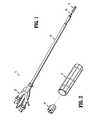
- FIG. 1is an exploded perspective view of a spray assembly according to the present disclosure
- FIG. 2is an enlarged perspective view of the insert and applicator tip of the spray assembly of FIG. 1 ;
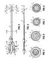
- FIG. 3is a top view of the spray assembly of FIG. 1 ;
- FIG. 4is a side view of the spray assembly of FIGS. 1 and 3 ;
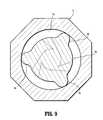
- FIG. 5is a cross-sectional end view taken along line 5 - 5 of FIG. 3 ;
- FIG. 6is a cross-sectional end view taken along line 6 - 6 of FIG. 3 ;
- FIG. 7is a cross-sectional end view taken along line 7 - 7 of FIG. 3 ;
- FIG. 8is a cross-sectional end view taken along line 8 - 8 of FIG. 3 ;
- FIG. 9is a cross-sectional end view taken along line 9 - 9 of FIG. 3 ;
- FIG. 10is a cross-sectional side view of the distal end of the spray assembly of FIGS. 1 and 3 ;
- FIG. 11is a distal end view of the spray assembly of FIGS. 1 and 3 ;
- FIG. 12is an enlarged cross-sectional side view of the distal end of the applicator tip of FIG. 11 ;
- FIGS. 13A-Dare side view ( FIG. 13A ), distal end view ( FIG. 13B ), proximal end view ( FIG. 13C ), and cross-sectional top view taken along line 13 D- 13 D of FIG. 13A ( FIG. 13D ) of the insert of FIG. 2 ;
- FIG. 14is an alternate embodiment of a spray assembly according to the present disclosure.
- FIG. 15is an enlarged cross-sectional side view of the distal end of an alternate embodiment of an applicator tip according to the present disclosure.
- FIG. 16is an enlarged cross-sectional end view of the applicator tip of FIG. 14 taken along line 16 - 16 OF FIG. 15 .
- Spray assembly 10includes a Y-connector 20 , an elongated body portion 30 extending distally from Y-connector 20 , and an applicator tip 70 mounted on a distal end of elongated body portion 30 .
- Spray assembly 10further includes an insert member 80 received between a distal end of elongated body portion 30 and a distal end of applicator tip 70 .
- Y-connector 20defines a substantially Y-shaped member 21 including first and second proximal extensions 22 , 24 , an air supply port 26 , and a collar 28 .
- first and second proximal extensions 22 , 24 and air supply port 26may be arranged in any manner.
- Each of first and second proximal extensions 22 , 24includes a tab 22 a , 24 a , respectively, for operable engagement with a bayonet coupling (not shown) found on standard syringes. It is envisioned, however, that first and second extensions 22 , 24 may configured for coupling with any source of fluid in any manner.
- First and second proximal extensions 22 , 24may further include component check valves 22 b , 24 b or other means for selectively regulating the flow from first and second proximal extensions 22 , 24 and prevent backflow.
- First and second component channels 23 , 25extend between first and second proximal extensions 22 , 24 and collar 28 .
- An air channel 27extends between air supply port 26 and collar 28 .
- First and second component channels 23 , 25 and/or air channel 27may be configured to include anti-backflow mechanisms.
- collar 28maintains first and second component channels 23 , 25 and air supply port 26 in fluid communication with a first and second component lumen 43 , 45 and an air lumen 47 ( FIG. 6 ), respectively, formed in inner multi-lumen shaft 40 of elongated body portion 30 .
- elongated body portion 30 of spray assembly 10includes an inner multi-lumen shaft 40 , an outer sleeve 50 ( FIG. 6 ) surrounding inner shaft 40 and a transition member 60 extending distally from outer sleeve 50 about inner shaft 40 .
- outer sleeve 50is rigid while inner multi-lumen shaft 40 and transition member 60 are flexible.
- Inner shaft 40 and outer sleeve 50are securely affixed to Y-connector 20 and include a vent lumen 46 ( FIG. 6 ) therebetween.
- Outer sleeve 50includes a proximal vent or opening 52 a ( FIG. 3 ) and a plurality of distal vents or openings 52 b ( FIG. 4 ).
- Proximal and distal vents 52 a , 52 bmay be of any number, size, configuration and arrangement.
- Distal vents 52 bare in fluid communication with proximal vent 52 a via vent lumen 46 .
- proximal end 40 a of inner shaft 40engages Y-connector 20 such that first and second component lumen 43 , 45 and air lumen 47 align with first and second component channels 23 , 25 and air lumen 27 ( FIG. 5 ), respectively.
- collar 28 of Y-connector 20is molded directly around the proximal end of elongated body portion 30 .
- elongated body portion 30may be selectively engagable with collar 28 such that elongated body portion 30 and collar 28 may be separated and one of the two replaced.
- elongated body portion 30may be securely affixed to collar 28 using adhesive, sonic welding or other suitable method.
- Inner shaft 40may further includes a wire or other formable material 48 configured to maintain elongated body portion 30 distal of outer sleeve 50 in a desired straight, bent or flexed condition. A proximal end of transition member 60 is received within vent lumen 46 between outer sleeve 50 and inner shaft 40 .
- Transition member 60extends from outer sleeve 50 about inner shaft 40 and may be of any length. Transition member 60 may include a flexible material, thereby permitting inner shaft 40 to be bent and formed. In an alternate embodiment, transition member 60 may be integrally formed with inner shaft 40 . In this manner, the portion of inner shaft extending beyond the distal end of outer sleeve 50 would have a larger diameter than the portion of inner shaft 40 within outer sleeve 50 .
- a distal end 60 b of transition member 60may include a groove, threading or other configuration to selectively receive a applicator tip 70 .
- applicator tip 70is a tubular member having an open proximal end 70 a and a substantially closed distal end 70 b .
- Applicator tip 70defines an engagement portion 72 , a mixing chamber 74 and an outlet 76 .
- Engagement portion 72is configured to selectively engage distal end 60 b of transition member 60 .
- Engagement portion 72may include grooves, tabs or other configurations corresponding to tabs, grooves and other configurations formed on the distal end of transition member 60 .
- Engagement portion 72may otherwise be configured to more securely engage the distal end of transition member 60 .
- Mixing chamber 74is an annular cavity in fluid communication with first and second component lumen 43 , 45 and air lumen 47 ( FIG. 5 ) of inner shaft 40 .
- Mixing chamber 74includes a proximal end 74 a and outlet 76 on a distal end 74 b .
- Mixing chamber 74is sized to receive insert 80 immediately adjacent to or flush against distal end 74 b .
- Outlet 76is formed in distal end 70 b of applicator tip 70 . Outlet 76 is configured to atomize the combined first and second components.
- outlet 76described distally from mixing chamber 74 , includes a first annular portion 76 a , a first tapered portion 76 b , a second annular portion 76 c , a second tapered portion 76 d and a recessed portion 76 e .
- Alternative configurations for atomizing a solutionare known and have been envisioned for use with spray assembly 10 .
- insert 80is defined by a substantially annular body 81 having proximal and distal ends 80 a , 80 b .
- Proximal and distal ends 80 a , 80 bare substantial mirror images of one another.
- Proximal and distal ends 80 a , 80 beach define substantially annular recesses 81 a , 81 b , respectively.
- each of proximal and distal ends 80 a , 80 bfurther includes a set of slots 82 a , 82 b .
- Slots 82 a , 82 bare included in both proximal and distal ends 80 a , 80 b in order to simplify the assembly process of spray assembly 10 . It is envisioned, however, that only one end of insert 80 may include slots 82 . Slots 82 a , 82 b are equally spaced about respective proximal and distal ends 80 a , 80 b . Although shown including three slots 82 a , 82 b , an insert 80 including two or more slots has been envisioned.
- Each of slots 82 a , 82 bdefines an opening angling outwardly between a line tangent to recesses 81 a , 81 b , respectively, and a degrees counter-clockwise from the tangent line.
- ais equal to twenty degrees (20°).
- Slots 82 a formed on proximal end 80 aare radial offset from slots 82 b formed on distal end 80 b .
- Insert 80includes three spacers 84 equally spaced about and extending longitudinally along annular body 81 . As will be discussed in further detail below, spacers 84 align and maintain insert 80 within mixing chamber 74 . It is envisioned that insert 80 may include more or less than three spacers 84 .
- applicator tip 70 of applicator assembly 10is shown in an assembled condition. Insert 80 is received immediately adjacent to, or flush against, the distal end of mixing chamber 74 of applicator tip 70 . Spacers 84 formed on annular body 81 maintain insert 80 radially centered within distal end 74 b of mixing chamber 74 . Distal end 60 b of transition member 60 is received within engagement portion 72 of applicator tip 70 . Mixing chamber 74 is sized such that distal end 60 b of transition member 60 and distal end 40 b of inner shaft 40 abut insert 80 .
- first and second sources of componentare connected with first and second proximal extensions 22 , 24 , respectively, formed in Y-connector 20 .
- the first and second componentsare ejected into first and second component channels 23 , 25 , respectively, and travel through first and second component lumen 43 , 45 , respectively formed in inner shaft 40 .
- Air or other gaseous fluidis provided to spray assembly 10 through air supply port 26 .
- the gas supplied through air supply port 26is a combination of oxygen (O 2 ) and carbon dioxide (CO 2 ); however, the use of other gases, alone or in combination, is envisioned.
- the airflows into air channel 27 and through air lumen 47 formed in inner shaft 47 .
- the first and second components and the air provided through Y-connector 20exit first and second lumen 43 , 45 and air lumen 47 , respectively, at distal end 40 b ( FIG. 3 ) of inner shaft 40 .
- the first and second components and the air exiting inner shaft 40encounter proximal end 80 a of insert 80 .
- the components and airinitially meet as the components and air are forced around insert 80 through the space created by spacers 84 between mixing chamber 74 and annular body 81 .
- the combinationis further mixed by the turbulent or swirling motion created by slots 82 b as the mixture enters recess 81 b .
- the swirling fluidis then ejected from applicator tip 70 through outlet 76 in the form of a cone spray.
- Insert 80is forced against and maintained flush with the distal end of mixing chamber 74 because of the contact between spacers 84 on annular body 81 and mixing chamber 74 . The force of the components and air against insert 80 also maintains insert 80 flush against the distal end of applicator tip 70 .
- mixing chamber 74is sized such that insert 80 is longitudinally spaced from distal end 30 b of elongated body member 30 , thereby foaming a cavity for the initial mixing of first and second components prior to encountering insert 80 .
- applicator tip 70includes a lip or ridge 72 a , to prevent engagement of elongated body portion 30 with insert 80 .
- the first and second components and gasare first combined within proximal end 74 a of mixing chamber 74 as the first and second components exit distal end 40 b of inner shaft 40 .
- the combined first and second componentsform a mixture that next encounters proximal end 80 a of insert 80 .
- the mixtureis forced around insert 80 through the space created by spacers 84 between mixing chamber 74 and annular body 81 .
- the mixtureis further mixed and swirled by slots 82 b as the mixture enters recess 81 b .
- the swirling fluidis then ejected from applicator tip 70 through outlet 76 in the form of a cone spray.
- distal end 80 b of insert 80is not flush against distal end 74 b of chamber 74 , the mixture would not swirl through slots 82 b thereby resulting in a jet-like spray.
- Insert 80is maintained flush against distal end of mixing chamber 74 by the force of the first and second component and gas flowing against proximal end 80 a thereof. Insert 80 is also forced against and maintained flush with distal end of mixing chamber 74 because of contact between spacers 84 on annular body 81 and mixing chamber 74 .
- distal end 74 b of mixing chamber 74 of applicator tip 70may alternately be configured to include radially extending slots 82 c formed about opening 76 .
- Slots 82 care similar in form and function to slots 82 a , 82 b formed in proximal and distal ends 80 a , 80 b , respectively of insert 80 .
- slots 82 cmay be of any number size, configuration or orientation.
- insert 80 areplaces insert 80 .
- Insert 80 ais configured to be retained within mixing chamber 74 in a manner similar to insert 80 , however, insert 80 a does not include slots 82 a , 82 b .
- Applicator tip 70may alternatively be configured to direct the first and second components into slots 82 c without insert 80 a.
- the spray assembly of the present disclosuremay be configured to mix and dispense a mixture including more than two components. It is further envisioned that the spray assembly may be configured for connection with more than one gas supply source.
Landscapes
- Health & Medical Sciences (AREA)
- Life Sciences & Earth Sciences (AREA)
- Animal Behavior & Ethology (AREA)
- Veterinary Medicine (AREA)
- Public Health (AREA)
- Engineering & Computer Science (AREA)
- Biomedical Technology (AREA)
- Heart & Thoracic Surgery (AREA)
- General Health & Medical Sciences (AREA)
- Anesthesiology (AREA)
- Hematology (AREA)
- Pulmonology (AREA)
- Biophysics (AREA)
- Surgery (AREA)
- Chemical & Material Sciences (AREA)
- Molecular Biology (AREA)
- Medical Informatics (AREA)
- Nuclear Medicine, Radiotherapy & Molecular Imaging (AREA)
- Dispersion Chemistry (AREA)
- Chemical Kinetics & Catalysis (AREA)
- Nozzles (AREA)
- Surgical Instruments (AREA)
- Media Introduction/Drainage Providing Device (AREA)
Abstract
Description
This application is a continuation of U.S. application Ser. No. 12/555,435 filed on Sep. 8, 2009, now U.S. Pat. No. 8,210,453 which claims the benefit of and priority to U.S. Provisional Patent Application No. 61/096,345, filed Sep. 12, 2008, the entire disclosure of which is incorporated by reference herein.
1. Technical Field
The present disclosure relates to spray applicators and methods of mixing two or more components. More particularly, the present disclosure relates to a spray assembly for mixing and applying a bioadhesive.
2. Background of Related Art
Polymers and other synthetic materials are currently being developed for use in internal and external wound closure. “Bioadhesives” are known in the art, as are various methods for applying the bioadhesive. Bioadhesives offer many significant advantages over conventional wound closure methods, i.e., using sutures, staples, clips or other suitable mechanical fasteners. Bioadhesives are faster and simpler to apply and have a tendency to promote quicker wound healing with less scarring.
Most bioadhesives are composed of components that have a tendency to immediately activate and in some instances, rapidly polymerize when combined with one another. Because of this immediate activation and/or rapid polymerization of the bioadhesive, the components comprising the bioadhesive may not be combined until immediately prior to application.
The increased use of endoscopic surgery for even some of the most complex procedures has presented a need for an applicator configured to apply a bioadhesive through an endoscopic port.
Provided is a spray assembly for dispensing a mixture. The spray assembly includes a connector configured for operable engagement with a first and a second source of component and a source of pressurized fluid, a tip operably connected to the connector, the tip including an opening and defining a mixing chamber between the distal end of the elongated member and the opening of the tip, and an insert member configured to be received in the mixing chamber, the insert member including a plurality of radially extending slots on at least one end of the insert, the plurality of radially extending slots being configured to mix the first and second components prior to the combination exiting the opening in the tip. The spray assembly may further include an elongated member extending between the connector and the tip, the elongated member having at least a first lumen configured for fluid communication with the first source of component, a second lumen configured for fluid communication with the second source of component, and a third lumen configured for fluid communication with the source of pressurized fluid. The spray assembly may further include a first and a second source of component. The insert member of the spray assembly may include three slots.
An alternate embodiment of a spray assembly for dispensing a mixture is also provided. The spray assembly includes a connector configured for operable engagement with a first and a second source of component and a source of pressurized fluid, and a tip operably connected to the connector, the tip including an opening and defining a mixing chamber between the distal end of the elongated member and the opening of the tip, the distal end of the mixing chamber including a plurality of radially extending slots formed about the opening, the plurality of radially extending slots being configured to mix the first and second components prior to the combination exiting the opening in the tip. The spray assembly may further include an elongated member extending between the connector and the tip, the elongated member having at least a first lumen configured for fluid communication with the first source of component, a second lumen configured for fluid communication with the second source of component, and a third lumen configured for fluid communication with the source of pressurized fluid,
The accompanying drawings, which are incorporated in and constitute a part of this specification, illustrate embodiments of the disclosure and, together with a general description of the disclosure given above, and the detailed description of the embodiment(s) given below, serve to explain the principles of the disclosure, wherein:
As shown below inFIGS. 1 and 2 , an embodiment of a spray assembly, i.e., a laparoscopic spray assembly, in accordance with the present disclosure is shown generally asspray assembly 10.Spray assembly 10 includes a Y-connector 20, anelongated body portion 30 extending distally from Y-connector 20, and anapplicator tip 70 mounted on a distal end ofelongated body portion 30.Spray assembly 10 further includes aninsert member 80 received between a distal end ofelongated body portion 30 and a distal end ofapplicator tip 70.
Referring now toFIGS. 3 and 4 , Y-connector 20 defines a substantially Y-shaped member 21 including first and secondproximal extensions air supply port 26, and acollar 28. Although shown in a substantially planar arrangement, first and secondproximal extensions air supply port 26 may be arranged in any manner. Each of first and secondproximal extensions tab second extensions proximal extensions component check valves proximal extensions second component channels proximal extensions collar 28. Anair channel 27 extends betweenair supply port 26 andcollar 28. First andsecond component channels air channel 27 may be configured to include anti-backflow mechanisms. As will be discussed in further detail below,collar 28 maintains first andsecond component channels air supply port 26 in fluid communication with a first andsecond component lumen FIG. 6 ), respectively, formed in innermulti-lumen shaft 40 ofelongated body portion 30.
With reference toFIGS. 5-9 ,elongated body portion 30 ofspray assembly 10 includes an innermulti-lumen shaft 40, an outer sleeve50 (FIG. 6 ) surroundinginner shaft 40 and atransition member 60 extending distally fromouter sleeve 50 aboutinner shaft 40. In one embodiment,outer sleeve 50 is rigid while innermulti-lumen shaft 40 andtransition member 60 are flexible.Inner shaft 40 andouter sleeve 50 are securely affixed to Y-connector 20 and include a vent lumen46 (FIG. 6 ) therebetween.Outer sleeve 50 includes a proximal vent or opening52a(FIG. 3 ) and a plurality of distal vents oropenings 52b(FIG. 4 ). Proximal anddistal vents Distal vents 52bare in fluid communication withproximal vent 52aviavent lumen 46.
As discussed above,proximal end 40aofinner shaft 40 engages Y-connector 20 such that first andsecond component lumen air lumen 47 align with first andsecond component channels FIG. 5 ), respectively. In one embodiment,collar 28 of Y-connector 20 is molded directly around the proximal end ofelongated body portion 30. Alternatively,elongated body portion 30 may be selectively engagable withcollar 28 such thatelongated body portion 30 andcollar 28 may be separated and one of the two replaced. In yet another embodiment,elongated body portion 30 may be securely affixed tocollar 28 using adhesive, sonic welding or other suitable method.Inner shaft 40 may further includes a wire or otherformable material 48 configured to maintainelongated body portion 30 distal ofouter sleeve 50 in a desired straight, bent or flexed condition. A proximal end oftransition member 60 is received withinvent lumen 46 betweenouter sleeve 50 andinner shaft 40.
Turning now toFIGS. 8-12 ,applicator tip 70 is a tubular member having an openproximal end 70aand a substantially closeddistal end 70b.Applicator tip 70 defines anengagement portion 72, a mixingchamber 74 and anoutlet 76.Engagement portion 72 is configured to selectively engagedistal end 60boftransition member 60.Engagement portion 72 may include grooves, tabs or other configurations corresponding to tabs, grooves and other configurations formed on the distal end oftransition member 60.Engagement portion 72 may otherwise be configured to more securely engage the distal end oftransition member 60.
Mixingchamber 74 is an annular cavity in fluid communication with first andsecond component lumen FIG. 5 ) ofinner shaft 40. Mixingchamber 74 includes aproximal end 74aandoutlet 76 on adistal end 74b. Mixingchamber 74 is sized to receiveinsert 80 immediately adjacent to or flush againstdistal end 74b.Outlet 76 is formed indistal end 70bofapplicator tip 70.Outlet 76 is configured to atomize the combined first and second components. With reference toFIG. 12 , in one embodiment,outlet 76, described distally from mixingchamber 74, includes a firstannular portion 76a, a first taperedportion 76b, a secondannular portion 76c, a second taperedportion 76dand a recessedportion 76e. Alternative configurations for atomizing a solution are known and have been envisioned for use withspray assembly 10.
Turning now toFIGS. 13A-13D , insert80 is defined by a substantiallyannular body 81 having proximal and distal ends80a,80b. Proximal and distal ends80a,80bare substantial mirror images of one another. Proximal and distal ends80a,80beach define substantiallyannular recesses slots Slots spray assembly 10. It is envisioned, however, that only one end ofinsert 80 may include slots82.Slots slots insert 80 including two or more slots has been envisioned. Each ofslots recesses Slots 82aformed onproximal end 80aare radial offset fromslots 82bformed ondistal end 80b.Insert 80 includes threespacers 84 equally spaced about and extending longitudinally alongannular body 81. As will be discussed in further detail below,spacers 84 align and maintaininsert 80 within mixingchamber 74. It is envisioned thatinsert 80 may include more or less than threespacers 84.
With reference back toFIG. 10 ,applicator tip 70 ofapplicator assembly 10 is shown in an assembled condition.Insert 80 is received immediately adjacent to, or flush against, the distal end of mixingchamber 74 ofapplicator tip 70.Spacers 84 formed onannular body 81 maintaininsert 80 radially centered withindistal end 74bof mixingchamber 74.Distal end 60boftransition member 60 is received withinengagement portion 72 ofapplicator tip 70. Mixingchamber 74 is sized such thatdistal end 60boftransition member 60 anddistal end 40bofinner shaft 40abut insert 80.
In operation, first and second sources of component (not shown) are connected with first and secondproximal extensions connector 20. The first and second components are ejected into first andsecond component channels second component lumen inner shaft 40. Air or other gaseous fluid is provided to sprayassembly 10 throughair supply port 26. In one embodiment, the gas supplied throughair supply port 26 is a combination of oxygen (O2) and carbon dioxide (CO2); however, the use of other gases, alone or in combination, is envisioned. The air flows intoair channel 27 and throughair lumen 47 formed ininner shaft 47. The first and second components and the air provided through Y-connector 20 exit first andsecond lumen air lumen 47, respectively, atdistal end 40b(FIG. 3 ) ofinner shaft 40.
The first and second components and the air exitinginner shaft 40 encounterproximal end 80aofinsert 80. The components and air initially meet as the components and air are forced aroundinsert 80 through the space created byspacers 84 between mixingchamber 74 andannular body 81. When the component/gas combination reachesdistal end 80bofinsert 80, the combination is further mixed by the turbulent or swirling motion created byslots 82bas the mixture entersrecess 81b. The swirling fluid is then ejected fromapplicator tip 70 throughoutlet 76 in the form of a cone spray. In the event thatdistal end 80bofinsert 80 is not flush against the distal end ofchamber 74, the mixture would not swirl throughslots 82bthereby resulting in a jet-like spray throughoutlet 76.Insert 80 is forced against and maintained flush with the distal end of mixingchamber 74 because of the contact betweenspacers 84 onannular body 81 and mixingchamber 74. The force of the components and air againstinsert 80 also maintainsinsert 80 flush against the distal end ofapplicator tip 70.
With reference toFIG. 14 , in an alternate embodiment ofapplicator tip 70, mixingchamber 74 is sized such thatinsert 80 is longitudinally spaced fromdistal end 30bofelongated body member 30, thereby foaming a cavity for the initial mixing of first and second components prior to encounteringinsert 80. In one embodiment,applicator tip 70 includes a lip orridge 72a, to prevent engagement ofelongated body portion 30 withinsert 80. The first and second components and gas are first combined withinproximal end 74aof mixingchamber 74 as the first and second components exitdistal end 40bofinner shaft 40. The combined first and second components form a mixture that next encountersproximal end 80aofinsert 80. The mixture is forced aroundinsert 80 through the space created byspacers 84 between mixingchamber 74 andannular body 81. When the mixture reachesdistal end 80bofinsert 80, the mixture is further mixed and swirled byslots 82bas the mixture entersrecess 81b. The swirling fluid is then ejected fromapplicator tip 70 throughoutlet 76 in the form of a cone spray. As discussed above, in the event thatdistal end 80bofinsert 80 is not flush againstdistal end 74bofchamber 74, the mixture would not swirl throughslots 82bthereby resulting in a jet-like spray.Insert 80 is maintained flush against distal end of mixingchamber 74 by the force of the first and second component and gas flowing againstproximal end 80athereof.Insert 80 is also forced against and maintained flush with distal end of mixingchamber 74 because of contact betweenspacers 84 onannular body 81 and mixingchamber 74.
Turning now toFIGS. 15 and 16 ,distal end 74bof mixingchamber 74 ofapplicator tip 70 may alternately be configured to include radially extendingslots 82cformed about opening76.Slots 82care similar in form and function toslots insert 80. As withslots slots 82cmay be of any number size, configuration or orientation. In a spray assembly utilizing mixingchamber 74 havingslots 82c, insert80areplacesinsert 80.Insert 80ais configured to be retained within mixingchamber 74 in a manner similar to insert80, however, insert80adoes not includeslots Applicator tip 70, may alternatively be configured to direct the first and second components intoslots 82cwithoutinsert 80a.
Although the illustrative embodiments of the present disclosure have been described herein with reference to the accompanying drawings, it is to be understood that the disclosure is not limited to those precise embodiments, and that various other changes and modifications may be effected therein by one skilled in the art without departing from the scope or spirit of the disclosure. For example, it is envisioned that the spray assembly of the present disclosure may be configured to mix and dispense a mixture including more than two components. It is further envisioned that the spray assembly may be configured for connection with more than one gas supply source.
Claims (14)
1. A spray assembly for dispensing a mixture, the assembly comprising:
a connector configured for operable engagement with a first source of component and a second source of component;
an elongated member operably connected to and extending distally from the connector, the elongated member including an inner shaft and an outer sleeve, and defining a vent lumen between the inner shaft and outer sleeve, the inner shaft defines at least a first lumen configured for fluid communication with the first source of component and a second lumen configured for fluid communication with the second source of component;
a tip operably connected to the connector, the tip including an opening and defining a mixing chamber between a distal end of the elongated member and the opening of the tip; and
an insert member configured to be received in the mixing chamber, the insert member defining at least one radially extending slot on a first end of the insert member and at least one radially extending slot on a second end of the insert member, each of the radially extending slots being configured to mix the first and second components prior to the combination exiting the opening in the tip.
2. The spray assembly ofclaim 1 , further including a first and a second source of component.
3. The spray assembly ofclaim 1 , wherein the insert member includes three slots formed on the first end.
4. The spray assembly ofclaim 1 , wherein the at least one radially extending slot on the first end of the insert includes a plurality of slots.
5. The spray assembly ofclaim 1 , wherein the at least one radially extending slot on the second end of the insert includes a plurality of slots.
6. The spray assembly ofclaim 1 , wherein the outer sleeve includes at least one lateral opening in a proximal end thereof and at least one lateral opening in a distal end thereof.
7. The spray assembly ofclaim 1 , wherein the elongated member includes a formable member extending substantially the length thereof to permit forming of the inner shaft.
8. The spray assembly ofclaim 1 , further including a transition member operably connecting the elongated member and the tip.
9. The spray assembly ofclaim 1 , wherein the insert member includes a plurality of spacers extending longitudinally along substantially the length thereof.
10. The spray assembly ofclaim 1 , wherein the insert member further defines an annular recess on each of the first and second ends of the insert member.
11. The spray assembly ofclaim 10 , wherein the at least one radially extending slot in each of the first and second ends is formed between a line tangent to the respective annular recess and a line a degrees counter-clockwise from the tangent line.
12. The spray assembly ofclaim 11 , wherein α is about twenty degrees.
13. The spray assembly ofclaim 1 , wherein a distal end of the elongated body abuts the first end of the insert.
14. The spray assembly ofclaim 1 , wherein the outer sleeve includes a plurality of lateral openings formed in the distal end.
Priority Applications (6)
| Application Number | Priority Date | Filing Date | Title |
|---|---|---|---|
| US13/493,207US8616468B2 (en) | 2008-09-12 | 2012-06-11 | Spray applicator |
| US14/143,605US9101946B2 (en) | 2008-09-12 | 2013-12-30 | Spray applicator |
| US14/809,693US9517478B2 (en) | 2008-09-12 | 2015-07-27 | Spray applicator |
| US15/374,250US9700290B2 (en) | 2008-09-12 | 2016-12-09 | Spray applicator |
| US15/622,489US10092280B2 (en) | 2008-09-12 | 2017-06-14 | Spray applicator |
| US16/151,546US20190029660A1 (en) | 2008-09-12 | 2018-10-04 | Spray applicator |
Applications Claiming Priority (3)
| Application Number | Priority Date | Filing Date | Title |
|---|---|---|---|
| US9634508P | 2008-09-12 | 2008-09-12 | |
| US12/555,435US8210453B2 (en) | 2008-09-12 | 2009-09-08 | Spray applicator |
| US13/493,207US8616468B2 (en) | 2008-09-12 | 2012-06-11 | Spray applicator |
Related Parent Applications (1)
| Application Number | Title | Priority Date | Filing Date |
|---|---|---|---|
| US12/555,435ContinuationUS8210453B2 (en) | 2008-09-12 | 2009-09-08 | Spray applicator |
Related Child Applications (1)
| Application Number | Title | Priority Date | Filing Date |
|---|---|---|---|
| US14/143,605ContinuationUS9101946B2 (en) | 2008-09-12 | 2013-12-30 | Spray applicator |
Publications (2)
| Publication Number | Publication Date |
|---|---|
| US20120248220A1 US20120248220A1 (en) | 2012-10-04 |
| US8616468B2true US8616468B2 (en) | 2013-12-31 |
Family
ID=41401553
Family Applications (7)
| Application Number | Title | Priority Date | Filing Date |
|---|---|---|---|
| US12/555,435Active2029-11-05US8210453B2 (en) | 2008-09-12 | 2009-09-08 | Spray applicator |
| US13/493,207ActiveUS8616468B2 (en) | 2008-09-12 | 2012-06-11 | Spray applicator |
| US14/143,605ActiveUS9101946B2 (en) | 2008-09-12 | 2013-12-30 | Spray applicator |
| US14/809,693ActiveUS9517478B2 (en) | 2008-09-12 | 2015-07-27 | Spray applicator |
| US15/374,250Expired - Fee RelatedUS9700290B2 (en) | 2008-09-12 | 2016-12-09 | Spray applicator |
| US15/622,489ActiveUS10092280B2 (en) | 2008-09-12 | 2017-06-14 | Spray applicator |
| US16/151,546AbandonedUS20190029660A1 (en) | 2008-09-12 | 2018-10-04 | Spray applicator |
Family Applications Before (1)
| Application Number | Title | Priority Date | Filing Date |
|---|---|---|---|
| US12/555,435Active2029-11-05US8210453B2 (en) | 2008-09-12 | 2009-09-08 | Spray applicator |
Family Applications After (5)
| Application Number | Title | Priority Date | Filing Date |
|---|---|---|---|
| US14/143,605ActiveUS9101946B2 (en) | 2008-09-12 | 2013-12-30 | Spray applicator |
| US14/809,693ActiveUS9517478B2 (en) | 2008-09-12 | 2015-07-27 | Spray applicator |
| US15/374,250Expired - Fee RelatedUS9700290B2 (en) | 2008-09-12 | 2016-12-09 | Spray applicator |
| US15/622,489ActiveUS10092280B2 (en) | 2008-09-12 | 2017-06-14 | Spray applicator |
| US16/151,546AbandonedUS20190029660A1 (en) | 2008-09-12 | 2018-10-04 | Spray applicator |
Country Status (6)
| Country | Link |
|---|---|
| US (7) | US8210453B2 (en) |
| EP (1) | EP2163204B1 (en) |
| JP (1) | JP5498747B2 (en) |
| AU (1) | AU2009213079B2 (en) |
| CA (1) | CA2678428C (en) |
| ES (1) | ES2569346T3 (en) |
Cited By (4)
| Publication number | Priority date | Publication date | Assignee | Title |
|---|---|---|---|---|
| US9572555B1 (en)* | 2015-09-24 | 2017-02-21 | Ethicon, Inc. | Spray or drip tips having multiple outlet channels |
| US10952709B2 (en) | 2014-04-04 | 2021-03-23 | Hyperbranch Medical Technology, Inc. | Extended tip spray applicator for two-component surgical sealant, and methods of use thereof |
| US11697128B2 (en) | 2020-08-21 | 2023-07-11 | Baxter International Inc. | Handheld gas spray system for mixing and dispensing multi-component compositions |
| US12343454B2 (en) | 2020-11-12 | 2025-07-01 | Pramand LLC | Hydrogels formed in situ and composition design for intrauterine use |
Families Citing this family (105)
| Publication number | Priority date | Publication date | Assignee | Title |
|---|---|---|---|---|
| AU2002348033B2 (en) | 2001-10-23 | 2008-05-29 | Covidien Lp | Surgical fasteners |
| US7938307B2 (en) | 2004-10-18 | 2011-05-10 | Tyco Healthcare Group Lp | Support structures and methods of using the same |
| US7845536B2 (en) | 2004-10-18 | 2010-12-07 | Tyco Healthcare Group Lp | Annular adhesive structure |
| US9364229B2 (en) | 2005-03-15 | 2016-06-14 | Covidien Lp | Circular anastomosis structures |
| US7845533B2 (en) | 2007-06-22 | 2010-12-07 | Tyco Healthcare Group Lp | Detachable buttress material retention systems for use with a surgical stapling device |
| EP3087929B1 (en) | 2007-03-06 | 2020-04-29 | Covidien LP | Surgical stapling apparatus |
| US7665646B2 (en) | 2007-06-18 | 2010-02-23 | Tyco Healthcare Group Lp | Interlocking buttress material retention system |
| US8210453B2 (en) | 2008-09-12 | 2012-07-03 | Confluent Surgical, Inc. | Spray applicator |
| US9681860B2 (en)* | 2008-10-24 | 2017-06-20 | Dennis L Steffen | Halo tip spray head atomizer delivery manifold device |
| US20100147921A1 (en) | 2008-12-16 | 2010-06-17 | Lee Olson | Surgical Apparatus Including Surgical Buttress |
| US9486215B2 (en) | 2009-03-31 | 2016-11-08 | Covidien Lp | Surgical stapling apparatus |
| US10293553B2 (en) | 2009-10-15 | 2019-05-21 | Covidien Lp | Buttress brachytherapy and integrated staple line markers for margin identification |
| US20150231409A1 (en) | 2009-10-15 | 2015-08-20 | Covidien Lp | Buttress brachytherapy and integrated staple line markers for margin identification |
| US8672237B2 (en) | 2010-06-25 | 2014-03-18 | Baxter International Inc. | Device for mixing and dispensing of two-component reactive surgical sealant |
| US9125633B2 (en)* | 2010-06-25 | 2015-09-08 | Baxter International Inc. | Device for mixing and dispensing of two-component reactive surgical sealant |
| US8479968B2 (en) | 2011-03-10 | 2013-07-09 | Covidien Lp | Surgical instrument buttress attachment |
| EP2726512B1 (en) | 2011-06-29 | 2017-10-11 | Covidien LP | Dissolution of oxidized cellulose |
| US8584920B2 (en) | 2011-11-04 | 2013-11-19 | Covidien Lp | Surgical stapling apparatus including releasable buttress |
| US9351731B2 (en) | 2011-12-14 | 2016-05-31 | Covidien Lp | Surgical stapling apparatus including releasable surgical buttress |
| US9113885B2 (en) | 2011-12-14 | 2015-08-25 | Covidien Lp | Buttress assembly for use with surgical stapling device |
| US8967448B2 (en) | 2011-12-14 | 2015-03-03 | Covidien Lp | Surgical stapling apparatus including buttress attachment via tabs |
| US9237892B2 (en) | 2011-12-14 | 2016-01-19 | Covidien Lp | Buttress attachment to the cartridge surface |
| US9326773B2 (en) | 2012-01-26 | 2016-05-03 | Covidien Lp | Surgical device including buttress material |
| US9010609B2 (en) | 2012-01-26 | 2015-04-21 | Covidien Lp | Circular stapler including buttress |
| US9010612B2 (en) | 2012-01-26 | 2015-04-21 | Covidien Lp | Buttress support design for EEA anvil |
| US8820606B2 (en) | 2012-02-24 | 2014-09-02 | Covidien Lp | Buttress retention system for linear endostaplers |
| WO2013137062A1 (en)* | 2012-03-15 | 2013-09-19 | テルモ株式会社 | Applicator |
| US20130323312A1 (en) | 2012-05-31 | 2013-12-05 | Confluent Surgical, Inc. | Microspheres Including Oxidized Cellulose |
| US9168227B2 (en) | 2012-05-31 | 2015-10-27 | Covidien Lp | Multi-encapsulated microspheres made with oxidized cellulose for in-situ reactions |
| US9271937B2 (en) | 2012-05-31 | 2016-03-01 | Covidien Lp | Oxidized cellulose microspheres |
| US9138489B2 (en) | 2012-05-31 | 2015-09-22 | Covidien Lp | Oxidized cellulose miczrospheres including visualization agents |
| US9447197B2 (en) | 2012-06-28 | 2016-09-20 | Covidien Lp | Dissolution of oxidized cellulose and particle preparation by dispersion and neutralization |
| US10040871B2 (en) | 2012-06-28 | 2018-08-07 | Covidien Lp | Medical devices based on oxidized cellulose |
| US9447196B2 (en) | 2012-06-28 | 2016-09-20 | Covidien Lp | Dissolution of oxidized cellulose and particle preparation by solvent and non-solvent precipitation |
| US9499636B2 (en) | 2012-06-28 | 2016-11-22 | Covidien Lp | Dissolution of oxidized cellulose and particle preparation by cross-linking with multivalent cations |
| US20140048580A1 (en) | 2012-08-20 | 2014-02-20 | Covidien Lp | Buttress attachment features for surgical stapling apparatus |
| CA2826786A1 (en) | 2012-09-17 | 2014-03-17 | Confluent Surgical, Inc. | Multi-encapsulated formulations made with oxidized cellulose |
| US9161753B2 (en) | 2012-10-10 | 2015-10-20 | Covidien Lp | Buttress fixation for a circular stapler |
| EP2722008B1 (en) | 2012-10-16 | 2018-01-17 | Erbe Elektromedizin GmbH | Nozzle for feeding of biological material, in particular cells, medical device having such a nozzle, use of a nozzle, method for mixing fluids and apparatus |
| US20140131418A1 (en) | 2012-11-09 | 2014-05-15 | Covidien Lp | Surgical Stapling Apparatus Including Buttress Attachment |
| US20140239047A1 (en) | 2013-02-28 | 2014-08-28 | Covidien Lp | Adherence concepts for non-woven absorbable felt buttresses |
| US9782173B2 (en) | 2013-03-07 | 2017-10-10 | Covidien Lp | Circular stapling device including buttress release mechanism |
| US10413566B2 (en) | 2013-03-15 | 2019-09-17 | Covidien Lp | Thixotropic oxidized cellulose solutions and medical applications thereof |
| US10144017B2 (en)* | 2013-03-15 | 2018-12-04 | Neomend, Inc. | Centrifugal mixing spray nozzle |
| US9782430B2 (en) | 2013-03-15 | 2017-10-10 | Covidien Lp | Resorbable oxidized cellulose embolization solution |
| US10328095B2 (en) | 2013-03-15 | 2019-06-25 | Covidien Lp | Resorbable oxidized cellulose embolization microspheres |
| DE102013214032B4 (en) | 2013-07-17 | 2025-05-08 | Aesculap Ag | Spray applicator for spraying a multi-component fluid |
| US9802166B2 (en)* | 2013-08-27 | 2017-10-31 | Gary Hammerlund | Vortex mixing system |
| US9844378B2 (en) | 2014-04-29 | 2017-12-19 | Covidien Lp | Surgical stapling apparatus and methods of adhering a surgical buttress thereto |
| US10420901B2 (en)* | 2014-09-04 | 2019-09-24 | Ethicon, Inc. | Minimally clogging device for delivery of fluids |
| US10449152B2 (en) | 2014-09-26 | 2019-10-22 | Covidien Lp | Drug loaded microspheres for post-operative chronic pain |
| US10835216B2 (en) | 2014-12-24 | 2020-11-17 | Covidien Lp | Spinneret for manufacture of melt blown nonwoven fabric |
| US10470767B2 (en) | 2015-02-10 | 2019-11-12 | Covidien Lp | Surgical stapling instrument having ultrasonic energy delivery |
| US11020578B2 (en) | 2015-04-10 | 2021-06-01 | Covidien Lp | Surgical stapler with integrated bladder |
| CA2925606A1 (en) | 2015-04-23 | 2016-10-23 | Covidien Lp | Resorbable oxidized cellulose embolization solution |
| US10639656B1 (en) | 2015-10-16 | 2020-05-05 | Gary M. Hammerlund | Crossover prevention valve |
| US11857994B1 (en) | 2015-10-16 | 2024-01-02 | Gary M. Hammerlund | Crossover prevention valve |
| JP6350951B2 (en)* | 2016-03-17 | 2018-07-04 | パナソニックIpマネジメント株式会社 | Spraying equipment |
| US10959731B2 (en) | 2016-06-14 | 2021-03-30 | Covidien Lp | Buttress attachment for surgical stapling instrument |
| AU2017204280A1 (en) | 2016-08-12 | 2018-03-01 | Covidien Lp | Thixotropic oxidized cellulose solutions and medical applications thereof |
| US11026686B2 (en) | 2016-11-08 | 2021-06-08 | Covidien Lp | Structure for attaching buttress to anvil and/or cartridge of surgical stapling instrument |
| US10737058B2 (en)* | 2016-12-28 | 2020-08-11 | Ethicon Llc | Rigid and flexible laparoscopic multiple component material dispensing devices and methods |
| US10874768B2 (en) | 2017-01-20 | 2020-12-29 | Covidien Lp | Drug eluting medical device |
| US10925607B2 (en) | 2017-02-28 | 2021-02-23 | Covidien Lp | Surgical stapling apparatus with staple sheath |
| US10368868B2 (en) | 2017-03-09 | 2019-08-06 | Covidien Lp | Structure for attaching buttress material to anvil and cartridge of surgical stapling instrument |
| US11096610B2 (en) | 2017-03-28 | 2021-08-24 | Covidien Lp | Surgical implants including sensing fibers |
| US10849625B2 (en) | 2017-08-07 | 2020-12-01 | Covidien Lp | Surgical buttress retention systems for surgical stapling apparatus |
| US10945733B2 (en) | 2017-08-23 | 2021-03-16 | Covidien Lp | Surgical buttress reload and tip attachment assemblies for surgical stapling apparatus |
| US11141151B2 (en) | 2017-12-08 | 2021-10-12 | Covidien Lp | Surgical buttress for circular stapling |
| US11065000B2 (en) | 2018-02-22 | 2021-07-20 | Covidien Lp | Surgical buttresses for surgical stapling apparatus |
| CA3095939C (en)* | 2018-04-06 | 2023-09-26 | Frank Levy | Apparatus and method for producing an enriched medical suspension |
| US10758237B2 (en) | 2018-04-30 | 2020-09-01 | Covidien Lp | Circular stapling apparatus with pinned buttress |
| US11284896B2 (en) | 2018-05-09 | 2022-03-29 | Covidien Lp | Surgical buttress loading and attaching/detaching assemblies |
| US11426163B2 (en) | 2018-05-09 | 2022-08-30 | Covidien Lp | Universal linear surgical stapling buttress |
| US11432818B2 (en) | 2018-05-09 | 2022-09-06 | Covidien Lp | Surgical buttress assemblies |
| US11219460B2 (en) | 2018-07-02 | 2022-01-11 | Covidien Lp | Surgical stapling apparatus with anvil buttress |
| US10806459B2 (en) | 2018-09-14 | 2020-10-20 | Covidien Lp | Drug patterned reinforcement material for circular anastomosis |
| US10952729B2 (en) | 2018-10-03 | 2021-03-23 | Covidien Lp | Universal linear buttress retention/release assemblies and methods |
| JP7617016B2 (en)* | 2019-03-22 | 2025-01-17 | シー・アール・バード・インコーポレーテッド | SEALANT DELIVERY DEVICE FOR USE IN PULMONARY PROCEDURES AND SYSTEMS AND METHODS FOR PREPARATION THEREOF - Patent application |
| US11730472B2 (en) | 2019-04-25 | 2023-08-22 | Covidien Lp | Surgical system and surgical loading units thereof |
| US11478245B2 (en) | 2019-05-08 | 2022-10-25 | Covidien Lp | Surgical stapling device |
| US11596403B2 (en) | 2019-05-08 | 2023-03-07 | Covidien Lp | Surgical stapling device |
| US11911787B1 (en) | 2019-08-16 | 2024-02-27 | Gary Hammerlund | Split manifold and method for multiple part fluid applications |
| US11969169B2 (en) | 2019-09-10 | 2024-04-30 | Covidien Lp | Anvil buttress loading unit for a surgical stapling apparatus |
| US11358165B2 (en) | 2019-10-04 | 2022-06-14 | Ethicon, Inc. | Spray devices having side-by-side spray tips for dispensing two fluids that chemically react together |
| US12207810B2 (en) | 2019-10-04 | 2025-01-28 | Ethicon, Inc. | Dispensing systems and devices having anti-clogging spray tips for dispensing two or more fluids that react together |
| US11571208B2 (en) | 2019-10-11 | 2023-02-07 | Covidien Lp | Surgical buttress loading units |
| WO2021101767A1 (en) | 2019-11-18 | 2021-05-27 | Boston Scientific Scimed, Inc. | Medical devices for endoscopically dispensing agents and related methods of use |
| US11523824B2 (en) | 2019-12-12 | 2022-12-13 | Covidien Lp | Anvil buttress loading for a surgical stapling apparatus |
| US11547407B2 (en) | 2020-03-19 | 2023-01-10 | Covidien Lp | Staple line reinforcement for surgical stapling apparatus |
| US11337699B2 (en) | 2020-04-28 | 2022-05-24 | Covidien Lp | Magnesium infused surgical buttress for surgical stapler |
| US11707276B2 (en) | 2020-09-08 | 2023-07-25 | Covidien Lp | Surgical buttress assemblies and techniques for surgical stapling |
| US11399833B2 (en) | 2020-10-19 | 2022-08-02 | Covidien Lp | Anvil buttress attachment for surgical stapling apparatus |
| US11534170B2 (en) | 2021-01-04 | 2022-12-27 | Covidien Lp | Anvil buttress attachment for surgical stapling apparatus |
| CN113231214B (en)* | 2021-04-23 | 2022-03-04 | 哈尔滨瀚邦医疗科技有限公司 | Endoscope with tube |
| US11510670B1 (en) | 2021-06-23 | 2022-11-29 | Covidien Lp | Buttress attachment for surgical stapling apparatus |
| US11596399B2 (en) | 2021-06-23 | 2023-03-07 | Covidien Lp | Anvil buttress attachment for surgical stapling apparatus |
| US11672538B2 (en) | 2021-06-24 | 2023-06-13 | Covidien Lp | Surgical stapling device including a buttress retention assembly |
| US11678879B2 (en) | 2021-07-01 | 2023-06-20 | Covidien Lp | Buttress attachment for surgical stapling apparatus |
| US11684368B2 (en) | 2021-07-14 | 2023-06-27 | Covidien Lp | Surgical stapling device including a buttress retention assembly |
| US12076013B2 (en) | 2021-08-03 | 2024-09-03 | Covidien Lp | Surgical buttress attachment assemblies for surgical stapling apparatus |
| US11801052B2 (en) | 2021-08-30 | 2023-10-31 | Covidien Lp | Assemblies for surgical stapling instruments |
| US11751875B2 (en) | 2021-10-13 | 2023-09-12 | Coviden Lp | Surgical buttress attachment assemblies for surgical stapling apparatus |
| US11806017B2 (en) | 2021-11-23 | 2023-11-07 | Covidien Lp | Anvil buttress loading system for surgical stapling apparatus |
| EP4482400A1 (en) | 2022-02-24 | 2025-01-01 | Covidien LP | Surgical medical devices |
Citations (95)
| Publication number | Priority date | Publication date | Assignee | Title |
|---|---|---|---|---|
| US3828980A (en) | 1972-11-06 | 1974-08-13 | Chem Dev Corp | Dispenser for precisely metered dispensing of viscous fluids |
| US4040420A (en) | 1976-04-22 | 1977-08-09 | General Dynamics | Packaging and dispensing kit |
| US4359049A (en) | 1980-04-02 | 1982-11-16 | Immuno Aktiengesellschaft Fur Chemisch-Medizinische Produkte | Apparatus for applying a tissue adhesive on the basis of human or animal proteins |
| US4538920A (en) | 1983-03-03 | 1985-09-03 | Minnesota Mining And Manufacturing Company | Static mixing device |
| US4631055A (en) | 1984-03-29 | 1986-12-23 | Immuno Aktiengesellschaft Fur Chemisch-Medizinische Produkte | Apparatus for applying a tissue adhesive |
| US4735616A (en) | 1985-06-20 | 1988-04-05 | Immuno Aktiengesellschaft Fur Chemisch-Medizinische Produkte | Arrangement for applying a tissue adhesive |
| US4753536A (en) | 1987-03-09 | 1988-06-28 | Spehar Edward R | Dispensing mixer for the storage and mixing of separate materials |
| US4767026A (en) | 1987-01-16 | 1988-08-30 | Keller Wilhelm A | Dispensing and mixing apparatus |
| US4842581A (en) | 1987-09-11 | 1989-06-27 | Davis Richard C | Medical lavage apparatus |
| US4874368A (en) | 1988-07-25 | 1989-10-17 | Micromedics, Inc. | Fibrin glue delivery system |
| US4978336A (en) | 1987-09-29 | 1990-12-18 | Hemaedics, Inc. | Biological syringe system |
| US4979942A (en) | 1989-10-16 | 1990-12-25 | Johnson & Johnson Medical, Inc. | Two component syringe delivery system |
| JPH0332959A (en) | 1989-06-30 | 1991-02-13 | Suzuki Motor Corp | Control device for passive seat belt |
| US5049135A (en) | 1990-09-18 | 1991-09-17 | Code Blue Medical Corporation | Medical lavage apparatus |
| US5104375A (en) | 1989-10-16 | 1992-04-14 | Johnson & Johnson Medical, Inc. | Locking holder for a pair of syringes and method of use |
| US5116315A (en) | 1989-10-03 | 1992-05-26 | Hemaedics, Inc. | Biological syringe system |
| US5249709A (en) | 1989-10-16 | 1993-10-05 | Plas-Pak Industries, Inc. | Cartridge system for dispensing predetermined ratios of semi-liquid materials |
| US5249862A (en) | 1990-12-21 | 1993-10-05 | Thera Patent Gmbh & Co.Kg Gesellschaft Fur Industrielle Schutzrechte | Dynamic mixer |
| US5328462A (en) | 1993-09-03 | 1994-07-12 | Ultradent Products, Inc. | Methods and apparatus for mixing and dispensing multi-part compositions |
| US5333760A (en) | 1992-12-28 | 1994-08-02 | Coltene/Whaledent, Inc. | Dispensing and mixing apparatus |
| US5413253A (en) | 1993-12-06 | 1995-05-09 | Coltene/Whaledent, Inc. | Static mixer |
| US5445614A (en) | 1993-10-20 | 1995-08-29 | Habley Medical Technology Corporation | Pharmaceutical storage and mixing syringe |
| US5474540A (en) | 1994-03-25 | 1995-12-12 | Micromedics, Inc. | Fluid separation control attachment for physiologic glue applicator |
| EP0689874A1 (en) | 1994-06-28 | 1996-01-03 | BEHRINGWERKE Aktiengesellschaft | Apparatus for spraying a mixture of two components |
| DE29516077U1 (en) | 1995-10-10 | 1997-02-06 | Maslanka, Harald, 78532 Tuttlingen | Spraying device |
| US5643206A (en) | 1993-09-03 | 1997-07-01 | Ultradent Products, Inc. | Methods and apparatus for mixing and dispensing multi-part compositions |
| US5740965A (en) | 1995-04-18 | 1998-04-21 | Machida Endoscope Co., Ltd. | Adhesive sprayer for living body |
| US5810885A (en) | 1994-12-28 | 1998-09-22 | Omrix Biopharm Sa | Device for applying one or several fluids |
| US5819988A (en) | 1997-04-01 | 1998-10-13 | Sawhney; Ravi K. | Double-barreled syringe with detachable locking mixing tip |
| USRE36235E (en) | 1987-01-16 | 1999-06-29 | Wilhelm Keller | Dispensing and mixing apparatus |
| US6047861A (en) | 1998-04-15 | 2000-04-11 | Vir Engineering, Inc. | Two component fluid dispenser |
| US6065645A (en) | 1997-04-01 | 2000-05-23 | Discus Dental Impressions, Inc. | Double-barreled syringe with detachable locking mixing tip |
| US6132396A (en) | 1996-02-06 | 2000-10-17 | Plasmaseal Llc | Apparatus for applying tissue sealant |
| US6161730A (en) | 1998-09-18 | 2000-12-19 | Sulzer Chemtech Ag | Apparatus for carrying out a mixing dispensing of a plurality of flowable components |
| WO2002005898A1 (en) | 2000-07-17 | 2002-01-24 | Haemacure Corporation | Spray head for applying a multi-component mixture |
| US6398761B1 (en) | 2001-01-19 | 2002-06-04 | Ultradent Products, Inc. | Double syringe barrels with ported delivery ends |
| US20020104851A1 (en) | 1999-06-09 | 2002-08-08 | Parise Ronald J. | Multi-portion mixing element |
| US20020165483A1 (en) | 2000-11-10 | 2002-11-07 | Curtis Miller | Gas assisted spray applicator |
| US6527749B1 (en) | 1997-12-19 | 2003-03-04 | United States Surgical Corporation | Two component dispenser system |
| US6585696B2 (en) | 2000-12-22 | 2003-07-01 | Baxter International, Inc. | Method and apparatus for applying a medically useful multiple component material |
| US20030183653A1 (en) | 2002-03-26 | 2003-10-02 | Bills Dan J. | Two-part composition syringe delivery system |
| US6648852B2 (en) | 1997-10-22 | 2003-11-18 | 3M Innovative Peroperties Company | Dispenser for an adhesive tissue sealant |
| US6698622B2 (en) | 2000-06-09 | 2004-03-02 | Discuss Dental Impressions, Inc. | Double-barreled syringe with detachable locking mixing tip |
| US6752292B2 (en) | 2000-12-06 | 2004-06-22 | Illbruck Gmbh | Cartridge set for dispensing in-situ foam |
| US6769574B1 (en) | 1995-03-13 | 2004-08-03 | Mixpac Systems Ag | Dispensing assembly having coded attachment of an accessory to a multiple component cartridge or dispensing device using differently sized inlets and outlets |
| US6773414B2 (en) | 2001-01-12 | 2004-08-10 | Biovitrum Ab | Device and method for dispensing at least two mutually reactive components |
| US6783514B2 (en) | 1997-01-31 | 2004-08-31 | United States Surgical Corporation | Fibrin sealant applicator |
| US6820766B2 (en) | 1995-03-13 | 2004-11-23 | Mixpac Systems Ag | Bayonet fastening device for the attachment of an accessory to a multiple component cartridge or dispensing device |
| US6835186B1 (en) | 1995-01-16 | 2004-12-28 | Baxter International, Inc. | Mechanical breakup unit for biochemically reactive fluid delivery device |
| US6852099B2 (en) | 2002-06-04 | 2005-02-08 | Baxter International Inc. | Device for controllably applying liquids to body surfaces |
| US6884232B1 (en) | 2003-10-31 | 2005-04-26 | Baxter International Inc. | Laparoscopic spray device and method of use |
| US6921381B2 (en) | 2001-10-05 | 2005-07-26 | Baxter International Inc. | Laparoscopic spray device and method of use |
| US6994686B2 (en) | 1998-08-26 | 2006-02-07 | Neomend, Inc. | Systems for applying cross-linked mechanical barriers |
| US7124914B2 (en) | 2003-01-08 | 2006-10-24 | Continentalafa Dispensing Company | Dual chamber lotion pump |
| US7124574B2 (en) | 2002-12-04 | 2006-10-24 | United Technologies Corporation | Method and apparatus for a substantially coaxial injector element |
| US7128278B2 (en) | 1997-10-24 | 2006-10-31 | Microdiffusion, Inc. | System and method for irritating with aerated water |
| US7131597B2 (en) | 2003-09-09 | 2006-11-07 | Scattergood John R | Atomization technique for producing fine particles |
| US7140558B2 (en) | 2003-03-24 | 2006-11-28 | Irene Base, legal representative | Mixing arrangement for atomizing nozzle in multi-phase flow |
| US7140560B2 (en) | 2003-09-26 | 2006-11-28 | Parker-Hannifin Corporation | Nozzle assembly with fuel tube deflector |
| US7140797B2 (en) | 2005-02-18 | 2006-11-28 | Plas-Pak Industries, Inc. | Multi-cartridge dispenser |
| US7152396B2 (en) | 2004-12-10 | 2006-12-26 | General Motors Corporation | Reductant distributor for lean NOx trap |
| US7152813B2 (en) | 2004-09-13 | 2006-12-26 | Ding Hwa Co., Ltd. | Cap with a suction type spray head |
| US7156835B2 (en) | 1989-06-23 | 2007-01-02 | Baxter International Inc. | Method of applying composition to a surface |
| US7159796B2 (en) | 2001-10-11 | 2007-01-09 | L'oreal | Device for spraying a substance onto a medium |
| US7164133B2 (en) | 1996-07-01 | 2007-01-16 | Pharmacia Ab | Delivery device and method for its operation |
| US7172733B2 (en) | 2002-05-06 | 2007-02-06 | Institut Francais Du Petrole | Device for injection of hydrocarbons into a fluidized chamber |
| US7178743B2 (en) | 2004-06-29 | 2007-02-20 | Clarke Consumer Products, Inc. | Portable sprayer |
| US7178742B2 (en) | 2003-05-06 | 2007-02-20 | Lear Corporation | Fluid delivery system for spray applicator |
| US7178744B2 (en) | 2001-04-24 | 2007-02-20 | Innovative Technology, Inc. | System and process for solid-state deposition and consolidation of high velocity powder particles using thermal plastic deformation |
| US7182279B2 (en) | 2004-10-28 | 2007-02-27 | National Cheng Kung University | Atomizer for atomizing molten metal |
| US7185829B2 (en) | 2001-09-10 | 2007-03-06 | Marioff Corporation Oy | Method in a spray head, and spray head |
| US7191959B2 (en) | 2003-08-13 | 2007-03-20 | Unilever Home & Personal Care Usa Division Of Conopco, Inc. | Domestic spray device |
| US7191917B2 (en) | 2004-06-22 | 2007-03-20 | Robert Bosch Gmbh | Metering device and method for operating such |
| US7195135B1 (en) | 1999-07-29 | 2007-03-27 | Valois S.A.S | Dispenser having a hinged dispensing head |
| US7195180B2 (en) | 2004-10-12 | 2007-03-27 | The Boeing Company | Methods and systems for simulating multi-phase fluid flows, including fire suppressant flows |
| US7201336B2 (en) | 2003-12-30 | 2007-04-10 | 3M Innovative Properties Company | Liquid spray gun with non-circular horn air outlet passageways and apertures |
| US7207969B2 (en) | 1998-06-03 | 2007-04-24 | Baxter International Inc. | Direct dual filling device for sealing agents |
| US7217254B2 (en) | 2002-09-20 | 2007-05-15 | Genzyme Corporation | Multi-pressure biocompatible agent delivery device and method |
| US7223426B2 (en) | 1999-05-18 | 2007-05-29 | Nestec S.A. | System and method for dispensing a liquid beverage concentrate |
| US7222752B2 (en) | 2002-12-20 | 2007-05-29 | L'oreal | Dispenser device including means that enable two substances to be dispensed in varying proportions |
| US7225999B2 (en) | 2004-09-23 | 2007-06-05 | The United States Of America As Represented By The Secretary Of The Navy | Spray array apparatus |
| US7232082B2 (en) | 2004-02-13 | 2007-06-19 | Henkel Kommanditgesellschaft Auf Aktien | Dispenser bottle for at least two active fluids |
| US7232080B2 (en) | 2003-08-13 | 2007-06-19 | Unilever Home & Personal Care Usa Division Of Conopco, Inc. | Nozzle for a spray device |
| US7237693B2 (en) | 2004-09-10 | 2007-07-03 | Tah Industries, Inc. | Dual fluid cartridge for storing and dispensing fluids in unequal ratios |
| US7237726B2 (en) | 2005-03-29 | 2007-07-03 | Pu Star Machinery Industrial Co., Ltd. | Paint sprayer gun |
| US7244248B2 (en) | 2002-11-06 | 2007-07-17 | Sidam Di Azzolini Graziano E C. S.A.S. | Fluid mixing unit, particularly for mixing diagnostic or medical fluids along biomedical lines |
| US7246758B2 (en) | 2003-07-22 | 2007-07-24 | Muh-Rong Wang | Metal atomizing device |
| US7252247B2 (en) | 2002-12-20 | 2007-08-07 | Lifecycle Pharma A/S | Self-cleaning spray nozzle |
| US7252243B2 (en) | 2004-02-05 | 2007-08-07 | Haldor Topsoe A/S | Injection nozzle for purification |
| US7264179B2 (en) | 2001-12-31 | 2007-09-04 | Texas Instruments Incorporated | Method and apparatus for MEMS device nebulizer lubrication system |
| US7267288B2 (en) | 2001-03-22 | 2007-09-11 | Nevada Supply Corporation | Polyurethane in intimate contact with fibrous material |
| US7270654B2 (en) | 2001-08-13 | 2007-09-18 | Boston Scientific Scimed, Inc. | Delivering material to a patient |
| US7275699B2 (en) | 2004-05-06 | 2007-10-02 | Thermal Science Technologies, Llc | Mobile pumping unit for dispensing insulating material in situ |
| US7278985B2 (en) | 2003-06-18 | 2007-10-09 | Q Med Ab | Medical pump |
| US20080121738A1 (en) | 2005-07-06 | 2008-05-29 | Mitani Valve Co. Ltd. | Content discharge mechanism and aerosol type product and pump type product equipped with the mechanism |
Family Cites Families (24)
| Publication number | Priority date | Publication date | Assignee | Title |
|---|---|---|---|---|
| US3054563A (en) | 1959-07-29 | 1962-09-18 | William F Steinen | Flat spray atomizing nozzle |
| US3112074A (en) | 1961-11-29 | 1963-11-26 | Edward Howard Green | Spray head for an aerosol dispenser |
| US4872368A (en)* | 1988-07-28 | 1989-10-10 | Orscheln Co. | Push-to-release cable operating apparatus |
| US5641125A (en) | 1994-01-05 | 1997-06-24 | Afa Products, Inc. | Nozzle assembly including a nozzle cap and a unitary nose bushing |
| AT400304B (en)* | 1994-02-28 | 1995-12-27 | Immuno Ag | DEVICE FOR APPLICATING A MULTI-COMPONENT TISSUE ADHESIVE |
| DK0800361T3 (en)* | 1994-12-28 | 1999-11-08 | Omrix Biopharm Sa | Device for applying one or more fluids |
| WO1996039212A2 (en)* | 1995-06-06 | 1996-12-12 | Quantic Biomedical Partners | Wound sealant preparation and application device and method |
| DE19643343A1 (en)* | 1996-10-21 | 1998-04-23 | Bosch Gmbh Robert | Slip-controlled hydraulic vehicle brake system |
| US6179862B1 (en)* | 1998-08-14 | 2001-01-30 | Incept Llc | Methods and apparatus for in situ formation of hydrogels |
| US6921380B1 (en) | 1998-10-01 | 2005-07-26 | Baxter International Inc. | Component mixing catheter |
| US6328229B1 (en) | 1998-12-18 | 2001-12-11 | Cohesion Technologies, Inc. | Low volume mixing spray head for mixing and dispensing of two reactive fluid components |
| US6802822B1 (en)* | 2000-03-31 | 2004-10-12 | 3M Innovative Properties Company | Dispenser for an adhesive tissue sealant having a flexible link |
| US7037289B2 (en) | 2001-09-12 | 2006-05-02 | 3M Innovative Properties Company | Apparatus and methods for dispensing an adhesive tissue sealant |
| US6810885B2 (en)* | 2002-02-14 | 2004-11-02 | Crown Cork & Seal Technologies Corporation | Mascara brush with high durometer fibers |
| US6705756B2 (en) | 2002-03-12 | 2004-03-16 | Chemque, Incorporated | Apparatus and method for mixing and dispensing components of a composition |
| US7173733B2 (en)* | 2002-11-07 | 2007-02-06 | University Of Delaware | Method for modeling color halftones |
| US6819988B2 (en)* | 2003-04-21 | 2004-11-16 | International Business Machines Corporation | On-board automotive vehicle control system for tracking vehicle operational data and maintenance and repair data, entered through reading visual code representing such maintenance and repair data |
| WO2005046852A2 (en)* | 2003-11-07 | 2005-05-26 | Angiotech Biomaterials Corporation | Device and method for mixing and dispensing fluid components of a multicomponent composition |
| JP4141944B2 (en)* | 2003-12-19 | 2008-08-27 | 住友ベークライト株式会社 | Biological tissue medicine supply device |
| US7490738B2 (en) | 2004-10-01 | 2009-02-17 | Angiotech Pharmaceuticals (Us), Inc. | Mixing and dispensing fluid components of a multicomponent composition |
| US7611494B2 (en)* | 2005-02-08 | 2009-11-03 | Confluent Surgical, Inc. | Spray for fluent materials |
| US7682336B2 (en) | 2005-05-13 | 2010-03-23 | Micromedics, Inc. | Gas assisted endoscopic applicator system |
| US8303531B2 (en) | 2008-02-11 | 2012-11-06 | Nordson Corporation | Spray applicator with positionable spray tip |
| US8210453B2 (en) | 2008-09-12 | 2012-07-03 | Confluent Surgical, Inc. | Spray applicator |
- 2009
- 2009-09-08USUS12/555,435patent/US8210453B2/enactiveActive
- 2009-09-11CACA2678428Apatent/CA2678428C/enactiveActive
- 2009-09-11JPJP2009210731Apatent/JP5498747B2/enactiveActive
- 2009-09-11AUAU2009213079Apatent/AU2009213079B2/enactiveActive
- 2009-09-11ESES09252161.6Tpatent/ES2569346T3/enactiveActive
- 2009-09-11EPEP09252161.6Apatent/EP2163204B1/enactiveActive
- 2012
- 2012-06-11USUS13/493,207patent/US8616468B2/enactiveActive
- 2013
- 2013-12-30USUS14/143,605patent/US9101946B2/enactiveActive
- 2015
- 2015-07-27USUS14/809,693patent/US9517478B2/enactiveActive
- 2016
- 2016-12-09USUS15/374,250patent/US9700290B2/ennot_activeExpired - Fee Related
- 2017
- 2017-06-14USUS15/622,489patent/US10092280B2/enactiveActive
- 2018
- 2018-10-04USUS16/151,546patent/US20190029660A1/ennot_activeAbandoned
Patent Citations (99)
| Publication number | Priority date | Publication date | Assignee | Title |
|---|---|---|---|---|
| US3828980A (en) | 1972-11-06 | 1974-08-13 | Chem Dev Corp | Dispenser for precisely metered dispensing of viscous fluids |
| US4040420A (en) | 1976-04-22 | 1977-08-09 | General Dynamics | Packaging and dispensing kit |
| US4359049A (en) | 1980-04-02 | 1982-11-16 | Immuno Aktiengesellschaft Fur Chemisch-Medizinische Produkte | Apparatus for applying a tissue adhesive on the basis of human or animal proteins |
| US4538920A (en) | 1983-03-03 | 1985-09-03 | Minnesota Mining And Manufacturing Company | Static mixing device |
| US4631055A (en) | 1984-03-29 | 1986-12-23 | Immuno Aktiengesellschaft Fur Chemisch-Medizinische Produkte | Apparatus for applying a tissue adhesive |
| US4735616A (en) | 1985-06-20 | 1988-04-05 | Immuno Aktiengesellschaft Fur Chemisch-Medizinische Produkte | Arrangement for applying a tissue adhesive |
| USRE36235E (en) | 1987-01-16 | 1999-06-29 | Wilhelm Keller | Dispensing and mixing apparatus |
| US4767026A (en) | 1987-01-16 | 1988-08-30 | Keller Wilhelm A | Dispensing and mixing apparatus |
| US4753536A (en) | 1987-03-09 | 1988-06-28 | Spehar Edward R | Dispensing mixer for the storage and mixing of separate materials |
| US4842581A (en) | 1987-09-11 | 1989-06-27 | Davis Richard C | Medical lavage apparatus |
| US4978336A (en) | 1987-09-29 | 1990-12-18 | Hemaedics, Inc. | Biological syringe system |
| US4874368A (en) | 1988-07-25 | 1989-10-17 | Micromedics, Inc. | Fibrin glue delivery system |
| US7156835B2 (en) | 1989-06-23 | 2007-01-02 | Baxter International Inc. | Method of applying composition to a surface |
| JPH0332959A (en) | 1989-06-30 | 1991-02-13 | Suzuki Motor Corp | Control device for passive seat belt |
| US5116315A (en) | 1989-10-03 | 1992-05-26 | Hemaedics, Inc. | Biological syringe system |
| US4979942A (en) | 1989-10-16 | 1990-12-25 | Johnson & Johnson Medical, Inc. | Two component syringe delivery system |
| US5104375A (en) | 1989-10-16 | 1992-04-14 | Johnson & Johnson Medical, Inc. | Locking holder for a pair of syringes and method of use |
| US5249709A (en) | 1989-10-16 | 1993-10-05 | Plas-Pak Industries, Inc. | Cartridge system for dispensing predetermined ratios of semi-liquid materials |
| US5049135A (en) | 1990-09-18 | 1991-09-17 | Code Blue Medical Corporation | Medical lavage apparatus |
| US5249862A (en) | 1990-12-21 | 1993-10-05 | Thera Patent Gmbh & Co.Kg Gesellschaft Fur Industrielle Schutzrechte | Dynamic mixer |
| US5333760A (en) | 1992-12-28 | 1994-08-02 | Coltene/Whaledent, Inc. | Dispensing and mixing apparatus |
| US5328462A (en) | 1993-09-03 | 1994-07-12 | Ultradent Products, Inc. | Methods and apparatus for mixing and dispensing multi-part compositions |
| US5665066A (en) | 1993-09-03 | 1997-09-09 | Ultradent Products, Inc. | Methods and apparatus for mixing and dispensing multi-part compositions |
| US5643206A (en) | 1993-09-03 | 1997-07-01 | Ultradent Products, Inc. | Methods and apparatus for mixing and dispensing multi-part compositions |
| US5445614A (en) | 1993-10-20 | 1995-08-29 | Habley Medical Technology Corporation | Pharmaceutical storage and mixing syringe |
| US5413253A (en) | 1993-12-06 | 1995-05-09 | Coltene/Whaledent, Inc. | Static mixer |
| US5474540A (en) | 1994-03-25 | 1995-12-12 | Micromedics, Inc. | Fluid separation control attachment for physiologic glue applicator |
| US5605255A (en) | 1994-06-28 | 1997-02-25 | Behringwerke Aktiengesellschaft | Apparatus for spraying a mixture of two components |
| EP0689874A1 (en) | 1994-06-28 | 1996-01-03 | BEHRINGWERKE Aktiengesellschaft | Apparatus for spraying a mixture of two components |
| US5810885A (en) | 1994-12-28 | 1998-09-22 | Omrix Biopharm Sa | Device for applying one or several fluids |
| US6835186B1 (en) | 1995-01-16 | 2004-12-28 | Baxter International, Inc. | Mechanical breakup unit for biochemically reactive fluid delivery device |
| US6820766B2 (en) | 1995-03-13 | 2004-11-23 | Mixpac Systems Ag | Bayonet fastening device for the attachment of an accessory to a multiple component cartridge or dispensing device |
| US6769574B1 (en) | 1995-03-13 | 2004-08-03 | Mixpac Systems Ag | Dispensing assembly having coded attachment of an accessory to a multiple component cartridge or dispensing device using differently sized inlets and outlets |
| US5740965A (en) | 1995-04-18 | 1998-04-21 | Machida Endoscope Co., Ltd. | Adhesive sprayer for living body |
| DE29516077U1 (en) | 1995-10-10 | 1997-02-06 | Maslanka, Harald, 78532 Tuttlingen | Spraying device |
| US6132396A (en) | 1996-02-06 | 2000-10-17 | Plasmaseal Llc | Apparatus for applying tissue sealant |
| US7164133B2 (en) | 1996-07-01 | 2007-01-16 | Pharmacia Ab | Delivery device and method for its operation |
| US6783514B2 (en) | 1997-01-31 | 2004-08-31 | United States Surgical Corporation | Fibrin sealant applicator |
| US5819988A (en) | 1997-04-01 | 1998-10-13 | Sawhney; Ravi K. | Double-barreled syringe with detachable locking mixing tip |
| US6065645A (en) | 1997-04-01 | 2000-05-23 | Discus Dental Impressions, Inc. | Double-barreled syringe with detachable locking mixing tip |
| US6648852B2 (en) | 1997-10-22 | 2003-11-18 | 3M Innovative Peroperties Company | Dispenser for an adhesive tissue sealant |
| US7128278B2 (en) | 1997-10-24 | 2006-10-31 | Microdiffusion, Inc. | System and method for irritating with aerated water |
| US6527749B1 (en) | 1997-12-19 | 2003-03-04 | United States Surgical Corporation | Two component dispenser system |
| US6047861A (en) | 1998-04-15 | 2000-04-11 | Vir Engineering, Inc. | Two component fluid dispenser |
| US7207969B2 (en) | 1998-06-03 | 2007-04-24 | Baxter International Inc. | Direct dual filling device for sealing agents |
| US6994686B2 (en) | 1998-08-26 | 2006-02-07 | Neomend, Inc. | Systems for applying cross-linked mechanical barriers |
| US6161730A (en) | 1998-09-18 | 2000-12-19 | Sulzer Chemtech Ag | Apparatus for carrying out a mixing dispensing of a plurality of flowable components |
| US7223426B2 (en) | 1999-05-18 | 2007-05-29 | Nestec S.A. | System and method for dispensing a liquid beverage concentrate |
| US20020104851A1 (en) | 1999-06-09 | 2002-08-08 | Parise Ronald J. | Multi-portion mixing element |
| US7195135B1 (en) | 1999-07-29 | 2007-03-27 | Valois S.A.S | Dispenser having a hinged dispensing head |
| US6698622B2 (en) | 2000-06-09 | 2004-03-02 | Discuss Dental Impressions, Inc. | Double-barreled syringe with detachable locking mixing tip |
| WO2002005898A1 (en) | 2000-07-17 | 2002-01-24 | Haemacure Corporation | Spray head for applying a multi-component mixture |
| US20030209612A1 (en) | 2000-07-17 | 2003-11-13 | Kevin Hahnen | Spray head for applying a multi-component mixture |
| US20020165483A1 (en) | 2000-11-10 | 2002-11-07 | Curtis Miller | Gas assisted spray applicator |
| US6752292B2 (en) | 2000-12-06 | 2004-06-22 | Illbruck Gmbh | Cartridge set for dispensing in-situ foam |
| US6585696B2 (en) | 2000-12-22 | 2003-07-01 | Baxter International, Inc. | Method and apparatus for applying a medically useful multiple component material |
| US6773414B2 (en) | 2001-01-12 | 2004-08-10 | Biovitrum Ab | Device and method for dispensing at least two mutually reactive components |
| US6398761B1 (en) | 2001-01-19 | 2002-06-04 | Ultradent Products, Inc. | Double syringe barrels with ported delivery ends |
| US7267288B2 (en) | 2001-03-22 | 2007-09-11 | Nevada Supply Corporation | Polyurethane in intimate contact with fibrous material |
| US7178744B2 (en) | 2001-04-24 | 2007-02-20 | Innovative Technology, Inc. | System and process for solid-state deposition and consolidation of high velocity powder particles using thermal plastic deformation |
| US7270654B2 (en) | 2001-08-13 | 2007-09-18 | Boston Scientific Scimed, Inc. | Delivering material to a patient |
| US7185829B2 (en) | 2001-09-10 | 2007-03-06 | Marioff Corporation Oy | Method in a spray head, and spray head |
| US6921381B2 (en) | 2001-10-05 | 2005-07-26 | Baxter International Inc. | Laparoscopic spray device and method of use |
| US7159796B2 (en) | 2001-10-11 | 2007-01-09 | L'oreal | Device for spraying a substance onto a medium |
| US7264179B2 (en) | 2001-12-31 | 2007-09-04 | Texas Instruments Incorporated | Method and apparatus for MEMS device nebulizer lubrication system |
| US20030183653A1 (en) | 2002-03-26 | 2003-10-02 | Bills Dan J. | Two-part composition syringe delivery system |
| US7172733B2 (en) | 2002-05-06 | 2007-02-06 | Institut Francais Du Petrole | Device for injection of hydrocarbons into a fluidized chamber |
| US6852099B2 (en) | 2002-06-04 | 2005-02-08 | Baxter International Inc. | Device for controllably applying liquids to body surfaces |
| US7217254B2 (en) | 2002-09-20 | 2007-05-15 | Genzyme Corporation | Multi-pressure biocompatible agent delivery device and method |
| US7244248B2 (en) | 2002-11-06 | 2007-07-17 | Sidam Di Azzolini Graziano E C. S.A.S. | Fluid mixing unit, particularly for mixing diagnostic or medical fluids along biomedical lines |
| US7124574B2 (en) | 2002-12-04 | 2006-10-24 | United Technologies Corporation | Method and apparatus for a substantially coaxial injector element |
| US7222752B2 (en) | 2002-12-20 | 2007-05-29 | L'oreal | Dispenser device including means that enable two substances to be dispensed in varying proportions |
| US7252247B2 (en) | 2002-12-20 | 2007-08-07 | Lifecycle Pharma A/S | Self-cleaning spray nozzle |
| US7124914B2 (en) | 2003-01-08 | 2006-10-24 | Continentalafa Dispensing Company | Dual chamber lotion pump |
| US7140558B2 (en) | 2003-03-24 | 2006-11-28 | Irene Base, legal representative | Mixing arrangement for atomizing nozzle in multi-phase flow |
| US7178742B2 (en) | 2003-05-06 | 2007-02-20 | Lear Corporation | Fluid delivery system for spray applicator |
| US7278985B2 (en) | 2003-06-18 | 2007-10-09 | Q Med Ab | Medical pump |
| US7246758B2 (en) | 2003-07-22 | 2007-07-24 | Muh-Rong Wang | Metal atomizing device |
| US7191959B2 (en) | 2003-08-13 | 2007-03-20 | Unilever Home & Personal Care Usa Division Of Conopco, Inc. | Domestic spray device |
| US7232080B2 (en) | 2003-08-13 | 2007-06-19 | Unilever Home & Personal Care Usa Division Of Conopco, Inc. | Nozzle for a spray device |
| US7131597B2 (en) | 2003-09-09 | 2006-11-07 | Scattergood John R | Atomization technique for producing fine particles |
| US7140560B2 (en) | 2003-09-26 | 2006-11-28 | Parker-Hannifin Corporation | Nozzle assembly with fuel tube deflector |
| US6884232B1 (en) | 2003-10-31 | 2005-04-26 | Baxter International Inc. | Laparoscopic spray device and method of use |
| US20050096588A1 (en) | 2003-10-31 | 2005-05-05 | Adam Hagmann | Laparoscopic spray device and method of use |
| US7201336B2 (en) | 2003-12-30 | 2007-04-10 | 3M Innovative Properties Company | Liquid spray gun with non-circular horn air outlet passageways and apertures |
| US7252243B2 (en) | 2004-02-05 | 2007-08-07 | Haldor Topsoe A/S | Injection nozzle for purification |
| US7232082B2 (en) | 2004-02-13 | 2007-06-19 | Henkel Kommanditgesellschaft Auf Aktien | Dispenser bottle for at least two active fluids |
| US7275699B2 (en) | 2004-05-06 | 2007-10-02 | Thermal Science Technologies, Llc | Mobile pumping unit for dispensing insulating material in situ |
| US7191917B2 (en) | 2004-06-22 | 2007-03-20 | Robert Bosch Gmbh | Metering device and method for operating such |
| US7178743B2 (en) | 2004-06-29 | 2007-02-20 | Clarke Consumer Products, Inc. | Portable sprayer |
| US7237693B2 (en) | 2004-09-10 | 2007-07-03 | Tah Industries, Inc. | Dual fluid cartridge for storing and dispensing fluids in unequal ratios |
| US7152813B2 (en) | 2004-09-13 | 2006-12-26 | Ding Hwa Co., Ltd. | Cap with a suction type spray head |
| US7225999B2 (en) | 2004-09-23 | 2007-06-05 | The United States Of America As Represented By The Secretary Of The Navy | Spray array apparatus |
| US7195180B2 (en) | 2004-10-12 | 2007-03-27 | The Boeing Company | Methods and systems for simulating multi-phase fluid flows, including fire suppressant flows |
| US7182279B2 (en) | 2004-10-28 | 2007-02-27 | National Cheng Kung University | Atomizer for atomizing molten metal |
| US7152396B2 (en) | 2004-12-10 | 2006-12-26 | General Motors Corporation | Reductant distributor for lean NOx trap |
| US7140797B2 (en) | 2005-02-18 | 2006-11-28 | Plas-Pak Industries, Inc. | Multi-cartridge dispenser |
| US7237726B2 (en) | 2005-03-29 | 2007-07-03 | Pu Star Machinery Industrial Co., Ltd. | Paint sprayer gun |
| US20080121738A1 (en) | 2005-07-06 | 2008-05-29 | Mitani Valve Co. Ltd. | Content discharge mechanism and aerosol type product and pump type product equipped with the mechanism |
Non-Patent Citations (1)
| Title |
|---|
| European Search Report for EP 09252161.6-1269 date of completion is Dec. 17, 2009 (3 pages). |
Cited By (6)
| Publication number | Priority date | Publication date | Assignee | Title |
|---|---|---|---|---|
| US10952709B2 (en) | 2014-04-04 | 2021-03-23 | Hyperbranch Medical Technology, Inc. | Extended tip spray applicator for two-component surgical sealant, and methods of use thereof |
| US9572555B1 (en)* | 2015-09-24 | 2017-02-21 | Ethicon, Inc. | Spray or drip tips having multiple outlet channels |
| WO2017053107A1 (en) | 2015-09-24 | 2017-03-30 | Ethicon, Inc. | Spray or drip tips having multiple outlet channels |
| US11697128B2 (en) | 2020-08-21 | 2023-07-11 | Baxter International Inc. | Handheld gas spray system for mixing and dispensing multi-component compositions |
| US12172179B2 (en) | 2020-08-21 | 2024-12-24 | Baxter International Inc. | Handheld gas spray system for mixing and dispensing multicomponent compositions |
| US12343454B2 (en) | 2020-11-12 | 2025-07-01 | Pramand LLC | Hydrogels formed in situ and composition design for intrauterine use |
Also Published As
| Publication number | Publication date |
|---|---|
| US9700290B2 (en) | 2017-07-11 |
| CA2678428C (en) | 2017-08-01 |
| US20140110505A1 (en) | 2014-04-24 |
| AU2009213079A1 (en) | 2010-04-01 |
| JP2010148855A (en) | 2010-07-08 |
| CA2678428A1 (en) | 2010-03-12 |
| ES2569346T3 (en) | 2016-05-10 |
| AU2009213079B2 (en) | 2014-09-18 |
| US8210453B2 (en) | 2012-07-03 |
| US10092280B2 (en) | 2018-10-09 |
| US20170273675A1 (en) | 2017-09-28 |
| US9517478B2 (en) | 2016-12-13 |
| US20150327846A1 (en) | 2015-11-19 |
| US20170086811A1 (en) | 2017-03-30 |
| US9101946B2 (en) | 2015-08-11 |
| US20120248220A1 (en) | 2012-10-04 |
| EP2163204B1 (en) | 2016-03-23 |
| JP5498747B2 (en) | 2014-05-21 |
| US20190029660A1 (en) | 2019-01-31 |
| EP2163204A1 (en) | 2010-03-17 |
| US20100065660A1 (en) | 2010-03-18 |
Similar Documents
| Publication | Publication Date | Title |
|---|---|---|
| US9700290B2 (en) | Spray applicator | |
| US8876021B2 (en) | Silicone spray tip | |
| CA2717765C (en) | Self-cleaning spray tip | |
| US8523806B2 (en) | Sprayer | |
| US7220457B2 (en) | Air atomizing assembly and method and system of applying an air atomized material | |
| US20020165483A1 (en) | Gas assisted spray applicator | |
| US9370630B2 (en) | Medical spray-head with compressed gas assistance | |
| US10420901B2 (en) | Minimally clogging device for delivery of fluids | |
| US10449295B2 (en) | Syringe assembly |
Legal Events
| Date | Code | Title | Description |
|---|---|---|---|
| AS | Assignment | Owner name:CONFLUENT SURGICAL, INC., MASSACHUSETTS Free format text:ASSIGNMENT OF ASSIGNORS INTEREST;ASSIGNORS:HULL, LES;FORTIER, JASON;REEL/FRAME:028351/0689 Effective date:20090908 | |
| FEPP | Fee payment procedure | Free format text:PAYOR NUMBER ASSIGNED (ORIGINAL EVENT CODE: ASPN); ENTITY STATUS OF PATENT OWNER: LARGE ENTITY | |
| STCF | Information on status: patent grant | Free format text:PATENTED CASE | |
| FPAY | Fee payment | Year of fee payment:4 | |
| MAFP | Maintenance fee payment | Free format text:PAYMENT OF MAINTENANCE FEE, 8TH YEAR, LARGE ENTITY (ORIGINAL EVENT CODE: M1552); ENTITY STATUS OF PATENT OWNER: LARGE ENTITY Year of fee payment:8 | |
| FEPP | Fee payment procedure | Free format text:MAINTENANCE FEE REMINDER MAILED (ORIGINAL EVENT CODE: REM.); ENTITY STATUS OF PATENT OWNER: LARGE ENTITY |