US8615355B2 - Multifactor charging for electric vehicles - Google Patents
Multifactor charging for electric vehiclesDownload PDFInfo
- Publication number
- US8615355B2 US8615355B2US12/781,394US78139410AUS8615355B2US 8615355 B2US8615355 B2US 8615355B2US 78139410 AUS78139410 AUS 78139410AUS 8615355 B2US8615355 B2US 8615355B2
- Authority
- US
- United States
- Prior art keywords
- user
- vehicle
- estimate
- travel
- expected
- Prior art date
- Legal status (The legal status is an assumption and is not a legal conclusion. Google has not performed a legal analysis and makes no representation as to the accuracy of the status listed.)
- Active, expires
Links
Images


Classifications
- B—PERFORMING OPERATIONS; TRANSPORTING
- B60—VEHICLES IN GENERAL
- B60L—PROPULSION OF ELECTRICALLY-PROPELLED VEHICLES; SUPPLYING ELECTRIC POWER FOR AUXILIARY EQUIPMENT OF ELECTRICALLY-PROPELLED VEHICLES; ELECTRODYNAMIC BRAKE SYSTEMS FOR VEHICLES IN GENERAL; MAGNETIC SUSPENSION OR LEVITATION FOR VEHICLES; MONITORING OPERATING VARIABLES OF ELECTRICALLY-PROPELLED VEHICLES; ELECTRIC SAFETY DEVICES FOR ELECTRICALLY-PROPELLED VEHICLES
- B60L53/00—Methods of charging batteries, specially adapted for electric vehicles; Charging stations or on-board charging equipment therefor; Exchange of energy storage elements in electric vehicles
- B60L53/60—Monitoring or controlling charging stations
- B60L53/68—Off-site monitoring or control, e.g. remote control
- B—PERFORMING OPERATIONS; TRANSPORTING
- B60—VEHICLES IN GENERAL
- B60L—PROPULSION OF ELECTRICALLY-PROPELLED VEHICLES; SUPPLYING ELECTRIC POWER FOR AUXILIARY EQUIPMENT OF ELECTRICALLY-PROPELLED VEHICLES; ELECTRODYNAMIC BRAKE SYSTEMS FOR VEHICLES IN GENERAL; MAGNETIC SUSPENSION OR LEVITATION FOR VEHICLES; MONITORING OPERATING VARIABLES OF ELECTRICALLY-PROPELLED VEHICLES; ELECTRIC SAFETY DEVICES FOR ELECTRICALLY-PROPELLED VEHICLES
- B60L2200/00—Type of vehicles
- B60L2200/26—Rail vehicles
- Y—GENERAL TAGGING OF NEW TECHNOLOGICAL DEVELOPMENTS; GENERAL TAGGING OF CROSS-SECTIONAL TECHNOLOGIES SPANNING OVER SEVERAL SECTIONS OF THE IPC; TECHNICAL SUBJECTS COVERED BY FORMER USPC CROSS-REFERENCE ART COLLECTIONS [XRACs] AND DIGESTS
- Y02—TECHNOLOGIES OR APPLICATIONS FOR MITIGATION OR ADAPTATION AGAINST CLIMATE CHANGE
- Y02T—CLIMATE CHANGE MITIGATION TECHNOLOGIES RELATED TO TRANSPORTATION
- Y02T10/00—Road transport of goods or passengers
- Y02T10/60—Other road transportation technologies with climate change mitigation effect
- Y02T10/70—Energy storage systems for electromobility, e.g. batteries
- Y—GENERAL TAGGING OF NEW TECHNOLOGICAL DEVELOPMENTS; GENERAL TAGGING OF CROSS-SECTIONAL TECHNOLOGIES SPANNING OVER SEVERAL SECTIONS OF THE IPC; TECHNICAL SUBJECTS COVERED BY FORMER USPC CROSS-REFERENCE ART COLLECTIONS [XRACs] AND DIGESTS
- Y02—TECHNOLOGIES OR APPLICATIONS FOR MITIGATION OR ADAPTATION AGAINST CLIMATE CHANGE
- Y02T—CLIMATE CHANGE MITIGATION TECHNOLOGIES RELATED TO TRANSPORTATION
- Y02T10/00—Road transport of goods or passengers
- Y02T10/60—Other road transportation technologies with climate change mitigation effect
- Y02T10/7072—Electromobility specific charging systems or methods for batteries, ultracapacitors, supercapacitors or double-layer capacitors
- Y—GENERAL TAGGING OF NEW TECHNOLOGICAL DEVELOPMENTS; GENERAL TAGGING OF CROSS-SECTIONAL TECHNOLOGIES SPANNING OVER SEVERAL SECTIONS OF THE IPC; TECHNICAL SUBJECTS COVERED BY FORMER USPC CROSS-REFERENCE ART COLLECTIONS [XRACs] AND DIGESTS
- Y02—TECHNOLOGIES OR APPLICATIONS FOR MITIGATION OR ADAPTATION AGAINST CLIMATE CHANGE
- Y02T—CLIMATE CHANGE MITIGATION TECHNOLOGIES RELATED TO TRANSPORTATION
- Y02T90/00—Enabling technologies or technologies with a potential or indirect contribution to GHG emissions mitigation
- Y02T90/10—Technologies relating to charging of electric vehicles
- Y02T90/12—Electric charging stations
- Y—GENERAL TAGGING OF NEW TECHNOLOGICAL DEVELOPMENTS; GENERAL TAGGING OF CROSS-SECTIONAL TECHNOLOGIES SPANNING OVER SEVERAL SECTIONS OF THE IPC; TECHNICAL SUBJECTS COVERED BY FORMER USPC CROSS-REFERENCE ART COLLECTIONS [XRACs] AND DIGESTS
- Y02—TECHNOLOGIES OR APPLICATIONS FOR MITIGATION OR ADAPTATION AGAINST CLIMATE CHANGE
- Y02T—CLIMATE CHANGE MITIGATION TECHNOLOGIES RELATED TO TRANSPORTATION
- Y02T90/00—Enabling technologies or technologies with a potential or indirect contribution to GHG emissions mitigation
- Y02T90/10—Technologies relating to charging of electric vehicles
- Y02T90/14—Plug-in electric vehicles
- Y—GENERAL TAGGING OF NEW TECHNOLOGICAL DEVELOPMENTS; GENERAL TAGGING OF CROSS-SECTIONAL TECHNOLOGIES SPANNING OVER SEVERAL SECTIONS OF THE IPC; TECHNICAL SUBJECTS COVERED BY FORMER USPC CROSS-REFERENCE ART COLLECTIONS [XRACs] AND DIGESTS
- Y02—TECHNOLOGIES OR APPLICATIONS FOR MITIGATION OR ADAPTATION AGAINST CLIMATE CHANGE
- Y02T—CLIMATE CHANGE MITIGATION TECHNOLOGIES RELATED TO TRANSPORTATION
- Y02T90/00—Enabling technologies or technologies with a potential or indirect contribution to GHG emissions mitigation
- Y02T90/10—Technologies relating to charging of electric vehicles
- Y02T90/16—Information or communication technologies improving the operation of electric vehicles
- Y02T90/167—Systems integrating technologies related to power network operation and communication or information technologies for supporting the interoperability of electric or hybrid vehicles, i.e. smartgrids as interface for battery charging of electric vehicles [EV] or hybrid vehicles [HEV]
- Y—GENERAL TAGGING OF NEW TECHNOLOGICAL DEVELOPMENTS; GENERAL TAGGING OF CROSS-SECTIONAL TECHNOLOGIES SPANNING OVER SEVERAL SECTIONS OF THE IPC; TECHNICAL SUBJECTS COVERED BY FORMER USPC CROSS-REFERENCE ART COLLECTIONS [XRACs] AND DIGESTS
- Y04—INFORMATION OR COMMUNICATION TECHNOLOGIES HAVING AN IMPACT ON OTHER TECHNOLOGY AREAS
- Y04S—SYSTEMS INTEGRATING TECHNOLOGIES RELATED TO POWER NETWORK OPERATION, COMMUNICATION OR INFORMATION TECHNOLOGIES FOR IMPROVING THE ELECTRICAL POWER GENERATION, TRANSMISSION, DISTRIBUTION, MANAGEMENT OR USAGE, i.e. SMART GRIDS
- Y04S30/00—Systems supporting specific end-user applications in the sector of transportation
- Y04S30/10—Systems supporting the interoperability of electric or hybrid vehicles
- Y04S30/12—Remote or cooperative charging
Definitions
- electric-only and hybrid electric vehicleshave become popular as a means for providing energy security and economy. Such vehicles have other benefits including noise reduction, emission reduction, and low vibration.
- electric-only and hybrid electric vehiclesgenerally have a limited driving range compared to fuel-powered vehicles due to the higher energy density of fuels compared to the relatively limited energy density of most viable electric energy storage systems, e.g., various types of batteries.
- the inventionprovides a system and apparatus for improving the electric-powered driving range for electric vehicles, including any vehicle that partially, predominantly, or exclusively uses electric energy for propulsion, wherein the electrical energy is at least partially drawn from an on-board storage system, and wherein the vehicle includes an interface to receive grid power for charging the on-board storage system.
- the onboard storage systemmay also be capable of being charged by an on-board power source such as an internal combustion engine (ICE) driving a generator.
- ICEinternal combustion engine
- the systemalso provides a method of charging an electric vehicle that includes presenting an electronic user interface to the vehicle user at a remote terminal, and receiving configuration information via user input to configure one or more associated user alerts.
- the methodalso obtains information regarding expected travel with the vehicle, the charge state of the vehicle battery, and the current value of the time-varying cost of electric energy to charge the vehicle, and alerts the user to charge the vehicle in accordance with this synergistic combination of information.
- FIG. 1is a schematic diagram of an operating environment for a mobile vehicle communication system usable in implementations of the described principles
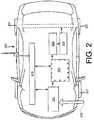
- FIG. 2is a schematic vehicle diagram showing relevant power systems and communications linkages within the vehicle and between the vehicle and a remote entity;
- FIG. 3is a flowchart illustrating a process of recharge optimization based on data source synergy
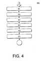
- FIG. 4is a flowchart illustrating a process for establishing and utilizing user alerts to allow for a more controlled user experience in an aspect of the described principles
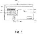
- FIG. 5is a simplified user interface view showing a user display associated with an exemplary configuration application.
- the inventionis directed to a system and method for improving electric-powered driving range for plug-in hybrid-electric and electric vehicles, thus reducing vehicle operating costs and enhancing user convenience.
- the systemidentifies the best time, duration and location to charge an electric vehicle to save cost and use energy efficiently. For example, based on historical driving patterns that may be prerecorded and are used for identification, the system is able to identify the charging needs of the vehicle on-board energy storage system, identify local charging stations within proximity of vehicle, optimize times and places to charge, suggest route changes to the driver, and display information to the driver including alerts based on configured thresholds.
- systemis able to trigger an automatic charge management algorithm based, for example, on a determined least costly time of day to charge the vehicle.
- systemis enabled to deliver information to the user through multiple channels and to allow the user to locally or remotely initiate actions based on alerts.
- the systemallows the user to operate his or her vehicle in a more economical fashion by ensuring timely and cost effective charging, and by allowing the user to more readily appreciate the operating cost differential between different proportions of electric-only use.
- the useris also assisted in locating charging stations.
- the systemleverages data associated with a drivers' electronic calendar, and combines this data with information regarding charging station locations, charging history/behavior, communication capability associated with the vehicle (either wired or wireless) and other enablers to ensure that there is enough charge to drive the vehicle on its next trip.
- an algorithmcombines data regarding driving habits with data from the driver's electronic calendar to create a pattern for the electric vehicle. On a given driving day, based on driving history and input from the electronic calendar a record is created reflecting the expected amount of time before the next drive, when the next drive is to occur, the optimal charging time, how long the drive would be before being near a charging station, and so on. Because it is based on data that it specific to the driver and accounts for the capabilities of the vehicle, such records are unique to the driver and the vehicle.
- geo-coding of main charging stationsallows for a trigger to be set within the vehicle when the vehicle comes within a predetermined proximity of a certain charging station (home, office, etc.).
- the systemdetermines if the current time approximately matches a time that the vehicle has historically been charged. If the location and time match, then the driver's electronic calendar may be queried for the next driving event, and the location of the destination and duration of the drive are determined. The resulting information is matched against the amount of charge left in the vehicle's on-board energy storage system to compute the time for recharging the system.
- Combining these abilitiesallows the system to notify the driver if the vehicle will be ready for the expected next drive, and if not, to ensure that the vehicle becomes ready. If the driver has chosen to recharge when it's cheaper to do so, the recharging may start earlier to allow for complete recharge. In some cases, there will not be sufficient time to charge the vehicle to the necessary level, and in such a case, the customer is sent an alert so that they are aware that there will be insufficient charge to complete the drive on electric power alone.
- FIG. 1there is shown an example of a communication system 100 that may be used with the present method and generally includes a vehicle 102 , a wireless carrier system 104 , a land network 106 and a call center 108 .
- a communication system 100that may be used with the present method and generally includes a vehicle 102 , a wireless carrier system 104 , a land network 106 and a call center 108 .
- the overall architecture, setup and operation, as well as the individual components of a system such as that shown hereare generally known in the art.
- the following paragraphssimply provide a brief overview of one such exemplary information system 100 ; however, other systems not shown here could employ the present method as well.
- Vehicle 102is preferably a mobile vehicle such as a motorcycle, car, truck, recreational vehicle (RV), boat, plane, etc., and is equipped with suitable hardware and software that enables it to communicate over system 100 .
- vehicle hardware 110is shown generally in FIG. 1 including a telematics unit 114 , a microphone 116 , a speaker 118 and buttons and/or controls 120 connected to the telematics unit 114 .
- Operatively coupled to the telematics unit 114is a network connection or vehicle bus 122 .
- Suitable network connectionsinclude a controller area network (CAN), a media oriented system transfer (MOST), a local interconnection network (LIN), an Ethernet, and other appropriate connections such as those that conform with known ISO, SAE, and IEEE standards and specifications, to name a few.
- CANcontroller area network
- MOSTmedia oriented system transfer
- LINlocal interconnection network
- EthernetEthernet
- other appropriate connectionssuch as those that conform with known ISO, SAE, and IEEE standards and specifications, to name a few.
- the telematics unit 114is an onboard device that provides a variety of services through its communication with the call center 108 , and generally includes an electronic processing device 128 one or more types of electronic memory 130 , a cellular chipset/component 124 , a wireless modem 126 , a dual antenna 160 and a navigation unit containing a GPS chipset/component 132 .
- the wireless modem 126is comprised of a computer program and/or set of software routines executing within processing device 128 .
- the cellular chipset/component 124 and the wireless modem 126may be called the network access device (NAD) 180 of the telematics unit 114 .
- NADnetwork access device
- the telematics unit 114provides too many services to list them all, but several examples include: turn-by-turn directions and other navigation-related services provided in conjunction with the GPS based chipset/component 132 ; airbag deployment notification and other emergency or roadside assistance-related services provided in connection with various crash and or collision sensor interface modules 156 and sensors 158 located throughout the vehicle.
- Infotainment-related serviceswhere music, Web pages, movies, television programs, video games and/or other content is downloaded by an infotainment center 136 operatively connected to the telematics unit 114 via vehicle bus 122 and audio bus 112 .
- downloaded contentis stored for current or later playback.
- telematics unit 114is capable of offering. It is anticipated that telematics unit 114 include a number of known components in addition to those listed above.
- Vehicle communicationspreferably use radio transmissions to establish a voice channel with wireless carrier system 104 so that both voice and data transmissions can be sent and received over the voice channel.
- Vehicle communicationsare enabled via the cellular chipset/component 124 for voice communications and a wireless modem 126 for data transmission.
- wireless modem 126applies some type of encoding or modulation to convert the digital data so that it can communicate through a vocoder or speech codec incorporated in the cellular chipset/component 124 . Any suitable encoding or modulation technique that provides an acceptable data rate and bit error can be used with the present method.
- Dual mode antenna 160services the GPS chipset/component and the cellular chipset/component.
- Microphone 116provides the driver or other vehicle occupant with a means for inputting verbal or other auditory commands, and can be equipped with an embedded voice processing unit utilizing a human/machine interface (HMI) technology known in the art.
- speaker 118provides verbal output to the vehicle occupants and can be either a stand-alone speaker specifically dedicated for use with the telematics unit 114 or can be part of a vehicle audio component 154 .
- microphone 116 and speaker 118enable vehicle hardware 110 and call center 108 to communicate with the occupants through audible speech.
- the vehicle hardwarealso includes one or more buttons or controls 120 for enabling a vehicle occupant to activate or engage one or more of the vehicle hardware components 110 .
- one of the buttons 120can be an electronic push button used to initiate voice communication with call center 108 (whether it be a live advisor 148 or an automated call response system).
- one of the buttons 120can be used to initiate emergency services.
- the audio component 154is operatively connected to the vehicle bus 122 and the audio bus 112 .
- the audio component 154receives analog information, rendering it as sound, via the audio bus 112 .
- Digital informationis received via the vehicle bus 122 .
- the audio component 154provides AM and FM radio, CD, DVD, and multimedia functionality independent of the infotainment center 136 .
- Audio component 154may contain a speaker system, or may utilize speaker 118 via arbitration on vehicle bus 122 and/or audio bus 112 .
- the vehicle crash and/or collision detection sensor interface 156are operatively connected to the vehicle bus 122 .
- the crash sensors 158provide information to the telematics unit 114 via the crash and/or collision detection sensor interface 156 regarding the severity of a vehicle collision, such as the angle of impact and the amount of force sustained.
- Vehicle sensors 162connected to various sensor interface modules 134 are operatively connected to the vehicle bus 122 .
- Example vehicle sensorsinclude but are not limited to gyroscopes, accelerometers, magnetometers, emission detection and/or control sensors, and the like.
- Example sensor interface modules 134include power train control, climate control, and body control, to name but a few.
- Wireless carrier system 104is preferably a cellular telephone system or any other suitable wireless system that transmits signals between the vehicle hardware 110 and land network 106 .
- wireless carrier system 104includes one or more cell towers 138 , base stations and/or mobile switching centers (MSCs) 140 , as well as any other networking components required to connect the wireless system 104 with land network 106 .
- a component in the mobile switching centermay include a remote data server 180 .
- various cell tower/base station/MSC arrangementsare possible and could be used with wireless system 104 .
- a base station and a cell towercould be co-located at the same site or they could be remotely located, and a single base station could be coupled to various cell towers or various base stations could be coupled with a single MSC, to but a few of the possible arrangements.
- a speech codec or vocoderis incorporated in one or more of the base stations, but depending on the particular architecture of the wireless network, it could be incorporated within a Mobile Switching Center or some other network components as well.
- Land network 106can be a conventional land-based telecommunications network that is connected to one or more landline telephones and connects wireless carrier network 104 to call center 108 .
- land network 106can include a public switched telephone network (PSTN) and/or an Internet protocol (IP) network, as is appreciated by those skilled in the art.
- PSTNpublic switched telephone network
- IPInternet protocol
- one or more segments of the land network 106can be implemented in the form of a standard wired network, a fiber or other optical network, a cable network, other wireless networks such as wireless local networks (WLANs) or networks providing broadband wireless access (BWA), or any combination thereof.
- WLANswireless local networks
- BWAbroadband wireless access
- Call Center (OCC) 108is designed to provide the vehicle hardware 110 with a number of different system back-end functions and, according to the example shown here, generally includes one or more switches 142 , servers 144 , databases 146 , live advisors 148 , as well as a variety of other telecommunication and computer equipment 150 that is known to those skilled in the art. These various call center components are preferably coupled to one another via a network connection or bus 152 , such as the one previously described in connection with the vehicle hardware 110 .
- Switch 142which can be a private branch exchange (PBX) switch, routes incoming signals so that voice transmissions are usually sent to either the live advisor 148 or an automated response system, and data transmissions are passed on to a modem or other piece of equipment 150 for demodulation and further signal processing.
- PBXprivate branch exchange
- the modem 150preferably includes an encoder, as previously explained, and can be connected to various devices such as a server 144 and database 146 .
- database 146could be designed to store subscriber profile records, subscriber behavioral patterns, or any other pertinent subscriber information.
- the illustrated examplehas been described as it would be used in conjunction with a manned call center 108 , it will be appreciated that the call center 108 can be any central or remote facility, manned or unmanned, mobile or fixed, to or from which it is desirable to exchange voice and data.
- the telematics unit 114 and associated componentsare associated in an implementation of the invention with a vehicle 102 .
- the vehicle 102is a plug-in hybrid-electric or electric vehicle.
- FIG. 2is a vehicle schematic showing the components of the vehicle of interest with the respect to the disclosed principles and the manner in which the components may be interrelated to execute those principles. It will be appreciated, however, that the illustrated architecture is merely an example, and that the disclosed principles do not require that the vehicle be configured precisely as shown.
- the vehicle 200( 102 ) includes an electrical energy storage system 201 , e.g., a battery of suitable voltage and capacity.
- the electrical energy storage system 201is conductively linkable, e.g., via a controller 203 , to an electrical drive unit 205 , e.g., an electrical motor or motors.
- the electrical energymay be modulated, voltage-modified, or otherwise modified by the controller 203 as needed to drive the electrical drive unit 205 .
- the electrical drive unit 205is linked or linkable to a ground engaging drive, typically including one or more wheels 207 .
- a plug interface 219is provided.
- the plug interface 219is linked to the electrical energy storage system 201 via a charge controller 221 .
- the telematics unit 214( 114 ) is adapted to receive information from a remote source as discussed above to convey data regarding vehicle systems and to facilitate alerts when appropriate.
- the inventionis directed to a system and method for improving electric-power driving range for plug-in hybrid-electric and electric vehicles, thus reducing vehicle operating costs, lowering vehicle-based carbon emissions, and enhancing user convenience.
- the systemcreates a synergy of data sources by combining information from numerous disparate sources to provide services that would not be possible with any one source.
- the systemidentifies the best time, duration and location to charge an electric vehicle to save cost and use energy efficiently. For example, based on historical driving patterns that may be prerecorded and are used for identification, the system is able to identify the charging needs of the vehicle on-board energy storage system, identify local charging stations near vehicle, optimize times and places to charge in real time, suggest route changes to the driver, and display information to the driver including alerts based on configured thresholds.
- the needs of the vehicle, the schedule of to user, the locations of charging facilities and the time-varying cost of electricityare combined in one aspect to provide the user with the lowest cost and most environmentally sound experience available with their vehicle.
- FIG. 3shows a process of recharge optimization based on data source synergy.
- the process 300may run locally or remotely from the vehicle 200 , e.g., in the vehicle telematics unit 114 or associated hardware, or at a remote server connected wirelessly to the telematics unit 114 .
- the process 300may be run on a regular interval or may be triggered by a battery charge threshold, e.g., if the charge is below 90% of capacity, the process runs.
- a battery charge thresholde.g., if the charge is below 90% of capacity
- data collection operations relative to vehicle parameterssuch as location, charge state, etc., are taken locally, and may either be processed locally or transmitted to a remote entity, e.g., a server, for processing.
- a remote entitye.g., a server
- the telematics unitaccesses prerecorded historical driving patterns.
- the telematics unitidentifies likely travel patterns within a forward looking time window at stage 303 .
- the duration of the time windowis not critical, but in one aspect, the time window may be 24 hours.
- the process 300moves to stage 305 , wherein the telematics unit accesses the user's calendar to identify upcoming travel.
- the calendarindicates travel, then the estimate based on the calendar is used for subsequent processing, whereas if the calendar does not indicate travel, then the estimate based on historical patterns is used.
- the relevant data selected in stage 307is processed to provide an estimate of vehicle charge needs.
- the distance and driving type associated with the estimated routeare calculated and are used identify the charging needs of the vehicle on-board energy storage system. For example, rough roads and roads having frequent stops and starts will require more energy per distance traveled.
- the systemmay take this into account at stage 311 to identify charging opportunities and associated locations.
- the systemmay also suggest minor route changes to provide charging opportunities. For example, if a user usually parks at his or her office and there is no known charging facility at that location, the system may suggest that the user instead park at a location a block away that does have a charging facility. Similarly, if the upcoming travel is a two day trip to reach a distant destination, the system may suggest a route modification such that the overnight stop occurs at a known charging facility.
- the systemmay modify the instructions to the driver based on the time-varying cost of electricity from the grid at stage 313 . For example, if the expected trip is a round-trip to the user's place of work, with one leg in the morning and one leg in the evening, and electricity from the grid costs less per kilowatthour during nonworking hours, the system may advise the user to fully charge the vehicle at home to support a full round trip even though the user would have been able to charge the vehicle at the workplace after the first leg of the round trip.
- the processconveys to the user a user instruction set having instructions for charging times and driving routes where appropriate.
- the instructionsmay be conveyed to the user in the vehicle by audio means such as via vehicle speakers or by visual means such as on a telematics or heads-up display.
- the instructionsmay additionally or alternatively be provided to the user remotely by being transmitted from the telematics unit over the wireless network to a wireless device associated with the user, such as a cell phone, personal data device, laptop computer, desktop computer, etc.
- a wireless device associated with the usersuch as a cell phone, personal data device, laptop computer, desktop computer, etc.
- a useris able to configure and receive alert messages triggered through user-set thresholds. For example, a user that operates their vehicle primarily within a city that has a diameter of roughly 20 miles may wish to ensure that their vehicle on-board energy storage system is charged any time that its charge state will only support a lesser distance and the vehicle is near a known charging facility, regardless of cost and regardless of historically predicted or planned driving activities.
- FIG. 4illustrates a process 400 for establishing and utilizing user alerts to allow for a more controlled user experience.
- the process 400may be executed locally to the vehicle, e.g., through a user interface associated with an in-vehicle navigation set or telematics unit, or may be executed remotely, e.g., via a user interface associated with a remote device accessible to the user.
- the output of the process to the usermay occur locally (e.g., at the in-vehicle display), remotely (e.g., at the user's remote device), or both.
- a user displayis provided to the user via a configuration application running preferably at the location at which the user display is rendered although it is contemplated that the application may run remotely from the site of user input as well.
- the user displayis in accordance with the exemplary configuration 500 shown in FIG. 5 , which will be discussed later.
- the userselects a vehicle to configure at stage 403 to begin the user input portion of the configuration process.
- the usermay select one of several electric vehicles owned by the user, with configuration of all vehicles carried out by sequentially iterating through the process 400 .
- the userthen optionally activates and selects parameters for a proximity alert at stage 405 , i.e., an alert that informs the user of the presence of a nearby charging station.
- the selected parametermay be a proximity within which the user would like to be notified. If the user has activated the proximity alert at stage 403 , the user may optionally configure the proximity distance to scale with remaining charge capacity at stage 407 , so that the system will more liberally recommend charge sites as the need for charging increases.
- the usermay elect, via the user interface, to activate one or more capacity alerts, i.e., alerts that notify the user when the vehicle battery capacity has diminished below a user-set threshold.
- the usermay indicate completion of the configuration at stage 411 whereupon the input selections and parameters are stored for use by the alerting application.
- the valuesmay be stored remotely or locally relative to the vehicle or the user device, as long as they remain accessible to the alerting application from the platform upon which it runs.
- the exemplary user display configuration 500 shown in FIG. 5includes a vehicle identification field 501 to allow the user to identify the vehicle for which the configuration activity is being executed.
- a usermay have multiple vehicles, and they may serve different uses, have different capabilities, and have different charging needs.
- the exemplary user interfacealso includes a proximity-based alert field 503 and a capacity-based alert field 505 .
- An activation check box field 509 , 511may be associated with each to turn the associated alerting function on or off.
- the useremploys the proximity-based alert field 503 to configure, via pull-down options or input options, one or more alerts to alert the user when the vehicle is within a predetermined proximity of a known charging station.
- the userselects the predetermined proximity and in a further aspect, the predetermined proximity scales or deactivates in relation to the charge state of the vehicle.
- a user-selectable check field 507may be provided for this purpose. Thus, for example, in this aspect if the user-selectable check field 507 is selected, and if the vehicle battery is relatively fully charged, e.g., within 10% of capacity, then proximity-based alerting is suppressed.
- the capacity-based alert fieldallows the user to select, in a similar manner, one or more alarm thresholds at which the user is prompted to recharge the battery.
- the prompts at the various thresholdmay vary based on urgency. For example, if the user sets a 50% remaining threshold and a 10% remaining threshold, an alert associated with falling past the 10% threshold may be more noticeable (e.g., louder, brighter, more persistent) than an alert associated with passing the 50% threshold.
- alertsmay be given within the vehicle, or via the user's remote device, or both.
- the usermay select a field such as the completion field 513 .
- the parameters entered by the userare stored for use by the alerting application. Triggers to later run the alerting application may include a change of a predetermined increment in location, battery charge, etc.
- the usermay be directed to geo-coded charging stations in certain circumstances.
- any method of generating a list of charging stations and their locations and capabilitiesmay be used, in one aspect, the locations and capabilities of charging stations are learned by the system as such stations are used.
- the systemdetermines the duration of the charge action and the location of the charging facility. This data collection may be made by the telematics unit 214 in concert with the charge controller 221 or otherwise as appropriate.
Landscapes
- Engineering & Computer Science (AREA)
- Power Engineering (AREA)
- Transportation (AREA)
- Mechanical Engineering (AREA)
- Electric Propulsion And Braking For Vehicles (AREA)
Abstract
Description
Claims (18)
Priority Applications (2)
| Application Number | Priority Date | Filing Date | Title |
|---|---|---|---|
| US12/781,394US8615355B2 (en) | 2010-05-17 | 2010-05-17 | Multifactor charging for electric vehicles |
| CN201110127404.3ACN102248921B (en) | 2010-05-17 | 2011-05-17 | Multi-factor charging for electric vehicles |
Applications Claiming Priority (1)
| Application Number | Priority Date | Filing Date | Title |
|---|---|---|---|
| US12/781,394US8615355B2 (en) | 2010-05-17 | 2010-05-17 | Multifactor charging for electric vehicles |
Publications (2)
| Publication Number | Publication Date |
|---|---|
| US20110282527A1 US20110282527A1 (en) | 2011-11-17 |
| US8615355B2true US8615355B2 (en) | 2013-12-24 |
Family
ID=44912472
Family Applications (1)
| Application Number | Title | Priority Date | Filing Date |
|---|---|---|---|
| US12/781,394Active2032-01-22US8615355B2 (en) | 2010-05-17 | 2010-05-17 | Multifactor charging for electric vehicles |
Country Status (2)
| Country | Link |
|---|---|
| US (1) | US8615355B2 (en) |
| CN (1) | CN102248921B (en) |
Cited By (14)
| Publication number | Priority date | Publication date | Assignee | Title |
|---|---|---|---|---|
| US20120158915A1 (en)* | 2010-12-21 | 2012-06-21 | Samsung Electronics Co., Ltd. | Apparatus and method of controlling operation of cleaner |
| US8725330B2 (en) | 2010-06-02 | 2014-05-13 | Bryan Marc Failing | Increasing vehicle security |
| US9610853B1 (en)* | 2015-09-24 | 2017-04-04 | Ford Global Technologies, Llc | Identification of acceptable vehicle charge stations |
| US9739624B2 (en) | 2015-12-22 | 2017-08-22 | GM Global Technology Operations LLC | Vehicle power management utilizing operator schedule data |
| US10650621B1 (en) | 2016-09-13 | 2020-05-12 | Iocurrents, Inc. | Interfacing with a vehicular controller area network |
| US10762453B2 (en) | 2017-09-15 | 2020-09-01 | Honda Motor Co., Ltd. | Methods and systems for monitoring a charging pattern to identify a customer |
| US11260762B2 (en) | 2018-04-30 | 2022-03-01 | Ford Global Technologies, Llc | Auxiliary battery charging systems and methods for electrified vehicles |
| US11441917B2 (en) | 2019-08-14 | 2022-09-13 | Honda Motor Co., Ltd. | System and method for adjusting an electric vehicle charging speed |
| US11498447B2 (en) | 2020-12-22 | 2022-11-15 | Ford Global Technologies, Llc | Vehicle to vehicle charge cable acquisition |
| US11498452B2 (en) | 2019-11-11 | 2022-11-15 | Ford Global Technologies, Llc | Vehicle charging control systems and methods |
| US11685282B2 (en) | 2021-02-18 | 2023-06-27 | Ford Global Technologies, Llc | Electric vehicle charging aggregation |
| US11926243B2 (en) | 2020-09-08 | 2024-03-12 | Ford Global Technologies, Llc | Confidence-based vehicle charge control |
| US12117498B2 (en) | 2019-08-14 | 2024-10-15 | Honda Motor Co., Ltd. | System and method for presenting electric vehicle charging options based on a predicted charging speed |
| US12420665B2 (en) | 2023-10-25 | 2025-09-23 | Textron Innovations Inc. | Selective early charge termination |
Families Citing this family (72)
| Publication number | Priority date | Publication date | Assignee | Title |
|---|---|---|---|---|
| KR101648348B1 (en) | 2010-04-06 | 2016-08-16 | 삼성전자주식회사 | Robot cleaning system and control method that equip wireless electric power charge function |
| US9692259B2 (en) | 2010-06-29 | 2017-06-27 | International Business Machines Corporation | Power management and priority charging assignments |
| US9172116B2 (en)* | 2010-08-27 | 2015-10-27 | General Motors Llc. | System and method for remote management of electric vehicle charge profiles |
| JP5506943B2 (en)* | 2010-10-05 | 2014-05-28 | 三菱電機株式会社 | Charge control device |
| US8849499B2 (en)* | 2011-01-06 | 2014-09-30 | Ford Global Technologies, Llc | Methods and systems for monitoring a vehicle's energy source |
| US8502498B2 (en)* | 2011-01-19 | 2013-08-06 | General Motors Llc | Localized charging of electric vehicles |
| US9527398B2 (en)* | 2011-01-20 | 2016-12-27 | General Motors Llc | Virtual charge for electric vehicles |
| US20120239594A1 (en)* | 2011-03-17 | 2012-09-20 | John Christopher Boot | Apparatus and methods for providing demand response information |
| US9751424B2 (en)* | 2011-07-14 | 2017-09-05 | Ford Global Technologies, Llc | Method and system for determining a target state of charge to charge a battery in a vehicle using external electric power |
| JP2014529118A (en) | 2011-07-26 | 2014-10-30 | ゴゴロ インク | Apparatus, method and article for providing information relating to the availability of a power storage device in a power storage device collection, charging and distribution machine |
| US10186094B2 (en) | 2011-07-26 | 2019-01-22 | Gogoro Inc. | Apparatus, method and article for providing locations of power storage device collection, charging and distribution machines |
| EP2737598A4 (en)* | 2011-07-26 | 2015-09-02 | APPARATUS, METHOD AND ARTICLE FOR RESERVING POWER STORAGE DEVICES AT COLLECTION, CHARGING AND DISTRIBUTION MACHINES OF POWER STORAGE DEVICES | |
| TWI517078B (en) | 2011-07-26 | 2016-01-11 | 睿能創意公司 | Apparatus, method and article for a power storage device compartment |
| ES2701745T3 (en) | 2011-07-26 | 2019-02-25 | Gogoro Inc | Apparatus, method and article for the redistribution of energy storage devices, such as batteries, between collection, loading and distribution machines |
| ES2939174T3 (en) | 2011-07-26 | 2023-04-19 | Gogoro Inc | Dynamic limitation of vehicle operation for a better economy of efforts |
| ES2967056T3 (en) | 2011-07-26 | 2024-04-25 | Gogoro Inc | Apparatus, method and article for authentication, security and control of energy storage devices, such as batteries |
| TWI553999B (en) | 2011-07-26 | 2016-10-11 | 睿能創意公司 | Portable energy storage device collection, charging and dispensing machine and method of operation thereof, and non-transitory computer readable medium for storing instructions |
| US9437058B2 (en) | 2011-07-26 | 2016-09-06 | Gogoro Inc. | Dynamically limiting vehicle operation for best effort economy |
| JP5454537B2 (en)* | 2011-09-22 | 2014-03-26 | 株式会社デンソー | Electric vehicle charging control system |
| FR2980887B1 (en)* | 2011-09-30 | 2021-11-12 | Ier Systems | METHOD AND SYSTEM FOR SECURING A VEHICLE OFFERED FOR RENTAL, AND INSTALLATION FOR RENTAL OF VEHICLES IMPLEMENTING SUCH SYSTEM OR PROCESS. |
| JP5499014B2 (en)* | 2011-12-20 | 2014-05-21 | 本田技研工業株式会社 | In-vehicle battery management system |
| US8849742B2 (en) | 2012-01-24 | 2014-09-30 | Ford Global Technologies, Llc | Method and apparatus for providing charging state alerts |
| JP6041124B2 (en)* | 2012-05-31 | 2016-12-07 | 日本電気株式会社 | Information processing system, information processing method, mobile communication terminal, control method and control program for mobile communication terminal, server, server control method and control program |
| US9118183B2 (en)* | 2012-06-07 | 2015-08-25 | Schneider Electric USA, Inc. | Auto detection of vehicle type connected to an EVSE |
| US20150165918A1 (en)* | 2012-07-04 | 2015-06-18 | Nec Corporation | Charging system control apparatus, program, and control method |
| EP2894436A4 (en)* | 2012-09-03 | 2016-04-27 | Hitachi Ltd | CHARGING ASSISTING SYSTEM AND LOADING ASSISTING METHOD FOR ELECTRIC VEHICLE |
| CN103715725B (en)* | 2012-09-29 | 2017-03-01 | 日电(中国)有限公司 | Charging system of electric powercar and method |
| BR112015011290A2 (en) | 2012-11-16 | 2017-07-11 | Gogoro Inc | apparatus, method and article for vehicle turn signaling |
| JP6788934B2 (en)* | 2013-03-13 | 2020-11-25 | ゴゴロ インク | Devices, methods, and articles for providing information about a vehicle via a mobile device. |
| EP2973937B1 (en) | 2013-03-15 | 2020-06-03 | Gogoro Inc. | Modular system for collection and distribution of electric storage devices |
| US10121158B2 (en)* | 2013-04-26 | 2018-11-06 | General Motors Llc | Optimizing vehicle recharging to limit use of electricity generated from non-renewable sources |
| US9440549B2 (en)* | 2013-05-03 | 2016-09-13 | Semmaconnect Inc. | System and method for detecting vehicle proximity in an electrical vehicle supply equipment |
| US9457677B2 (en) | 2013-09-30 | 2016-10-04 | Elwha Llc | User interface to employment related information center associated with communication and control system and method for wireless electric vehicle electrical energy transfer |
| US9412515B2 (en) | 2013-09-30 | 2016-08-09 | Elwha, Llc | Communication and control regarding wireless electric vehicle electrical energy transfer |
| US10011180B2 (en) | 2013-09-30 | 2018-07-03 | Elwha, Llc | Communication and control system and method regarding electric vehicle charging equipment for wireless electric vehicle electrical energy transfer |
| US20150091503A1 (en)* | 2013-09-30 | 2015-04-02 | Elwha Llc | Communication and Control System and Method Regarding Electric Vehicle Charging Equipment for Wireless Electric Vehicle Electrical Energy Transfer |
| US10093194B2 (en) | 2013-09-30 | 2018-10-09 | Elwha Llc | Communication and control system and method regarding electric vehicle for wireless electric vehicle electrical energy transfer |
| WO2015094807A1 (en)* | 2013-12-16 | 2015-06-25 | Contour Hardening, Inc. | System and method for control of an electric vehicle |
| ES2721769T3 (en) | 2014-08-11 | 2019-08-05 | Gogoro Inc | Multidirectional electrical connector and plug |
| TWI671219B (en) | 2014-09-04 | 2019-09-11 | 睿能創意公司 | Method for operating portable energy storage charging and two-way distribution system |
| US20160305791A1 (en)* | 2015-04-14 | 2016-10-20 | Ford Global Technologies, Llc | Vehicle energy alert systems and methods |
| JP6887718B2 (en) | 2015-06-05 | 2021-06-16 | ゴゴロ インク | How to determine a particular type of vehicle and electric vehicle load |
| US10737577B2 (en)* | 2015-11-04 | 2020-08-11 | Ford Global Technologies, Llc | Control strategy for charging electrified vehicle over multiple locations of a drive route |
| KR20170069092A (en)* | 2015-12-10 | 2017-06-20 | 현대자동차주식회사 | Audio video navigation device and method for providing charging station information using the audio video navigation device |
| DE102015226147B4 (en)* | 2015-12-21 | 2023-08-31 | Bayerische Motoren Werke Aktiengesellschaft | Method, processor device, motor vehicle with such a processor device and telematics system for the automatic configuration of telematic data transmissions of the motor vehicle |
| US10124725B2 (en)* | 2016-03-01 | 2018-11-13 | Ford Global Technologies, Llc | Customizable vehicle charge status tones |
| US20170308948A1 (en)* | 2016-04-25 | 2017-10-26 | Ford Global Technologies, Llc | Electrified vehicle activity center ranking |
| CN106627223A (en)* | 2016-12-20 | 2017-05-10 | 武汉磐固科技有限责任公司 | Battery intelligent management system |
| US10486704B2 (en) | 2017-08-08 | 2019-11-26 | Ford Global Technologies, Llc | Powertrain fault management |
| US10464564B2 (en) | 2017-08-08 | 2019-11-05 | Ford Global Technologies, Llc | Powertrain fault management |
| US10401853B2 (en)* | 2017-08-08 | 2019-09-03 | Ford Global Technologies, Llc | Powertrain fault management |
| US11433872B2 (en)* | 2017-11-07 | 2022-09-06 | Waymo Llc | Thermal management of hybrid vehicle |
| GB2568465A (en)* | 2017-11-13 | 2019-05-22 | Jaguar Land Rover Ltd | Determining a charging requirement for an energy storage means of a vehicle |
| WO2019139633A1 (en) | 2018-01-11 | 2019-07-18 | Lancium Llc | Method and system for dynamic power delivery to a flexible growcenter using unutilized energy sources |
| US10761535B2 (en)* | 2018-08-21 | 2020-09-01 | GM Global Technology Operations LLC | Intelligent vehicle navigation systems, methods, and control logic for multi-lane separation and trajectory extraction of roadway segments |
| US11025060B2 (en) | 2018-09-14 | 2021-06-01 | Lancium Llc | Providing computational resource availability based on power-generation signals |
| US11031787B2 (en) | 2018-09-14 | 2021-06-08 | Lancium Llc | System of critical datacenters and behind-the-meter flexible datacenters |
| US10873211B2 (en) | 2018-09-14 | 2020-12-22 | Lancium Llc | Systems and methods for dynamic power routing with behind-the-meter energy storage |
| US11016553B2 (en) | 2018-09-14 | 2021-05-25 | Lancium Llc | Methods and systems for distributed power control of flexible datacenters |
| US11031813B2 (en) | 2018-10-30 | 2021-06-08 | Lancium Llc | Systems and methods for auxiliary power management of behind-the-meter power loads |
| US20200175614A1 (en)* | 2018-11-29 | 2020-06-04 | International Business Machines Corporation | Electric vehicle charging station having reverse tiered discount incentive |
| US11586159B2 (en)* | 2019-01-28 | 2023-02-21 | GM Global Technology Operations LLC | Machine learning method and system for executing remote commands to control functions of a vehicle |
| US11128165B2 (en)* | 2019-02-25 | 2021-09-21 | Lancium Llc | Behind-the-meter charging station with availability notification |
| US11397999B2 (en) | 2019-08-01 | 2022-07-26 | Lancium Llc | Modifying computing system operations based on cost and power conditions |
| US11868106B2 (en) | 2019-08-01 | 2024-01-09 | Lancium Llc | Granular power ramping |
| US11332026B2 (en)* | 2019-09-03 | 2022-05-17 | GM Global Technology Operations LLC | System and method for unlocking a power chord during charging of a vehicle based on a user location |
| US10618427B1 (en) | 2019-10-08 | 2020-04-14 | Lancium Llc | Behind-the-meter branch loads for electrical vehicle charging |
| US11016458B2 (en) | 2019-10-28 | 2021-05-25 | Lancium Llc | Methods and systems for adjusting power consumption based on dynamic power option agreement |
| US11042948B1 (en) | 2020-02-27 | 2021-06-22 | Lancium Llc | Computing component arrangement based on ramping capabilities |
| WO2022036239A1 (en) | 2020-08-14 | 2022-02-17 | Lancium Llc | Power aware scheduling |
| GR1010201B (en)* | 2021-04-23 | 2022-03-21 | Inlecom Innovation Astiki Mi Kerdoskopiki Etaireia, | Electric vehicle charging dynamic scheduling |
| CN113306448A (en)* | 2021-06-17 | 2021-08-27 | 江苏云快充新能源科技有限公司 | Charging prompting method, device, equipment and storage medium |
Citations (7)
| Publication number | Priority date | Publication date | Assignee | Title |
|---|---|---|---|---|
| US6181991B1 (en)* | 1998-04-28 | 2001-01-30 | Honda Giken Kogyo Kabushiki Kaisha | Electric vehicle sharing system |
| US20110022254A1 (en)* | 2009-07-24 | 2011-01-27 | Michael Johas Teener | Method and system for location assisted power management |
| US8155867B2 (en)* | 2009-01-29 | 2012-04-10 | General Motors Llc | System and method for communicating with a vehicle about then-current vehicle operating conditions using a telematics unit |
| US8170737B2 (en)* | 2009-04-30 | 2012-05-01 | GM Global Technology Operations LLC | Method of controlling vehicle powertrain and vehicle control system |
| US8301323B2 (en)* | 2008-03-31 | 2012-10-30 | Toyota Jidosha Kabushiki Kaisha | Navigation system, hybrid vehicle with same, and method of searching for route for hybrid vehicle |
| US8315788B2 (en)* | 2010-05-19 | 2012-11-20 | Ford Global Technologies, Llc | Method and system for vehicle refueling |
| US8326478B2 (en)* | 2008-03-31 | 2012-12-04 | Toyota Jidosha Kabushiki Kaisha | Hybrid vehicle and method of controlling the same |
Family Cites Families (3)
| Publication number | Priority date | Publication date | Assignee | Title |
|---|---|---|---|---|
| IT1250897B (en)* | 1991-12-24 | 1995-04-21 | Fiat Auto Spa | AUTONOMY INDICATOR DEVICE FOR A ACCUMULATOR VEHICLE. |
| JP4882946B2 (en)* | 2007-09-28 | 2012-02-22 | 三菱自動車工業株式会社 | Electricity cost calculation device |
| CN101318489B (en)* | 2008-05-07 | 2011-09-21 | 中国科学院电工研究所 | Vehicle battery management system control method |
- 2010
- 2010-05-17USUS12/781,394patent/US8615355B2/enactiveActive
- 2011
- 2011-05-17CNCN201110127404.3Apatent/CN102248921B/enactiveActive
Patent Citations (7)
| Publication number | Priority date | Publication date | Assignee | Title |
|---|---|---|---|---|
| US6181991B1 (en)* | 1998-04-28 | 2001-01-30 | Honda Giken Kogyo Kabushiki Kaisha | Electric vehicle sharing system |
| US8301323B2 (en)* | 2008-03-31 | 2012-10-30 | Toyota Jidosha Kabushiki Kaisha | Navigation system, hybrid vehicle with same, and method of searching for route for hybrid vehicle |
| US8326478B2 (en)* | 2008-03-31 | 2012-12-04 | Toyota Jidosha Kabushiki Kaisha | Hybrid vehicle and method of controlling the same |
| US8155867B2 (en)* | 2009-01-29 | 2012-04-10 | General Motors Llc | System and method for communicating with a vehicle about then-current vehicle operating conditions using a telematics unit |
| US8170737B2 (en)* | 2009-04-30 | 2012-05-01 | GM Global Technology Operations LLC | Method of controlling vehicle powertrain and vehicle control system |
| US20110022254A1 (en)* | 2009-07-24 | 2011-01-27 | Michael Johas Teener | Method and system for location assisted power management |
| US8315788B2 (en)* | 2010-05-19 | 2012-11-20 | Ford Global Technologies, Llc | Method and system for vehicle refueling |
Cited By (24)
| Publication number | Priority date | Publication date | Assignee | Title |
|---|---|---|---|---|
| US11186192B1 (en) | 2010-06-02 | 2021-11-30 | Bryan Marc Failing | Improving energy transfer with vehicles |
| US8725330B2 (en) | 2010-06-02 | 2014-05-13 | Bryan Marc Failing | Increasing vehicle security |
| US8841881B2 (en) | 2010-06-02 | 2014-09-23 | Bryan Marc Failing | Energy transfer with vehicles |
| US9114719B1 (en) | 2010-06-02 | 2015-08-25 | Bryan Marc Failing | Increasing vehicle security |
| US9393878B1 (en) | 2010-06-02 | 2016-07-19 | Bryan Marc Failing | Energy transfer with vehicles |
| US10124691B1 (en) | 2010-06-02 | 2018-11-13 | Bryan Marc Failing | Energy transfer with vehicles |
| US9717384B2 (en)* | 2010-12-21 | 2017-08-01 | Samsung Electronics Co., Ltd | Apparatus and method of controlling operation of cleaner |
| US20120158915A1 (en)* | 2010-12-21 | 2012-06-21 | Samsung Electronics Co., Ltd. | Apparatus and method of controlling operation of cleaner |
| US9610853B1 (en)* | 2015-09-24 | 2017-04-04 | Ford Global Technologies, Llc | Identification of acceptable vehicle charge stations |
| US9739624B2 (en) | 2015-12-22 | 2017-08-22 | GM Global Technology Operations LLC | Vehicle power management utilizing operator schedule data |
| US11232655B2 (en) | 2016-09-13 | 2022-01-25 | Iocurrents, Inc. | System and method for interfacing with a vehicular controller area network |
| US10650621B1 (en) | 2016-09-13 | 2020-05-12 | Iocurrents, Inc. | Interfacing with a vehicular controller area network |
| US10762453B2 (en) | 2017-09-15 | 2020-09-01 | Honda Motor Co., Ltd. | Methods and systems for monitoring a charging pattern to identify a customer |
| US11260762B2 (en) | 2018-04-30 | 2022-03-01 | Ford Global Technologies, Llc | Auxiliary battery charging systems and methods for electrified vehicles |
| US11441917B2 (en) | 2019-08-14 | 2022-09-13 | Honda Motor Co., Ltd. | System and method for adjusting an electric vehicle charging speed |
| US12117498B2 (en) | 2019-08-14 | 2024-10-15 | Honda Motor Co., Ltd. | System and method for presenting electric vehicle charging options based on a predicted charging speed |
| US12018955B2 (en) | 2019-08-14 | 2024-06-25 | Honda Motor Co., Ltd. | System and method for presenting electric vehicle charging options |
| US11740098B2 (en) | 2019-08-14 | 2023-08-29 | Honda Motor Co., Ltd. | System and method for providing charging options based on electric vehicle operator activities |
| US11920940B2 (en) | 2019-08-14 | 2024-03-05 | Honda Motor Co., Ltd. | System and method for adjusting an electric vehicle charging speed |
| US11498452B2 (en) | 2019-11-11 | 2022-11-15 | Ford Global Technologies, Llc | Vehicle charging control systems and methods |
| US11926243B2 (en) | 2020-09-08 | 2024-03-12 | Ford Global Technologies, Llc | Confidence-based vehicle charge control |
| US11498447B2 (en) | 2020-12-22 | 2022-11-15 | Ford Global Technologies, Llc | Vehicle to vehicle charge cable acquisition |
| US11685282B2 (en) | 2021-02-18 | 2023-06-27 | Ford Global Technologies, Llc | Electric vehicle charging aggregation |
| US12420665B2 (en) | 2023-10-25 | 2025-09-23 | Textron Innovations Inc. | Selective early charge termination |
Also Published As
| Publication number | Publication date |
|---|---|
| CN102248921A (en) | 2011-11-23 |
| CN102248921B (en) | 2014-02-12 |
| US20110282527A1 (en) | 2011-11-17 |
Similar Documents
| Publication | Publication Date | Title |
|---|---|---|
| US8615355B2 (en) | Multifactor charging for electric vehicles | |
| US8718844B2 (en) | Charge notification method for extended range electric vehicles | |
| US8538621B2 (en) | Charge reminder notification to increase electric only efficiency | |
| US9527398B2 (en) | Virtual charge for electric vehicles | |
| US8326470B2 (en) | Remote trigger of an alternate energy source to power a vehicle system | |
| US9529584B2 (en) | System and method for preparing vehicle for remote reflash event | |
| US20120049793A1 (en) | System and method for remote management of electric vehicle charge profiles | |
| CN104786860B (en) | Method and apparatus for electric vehicle route and charging plan | |
| US8565948B2 (en) | Energy consumption comparison method | |
| US8321125B2 (en) | System and method for providing route guidance to a requesting vehicle | |
| US9086285B2 (en) | Automatic detection of parking level in multi-level structure | |
| US10969236B2 (en) | Vehicle route control based on user-provided trip constraints | |
| US8604937B2 (en) | Telematics unit and method for controlling telematics unit for a vehicle | |
| US20120290149A1 (en) | Methods and Apparatus for Selective Power Enablement with Predictive Capability | |
| US20180285846A1 (en) | System and method for parking violation risk management | |
| US20130290199A1 (en) | Monitoring and Aiding User Compliance with Vehicle Use Agreements | |
| US20120157083A1 (en) | System and method for providing discharge authorization to a battery-powered vehicle via a telematics system | |
| US8873442B2 (en) | System and method for notifying back office prior to end of telematics unit standby period | |
| CN103219758A (en) | Method and apparatus for providing charging state alerts | |
| US20130275368A1 (en) | Maintaining Electrical Vehicle Recharging Station Data | |
| US12024046B2 (en) | Systems and methods for influencing electrified vehicle charging decisions | |
| US11586159B2 (en) | Machine learning method and system for executing remote commands to control functions of a vehicle | |
| CN111284447B (en) | Vehicle position tracking | |
| US8805611B2 (en) | Neutral zones for navigation | |
| US8941506B2 (en) | Methods and systems for identifying wiring of a telematics system |
Legal Events
| Date | Code | Title | Description |
|---|---|---|---|
| AS | Assignment | Owner name:GENERAL MOTORS LLC, MICHIGAN Free format text:ASSIGNMENT OF ASSIGNORS INTEREST;ASSIGNORS:INBARAJAN, KRISHNARAJ;MADANARAJAGOPAL, VISHNU;REEL/FRAME:024401/0446 Effective date:20100512 | |
| AS | Assignment | Owner name:WILMINGTON TRUST COMPANY, DELAWARE Free format text:SECURITY AGREEMENT;ASSIGNOR:GENERAL MOTORS LLC;REEL/FRAME:025327/0196 Effective date:20101027 | |
| FEPP | Fee payment procedure | Free format text:PAYOR NUMBER ASSIGNED (ORIGINAL EVENT CODE: ASPN); ENTITY STATUS OF PATENT OWNER: LARGE ENTITY | |
| STCF | Information on status: patent grant | Free format text:PATENTED CASE | |
| AS | Assignment | Owner name:GENERAL MOTORS LLC, MICHIGAN Free format text:RELEASE BY SECURED PARTY;ASSIGNOR:WILMINGTON TRUST COMPANY;REEL/FRAME:034183/0436 Effective date:20141017 | |
| FPAY | Fee payment | Year of fee payment:4 | |
| MAFP | Maintenance fee payment | Free format text:PAYMENT OF MAINTENANCE FEE, 8TH YEAR, LARGE ENTITY (ORIGINAL EVENT CODE: M1552); ENTITY STATUS OF PATENT OWNER: LARGE ENTITY Year of fee payment:8 | |
| MAFP | Maintenance fee payment | Free format text:PAYMENT OF MAINTENANCE FEE, 12TH YEAR, LARGE ENTITY (ORIGINAL EVENT CODE: M1553); ENTITY STATUS OF PATENT OWNER: LARGE ENTITY Year of fee payment:12 |