US8613601B2 - Fan assembly - Google Patents
Fan assemblyDownload PDFInfo
- Publication number
- US8613601B2 US8613601B2US12/716,694US71669410AUS8613601B2US 8613601 B2US8613601 B2US 8613601B2US 71669410 AUS71669410 AUS 71669410AUS 8613601 B2US8613601 B2US 8613601B2
- Authority
- US
- United States
- Prior art keywords
- nozzle
- air flow
- mouth
- fan assembly
- casing section
- Prior art date
- Legal status (The legal status is an assumption and is not a legal conclusion. Google has not performed a legal analysis and makes no representation as to the accuracy of the status listed.)
- Active, expires
Links
Images


Classifications
- F—MECHANICAL ENGINEERING; LIGHTING; HEATING; WEAPONS; BLASTING
- F04—POSITIVE - DISPLACEMENT MACHINES FOR LIQUIDS; PUMPS FOR LIQUIDS OR ELASTIC FLUIDS
- F04D—NON-POSITIVE-DISPLACEMENT PUMPS
- F04D25/00—Pumping installations or systems
- F04D25/02—Units comprising pumps and their driving means
- F04D25/08—Units comprising pumps and their driving means the working fluid being air, e.g. for ventilation
- F—MECHANICAL ENGINEERING; LIGHTING; HEATING; WEAPONS; BLASTING
- F04—POSITIVE - DISPLACEMENT MACHINES FOR LIQUIDS; PUMPS FOR LIQUIDS OR ELASTIC FLUIDS
- F04D—NON-POSITIVE-DISPLACEMENT PUMPS
- F04D29/00—Details, component parts, or accessories
- F04D29/40—Casings; Connections of working fluid
- F04D29/42—Casings; Connections of working fluid for radial or helico-centrifugal pumps
- F04D29/44—Fluid-guiding means, e.g. diffusers
- F04D29/441—Fluid-guiding means, e.g. diffusers especially adapted for elastic fluid pumps
- F04D29/444—Bladed diffusers
- F—MECHANICAL ENGINEERING; LIGHTING; HEATING; WEAPONS; BLASTING
- F04—POSITIVE - DISPLACEMENT MACHINES FOR LIQUIDS; PUMPS FOR LIQUIDS OR ELASTIC FLUIDS
- F04F—PUMPING OF FLUID BY DIRECT CONTACT OF ANOTHER FLUID OR BY USING INERTIA OF FLUID TO BE PUMPED; SIPHONS
- F04F5/00—Jet pumps, i.e. devices in which flow is induced by pressure drop caused by velocity of another fluid flow
- F04F5/14—Jet pumps, i.e. devices in which flow is induced by pressure drop caused by velocity of another fluid flow the inducing fluid being elastic fluid
- F04F5/16—Jet pumps, i.e. devices in which flow is induced by pressure drop caused by velocity of another fluid flow the inducing fluid being elastic fluid displacing elastic fluids
- F04F5/20—Jet pumps, i.e. devices in which flow is induced by pressure drop caused by velocity of another fluid flow the inducing fluid being elastic fluid displacing elastic fluids for evacuating
- F—MECHANICAL ENGINEERING; LIGHTING; HEATING; WEAPONS; BLASTING
- F04—POSITIVE - DISPLACEMENT MACHINES FOR LIQUIDS; PUMPS FOR LIQUIDS OR ELASTIC FLUIDS
- F04F—PUMPING OF FLUID BY DIRECT CONTACT OF ANOTHER FLUID OR BY USING INERTIA OF FLUID TO BE PUMPED; SIPHONS
- F04F5/00—Jet pumps, i.e. devices in which flow is induced by pressure drop caused by velocity of another fluid flow
- F04F5/44—Component parts, details, or accessories not provided for in, or of interest apart from, groups F04F5/02 - F04F5/42
- F04F5/46—Arrangements of nozzles
Definitions
- the present inventionrelates to a fan assembly.
- the present inventionrelates to a domestic fan, such as a tower fan, for creating an air current in a room, office or other domestic environment.
- a conventional domestic fantypically includes a set of blades or vanes mounted for rotation about an axis, and drive apparatus for rotating the set of blades to generate an air flow.
- the movement and circulation of the air flowcreates a ‘wind chill’ or breeze and, as a result, the user experiences a cooling effect as heat is dissipated through convection and evaporation.
- a ceiling fancan be at least 1 m in diameter, and is usually mounted in a suspended manner from the ceiling to provide a downward flow of air to cool a room.
- desk fansare often around 30 cm in diameter, and are usually free standing and portable.
- Floor-standing tower fansgenerally comprise an elongate, vertically extending casing around 1 m high and housing one or more sets of rotary blades for generating an air flow, usually in the range from 300 to 500 l/s.
- An oscillating mechanismmay be employed to rotate the outlet from the tower fan so that the air flow is swept over a wide area of a room.
- a disadvantage of this type of arrangementis that the air flow produced by the rotating blades of the fan is generally not uniform. This is due to variations across the blade surface or across the outward facing surface of the fan. The extent of these variations can vary from product to product and even from one individual fan machine to another. These variations result in the generation of an uneven or ‘choppy’ air flow which can be felt as a series of pulses of air and which can be uncomfortable for a user.
- appliancesIn a domestic environment it is desirable for appliances to be as small and compact as possible due to space restrictions. It is undesirable for parts of the appliance to project outwardly, or for a user to be able to touch any moving parts, such as the blades. Many fans tend to have safety features such as a cage or shroud around the blades to prevent injury from the moving parts of the fan, but such caged parts can be difficult to clean.
- the present inventionprovides a bladeless fan assembly for creating an air current, the fan assembly comprising a device for creating an air flow and a nozzle comprising an interior passage for receiving the air flow, a mouth for emitting the air flow, and a plurality of stationary guide vanes located within the interior passage and each for directing a portion of the air flow towards the mouth, the nozzle defining an opening through which air from outside the fan assembly is drawn by the air flow emitted from the mouth.
- the use of guide vanes each for directing a portion of the air flow towards the mouthprovides a substantially uniform distribution of the air flow through the mouth.
- a relatively uniform air currentcan be generated and guided controllably towards a user or into a room, and with little loss in the velocity of the air flow.
- the air current created by the fan assemblyhas the benefit of being an air flow with low turbulence and with a more linear air flow profile than that provided by other prior art devices. This can improve the comfort of a user receiving the air flow.
- bladelessis used to describe a fan assembly in which air flow is emitted or projected forward from the fan assembly without the use of moving blades.
- a bladeless fan assemblycan be considered to have an output area or emission zone absent moving blades from which the air flow is directed towards a user or into a room.
- the output area of the bladeless fan assemblymay be supplied with a primary air flow generated by one of a variety of different sources, such as pumps, generators, motors or other fluid transfer devices, and which may include a rotating device such as a motor rotor and/or a bladed impeller for generating the air flow.
- the generated primary air flowcan pass from the room space or other environment outside the fan assembly through the interior passage to the nozzle, and then back out to the room space through the mouth of the nozzle.
- a fan assembly as bladelessis not intended to extend to the description of the power source and components such as motors that are required for secondary fan functions.
- secondary fan functionscan include lighting, adjustment and oscillation of the fan assembly.
- the direction in which air is emitted from the mouthis preferably substantially at a right angle to the direction in which the air flow passes through at least part of the interior passage.
- the air flowpasses through at least part of the interior passage in a substantially vertical direction, and the air is emitted from the mouth in a substantially horizontal direction.
- the guide vanesare preferably shaped to change the direction of the air flow by around 90°.
- the guide vanesare preferably curved so that there is no significant loss in the velocity of the portions of the air flow as they are directed into the mouth.
- the interior passageis preferably located towards the front of the nozzle, whereas the mouth is preferably located towards the rear of the nozzle and arranged to direct air towards the front of the nozzle and through the opening.
- the mouthis shaped so as substantially to reverse the flow direction of each portion of the air flow as it passes from the interior passage to an outlet of the mouth.
- the mouthis preferably substantially U-shaped in cross-section, and preferably narrows towards the outlet thereof.
- the shape of the nozzleis not constrained by the requirement to include space for a bladed fan.
- the interior passagesurrounds the opening.
- the interior passagemay extend about the opening by a distance in the range from 50 to 250 cm.
- the nozzleis an elongate, annular nozzle which preferably has a height in the range from 500 to 1000 mm, and a width in the range from 100 to 300 mm.
- the nozzleis preferably shaped to receive the air flow at one end thereof and to divide the air flow into two air streams, preferably with each air stream flowing along a respective elongate side of the opening.
- the plurality of guide vanespreferably comprises two sets of guide vanes, with each set of guide vanes being arranged to direct a respective air stream towards the mouth.
- the guide vanesare spaced apart to define a plurality of passageways therebetween and through which a respective portion of the air stream is directed towards the mouth.
- the guide vanes within each setare preferably substantially vertically aligned.
- the nozzlepreferably comprises an inner casing section and an outer casing section which define the interior passage, the mouth and the opening.
- Each casing sectionmay comprise a plurality of components, but in the preferred embodiment each of these sections is formed from a single annular component.
- the guide vanesare preferably located on, more preferably integral with, an internal surface of the inner casing section of the nozzle.
- the outer casing sectionis preferably shaped so as to partially overlap the inner casing section to define at least one outlet of the mouth between overlapping portions of the external surface of the inner casing section and the internal surface of the outer casing section of the nozzle.
- Each outletis preferably in the form of a slot, preferably having a width in the range from 0.5 to 5 mm.
- the mouthcomprises a plurality of such outlets spaced about the opening.
- one or more sealing membersmay be located within the mouth to define a plurality of spaced apart outlets.
- the outletsare of substantially the same size.
- each outletis preferably located along a respective elongate side of the inner periphery of the nozzle.
- the guide vanespreferably engage the internal surface of the outer casing section of the nozzle so as to urge apart the overlapping portions of the inner casing section and the outer casing section of the nozzle. This can enable a substantially uniform outlet width to be achieved about the opening. The uniformity of the outlet width results in a relatively smooth, substantially even output of air from the nozzle.
- one or more additional spacersmay be located between adjacent guide vanes, preferably also integral with the inner casing section of the nozzle, to maintain a regular spacing between the overlapping portions of the inner casing section and the outer casing section of the nozzle.
- the nozzlemay comprise a surface, preferably a Coanda surface, located adjacent the mouth and over which the mouth is arranged to direct the air flow emitted therefrom.
- the external surface of the inner casing section of the nozzleis shaped to define the Coanda surface.
- a Coanda surfaceis a known type of surface over which fluid flow exiting an output orifice close to the surface exhibits the Coanda effect. The fluid tends to flow over the surface closely, almost ‘clinging to’ or ‘hugging’ the surface.
- the Coanda effectis already a proven, well documented method of entrainment in which a primary air flow is directed over a Coanda surface.
- an air flowis created through the nozzle of the fan assembly.
- this air flowwill be referred to as primary air flow.
- the primary air flowis emitted from the mouth of the nozzle and preferably passes over a Coanda surface.
- the primary air flowentrains air surrounding the mouth of the nozzle, which acts as an air amplifier to supply both the primary air flow and the entrained air to the user.
- the entrained airwill be referred to here as a secondary air flow.
- the secondary air flowis drawn from the room space, region or external environment surrounding the mouth of the nozzle and, by displacement, from other regions around the fan assembly, and passes predominantly through the opening defined by the nozzle.
- the primary air flow directed over the Coanda surface combined with the entrained secondary air flowequates to a total air flow emitted or projected forward from the opening defined by the nozzle.
- the total air flowis sufficient for the fan assembly to create an air current suitable for cooling.
- the entrainment of air surrounding the mouth of the nozzleis such that the primary air flow is amplified by at least five times, more preferably by at least ten times, while a smooth overall output is maintained.
- the device for creating an air flow through the nozzlecomprises an impeller driven by a motor.
- the device for creating an air flowpreferably comprises a DC brushless motor and a mixed flow impeller. This can avoid frictional losses and carbon debris from the brushes used in a traditional brushed motor. Reducing carbon debris and emissions is advantageous in a clean or pollutant sensitive environment such as a hospital or around those with allergies. While induction motors, which are generally used in bladed fans, also have no brushes, a DC brushless motor can provide a much wider range of operating speeds than an induction motor.
- the present inventionprovides a fan assembly for creating an air current, the fan assembly comprising a device for creating an air flow and a nozzle comprising an interior passage for receiving the air flow, a mouth for emitting the air flow, a plurality of stationary guide vanes located within the interior passage and each for directing a portion of the air flow towards the mouth, and a Coanda surface located adjacent the mouth and over which the mouth is arranged to direct the air flow, the nozzle defining an opening through which air from outside the fan assembly is drawn by the air flow emitted from the mouth.
- the fan assemblymay be desk, table or floor standing, or wall or ceiling mountable.
- the fan assemblymay be a portable, floor standing tower fan for creating an air current for circulating air, for example in a room, office or other domestic environment.
- the present inventionprovides a portable tower fan comprising a base housing a device for creating an air flow and a casing comprising an interior passage for receiving the air flow, a mouth for emitting the air flow, and a plurality of stationary guide vanes located within the interior passage and each for directing a portion of the air flow towards the mouth, the casing defining an opening through which air from outside the fan assembly is drawn by the air flow emitted from the mouth.
- the present inventionprovides a nozzle for a bladeless fan assembly for creating an air current, the nozzle comprising an interior passage for receiving an air flow, a mouth for emitting the air flow, and a plurality of stationary guide vanes located within the interior passage and each for directing a portion of the air flow towards the mouth, the nozzle defining an opening through which air from outside the fan assembly is drawn by the air flow emitted from the mouth.
- the nozzlecomprises a Coanda surface located adjacent the mouth and over which the mouth is arranged to direct the air flow.
- the nozzlecomprises a diffuser located downstream of the Coanda surface. The diffuser directs the air flow emitted towards a user's location while maintaining a smooth, even output, generating a suitable cooling effect without the user feeling a ‘choppy’ flow.
- the inventionalso provides a fan assembly comprising a nozzle as aforementioned.
- FIG. 1is a front view of a domestic fan
- FIG. 2is a perspective view of the fan of FIG. 1 ;
- FIG. 3is a cross-sectional view of the base of the fan of FIG. 1 ;
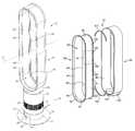
- FIG. 4is an exploded view of the nozzle of the fan of FIG. 1 ;
- FIG. 5is an enlarged view of area A indicated in FIG. 4 ;
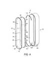
- FIG. 6is a front view of the nozzle of FIG. 4 ;
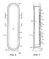
- FIG. 7is a sectional view of the nozzle taken along line E-E in FIG. 6 ;
- FIG. 8is a sectional view of the nozzle taken along line D-D in FIG. 6 ;
- FIG. 9is an enlarged view of a section of the nozzle illustrated in FIG. 8 ;
- FIG. 10is a sectional view of the nozzle taken along line C-C in FIG. 6 ;
- FIG. 11is an enlarged view of a section of the nozzle illustrated in FIG. 10 ;
- FIG. 12is a sectional view of the nozzle taken along line B-B in FIG. 6 ;
- FIG. 13is an enlarged view of a section of the nozzle illustrated in FIG. 12 ;
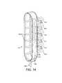
- FIG. 14illustrates the air flow through part of the nozzle of the fan of FIG. 1 .
- FIGS. 1 and 2illustrate an embodiment of a bladeless fan assembly.
- the bladeless fan assemblyis in the form of a domestic, portable tower fan 10 comprising a base 12 and an air outlet in the form of a nozzle 14 mounted on and supported by the base 12 .
- the base 12comprises a substantially cylindrical outer casing 16 mounted optionally on a disc-shaped base plate 18 .
- the outer casing 16comprises a plurality of air inlets 20 in the form of apertures formed in the outer casing 16 and through which a primary air flow is drawn into the base 12 from the external environment.
- the base 12further comprises a plurality of user-operable buttons 21 and a user-operable dial 22 for controlling the operation of the fan 10 .
- the base 12has a height in the range from 100 to 300 mm
- the outer casing 16has a diameter in the range from 100 to 200 mm.
- the nozzle 14has an elongate, annular shape and defines a central elongate opening 24 .
- the nozzle 14has a height in the range from 500 to 1000 mm, and a width in the range from 150 to 400 mm. In this example, the height of the nozzle is around 750 mm and the width of the nozzle is around 190 mm.
- the nozzle 14comprises a mouth 26 located towards the rear of the fan 10 for emitting air from the fan 10 and through the opening 24 .
- the mouth 26extends at least partially about the opening 24 .
- the inner periphery of the nozzle 14comprises a Coanda surface 28 located adjacent the mouth 26 and over which the mouth 26 directs the air emitted from the fan 10 , a diffuser surface 30 located downstream of the Coanda surface 28 and a guide surface 32 located downstream of the diffuser surface 30 .
- the diffuser surface 30is arranged to taper away from the central axis X of the opening 24 in such a way so as to assist the flow of air emitted from the fan 10 .
- the angle subtended between the diffuser surface 30 and the central axis X of the opening 24is in the range from 5 to 15°, and in this embodiment is around 7°.
- the guide surface 32is arranged at an angle to the diffuser surface 30 to further assist the efficient delivery of a cooling air flow from the fan 10 .
- the guide surface 32is arranged substantially parallel to the central axis X of the opening 24 to present a substantially flat and substantially smooth face to the air flow emitted from the mouth 26 .
- a visually appealing tapered surface 34is located downstream from the guide surface 32 , terminating at a tip surface 36 lying substantially perpendicular to the central axis X of the opening 24 .
- the angle subtended between the tapered surface 34 and the central axis X of the opening 24is preferably around 45°.
- the overall depth of the nozzle 24 in a direction extending along the central axis X of the opening 24is in the range from 100 to 150 mm, and in this example is around 110 mm.
- FIG. 3illustrates a sectional view through the base 12 of the fan 10 .
- the outer casing 16 of the base 12comprises a lower casing section 40 and a main casing section 42 mounted on the lower casing section 40 .
- the lower casing section 40houses a controller, indicated generally at 44 , for controlling the operation of the fan 10 in response to depression of the user operable buttons 21 shown in FIGS. 1 and 2 , and/or manipulation of the user, operable dial 22 .
- the lower casing section 40may optionally comprise a sensor 46 for receiving control signals from a remote control (not shown), and for conveying these control signals to the controller 44 . These control signals are preferably infrared signals.
- the sensor 46is located behind a window 47 through which the control signals enter the lower casing section 40 of the outer casing 16 of the base 12 .
- a light emitting diode(not shown) may be provided for indicating whether the fan 10 is in a stand-by mode.
- the lower casing section 40also houses a mechanism, indicated generally at 48 , for oscillating the main casing section 42 relative to the lower casing section 40 .
- the range of each oscillation cycle of the main casing section 42 relative to the lower casing section 40is preferably between 60° and 120°, and in this embodiment is around 90°.
- the oscillating mechanism 48is arranged to perform around 3 to 5 oscillation cycles per minute.
- a mains power cable 50extends through an aperture formed in the lower casing section 40 for supplying electrical power to the fan 10 .
- the main casing section 42comprises a cylindrical grille 60 in which an array of apertures 62 is formed to provide the air inlets 20 of the outer casing 16 of the base 12 .
- the main casing section 42houses an impeller 64 for drawing the primary air flow through the apertures 62 and into the base 12 .
- the impeller 64is in the form of a mixed flow impeller.
- the impeller 64is connected to a rotary shaft 66 extending outwardly from a motor 68 .
- the motor 68is a DC brushless motor having a speed which is variable by the controller 44 in response to user manipulation of the dial 22 and/or a signal received from the remote control.
- the maximum speed of the motor 68is preferably in the range from 5,000 to 10,000 rpm.
- the motor 68is housed within a motor bucket comprising an upper portion 70 connected to a lower portion 72 .
- the upper portion 70 of the motor bucketcomprises a diffuser 74 in the form of a stationary disc having spiral blades.
- the motor bucketis located within, and mounted on, a generally frustro-conical impeller housing 76 connected to the main casing section 42 .
- the impeller 42 and the impeller housing 76are shaped so that the impeller 42 is in close proximity to, but does not contact, the inner surface of the impeller housing 76 .
- a substantially annular inlet member 78is connected to the bottom of the impeller housing 76 for guiding the primary air flow into the impeller housing 76 .
- the impeller housing 76is oriented so that the primary air flow is exhausted from the impeller housing 76 in a substantially vertical direction.
- a profiled upper casing section 80is connected to the open upper end of the main casing section 42 of the base 12 , for example by means of snap-fit connections.
- An O-ring sealing membermay be used to form an air-tight seal between the main casing section 42 and the upper casing section 80 of the base 12 .
- the upper casing section 80comprises a chamber 86 for receiving the primary air flow from the main casing section 42 , and an aperture 88 through which the primary air flow passes from the base 12 into the nozzle 14 .
- the base 12further comprises silencing foam for reducing noise emissions from the base 12 .
- the main casing section 42 of the base 12comprises a first, generally cylindrical foam member 89 a located beneath the grille 60 , and a second, substantially annular foam member 89 b located between the impeller housing 76 and the inlet member 78 .
- the nozzle 14 of the fan 10will now be described with reference to FIGS. 4 to 13 .
- the nozzle 14comprises a casing comprising an elongate, annular outer casing section 90 connected to and extending about an elongate, annular inner casing section 92 .
- the inner casing section 92defines the central opening 24 of the nozzle 14 , and has an external peripheral surface 93 which is shaped to define the Coanda surface 28 , diffuser surface 30 , guide surface 32 and tapered surface 34 .
- the outer casing section 90 and the inner casing section 92together define an annular interior passage 94 of the nozzle 14 .
- the interior passage 94is located towards the front of the fan 10 .
- the interior passage 94extends about the opening 24 , and thus comprises two substantially vertically extending sections each adjacent a respective elongate side of the central opening 24 , an upper curved section joining the upper ends of the vertically extending sections, and a lower curved section joining the lower ends of the vertically extending sections.
- the interior passage 94is bounded by the internal peripheral surface 96 of the outer casing section 90 and the internal peripheral surface 98 of the inner casing section 92 .
- the outer casing section 90comprises a base 100 which is connected to, and over, the upper casing section 80 of the base 12 , for example by a snap-fit connection.
- the base 100 of the outer casing section 90comprises an aperture 102 which is aligned with the aperture 88 of the upper casing section 80 of the base 12 and through which the primary air flow enters the lower curved portion of the interior passage 94 of the nozzle 14 from the base 12 of the fan 10 .
- the mouth 26 of the nozzle 14is located towards the rear of the fan 10 .
- the mouth 26is defined by overlapping, or facing, portions 104 , 106 of the internal peripheral surface 96 of the outer casing section 90 and the external peripheral surface 93 of the inner casing section 92 , respectively.
- the mouth 26comprises two sections each extending along a respective elongate side of the central opening 24 of the nozzle 14 , and in fluid communication with a respective vertically extending section of the interior passage 94 of the nozzle 14 .
- the air flow through each section of the mouth 26is substantially orthogonal to the air flow through the respective vertically extending portion of the interior passage 94 of the nozzle 14 .
- Each section of the mouth 26is substantially U-shaped in cross-section, and so as a result the direction of the air flow is substantially reversed as the air flow passes through the mouth 26 .
- the overlapping portions 104 , 106 of the internal peripheral surface 96 of the outer casing section 90 and the external peripheral surface 93 of the inner casing section 92are shaped so that each section of the mouth 26 comprises a tapering portion 108 narrowing to an outlet 110 .
- Each outlet 110is in the form of a substantially vertically extending slot, preferably having a relatively constant width in the range from 0.5 to 5 mm. In this embodiment each outlet 110 has a width of around 1.1 mm.
- the mouth 26may thus be considered to comprise two outlets 110 each located on a respective side of the central opening 24 .
- the nozzle 14further comprises two curved seal members 112 , 114 each for forming a seal between the outer casing section 90 and the inner casing section 92 so that there is substantially no leakage of air from the curved sections of the interior passage 94 of the nozzle 14 .
- the nozzle 14comprises a plurality of stationary guide vanes 120 located within the interior passage 94 and each for directing a portion of the air flow towards the mouth 26 .
- the guide vanes 120are illustrated in FIGS. 4 , 5 , 7 , 10 and 11 .
- the guide vanes 120are preferably integral with the internal peripheral surface 98 of the inner casing section 92 of the nozzle 14 .
- the guide vanes 120are curved so that there is no significant loss in the velocity of the air flow as it is directed into the mouth 26 .
- the nozzle 14comprises two sets of guide vanes 120 , with each set of guide vanes 120 directing air passing along a respective vertically extending portion of the interior passage 94 towards its associated section of the mouth 26 .
- the guide vanes 120are substantially vertically aligned and evenly spaced apart to define a plurality of passageways 122 between the guide vanes 120 and through which air is directed into the mouth 26 .
- the even spacing of the guide vanes 120provides a substantially even distribution of the air stream along the length of the section of the mouth 26 .
- the guide vanes 120are preferably shaped so that a portion 124 of each guide vane 120 engages the internal peripheral surface 96 of the outer casing section 90 of the nozzle 24 so as to urge apart the overlapping portions 104 , 106 of the internal peripheral surface 96 of the outer casing section 90 and the external peripheral surface 93 of the inner casing section 92 . This can assist in maintaining the width of each outlet 110 at a substantially constant level along the length of each section of the mouth 26 .
- additional spacers 126are provided along the length of each section of the mouth 26 , also for urging apart the overlapping portions 104 , 106 of the internal peripheral surface 96 of the outer casing section 90 and the external peripheral surface 93 of the inner casing section 92 , to maintain the width of the outlet 110 at the desired level.
- Each spacer 126is located substantially midway between two adjacent guide vanes 120 .
- the spacers 126are preferably integral with the external peripheral surface 98 of the inner casing section 92 of the nozzle 14 . Additional spacers 126 may be provided between adjacent guide vanes 120 if so desired.
- the controller 44activates the motor 68 to rotate the impeller 64 , which causes a primary air flow to be drawn into the base 12 of the fan 10 through the air inlets 20 .
- the primary air flowmay be up to 30 liters per second, more preferably up to 50 liters per second.
- the primary air flowpasses through the impeller housing 76 and the upper casing section 80 of the base 12 , and enters the base 100 of the outer casing section 90 of the nozzle 14 , from which the primary air flow enters the interior passage 94 of the nozzle 14 .
- the primary air flowis divided into two air streams, one of which is indicated at 150 in FIG. 14 , which pass in opposite directions around the central opening 24 of the nozzle 14 .
- Each air stream 150enters a respective one of the two vertically extending sections of the interior passage 94 of the nozzle 14 , and is conveyed in a substantially vertical direction up through each of these sections of the interior passage 94 .
- the set of guide vanes 120 located within each of these sections of the interior passage 94directs the air stream 150 towards the section of the mouth 26 located adjacent that vertically extending section of the interior passage 94 .
- Each of the guide vanes 120directs a respective portion 152 of the air stream 150 towards the section of the mouth 26 so that there is a substantially uniform distribution of the air stream 150 along the length of the section of the mouth 26 .
- the guide vanes 120are shaped so that each portion 152 of the air stream 150 enters the mouth 26 in a substantially horizontal direction.
- the flow direction of the portion of the air streamis substantially reversed, as indicated at 154 in FIG. 14 .
- the portion of the air streamis constricted as the section of the mouth 26 tapers towards the outlet 110 thereof, channeled around the spacer 126 and emitted through the outlet 110 , again in a substantially horizontal direction.
- the primary air flow emitted from the mouth 26is directed over the Coanda surface 28 of the nozzle 14 , causing a secondary air flow to be generated by the entrainment of air from the external environment, specifically from the region around the outlets 110 of the mouth 26 and from around the rear of the nozzle 14 .
- This secondary air flowpasses predominantly through the central opening 24 of the nozzle 14 , where it combines with the primary air flow to produce a total air flow 156 , or air current, projected forward from the nozzle 14 .
- the even distribution of the primary air flow along the mouth 26 of the nozzle 14ensures that the air flow passes evenly over the diffuser surface 30 .
- the diffuser surface 30causes the mean speed of the air flow to be reduced by moving the air flow through a region of controlled expansion.
- the relatively shallow angle of the diffuser surface 30 to the central axis X of the opening 24allows the expansion of the air flow to occur gradually.
- a harsh or rapid divergencewould otherwise cause the air flow to become disrupted, generating vortices in the expansion region.
- Such vorticescan lead to an increase in turbulence and associated noise in the air flow, which can be undesirable, particularly in a domestic product such as a fan.
- the air flow projected forwards beyond the diffuser surface 30can tend to continue to diverge.
- the presence of the guide surface 32 extending substantially parallel to the central axis X of the opening 30tends to focus the air flow towards the user or into a room.
- the mass flow rate of the air current projected forward from the fan 10may be up to 500 liters per second, and in the preferred embodiment is up to 700 liters per second, and the maximum speed of the air current may be in the range from 3 to 4 m/s.
- the base and the nozzle of the fanmay be of a different shape and/or shape.
- the outlet of the mouthmay be modified.
- the outlet of the mouthmay be widened or narrowed to a variety of spacings to maximise air flow.
- the air flow emitted from the mouthmay pass over a surface, such as Coanda surface, but alternatively the air flow may be emitted through the mouth and projected forward from the fan without passing over an adjacent surface.
- the Coanda effectmay be effected over a number of different surfaces, or a number of internal or external designs may be used in combination to achieve the flow and entrainment required.
- the diffuser surfacemay be comprised of a variety of diffuser lengths and structures.
- the guide surfacemay be a variety of lengths, and may be arranged at a number of different positions and orientations as required for different fan requirements and different types of fan performance. Additional features such as lighting or a clock or LCD display may be provided within the central opening defined by the nozzle.
Landscapes
- Engineering & Computer Science (AREA)
- Mechanical Engineering (AREA)
- General Engineering & Computer Science (AREA)
- Physics & Mathematics (AREA)
- Fluid Mechanics (AREA)
- Structures Of Non-Positive Displacement Pumps (AREA)
- Jet Pumps And Other Pumps (AREA)
- Power Steering Mechanism (AREA)
- Turbine Rotor Nozzle Sealing (AREA)
Abstract
Description
This application claims the priority of United Kingdom Application No. 0903680.7 filed 4 Mar. 2009, the entire contents of which are incorporated herein by reference.
The present invention relates to a fan assembly. In a preferred embodiment, the present invention relates to a domestic fan, such as a tower fan, for creating an air current in a room, office or other domestic environment.
A conventional domestic fan typically includes a set of blades or vanes mounted for rotation about an axis, and drive apparatus for rotating the set of blades to generate an air flow. The movement and circulation of the air flow creates a ‘wind chill’ or breeze and, as a result, the user experiences a cooling effect as heat is dissipated through convection and evaporation.
Such fans are available in a variety of sizes and shapes. For example, a ceiling fan can be at least 1 m in diameter, and is usually mounted in a suspended manner from the ceiling to provide a downward flow of air to cool a room. On the other hand, desk fans are often around 30 cm in diameter, and are usually free standing and portable. Floor-standing tower fans generally comprise an elongate, vertically extending casing around 1 m high and housing one or more sets of rotary blades for generating an air flow, usually in the range from 300 to 500 l/s. An oscillating mechanism may be employed to rotate the outlet from the tower fan so that the air flow is swept over a wide area of a room.
A disadvantage of this type of arrangement is that the air flow produced by the rotating blades of the fan is generally not uniform. This is due to variations across the blade surface or across the outward facing surface of the fan. The extent of these variations can vary from product to product and even from one individual fan machine to another. These variations result in the generation of an uneven or ‘choppy’ air flow which can be felt as a series of pulses of air and which can be uncomfortable for a user.
In a domestic environment it is desirable for appliances to be as small and compact as possible due to space restrictions. It is undesirable for parts of the appliance to project outwardly, or for a user to be able to touch any moving parts, such as the blades. Many fans tend to have safety features such as a cage or shroud around the blades to prevent injury from the moving parts of the fan, but such caged parts can be difficult to clean.
In a first aspect the present invention provides a bladeless fan assembly for creating an air current, the fan assembly comprising a device for creating an air flow and a nozzle comprising an interior passage for receiving the air flow, a mouth for emitting the air flow, and a plurality of stationary guide vanes located within the interior passage and each for directing a portion of the air flow towards the mouth, the nozzle defining an opening through which air from outside the fan assembly is drawn by the air flow emitted from the mouth.
With this fan assembly an air current can be generated and a cooling effect created without the use of a bladed fan. Advantageously, the use of guide vanes each for directing a portion of the air flow towards the mouth provides a substantially uniform distribution of the air flow through the mouth. By preventing a substantial part of the air flow from being emitted from a relatively small portion of the mouth, a relatively uniform air current can be generated and guided controllably towards a user or into a room, and with little loss in the velocity of the air flow. The air current created by the fan assembly has the benefit of being an air flow with low turbulence and with a more linear air flow profile than that provided by other prior art devices. This can improve the comfort of a user receiving the air flow.
In the following description of fan assemblies, and, in particular a fan of the preferred embodiment, the term ‘bladeless’ is used to describe a fan assembly in which air flow is emitted or projected forward from the fan assembly without the use of moving blades. By this definition a bladeless fan assembly can be considered to have an output area or emission zone absent moving blades from which the air flow is directed towards a user or into a room. The output area of the bladeless fan assembly may be supplied with a primary air flow generated by one of a variety of different sources, such as pumps, generators, motors or other fluid transfer devices, and which may include a rotating device such as a motor rotor and/or a bladed impeller for generating the air flow. The generated primary air flow can pass from the room space or other environment outside the fan assembly through the interior passage to the nozzle, and then back out to the room space through the mouth of the nozzle.
Hence, the description of a fan assembly as bladeless is not intended to extend to the description of the power source and components such as motors that are required for secondary fan functions. Examples of secondary fan functions can include lighting, adjustment and oscillation of the fan assembly.
The direction in which air is emitted from the mouth is preferably substantially at a right angle to the direction in which the air flow passes through at least part of the interior passage. In the preferred embodiment, the air flow passes through at least part of the interior passage in a substantially vertical direction, and the air is emitted from the mouth in a substantially horizontal direction. In view of this, the guide vanes are preferably shaped to change the direction of the air flow by around 90°. The guide vanes are preferably curved so that there is no significant loss in the velocity of the portions of the air flow as they are directed into the mouth. The interior passage is preferably located towards the front of the nozzle, whereas the mouth is preferably located towards the rear of the nozzle and arranged to direct air towards the front of the nozzle and through the opening. Consequently, in the preferred embodiment the mouth is shaped so as substantially to reverse the flow direction of each portion of the air flow as it passes from the interior passage to an outlet of the mouth. The mouth is preferably substantially U-shaped in cross-section, and preferably narrows towards the outlet thereof.
The shape of the nozzle is not constrained by the requirement to include space for a bladed fan. Preferably, the interior passage surrounds the opening. For example, the interior passage may extend about the opening by a distance in the range from 50 to 250 cm. In a preferred embodiment the nozzle is an elongate, annular nozzle which preferably has a height in the range from 500 to 1000 mm, and a width in the range from 100 to 300 mm. The nozzle is preferably shaped to receive the air flow at one end thereof and to divide the air flow into two air streams, preferably with each air stream flowing along a respective elongate side of the opening. In this case, the plurality of guide vanes preferably comprises two sets of guide vanes, with each set of guide vanes being arranged to direct a respective air stream towards the mouth. Within each set, the guide vanes are spaced apart to define a plurality of passageways therebetween and through which a respective portion of the air stream is directed towards the mouth. In the preferred embodiment, the guide vanes within each set are preferably substantially vertically aligned.
The nozzle preferably comprises an inner casing section and an outer casing section which define the interior passage, the mouth and the opening. Each casing section may comprise a plurality of components, but in the preferred embodiment each of these sections is formed from a single annular component. The guide vanes are preferably located on, more preferably integral with, an internal surface of the inner casing section of the nozzle. The outer casing section is preferably shaped so as to partially overlap the inner casing section to define at least one outlet of the mouth between overlapping portions of the external surface of the inner casing section and the internal surface of the outer casing section of the nozzle. Each outlet is preferably in the form of a slot, preferably having a width in the range from 0.5 to 5 mm. In the preferred embodiment, the mouth comprises a plurality of such outlets spaced about the opening. For example, one or more sealing members may be located within the mouth to define a plurality of spaced apart outlets. Preferably, the outlets are of substantially the same size. In the preferred embodiment in which the nozzle is in the form of an annular, elongate nozzle, each outlet is preferably located along a respective elongate side of the inner periphery of the nozzle.
The guide vanes preferably engage the internal surface of the outer casing section of the nozzle so as to urge apart the overlapping portions of the inner casing section and the outer casing section of the nozzle. This can enable a substantially uniform outlet width to be achieved about the opening. The uniformity of the outlet width results in a relatively smooth, substantially even output of air from the nozzle. Depending on the spacing between adjacent guide vanes, one or more additional spacers may be located between adjacent guide vanes, preferably also integral with the inner casing section of the nozzle, to maintain a regular spacing between the overlapping portions of the inner casing section and the outer casing section of the nozzle.
The nozzle may comprise a surface, preferably a Coanda surface, located adjacent the mouth and over which the mouth is arranged to direct the air flow emitted therefrom. In the preferred embodiment, the external surface of the inner casing section of the nozzle is shaped to define the Coanda surface. A Coanda surface is a known type of surface over which fluid flow exiting an output orifice close to the surface exhibits the Coanda effect. The fluid tends to flow over the surface closely, almost ‘clinging to’ or ‘hugging’ the surface. The Coanda effect is already a proven, well documented method of entrainment in which a primary air flow is directed over a Coanda surface. A description of the features of a Coanda surface, and the effect of fluid flow over a Coanda surface, can be found in articles such as Reba, Scientific American, Volume 214, June 1966 pages 84 to 92. Through use of a Coanda surface, an increased amount of air from outside the fan assembly is drawn through the opening by the air emitted from the mouth.
In the preferred embodiment an air flow is created through the nozzle of the fan assembly. In the following description this air flow will be referred to as primary air flow. The primary air flow is emitted from the mouth of the nozzle and preferably passes over a Coanda surface. The primary air flow entrains air surrounding the mouth of the nozzle, which acts as an air amplifier to supply both the primary air flow and the entrained air to the user. The entrained air will be referred to here as a secondary air flow. The secondary air flow is drawn from the room space, region or external environment surrounding the mouth of the nozzle and, by displacement, from other regions around the fan assembly, and passes predominantly through the opening defined by the nozzle. The primary air flow directed over the Coanda surface combined with the entrained secondary air flow equates to a total air flow emitted or projected forward from the opening defined by the nozzle. The total air flow is sufficient for the fan assembly to create an air current suitable for cooling. Preferably, the entrainment of air surrounding the mouth of the nozzle is such that the primary air flow is amplified by at least five times, more preferably by at least ten times, while a smooth overall output is maintained.
In the preferred fan assembly the device for creating an air flow through the nozzle comprises an impeller driven by a motor. This can provide a fan assembly with efficient air flow generation. The device for creating an air flow preferably comprises a DC brushless motor and a mixed flow impeller. This can avoid frictional losses and carbon debris from the brushes used in a traditional brushed motor. Reducing carbon debris and emissions is advantageous in a clean or pollutant sensitive environment such as a hospital or around those with allergies. While induction motors, which are generally used in bladed fans, also have no brushes, a DC brushless motor can provide a much wider range of operating speeds than an induction motor.
In a second aspect the present invention provides a fan assembly for creating an air current, the fan assembly comprising a device for creating an air flow and a nozzle comprising an interior passage for receiving the air flow, a mouth for emitting the air flow, a plurality of stationary guide vanes located within the interior passage and each for directing a portion of the air flow towards the mouth, and a Coanda surface located adjacent the mouth and over which the mouth is arranged to direct the air flow, the nozzle defining an opening through which air from outside the fan assembly is drawn by the air flow emitted from the mouth.
The fan assembly may be desk, table or floor standing, or wall or ceiling mountable. For example, the fan assembly may be a portable, floor standing tower fan for creating an air current for circulating air, for example in a room, office or other domestic environment.
In a third aspect the present invention provides a portable tower fan comprising a base housing a device for creating an air flow and a casing comprising an interior passage for receiving the air flow, a mouth for emitting the air flow, and a plurality of stationary guide vanes located within the interior passage and each for directing a portion of the air flow towards the mouth, the casing defining an opening through which air from outside the fan assembly is drawn by the air flow emitted from the mouth.
In a fourth aspect the present invention provides a nozzle for a bladeless fan assembly for creating an air current, the nozzle comprising an interior passage for receiving an air flow, a mouth for emitting the air flow, and a plurality of stationary guide vanes located within the interior passage and each for directing a portion of the air flow towards the mouth, the nozzle defining an opening through which air from outside the fan assembly is drawn by the air flow emitted from the mouth.
Features described above in relation to any of the first to third aspects of the invention are equally applicable to the fourth aspect, and vice versa.
Preferably, the nozzle comprises a Coanda surface located adjacent the mouth and over which the mouth is arranged to direct the air flow. In a preferred embodiment the nozzle comprises a diffuser located downstream of the Coanda surface. The diffuser directs the air flow emitted towards a user's location while maintaining a smooth, even output, generating a suitable cooling effect without the user feeling a ‘choppy’ flow.
The invention also provides a fan assembly comprising a nozzle as aforementioned.
An embodiment of the present invention will now be described, by way of example only, with reference to the accompanying drawings, in which:
Thenozzle 14 has an elongate, annular shape and defines a centralelongate opening 24. Thenozzle 14 has a height in the range from 500 to 1000 mm, and a width in the range from 150 to 400 mm. In this example, the height of the nozzle is around 750 mm and the width of the nozzle is around 190 mm. Thenozzle 14 comprises amouth 26 located towards the rear of thefan 10 for emitting air from thefan 10 and through theopening 24. Themouth 26 extends at least partially about theopening 24. The inner periphery of thenozzle 14 comprises aCoanda surface 28 located adjacent themouth 26 and over which themouth 26 directs the air emitted from thefan 10, adiffuser surface 30 located downstream of theCoanda surface 28 and aguide surface 32 located downstream of thediffuser surface 30. Thediffuser surface 30 is arranged to taper away from the central axis X of theopening 24 in such a way so as to assist the flow of air emitted from thefan 10. The angle subtended between thediffuser surface 30 and the central axis X of theopening 24 is in the range from 5 to 15°, and in this embodiment is around 7°. Theguide surface 32 is arranged at an angle to thediffuser surface 30 to further assist the efficient delivery of a cooling air flow from thefan 10. In the illustrated embodiment theguide surface 32 is arranged substantially parallel to the central axis X of theopening 24 to present a substantially flat and substantially smooth face to the air flow emitted from themouth 26. A visually appealing taperedsurface 34 is located downstream from theguide surface 32, terminating at atip surface 36 lying substantially perpendicular to the central axis X of theopening 24. The angle subtended between thetapered surface 34 and the central axis X of theopening 24 is preferably around 45°. The overall depth of thenozzle 24 in a direction extending along the central axis X of theopening 24 is in the range from 100 to 150 mm, and in this example is around 110 mm.
Themain casing section 42 comprises acylindrical grille 60 in which an array ofapertures 62 is formed to provide theair inlets 20 of theouter casing 16 of thebase 12. Themain casing section 42 houses animpeller 64 for drawing the primary air flow through theapertures 62 and into thebase 12. Preferably, theimpeller 64 is in the form of a mixed flow impeller. Theimpeller 64 is connected to arotary shaft 66 extending outwardly from amotor 68. In this embodiment, themotor 68 is a DC brushless motor having a speed which is variable by thecontroller 44 in response to user manipulation of thedial 22 and/or a signal received from the remote control. The maximum speed of themotor 68 is preferably in the range from 5,000 to 10,000 rpm. Themotor 68 is housed within a motor bucket comprising anupper portion 70 connected to alower portion 72. Theupper portion 70 of the motor bucket comprises adiffuser 74 in the form of a stationary disc having spiral blades. The motor bucket is located within, and mounted on, a generally frustro-conical impeller housing 76 connected to themain casing section 42. Theimpeller 42 and theimpeller housing 76 are shaped so that theimpeller 42 is in close proximity to, but does not contact, the inner surface of theimpeller housing 76. A substantiallyannular inlet member 78 is connected to the bottom of theimpeller housing 76 for guiding the primary air flow into theimpeller housing 76. Theimpeller housing 76 is oriented so that the primary air flow is exhausted from theimpeller housing 76 in a substantially vertical direction.
A profiledupper casing section 80 is connected to the open upper end of themain casing section 42 of thebase 12, for example by means of snap-fit connections. An O-ring sealing member may be used to form an air-tight seal between themain casing section 42 and theupper casing section 80 of thebase 12. Theupper casing section 80 comprises achamber 86 for receiving the primary air flow from themain casing section 42, and anaperture 88 through which the primary air flow passes from the base12 into thenozzle 14.
Preferably, the base12 further comprises silencing foam for reducing noise emissions from thebase 12. In this embodiment, themain casing section 42 of thebase 12 comprises a first, generallycylindrical foam member 89alocated beneath thegrille 60, and a second, substantiallyannular foam member 89blocated between theimpeller housing 76 and theinlet member 78.
Thenozzle 14 of thefan 10 will now be described with reference toFIGS. 4 to 13 . Thenozzle 14 comprises a casing comprising an elongate, annularouter casing section 90 connected to and extending about an elongate, annularinner casing section 92. Theinner casing section 92 defines thecentral opening 24 of thenozzle 14, and has an externalperipheral surface 93 which is shaped to define theCoanda surface 28,diffuser surface 30,guide surface 32 and taperedsurface 34.
Theouter casing section 90 and theinner casing section 92 together define an annularinterior passage 94 of thenozzle 14. Theinterior passage 94 is located towards the front of thefan 10. Theinterior passage 94 extends about theopening 24, and thus comprises two substantially vertically extending sections each adjacent a respective elongate side of thecentral opening 24, an upper curved section joining the upper ends of the vertically extending sections, and a lower curved section joining the lower ends of the vertically extending sections. Theinterior passage 94 is bounded by the internalperipheral surface 96 of theouter casing section 90 and the internalperipheral surface 98 of theinner casing section 92. Theouter casing section 90 comprises a base100 which is connected to, and over, theupper casing section 80 of thebase 12, for example by a snap-fit connection. Thebase 100 of theouter casing section 90 comprises anaperture 102 which is aligned with theaperture 88 of theupper casing section 80 of thebase 12 and through which the primary air flow enters the lower curved portion of theinterior passage 94 of thenozzle 14 from thebase 12 of thefan 10.
With particular reference toFIGS. 8 and 9 , themouth 26 of thenozzle 14 is located towards the rear of thefan 10. Themouth 26 is defined by overlapping, or facing,portions peripheral surface 96 of theouter casing section 90 and the externalperipheral surface 93 of theinner casing section 92, respectively. In this embodiment, themouth 26 comprises two sections each extending along a respective elongate side of thecentral opening 24 of thenozzle 14, and in fluid communication with a respective vertically extending section of theinterior passage 94 of thenozzle 14. The air flow through each section of themouth 26 is substantially orthogonal to the air flow through the respective vertically extending portion of theinterior passage 94 of thenozzle 14. Each section of themouth 26 is substantially U-shaped in cross-section, and so as a result the direction of the air flow is substantially reversed as the air flow passes through themouth 26. In this embodiment, the overlappingportions peripheral surface 96 of theouter casing section 90 and the externalperipheral surface 93 of theinner casing section 92 are shaped so that each section of themouth 26 comprises a taperingportion 108 narrowing to anoutlet 110. Eachoutlet 110 is in the form of a substantially vertically extending slot, preferably having a relatively constant width in the range from 0.5 to 5 mm. In this embodiment eachoutlet 110 has a width of around 1.1 mm.
Themouth 26 may thus be considered to comprise twooutlets 110 each located on a respective side of thecentral opening 24. Returning toFIG. 4 , thenozzle 14 further comprises twocurved seal members outer casing section 90 and theinner casing section 92 so that there is substantially no leakage of air from the curved sections of theinterior passage 94 of thenozzle 14.
In order to direct the primary air flow into themouth 26, thenozzle 14 comprises a plurality ofstationary guide vanes 120 located within theinterior passage 94 and each for directing a portion of the air flow towards themouth 26. The guide vanes120 are illustrated inFIGS. 4 ,5,7,10 and11. The guide vanes120 are preferably integral with the internalperipheral surface 98 of theinner casing section 92 of thenozzle 14. The guide vanes120 are curved so that there is no significant loss in the velocity of the air flow as it is directed into themouth 26. In this embodiment thenozzle 14 comprises two sets ofguide vanes 120, with each set ofguide vanes 120 directing air passing along a respective vertically extending portion of theinterior passage 94 towards its associated section of themouth 26. Within each set, theguide vanes 120 are substantially vertically aligned and evenly spaced apart to define a plurality ofpassageways 122 between theguide vanes 120 and through which air is directed into themouth 26. The even spacing of theguide vanes 120 provides a substantially even distribution of the air stream along the length of the section of themouth 26.
With reference toFIG. 11 , theguide vanes 120 are preferably shaped so that aportion 124 of eachguide vane 120 engages the internalperipheral surface 96 of theouter casing section 90 of thenozzle 24 so as to urge apart the overlappingportions peripheral surface 96 of theouter casing section 90 and the externalperipheral surface 93 of theinner casing section 92. This can assist in maintaining the width of eachoutlet 110 at a substantially constant level along the length of each section of themouth 26. With reference toFIGS. 7 ,12 and13, in this embodimentadditional spacers 126 are provided along the length of each section of themouth 26, also for urging apart the overlappingportions peripheral surface 96 of theouter casing section 90 and the externalperipheral surface 93 of theinner casing section 92, to maintain the width of theoutlet 110 at the desired level. Eachspacer 126 is located substantially midway between two adjacent guide vanes120. To facilitate manufacture thespacers 126 are preferably integral with the externalperipheral surface 98 of theinner casing section 92 of thenozzle 14.Additional spacers 126 may be provided betweenadjacent guide vanes 120 if so desired.
In use, when the user depresses an appropriate one of thebuttons 21 on thebase 12 of thefan 10 thecontroller 44 activates themotor 68 to rotate theimpeller 64, which causes a primary air flow to be drawn into thebase 12 of thefan 10 through theair inlets 20. The primary air flow may be up to 30 liters per second, more preferably up to 50 liters per second. The primary air flow passes through theimpeller housing 76 and theupper casing section 80 of thebase 12, and enters thebase 100 of theouter casing section 90 of thenozzle 14, from which the primary air flow enters theinterior passage 94 of thenozzle 14.
With reference also toFIG. 14 the primary air flow, indicated at148, is divided into two air streams, one of which is indicated at150 inFIG. 14 , which pass in opposite directions around thecentral opening 24 of thenozzle 14. Eachair stream 150 enters a respective one of the two vertically extending sections of theinterior passage 94 of thenozzle 14, and is conveyed in a substantially vertical direction up through each of these sections of theinterior passage 94. The set ofguide vanes 120 located within each of these sections of theinterior passage 94 directs theair stream 150 towards the section of themouth 26 located adjacent that vertically extending section of theinterior passage 94. Each of theguide vanes 120 directs arespective portion 152 of theair stream 150 towards the section of themouth 26 so that there is a substantially uniform distribution of theair stream 150 along the length of the section of themouth 26. The guide vanes120 are shaped so that eachportion 152 of theair stream 150 enters themouth 26 in a substantially horizontal direction. Within each section of themouth 26, the flow direction of the portion of the air stream is substantially reversed, as indicated at154 inFIG. 14 . The portion of the air stream is constricted as the section of themouth 26 tapers towards theoutlet 110 thereof, channeled around thespacer 126 and emitted through theoutlet 110, again in a substantially horizontal direction.
The primary air flow emitted from themouth 26 is directed over theCoanda surface 28 of thenozzle 14, causing a secondary air flow to be generated by the entrainment of air from the external environment, specifically from the region around theoutlets 110 of themouth 26 and from around the rear of thenozzle 14. This secondary air flow passes predominantly through thecentral opening 24 of thenozzle 14, where it combines with the primary air flow to produce atotal air flow 156, or air current, projected forward from thenozzle 14.
The even distribution of the primary air flow along themouth 26 of thenozzle 14 ensures that the air flow passes evenly over thediffuser surface 30. Thediffuser surface 30 causes the mean speed of the air flow to be reduced by moving the air flow through a region of controlled expansion. The relatively shallow angle of thediffuser surface 30 to the central axis X of theopening 24 allows the expansion of the air flow to occur gradually. A harsh or rapid divergence would otherwise cause the air flow to become disrupted, generating vortices in the expansion region. Such vortices can lead to an increase in turbulence and associated noise in the air flow, which can be undesirable, particularly in a domestic product such as a fan. In the absence of theguide vanes 120 most of the primary air flow would tend to leave thefan 10 through the upper part of themouth 26, and to leave themouth 26 upwardly at an acute angle to the central axis of theopening 24. As a result there would be an uneven distribution of air within the air current generated by thefan 10. Furthermore, most of the air flow from thefan 10 would not be properly diffused by thediffuser surface 30, leading to the generation of an air current with much greater turbulence.
The air flow projected forwards beyond thediffuser surface 30 can tend to continue to diverge. The presence of theguide surface 32 extending substantially parallel to the central axis X of theopening 30 tends to focus the air flow towards the user or into a room.
Depending on the speed of themotor 64, the mass flow rate of the air current projected forward from thefan 10 may be up to 500 liters per second, and in the preferred embodiment is up to 700 liters per second, and the maximum speed of the air current may be in the range from 3 to 4 m/s.
The invention is not limited to the detailed description given above. Variations will be apparent to the person skilled in the art.
For example, the base and the nozzle of the fan may be of a different shape and/or shape. The outlet of the mouth may be modified. For example, the outlet of the mouth may be widened or narrowed to a variety of spacings to maximise air flow. The air flow emitted from the mouth may pass over a surface, such as Coanda surface, but alternatively the air flow may be emitted through the mouth and projected forward from the fan without passing over an adjacent surface. The Coanda effect may be effected over a number of different surfaces, or a number of internal or external designs may be used in combination to achieve the flow and entrainment required. The diffuser surface may be comprised of a variety of diffuser lengths and structures. The guide surface may be a variety of lengths, and may be arranged at a number of different positions and orientations as required for different fan requirements and different types of fan performance. Additional features such as lighting or a clock or LCD display may be provided within the central opening defined by the nozzle.
Claims (27)
1. A bladeless fan assembly for creating an air current, the fan assembly comprising a device for creating an air flow and a nozzle comprising an interior passage for receiving the air flow, a mouth for emitting the air flow, and a plurality of stationary guide vanes located within the interior passage and each shaped to change a direction of the air flow by around 90° for directing a portion of the air flow towards the mouth, wherein the mouth is shaped so as substantially to reverse a flow direction of each portion of the air flow, the nozzle defining an opening through which air from outside the fan assembly is drawn by the air flow emitted from the mouth, wherein the nozzle comprises an inner casing section and an outer casing section which together define the interior passage and the mouth, wherein the guide vanes protrude from an internal surface of the nozzle, wherein the mouth comprises an outlet located between an external surface of the inner casing section of the nozzle and an internal surface of the outer casing section of the nozzle, and wherein the mouth comprises a plurality of said outlets spaced about the opening.
2. The fan assembly ofclaim 1 , wherein the interior passage is shaped to divide the received air flow into two air streams, and wherein the plurality of guide vanes comprises two sets of guide vanes each arranged to direct a respective air stream towards the mouth.
3. The fan assembly ofclaim 2 , wherein the interior passage is shaped to convey each air stream along a respective side of the opening.
4. The fan assembly ofclaim 1 , wherein each of the plurality of outlets is in the form of a slot.
5. The fan assembly ofclaim 1 , wherein each of the plurality of outlets has a width in the range from 0.5 to 5 mm.
6. The fan assembly ofclaim 1 , wherein the outlets are of substantially the same size.
7. The fan assembly ofclaim 1 , wherein the guide vanes engage the internal surface of the outer casing section of the nozzle.
8. The fan assembly ofclaim 1 , wherein the nozzle extends about the opening by a distance in the range from 50 to 250 cm.
9. The fan assembly ofclaim 1 , wherein the nozzle comprises an elongate, annular nozzle.
10. The fan assembly ofclaim 1 , wherein the device for creating the air flow through the nozzle comprises an impeller driven by a motor.
11. The fan assembly ofclaim 10 , wherein the motor is a DC brushless motor, and the impeller is a mixed flow impeller.
12. The fan assembly ofclaim 1 , in the form of a portable tower fan.
13. The fan assembly ofclaim 1 , wherein the guide vanes protrude from an internal surface of the inner casing section of the nozzle.
14. A nozzle for a bladeless fan assembly for creating an air current, the nozzle comprising an interior passage for receiving an air flow, a mouth for emitting the air flow, an inner casing section and an outer casing section which together define the interior passage and the mouth, and a plurality of stationary guide vanes located within the interior passage and each shaped to change a direction of the air flow by around 90° for directing a portion of the air flow towards the mouth, wherein the mouth is shaped so as substantially to reverse a flow direction of each portion of the air flow, the nozzle defining an opening through which air from outside the fan assembly is drawn by the air flow emitted from the mouth, wherein the guide vanes protrude from an internal surface of the nozzle, wherein the mouth comprises an outlet located between an external surface of the inner casing section of the nozzle and an internal surface of the outer casing section of the nozzle, and wherein the mouth comprises a plurality of said outlets spaced about the opening.
15. The nozzle ofclaim 14 , wherein the interior passage is shaped to divide the received air flow into two air streams, and wherein the plurality of guide vanes comprises two sets of guide vanes each arranged to direct a respective air stream towards the mouth.
16. The nozzle ofclaim 15 , wherein the interior passage is shaped to convey each air stream along a respective side of the opening.
17. The nozzle ofclaim 14 , wherein each of the plurality of outlets is in the form of a slot.
18. The nozzle ofclaim 14 , wherein each of the plurality of outlets has a width in the range from 0.5 to 5 mm.
19. The nozzle ofclaim 14 , wherein the outlets are of substantially the same size.
20. The nozzle ofclaim 14 , wherein the guide vanes engage the internal surface of the outer casing section of the nozzle.
21. The nozzle ofclaim 14 , wherein the interior passage extends about the opening by a distance in the range from 50 to 250 cm.
22. The nozzle ofclaim 14 , in the form of an elongate, annular nozzle.
23. The nozzle ofclaim 14 , comprising a surface located adjacent the mouth and over which the mouth is arranged to direct the air flow.
24. The nozzle ofclaim 23 , wherein the surface is a Coanda surface.
25. The nozzle ofclaim 23 , comprising a diffuser located downstream of the Coanda surface.
26. A fan assembly comprising the nozzle as claimed inclaim 14 .
27. The nozzle ofclaim 14 , wherein the guide vanes protrude from an internal surface of the inner casing section of the nozzle.
Applications Claiming Priority (2)
| Application Number | Priority Date | Filing Date | Title |
|---|---|---|---|
| GB0903680.7 | 2009-03-04 | ||
| GB0903680AGB2468323A (en) | 2009-03-04 | 2009-03-04 | Fan assembly |
Publications (2)
| Publication Number | Publication Date |
|---|---|
| US20100226769A1 US20100226769A1 (en) | 2010-09-09 |
| US8613601B2true US8613601B2 (en) | 2013-12-24 |
Family
ID=40580577
Family Applications (1)
| Application Number | Title | Priority Date | Filing Date |
|---|---|---|---|
| US12/716,694Active2032-06-25US8613601B2 (en) | 2009-03-04 | 2010-03-03 | Fan assembly |
Country Status (23)
| Country | Link |
|---|---|
| US (1) | US8613601B2 (en) |
| EP (1) | EP2271845B1 (en) |
| JP (1) | JP5068839B2 (en) |
| KR (1) | KR101331485B1 (en) |
| CN (1) | CN101825098B (en) |
| AT (1) | ATE512308T1 (en) |
| AU (2) | AU2010219491B2 (en) |
| BR (1) | BRPI1006029A2 (en) |
| CA (1) | CA2746547C (en) |
| CY (1) | CY1111818T1 (en) |
| DK (1) | DK2271845T3 (en) |
| ES (1) | ES2366277T3 (en) |
| GB (1) | GB2468323A (en) |
| HR (1) | HRP20110596T1 (en) |
| IL (1) | IL214535A (en) |
| MY (1) | MY156844A (en) |
| NZ (1) | NZ593355A (en) |
| PL (1) | PL2271845T3 (en) |
| PT (1) | PT2271845E (en) |
| RU (1) | RU2505714C2 (en) |
| SG (1) | SG172129A1 (en) |
| WO (1) | WO2010100456A1 (en) |
| ZA (1) | ZA201107219B (en) |
Cited By (13)
| Publication number | Priority date | Publication date | Assignee | Title |
|---|---|---|---|---|
| US20130202413A1 (en)* | 2012-02-06 | 2013-08-08 | Dyson Technology Limited | Fan |
| US20130202412A1 (en)* | 2012-02-06 | 2013-08-08 | Dyson Technology Limited | Fan |
| US20130199372A1 (en)* | 2012-02-06 | 2013-08-08 | Dyson Technology Limited | Fan assembly |
| US9486562B2 (en) | 2014-10-24 | 2016-11-08 | Integrated Surgical, Llc | Suction device for surgical instruments |
| USD774239S1 (en)* | 2015-04-30 | 2016-12-13 | Pablo, Inc. | Lighting fixture |
| USD776327S1 (en)* | 2015-11-05 | 2017-01-10 | Koncept Technologies, Inc. | Lamp |
| USD868328S1 (en)* | 2017-10-12 | 2019-11-26 | Herman Chang | LED lamp fan |
| US10821212B2 (en) | 2015-07-13 | 2020-11-03 | Conmed Corporation | Surgical suction device that uses positive pressure gas |
| US10926007B2 (en) | 2015-07-13 | 2021-02-23 | Conmed Corporation | Surgical suction device that uses positive pressure gas |
| US11384956B2 (en) | 2017-05-22 | 2022-07-12 | Sharkninja Operating Llc | Modular fan assembly with articulating nozzle |
| US11480193B2 (en) | 2017-10-20 | 2022-10-25 | Techtronic Power Tools Technology Limited | Fan |
| US20240377103A1 (en)* | 2023-05-12 | 2024-11-14 | Mitchell J. Francis | Portable electric heater |
| USD1057918S1 (en) | 2021-06-23 | 2025-01-14 | Sharkninja Operating Llc | Air purifier |
Families Citing this family (132)
| Publication number | Priority date | Publication date | Assignee | Title |
|---|---|---|---|---|
| GB0814835D0 (en) | 2007-09-04 | 2008-09-17 | Dyson Technology Ltd | A Fan |
| GB2463698B (en) | 2008-09-23 | 2010-12-01 | Dyson Technology Ltd | A fan |
| GB2464736A (en) | 2008-10-25 | 2010-04-28 | Dyson Technology Ltd | Fan with a filter |
| GB2466058B (en)* | 2008-12-11 | 2010-12-22 | Dyson Technology Ltd | Fan nozzle with spacers |
| GB2468326A (en) | 2009-03-04 | 2010-09-08 | Dyson Technology Ltd | Telescopic pedestal fan |
| GB2468312A (en) | 2009-03-04 | 2010-09-08 | Dyson Technology Ltd | Fan assembly |
| GB0903682D0 (en) | 2009-03-04 | 2009-04-15 | Dyson Technology Ltd | A fan |
| GB2468322B (en) | 2009-03-04 | 2011-03-16 | Dyson Technology Ltd | Tilting fan stand |
| PL2276933T3 (en) | 2009-03-04 | 2011-10-31 | Dyson Technology Ltd | A fan |
| KR101395177B1 (en) | 2009-03-04 | 2014-05-15 | 다이슨 테크놀러지 리미티드 | A fan |
| NZ593318A (en) | 2009-03-04 | 2012-11-30 | Dyson Technology Ltd | An annular fan assembly with a silencing member |
| GB2468317A (en) | 2009-03-04 | 2010-09-08 | Dyson Technology Ltd | Height adjustable and oscillating fan |
| GB2468323A (en) | 2009-03-04 | 2010-09-08 | Dyson Technology Ltd | Fan assembly |
| GB2468315A (en) | 2009-03-04 | 2010-09-08 | Dyson Technology Ltd | Tilting fan |
| GB2468331B (en) | 2009-03-04 | 2011-02-16 | Dyson Technology Ltd | A fan |
| GB2468320C (en) | 2009-03-04 | 2011-06-01 | Dyson Technology Ltd | Tilting fan |
| CN202056982U (en) | 2009-03-04 | 2011-11-30 | 戴森技术有限公司 | Humidifying device |
| GB2468329A (en) | 2009-03-04 | 2010-09-08 | Dyson Technology Ltd | Fan assembly |
| GB0919473D0 (en) | 2009-11-06 | 2009-12-23 | Dyson Technology Ltd | A fan |
| GB2478925A (en) | 2010-03-23 | 2011-09-28 | Dyson Technology Ltd | External filter for a fan |
| GB2478927B (en) | 2010-03-23 | 2016-09-14 | Dyson Technology Ltd | Portable fan with filter unit |
| SG186071A1 (en) | 2010-05-27 | 2013-01-30 | Dyson Technology Ltd | Device for blowing air by means of narrow slit nozzle assembly |
| GB2482548A (en) | 2010-08-06 | 2012-02-08 | Dyson Technology Ltd | A fan assembly with a heater |
| GB2482547A (en) | 2010-08-06 | 2012-02-08 | Dyson Technology Ltd | A fan assembly with a heater |
| GB2482549A (en) | 2010-08-06 | 2012-02-08 | Dyson Technology Ltd | A fan assembly with a heater |
| GB2483448B (en) | 2010-09-07 | 2015-12-02 | Dyson Technology Ltd | A fan |
| JP5588565B2 (en) | 2010-10-13 | 2014-09-10 | ダイソン テクノロジー リミテッド | Blower assembly |
| GB2484670B (en) | 2010-10-18 | 2018-04-25 | Dyson Technology Ltd | A fan assembly |
| EP2630373B1 (en) | 2010-10-18 | 2016-12-28 | Dyson Technology Limited | A fan assembly |
| JP5778293B2 (en) | 2010-11-02 | 2015-09-16 | ダイソン テクノロジー リミテッド | Blower assembly |
| US8573115B2 (en)* | 2010-11-15 | 2013-11-05 | Conair Corporation | Brewed beverage appliance and method |
| CN101985948A (en)* | 2010-11-27 | 2011-03-16 | 任文华 | Bladeless fan |
| GB2486019B (en) | 2010-12-02 | 2013-02-20 | Dyson Technology Ltd | A fan |
| JP5923686B2 (en)* | 2011-07-13 | 2016-05-25 | パナソニックIpマネジメント株式会社 | Cool air machine |
| GB2493506B (en) | 2011-07-27 | 2013-09-11 | Dyson Technology Ltd | A fan assembly |
| BR112014001474A2 (en) | 2011-07-27 | 2017-02-21 | Dyson Technology Ltd | fan assembly |
| GB201119500D0 (en) | 2011-11-11 | 2011-12-21 | Dyson Technology Ltd | A fan assembly |
| KR101277645B1 (en)* | 2011-11-14 | 2013-06-21 | 인하대학교 산학협력단 | Hybrid Electric Power Generation System Using Photovoltaics and Wind Power |
| CN102628454B (en)* | 2011-11-15 | 2014-02-19 | 杭州金鱼电器集团有限公司 | Air duct system of vertical type fan-blade-free electric fan |
| GB2496877B (en) | 2011-11-24 | 2014-05-07 | Dyson Technology Ltd | A fan assembly |
| GB2498547B (en) | 2012-01-19 | 2015-02-18 | Dyson Technology Ltd | A fan |
| GB2512192B (en) | 2012-03-06 | 2015-08-05 | Dyson Technology Ltd | A Humidifying Apparatus |
| GB2500010B (en) | 2012-03-06 | 2016-08-24 | Dyson Technology Ltd | A humidifying apparatus |
| GB2500012B (en) | 2012-03-06 | 2016-07-06 | Dyson Technology Ltd | A Humidifying Apparatus |
| RU2606194C2 (en) | 2012-03-06 | 2017-01-10 | Дайсон Текнолоджи Лимитед | Fan unit |
| GB2500017B (en) | 2012-03-06 | 2015-07-29 | Dyson Technology Ltd | A Humidifying Apparatus |
| GB2500011B (en) | 2012-03-06 | 2016-07-06 | Dyson Technology Ltd | A Humidifying Apparatus |
| GB2500903B (en) | 2012-04-04 | 2015-06-24 | Dyson Technology Ltd | Heating apparatus |
| CN103362875A (en)* | 2012-04-07 | 2013-10-23 | 任文华 | Fan and jet nozzle thereof |
| CN102661294B (en)* | 2012-04-10 | 2014-10-29 | 宁波宏钜电器科技有限公司 | Bladeless fan |
| GB2501301B (en) | 2012-04-19 | 2016-02-03 | Dyson Technology Ltd | A fan assembly |
| CN103375445A (en)* | 2012-04-28 | 2013-10-30 | 任文华 | Fan and rack for fan |
| JP6141412B2 (en)* | 2012-05-02 | 2017-06-07 | ウー ハ,スン | Fan |
| GB2532557B (en) | 2012-05-16 | 2017-01-11 | Dyson Technology Ltd | A fan comprsing means for suppressing noise |
| GB2518935B (en) | 2012-05-16 | 2016-01-27 | Dyson Technology Ltd | A fan |
| EP2850324A2 (en) | 2012-05-16 | 2015-03-25 | Dyson Technology Limited | A fan |
| CN103470543B (en)* | 2012-06-06 | 2015-10-21 | 江西维特科技有限公司 | A kind of without blade fan |
| CN102840161B (en)* | 2012-06-28 | 2015-01-21 | 胡晓存 | Blade-free fan component |
| GB2503907B (en) | 2012-07-11 | 2014-05-28 | Dyson Technology Ltd | A fan assembly |
| CN103629165A (en)* | 2012-08-21 | 2014-03-12 | 任文华 | Bladeless fan and nozzle for bladeless fan |
| CN102829003B (en)* | 2012-09-10 | 2015-06-03 | 淮南矿业(集团)有限责任公司 | Pneumatic bladeless fan for mine |
| DE102012216778A1 (en) | 2012-09-19 | 2014-05-28 | Bayerische Motoren Werke Aktiengesellschaft | Vehicle-pressure tank for receiving fluid i.e. hydrogen, under normal temperature or in sub-zero state, has valve device controlled under conditions by vehicle user such that minimum pressure is reached, so that removal of fluid is allowed |
| CN103016422A (en)* | 2012-10-06 | 2013-04-03 | 任文华 | Fan |
| BR302013003358S1 (en) | 2013-01-18 | 2014-11-25 | Dyson Technology Ltd | CONFIGURATION APPLIED ON HUMIDIFIER |
| AU350179S (en) | 2013-01-18 | 2013-08-15 | Dyson Technology Ltd | Humidifier or fan |
| AU350140S (en) | 2013-01-18 | 2013-08-13 | Dyson Technology Ltd | Humidifier or fan |
| AU350181S (en) | 2013-01-18 | 2013-08-15 | Dyson Technology Ltd | Humidifier or fan |
| SG11201505665RA (en) | 2013-01-29 | 2015-08-28 | Dyson Technology Ltd | A fan assembly |
| GB2510195B (en) | 2013-01-29 | 2016-04-27 | Dyson Technology Ltd | A fan assembly |
| CA152656S (en) | 2013-03-07 | 2014-05-20 | Dyson Technology Ltd | Fan |
| BR302013004394S1 (en) | 2013-03-07 | 2014-12-02 | Dyson Technology Ltd | CONFIGURATION APPLIED TO FAN |
| CA152658S (en) | 2013-03-07 | 2014-05-20 | Dyson Technology Ltd | Fan |
| USD729372S1 (en) | 2013-03-07 | 2015-05-12 | Dyson Technology Limited | Fan |
| CA152657S (en) | 2013-03-07 | 2014-05-20 | Dyson Technology Ltd | Fan |
| CA152655S (en) | 2013-03-07 | 2014-05-20 | Dyson Technology Ltd | Fan |
| GB2536767B (en)* | 2013-03-11 | 2017-11-15 | Dyson Technology Ltd | A fan assembly nozzle with control port |
| GB2516058B (en) | 2013-07-09 | 2016-12-21 | Dyson Technology Ltd | A fan assembly with an oscillation and tilt mechanism |
| CA154722S (en) | 2013-08-01 | 2015-02-16 | Dyson Technology Ltd | Fan |
| TWD172707S (en) | 2013-08-01 | 2015-12-21 | 戴森科技有限公司 | A fan |
| CA154723S (en) | 2013-08-01 | 2015-02-16 | Dyson Technology Ltd | Fan |
| GB2518638B (en) | 2013-09-26 | 2016-10-12 | Dyson Technology Ltd | Humidifying apparatus |
| KR101472758B1 (en)* | 2014-02-07 | 2014-12-15 | 이광식 | Spacer for nozzle |
| JP6428004B2 (en) | 2014-07-10 | 2018-11-28 | 株式会社デンソー | Blower |
| GB2528708B (en) | 2014-07-29 | 2016-06-29 | Dyson Technology Ltd | A fan assembly |
| GB2528704A (en) | 2014-07-29 | 2016-02-03 | Dyson Technology Ltd | Humidifying apparatus |
| GB2528709B (en) | 2014-07-29 | 2017-02-08 | Dyson Technology Ltd | Humidifying apparatus |
| TWD179707S (en)* | 2015-01-30 | 2016-11-21 | 戴森科技有限公司 | A fan |
| TWD173932S (en)* | 2015-01-30 | 2016-02-21 | 戴森科技有限公司 | A fan |
| TWD173930S (en)* | 2015-01-30 | 2016-02-21 | 戴森科技有限公司 | A fan |
| TWD173931S (en)* | 2015-01-30 | 2016-02-21 | 戴森科技有限公司 | A fan |
| TWD173928S (en)* | 2015-01-30 | 2016-02-21 | 戴森科技有限公司 | A fan |
| TWD173929S (en)* | 2015-01-30 | 2016-02-21 | 戴森科技有限公司 | A fan |
| DE202015101896U1 (en) | 2015-03-25 | 2015-05-06 | Ford Global Technologies, Llc | Radiator fan assembly for a cooling system of a liquid-cooled engine of a vehicle |
| DE102015205414B3 (en)* | 2015-03-25 | 2016-05-25 | Ford Global Technologies, Llc | Radiator fan assembly adapted for a cooling system of a liquid-cooled engine of a vehicle |
| DE102015205415A1 (en) | 2015-03-25 | 2016-09-29 | Ford Global Technologies, Llc | Radiator fan assembly for a cooling system of a liquid-cooled engine of a vehicle |
| JP6515328B2 (en)* | 2015-03-26 | 2019-05-22 | パナソニックIpマネジメント株式会社 | Air blower |
| USD804007S1 (en)* | 2015-11-25 | 2017-11-28 | Vornado Air Llc | Air circulator |
| CN106015046B (en)* | 2016-06-24 | 2019-11-12 | 珠海格力电器股份有限公司 | Tower fan structure |
| CN106246602B (en)* | 2016-09-30 | 2021-09-21 | 广东美的环境电器制造有限公司 | Machine head for bladeless fan and bladeless fan |
| CN106246601B (en)* | 2016-09-30 | 2020-06-26 | 广东美的环境电器制造有限公司 | Handpieces and Bladeless Fans for Bladeless Fans |
| WO2018059041A1 (en)* | 2016-09-30 | 2018-04-05 | 广东美的环境电器制造有限公司 | Head for bladeless fan and bladeless fan |
| FR3065749B1 (en)* | 2017-04-28 | 2019-05-03 | Valeo Systemes Thermiques | TUBE VENTILATION DEVICE PROVIDED WITH AIR FLOW GUIDING MEANS FOR A MOTOR VEHICLE HEAT EXCHANGE MODULE |
| FR3065750B1 (en)* | 2017-04-28 | 2019-04-19 | Valeo Systemes Thermiques | CONDUIT VENTILATION DEVICE PROVIDED WITH ASYMMETRIC AIR FLOW DISTRIBUTION MEANS FOR A MOTOR VEHICLE HEAT EXCHANGE MODULE |
| FR3065989B1 (en)* | 2017-04-28 | 2021-01-01 | Valeo Systemes Thermiques | COANDA-EFFECT TUBE VENTILATION DEVICE WITH EJECTION SLOT SIZING OPTIMIZED FOR MOTOR VEHICLE HEAT EXCHANGE MODULE |
| WO2018197818A1 (en)* | 2017-04-28 | 2018-11-01 | Valeo Systemes Thermiques | Ventilation device with tubes provided with air flow guide means for a motor vehicle heat exchange module |
| FR3065753B1 (en)* | 2017-04-28 | 2021-01-01 | Valeo Systemes Thermiques | COANDA-EFFECT TUBE VENTILATION DEVICE WITH OPTIMIZED SIZING FOR MOTOR VEHICLE HEAT EXCHANGE MODULE |
| FR3065751B1 (en)* | 2017-04-28 | 2020-12-04 | Valeo Systemes Thermiques | MANUFACTURING PROCESS OF A VENTILATION DEVICE WITH COANDA-EFFECT TUBES FOR A MOTOR VEHICLE HEAT EXCHANGE MODULE |
| FR3065748B1 (en)* | 2017-04-28 | 2021-01-01 | Valeo Systemes Thermiques | COANDA-EFFECT TUBE VENTILATION DEVICE FOR MOTOR VEHICLE HEAT EXCHANGE MODULE |
| FR3065752B1 (en)* | 2017-04-28 | 2021-01-01 | Valeo Systemes Thermiques | COANDA-EFFECT TUBE VENTILATION DEVICE WITH DOUBLE EJECTORS FOR MOTOR VEHICLE HEAT EXCHANGE MODULE |
| FR3065988B1 (en)* | 2017-04-28 | 2021-01-01 | Valeo Systemes Thermiques | COANDA-EFFECT TUBE VENTILATION DEVICE WITH DOUBLE EJECTORS WITH OPTIMIZED DIMENSIONING FOR MOTOR VEHICLE HEAT EXCHANGE MODULE |
| FR3067401B1 (en)* | 2017-06-12 | 2021-03-05 | Valeo Systemes Thermiques | MOTOR VEHICLE VENTILATION SYSTEM |
| FR3073563B1 (en)* | 2017-09-29 | 2019-11-22 | Valeo Systemes Thermiques | VENTILATION DEVICE FOR MOTOR VEHICLE |
| FR3073564B1 (en)* | 2017-09-29 | 2019-11-22 | Valeo Systemes Thermiques | VENTILATION DEVICE FOR MOTOR VEHICLE |
| CN107575407B (en)* | 2017-09-30 | 2023-11-03 | 广东美的环境电器制造有限公司 | Bladeless fan and handpiece for a bladeless fan |
| US20190127065A1 (en)* | 2017-11-01 | 2019-05-02 | Innerco Llc | Bladeless unmanned aerial vehicle |
| CN107965458B (en)* | 2017-12-19 | 2023-11-24 | 广东美的环境电器制造有限公司 | Fan head assembly and bladeless blowing equipment |
| FR3075263B1 (en)* | 2017-12-20 | 2020-05-22 | Valeo Systemes Thermiques | VENTILATION DEVICE FOR A MOTOR VEHICLE |
| FR3077333B1 (en)* | 2018-01-31 | 2020-05-22 | Valeo Systemes Thermiques | VENTILATION DEVICE FOR A MOTOR VEHICLE |
| WO2019191237A1 (en)* | 2018-03-29 | 2019-10-03 | Walmart Apollo, Llc | Aerial vehicle turbine system |
| US10926210B2 (en) | 2018-04-04 | 2021-02-23 | ACCO Brands Corporation | Air purifier with dual exit paths |
| USD913467S1 (en) | 2018-06-12 | 2021-03-16 | ACCO Brands Corporation | Air purifier |
| FR3082881B1 (en)* | 2018-06-21 | 2020-05-22 | Valeo Systemes Thermiques | VENTILATION DEVICE FOR A MOTOR VEHICLE |
| FR3082880B1 (en)* | 2018-06-26 | 2021-01-08 | Valeo Systemes Thermiques | MOTOR VEHICLE VENTILATION DEVICE |
| EP4063667B1 (en)* | 2019-11-18 | 2024-08-28 | Ying, Hui | Fan |
| CN111441970B (en)* | 2020-04-03 | 2021-11-12 | 东莞市嘉木仕电子有限公司 | Hand-held bladeless fan |
| CN111396375B (en)* | 2020-04-16 | 2024-11-29 | 珠海格力电器股份有限公司 | Bladeless fan nozzle assembly and bladeless fan |
| CN111765122A (en)* | 2020-07-22 | 2020-10-13 | 东莞市净诺环境科技股份有限公司 | Machine head of bladeless fan, bladeless fan and air outlet method |
| KR102850780B1 (en) | 2020-09-14 | 2025-08-26 | 엘지전자 주식회사 | Drying apparatus |
| US11378100B2 (en) | 2020-11-30 | 2022-07-05 | E. Mishan & Sons, Inc. | Oscillating portable fan with removable grille |
| WO2022252825A1 (en)* | 2021-06-04 | 2022-12-08 | 深圳市几素科技有限公司 | Hanging neck fan |
| CN114087237B (en)* | 2021-12-17 | 2024-03-08 | 广东美的白色家电技术创新中心有限公司 | Bladeless fan |
| USD1079922S1 (en) | 2022-11-30 | 2025-06-17 | Vornado Air, Llc | Tower fan |
Citations (307)
| Publication number | Priority date | Publication date | Assignee | Title |
|---|---|---|---|---|
| US1357261A (en) | 1918-10-02 | 1920-11-02 | Ladimir H Svoboda | Fan |
| US1767060A (en) | 1928-10-04 | 1930-06-24 | W H Addington | Electric motor-driven desk fan |
| GB383498A (en) | 1931-03-03 | 1932-11-17 | Spontan Ab | Improvements in or relating to fans, ventilators, or the like |
| US1896869A (en) | 1931-07-18 | 1933-02-07 | Master Electric Co | Electric fan |
| US2014185A (en) | 1930-06-25 | 1935-09-10 | Martin Brothers Electric Compa | Drier |
| US2035733A (en) | 1935-06-10 | 1936-03-31 | Marathon Electric Mfg | Fan motor mounting |
| US2071266A (en) | 1935-10-31 | 1937-02-16 | Continental Can Co | Lock top metal container |
| US2115883A (en) | 1937-04-21 | 1938-05-03 | Sher Samuel | Lamp |
| US2210458A (en) | 1936-11-16 | 1940-08-06 | Lester S Keilholtz | Method of and apparatus for air conditioning |
| US2258961A (en) | 1939-07-26 | 1941-10-14 | Prat Daniel Corp | Ejector draft control |
| US2336295A (en) | 1940-09-25 | 1943-12-07 | Reimuller Caryl | Air diverter |
| US2363839A (en) | 1941-02-05 | 1944-11-28 | Demuth Charles | Unit type air conditioning register |
| GB593828A (en) | 1945-06-14 | 1947-10-27 | Dorothy Barker | Improvements in or relating to propeller fans |
| US2433795A (en) | 1945-08-18 | 1947-12-30 | Westinghouse Electric Corp | Fan |
| GB601222A (en) | 1944-10-04 | 1948-04-30 | Berkeley & Young Ltd | Improvements in, or relating to, electric fans |
| US2473325A (en) | 1946-09-19 | 1949-06-14 | E A Lab Inc | Combined electric fan and air heating means |
| US2476002A (en) | 1946-01-12 | 1949-07-12 | Edward A Stalker | Rotating wing |
| US2488467A (en)* | 1947-09-12 | 1949-11-15 | Lisio Salvatore De | Motor-driven fan |
| GB633273A (en) | 1948-02-12 | 1949-12-12 | Albert Richard Ponting | Improvements in or relating to air circulating apparatus |
| US2510132A (en) | 1948-05-27 | 1950-06-06 | Morrison Hackley | Oscillating fan |
| GB641622A (en) | 1942-05-06 | 1950-08-16 | Fernan Oscar Conill | Improvements in or relating to hair drying |
| US2544379A (en) | 1946-11-15 | 1951-03-06 | Oscar J Davenport | Ventilating apparatus |
| US2547448A (en) | 1946-02-20 | 1951-04-03 | Demuth Charles | Hot-air space heater |
| GB661747A (en) | 1948-12-18 | 1951-11-28 | British Thomson Houston Co Ltd | Improvements in and relating to oscillating fans |
| US2583374A (en)* | 1950-10-18 | 1952-01-22 | Hydraulic Supply Mfg Company | Exhaust fan |
| US2620127A (en) | 1950-02-28 | 1952-12-02 | Westinghouse Electric Corp | Air translating apparatus |
| FR1033034A (en) | 1951-02-23 | 1953-07-07 | Articulated stabilizer support for fan with flexible propellers and variable speeds | |
| FR1119439A (en) | 1955-02-18 | 1956-06-20 | Enhancements to portable and wall fans | |
| US2765977A (en) | 1954-10-13 | 1956-10-09 | Morrison Hackley | Electric ventilating fans |
| US2808198A (en) | 1956-04-30 | 1957-10-01 | Morrison Hackley | Oscillating fans |
| US2813673A (en) | 1953-07-09 | 1957-11-19 | Gilbert Co A C | Tiltable oscillating fan |
| US2830779A (en) | 1955-02-21 | 1958-04-15 | Lau Blower Co | Fan stand |
| US2838229A (en) | 1953-10-30 | 1958-06-10 | Roland J Belanger | Electric fan |
| US2922570A (en) | 1957-12-04 | 1960-01-26 | Burris R Allen | Automatic booster fan and ventilating shield |
| US2922277A (en) | 1955-11-29 | 1960-01-26 | Bertin & Cie | Device for increasing the momentum of a fluid especially applicable as a lifting or propulsion device |
| CH346643A (en) | 1955-12-06 | 1960-05-31 | K Tateishi Arthur | Electric fan |
| GB863124A (en) | 1956-09-13 | 1961-03-15 | Sebac Nouvelle Sa | New arrangement for putting gases into movement |
| US3004403A (en) | 1960-07-21 | 1961-10-17 | Francis L Laporte | Refrigerated space humidification |
| US3047208A (en) | 1956-09-13 | 1962-07-31 | Sebac Nouvelle Sa | Device for imparting movement to gases |
| FR1387334A (en) | 1963-12-21 | 1965-01-29 | Hair dryer capable of blowing hot and cold air separately | |
| US3270655A (en)* | 1964-03-25 | 1966-09-06 | Howard P Guirl | Air curtain door seal |
| GB1067956A (en) | 1963-10-01 | 1967-05-10 | Siemens Elektrogeraete Gmbh | Portable electric hair drier |
| DE1291090B (en) | 1963-01-23 | 1969-03-20 | Schmidt Geb Halm Anneliese | Device for generating an air flow |
| US3503138A (en) | 1969-05-19 | 1970-03-31 | Oster Mfg Co John | Hair dryer |
| US3518776A (en) | 1967-06-03 | 1970-07-07 | Bremshey & Co | Blower,particularly for hair-drying,laundry-drying or the like |
| GB1262131A (en) | 1968-01-15 | 1972-02-02 | Hoover Ltd | Improvements relating to hair dryer assemblies |
| GB1265341A (en) | 1968-02-20 | 1972-03-01 | ||
| GB1278606A (en) | 1969-09-02 | 1972-06-21 | Oberlind Veb Elektroinstall | Improvements in or relating to transverse flow fans |
| GB1304560A (en) | 1970-01-14 | 1973-01-24 | ||
| US3724092A (en) | 1971-07-12 | 1973-04-03 | Westinghouse Electric Corp | Portable hair dryer |
| US3743186A (en) | 1972-03-14 | 1973-07-03 | Src Lab | Air gun |
| US3795367A (en) | 1973-04-05 | 1974-03-05 | Src Lab | Fluid device using coanda effect |
| US3872916A (en) | 1973-04-05 | 1975-03-25 | Int Harvester Co | Fan shroud exit structure |
| US3875745A (en) | 1973-09-10 | 1975-04-08 | Wagner Minning Equipment Inc | Venturi exhaust cooler |
| US3885891A (en) | 1972-11-30 | 1975-05-27 | Rockwell International Corp | Compound ejector |
| GB1403188A (en) | 1971-10-22 | 1975-08-28 | Olin Energy Systems Ltd | Fluid flow inducing apparatus |
| US3943329A (en) | 1974-05-17 | 1976-03-09 | Clairol Incorporated | Hair dryer with safety guard air outlet nozzle |
| GB1434226A (en) | 1973-11-02 | 1976-05-05 | Roberts S A | Pumps |
| US4037991A (en) | 1973-07-26 | 1977-07-26 | The Plessey Company Limited | Fluid-flow assisting devices |
| US4046492A (en) | 1976-01-21 | 1977-09-06 | Vortec Corporation | Air flow amplifier |
| US4061188A (en) | 1975-01-24 | 1977-12-06 | International Harvester Company | Fan shroud structure |
| US4073613A (en) | 1974-06-25 | 1978-02-14 | The British Petroleum Company Limited | Flarestack Coanda burners with self-adjusting slot at pressure outlet |
| GB1501473A (en) | 1974-06-11 | 1978-02-15 | Charbonnages De France | Fans |
| DE2748724A1 (en) | 1976-11-01 | 1978-05-03 | Arborg O J M | ADVANCE JET FOR AIRCRAFT OR WATER VEHICLES |
| US4090814A (en) | 1975-02-12 | 1978-05-23 | Institutul National Pentru Creatie Stiintifica Si Tehnica | Gas-lift device |
| US4113416A (en) | 1977-02-24 | 1978-09-12 | Ishikawajima-Harima Jukogyo Kabushiki Kaisha | Rotary burner |
| US4136735A (en) | 1975-01-24 | 1979-01-30 | International Harvester Company | Heat exchange apparatus including a toroidal-type radiator |
| CA1055344A (en) | 1974-05-17 | 1979-05-29 | International Harvester Company | Heat transfer system employing a coanda effect producing fan shroud exit |
| US4173995A (en) | 1975-02-24 | 1979-11-13 | International Harvester Company | Recirculation barrier for a heat transfer system |
| US4180130A (en) | 1974-05-22 | 1979-12-25 | International Harvester Company | Heat exchange apparatus including a toroidal-type radiator |
| US4184541A (en) | 1974-05-22 | 1980-01-22 | International Harvester Company | Heat exchange apparatus including a toroidal-type radiator |
| EP0044494A1 (en) | 1980-07-17 | 1982-01-27 | General Conveyors Limited | Nozzle for ring jet pump |
| US4332529A (en) | 1975-08-11 | 1982-06-01 | Morton Alperin | Jet diffuser ejector |
| US4336017A (en) | 1977-01-28 | 1982-06-22 | The British Petroleum Company Limited | Flare with inwardly directed Coanda nozzle |
| US4342204A (en) | 1970-07-22 | 1982-08-03 | Melikian Zograb A | Room ejection unit of central air-conditioning |
| GB2111125A (en) | 1981-10-13 | 1983-06-29 | Beavair Limited | Apparatus for inducing fluid flow by Coanda effect |
| US4448354A (en)* | 1982-07-23 | 1984-05-15 | The United States Of America As Represented By The Secretary Of The Air Force | Axisymmetric thrust augmenting ejector with discrete primary air slot nozzles |
| DE2451557C2 (en) | 1974-10-30 | 1984-09-06 | Arnold Dipl.-Ing. 8904 Friedberg Scheel | Device for ventilating a occupied zone in a room |
| GB2094400B (en) | 1981-01-30 | 1984-09-26 | Philips Nv | Electric fan |
| FR2534983B1 (en) | 1982-10-20 | 1985-02-22 | Chacoux Claude | |
| GB2107787B (en) | 1981-10-08 | 1985-08-21 | Wright Barry Corp | Vibration-isolating seal for mounting fans and blowers |
| US4568243A (en) | 1981-10-08 | 1986-02-04 | Barry Wright Corporation | Vibration isolating seal for mounting fans and blowers |
| US4630475A (en) | 1985-03-20 | 1986-12-23 | Sharp Kabushiki Kaisha | Fiber optic level sensor for humidifier |
| US4643351A (en) | 1984-06-14 | 1987-02-17 | Tokyo Sanyo Electric Co. | Ultrasonic humidifier |
| GB2185533A (en) | 1986-01-08 | 1987-07-22 | Rolls Royce | Ejector pumps |
| US4703152A (en) | 1985-12-11 | 1987-10-27 | Holmes Products Corp. | Tiltable and adjustably oscillatable portable electric heater/fan |
| US4718870A (en) | 1983-02-15 | 1988-01-12 | Techmet Corporation | Marine propulsion system |
| EP0186581B1 (en) | 1984-12-17 | 1988-03-16 | ACIERS ET OUTILLAGE PEUGEOT Société dite: | Engine fan, especially for a motor vehicle, fixed to supporting arms integral with the car body |
| US4732539A (en) | 1986-02-14 | 1988-03-22 | Holmes Products Corp. | Oscillating fan |
| US4734017A (en) | 1986-08-07 | 1988-03-29 | Levin Mark R | Air blower |
| US4790133A (en) | 1986-08-29 | 1988-12-13 | General Electric Company | High bypass ratio counterrotating turbofan engine |
| GB2178256B (en) | 1985-05-30 | 1989-07-05 | Sanyo Electric Co | Electric fan |
| US4850804A (en) | 1986-07-07 | 1989-07-25 | Tatung Company Of America, Inc. | Portable electric fan having a universally adjustable mounting |
| US4878620A (en) | 1988-05-27 | 1989-11-07 | Tarleton E Russell | Rotary vane nozzle |
| GB2185531B (en) | 1986-01-20 | 1989-11-22 | Mitsubishi Electric Corp | Electric fans |
| US4893990A (en) | 1987-10-07 | 1990-01-16 | Matsushita Electric Industrial Co., Ltd. | Mixed flow impeller |
| US4978281A (en) | 1988-08-19 | 1990-12-18 | Conger William W Iv | Vibration dampened blower |
| FR2640857B1 (en) | 1988-12-27 | 1991-03-22 | Seb Sa | |
| GB2236804A (en) | 1989-07-26 | 1991-04-17 | Anthony Reginald Robins | Compound nozzle |
| GB2240268A (en) | 1990-01-29 | 1991-07-31 | Wik Far East Limited | Hair dryer |
| CN2085866U (en) | 1991-03-16 | 1991-10-02 | 郭维涛 | Portable electric fan |
| US5061405A (en) | 1990-02-12 | 1991-10-29 | Emerson Electric Co. | Constant humidity evaporative wicking filter humidifier |
| USD325435S (en) | 1990-09-24 | 1992-04-14 | Vornado Air Circulation Systems, Inc. | Fan support base |
| US5110266A (en) | 1989-03-01 | 1992-05-05 | Hitachi, Ltd. | Electric blower having improved return passage for discharged air flow |
| FR2658593B1 (en) | 1990-02-20 | 1992-05-07 | Electricite De France | AIR INLET. |
| CN2111392U (en) | 1992-02-26 | 1992-07-29 | 张正光 | Switch device for electric fan |
| US5168722A (en) | 1991-08-16 | 1992-12-08 | Walton Enterprises Ii, L.P. | Off-road evaporative air cooler |
| GB2218196B (en) | 1988-04-08 | 1992-12-16 | Kouzo Fukuda | Air circulation device |
| US5176856A (en) | 1991-01-14 | 1993-01-05 | Tdk Corporation | Ultrasonic wave nebulizer |
| US5188508A (en) | 1991-05-09 | 1993-02-23 | Comair Rotron, Inc. | Compact fan and impeller |
| DE3644567C2 (en) | 1986-12-27 | 1993-11-18 | Ltg Lufttechnische Gmbh | Process for blowing supply air into a room |
| US5296769A (en) | 1992-01-24 | 1994-03-22 | Electrolux Corporation | Air guide assembly for an electric motor and methods of making |
| US5310313A (en) | 1992-11-23 | 1994-05-10 | Chen C H | Swinging type of electric fan |
| US5317815A (en) | 1993-06-15 | 1994-06-07 | Hwang Shyh Jye | Grille assembly for hair driers |
| GB2242935B (en) | 1990-03-14 | 1994-08-31 | S & C Thermofluids Ltd | Coanda flue gas ejectors |
| US5402938A (en)* | 1993-09-17 | 1995-04-04 | Exair Corporation | Fluid amplifier with improved operating range using tapered shim |
| US5407324A (en) | 1993-12-30 | 1995-04-18 | Compaq Computer Corporation | Side-vented axial fan and associated fabrication methods |
| US5425902A (en) | 1993-11-04 | 1995-06-20 | Tom Miller, Inc. | Method for humidifying air |
| GB2285504A (en) | 1993-12-09 | 1995-07-12 | Alfred Slack | Hot air distribution |
| US5435489A (en) | 1994-01-13 | 1995-07-25 | Bell Helicopter Textron Inc. | Engine exhaust gas deflection system |
| US5518370A (en) | 1995-04-03 | 1996-05-21 | Duracraft Corporation | Portable electric fan with swivel mount |
| DE19510397A1 (en) | 1995-03-22 | 1996-09-26 | Piller Gmbh | Blower unit for car=wash |
| CA2155482A1 (en) | 1995-03-27 | 1996-09-28 | Honeywell Consumer Products, Inc. | Portable electric fan heater |
| US5609473A (en) | 1996-03-13 | 1997-03-11 | Litvin; Charles | Pivot fan |
| US5645769A (en) | 1994-06-17 | 1997-07-08 | Nippondenso Co., Ltd. | Humidified cool wind system for vehicles |
| US5649370A (en) | 1996-03-22 | 1997-07-22 | Russo; Paul | Delivery system diffuser attachment for a hair dryer |
| EP0784947A1 (en) | 1996-01-19 | 1997-07-23 | Faco S.A. | Functionally modifiable diffuser for hair dryer and the like |
| US5735683A (en) | 1994-05-24 | 1998-04-07 | E.E.T. Umwelt - & Gastechnik Gmbh | Injector for injecting air into the combustion chamber of a torch burner and a torch burner |
| GB2289087B (en) | 1992-11-23 | 1998-05-20 | Chen Cheng Ho | A swiveling electric fan |
| US5762034A (en)* | 1996-01-16 | 1998-06-09 | Board Of Trustees Operating Michigan State University | Cooling fan shroud |
| US5762661A (en) | 1992-01-31 | 1998-06-09 | Kleinberger; Itamar C. | Mist-refining humidification system having a multi-direction, mist migration path |
| US5783117A (en) | 1997-01-09 | 1998-07-21 | Hunter Fan Company | Evaporative humidifier |
| USD398983S (en) | 1997-08-08 | 1998-09-29 | Vornado Air Circulation Systems, Inc. | Fan |
| US5841080A (en) | 1996-04-24 | 1998-11-24 | Kioritz Corporation | Blower pipe with silencer |
| US5843344A (en) | 1995-08-17 | 1998-12-01 | Circulair, Inc. | Portable fan and combination fan and spray misting device |
| US5862037A (en) | 1997-03-03 | 1999-01-19 | Inclose Design, Inc. | PC card for cooling a portable computer |
| US5868197A (en) | 1995-06-22 | 1999-02-09 | Valeo Thermique Moteur | Device for electrically connecting up a motor/fan unit for a motor vehicle heat exchanger |
| USD415271S (en) | 1998-12-11 | 1999-10-12 | Holmes Products, Corp. | Fan housing |
| US6015274A (en) | 1997-10-24 | 2000-01-18 | Hunter Fan Company | Low profile ceiling fan having a remote control receiver |
| JP2000116179A (en) | 1998-10-06 | 2000-04-21 | Calsonic Corp | Air-conditioning controller with brushless motor |
| US6073881A (en) | 1998-08-18 | 2000-06-13 | Chen; Chung-Ching | Aerodynamic lift apparatus |
| JP2000201723A (en) | 1999-01-11 | 2000-07-25 | Hirokatsu Nakano | Hair dryer with improved hair setting effect |
| USD429808S (en) | 2000-01-14 | 2000-08-22 | The Holmes Group, Inc. | Fan housing |
| US6123618A (en) | 1997-07-31 | 2000-09-26 | Jetfan Australia Pty. Ltd. | Air movement apparatus |
| US6155782A (en) | 1999-02-01 | 2000-12-05 | Hsu; Chin-Tien | Portable fan |
| USD435899S1 (en) | 1999-11-15 | 2001-01-02 | B.K. Rehkatex (H.K.) Ltd. | Electric fan with clamp |
| JP3127331B2 (en) | 1993-03-25 | 2001-01-22 | キヤノン株式会社 | Electrophotographic carrier |
| DE10000400A1 (en) | 1999-09-10 | 2001-03-15 | Sunonwealth Electr Mach Ind Co | Brushless DC motor for electric fan has driver circuit for stator coil supplied from AC supply network via voltage converter with rectification, filtering and smoothing stages |
| US6254337B1 (en) | 1995-09-08 | 2001-07-03 | Augustine Medical, Inc. | Low noise air blower unit for inflating thermal blankets |
| US6269549B1 (en) | 1999-01-08 | 2001-08-07 | Conair Corporation | Device for drying hair |
| US6282746B1 (en) | 1999-12-22 | 2001-09-04 | Auto Butler, Inc. | Blower assembly |
| US6293121B1 (en) | 1988-10-13 | 2001-09-25 | Gaudencio A. Labrador | Water-mist blower cooling system and its new applications |
| US6321034B2 (en) | 1999-12-06 | 2001-11-20 | The Holmes Group, Inc. | Pivotable heater |
| JP3267598B2 (en) | 1996-06-25 | 2002-03-18 | 三菱電機株式会社 | Contact image sensor |
| US6386845B1 (en) | 1999-08-24 | 2002-05-14 | Paul Bedard | Air blower apparatus |
| JP2002138829A (en) | 2000-11-06 | 2002-05-17 | Komatsu Zenoah Co | Air duct with sound absorbing material and manufacturing method thereof |
| JP2002213388A (en) | 2001-01-18 | 2002-07-31 | Mitsubishi Electric Corp | Fan |
| US20020106547A1 (en) | 2001-02-02 | 2002-08-08 | Honda Giken Kogyo Kabushiki Kaisha | Variable flow-rate ejector and fuel cell system having the same |
| FR2794195B1 (en) | 1999-05-26 | 2002-10-25 | Moulinex Sa | FAN EQUIPPED WITH AN AIR HANDLE |
| US6480672B1 (en) | 2001-03-07 | 2002-11-12 | Holmes Group, Inc. | Flat panel heater |
| US20030059307A1 (en) | 2001-09-27 | 2003-03-27 | Eleobardo Moreno | Fan assembly with desk organizer |
| US6599088B2 (en) | 2001-09-27 | 2003-07-29 | Borgwarner, Inc. | Dynamically sealing ring fan shroud assembly |
| US6604694B1 (en)* | 1998-10-28 | 2003-08-12 | Intensiv-Filter Gmbh & Co. | Coanda injector and compressed gas line for connecting same |
| CN1437300A (en) | 2002-02-07 | 2003-08-20 | 德昌电机股份有限公司 | Blowing machine motor |
| US20030171093A1 (en) | 2002-03-11 | 2003-09-11 | Pablo Gumucio Del Pozo | Vertical ventilator for outdoors and/or indoors |
| JP2003329273A (en) | 2002-05-08 | 2003-11-19 | Mind Bank:Kk | Mist cold air blower also serving as humidifier |
| EP1094224B1 (en) | 1999-10-19 | 2003-12-03 | ebm Werke GmbH & Co. KG | Radial fan |
| USD485895S1 (en) | 2003-04-24 | 2004-01-27 | B.K. Rekhatex (H.K.) Ltd. | Electric fan |
| US20040022631A1 (en) | 2002-08-05 | 2004-02-05 | Birdsell Walter G. | Tower fan |
| US20040049842A1 (en) | 2002-09-13 | 2004-03-18 | Conair Cip, Inc. | Remote control bath mat blower unit |
| GB2383277B (en) | 2000-08-11 | 2004-06-23 | Hamilton Beach Proctor Silex | Evaporative humidifier |
| JP2004208935A (en) | 2002-12-27 | 2004-07-29 | Matsushita Electric Works Ltd | Hair drier |
| JP2004216221A (en) | 2003-01-10 | 2004-08-05 | Omc:Kk | Atomizing device |
| US20040149881A1 (en) | 2003-01-31 | 2004-08-05 | Allen David S | Adjustable support structure for air conditioner and the like |
| US6789787B2 (en) | 2001-12-13 | 2004-09-14 | Tommy Stutts | Portable, evaporative cooling unit having a self-contained water supply |
| CN2650005Y (en) | 2003-10-23 | 2004-10-20 | 上海复旦申花净化技术股份有限公司 | Humidity-retaining spray machine with softening function |
| US20050031448A1 (en) | 2002-12-18 | 2005-02-10 | Lasko Holdings Inc. | Portable air moving device |
| US20050053465A1 (en) | 2003-09-04 | 2005-03-10 | Atico International Usa, Inc. | Tower fan assembly with telescopic support column |
| US20050069407A1 (en) | 2003-07-15 | 2005-03-31 | Ebm-Papst St. Georgen Gmbh & Co. Kg | Fan mounting means and method of making the same |
| WO2005050026A1 (en) | 2003-11-18 | 2005-06-02 | Distributed Thermal Systems Ltd. | Heater fan with integrated flow control element |
| US20050128698A1 (en) | 2003-12-10 | 2005-06-16 | Huang Cheng Y. | Cooling fan |
| CN2713643Y (en) | 2004-08-05 | 2005-07-27 | 大众电脑股份有限公司 | heat sink |
| US20050163670A1 (en) | 2004-01-08 | 2005-07-28 | Stephnie Alleyne | Heat activated air freshener system utilizing auto cigarette lighter |
| JP2005201507A (en) | 2004-01-15 | 2005-07-28 | Mitsubishi Electric Corp | Humidifier |
| US20050173997A1 (en) | 2002-04-19 | 2005-08-11 | Schmid Alexandre C. | Mounting arrangement for a refrigerator fan |
| JP3113055U (en) | 2005-05-11 | 2005-09-02 | アツギ株式会社 | Suspension for display of small apparel such as socks |
| CN1680727A (en) | 2004-04-05 | 2005-10-12 | 奇鋐科技股份有限公司 | DC fan motor high voltage activates the control circuit for low voltage and high speed operation |
| JP2005307985A (en) | 2005-06-17 | 2005-11-04 | Matsushita Electric Ind Co Ltd | Electric blower for electric vacuum cleaner and electric vacuum cleaner using the same |
| US20050281672A1 (en) | 2002-03-30 | 2005-12-22 | Parker Danny S | High efficiency air conditioner condenser fan |
| WO2006008021A1 (en) | 2004-07-17 | 2006-01-26 | Volkswagen Aktiengesellschaft | Cooling frame comprising at least one electrically driven ventilator |
| DE19712228B4 (en) | 1997-03-24 | 2006-04-13 | Behr Gmbh & Co. Kg | Fastening device for a blower motor |
| US7059826B2 (en) | 2003-07-25 | 2006-06-13 | Lasko Holdings, Inc. | Multi-directional air circulating fan |
| US20060172682A1 (en) | 2005-01-06 | 2006-08-03 | Lasko Holdings, Inc. | Space saving vertically oriented fan |
| US7088913B1 (en) | 2004-06-28 | 2006-08-08 | Jcs/Thg, Llc | Baseboard/upright heater assembly |
| US20060199515A1 (en) | 2002-12-18 | 2006-09-07 | Lasko Holdings, Inc. | Concealed portable fan |
| FR2874409B1 (en) | 2004-08-19 | 2006-10-13 | Max Sardou | TUNNEL FAN |
| CN2833197Y (en) | 2005-10-11 | 2006-11-01 | 美的集团有限公司 | Foldable fan |
| US7147336B1 (en) | 2005-07-28 | 2006-12-12 | Ming Shi Chou | Light and fan device combination |
| KR20070007997A (en) | 2005-07-12 | 2007-01-17 | 엘지전자 주식회사 | Air conditioner simultaneous air conditioner and indoor fan control method |
| US20070035189A1 (en) | 2001-01-16 | 2007-02-15 | Minebea Co., Ltd. | Axial fan motor and cooling unit |
| US20070041857A1 (en) | 2005-08-19 | 2007-02-22 | Armin Fleig | Fan housing with strain relief |
| US20070065280A1 (en) | 2005-09-16 | 2007-03-22 | Su-Tim Fok | Blowing mechanism for column type electric fan |
| USD539414S1 (en) | 2006-03-31 | 2007-03-27 | Kaz, Incorporated | Multi-fan frame |
| JP2007138789A (en) | 2005-11-17 | 2007-06-07 | Matsushita Electric Ind Co Ltd | Fan |
| JP2007138763A (en) | 2005-11-16 | 2007-06-07 | Matsushita Electric Ind Co Ltd | Fan |
| US20070166160A1 (en) | 2006-01-18 | 2007-07-19 | Kaz, Incorporated | Rotatable pivot mount for fans and other appliances |
| US20070176502A1 (en) | 2006-01-13 | 2007-08-02 | Nidec Copal Corporation | Compact fan motor and electric device comprising a compact fan motor |
| US20070224044A1 (en) | 2006-03-27 | 2007-09-27 | Valeo, Inc. | Cooling fan using coanda effect to reduce recirculation |
| US20070269323A1 (en) | 2006-05-22 | 2007-11-22 | Lei Zhou | Miniature high speed compressor having embedded permanent magnet motor |
| US20080020698A1 (en) | 2004-11-30 | 2008-01-24 | Alessandro Spaggiari | Ventilating System For Motor Vehicles |
| JP2008100204A (en) | 2005-12-06 | 2008-05-01 | Akira Tomono | Mist generating apparatus |
| EP1779745B1 (en) | 2005-10-25 | 2008-05-14 | Seb Sa | Hair dryer comprising a device allowing the modification of the geometry of the air flow |
| US20080152482A1 (en) | 2006-12-25 | 2008-06-26 | Amish Patel | Solar Powered Fan |
| DE10041805B4 (en) | 2000-08-25 | 2008-06-26 | Conti Temic Microelectronic Gmbh | Cooling device with an air-flowed cooler |
| EP1939456A2 (en) | 2006-12-27 | 2008-07-02 | Pfannenberg GmbH | Air passage device |
| US20080166224A1 (en) | 2007-01-09 | 2008-07-10 | Steve Craig Giffin | Blower housing for climate controlled systems |
| US20080286130A1 (en) | 2007-05-17 | 2008-11-20 | Purvines Stephen H | Fan impeller |
| JP3146538U (en) | 2008-09-09 | 2008-11-20 | 宸維 范 | Atomizing fan |
| JP2008294243A (en) | 2007-05-25 | 2008-12-04 | Mitsubishi Electric Corp | Cooling fan mounting structure |
| US20080314250A1 (en) | 2007-06-20 | 2008-12-25 | Cowie Ross L | Electrostatic filter cartridge for a tower air cleaner |
| CN201180678Y (en) | 2008-01-25 | 2009-01-14 | 台达电子工业股份有限公司 | Fan structure adjusted by dynamic balance |
| US20090026850A1 (en) | 2007-07-25 | 2009-01-29 | King Jih Enterprise Corp. | Cylindrical oscillating fan |
| US20090032130A1 (en)* | 2007-08-02 | 2009-02-05 | Elijah Dumas | Fluid flow amplifier |
| US20090039805A1 (en) | 2007-08-07 | 2009-02-12 | Tang Yung Yu | Changeover device of pull cord control and wireless remote control for a dc brushless-motor ceiling fan |
| US20090060710A1 (en) | 2007-09-04 | 2009-03-05 | Dyson Technology Limited | Fan |
| GB2452490A (en) | 2007-09-04 | 2009-03-11 | Dyson Technology Ltd | Bladeless fan |
| CN201221477Y (en) | 2008-05-06 | 2009-04-15 | 王衡 | Charging type fan |
| GB2428569B (en) | 2005-07-30 | 2009-04-29 | Dyson Technology Ltd | Dryer |
| US20090120925A1 (en) | 2007-11-09 | 2009-05-14 | Lasko Holdings, Inc. | Heater with 360 degree rotation of heated air stream |
| US7540474B1 (en) | 2008-01-15 | 2009-06-02 | Chuan-Pan Huang | UV sterilizing humidifier |
| CN201281416Y (en) | 2008-09-26 | 2009-07-29 | 黄志力 | Ultrasonic vibration humidifier |
| US20090191054A1 (en) | 2008-01-25 | 2009-07-30 | Wolfgang Arno Winkler | Fan unit having an axial fan with improved noise damping |
| USD598532S1 (en) | 2008-07-19 | 2009-08-18 | Dyson Limited | Fan |
| US20090214341A1 (en) | 2008-02-25 | 2009-08-27 | Trevor Craig | Rotatable axial fan |
| USD602143S1 (en) | 2008-06-06 | 2009-10-13 | Dyson Limited | Fan |
| USD602144S1 (en) | 2008-07-19 | 2009-10-13 | Dyson Limited | Fan |
| JP4366330B2 (en) | 2005-03-29 | 2009-11-18 | パナソニック株式会社 | Phosphor layer forming method and forming apparatus, and plasma display panel manufacturing method |
| CN201349269Y (en) | 2008-12-22 | 2009-11-18 | 康佳集团股份有限公司 | Couple remote controller |
| USD605748S1 (en) | 2008-06-06 | 2009-12-08 | Dyson Limited | Fan |
| EP1138954B1 (en) | 2000-03-30 | 2009-12-16 | Technofan | Centrifugal fan |
| US7664377B2 (en)* | 2007-07-19 | 2010-02-16 | Rhine Electronic Co., Ltd. | Driving apparatus for a ceiling fan |
| FR2906980B1 (en) | 2006-10-17 | 2010-02-26 | Seb Sa | HAIR DRYER COMPRISING A FLEXIBLE NOZZLE |
| KR200448319Y1 (en) | 2009-10-08 | 2010-03-31 | 홍도화 | Jetted Hair Dryer |
| USD614280S1 (en) | 2008-11-07 | 2010-04-20 | Dyson Limited | Fan |
| GB2464736A (en) | 2008-10-25 | 2010-04-28 | Dyson Technology Ltd | Fan with a filter |
| EP2000675A3 (en) | 2007-06-05 | 2010-05-05 | Resmed Motor Technologies Inc. | Blower With Bearing Tube |
| US7731050B2 (en) | 2003-06-10 | 2010-06-08 | Efficient Container Company | Container and closure combination including spreading and lifting cams |
| CN201502549U (en) | 2009-08-19 | 2010-06-09 | 张钜标 | Fan with external storage battery |
| US20100150699A1 (en) | 2008-12-11 | 2010-06-17 | Dyson Technology Limited | Fan |
| JP2010131259A (en) | 2008-12-05 | 2010-06-17 | Panasonic Electric Works Co Ltd | Scalp care apparatus |
| US20100162011A1 (en) | 2008-12-22 | 2010-06-24 | Samsung Electronics Co., Ltd. | Method and apparatus for controlling interrupts in portable terminal |
| US20100171465A1 (en) | 2005-06-08 | 2010-07-08 | Belkin International, Inc. | Charging Station Configured To Provide Electrical Power to Electronic Devices And Method Therefor |
| DE102009007037A1 (en) | 2009-02-02 | 2010-08-05 | GM Global Technology Operations, Inc., Detroit | Discharge nozzle for ventilation device or air-conditioning system for vehicle, has horizontal flow lamellas pivoted around upper horizontal axis and/or lower horizontal axis and comprising curved profile |
| US7775848B1 (en) | 2004-07-21 | 2010-08-17 | Candyrific, LLC | Hand-held fan and object holder |
| CN201568337U (en) | 2009-12-15 | 2010-09-01 | 叶建阳 | Electric fan without blade |
| GB2468315A (en) | 2009-03-04 | 2010-09-08 | Dyson Technology Ltd | Tilting fan |
| GB2468369A (en) | 2009-03-04 | 2010-09-08 | Dyson Technology Ltd | Fan assembly with heater |
| GB2468312A (en) | 2009-03-04 | 2010-09-08 | Dyson Technology Ltd | Fan assembly |
| GB2468328A (en) | 2009-03-04 | 2010-09-08 | Dyson Technology Ltd | Fan assembly with humidifier |
| GB2468323A (en) | 2009-03-04 | 2010-09-08 | Dyson Technology Ltd | Fan assembly |
| US20100226787A1 (en) | 2009-03-04 | 2010-09-09 | Dyson Technology Limited | Fan assembly |
| US20100225012A1 (en) | 2009-03-04 | 2010-09-09 | Dyson Technology Limited | Humidifying apparatus |
| US20100226801A1 (en) | 2009-03-04 | 2010-09-09 | Dyson Technology Limited | Fan assembly |
| US20100226758A1 (en) | 2009-03-04 | 2010-09-09 | Dyson Technology Limited | Fan assembly |
| US20100226754A1 (en) | 2009-03-04 | 2010-09-09 | Dyson Technology Limited | Fan assembly |
| US20100226751A1 (en) | 2009-03-04 | 2010-09-09 | Dyson Technology Limited | Fan assembly |
| US20100226750A1 (en) | 2009-03-04 | 2010-09-09 | Dyson Technology Limited | Fan assembly |
| US20100226764A1 (en) | 2009-03-04 | 2010-09-09 | Dyson Technology Limited | Fan |
| US20100226771A1 (en) | 2009-03-04 | 2010-09-09 | Dyson Technology Limited | Fan assembly |
| US20100226749A1 (en) | 2009-03-04 | 2010-09-09 | Dyson Technology Limited | Fan assembly |
| US20100226752A1 (en) | 2009-03-04 | 2010-09-09 | Dyson Technology Limited | Fan assembly |
| KR100985378B1 (en) | 2010-04-23 | 2010-10-04 | 윤정훈 | A bladeless fan for air circulation |
| US7806388B2 (en) | 2007-03-28 | 2010-10-05 | Eric Junkel | Handheld water misting fan with improved air flow |
| US20100254800A1 (en) | 2008-09-23 | 2010-10-07 | Dyson Technology Limited | Fan |
| EP1980432B1 (en) | 2007-04-12 | 2010-11-24 | Halla Climate Control Corporation | Blower for vehicles |
| US7841045B2 (en) | 2007-08-06 | 2010-11-30 | Wd-40 Company | Hand-held high velocity air blower |
| TWM394383U (en) | 2010-02-03 | 2010-12-11 | sheng-zhi Yang | Bladeless fan structure |
| CN101936310A (en) | 2010-10-04 | 2011-01-05 | 任文华 | Fan without fan blades |
| GB2473037A (en) | 2009-08-28 | 2011-03-02 | Dyson Technology Ltd | Humidifying apparatus comprising a fan and a humidifier with a plurality of transducers |
| CN101984299A (en) | 2010-09-07 | 2011-03-09 | 林美利 | Electronic ice fan |
| CN101985948A (en) | 2010-11-27 | 2011-03-16 | 任文华 | Bladeless fan |
| CN201763705U (en) | 2010-09-22 | 2011-03-16 | 任文华 | Fan |
| CN201763706U (en) | 2010-09-18 | 2011-03-16 | 任文华 | Non-bladed fan |
| CN201770513U (en) | 2010-08-04 | 2011-03-23 | 美的集团有限公司 | Sterilizing device for ultrasonic humidifier |
| CN201779080U (en) | 2010-05-21 | 2011-03-30 | 海尔集团公司 | Bladeless fan |
| CN201802648U (en) | 2010-08-27 | 2011-04-20 | 海尔集团公司 | Fan without fan blades |
| TWM407299U (en) | 2011-01-28 | 2011-07-11 | Zhong Qin Technology Co Ltd | Structural improvement for blade free fan |
| GB2479760A (en) | 2010-04-21 | 2011-10-26 | Dyson Technology Ltd | Conditioning air using an electrical influence machine |
| GB2482547A (en) | 2010-08-06 | 2012-02-08 | Dyson Technology Ltd | A fan assembly with a heater |
| US20120031509A1 (en) | 2010-08-06 | 2012-02-09 | Dyson Technology Limited | Fan assembly |
| US20120034108A1 (en) | 2010-08-06 | 2012-02-09 | Dyson Technology Limited | Fan assembly |
| CN102367813A (en) | 2011-09-30 | 2012-03-07 | 王宁雷 | Nozzle of bladeless fan |
| US20120057959A1 (en) | 2010-09-07 | 2012-03-08 | Dyson Technology Limited | Fan |
| FR2928706B1 (en) | 2008-03-13 | 2012-03-23 | Seb Sa | COLUMN FAN |
| US8152495B2 (en)* | 2008-10-01 | 2012-04-10 | Ametek, Inc. | Peripheral discharge tube axial fan |
| US20120093629A1 (en) | 2010-10-18 | 2012-04-19 | Dyson Technology Limited | Fan assembly |
| US20120093630A1 (en) | 2010-10-18 | 2012-04-19 | Dyson Technology Limited | Fan assembly |
| GB2468313B (en) | 2009-03-04 | 2012-12-26 | Dyson Technology Ltd | A fan |
| US20130028766A1 (en) | 2011-07-27 | 2013-01-31 | Dyson Technology Limited | Fan assembly |
| US20130026664A1 (en) | 2011-07-27 | 2013-01-31 | Dyson Technology Limited | Fan assembly |
| JP5157093B2 (en) | 2006-06-30 | 2013-03-06 | コニカミノルタビジネステクノロジーズ株式会社 | Laser scanning optical device |
| JP5164089B2 (en) | 2004-07-14 | 2013-03-13 | 独立行政法人物質・材料研究機構 | Pt / CeO2 / conductive carbon nanoheteroanode material and method for producing the same |
| CN102095236B (en) | 2011-02-17 | 2013-04-10 | 曾小颖 | Ventilation device |
| GB2468319B (en) | 2009-03-04 | 2013-04-10 | Dyson Technology Ltd | A fan |
| JP5263786B2 (en) | 2009-08-26 | 2013-08-14 | 京セラ株式会社 | Wireless communication system, wireless base station, and control method |
| CN101749288B (en) | 2009-12-23 | 2013-08-21 | 杭州玄冰科技有限公司 | Airflow generating method and device |
| JP5360100B2 (en) | 2011-03-18 | 2013-12-04 | タイヨーエレック株式会社 | Game machine |
Family Cites Families (14)
| Publication number | Priority date | Publication date | Assignee | Title |
|---|---|---|---|---|
| JPS56167897A (en) | 1980-05-28 | 1981-12-23 | Toshiba Corp | Fan |
| SU1368504A1 (en)* | 1986-03-04 | 1988-01-23 | Харьковский авиационный институт им.Н.Е.Жуковского | Ejector |
| JPH0781559B2 (en)* | 1987-01-20 | 1995-08-30 | 三洋電機株式会社 | Blower |
| JPS6421300U (en)* | 1987-07-27 | 1989-02-02 | ||
| JPH02146294A (en)* | 1988-11-24 | 1990-06-05 | Japan Air Curtain Corp | Air blower |
| US5203521A (en)* | 1989-05-12 | 1993-04-20 | Day Terence R | Annular body aircraft |
| RU2000520C1 (en)* | 1991-04-22 | 1993-09-07 | Колпакчиев И.Н. | Electrostatic fan-ionizer |
| RU2009379C1 (en)* | 1991-12-23 | 1994-03-15 | Научно-исследовательское, испытательное и проектное предприятие вентиляторостроения "Турмаш" | Centrifugal fan impeller |
| JPH06280800A (en)* | 1993-03-29 | 1994-10-04 | Matsushita Seiko Co Ltd | Induced blast device |
| JPH0674190A (en)* | 1993-07-30 | 1994-03-15 | Sanyo Electric Co Ltd | Fan |
| US5881585A (en)* | 1997-03-31 | 1999-03-16 | Hyundae Metal Co., Ltd. | Apparatus for simultaneously unlocking a door lock and a dead bolt |
| JP3501022B2 (en)* | 1999-07-06 | 2004-02-23 | 株式会社日立製作所 | Electric vacuum cleaner |
| JP4642527B2 (en)* | 2004-04-12 | 2011-03-02 | キヤノン株式会社 | LAMINATED 3D PHOTONIC CRYSTAL, LIGHT EMITTING ELEMENT AND IMAGE DISPLAY DEVICE |
| CN101307769B (en)* | 2007-05-16 | 2013-04-03 | 台达电子工业股份有限公司 | Fans and Fan Assemblies |
- 2009
- 2009-03-04GBGB0903680Apatent/GB2468323A/ennot_activeWithdrawn
- 2010
- 2010-02-18CACA2746547Apatent/CA2746547C/ennot_activeExpired - Fee Related
- 2010-02-18NZNZ593355Apatent/NZ593355A/ennot_activeIP Right Cessation
- 2010-02-18EPEP10705637Apatent/EP2271845B1/enactiveActive
- 2010-02-18HRHR20110596Tpatent/HRP20110596T1/enunknown
- 2010-02-18RURU2011134680/06Apatent/RU2505714C2/ennot_activeIP Right Cessation
- 2010-02-18SGSG2011043189Apatent/SG172129A1/enunknown
- 2010-02-18BRBRPI1006029Apatent/BRPI1006029A2/ennot_activeApplication Discontinuation
- 2010-02-18DKDK10705637.6Tpatent/DK2271845T3/enactive
- 2010-02-18ATAT10705637Tpatent/ATE512308T1/enactive
- 2010-02-18AUAU2010219491Apatent/AU2010219491B2/enactiveActive
- 2010-02-18WOPCT/GB2010/050275patent/WO2010100456A1/enactiveApplication Filing
- 2010-02-18MYMYPI2011003002Apatent/MY156844A/enunknown
- 2010-02-18PTPT10705637Tpatent/PT2271845E/enunknown
- 2010-02-18ESES10705637Tpatent/ES2366277T3/enactiveActive
- 2010-02-18PLPL10705637Tpatent/PL2271845T3/enunknown
- 2010-02-18KRKR1020117016151Apatent/KR101331485B1/enactiveActive
- 2010-03-03USUS12/716,694patent/US8613601B2/enactiveActive
- 2010-03-03JPJP2010076141Apatent/JP5068839B2/enactiveActive
- 2010-03-04CNCN2010101299258Apatent/CN101825098B/enactiveActive
- 2010-11-22AUAU2010101308Apatent/AU2010101308B4/ennot_activeRevoked
- 2011
- 2011-07-18ILIL214535Apatent/IL214535A/ennot_activeIP Right Cessation
- 2011-08-30CYCY20111100833Tpatent/CY1111818T1/enunknown
- 2011-10-03ZAZA2011/07219Apatent/ZA201107219B/enunknown
Patent Citations (340)
| Publication number | Priority date | Publication date | Assignee | Title |
|---|---|---|---|---|
| US1357261A (en) | 1918-10-02 | 1920-11-02 | Ladimir H Svoboda | Fan |
| US1767060A (en) | 1928-10-04 | 1930-06-24 | W H Addington | Electric motor-driven desk fan |
| US2014185A (en) | 1930-06-25 | 1935-09-10 | Martin Brothers Electric Compa | Drier |
| GB383498A (en) | 1931-03-03 | 1932-11-17 | Spontan Ab | Improvements in or relating to fans, ventilators, or the like |
| US1896869A (en) | 1931-07-18 | 1933-02-07 | Master Electric Co | Electric fan |
| US2035733A (en) | 1935-06-10 | 1936-03-31 | Marathon Electric Mfg | Fan motor mounting |
| US2071266A (en) | 1935-10-31 | 1937-02-16 | Continental Can Co | Lock top metal container |
| US2210458A (en) | 1936-11-16 | 1940-08-06 | Lester S Keilholtz | Method of and apparatus for air conditioning |
| US2115883A (en) | 1937-04-21 | 1938-05-03 | Sher Samuel | Lamp |
| US2258961A (en) | 1939-07-26 | 1941-10-14 | Prat Daniel Corp | Ejector draft control |
| US2336295A (en) | 1940-09-25 | 1943-12-07 | Reimuller Caryl | Air diverter |
| US2363839A (en) | 1941-02-05 | 1944-11-28 | Demuth Charles | Unit type air conditioning register |
| GB641622A (en) | 1942-05-06 | 1950-08-16 | Fernan Oscar Conill | Improvements in or relating to hair drying |
| GB601222A (en) | 1944-10-04 | 1948-04-30 | Berkeley & Young Ltd | Improvements in, or relating to, electric fans |
| GB593828A (en) | 1945-06-14 | 1947-10-27 | Dorothy Barker | Improvements in or relating to propeller fans |
| US2433795A (en) | 1945-08-18 | 1947-12-30 | Westinghouse Electric Corp | Fan |
| US2476002A (en) | 1946-01-12 | 1949-07-12 | Edward A Stalker | Rotating wing |
| US2547448A (en) | 1946-02-20 | 1951-04-03 | Demuth Charles | Hot-air space heater |
| US2473325A (en) | 1946-09-19 | 1949-06-14 | E A Lab Inc | Combined electric fan and air heating means |
| US2544379A (en) | 1946-11-15 | 1951-03-06 | Oscar J Davenport | Ventilating apparatus |
| US2488467A (en)* | 1947-09-12 | 1949-11-15 | Lisio Salvatore De | Motor-driven fan |
| GB633273A (en) | 1948-02-12 | 1949-12-12 | Albert Richard Ponting | Improvements in or relating to air circulating apparatus |
| US2510132A (en) | 1948-05-27 | 1950-06-06 | Morrison Hackley | Oscillating fan |
| GB661747A (en) | 1948-12-18 | 1951-11-28 | British Thomson Houston Co Ltd | Improvements in and relating to oscillating fans |
| US2620127A (en) | 1950-02-28 | 1952-12-02 | Westinghouse Electric Corp | Air translating apparatus |
| US2583374A (en)* | 1950-10-18 | 1952-01-22 | Hydraulic Supply Mfg Company | Exhaust fan |
| FR1033034A (en) | 1951-02-23 | 1953-07-07 | Articulated stabilizer support for fan with flexible propellers and variable speeds | |
| US2813673A (en) | 1953-07-09 | 1957-11-19 | Gilbert Co A C | Tiltable oscillating fan |
| US2838229A (en) | 1953-10-30 | 1958-06-10 | Roland J Belanger | Electric fan |
| US2765977A (en) | 1954-10-13 | 1956-10-09 | Morrison Hackley | Electric ventilating fans |
| FR1119439A (en) | 1955-02-18 | 1956-06-20 | Enhancements to portable and wall fans | |
| US2830779A (en) | 1955-02-21 | 1958-04-15 | Lau Blower Co | Fan stand |
| US2922277A (en) | 1955-11-29 | 1960-01-26 | Bertin & Cie | Device for increasing the momentum of a fluid especially applicable as a lifting or propulsion device |
| CH346643A (en) | 1955-12-06 | 1960-05-31 | K Tateishi Arthur | Electric fan |
| US2808198A (en) | 1956-04-30 | 1957-10-01 | Morrison Hackley | Oscillating fans |
| GB863124A (en) | 1956-09-13 | 1961-03-15 | Sebac Nouvelle Sa | New arrangement for putting gases into movement |
| US3047208A (en) | 1956-09-13 | 1962-07-31 | Sebac Nouvelle Sa | Device for imparting movement to gases |
| US2922570A (en) | 1957-12-04 | 1960-01-26 | Burris R Allen | Automatic booster fan and ventilating shield |
| US3004403A (en) | 1960-07-21 | 1961-10-17 | Francis L Laporte | Refrigerated space humidification |
| DE1291090B (en) | 1963-01-23 | 1969-03-20 | Schmidt Geb Halm Anneliese | Device for generating an air flow |
| GB1067956A (en) | 1963-10-01 | 1967-05-10 | Siemens Elektrogeraete Gmbh | Portable electric hair drier |
| FR1387334A (en) | 1963-12-21 | 1965-01-29 | Hair dryer capable of blowing hot and cold air separately | |
| US3270655A (en)* | 1964-03-25 | 1966-09-06 | Howard P Guirl | Air curtain door seal |
| US3518776A (en) | 1967-06-03 | 1970-07-07 | Bremshey & Co | Blower,particularly for hair-drying,laundry-drying or the like |
| GB1262131A (en) | 1968-01-15 | 1972-02-02 | Hoover Ltd | Improvements relating to hair dryer assemblies |
| GB1265341A (en) | 1968-02-20 | 1972-03-01 | ||
| US3503138A (en) | 1969-05-19 | 1970-03-31 | Oster Mfg Co John | Hair dryer |
| GB1278606A (en) | 1969-09-02 | 1972-06-21 | Oberlind Veb Elektroinstall | Improvements in or relating to transverse flow fans |
| GB1304560A (en) | 1970-01-14 | 1973-01-24 | ||
| US4342204A (en) | 1970-07-22 | 1982-08-03 | Melikian Zograb A | Room ejection unit of central air-conditioning |
| US3724092A (en) | 1971-07-12 | 1973-04-03 | Westinghouse Electric Corp | Portable hair dryer |
| GB1403188A (en) | 1971-10-22 | 1975-08-28 | Olin Energy Systems Ltd | Fluid flow inducing apparatus |
| US3743186A (en) | 1972-03-14 | 1973-07-03 | Src Lab | Air gun |
| US3885891A (en) | 1972-11-30 | 1975-05-27 | Rockwell International Corp | Compound ejector |
| US3795367A (en) | 1973-04-05 | 1974-03-05 | Src Lab | Fluid device using coanda effect |
| US3872916A (en) | 1973-04-05 | 1975-03-25 | Int Harvester Co | Fan shroud exit structure |
| US4037991A (en) | 1973-07-26 | 1977-07-26 | The Plessey Company Limited | Fluid-flow assisting devices |
| US3875745A (en) | 1973-09-10 | 1975-04-08 | Wagner Minning Equipment Inc | Venturi exhaust cooler |
| GB1434226A (en) | 1973-11-02 | 1976-05-05 | Roberts S A | Pumps |
| CA1055344A (en) | 1974-05-17 | 1979-05-29 | International Harvester Company | Heat transfer system employing a coanda effect producing fan shroud exit |
| US3943329A (en) | 1974-05-17 | 1976-03-09 | Clairol Incorporated | Hair dryer with safety guard air outlet nozzle |
| US4180130A (en) | 1974-05-22 | 1979-12-25 | International Harvester Company | Heat exchange apparatus including a toroidal-type radiator |
| US4184541A (en) | 1974-05-22 | 1980-01-22 | International Harvester Company | Heat exchange apparatus including a toroidal-type radiator |
| GB1501473A (en) | 1974-06-11 | 1978-02-15 | Charbonnages De France | Fans |
| US4073613A (en) | 1974-06-25 | 1978-02-14 | The British Petroleum Company Limited | Flarestack Coanda burners with self-adjusting slot at pressure outlet |
| DE2451557C2 (en) | 1974-10-30 | 1984-09-06 | Arnold Dipl.-Ing. 8904 Friedberg Scheel | Device for ventilating a occupied zone in a room |
| US4061188A (en) | 1975-01-24 | 1977-12-06 | International Harvester Company | Fan shroud structure |
| US4136735A (en) | 1975-01-24 | 1979-01-30 | International Harvester Company | Heat exchange apparatus including a toroidal-type radiator |
| US4090814A (en) | 1975-02-12 | 1978-05-23 | Institutul National Pentru Creatie Stiintifica Si Tehnica | Gas-lift device |
| US4173995A (en) | 1975-02-24 | 1979-11-13 | International Harvester Company | Recirculation barrier for a heat transfer system |
| US4332529A (en) | 1975-08-11 | 1982-06-01 | Morton Alperin | Jet diffuser ejector |
| US4046492A (en) | 1976-01-21 | 1977-09-06 | Vortec Corporation | Air flow amplifier |
| DE2748724A1 (en) | 1976-11-01 | 1978-05-03 | Arborg O J M | ADVANCE JET FOR AIRCRAFT OR WATER VEHICLES |
| US4192461A (en) | 1976-11-01 | 1980-03-11 | Arborg Ole J M | Propelling nozzle for means of transport in air or water |
| US4336017A (en) | 1977-01-28 | 1982-06-22 | The British Petroleum Company Limited | Flare with inwardly directed Coanda nozzle |
| US4113416A (en) | 1977-02-24 | 1978-09-12 | Ishikawajima-Harima Jukogyo Kabushiki Kaisha | Rotary burner |
| EP0044494A1 (en) | 1980-07-17 | 1982-01-27 | General Conveyors Limited | Nozzle for ring jet pump |
| GB2094400B (en) | 1981-01-30 | 1984-09-26 | Philips Nv | Electric fan |
| GB2107787B (en) | 1981-10-08 | 1985-08-21 | Wright Barry Corp | Vibration-isolating seal for mounting fans and blowers |
| US4568243A (en) | 1981-10-08 | 1986-02-04 | Barry Wright Corporation | Vibration isolating seal for mounting fans and blowers |
| GB2111125A (en) | 1981-10-13 | 1983-06-29 | Beavair Limited | Apparatus for inducing fluid flow by Coanda effect |
| US4448354A (en)* | 1982-07-23 | 1984-05-15 | The United States Of America As Represented By The Secretary Of The Air Force | Axisymmetric thrust augmenting ejector with discrete primary air slot nozzles |
| FR2534983B1 (en) | 1982-10-20 | 1985-02-22 | Chacoux Claude | |
| US4718870A (en) | 1983-02-15 | 1988-01-12 | Techmet Corporation | Marine propulsion system |
| US4643351A (en) | 1984-06-14 | 1987-02-17 | Tokyo Sanyo Electric Co. | Ultrasonic humidifier |
| EP0186581B1 (en) | 1984-12-17 | 1988-03-16 | ACIERS ET OUTILLAGE PEUGEOT Société dite: | Engine fan, especially for a motor vehicle, fixed to supporting arms integral with the car body |
| US4630475A (en) | 1985-03-20 | 1986-12-23 | Sharp Kabushiki Kaisha | Fiber optic level sensor for humidifier |
| GB2178256B (en) | 1985-05-30 | 1989-07-05 | Sanyo Electric Co | Electric fan |
| US4703152A (en) | 1985-12-11 | 1987-10-27 | Holmes Products Corp. | Tiltable and adjustably oscillatable portable electric heater/fan |
| GB2185533A (en) | 1986-01-08 | 1987-07-22 | Rolls Royce | Ejector pumps |
| GB2185531B (en) | 1986-01-20 | 1989-11-22 | Mitsubishi Electric Corp | Electric fans |
| US4732539A (en) | 1986-02-14 | 1988-03-22 | Holmes Products Corp. | Oscillating fan |
| US4850804A (en) | 1986-07-07 | 1989-07-25 | Tatung Company Of America, Inc. | Portable electric fan having a universally adjustable mounting |
| US4734017A (en) | 1986-08-07 | 1988-03-29 | Levin Mark R | Air blower |
| US4790133A (en) | 1986-08-29 | 1988-12-13 | General Electric Company | High bypass ratio counterrotating turbofan engine |
| DE3644567C2 (en) | 1986-12-27 | 1993-11-18 | Ltg Lufttechnische Gmbh | Process for blowing supply air into a room |
| US4893990A (en) | 1987-10-07 | 1990-01-16 | Matsushita Electric Industrial Co., Ltd. | Mixed flow impeller |
| GB2218196B (en) | 1988-04-08 | 1992-12-16 | Kouzo Fukuda | Air circulation device |
| US4878620A (en) | 1988-05-27 | 1989-11-07 | Tarleton E Russell | Rotary vane nozzle |
| US4978281A (en) | 1988-08-19 | 1990-12-18 | Conger William W Iv | Vibration dampened blower |
| US6293121B1 (en) | 1988-10-13 | 2001-09-25 | Gaudencio A. Labrador | Water-mist blower cooling system and its new applications |
| FR2640857B1 (en) | 1988-12-27 | 1991-03-22 | Seb Sa | |
| US5110266A (en) | 1989-03-01 | 1992-05-05 | Hitachi, Ltd. | Electric blower having improved return passage for discharged air flow |
| GB2236804A (en) | 1989-07-26 | 1991-04-17 | Anthony Reginald Robins | Compound nozzle |
| GB2240268A (en) | 1990-01-29 | 1991-07-31 | Wik Far East Limited | Hair dryer |
| US5061405A (en) | 1990-02-12 | 1991-10-29 | Emerson Electric Co. | Constant humidity evaporative wicking filter humidifier |
| FR2658593B1 (en) | 1990-02-20 | 1992-05-07 | Electricite De France | AIR INLET. |
| GB2242935B (en) | 1990-03-14 | 1994-08-31 | S & C Thermofluids Ltd | Coanda flue gas ejectors |
| USD325435S (en) | 1990-09-24 | 1992-04-14 | Vornado Air Circulation Systems, Inc. | Fan support base |
| US5176856A (en) | 1991-01-14 | 1993-01-05 | Tdk Corporation | Ultrasonic wave nebulizer |
| CN2085866U (en) | 1991-03-16 | 1991-10-02 | 郭维涛 | Portable electric fan |
| US5188508A (en) | 1991-05-09 | 1993-02-23 | Comair Rotron, Inc. | Compact fan and impeller |
| US5168722A (en) | 1991-08-16 | 1992-12-08 | Walton Enterprises Ii, L.P. | Off-road evaporative air cooler |
| US5296769A (en) | 1992-01-24 | 1994-03-22 | Electrolux Corporation | Air guide assembly for an electric motor and methods of making |
| US5762661A (en) | 1992-01-31 | 1998-06-09 | Kleinberger; Itamar C. | Mist-refining humidification system having a multi-direction, mist migration path |
| CN2111392U (en) | 1992-02-26 | 1992-07-29 | 张正光 | Switch device for electric fan |
| GB2289087B (en) | 1992-11-23 | 1998-05-20 | Chen Cheng Ho | A swiveling electric fan |
| US5310313A (en) | 1992-11-23 | 1994-05-10 | Chen C H | Swinging type of electric fan |
| JP3127331B2 (en) | 1993-03-25 | 2001-01-22 | キヤノン株式会社 | Electrophotographic carrier |
| US5317815A (en) | 1993-06-15 | 1994-06-07 | Hwang Shyh Jye | Grille assembly for hair driers |
| US5402938A (en)* | 1993-09-17 | 1995-04-04 | Exair Corporation | Fluid amplifier with improved operating range using tapered shim |
| US5425902A (en) | 1993-11-04 | 1995-06-20 | Tom Miller, Inc. | Method for humidifying air |
| GB2285504A (en) | 1993-12-09 | 1995-07-12 | Alfred Slack | Hot air distribution |
| US5407324A (en) | 1993-12-30 | 1995-04-18 | Compaq Computer Corporation | Side-vented axial fan and associated fabrication methods |
| US5435489A (en) | 1994-01-13 | 1995-07-25 | Bell Helicopter Textron Inc. | Engine exhaust gas deflection system |
| US5735683A (en) | 1994-05-24 | 1998-04-07 | E.E.T. Umwelt - & Gastechnik Gmbh | Injector for injecting air into the combustion chamber of a torch burner and a torch burner |
| US5645769A (en) | 1994-06-17 | 1997-07-08 | Nippondenso Co., Ltd. | Humidified cool wind system for vehicles |
| DE19510397A1 (en) | 1995-03-22 | 1996-09-26 | Piller Gmbh | Blower unit for car=wash |
| CA2155482A1 (en) | 1995-03-27 | 1996-09-28 | Honeywell Consumer Products, Inc. | Portable electric fan heater |
| US5518370A (en) | 1995-04-03 | 1996-05-21 | Duracraft Corporation | Portable electric fan with swivel mount |
| US5868197A (en) | 1995-06-22 | 1999-02-09 | Valeo Thermique Moteur | Device for electrically connecting up a motor/fan unit for a motor vehicle heat exchanger |
| US5843344A (en) | 1995-08-17 | 1998-12-01 | Circulair, Inc. | Portable fan and combination fan and spray misting device |
| US6254337B1 (en) | 1995-09-08 | 2001-07-03 | Augustine Medical, Inc. | Low noise air blower unit for inflating thermal blankets |
| US5762034A (en)* | 1996-01-16 | 1998-06-09 | Board Of Trustees Operating Michigan State University | Cooling fan shroud |
| US5881685A (en)* | 1996-01-16 | 1999-03-16 | Board Of Trustees Operating Michigan State University | Fan shroud with integral air supply |
| EP0784947A1 (en) | 1996-01-19 | 1997-07-23 | Faco S.A. | Functionally modifiable diffuser for hair dryer and the like |
| US5609473A (en) | 1996-03-13 | 1997-03-11 | Litvin; Charles | Pivot fan |
| US5649370A (en) | 1996-03-22 | 1997-07-22 | Russo; Paul | Delivery system diffuser attachment for a hair dryer |
| US5841080A (en) | 1996-04-24 | 1998-11-24 | Kioritz Corporation | Blower pipe with silencer |
| JP3267598B2 (en) | 1996-06-25 | 2002-03-18 | 三菱電機株式会社 | Contact image sensor |
| US5783117A (en) | 1997-01-09 | 1998-07-21 | Hunter Fan Company | Evaporative humidifier |
| US5862037A (en) | 1997-03-03 | 1999-01-19 | Inclose Design, Inc. | PC card for cooling a portable computer |
| DE19712228B4 (en) | 1997-03-24 | 2006-04-13 | Behr Gmbh & Co. Kg | Fastening device for a blower motor |
| US6123618A (en) | 1997-07-31 | 2000-09-26 | Jetfan Australia Pty. Ltd. | Air movement apparatus |
| USD398983S (en) | 1997-08-08 | 1998-09-29 | Vornado Air Circulation Systems, Inc. | Fan |
| US6015274A (en) | 1997-10-24 | 2000-01-18 | Hunter Fan Company | Low profile ceiling fan having a remote control receiver |
| US6073881A (en) | 1998-08-18 | 2000-06-13 | Chen; Chung-Ching | Aerodynamic lift apparatus |
| JP2000116179A (en) | 1998-10-06 | 2000-04-21 | Calsonic Corp | Air-conditioning controller with brushless motor |
| US6604694B1 (en)* | 1998-10-28 | 2003-08-12 | Intensiv-Filter Gmbh & Co. | Coanda injector and compressed gas line for connecting same |
| USD415271S (en) | 1998-12-11 | 1999-10-12 | Holmes Products, Corp. | Fan housing |
| US6269549B1 (en) | 1999-01-08 | 2001-08-07 | Conair Corporation | Device for drying hair |
| JP2000201723A (en) | 1999-01-11 | 2000-07-25 | Hirokatsu Nakano | Hair dryer with improved hair setting effect |
| US6155782A (en) | 1999-02-01 | 2000-12-05 | Hsu; Chin-Tien | Portable fan |
| FR2794195B1 (en) | 1999-05-26 | 2002-10-25 | Moulinex Sa | FAN EQUIPPED WITH AN AIR HANDLE |
| US6386845B1 (en) | 1999-08-24 | 2002-05-14 | Paul Bedard | Air blower apparatus |
| US6278248B1 (en) | 1999-09-10 | 2001-08-21 | Sunonwealth Electric Machine Industry Co., Ltd. | Brushless DC motor fan driven by an AC power source |
| DE10000400A1 (en) | 1999-09-10 | 2001-03-15 | Sunonwealth Electr Mach Ind Co | Brushless DC motor for electric fan has driver circuit for stator coil supplied from AC supply network via voltage converter with rectification, filtering and smoothing stages |
| EP1094224B1 (en) | 1999-10-19 | 2003-12-03 | ebm Werke GmbH & Co. KG | Radial fan |
| USD435899S1 (en) | 1999-11-15 | 2001-01-02 | B.K. Rehkatex (H.K.) Ltd. | Electric fan with clamp |
| US6321034B2 (en) | 1999-12-06 | 2001-11-20 | The Holmes Group, Inc. | Pivotable heater |
| US6282746B1 (en) | 1999-12-22 | 2001-09-04 | Auto Butler, Inc. | Blower assembly |
| USD429808S (en) | 2000-01-14 | 2000-08-22 | The Holmes Group, Inc. | Fan housing |
| EP1138954B1 (en) | 2000-03-30 | 2009-12-16 | Technofan | Centrifugal fan |
| GB2383277B (en) | 2000-08-11 | 2004-06-23 | Hamilton Beach Proctor Silex | Evaporative humidifier |
| DE10041805B4 (en) | 2000-08-25 | 2008-06-26 | Conti Temic Microelectronic Gmbh | Cooling device with an air-flowed cooler |
| JP2002138829A (en) | 2000-11-06 | 2002-05-17 | Komatsu Zenoah Co | Air duct with sound absorbing material and manufacturing method thereof |
| US20070035189A1 (en) | 2001-01-16 | 2007-02-15 | Minebea Co., Ltd. | Axial fan motor and cooling unit |
| JP2002213388A (en) | 2001-01-18 | 2002-07-31 | Mitsubishi Electric Corp | Fan |
| US20020106547A1 (en) | 2001-02-02 | 2002-08-08 | Honda Giken Kogyo Kabushiki Kaisha | Variable flow-rate ejector and fuel cell system having the same |
| US6480672B1 (en) | 2001-03-07 | 2002-11-12 | Holmes Group, Inc. | Flat panel heater |
| US6599088B2 (en) | 2001-09-27 | 2003-07-29 | Borgwarner, Inc. | Dynamically sealing ring fan shroud assembly |
| US20030059307A1 (en) | 2001-09-27 | 2003-03-27 | Eleobardo Moreno | Fan assembly with desk organizer |
| US6789787B2 (en) | 2001-12-13 | 2004-09-14 | Tommy Stutts | Portable, evaporative cooling unit having a self-contained water supply |
| CN1437300A (en) | 2002-02-07 | 2003-08-20 | 德昌电机股份有限公司 | Blowing machine motor |
| US20030171093A1 (en) | 2002-03-11 | 2003-09-11 | Pablo Gumucio Del Pozo | Vertical ventilator for outdoors and/or indoors |
| US20050281672A1 (en) | 2002-03-30 | 2005-12-22 | Parker Danny S | High efficiency air conditioner condenser fan |
| US20050173997A1 (en) | 2002-04-19 | 2005-08-11 | Schmid Alexandre C. | Mounting arrangement for a refrigerator fan |
| JP2003329273A (en) | 2002-05-08 | 2003-11-19 | Mind Bank:Kk | Mist cold air blower also serving as humidifier |
| US20040022631A1 (en) | 2002-08-05 | 2004-02-05 | Birdsell Walter G. | Tower fan |
| US6830433B2 (en) | 2002-08-05 | 2004-12-14 | Kaz, Inc. | Tower fan |
| US20040049842A1 (en) | 2002-09-13 | 2004-03-18 | Conair Cip, Inc. | Remote control bath mat blower unit |
| US20050031448A1 (en) | 2002-12-18 | 2005-02-10 | Lasko Holdings Inc. | Portable air moving device |
| US20060199515A1 (en) | 2002-12-18 | 2006-09-07 | Lasko Holdings, Inc. | Concealed portable fan |
| JP2004208935A (en) | 2002-12-27 | 2004-07-29 | Matsushita Electric Works Ltd | Hair drier |
| JP2004216221A (en) | 2003-01-10 | 2004-08-05 | Omc:Kk | Atomizing device |
| US20040149881A1 (en) | 2003-01-31 | 2004-08-05 | Allen David S | Adjustable support structure for air conditioner and the like |
| USD485895S1 (en) | 2003-04-24 | 2004-01-27 | B.K. Rekhatex (H.K.) Ltd. | Electric fan |
| US7731050B2 (en) | 2003-06-10 | 2010-06-08 | Efficient Container Company | Container and closure combination including spreading and lifting cams |
| US20050069407A1 (en) | 2003-07-15 | 2005-03-31 | Ebm-Papst St. Georgen Gmbh & Co. Kg | Fan mounting means and method of making the same |
| US7059826B2 (en) | 2003-07-25 | 2006-06-13 | Lasko Holdings, Inc. | Multi-directional air circulating fan |
| US20050053465A1 (en) | 2003-09-04 | 2005-03-10 | Atico International Usa, Inc. | Tower fan assembly with telescopic support column |
| CN2650005Y (en) | 2003-10-23 | 2004-10-20 | 上海复旦申花净化技术股份有限公司 | Humidity-retaining spray machine with softening function |
| WO2005050026A1 (en) | 2003-11-18 | 2005-06-02 | Distributed Thermal Systems Ltd. | Heater fan with integrated flow control element |
| US20050128698A1 (en) | 2003-12-10 | 2005-06-16 | Huang Cheng Y. | Cooling fan |
| US20050163670A1 (en) | 2004-01-08 | 2005-07-28 | Stephnie Alleyne | Heat activated air freshener system utilizing auto cigarette lighter |
| JP2005201507A (en) | 2004-01-15 | 2005-07-28 | Mitsubishi Electric Corp | Humidifier |
| CN1680727A (en) | 2004-04-05 | 2005-10-12 | 奇鋐科技股份有限公司 | DC fan motor high voltage activates the control circuit for low voltage and high speed operation |
| US7088913B1 (en) | 2004-06-28 | 2006-08-08 | Jcs/Thg, Llc | Baseboard/upright heater assembly |
| JP5164089B2 (en) | 2004-07-14 | 2013-03-13 | 独立行政法人物質・材料研究機構 | Pt / CeO2 / conductive carbon nanoheteroanode material and method for producing the same |
| WO2006008021A1 (en) | 2004-07-17 | 2006-01-26 | Volkswagen Aktiengesellschaft | Cooling frame comprising at least one electrically driven ventilator |
| US7775848B1 (en) | 2004-07-21 | 2010-08-17 | Candyrific, LLC | Hand-held fan and object holder |
| CN2713643Y (en) | 2004-08-05 | 2005-07-27 | 大众电脑股份有限公司 | heat sink |
| FR2874409B1 (en) | 2004-08-19 | 2006-10-13 | Max Sardou | TUNNEL FAN |
| US20080020698A1 (en) | 2004-11-30 | 2008-01-24 | Alessandro Spaggiari | Ventilating System For Motor Vehicles |
| US20060172682A1 (en) | 2005-01-06 | 2006-08-03 | Lasko Holdings, Inc. | Space saving vertically oriented fan |
| JP4366330B2 (en) | 2005-03-29 | 2009-11-18 | パナソニック株式会社 | Phosphor layer forming method and forming apparatus, and plasma display panel manufacturing method |
| JP3113055U (en) | 2005-05-11 | 2005-09-02 | アツギ株式会社 | Suspension for display of small apparel such as socks |
| US20100171465A1 (en) | 2005-06-08 | 2010-07-08 | Belkin International, Inc. | Charging Station Configured To Provide Electrical Power to Electronic Devices And Method Therefor |
| JP2005307985A (en) | 2005-06-17 | 2005-11-04 | Matsushita Electric Ind Co Ltd | Electric blower for electric vacuum cleaner and electric vacuum cleaner using the same |
| KR20070007997A (en) | 2005-07-12 | 2007-01-17 | 엘지전자 주식회사 | Air conditioner simultaneous air conditioner and indoor fan control method |
| US7147336B1 (en) | 2005-07-28 | 2006-12-12 | Ming Shi Chou | Light and fan device combination |
| GB2428569B (en) | 2005-07-30 | 2009-04-29 | Dyson Technology Ltd | Dryer |
| US20070041857A1 (en) | 2005-08-19 | 2007-02-22 | Armin Fleig | Fan housing with strain relief |
| US20070065280A1 (en) | 2005-09-16 | 2007-03-22 | Su-Tim Fok | Blowing mechanism for column type electric fan |
| CN2833197Y (en) | 2005-10-11 | 2006-11-01 | 美的集团有限公司 | Foldable fan |
| EP1779745B1 (en) | 2005-10-25 | 2008-05-14 | Seb Sa | Hair dryer comprising a device allowing the modification of the geometry of the air flow |
| JP2007138763A (en) | 2005-11-16 | 2007-06-07 | Matsushita Electric Ind Co Ltd | Fan |
| JP2007138789A (en) | 2005-11-17 | 2007-06-07 | Matsushita Electric Ind Co Ltd | Fan |
| JP2008100204A (en) | 2005-12-06 | 2008-05-01 | Akira Tomono | Mist generating apparatus |
| US20070176502A1 (en) | 2006-01-13 | 2007-08-02 | Nidec Copal Corporation | Compact fan motor and electric device comprising a compact fan motor |
| US20070166160A1 (en) | 2006-01-18 | 2007-07-19 | Kaz, Incorporated | Rotatable pivot mount for fans and other appliances |
| US20070224044A1 (en) | 2006-03-27 | 2007-09-27 | Valeo, Inc. | Cooling fan using coanda effect to reduce recirculation |
| US7478993B2 (en) | 2006-03-27 | 2009-01-20 | Valeo, Inc. | Cooling fan using Coanda effect to reduce recirculation |
| USD539414S1 (en) | 2006-03-31 | 2007-03-27 | Kaz, Incorporated | Multi-fan frame |
| US20070269323A1 (en) | 2006-05-22 | 2007-11-22 | Lei Zhou | Miniature high speed compressor having embedded permanent magnet motor |
| JP5157093B2 (en) | 2006-06-30 | 2013-03-06 | コニカミノルタビジネステクノロジーズ株式会社 | Laser scanning optical device |
| FR2906980B1 (en) | 2006-10-17 | 2010-02-26 | Seb Sa | HAIR DRYER COMPRISING A FLEXIBLE NOZZLE |
| US20080152482A1 (en) | 2006-12-25 | 2008-06-26 | Amish Patel | Solar Powered Fan |
| EP1939456A2 (en) | 2006-12-27 | 2008-07-02 | Pfannenberg GmbH | Air passage device |
| US20080166224A1 (en) | 2007-01-09 | 2008-07-10 | Steve Craig Giffin | Blower housing for climate controlled systems |
| US7806388B2 (en) | 2007-03-28 | 2010-10-05 | Eric Junkel | Handheld water misting fan with improved air flow |
| EP1980432B1 (en) | 2007-04-12 | 2010-11-24 | Halla Climate Control Corporation | Blower for vehicles |
| US20080286130A1 (en) | 2007-05-17 | 2008-11-20 | Purvines Stephen H | Fan impeller |
| JP2008294243A (en) | 2007-05-25 | 2008-12-04 | Mitsubishi Electric Corp | Cooling fan mounting structure |
| EP2000675A3 (en) | 2007-06-05 | 2010-05-05 | Resmed Motor Technologies Inc. | Blower With Bearing Tube |
| US20080314250A1 (en) | 2007-06-20 | 2008-12-25 | Cowie Ross L | Electrostatic filter cartridge for a tower air cleaner |
| US7664377B2 (en)* | 2007-07-19 | 2010-02-16 | Rhine Electronic Co., Ltd. | Driving apparatus for a ceiling fan |
| US20090026850A1 (en) | 2007-07-25 | 2009-01-29 | King Jih Enterprise Corp. | Cylindrical oscillating fan |
| US20090032130A1 (en)* | 2007-08-02 | 2009-02-05 | Elijah Dumas | Fluid flow amplifier |
| US7841045B2 (en) | 2007-08-06 | 2010-11-30 | Wd-40 Company | Hand-held high velocity air blower |
| US20090039805A1 (en) | 2007-08-07 | 2009-02-12 | Tang Yung Yu | Changeover device of pull cord control and wireless remote control for a dc brushless-motor ceiling fan |
| GB2452593A (en) | 2007-09-04 | 2009-03-11 | Dyson Technology Ltd | A fan |
| US20110223015A1 (en) | 2007-09-04 | 2011-09-15 | Dyson Technology Limited | Fan |
| US20090060710A1 (en) | 2007-09-04 | 2009-03-05 | Dyson Technology Limited | Fan |
| US20090060711A1 (en) | 2007-09-04 | 2009-03-05 | Dyson Technology Limited | Fan |
| GB2452490A (en) | 2007-09-04 | 2009-03-11 | Dyson Technology Ltd | Bladeless fan |
| EP2191142B1 (en) | 2007-09-04 | 2010-12-01 | Dyson Technology Limited | A fan |
| WO2009030881A1 (en) | 2007-09-04 | 2009-03-12 | Dyson Technology Limited | A fan |
| WO2009030879A1 (en) | 2007-09-04 | 2009-03-12 | Dyson Technology Limited | A fan |
| US20090120925A1 (en) | 2007-11-09 | 2009-05-14 | Lasko Holdings, Inc. | Heater with 360 degree rotation of heated air stream |
| US7540474B1 (en) | 2008-01-15 | 2009-06-02 | Chuan-Pan Huang | UV sterilizing humidifier |
| US20090191054A1 (en) | 2008-01-25 | 2009-07-30 | Wolfgang Arno Winkler | Fan unit having an axial fan with improved noise damping |
| CN201180678Y (en) | 2008-01-25 | 2009-01-14 | 台达电子工业股份有限公司 | Fan structure adjusted by dynamic balance |
| US20090214341A1 (en) | 2008-02-25 | 2009-08-27 | Trevor Craig | Rotatable axial fan |
| FR2928706B1 (en) | 2008-03-13 | 2012-03-23 | Seb Sa | COLUMN FAN |
| CN201221477Y (en) | 2008-05-06 | 2009-04-15 | 王衡 | Charging type fan |
| USD605748S1 (en) | 2008-06-06 | 2009-12-08 | Dyson Limited | Fan |
| USD602143S1 (en) | 2008-06-06 | 2009-10-13 | Dyson Limited | Fan |
| USD602144S1 (en) | 2008-07-19 | 2009-10-13 | Dyson Limited | Fan |
| USD598532S1 (en) | 2008-07-19 | 2009-08-18 | Dyson Limited | Fan |
| JP3146538U (en) | 2008-09-09 | 2008-11-20 | 宸維 范 | Atomizing fan |
| GB2463698B (en) | 2008-09-23 | 2010-12-01 | Dyson Technology Ltd | A fan |
| US20110164959A1 (en) | 2008-09-23 | 2011-07-07 | Dyson Technology Limited | Fan |
| US20100254800A1 (en) | 2008-09-23 | 2010-10-07 | Dyson Technology Limited | Fan |
| CN201281416Y (en) | 2008-09-26 | 2009-07-29 | 黄志力 | Ultrasonic vibration humidifier |
| US8152495B2 (en)* | 2008-10-01 | 2012-04-10 | Ametek, Inc. | Peripheral discharge tube axial fan |
| GB2464736A (en) | 2008-10-25 | 2010-04-28 | Dyson Technology Ltd | Fan with a filter |
| USD614280S1 (en) | 2008-11-07 | 2010-04-20 | Dyson Limited | Fan |
| JP2010131259A (en) | 2008-12-05 | 2010-06-17 | Panasonic Electric Works Co Ltd | Scalp care apparatus |
| GB2466058B (en) | 2008-12-11 | 2010-12-22 | Dyson Technology Ltd | Fan nozzle with spacers |
| US20100150699A1 (en) | 2008-12-11 | 2010-06-17 | Dyson Technology Limited | Fan |
| US8092166B2 (en) | 2008-12-11 | 2012-01-10 | Dyson Technology Limited | Fan |
| US20100162011A1 (en) | 2008-12-22 | 2010-06-24 | Samsung Electronics Co., Ltd. | Method and apparatus for controlling interrupts in portable terminal |
| CN201349269Y (en) | 2008-12-22 | 2009-11-18 | 康佳集团股份有限公司 | Couple remote controller |
| DE102009007037A1 (en) | 2009-02-02 | 2010-08-05 | GM Global Technology Operations, Inc., Detroit | Discharge nozzle for ventilation device or air-conditioning system for vehicle, has horizontal flow lamellas pivoted around upper horizontal axis and/or lower horizontal axis and comprising curved profile |
| GB2468313B (en) | 2009-03-04 | 2012-12-26 | Dyson Technology Ltd | A fan |
| US20120045315A1 (en) | 2009-03-04 | 2012-02-23 | Dyson Technology Limited | Fan assembly |
| US20100226764A1 (en) | 2009-03-04 | 2010-09-09 | Dyson Technology Limited | Fan |
| US20100226763A1 (en) | 2009-03-04 | 2010-09-09 | Dyson Technology Limited | Fan assembly |
| US20100226771A1 (en) | 2009-03-04 | 2010-09-09 | Dyson Technology Limited | Fan assembly |
| US20100226749A1 (en) | 2009-03-04 | 2010-09-09 | Dyson Technology Limited | Fan assembly |
| US20100226797A1 (en) | 2009-03-04 | 2010-09-09 | Dyson Technology Limited | Fan assembly |
| US20100226752A1 (en) | 2009-03-04 | 2010-09-09 | Dyson Technology Limited | Fan assembly |
| WO2010100453A1 (en) | 2009-03-04 | 2010-09-10 | Dyson Technology Limited | A fan assembly |
| WO2010100451A1 (en) | 2009-03-04 | 2010-09-10 | Dyson Technology Limited | A fan assembly |
| WO2010100462A1 (en) | 2009-03-04 | 2010-09-10 | Dyson Technology Limited | Humidifying apparatus |
| WO2010100452A1 (en) | 2009-03-04 | 2010-09-10 | Dyson Technology Limited | A fan assembly |
| US20120045316A1 (en) | 2009-03-04 | 2012-02-23 | Dyson Technology Limited | Fan assembly |
| GB2468323A (en) | 2009-03-04 | 2010-09-08 | Dyson Technology Ltd | Fan assembly |
| GB2468328A (en) | 2009-03-04 | 2010-09-08 | Dyson Technology Ltd | Fan assembly with humidifier |
| GB2468312A (en) | 2009-03-04 | 2010-09-08 | Dyson Technology Ltd | Fan assembly |
| GB2468369A (en) | 2009-03-04 | 2010-09-08 | Dyson Technology Ltd | Fan assembly with heater |
| GB2468315A (en) | 2009-03-04 | 2010-09-08 | Dyson Technology Ltd | Tilting fan |
| US20120039705A1 (en) | 2009-03-04 | 2012-02-16 | Dyson Technology Limited | Fan assembly |
| US20100225012A1 (en) | 2009-03-04 | 2010-09-09 | Dyson Technology Limited | Humidifying apparatus |
| US20100226753A1 (en) | 2009-03-04 | 2010-09-09 | Dyson Technology Limited | Fan assembly |
| US20120082561A1 (en) | 2009-03-04 | 2012-04-05 | Dyson Technology Limited | Fan assembly |
| GB2468331B (en) | 2009-03-04 | 2011-02-16 | Dyson Technology Ltd | A fan |
| US20120230658A1 (en) | 2009-03-04 | 2012-09-13 | Dyson Technology Limited | Fan assembly |
| US20100226801A1 (en) | 2009-03-04 | 2010-09-09 | Dyson Technology Limited | Fan assembly |
| GB2468319B (en) | 2009-03-04 | 2013-04-10 | Dyson Technology Ltd | A fan |
| US20100226751A1 (en) | 2009-03-04 | 2010-09-09 | Dyson Technology Limited | Fan assembly |
| US20110223014A1 (en) | 2009-03-04 | 2011-09-15 | Dyson Technology Limited | Fan assembly |
| GB2468320B (en) | 2009-03-04 | 2011-03-23 | Dyson Technology Ltd | Tilting fan |
| US20100226787A1 (en) | 2009-03-04 | 2010-09-09 | Dyson Technology Limited | Fan assembly |
| US20100226758A1 (en) | 2009-03-04 | 2010-09-09 | Dyson Technology Limited | Fan assembly |
| US20100226750A1 (en) | 2009-03-04 | 2010-09-09 | Dyson Technology Limited | Fan assembly |
| US20100226754A1 (en) | 2009-03-04 | 2010-09-09 | Dyson Technology Limited | Fan assembly |
| US20120308375A1 (en) | 2009-03-04 | 2012-12-06 | Dyson Technology Limited | Fan assembly |
| CN201502549U (en) | 2009-08-19 | 2010-06-09 | 张钜标 | Fan with external storage battery |
| JP5263786B2 (en) | 2009-08-26 | 2013-08-14 | 京セラ株式会社 | Wireless communication system, wireless base station, and control method |
| GB2473037A (en) | 2009-08-28 | 2011-03-02 | Dyson Technology Ltd | Humidifying apparatus comprising a fan and a humidifier with a plurality of transducers |
| KR200448319Y1 (en) | 2009-10-08 | 2010-03-31 | 홍도화 | Jetted Hair Dryer |
| CN201568337U (en) | 2009-12-15 | 2010-09-01 | 叶建阳 | Electric fan without blade |
| CN101749288B (en) | 2009-12-23 | 2013-08-21 | 杭州玄冰科技有限公司 | Airflow generating method and device |
| TWM394383U (en) | 2010-02-03 | 2010-12-11 | sheng-zhi Yang | Bladeless fan structure |
| GB2479760A (en) | 2010-04-21 | 2011-10-26 | Dyson Technology Ltd | Conditioning air using an electrical influence machine |
| KR100985378B1 (en) | 2010-04-23 | 2010-10-04 | 윤정훈 | A bladeless fan for air circulation |
| CN201779080U (en) | 2010-05-21 | 2011-03-30 | 海尔集团公司 | Bladeless fan |
| CN201770513U (en) | 2010-08-04 | 2011-03-23 | 美的集团有限公司 | Sterilizing device for ultrasonic humidifier |
| US20120031509A1 (en) | 2010-08-06 | 2012-02-09 | Dyson Technology Limited | Fan assembly |
| GB2482547A (en) | 2010-08-06 | 2012-02-08 | Dyson Technology Ltd | A fan assembly with a heater |
| US20120034108A1 (en) | 2010-08-06 | 2012-02-09 | Dyson Technology Limited | Fan assembly |
| US20120033952A1 (en) | 2010-08-06 | 2012-02-09 | Dyson Technology Limited | Fan assembly |
| CN201802648U (en) | 2010-08-27 | 2011-04-20 | 海尔集团公司 | Fan without fan blades |
| US20120057959A1 (en) | 2010-09-07 | 2012-03-08 | Dyson Technology Limited | Fan |
| CN101984299A (en) | 2010-09-07 | 2011-03-09 | 林美利 | Electronic ice fan |
| CN201763706U (en) | 2010-09-18 | 2011-03-16 | 任文华 | Non-bladed fan |
| CN201763705U (en) | 2010-09-22 | 2011-03-16 | 任文华 | Fan |
| CN101936310A (en) | 2010-10-04 | 2011-01-05 | 任文华 | Fan without fan blades |
| US20120093629A1 (en) | 2010-10-18 | 2012-04-19 | Dyson Technology Limited | Fan assembly |
| US20120093630A1 (en) | 2010-10-18 | 2012-04-19 | Dyson Technology Limited | Fan assembly |
| CN101985948A (en) | 2010-11-27 | 2011-03-16 | 任文华 | Bladeless fan |
| TWM407299U (en) | 2011-01-28 | 2011-07-11 | Zhong Qin Technology Co Ltd | Structural improvement for blade free fan |
| CN102095236B (en) | 2011-02-17 | 2013-04-10 | 曾小颖 | Ventilation device |
| JP5360100B2 (en) | 2011-03-18 | 2013-12-04 | タイヨーエレック株式会社 | Game machine |
| US20130028763A1 (en) | 2011-07-27 | 2013-01-31 | Dyson Technology Limited | Fan assembly |
| US20130026664A1 (en) | 2011-07-27 | 2013-01-31 | Dyson Technology Limited | Fan assembly |
| US20130028766A1 (en) | 2011-07-27 | 2013-01-31 | Dyson Technology Limited | Fan assembly |
| CN102367813A (en) | 2011-09-30 | 2012-03-07 | 王宁雷 | Nozzle of bladeless fan |
Non-Patent Citations (31)
| Title |
|---|
| Fitton et al., U.S. Office Action mailed Mar. 30, 2012, directed to U.S. Appl. No. 12/716,707; 7 pages. |
| Fitton et al., U.S. Office Action mailed Nov. 30, 2010 directed to U.S. Appl. No. 12/560,232; 9 pages. |
| Fitton, et al., U.S. Office Action mailed Sep. 6, 2011, directed to U.S. Appl. No. 12/716,780; 16 pages. |
| Fitton, N.G. et al., U.S. Office Action mailed Mar. 8, 2011, directed to U.S. Appl. No. 12/716,780; 12 pages. |
| Gammack et al., Office Action mailed Sep. 17, 2012, directed to U.S. Appl. No. 13/114,707; 12 pages. |
| Gammack et al., U.S. Appl. No. 12/917,247, filed Nov. 1, 2010; 40 pages. |
| Gammack et al., U.S. Appl. No. 12/945,558, filed Nov. 12, 2010; 23 pages. |
| Gammack et al., U.S. Office Action mailed Aug. 20, 2012, directed to U.S. Appl. No. 12/945,558; 15 pages. |
| Gammack et al., U.S. Office Action mailed Feb. 14, 2013, directed to U.S. Appl. No. 12/716,515; 21 pages. |
| Gammack et al., U.S. Office Action mailed Feb. 28, 2013, directed to U.S. Appl. No. 12/945,558; 16 pages. |
| Gammack et al., U.S. Office Action mailed Mar. 14, 2013, directed to U.S. Appl. No. 12/716,740; 15 pages. |
| Gammack, P. et al. U.S. Office Action mailed May 13, 2011, directed to U.S. Appl. No. 12/230,613; 13 pages. |
| Gammack, P. et al. U.S. Office Action mailed Oct. 18, 2012, directed to U.S. Appl. No. 12/917,247; 11 pages. |
| Gammack, P. et al., U.S. Office Action mailed Apr. 12, 2011, directed to U.S. Appl. No. 12/716,749; 8 pages. |
| Gammack, P. et al., U.S. Office Action mailed Dec. 10, 2010, directed to U.S. Appl. No. 12/230,613; 12 pages. |
| Gammack, P. et al., U.S. Office Action mailed Dec. 9, 2010, directed to U.S. Appl. No. 12/203,698; 10 pages. |
| Gammack, P. et al., U.S. Office Action mailed Dec. 9, 2010, directed to U.S. Appl. No. 12/716,781; 17 pages. |
| Gammack, P. et al., U.S. Office Action mailed Jun. 21, 2011, directed to U.S. Appl. No. 12/203,698; 11 pages. |
| Gammack, P. et al., U.S. Office Action mailed Jun. 24, 2011, directed to U.S. Appl. No. 12/716,781; 19 pages. |
| Gammack, P. et al., U.S. Office Action mailed Jun. 25, 2012, directed to U.S. Appl. No. 12/716,749; 11 pages. |
| Gammack, P. et al., U.S. Office Action mailed Jun. 8, 2012, directed to U.S. Appl. No. 12/230,613; 15 pages. |
| Gammack, P. et al., U.S. Office Action mailed May 24, 2011, directed to U.S. Appl. No. 12/716,613; 9 pages. |
| Gammack, P. et al., U.S. Office Action mailed Sep. 1, 2011, directed to U.S. Appl. No. 12/716,749; 9 pages. |
| Gammack, P. et al., U.S. Office Action mailed Sep. 7, 2011, directed to U.S. Appl. No. 12/230,613; 15 pages. |
| GB Search Report dated Jun. 5, 2009 directed to counterpart GB Application No. 0903680.7 (1 page). |
| International Search Report and Written Opinion mailed Jul. 7, 2010 directed to PCT/GB2010/050275; 12 pages. |
| Nicolas, F. et al., U.S. Office Action mailed Mar. 7, 2011, directed to U.S. Appl. No. 12/622,844; 10 pages. |
| Nicolas, F. et al., U.S. Office Action mailed Sep. 8, 2011, directed to U.S. Appl. No. 12/622,844; 11 pages. |
| Reba, I. (1966). "Applications of the Coanda Effect," Scientific American 214:84-92. |
| Simmonds, K. J. et al. U.S. Appl. No. 13/125,742, filed Apr. 22, 2011; 20 pages. |
| Third Party Submission Under 37 CFR 1.99 filed Jun. 2, 2011, directed towards U.S. Appl. No. 12/203,698; 3 pages. |
Cited By (26)
| Publication number | Priority date | Publication date | Assignee | Title |
|---|---|---|---|---|
| US20130202413A1 (en)* | 2012-02-06 | 2013-08-08 | Dyson Technology Limited | Fan |
| US20130202412A1 (en)* | 2012-02-06 | 2013-08-08 | Dyson Technology Limited | Fan |
| US20130199372A1 (en)* | 2012-02-06 | 2013-08-08 | Dyson Technology Limited | Fan assembly |
| US9151299B2 (en)* | 2012-02-06 | 2015-10-06 | Dyson Technology Limited | Fan |
| US9249809B2 (en)* | 2012-02-06 | 2016-02-02 | Dyson Technology Limited | Fan |
| US9283573B2 (en)* | 2012-02-06 | 2016-03-15 | Dyson Technology Limited | Fan assembly |
| US10034970B2 (en) | 2014-10-24 | 2018-07-31 | Conmed Corporation | Suction device for surgical instruments |
| US9486562B2 (en) | 2014-10-24 | 2016-11-08 | Integrated Surgical, Llc | Suction device for surgical instruments |
| US9750855B2 (en) | 2014-10-24 | 2017-09-05 | Conmed Corporation | Suction device for surgical instruments |
| US9867913B2 (en) | 2014-10-24 | 2018-01-16 | Conmed Corporation | Suction device for surgical instruments |
| US10022479B2 (en) | 2014-10-24 | 2018-07-17 | Conmed Corporation | Suction device for surgical instruments |
| USD774239S1 (en)* | 2015-04-30 | 2016-12-13 | Pablo, Inc. | Lighting fixture |
| US10835649B2 (en) | 2015-07-13 | 2020-11-17 | Conmed Corporation | Surgical suction device that uses positive pressure gas |
| US10926007B2 (en) | 2015-07-13 | 2021-02-23 | Conmed Corporation | Surgical suction device that uses positive pressure gas |
| US10821212B2 (en) | 2015-07-13 | 2020-11-03 | Conmed Corporation | Surgical suction device that uses positive pressure gas |
| US10926008B2 (en) | 2015-07-13 | 2021-02-23 | Conmed Corporation | Surgical suction device that uses positive pressure gas |
| US10835648B2 (en) | 2015-07-13 | 2020-11-17 | Conmed Corporation | Surgical suction device that uses positive pressure gas |
| US10850012B2 (en) | 2015-07-13 | 2020-12-01 | Conmed Corporation | Surgical suction device that uses positive pressure gas |
| USD776327S1 (en)* | 2015-11-05 | 2017-01-10 | Koncept Technologies, Inc. | Lamp |
| US11384956B2 (en) | 2017-05-22 | 2022-07-12 | Sharkninja Operating Llc | Modular fan assembly with articulating nozzle |
| US11859857B2 (en) | 2017-05-22 | 2024-01-02 | Sharkninja Operating Llc | Modular fan assembly with articulating nozzle |
| USD868328S1 (en)* | 2017-10-12 | 2019-11-26 | Herman Chang | LED lamp fan |
| US11480193B2 (en) | 2017-10-20 | 2022-10-25 | Techtronic Power Tools Technology Limited | Fan |
| USD1057918S1 (en) | 2021-06-23 | 2025-01-14 | Sharkninja Operating Llc | Air purifier |
| US20240377103A1 (en)* | 2023-05-12 | 2024-11-14 | Mitchell J. Francis | Portable electric heater |
| US12247763B2 (en)* | 2023-05-12 | 2025-03-11 | Mitchell J. Francis | Portable electric heater |
Also Published As
| Publication number | Publication date |
|---|---|
| GB2468323A (en) | 2010-09-08 |
| SG172129A1 (en) | 2011-07-28 |
| JP5068839B2 (en) | 2012-11-07 |
| CN101825098B (en) | 2012-03-28 |
| RU2505714C2 (en) | 2014-01-27 |
| DK2271845T3 (en) | 2011-09-19 |
| JP2010203452A (en) | 2010-09-16 |
| AU2010101308B4 (en) | 2011-01-27 |
| PL2271845T3 (en) | 2011-09-30 |
| IL214535A0 (en) | 2011-09-27 |
| AU2010101308A4 (en) | 2010-12-23 |
| BRPI1006029A2 (en) | 2016-08-23 |
| PT2271845E (en) | 2011-08-18 |
| CA2746547C (en) | 2016-12-20 |
| CN101825098A (en) | 2010-09-08 |
| KR20110102458A (en) | 2011-09-16 |
| ES2366277T3 (en) | 2011-10-18 |
| EP2271845B1 (en) | 2011-06-08 |
| IL214535A (en) | 2013-08-29 |
| HRP20110596T1 (en) | 2011-09-30 |
| NZ593355A (en) | 2013-03-28 |
| RU2011134680A (en) | 2013-02-27 |
| WO2010100456A1 (en) | 2010-09-10 |
| HK1148052A1 (en) | 2011-08-26 |
| CA2746547A1 (en) | 2010-09-10 |
| CY1111818T1 (en) | 2015-10-07 |
| GB0903680D0 (en) | 2009-04-15 |
| AU2010219491A1 (en) | 2010-09-10 |
| US20100226769A1 (en) | 2010-09-09 |
| EP2271845A1 (en) | 2011-01-12 |
| MY156844A (en) | 2016-03-31 |
| ZA201107219B (en) | 2012-06-27 |
| KR101331485B1 (en) | 2013-11-20 |
| ATE512308T1 (en) | 2011-06-15 |
| AU2010219491B2 (en) | 2011-09-29 |
Similar Documents
| Publication | Publication Date | Title |
|---|---|---|
| US8613601B2 (en) | Fan assembly | |
| US8784071B2 (en) | Fan assembly | |
| US8403640B2 (en) | Fan assembly | |
| GB2468313A (en) | Fan assembly | |
| GB2468314A (en) | Fan assembly | |
| GB2468321A (en) | Tower fan | |
| AU2011100923A4 (en) | A fan | |
| HK1148052B (en) | A fan | |
| HK1151332B (en) | A fan |
Legal Events
| Date | Code | Title | Description |
|---|---|---|---|
| AS | Assignment | Owner name:DYSON TECHNOLOGY LIMITED, UNITED KINGDOM Free format text:ASSIGNMENT OF ASSIGNORS INTEREST;ASSIGNOR:HELPS, DANIEL FRANCIS;REEL/FRAME:024298/0609 Effective date:20100421 | |
| STCF | Information on status: patent grant | Free format text:PATENTED CASE | |
| FPAY | Fee payment | Year of fee payment:4 | |
| MAFP | Maintenance fee payment | Free format text:PAYMENT OF MAINTENANCE FEE, 8TH YEAR, LARGE ENTITY (ORIGINAL EVENT CODE: M1552); ENTITY STATUS OF PATENT OWNER: LARGE ENTITY Year of fee payment:8 | |
| MAFP | Maintenance fee payment | Free format text:PAYMENT OF MAINTENANCE FEE, 12TH YEAR, LARGE ENTITY (ORIGINAL EVENT CODE: M1553); ENTITY STATUS OF PATENT OWNER: LARGE ENTITY Year of fee payment:12 |