US8613371B2 - Waste disposal devices for storage of waste in an inner storage area and methods - Google Patents
Waste disposal devices for storage of waste in an inner storage area and methodsDownload PDFInfo
- Publication number
- US8613371B2 US8613371B2US12/080,178US8017808AUS8613371B2US 8613371 B2US8613371 B2US 8613371B2US 8017808 AUS8017808 AUS 8017808AUS 8613371 B2US8613371 B2US 8613371B2
- Authority
- US
- United States
- Prior art keywords
- members
- waste disposal
- pair
- disposal device
- lid
- Prior art date
- Legal status (The legal status is an assumption and is not a legal conclusion. Google has not performed a legal analysis and makes no representation as to the accuracy of the status listed.)
- Active, expires
Links
Images


Classifications
- B—PERFORMING OPERATIONS; TRANSPORTING
- B65—CONVEYING; PACKING; STORING; HANDLING THIN OR FILAMENTARY MATERIAL
- B65F—GATHERING OR REMOVAL OF DOMESTIC OR LIKE REFUSE
- B65F1/00—Refuse receptacles; Accessories therefor
- B65F1/14—Other constructional features; Accessories
- B—PERFORMING OPERATIONS; TRANSPORTING
- B65—CONVEYING; PACKING; STORING; HANDLING THIN OR FILAMENTARY MATERIAL
- B65F—GATHERING OR REMOVAL OF DOMESTIC OR LIKE REFUSE
- B65F1/00—Refuse receptacles; Accessories therefor
- B65F1/04—Refuse receptacles; Accessories therefor with removable inserts
- B65F1/06—Refuse receptacles; Accessories therefor with removable inserts with flexible inserts, e.g. bags or sacks
- B65F1/062—Refuse receptacles; Accessories therefor with removable inserts with flexible inserts, e.g. bags or sacks having means for storing or dispensing spare bags
- B—PERFORMING OPERATIONS; TRANSPORTING
- B65—CONVEYING; PACKING; STORING; HANDLING THIN OR FILAMENTARY MATERIAL
- B65B—MACHINES, APPARATUS OR DEVICES FOR, OR METHODS OF, PACKAGING ARTICLES OR MATERIALS; UNPACKING
- B65B9/00—Enclosing successive articles, or quantities of material, e.g. liquids or semiliquids, in flat, folded, or tubular webs of flexible sheet material; Subdividing filled flexible tubes to form packages
- B65B9/10—Enclosing successive articles, or quantities of material, in preformed tubular webs, or in webs formed into tubes around filling nozzles, e.g. extruded tubular webs
- B—PERFORMING OPERATIONS; TRANSPORTING
- B65—CONVEYING; PACKING; STORING; HANDLING THIN OR FILAMENTARY MATERIAL
- B65F—GATHERING OR REMOVAL OF DOMESTIC OR LIKE REFUSE
- B65F1/00—Refuse receptacles; Accessories therefor
- B65F1/14—Other constructional features; Accessories
- B65F1/16—Lids or covers
- B—PERFORMING OPERATIONS; TRANSPORTING
- B65—CONVEYING; PACKING; STORING; HANDLING THIN OR FILAMENTARY MATERIAL
- B65F—GATHERING OR REMOVAL OF DOMESTIC OR LIKE REFUSE
- B65F1/00—Refuse receptacles; Accessories therefor
- B65F1/14—Other constructional features; Accessories
- B65F1/16—Lids or covers
- B65F1/1623—Lids or covers with means for assisting the opening or closing thereof, e.g. springs
- B65F1/163—Pedal-operated lids
- B—PERFORMING OPERATIONS; TRANSPORTING
- B65—CONVEYING; PACKING; STORING; HANDLING THIN OR FILAMENTARY MATERIAL
- B65F—GATHERING OR REMOVAL OF DOMESTIC OR LIKE REFUSE
- B65F2210/00—Equipment of refuse receptacles
- B65F2210/167—Sealing means
- B—PERFORMING OPERATIONS; TRANSPORTING
- B65—CONVEYING; PACKING; STORING; HANDLING THIN OR FILAMENTARY MATERIAL
- B65F—GATHERING OR REMOVAL OF DOMESTIC OR LIKE REFUSE
- B65F2240/00—Types of refuse collected
- B65F2240/132—Diapers
Definitions
- the present disclosurerelates generally to waste disposal devices and methods. More particularly, the present disclosure relates to devices and methods for odorless and sanitary disposal of waste such as, but not limited to, diapers, nappies, training pants, and incontinence products.
- diapers, nappies, training pants, and incontinence productsleads to unique and complex disposal issues.
- diapers, training pants, nappies, and incontinence productsare generally used to collect human excrement.
- bothersome and/or embarrassing odors and germscan emit from these products after use.
- Similar odor and sanitary problemsexist with many other types of waste.
- waste from the home, office, automobile, or other living or working spaceeliminates the odor.
- immediate removal of the wasteis often times inconvenient.
- the wastecan be collected or held in a disposal container until such time as it is convenient to remove the collected waste.
- U.S. Patent Application Publication No. 2006/0248862 A1describes an apparatus for packing disposable objects.
- the apparatusincludes a closing mechanism having first and second portions.
- the second portionis biased in a closed position against the first.
- the second portionhas a receiving surface and is slidable from the closed position to an open position through the application of a downward force on the receiving surface.
- the downward forceis applied by the user, who while hold the waste in their hand, pushes the waste against the receiving surface and into the waste storage area.
- a waste disposal device for collecting waste that can be easily operated in a hands free manner, while eliminating the emanation of odor before, during, and after useis provided.
- a waste disposal devicefor collecting waste within a liner material having an open end and a closed end.
- the waste disposal deviceincludes a housing, a lid, a bucket frame, a pair of bucket members, and a foot pedal.
- the housinghas an opening to allow access to an inner storage area.
- the lidis pivotally secured to the housing at the opening for movement between an open position and a closed position.
- the bucket frameis positioned at the opening.
- the pair of bucket membersis pivotally secured to the bucket frame for movement between a use position and a non-use position.
- the foot pedalis pivotally secured to the housing for movement between an upper position and a lower position.
- the foot pedalis also operatively associated with the lid and the pair of bucket members so that when the foot pedal is in the upper position, the lid is in the closed position and the pair of bucket members is in the non-use position. Further, the foot pedal is operatively associated with the lid and the pair of bucket members so that when the foot pedal is in the lower position, the lid is in the open position and the pair of bucket members is in the use position.
- a method for disposing wasteincludes forming a first pinch seal on a liner material when a waste disposal device is in a non-use position.
- the first pinch sealis above an inner storage area having waste collected therein.
- the methodalso includes forming a second pinch seal on the liner material when the waste disposal device is in a use position.
- the second pinch sealis above the inner storage area for collecting waste therein.
- a waste disposal devicethat includes a lower housing, an upper housing, a hinge, a lid, a foot pedal, a lower push rod, and an upper push rod.
- the hingesecures the upper and lower housings so that the lower housing pivots about an axis with respect to the upper housing between an open position and a closed position.
- the closed positiondefines an inner storage area, with the axis being exterior to the inner storage area.
- the lidis pivotally secured to the upper housing, while the foot pedal is pivotally secured to the lower housing.
- the lower push rodhas a lower end operatively associated with the foot pedal, and the upper push rod has an upper end operatively associated with the lid.
- the upper and lower push rodsare operatively associated with one another in the inner storage area.
- a cassette for a waste disposal deviceis also provided that includes a supply of tubular stock for the incremental withdrawal of portions thereof.
- the tubular stockincludes a pressure sensitive adhesive system internal to the tubular stock.
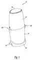
- FIG. 1is a top perspective view of an exemplary embodiment of a waste disposal device according to the present disclosure
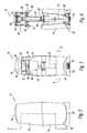
- FIG. 2is a side view of the waste disposal device of FIG. 1 shown in a closed or non-use position;
- FIG. 3is a front partial sectional view of the waste disposal device of FIG. 2 taken along lines 3 - 3 ;
- FIG. 4is a rear view of the waste disposal device of FIG. 3 ;
- FIG. 5is side view of the waste disposal device of FIG. 1 shown in a partially open position
- FIG. 6is a partial sectional view of the waste disposal device of FIG. 5 taken along lines 6 - 6 ;
- FIG. 7is a rear view of the waste disposal device of FIG. 6 ;
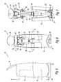
- FIG. 8is a side view of the waste disposal device of FIG. 1 shown in a fully open or use position;
- FIG. 9is a partial sectional view of the waste disposal device of FIG. 8 taken along lines 9 - 9 ;
- FIG. 10is a rear view of the waste disposal device of FIG. 9 ;
- FIG. 11is a close-up view of portions of a first exemplary embodiment of a bucket assembly shown in the closed or non-use position;
- FIG. 12is a close-up view of portions of the bucket assembly fully shown in the open or use position
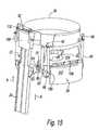
- FIG. 13is a top, front perspective view of portions of the bucket assembly, the cassette, and the upper push rod according to the present disclosure
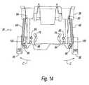
- FIG. 14is a rear view of portions of the bucket assembly, which is shown in the closed or non-use position;
- FIG. 15is a rear perspective view of the upper push rod shown and portions of the bucket assembly, which is shown in the closed or non-use position;
- FIG. 16is a front view of the bucket assembly having an exemplary embodiment of a warning device
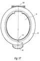
- FIG. 17is a top view of the waste disposal device illustrating the warning device of FIG. 16 ;
- FIG. 18Ais a top, front perspective view of an exemplary embodiment of lower housing according to the present disclosure.
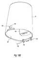
- FIG. 18Bis a bottom, front perspective view of an exemplary embodiment of lower housing according to the present disclosure.
- FIG. 19is a side view of the relationship between a hinge assembly and a push rod of FIG. 18 ;
- FIG. 20is a top perspective view of a lid retaining mechanism according to the present disclosure.
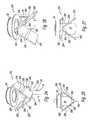
- FIG. 21is a bottom, front perspective view of a cutter assembly according to the present disclosure.
- FIG. 22is a bottom, rear perspective view of the cutter assembly of FIG. 21 ;
- FIG. 23is an exploded view of the cutter assembly of FIG. 21 ;
- FIG. 24is a perspective view of a second exemplary embodiment of a bucket assembly according to the present disclosure shown in the open or use position;
- FIG. 25is a front view of the bucket assembly of FIG. 24 ;
- FIG. 26is a perspective view of the bucket assembly of FIG. 24 shown in the closed or non-use position
- FIG. 27is a front view of the bucket assembly of FIG. 26 ;
- FIG. 28is a perspective view of a third exemplary embodiment of a bucket assembly according to the present disclosure shown in the open or use position;
- FIG. 29is a front view of the bucket assembly of FIG. 28 ;
- FIG. 30is a perspective view of the bucket assembly of FIG. 28 shown in the closed or non-use position
- FIG. 31is a front view of the bucket assembly of FIG. 30 ;
- FIG. 32is a perspective view of a fourth exemplary embodiment of a bucket assembly according to the present disclosure shown in the open or use position;
- FIG. 33is a front view of the bucket assembly of FIG. 32 ;
- FIG. 34is a perspective view of the bucket assembly of FIG. 32 shown in the closed or non-use position
- FIG. 35is a front view of the bucket assembly of FIG. 34 ;
- FIG. 36is a perspective view of a fifth exemplary embodiment of a bucket assembly according to the present disclosure shown in the open or use position;
- FIG. 37is a front view of the bucket assembly of FIG. 36 ;
- FIG. 38is a perspective view of the bucket assembly of FIG. 36 shown in the closed or non-use position
- FIG. 39is a front view of the bucket assembly of FIG. 38 ;
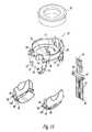
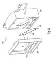
- FIG. 40is a bottom perspective view of a sixth alternate exemplary embodiment of a bucket assembly according to the present disclosure, illustrating the bucket assembly in a fully open or use position;
- FIG. 41is a top perspective view of bucket portions of the bucket assembly of FIG. 40 ;
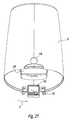
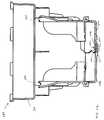
- FIG. 42is a sectional view of the bucket assembly of FIG. 40 ;
- FIG. 43is a top perspective view of the bucket portions of FIG. 41 , illustrated the bucket assembly in a closed or non-use position;
- FIG. 44is a sectional view of an alternate embodiment of the bucket assembly of FIG. 40 in the closed or non-use position.
- an exemplary embodiment of a waste disposal device according to the present disclosureis generally referred to by reference numeral 10 .
- waste disposal device 10is configured so that depressing a foot pedal causes a lid to open and causes an internal waste bucket assembly to move to an open position for receipt of the waste therein. After placing the waste in the open bucket assembly and releasing the foot pedal, the lid closes automatically, while the bucket assembly returns to a normal or closed position.
- the internal waste bucket assemblyforms a pressure or pinch seal of the waste liner in both its open and closed positions, which mitigates odor emanation.
- waste disposal device 10includes an upper housing 12 , a lower housing 14 , a lid 16 , and a foot pedal 18 .
- lower housing 14can include a shroud 20 to increase the stability of the device 10 during use.
- Shroud 20can be integral with or separate from lower housing 14 .
- Shroud 20can increase the stability of waste disposal device 10 by increasing the weight of the device, increasing the base footprint of the device, or any combinations thereof.
- Upper housing 12includes an opening where lid 16 is pivotally secured to the upper housing at the opening to selectively open and close the opening. When lid 16 is open, the lid allows access to an inner storage area defined by upper and lower housings 12 , 14 via the housing opening.
- FIGS. 2 through 10illustrate waste disposal device 10 in a closed or non-use position.
- FIGS. 5 through 7illustrate waste disposal device 10 in a mid-position between the open and closed positions.
- FIGS. 8 through 10illustrate waste disposal device 10 in an open or use position.
- Pedal 18is pivotally secured to lower housing 14 for movement between a normal or upper position ( FIGS. 2-4 ) and a use or lower position ( FIGS. 8-10 ).
- Pedal 18is operatively associated with lid 16 so that when the pedal is in the normal or upper position ( FIGS. 2-4 ), the lid is in a closed position ( FIGS. 2-4 ).
- pedal 18is operatively associated with lid 16 so that when the pedal is in the use or lower position ( FIGS. 8-10 ), the lid is in an open position ( FIGS. 8-10 ).
- waste disposal device 10includes a lower push rod 22 and an upper push rod 24 .
- Lower push rod 22has a lower end 26 and an upper end 28 .
- upper push rod 24has a lower end 30 and an upper end 32 .
- Lower end 26 of the lower push rod 22is operatively connected to pedal 18
- upper end 32 of the upper push rod 24is operatively connected to lid 16 .
- upper end 28 of the lower push rod 22is operatively associated with lower end 30 of the upper push rod 24 .
- movement of foot pedal 18 in a downward direction (A)moves lower push rod 22 in an upward direction (B), which in turn moves upper push rod 24 in the upward direction.
- Movement of upper push rod 24 in the upward direction (B)causes upper end 32 of the upper push rod to act on lid 16 so as to move the lid from the closed position ( FIG. 2 ) to the open position ( FIG. 8 ).
- Waste disposal device 10includes a waste bucket assembly 34 that is also operatively associated with pedal 18 .
- Waste bucket assembly 34includes a bucket frame 36 , a first bucket portion 38 , and a second bucket portion 40 .
- First and second bucket portions 38 , 40are pivotally secured to bucket frame 36 for movement between a closed or non-use position ( FIGS. 2-4 ) and an open or use position ( FIGS. 8-10 ).
- foot pedal 18 in downward direction (A)moves lower push rod 22 in an upward direction (B), which in turn moves upper push rod 24 in the upward direction.
- Movement of upper push rod 24 in the upward direction (B)causes the upper push rod to act on assembly 34 to move first and second bucket portions 38 , 40 from the closed or non-use position to the open or use position.
- waste disposal device 10allows for easy, hands free operation by merely stepping on or otherwise moving foot pedal 18 in the downward direction (A).
- waste bucket assembly 34removably receives a cassette 42 in bucket frame 36 in a known manner.
- Cassette 42houses a length or supply of liner material 44 , in the form of tubular stock in a folded or pleated position within the cassette, for the incremental withdrawal of portions thereof in a known manner.
- cassette 42can be one as disclosed in commonly owned U.S. Pat. Nos. 6,170,240, 7,073,311, 7,100,767, and U.S. patent application Ser. No. 11/800,324, the entire contents of each of which are incorporated by reference herein.
- Cassette 42can be removed and replaced as needed.
- cassette 42can be replaced by simply opening lid 16 , removing the empty cassette 42 from bucket frame 36 , placing a full cassette 42 into the bucket frame, and closing the lid 16 .
- bucket frame 36secures an open end 62 of liner material 44 between lid 16 and bucket portions 38 , 40 .
- a userinstalls cassette 42 in bucket frame 36 , withdraws a length of liner material 44 from the cassette, feeds the length of liner material 44 through bucket portions 38 , 40 so that the open end is in lower housing 14 , and closes or seals off the open end of the liner material 44 with, for example, a knot 46 .
- waste 50such as, but not limited to, disposable diapers, nappies, training pants, and incontinence products
- the usermerely opens lid 16 by stepping on or otherwise depressing pedal 18 . In this position, first and second bucket portions 38 , 40 are in the open or use position illustrated in FIG. 12 , as well as FIGS. 8 through 10 .
- the userthen places waste 50 into liner material 44 , which is located within the open first and second bucket portions 38 , 40 .
- the usermerely releases foot pedal 18 , at which time, lid 16 closes and first and second bucket portions 38 , 40 move to the closed position as seen in FIG. 11 , as well as FIGS. 2 through 4 .
- waste 50is urged into the inner storage area 52 of device 10 . Further, waste 50 is urged into the inner storage area 52 of device 10 due to gravitational force acting on the waste.
- Waste 50is maintained within liner material 44 between knot 46 and a first pinch closure 54 .
- First pinch closure 54is defined by leading edges 58 , 60 of first and second bucket portions 38 , 40 , respectively as shown in FIG. 11 .
- the pressure of first pinch closure 54is maintained by the spring force of biasing members 48 .
- device 10provides first pinch closure 54 with a closing force of between about 0.5 pounds to about 5 pounds, more preferably between about 1.25 pounds to about 2 pounds, and all subranges therebetween. As used herein with respect to the closing force, the term about shall mean ⁇ 0.1 pounds or less.
- first pinch closure 54provides a seal having a surface area of about 0.25 square inches (in 2 ) to about 0.5 in 2 , more preferably about 0.375 in 2 , and any subranges therebetween.
- the term aboutshall mean ⁇ 0.1 inches or less.
- first pinch closure 54mitigates the emanation of odor from waste 50 from inner storage area 52 when device 10 is closed.
- Second pinch closure 64is defined by trailing edges 68 , 70 of first and second bucket portions 38 , 40 , respectively as shown in FIG. 12 .
- the pressure of second pinch closure 64is defined by the pressure applied by the user on foot pedal 18 .
- device 10provides second pinch closure 64 with a closing force of between about 0.5 pounds to about 5 pounds, more preferably between about 3.5 pounds to about 4.5 pounds, and all subranges therebetween.
- second pinch closure 64provides a seal having a surface area of about 0.25 in 2 to about 0.5 in 2 , more preferably about 0.375 in 2 , and any subranges therebetween.
- second pinch closure 64mitigates the emanation of odor from waste 50 from inner storage area 52 when device 10 is open.
- waste disposal device 10when not in use, reduces odors emanating from waste 50 collected within liner material 44 by forming first pinch closure 54 . Further, waste disposal device 10 , when in use, reduces odors emanating from waste 50 collected within liner material 44 by forming second pinch closure 64 .
- waste disposal device 10 of present disclosureis described above by way of example making use of cassette 42 and liner material 44 . However, it is contemplated by the present disclosure for device 10 to find equal use with any liner material 44 such a plastic trash bag configured to be received by device 10 . In this embodiment, device 10 does not require cassette 42 , but rather liner material 44 has an upper end secured at bucket frame 36 above first and second pinch closures 54 , 64 .
- the cassettecan include liner material 44 having a pressure sensitive adhesive system 56 disposed thereon.
- System 56is defined on liner material 44 so that the system is internal to the liner material.
- system 56adhesively seals liner material 44 to itself due to the pressure applied by first pinch closure 54 , second pinch closure 64 , or any combinations thereof.
- suitable pressure sensitive adhesive systems 56 contemplated by the present disclosureinclude those described in U.S. Pat. Nos. 5,662,758, 5,965,235, 6,194,062, and 6,489,022, the entire contents of each of which are incorporated by reference herein.
- odor from waste 50 collected within liner material 44is not only prevented from emanating due to first and second pinch closures 54 , 64 but also due to the adhesive seal, above and/or below each piece of waste 50 , that is created by the interaction of the pinch closures with pressure sensitive adhesive system 56 .
- Bucket frame assembly 34is secured inside of upper housing 14 proximate lid 16 , while first and second bucket portions 38 , 40 are pivotally secured to bucket frame 36 .
- Bucket frame 36includes a pair of first pivot openings 72 , a pair of second pivot openings 74 , a pair of first cam slots 76 , and a pair of second cam slots 78 .
- First bucket portion 38includes a pair of first pivot members 82 and a pair of first cam members 84 .
- second bucket portion 40includes a pair of second pivot members 86 and a pair of second cam members 88 .
- First bucket portion 38is received in bucket frame 36 so that first pivot members 82 are pivotally received in first pivot openings 72 , respectively, and so that first cam members 84 are received in first cam slots 76 .
- second bucket portion 40is received in bucket frame 36 so that second pivot members 86 are pivotally received in second pivot openings 74 , respectively, and so that second cam members 88 are received in second cam slots 78 .
- first bucket portion 38rotates in bucket frame 36 about first pivot members 82
- second bucket member 40rotates in the bucket frame 36 about second pivot members 86 .
- the rotation of first and second bucket portions 38 , 40are defined by the interaction of cam slots 76 , 78 with cam members 84 , 88 .
- Cam members 84 , 88extend through bucket frame 36 so that an extended portion 90 is defined on an exterior of the bucket frame ( FIG. 15 ).
- Upper push rod 24includes a surface 92 that is operatively associated with extension member 90 . In this manner, movement of upper push rod 24 in the upward direction (B) causes surface 92 to push extended portion 90 in the upward direction so that cam members 84 , 88 travel along or follow cam slots 76 , 78 , respectively. Movement of extended portion 90 in the upward direction (B) causes first and second bucket portions 38 , 40 to rotate about pivot members 82 , 86 , respectively.
- push rod 24is effective at moving first and second bucket portions 38 , 40 from the closed position ( FIG. 11 ) to the open position ( FIG. 12 ).
- Bucket assembly 34also includes one or more biasing members 48 for each bucket portion 38 , 40 .
- bucket assembly 34includes two biasing members 48 for first bucket portion 38 and two biasing members 48 for second bucket portion 40 .
- biasing members 48are shown as tension springs.
- other biasing members 48such as, but not limited, to elastic bands, rotary springs, or any combinations thereof are contemplated by the present disclosure.
- Biasing members 48are configured to return bucket portions 38 , 40 from the open position to the closed position upon release of pressure from foot pedal 18 . Further, biasing members 48 are configured to return lid 16 from the open position to the closed position upon release of pressure from foot pedal 18 and are configured to return foot pedal 18 to its normal or lower position.
- Bucket frame 36includes retainers 96 configured to secure an upper end of biasing members 48 to the bucket frame as shown in FIGS. 13-15 .
- First and second bucket portions 38 , 40each include retainers 98 configured to secure a lower end of biasing members 48 to the first and second bucket portions, respectively.
- first and second bucket portions 38 , 40each include a fulcrum member 100 . Fulcrum member 100 transmits the biasing or spring force of biasing members 48 onto first and second bucket portions 38 , 40 in an outward direction (C).
- biasing members 48normally bias lid 16 and bucket assembly 34 to the closed or non-use position ( FIG. 3 ).
- extended portion 90 of the bucket assemblyis operatively associated with surface 92 of upper push rod 24 to bias the upper push rod in the downward direction (A), which in turn biases lower push rod 22 in the downward direction (A) and foot pedal 18 to its normal or upper position ( FIG. 3 ).
- a userapplies an amount of pressure to foot pedal 18 that is sufficient to overcome the biasing or spring force of biasing members 48 .
- lid 16 and bucket assembly 36move to the open or use position.
- releasing the pressure from foot pedal 18results in the biasing or spring force of biasing members 48 to return lid 16 and bucket assembly 36 to the closed or non-use position and pedal to the normal or upper position.
- first and second bucket portions 38 , 40can, in some embodiments, each be formed of a lower section 102 and an upper section 104 that are secured to one another by a hinge 106 .
- lower section 102 and upper section 104are maintained by biasing members 48 in a generally perpendicular relationship to one another so that first and second bucket portions 38 , 40 define a generally L-shaped member.
- a usercan push on waste 50 so as to overcome the biasing or spring force of biasing members 48 .
- Overcoming the biasing or spring force of biasing members 48causes lower section 102 to rotate with respect to upper section 104 about hinge 106 so that the lower and upper sections move to a generally linear relationship to one another.
- waste disposal device 10includes a warning system 110 .
- Warning system 110alerts a user to a condition where bucket portions 38 , 40 remain in an open or partially open state so that first pinch closure 54 is not formed.
- Warning system 110includes an indicator device 112 , one or more switches 114 (only one shown), and a power source 116 .
- Indicator device 112can be a sensory device, including, but limited to, a lighting device such as a light emitting diode (LED), an audible device such as a speaker, or any combinations thereof.
- indicator device 112is shown as an LED 118 protruding through an opening in upper housing 14 .
- Power source 116can be any source of electrical energy such as, but not limited to, a battery, a power cord configured to electrically communicate with an electrical outlet, or any combinations thereof.
- Switch 114is positioned on bucket assembly 34 to detect the position of first cam member 84 and/or second cam member 88 .
- switch 114is positioned to be contacted by first cam member 84 and/or second cam member 88 when the cam members bucket portions 38 , 40 are in the closed or non-use position.
- switch 114it is contemplated by the present disclosure for switch 114 to be in any desired position sufficient to detect the position of bucket portions 38 , 40 .
- switch 114it is contemplated by the present disclosure for switch 114 to sense the position of bucket portions 38 , 40 directly at the sealing surfaces (i.e., first and/or second pinch closures 54 , 64 ) or indirectly at a location remote from the sealing surfaces such as at cam members 84 , 88 or any other moveable portion of bucket assembly 34 .
- switch 114it is contemplated by the present disclosure for switch 114 to include any type of switching device such as contact switches, magnetic sensing devices, optical sensing devices, or any combinations thereof.
- first and second bucket portions 38 , 40may not close completely so that first pinch closure 54 is not formed.
- Switch 114places power source 116 in electrical communication with indicator device 112 when the switches do not detect the presence of first and/or second cam members 84 , 88 .
- warning system 110indicates to the user, via indicator device 112 , that the bucket portions 38 , 40 are open. In the event that lid 16 is closed and the indicator device 112 is activated, the user knows that a jam or full condition has occurred.
- warning system 110can further include a circuit 120 configured to minimize the use of power source 116 .
- Circuit 120can be particularly useful to conserve energy when power source 116 is a battery.
- circuit 120waits a predetermined time period, such as about 15 seconds, after switch 114 no longer detects the presence of first and/or second cam members 84 , 88 before activating indicator device 112 .
- circuit 120can be configured to cycle indicator device 112 between an activated and inactivated state after switch 114 no longer detects the presence of first and/or second cam members 84 , 88 to further reduce the consumption of energy from power source 116 .
- warning system 110is configured so that switch 114 does not place circuit 120 in electrical communication with power source 116 until the switch no longer detects the presence of first and/or second cam members 84 , 88 . In this manner, circuit 120 does not consume energy from power source 116 until the open or jam condition occurs.
- switch 114can further detect whether lid 16 is in the closed position. In this manner, warning system 110 can alert a user to a condition where lid 16 has returned to the closed position, but bucket portions 38 , 40 remain in an open or partially open state so that first pinch closure 54 is not formed.
- indicator device 112will only be activated when the lid is closed and first pinch closure 54 is not formed.
- waste disposal device 10includes a hinge 124 and a locking device 126 .
- Hinge 124secures lower housing 14 to upper housing 12 allowing the upper housing to be pivoted away from the lower housing so that waste 50 collected within inner storage area 52 can be easily removed.
- Locking device 126releasably secures lower housing 14 to upper housing 12 so that waste disposal device 10 remains in a closed state until the user disengages the locking device.
- Hinge 124includes a lower hinge member 128 disposed on lower housing 14 and an upper hinge member 130 disposed on upper housing 12 .
- Lower and upper hinge members 128 , 130are rotatably secured to one another in a known manner by a hinge pin 132 .
- Locking device 126includes a first locking member 134 on lower housing 14 and a second locking member 136 on upper housing 12 .
- second locking member 136is illustrated as an opening 138
- first locking member 134is illustrated as a tab 140 having a rim 142 defined thereon.
- Tab 140includes a flexible region 144 , which acts as a cantilever beam, so that the tab can flex radially inward until rim 142 is received in opening 138 at which time the resiliency of region 144 biases the rim radially outward into the opening.
- the usermerely applies pressure to tab 140 to flex region 144 radially inward until rim 144 is free from opening 138 , thus allowing upper housing 12 to be rotated about hinge 124 .
- waste disposal device 10is configured to mitigate regions from which odor can emanate by maintaining lower and upper push rods 22 , 24 internal to storage area 52 , namely within upper and lower housings 12 , 14 as shown in FIG. 19 .
- the devicecan include a first guide 146 for lower push rod 22 and a second guide 148 for upper push rod 24 .
- First and second guides 146 , 148slideably receive lower and upper push rods 22 , 24 , respectively therethrough and assist in maintaining the upper end 28 of the lower push rod aligned with the lower end 30 of upper push rod.
- hinge 124 and first guide 146 for lower push rod 22are integrally formed with one another as shown in FIG. 19 . This integral unit locks to lower housing 14 at its upper end so that hinge member 128 extends outside of the lower housing.
- Second guide 146can be secured to bucket frame 36 in any desired manner.
- second guide 146can be integral with bucket frame 36 or can be secured to the bucket frame by connectors such as, but not limited to screws or bolts.
- Hinge 124includes an axis of rotation 150 that is external to device 10 , while the operative association of upper end 28 of lower push rod 22 with lower end 30 of upper push rod 24 is internal to device.
- axis of rotation 150is offset horizontally with respect to the interaction of ends 28 , 30 .
- Upper end 32includes one or more openings 152
- lid 16includes a corresponding number of projections 154 each having a cam surface 156 .
- upper push rod 24moves in the upward direction (B)
- upper end 32acts on cam surface 156 so as to open lid 16 .
- projections 154are received in openings 152 .
- the interaction of projections 154 and openings 152maintains upper push rod 24 in operative engagement with lid 16 .
- the interaction of projections 154 and openings 152prevents lid 16 from opening past a predetermined point.
- bucket frame 36may include an integral guide 158 ( FIG. 15 ) for upper push rod 24 .
- Guide 158slideably receives upper push rod 24 therethrough and assists in maintaining the upper end 32 of the upper push rod in alignment with projections 154 and surfaces 156 of lid 16 .
- waste disposal device 10Once inner storage area 52 is full, the user is required to open waste disposal device 10 and remove the portion of liner material 44 having waste 50 collected therein.
- the useropens waste disposal device 10 by operating locking device 126 and rotating upper housing 14 about hinge 124 . As the user rotates upper housing 14 about hinge 124 , additional liner material 44 is withdrawn from cassette.
- waste disposal device 10may include a cutter assembly 160 shown in FIGS. 21-23 .
- cutter assembly 160is secured to upper housing 14 at upper hinge member 130 , so that the cutter assembly swings with the upper housing up to allow the user easy access to the cutter assembly.
- Cutter assembly 160includes a front member 162 , a rear member 164 , and a blade 166 having a cutting edge 168 .
- Front and rear members 162 , 164include a liner opening 170 .
- Blade 166is secured between front and rear members 162 , 164 so that edge 168 of blade is protected or shielded by the front and rear members, but is exposed at opening 170 .
- the usercan slide liner material 44 into opening 170 in a cutting direction (D) so that the liner material is cut by blade edge 168 .
- the open end of the liner material containing waste 50can be closed using a knot and can be discarded.
- the open end of the portion of liner material 44 remaining in device 10can be closed with, for example, knot 46 , as previously described.
- one or more components of waste disposal device 10can include an antimicrobial additive incorporated directly into the material of the component.
- various components of waste disposal device 10can be formed from a polymer or plastic material having an antimicrobial additive incorporated directly into the polymer or plastic material.
- Suitable antimicrobials for use in the present disclosureinclude, but are not limited to, those sold under the tradename Microban® and those sold under the tradename Ultra-Fresh®.
- Ultra-Fresh® SA-18is a silver refractory antimicrobial that is useful in the present disclosure.
- the components of device 10can be made of polypropylene, acrylonitrile butadiene styrene (ABS) material, or any combinations thereof.
- ABSacrylonitrile butadiene styrene
- any plastic or polymer component of device 10such as, but not limited to, upper housings 14 , lower housing 12 , lid 16 , foot pedal 18 , shroud 20 , push rods 22 , 24 , bucket assembly 34 , cassette 42 , liner material 44 , pressure sensitive adhesive system 56 , or any combinations thereof, to include one or more antimicrobials mixed directly into the plastic or polymer.
- one or more antimicrobials having metal particlesare mixed directly into the plastic or polymer so that at least a portion of the metal particles protrude from the plastic or polymer.
- any component of device 10to include an antimicrobial additive incorporated directly onto the surface of the component.
- waste disposal device 10can inhibit microbial growth on the internal and external surfaces of any component including the antimicrobial additive, which further reduces or mitigates the odors emanating from the device.
- waste disposal device 10having merely an exemplary embodiment of bucket assembly 34 , where first and second pinch closures 54 , 64 are formed by first and second bucket portions 38 , 40 .
- waste disposal device 10it is contemplated by the present disclosure for waste disposal device 10 to include any bucket assembly 34 configured to form first pinch closure 54 when lid 16 is in the closed position and second pinch closure 64 when the lid 16 is in the open position, all as a result of the simple movement of foot pedal 18 .
- FIGS. 24-43alternate exemplary embodiments of bucket assemblies for use with waste disposal device 10 are shown in FIGS. 24-43 .
- FIGS. 24-27an alternate exemplary embodiment of a bucket assembly according to the present disclosure is shown and generally referred to by reference numeral 234 .
- reference numeral 234For purposes of clarity, various elements of waste disposal device 10 have been omitted. Rather, bucket assembly 234 is shown in relation only to cassette 42 and upper push rod 24 .
- Bucket assembly 234includes a first member 238 and a second member 240 .
- First and second members 238 , 240are secured to the bucket frame (not shown) for rotation between a closed or non-use position ( FIGS. 26-27 ) and an open or use position ( FIGS. 24-25 ). In the closed position, first and second members 238 , 240 form a first pinch closure 254 , while in the open position the first and second members form a second pinch closure 264 .
- Bucket assembly 234includes one or more biasing members 248 biasing first and second members 238 , 240 to the closed position.
- biasing members 248include torsion springs.
- First and second members 238 , 240each include an extended portion 290 that is in operative engagement with a surface 292 of upper push rod 24 .
- the operative engagement between extended portion 290 and surface 292is a rack-and-pinion arrangement that rotates first and second members 238 , 240 upon movement of upper push rod 24 in the downward and upward directions (A, B) respectively.
- the operative engagement between extended portion 290 and surface 292can be a friction arrangement that rotates first and second members 238 , 240 upon movement of upper push rod 24 .
- First and second members 238 , 240can, in some embodiments, each be formed of a lower section 202 and an upper section 204 that are secured to one another by a hinge 206 .
- lower section 202 and upper section 204are maintained by biasing members 248 in a generally parallel relationship to one another so that first and second bucket portions 238 , 240 define a generally linear shaped member.
- a usercan push on the lower section 202 so as to overcome the biasing or spring force of biasing members 248 .
- Overcoming the biasing or spring force of biasing members 248causes lower section 202 to rotate with respect to upper section 204 about hinge 206 .
- biasing members 248have been described as biasing first and second members 238 , 240 to the closed position and biasing lower and upper sections 202 , 204 to their normal liner shape. Of course, it is contemplated for these biasing functions to be achieved by separate biasing members 248 . In addition, it is contemplated for lower and upper sections 202 , 204 to be integrally formed with hinge 206 so that the hinge is merely an elastically deformable portion of first and second members 238 , 240 , respectively.
- FIGS. 28-31another alternate exemplary embodiment of a bucket assembly according to the present disclosure is shown and generally referred to by reference numeral 334 . Again, various elements of waste disposal device 10 have been omitted for purposes of clarity. Rather, bucket assembly 334 is shown in relation only to cassette 42 and upper push rod 24 .
- Bucket assembly 334includes a first member 338 and a second member 340 .
- First and second members 338 , 340are secured to the bucket frame (not shown) for movement between a closed or non-use position ( FIGS. 30-31 ) and an open or use position ( FIGS. 28-29 ). In the closed position, first and second members 338 , 340 forms a first pinch closure 354 , while in the open position the first and second members form a second pinch closure 364 .
- First and second members 338 , 340are formed of a lower section 302 and an upper section 304 .
- Lower sections 302are secured to the bucket frame (not shown) for rotation between the closed and open positions.
- Upper sections 304are secured to the bucket frame (not shown) for movement in a radial direction (E) between the closed and open positions.
- lower section 302 and an upper section 304are operatively engaged with one another so that rotation of the lower section results in the movement of the upper section in the radial direction (E).
- the operative engagement between lower section 302 and an upper section 304is a rack-and-pinion arrangement configured so that rotation of the lower section results in the radial movement of the upper section.
- Bucket assembly 334includes one or more biasing members 348 configured to bias first and second members 338 , 340 to the closed position.
- biasing members 348include torsion springs.
- First and second members 338 , 340each include an extended portion 390 that is in operative engagement with a surface 392 of upper push rod 24 .
- the operative engagement between extended portion 390 and surface 392is a rack-and-pinion arrangement configured to rotate first and second members 338 , 340 upon movement of upper push rod 24 in the downward and upward directions (A, B) respectively.
- the operative engagement between extended portion 390 and surface 392can be a friction arrangement configured to rotate first and second members 338 , 340 upon movement of upper push rod 24 .
- FIGS. 32-35yet another alternate exemplary embodiment of a bucket assembly according to the present disclosure is shown and generally referred to by reference numeral 434 .
- various elements of waste disposal device 10have been omitted for purposes of clarity. Rather, bucket assembly 434 is shown in relation only to cassette 42 and upper push rod 24 .
- Bucket assembly 434includes a first member 438 and a second member 440 .
- First and second members 438 , 440are secured to the bucket frame (not shown) for movement between a closed or non-use position ( FIGS. 34-35 ) and an open or use position ( FIGS. 32-33 ). In the closed position, first and second members 438 , 440 form a first pinch closure 454 , while in the open position the first and second members form a second pinch closure 464 .
- First and second members 438 , 440include a flexible member 402 , a linkage 404 , and a shaft 406 .
- Shaft 406is rotatably secured to the bucket frame (not shown).
- Linkage 404operatively connects shaft 406 to flexible member 402 .
- Flexible member 402resiliently inverts between a concave shape ( FIGS. 32-33 ) and a convex shape ( FIGS. 34-35 ).
- the resilient nature of flexible member 402biases first and second members 438 , 440 to the closed position.
- Shaft 406includes an extended portion 490 that is in operative engagement with a surface 492 of upper push rod 24 .
- the operative engagement between extended portion 490 and surface 492is a rack-and-pinion arrangement that rotates first and second members 438 , 440 upon movement of upper push rod 24 in the downward and upward directions (A, B) respectively.
- the operative engagement between extended portion 490 and surface 492can be a friction arrangement that rotates first and second members 438 , 440 upon movement of upper push rod 24 .
- a fifth exemplary embodiment of a bucket assembly according to the present disclosureis shown and generally referred to by reference numeral 534 .
- various elements of waste disposal device 10have been omitted for purposes of clarity. Rather, bucket assembly 534 is shown in relation only to cassette 42 and upper push rod 24 .
- Bucket assembly 534includes a pair of first members 538 and a pair of second members 540 .
- First and second members 538 , 540are secured to the bucket frame (not shown) for movement in a radial direction (E) rotation between a closed or non-use position ( FIGS. 38-39 ) and an open or use position ( FIGS. 36-37 ).
- first members 538form a first pinch closure 554
- second members 540form a second pinch closure 564 .
- First and second members 538 , 540each include an extended portion 590 that is in operative engagement with a surface 592 of upper push rod 24 .
- surfaces 592are shown as cam slots in which portion 590 extends.
- bucket assembly 534includes a stationary guide plate 550 having guide slots 552 in which portion 590 also extends.
- Movement of upper push rod 24 in the downward direction (A)causes, due to the interaction of cam slots 592 and guide slots 552 , to urge first and second members 538 , 540 to the closed position shown in FIG. 38 .
- movement of upper push rod 24 in the upward direction (B)causes, due to the interaction of cam slots 592 and guide slots 552 , to urge first and second members 538 , 540 to the open position shown in FIG. 36 .
- Bucket assembly 534includes one or more biasing members 548 ( FIG. 38 ) biasing first and second members 538 , 540 to the closed position.
- biasing members 548are shown as elastic bands.
- other biasing members 548such as, but not limited, to tension springs, compression springs, rotary springs, or any combinations thereof are contemplated by the present disclosure.
- cam slots 592control the opening and closing of first and second members 538 , 540 faster than the opening and closing of the lid (not shown) of the waste disposal device.
- cam slots 592can be configured so that second pinch closure 564 is formed before lid is completely opened to mitigate emanation of odor from the waste disposal device.
- cam slots 592can be configured so that first pinch closure 554 is formed before lid is completely closed to mitigate emanation of odor from the waste disposal device.
- first and/or second members 538 , 540can include a resilient cover 556 ( FIG. 39 ) disposed thereon to assist in the formation first and second pinch closures 554 , 564 , respectively.
- resilient covers 556can include closed cell foam members disposed on first and/or second members 538 , 540 .
- Bucket assembly 634includes bucket frame 36 , a first bucket member 638 , and a second bucket member 640 .
- Bucket frame 36is discussed in detail above with respect to FIGS. 1-23 and, thus, further discussion of the bucket frame will be omitted hereinbelow.
- First and second bucket members 638 , 640are secured to the bucket frame 36 for rotation between an open or use position ( FIGS. 40-42 ) and a closed or non-use position ( FIG. 43 ). In the closed position of FIG. 43 , first and second members 638 , 640 form a first pinch closure 654 , while in the open position the first and second members form a second pinch closure 664 .
- first pinch closure 654mitigates the emanation of odor from the waste within the inner storage area when the waste disposal device is closed.
- First pinch closure 654is defined by leading edges 658 , 660 of first and second bucket portions 638 , 640 , respectively.
- leading edges 658 , 660each include a complimentary non-planar shape. In this manner, leading edges 658 , 660 define a longer pinch closure then would be otherwise provided with planar leading edges.
- leading edges 658 , 660each include a complimentary wave-like shape.
- leading edges 658 , 660to each include any complimentary non-planar shape such as, but not limited to, a square wave pattern, a saw tooth pattern, and any combinations thereof.
- first pinch closure 654The pressure of first pinch closure 654 is maintained by the spring force of biasing members 48 ( FIG. 11 ).
- device 10provides first pinch closure 654 with a closing force of between about 0.5 pounds to about 5 pounds, more preferably between about 1.25 pounds to about 2 pounds, and all subranges therebetween.
- first pinch closure 654provides a seal having a surface area of about 0.40 square inches (in 2 ) to about 1.50 in 2 , more preferably about 0.70 in 2 , and any subranges therebetween.
- Second pinch closure 664mitigates the emanation of odor from the waste within the inner storage area when the waste disposal device is opened during use. In the open position, the waste is maintained within the liner material between the knot and the second pinch closure 664 . Second pinch closure 664 is defined by trailing edges 668 , 670 of first and second bucket portions 638 , 640 , respectively as shown in FIGS. 40-42 .
- second pinch closure 664is formed by an overlapped area 690 of trailing edges 668 , 670 .
- first bucket portion 638includes a recessed area 692 , which is configured to receive a portion 694 of second bucket portion 640 .
- second pinch closure 664 formed by overlapped area 690further increases the surface area of the second pinch closure to mitigate the emanation of odor from the waste within the inner storage area.
- second pinch closure 660is further defined by trailing edges 668 , 670 of first and second bucket portions 638 , 640 , respectively.
- trailing edges 668 , 670each include a complimentary non-planar shape. In this manner, trailing edges 668 , 670 define a longer pinch closure then would be otherwise provided with planar trailing edges.
- trailing edges 668 , 670each include a complimentary wave-like shape.
- trailing edges 668 , 670to each include any complimentary non-planar shape such as, but not limited to, a square wave pattern, a saw tooth pattern, and any combinations thereof.
- the pressure of second pinch closure 664is defined by the pressure applied by the user on foot pedal 18 as discussed above.
- Second pinch closure 664having both overlapped area 690 and complimentary non-planar trailing edges 668 , 670 provides a seal having a surface area of about 2.50 in 2 to about 3.00 in 2 , more preferably about 2.90 in 2 , and any subranges therebetween.
- first pinch closure 654was described herein by way of example having complimentary non-planar leading edges 658 , 660 . However, it is also contemplated by the present disclosure for first pinch closure 654 to further include overlapped area 690 as shown in FIG. 44 . Further, it is contemplated by the present disclosure for overlapped area 690 to be omitted from second pinch closure 664 so that the second pinch closure 664 only includes complimentary non-planar trailing edges 668 , 670 .
Landscapes
- Engineering & Computer Science (AREA)
- Mechanical Engineering (AREA)
- Refuse Receptacles (AREA)
- Closures For Containers (AREA)
Abstract
Description
Claims (54)
Priority Applications (14)
| Application Number | Priority Date | Filing Date | Title |
|---|---|---|---|
| US12/080,178US8613371B2 (en) | 2007-11-16 | 2008-04-01 | Waste disposal devices for storage of waste in an inner storage area and methods |
| CN2008801247339ACN101910015B (en) | 2007-11-16 | 2008-11-14 | Waste treatment device and method |
| PCT/US2008/012824WO2009064483A1 (en) | 2007-11-16 | 2008-11-14 | Waste disposal devices and methods |
| KR1020127018757AKR20120097538A (en) | 2007-11-16 | 2008-11-14 | Waste disposal devices and methods |
| KR1020107012833AKR20100103507A (en) | 2007-11-16 | 2008-11-14 | Waste disposal devices and methods |
| CA2705794ACA2705794C (en) | 2007-11-16 | 2008-11-14 | Waste disposal devices and methods |
| CA2863260ACA2863260A1 (en) | 2007-11-16 | 2008-11-14 | Waste disposal devices and methods |
| JP2010534046AJP5335805B2 (en) | 2007-11-16 | 2008-11-14 | Waste treatment apparatus and method |
| MX2010005339AMX2010005339A (en) | 2007-11-16 | 2008-11-14 | Waste disposal devices and methods. |
| EP08849654.2AEP2219966A4 (en) | 2007-11-16 | 2008-11-14 | Waste disposal devices and methods |
| CN201310364577.6ACN103523358B (en) | 2007-11-16 | 2008-11-14 | Waste treatment apparatus |
| US14/073,151US9493302B2 (en) | 2007-11-16 | 2013-11-06 | Waste disposal services and methods |
| US14/551,706US20200172331A9 (en) | 2007-11-16 | 2014-11-24 | Waste Disposal Services and Methods |
| US15/281,422US20170015500A1 (en) | 2007-11-16 | 2016-09-30 | Waste Disposal Services and Methods |
Applications Claiming Priority (2)
| Application Number | Priority Date | Filing Date | Title |
|---|---|---|---|
| US11/985,734US20090126320A1 (en) | 2007-11-16 | 2007-11-16 | Waste disposal devices and methods |
| US12/080,178US8613371B2 (en) | 2007-11-16 | 2008-04-01 | Waste disposal devices for storage of waste in an inner storage area and methods |
Related Parent Applications (1)
| Application Number | Title | Priority Date | Filing Date |
|---|---|---|---|
| US11/985,734Continuation-In-PartUS20090126320A1 (en) | 2007-11-16 | 2007-11-16 | Waste disposal devices and methods |
Related Child Applications (1)
| Application Number | Title | Priority Date | Filing Date |
|---|---|---|---|
| US14/073,151ContinuationUS9493302B2 (en) | 2007-11-16 | 2013-11-06 | Waste disposal services and methods |
Publications (2)
| Publication Number | Publication Date |
|---|---|
| US20090127260A1 US20090127260A1 (en) | 2009-05-21 |
| US8613371B2true US8613371B2 (en) | 2013-12-24 |
Family
ID=40639038
Family Applications (1)
| Application Number | Title | Priority Date | Filing Date |
|---|---|---|---|
| US12/080,178Active2030-03-25US8613371B2 (en) | 2007-11-16 | 2008-04-01 | Waste disposal devices for storage of waste in an inner storage area and methods |
Country Status (8)
| Country | Link |
|---|---|
| US (1) | US8613371B2 (en) |
| EP (1) | EP2219966A4 (en) |
| JP (1) | JP5335805B2 (en) |
| KR (2) | KR20100103507A (en) |
| CN (2) | CN101910015B (en) |
| CA (2) | CA2705794C (en) |
| MX (1) | MX2010005339A (en) |
| WO (1) | WO2009064483A1 (en) |
Cited By (11)
| Publication number | Priority date | Publication date | Assignee | Title |
|---|---|---|---|---|
| US20120073250A1 (en)* | 2009-02-13 | 2012-03-29 | Nicholas Cudworth | Waste storage device |
| US20130298506A1 (en)* | 2010-12-17 | 2013-11-14 | Lencon Products B.V. | Device and method for the disposal of waste |
| US20150076153A1 (en)* | 2007-11-16 | 2015-03-19 | Eveready Battery Company, Inc. | Waste Disposal Services and Methods |
| US8984847B1 (en)* | 2011-05-20 | 2015-03-24 | Leo Nguyen | Liner sealing garbage container |
| USD795606S1 (en) | 2015-12-21 | 2017-08-29 | Sangenic International Limited | Cassette for a waste storage device |
| USD799136S1 (en) | 2015-12-21 | 2017-10-03 | Sangenic International Limited | Waste storage device |
| USD837473S1 (en) | 2017-04-11 | 2019-01-01 | Magnuson Group, Inc. | Waste receptacle |
| US10543982B2 (en) | 2017-05-23 | 2020-01-28 | Magnuson Group Inc. | Waste receptacle |
| USD992230S1 (en)* | 2020-01-04 | 2023-07-11 | Shanghai Townew Intelligent Technology Co Ltd. | Diaper pail |
| US20230242335A1 (en)* | 2022-02-03 | 2023-08-03 | Jason Craig Turman | Divided Trash Can |
| USD1077510S1 (en) | 2019-11-06 | 2025-06-03 | Munchkin, Inc. | Cassette |
Families Citing this family (31)
| Publication number | Priority date | Publication date | Assignee | Title |
|---|---|---|---|---|
| US8613371B2 (en)* | 2007-11-16 | 2013-12-24 | Eveready Battery Company, Inc. | Waste disposal devices for storage of waste in an inner storage area and methods |
| US20090126320A1 (en)* | 2007-11-16 | 2009-05-21 | Playtex Products, Inc. | Waste disposal devices and methods |
| EP2459449A1 (en)* | 2009-07-31 | 2012-06-06 | International Refills Company Ltd. | Waste disposal device |
| JP2011057382A (en)* | 2009-09-10 | 2011-03-24 | Aprica Children's Products Kk | Waste disposal apparatus |
| CA2751704C (en)* | 2011-09-06 | 2012-08-28 | Angelcare Development Inc. | Waste-disposal device |
| USD665551S1 (en) | 2011-09-19 | 2012-08-14 | Scandinavian Child Llc | Heat-sealed waste disposal |
| KR200469467Y1 (en)* | 2012-03-19 | 2013-10-14 | 아트플러스덴탈랩(주) | wastebasket of opening and closing in the central part |
| GB201220784D0 (en)* | 2012-11-19 | 2013-01-02 | Ocado Ltd | Bag handling apparatus |
| US9802755B2 (en)* | 2014-11-10 | 2017-10-31 | Edgewell Personal Care Brands, Llc | Waste disposal device |
| US20180065802A1 (en)* | 2015-03-22 | 2018-03-08 | Rotho Babydesign Gmbh | Method for converting secondary biological material into reusable energy and for storing said material, encasing method, and encasing device and encasing material herefor |
| USD826505S1 (en)* | 2016-07-08 | 2018-08-21 | Edgewell Personal Care Brands, Llc | Waste disposal device cover |
| USD825880S1 (en)* | 2016-07-08 | 2018-08-14 | Edgewell Personal Care Brands, Llc. | Waste disposal device cover |
| USD831290S1 (en)* | 2016-07-08 | 2018-10-16 | Edgewell Personal Care Brands, Llc. | Waste disposal device cover |
| USD824632S1 (en)* | 2016-07-08 | 2018-07-31 | Edgewell Personal Care Brands, Llc. | Waste disposal device cover |
| USD819916S1 (en)* | 2016-07-08 | 2018-06-05 | Edgewell Personal Care Brands, Llc. | Waste disposal device cover |
| USD838426S1 (en)* | 2016-07-08 | 2019-01-15 | Edgewell Personal Care Brands, Llc. | Waste disposal device cover |
| USD820546S1 (en)* | 2016-07-08 | 2018-06-12 | Edgewell Personal Care Brands, Llc. | Waste disposal device cover |
| CN109562893A (en)* | 2016-07-08 | 2019-04-02 | Edgewell个人护理品牌有限责任公司 | Waste treatment equipment |
| USD838075S1 (en)* | 2016-07-08 | 2019-01-08 | Edgewell Personal Care Brands, Llc. | Waste disposal device cover |
| USD830030S1 (en)* | 2016-07-08 | 2018-10-02 | Edgewell Personal Care Brands, Llc | Waste disposal device cover |
| USD820545S1 (en)* | 2016-07-08 | 2018-06-12 | Edgewell Personal Care Brands, Llc. | Waste disposal device cover |
| USD824631S1 (en)* | 2016-07-08 | 2018-07-31 | Edgewell Personal Care Brands, Llc. | Waste disposal device cover |
| USD837474S1 (en)* | 2016-07-08 | 2019-01-01 | Edgewell Personal Care, LLC | Waste disposal device cover |
| USD831291S1 (en)* | 2016-07-08 | 2018-10-16 | Edgewell Personal Care Brands, Llc. | Waste disposal device cover |
| USD829401S1 (en)* | 2016-07-08 | 2018-09-25 | Edgewell Personal Care Brands, Llc. | Waste disposal device cover |
| CA3113367A1 (en)* | 2018-09-20 | 2020-03-26 | Angelcare Canada Inc. | Waste disposal device and film dispensing cassette |
| TW202246417A (en) | 2021-03-05 | 2022-12-01 | 美商陶氏有機矽公司 | Curable silicone composition |
| CN116902292B (en)* | 2023-08-10 | 2025-08-08 | 深圳市朗科智能电气股份有限公司 | A vacuum packaging device |
| US20250066115A1 (en)* | 2023-08-21 | 2025-02-27 | Munchkin, Inc. | Waste containers with universal bag receptacle |
| CN117799981A (en)* | 2023-12-29 | 2024-04-02 | 江苏天泉宠物用品有限公司 | A pedal trash can |
| CN118220706B (en)* | 2024-05-23 | 2024-07-30 | 烟台康骨堂医药科技有限公司 | Garbage storage device for hospital nursing |
Citations (82)
| Publication number | Priority date | Publication date | Assignee | Title |
|---|---|---|---|---|
| US2811329A (en) | 1955-06-30 | 1957-10-29 | Fed Tool Corp | Step-on type waste receptacle unit |
| US4785964A (en) | 1987-10-19 | 1988-11-22 | Mobil Oil Corporation | Step-on wastebasket |
| US4869049A (en) | 1987-03-05 | 1989-09-26 | Process Improvements Limited | Apparatus and methods for using packs of flexible tubing in packaging |
| US4913308A (en) | 1989-04-28 | 1990-04-03 | Culbertson Russell D | Liner retainer apparatus and method |
| US4972966A (en) | 1990-01-12 | 1990-11-27 | Rubbermaid Incorporated | Step-on wastebasket |
| JPH039302A (en) | 1989-04-14 | 1991-01-17 | Carl Zeiss:Fa | Mirror for changing geometric shape of beam and surface treating method by laser |
| USD319905S (en) | 1989-01-13 | 1991-09-10 | Rubbermaid Incorporated | Step-on wastebasket |
| US5125526A (en) | 1991-11-21 | 1992-06-30 | Sumanis Arnold J | Waste receptacle with interior bag that is opened and closed automatically |
| US5147055A (en) | 1991-09-04 | 1992-09-15 | Gerry Baby Products Company | Diaper container |
| US5249693A (en) | 1992-09-24 | 1993-10-05 | Eagle Manufacturing Company | Plastic waste can for oily waste |
| JPH0656004A (en) | 1992-08-05 | 1994-03-01 | Asmo Co Ltd | Wiper for vehicle |
| JPH06156601A (en) | 1992-11-25 | 1994-06-03 | Matsushita Electric Works Ltd | Raw garbage receiving container |
| US5322225A (en) | 1991-05-23 | 1994-06-21 | Diatec Recycling Technologies Ltd. | Process of recycling of disposable diapers and the machine components thereof |
| US5348222A (en) | 1993-02-09 | 1994-09-20 | Roy Patey | Garbage container |
| JPH0761503A (en) | 1993-03-10 | 1995-03-07 | Matsushita Electric Works Ltd | Garbage accommodation compartment |
| US5429311A (en) | 1992-05-22 | 1995-07-04 | Dia Tec Recycling Technologies, Ltd. | Process of recycling of disposable diapers and the machine components thereof |
| USD368563S (en) | 1994-12-16 | 1996-04-02 | Rubbermaid Incorporated | Step-on wastebasket |
| JPH08133409A (en) | 1994-11-10 | 1996-05-28 | Asuberu Kk | Box for collection of sorted refuse |
| US5535913A (en) | 1994-10-20 | 1996-07-16 | Fisher-Price, Inc. | Odorless container |
| US5590512A (en) | 1994-08-26 | 1997-01-07 | Melrose Products Limited | Apparatus for using packs of flexible tubing in packaging |
| US5655680A (en) | 1994-10-20 | 1997-08-12 | Fisher Price, Inc. | Odorless container |
| US5662758A (en) | 1996-01-10 | 1997-09-02 | The Procter & Gamble Company | Composite material releasably sealable to a target surface when pressed thereagainst and method of making |
| US5813200A (en) | 1996-12-17 | 1998-09-29 | Mondial Industries, Ltd. | Packaging and disposal system |
| JPH1159635A (en) | 1997-08-25 | 1999-03-02 | Norio Hikichi | Processing device for bagging dirt |
| US5960710A (en) | 1995-04-04 | 1999-10-05 | Farnow Pty Limited | Refuse compactor |
| US5965235A (en) | 1996-11-08 | 1999-10-12 | The Procter & Gamble Co. | Three-dimensional, amorphous-patterned, nesting-resistant sheet materials and method and apparatus for making same |
| JP2000118604A (en) | 1998-10-06 | 2000-04-25 | Sekisui Chem Co Ltd | Garbage container |
| US6128890A (en) | 1998-02-09 | 2000-10-10 | Sangenic International Limited | Waste storage device |
| JP2001080705A (en) | 1999-09-09 | 2001-03-27 | Iwasaki Kogyo Kk | Two-stage refuse container with pedal |
| US6370847B1 (en) | 2000-10-02 | 2002-04-16 | Tim Allan Nygaard Jensen | Sealable diaper-disposal system and method |
| US20020066261A1 (en) | 1999-04-09 | 2002-06-06 | Richards David Charles | Waste storage device |
| JP2002337802A (en) | 2001-05-22 | 2002-11-27 | Matsushita Electric Ind Co Ltd | Packaging equipment |
| USD468507S1 (en) | 2001-12-12 | 2003-01-07 | Mcgee Rose | Sanitary wraps disposal unit |
| US6612099B2 (en) | 2001-05-02 | 2003-09-02 | Saniquest Industries Corp. | Waste disposal devices including cartridge of flexible tubing |
| US6626316B2 (en) | 2000-12-22 | 2003-09-30 | Frank Yang | Trash can assembly with toe-kick recess |
| USD481187S1 (en) | 2002-11-13 | 2003-10-21 | Hms Mfg. Co. | Step-on wastebasket |
| US20030213804A1 (en) | 2002-04-17 | 2003-11-20 | Chomik Richard S. | Disposable cassette for incremental withdrawal of tubular plastic with malodor-counteractant capacity |
| USD494722S1 (en) | 2003-08-29 | 2004-08-17 | Tsong-Yow Lin | Garbage can |
| US6851251B2 (en) | 2002-07-31 | 2005-02-08 | Saniquest Industries Corp. | Waste disposal devices |
| US20050044819A1 (en) | 2003-09-02 | 2005-03-03 | Chomik Richard S. | Waste storage device |
| US20050106706A1 (en) | 2001-04-10 | 2005-05-19 | Chomik Richard S. | Waste storage device |
| US6920994B2 (en) | 2003-04-18 | 2005-07-26 | Tsong-Yow Lin | Garbage storage device |
| US6925781B1 (en) | 2004-02-03 | 2005-08-09 | Playtex Products, Inc. | Integrated cutting tool for waste disposal method and apparatus |
| US20050183400A1 (en) | 2001-05-02 | 2005-08-25 | Playtex Products, Inc. | Waste disposal device including an external actuation mechanism to operate a cartridge |
| US20050183401A1 (en) | 2001-05-02 | 2005-08-25 | Playtex Products, Inc. | Waste disposal device including a film cutting and sealing device |
| US20050188661A1 (en) | 2001-05-02 | 2005-09-01 | Playtex Products, Inc. | Waste disposal device including rotating cartridge coupled to lid |
| US20050193692A1 (en) | 2001-05-02 | 2005-09-08 | Playtex Products, Inc. | Waste disposal device including rotating cartridge coupled to hinged lid |
| US20050193691A1 (en) | 2001-05-02 | 2005-09-08 | Stravitz David M. | Waste disposal device including a rotatable geared rim to operate a cartridge |
| US6941733B2 (en) | 2003-04-03 | 2005-09-13 | Playtex Products, Inc. | Waste disposal apparatus |
| US6974029B2 (en) | 2001-12-31 | 2005-12-13 | Moniteurs Angelcare Inc. | Cassette for dispensing pleated tubing |
| US20050274093A1 (en) | 2001-05-02 | 2005-12-15 | Playtex Products, Inc. | Waste disposal device including a mechanism for scoring a flexible tubing dispensed from a cartridge |
| US20060021301A1 (en) | 2001-05-02 | 2006-02-02 | Playtex Products, Inc. | Waste disposal device including a cartridge movable by rollers |
| US6993891B2 (en) | 2004-04-03 | 2006-02-07 | Bobbi Sue Richardson | Waste disposal system with flexible tubing |
| US7044323B2 (en) | 2003-12-23 | 2006-05-16 | Simplehuman Llc | Detachable foot pedal for trash can |
| USD522206S1 (en) | 2004-03-05 | 2006-05-30 | Simplehuman Llc | Foot pedal |
| USD522203S1 (en) | 2004-05-14 | 2006-05-30 | Viktor Lin | Pedal bin |
| US20060130439A1 (en) | 2001-05-02 | 2006-06-22 | Stravitz David M | Waste disposal device including a diaphragm for twisting a flexible tubing dispensed from a cartridge |
| US7073311B2 (en) | 2002-01-02 | 2006-07-11 | Playtex Products, Inc. | Odor control cassette |
| US7077283B2 (en) | 2003-07-07 | 2006-07-18 | Simplehuman Llc | Trash can assembly |
| USD526103S1 (en) | 2004-08-10 | 2006-08-01 | Sang Ah (Thai) Co., Ltd. | Round pedal bin |
| US7086569B2 (en) | 2003-01-06 | 2006-08-08 | Stravitz David M | All-purpose dispenser |
| US7086550B2 (en) | 2004-04-19 | 2006-08-08 | Simplehuman Llc | Trash can assembly with locking lid |
| US20060186121A1 (en) | 2005-02-18 | 2006-08-24 | Frank Yang | Trash can assembly with motion damper for lid |
| USD528727S1 (en) | 2004-11-22 | 2006-09-19 | Tsong-Yow Lin | Garbage can |
| USD528726S1 (en) | 2004-11-22 | 2006-09-19 | Tsong-Yow Lin | Garbage can |
| US7121421B2 (en) | 2003-11-19 | 2006-10-17 | Simplehumer, Llc | Trash can assembly |
| US20060237458A1 (en) | 2005-04-20 | 2006-10-26 | Frank Yang | Pedal assembly for trash can |
| US20060248862A1 (en) | 2005-04-25 | 2006-11-09 | International Refills Company Ltd. | Apparatus for packing disposable objects into an elongated tube of flexible material |
| USD532572S1 (en) | 2005-02-03 | 2006-11-21 | Tsong-Yow Lin | Garbage can |
| US20060273089A1 (en) | 2005-06-06 | 2006-12-07 | Chin-Fu Chiou | Cap of a garbage can |
| US7146785B2 (en) | 2001-05-02 | 2006-12-12 | Stravitz David M | Waste disposal devices |
| USD535450S1 (en) | 2005-05-03 | 2007-01-16 | Hua Wu Hardware Co., Ltd. | Garbage can |
| USD535449S1 (en) | 2005-05-03 | 2007-01-16 | Hua Wu Hardware Co., Ltd. | Garbage can |
| USD535796S1 (en) | 2005-03-08 | 2007-01-23 | Tsong-Yow Lin | Garbage can |
| US7225943B2 (en) | 2000-12-22 | 2007-06-05 | Simplehuman Llc | Trash can assembly and improvements thereto |
| US20070125782A1 (en) | 2005-11-01 | 2007-06-07 | Manufacturers Discount Furniture & Bedding, Inc. Dba India Ink | Container with foot-activated lid |
| US20070125792A1 (en) | 2005-11-03 | 2007-06-07 | Graco Children's Products Inc. | Diaper pail |
| US20070157581A1 (en) | 2003-10-23 | 2007-07-12 | Sangenic International Limited | Waste storage device |
| US20070175182A1 (en) | 2001-05-02 | 2007-08-02 | Playtex Products, Inc. | Waste disposal device including a sensing mechanism for delaying the rotation of a cartridge |
| US20070180798A1 (en) | 2001-05-02 | 2007-08-09 | Playtex Products, Inc. | Waste disposal device including a geared rotating cartridge |
| USD567467S1 (en) | 2007-04-19 | 2008-04-22 | Sinclair Worldwide, Inc. | Trash container |
| USD567466S1 (en) | 2007-04-19 | 2008-04-22 | Sinclair Worldwide, Inc. | Trash container |
Family Cites Families (5)
| Publication number | Priority date | Publication date | Assignee | Title |
|---|---|---|---|---|
| JPH039302U (en)* | 1989-06-15 | 1991-01-29 | ||
| JPH0656004U (en)* | 1993-01-08 | 1994-08-02 | 尚子 中田 | Garbage container with removable receiving tank |
| CN2242236Y (en)* | 1995-10-27 | 1996-12-11 | 林志南 | Refuse receptacle for indoor use |
| KR20050032963A (en)* | 2003-10-02 | 2005-04-08 | 공병원 | The rubbish bin having a agglutinant apparatus , cutter and cabinet door |
| US8613371B2 (en)* | 2007-11-16 | 2013-12-24 | Eveready Battery Company, Inc. | Waste disposal devices for storage of waste in an inner storage area and methods |
- 2008
- 2008-04-01USUS12/080,178patent/US8613371B2/enactiveActive
- 2008-11-14CNCN2008801247339Apatent/CN101910015B/ennot_activeExpired - Fee Related
- 2008-11-14EPEP08849654.2Apatent/EP2219966A4/ennot_activeWithdrawn
- 2008-11-14JPJP2010534046Apatent/JP5335805B2/ennot_activeExpired - Fee Related
- 2008-11-14CNCN201310364577.6Apatent/CN103523358B/ennot_activeExpired - Fee Related
- 2008-11-14KRKR1020107012833Apatent/KR20100103507A/ennot_activeAbandoned
- 2008-11-14MXMX2010005339Apatent/MX2010005339A/ennot_activeApplication Discontinuation
- 2008-11-14WOPCT/US2008/012824patent/WO2009064483A1/enactiveApplication Filing
- 2008-11-14CACA2705794Apatent/CA2705794C/enactiveActive
- 2008-11-14CACA2863260Apatent/CA2863260A1/ennot_activeAbandoned
- 2008-11-14KRKR1020127018757Apatent/KR20120097538A/ennot_activeCeased
Patent Citations (102)
| Publication number | Priority date | Publication date | Assignee | Title |
|---|---|---|---|---|
| US2811329A (en) | 1955-06-30 | 1957-10-29 | Fed Tool Corp | Step-on type waste receptacle unit |
| US4869049A (en) | 1987-03-05 | 1989-09-26 | Process Improvements Limited | Apparatus and methods for using packs of flexible tubing in packaging |
| US4785964A (en) | 1987-10-19 | 1988-11-22 | Mobil Oil Corporation | Step-on wastebasket |
| USD319905S (en) | 1989-01-13 | 1991-09-10 | Rubbermaid Incorporated | Step-on wastebasket |
| JPH039302A (en) | 1989-04-14 | 1991-01-17 | Carl Zeiss:Fa | Mirror for changing geometric shape of beam and surface treating method by laser |
| US4913308A (en) | 1989-04-28 | 1990-04-03 | Culbertson Russell D | Liner retainer apparatus and method |
| US4972966A (en) | 1990-01-12 | 1990-11-27 | Rubbermaid Incorporated | Step-on wastebasket |
| US5322225A (en) | 1991-05-23 | 1994-06-21 | Diatec Recycling Technologies Ltd. | Process of recycling of disposable diapers and the machine components thereof |
| US5147055A (en) | 1991-09-04 | 1992-09-15 | Gerry Baby Products Company | Diaper container |
| US5125526A (en) | 1991-11-21 | 1992-06-30 | Sumanis Arnold J | Waste receptacle with interior bag that is opened and closed automatically |
| US5429311A (en) | 1992-05-22 | 1995-07-04 | Dia Tec Recycling Technologies, Ltd. | Process of recycling of disposable diapers and the machine components thereof |
| JPH0656004A (en) | 1992-08-05 | 1994-03-01 | Asmo Co Ltd | Wiper for vehicle |
| US5249693A (en) | 1992-09-24 | 1993-10-05 | Eagle Manufacturing Company | Plastic waste can for oily waste |
| JPH06156601A (en) | 1992-11-25 | 1994-06-03 | Matsushita Electric Works Ltd | Raw garbage receiving container |
| US5348222A (en) | 1993-02-09 | 1994-09-20 | Roy Patey | Garbage container |
| JPH0761503A (en) | 1993-03-10 | 1995-03-07 | Matsushita Electric Works Ltd | Garbage accommodation compartment |
| US5590512A (en) | 1994-08-26 | 1997-01-07 | Melrose Products Limited | Apparatus for using packs of flexible tubing in packaging |
| US5655680A (en) | 1994-10-20 | 1997-08-12 | Fisher Price, Inc. | Odorless container |
| US5535913A (en) | 1994-10-20 | 1996-07-16 | Fisher-Price, Inc. | Odorless container |
| JPH08133409A (en) | 1994-11-10 | 1996-05-28 | Asuberu Kk | Box for collection of sorted refuse |
| USD368563S (en) | 1994-12-16 | 1996-04-02 | Rubbermaid Incorporated | Step-on wastebasket |
| US5960710A (en) | 1995-04-04 | 1999-10-05 | Farnow Pty Limited | Refuse compactor |
| US5662758A (en) | 1996-01-10 | 1997-09-02 | The Procter & Gamble Company | Composite material releasably sealable to a target surface when pressed thereagainst and method of making |
| US6489022B1 (en) | 1996-01-10 | 2002-12-03 | The Procter & Gamble Company | Composite material releasably sealable to a target surface when pressed thereagainst |
| US6194062B1 (en) | 1996-01-10 | 2001-02-27 | The Procter & Gamble Company | Storage wrap material |
| US5965235A (en) | 1996-11-08 | 1999-10-12 | The Procter & Gamble Co. | Three-dimensional, amorphous-patterned, nesting-resistant sheet materials and method and apparatus for making same |
| US6170240B1 (en) | 1996-12-17 | 2001-01-09 | Playtex Products, Inc. | Packaging and disposal system |
| US5813200A (en) | 1996-12-17 | 1998-09-29 | Mondial Industries, Ltd. | Packaging and disposal system |
| JPH1159635A (en) | 1997-08-25 | 1999-03-02 | Norio Hikichi | Processing device for bagging dirt |
| US6128890A (en) | 1998-02-09 | 2000-10-10 | Sangenic International Limited | Waste storage device |
| JP2000118604A (en) | 1998-10-06 | 2000-04-25 | Sekisui Chem Co Ltd | Garbage container |
| US20020066261A1 (en) | 1999-04-09 | 2002-06-06 | Richards David Charles | Waste storage device |
| US6994247B2 (en) | 1999-04-09 | 2006-02-07 | Melrose Products Limited | Waste storage device |
| US6719194B2 (en) | 1999-04-09 | 2004-04-13 | Melrose Products Limited | Waste storage device |
| JP2001080705A (en) | 1999-09-09 | 2001-03-27 | Iwasaki Kogyo Kk | Two-stage refuse container with pedal |
| US6370847B1 (en) | 2000-10-02 | 2002-04-16 | Tim Allan Nygaard Jensen | Sealable diaper-disposal system and method |
| US6516588B2 (en) | 2000-10-02 | 2003-02-11 | Tim Allan Nygaard Jensen | Sealable diaper-disposal system and method |
| US7225943B2 (en) | 2000-12-22 | 2007-06-05 | Simplehuman Llc | Trash can assembly and improvements thereto |
| US6626316B2 (en) | 2000-12-22 | 2003-09-30 | Frank Yang | Trash can assembly with toe-kick recess |
| US20050106706A1 (en) | 2001-04-10 | 2005-05-19 | Chomik Richard S. | Waste storage device |
| US20050183400A1 (en) | 2001-05-02 | 2005-08-25 | Playtex Products, Inc. | Waste disposal device including an external actuation mechanism to operate a cartridge |
| US20050193692A1 (en) | 2001-05-02 | 2005-09-08 | Playtex Products, Inc. | Waste disposal device including rotating cartridge coupled to hinged lid |
| US20040083681A1 (en) | 2001-05-02 | 2004-05-06 | Saniquest Industries Corp. | Cartridge of flexible tubing for waste disposal devices |
| US20070180798A1 (en) | 2001-05-02 | 2007-08-09 | Playtex Products, Inc. | Waste disposal device including a geared rotating cartridge |
| US6804930B2 (en) | 2001-05-02 | 2004-10-19 | Saniquest Industries Corp. | Waste disposal devices including cartridge of flexible tubing |
| US20060130438A1 (en) | 2001-05-02 | 2006-06-22 | Stravitz David M | Waste disposal device including a turntable for twisting flexible tubing dispensed from a cartridge |
| US20070175182A1 (en) | 2001-05-02 | 2007-08-02 | Playtex Products, Inc. | Waste disposal device including a sensing mechanism for delaying the rotation of a cartridge |
| US20060130439A1 (en) | 2001-05-02 | 2006-06-22 | Stravitz David M | Waste disposal device including a diaphragm for twisting a flexible tubing dispensed from a cartridge |
| US6612099B2 (en) | 2001-05-02 | 2003-09-02 | Saniquest Industries Corp. | Waste disposal devices including cartridge of flexible tubing |
| US7146785B2 (en) | 2001-05-02 | 2006-12-12 | Stravitz David M | Waste disposal devices |
| US20060021301A1 (en) | 2001-05-02 | 2006-02-02 | Playtex Products, Inc. | Waste disposal device including a cartridge movable by rollers |
| US20050274093A1 (en) | 2001-05-02 | 2005-12-15 | Playtex Products, Inc. | Waste disposal device including a mechanism for scoring a flexible tubing dispensed from a cartridge |
| US20050193691A1 (en) | 2001-05-02 | 2005-09-08 | Stravitz David M. | Waste disposal device including a rotatable geared rim to operate a cartridge |
| US20050183401A1 (en) | 2001-05-02 | 2005-08-25 | Playtex Products, Inc. | Waste disposal device including a film cutting and sealing device |
| US20050188661A1 (en) | 2001-05-02 | 2005-09-01 | Playtex Products, Inc. | Waste disposal device including rotating cartridge coupled to lid |
| JP2002337802A (en) | 2001-05-22 | 2002-11-27 | Matsushita Electric Ind Co Ltd | Packaging equipment |
| USD468507S1 (en) | 2001-12-12 | 2003-01-07 | Mcgee Rose | Sanitary wraps disposal unit |
| US6974029B2 (en) | 2001-12-31 | 2005-12-13 | Moniteurs Angelcare Inc. | Cassette for dispensing pleated tubing |
| US7073311B2 (en) | 2002-01-02 | 2006-07-11 | Playtex Products, Inc. | Odor control cassette |
| US6901974B2 (en) | 2002-04-17 | 2005-06-07 | Playtex Products, Inc. | Composite trash container |
| US20030213804A1 (en) | 2002-04-17 | 2003-11-20 | Chomik Richard S. | Disposable cassette for incremental withdrawal of tubular plastic with malodor-counteractant capacity |
| US7114534B2 (en) | 2002-04-17 | 2006-10-03 | Playtex Products, Inc. | Composite trash container |
| US7100767B2 (en) | 2002-04-17 | 2006-09-05 | Playtex Products, Inc. | Odor transmission-resistant polymeric film |
| US7114314B2 (en) | 2002-07-31 | 2006-10-03 | Saniquest Industries Corp. | Waste disposal devices |
| US6851251B2 (en) | 2002-07-31 | 2005-02-08 | Saniquest Industries Corp. | Waste disposal devices |
| USD481187S1 (en) | 2002-11-13 | 2003-10-21 | Hms Mfg. Co. | Step-on wastebasket |
| US7086569B2 (en) | 2003-01-06 | 2006-08-08 | Stravitz David M | All-purpose dispenser |
| US7178314B2 (en) | 2003-04-03 | 2007-02-20 | Playtex Products, Inc. | Waste disposal apparatus |
| US6941733B2 (en) | 2003-04-03 | 2005-09-13 | Playtex Products, Inc. | Waste disposal apparatus |
| US6920994B2 (en) | 2003-04-18 | 2005-07-26 | Tsong-Yow Lin | Garbage storage device |
| US7077283B2 (en) | 2003-07-07 | 2006-07-18 | Simplehuman Llc | Trash can assembly |
| USD494722S1 (en) | 2003-08-29 | 2004-08-17 | Tsong-Yow Lin | Garbage can |
| US20060237461A1 (en) | 2003-09-02 | 2006-10-26 | Playtex Products, Inc. | Waste storage device |
| US20050044819A1 (en) | 2003-09-02 | 2005-03-03 | Chomik Richard S. | Waste storage device |
| US20050115207A1 (en) | 2003-09-02 | 2005-06-02 | Chomik Richard S. | Automated twist diaper disposal apparatus |
| US20070157581A1 (en) | 2003-10-23 | 2007-07-12 | Sangenic International Limited | Waste storage device |
| US20070029323A1 (en) | 2003-11-19 | 2007-02-08 | Simplehuman Llc | Trash can assembly |
| US7121421B2 (en) | 2003-11-19 | 2006-10-17 | Simplehumer, Llc | Trash can assembly |
| US20060144839A1 (en) | 2003-12-23 | 2006-07-06 | Frank Yang | Detachable foot pedal for trash can |
| US7044323B2 (en) | 2003-12-23 | 2006-05-16 | Simplehuman Llc | Detachable foot pedal for trash can |
| US6925781B1 (en) | 2004-02-03 | 2005-08-09 | Playtex Products, Inc. | Integrated cutting tool for waste disposal method and apparatus |
| USD522206S1 (en) | 2004-03-05 | 2006-05-30 | Simplehuman Llc | Foot pedal |
| US6993891B2 (en) | 2004-04-03 | 2006-02-07 | Bobbi Sue Richardson | Waste disposal system with flexible tubing |
| US7086550B2 (en) | 2004-04-19 | 2006-08-08 | Simplehuman Llc | Trash can assembly with locking lid |
| USD522203S1 (en) | 2004-05-14 | 2006-05-30 | Viktor Lin | Pedal bin |
| USD526103S1 (en) | 2004-08-10 | 2006-08-01 | Sang Ah (Thai) Co., Ltd. | Round pedal bin |
| USD528726S1 (en) | 2004-11-22 | 2006-09-19 | Tsong-Yow Lin | Garbage can |
| USD528727S1 (en) | 2004-11-22 | 2006-09-19 | Tsong-Yow Lin | Garbage can |
| USD532572S1 (en) | 2005-02-03 | 2006-11-21 | Tsong-Yow Lin | Garbage can |
| US20060186121A1 (en) | 2005-02-18 | 2006-08-24 | Frank Yang | Trash can assembly with motion damper for lid |
| USD535796S1 (en) | 2005-03-08 | 2007-01-23 | Tsong-Yow Lin | Garbage can |
| US20060237458A1 (en) | 2005-04-20 | 2006-10-26 | Frank Yang | Pedal assembly for trash can |
| US7406814B2 (en) | 2005-04-25 | 2008-08-05 | International Refills Company Ltd. | Apparatus for packing disposable objects into an elongated tube of flexible material |
| US20060248862A1 (en) | 2005-04-25 | 2006-11-09 | International Refills Company Ltd. | Apparatus for packing disposable objects into an elongated tube of flexible material |
| USD535450S1 (en) | 2005-05-03 | 2007-01-16 | Hua Wu Hardware Co., Ltd. | Garbage can |
| USD535449S1 (en) | 2005-05-03 | 2007-01-16 | Hua Wu Hardware Co., Ltd. | Garbage can |
| US20060273089A1 (en) | 2005-06-06 | 2006-12-07 | Chin-Fu Chiou | Cap of a garbage can |
| US20070125782A1 (en) | 2005-11-01 | 2007-06-07 | Manufacturers Discount Furniture & Bedding, Inc. Dba India Ink | Container with foot-activated lid |
| US20070125792A1 (en) | 2005-11-03 | 2007-06-07 | Graco Children's Products Inc. | Diaper pail |
| WO2007071054A1 (en) | 2005-12-23 | 2007-06-28 | International Refills Company Limited | Apparatus for packing disposable objects into an elongated tube of flexible material |
| USD567467S1 (en) | 2007-04-19 | 2008-04-22 | Sinclair Worldwide, Inc. | Trash container |
| USD567466S1 (en) | 2007-04-19 | 2008-04-22 | Sinclair Worldwide, Inc. | Trash container |
Non-Patent Citations (10)
| Title |
|---|
| Examination Report dated Jan. 22, 2013 from Canadian Application No. 2,705,794. |
| Examination Report dated May 24, 2012 from corresponding Canadian Application No. 2,705,794. |
| Final Office Action dated Jan. 8, 2013 from Japanese Application No. 2010-534046. |
| First Office Action Dated Mar. 5, 2012 from Corresponding Japanese Patent Application No. 2010-534046. |
| International Preliminary Report on Patentibility from corresponding Application No. PCT/US2008/12824 dated May 19, 2011. |
| International Search Report and Written Opinion from corresponding Application No. PCT/US2008/124824 dated Feb. 3, 2009. |
| Notification of First Office Action from corresponding Chinese Application No. 200880124733.9 dated Apr. 20, 2011. |
| Reason for Rejection Dated Nov. 20, 2012 from Corresponding Korean Patent Application No. 2010-7012833. |
| Reason for Rejection Dated Nov. 20, 2012 from Corresponding Korean Patent Application No. 2012-7018757. |
| Search Report dated Mar. 27, 2013 from European Application No. 08849654.2-1707. |
Cited By (13)
| Publication number | Priority date | Publication date | Assignee | Title |
|---|---|---|---|---|
| US20150076153A1 (en)* | 2007-11-16 | 2015-03-19 | Eveready Battery Company, Inc. | Waste Disposal Services and Methods |
| US20120073250A1 (en)* | 2009-02-13 | 2012-03-29 | Nicholas Cudworth | Waste storage device |
| US9302847B2 (en)* | 2009-02-13 | 2016-04-05 | Sangenic International, Ltd. | Waste storage device |
| US20130298506A1 (en)* | 2010-12-17 | 2013-11-14 | Lencon Products B.V. | Device and method for the disposal of waste |
| US8752723B2 (en)* | 2010-12-17 | 2014-06-17 | Lencon Products B.V. | Waste disposal device having tubular film |
| US8984847B1 (en)* | 2011-05-20 | 2015-03-24 | Leo Nguyen | Liner sealing garbage container |
| USD795606S1 (en) | 2015-12-21 | 2017-08-29 | Sangenic International Limited | Cassette for a waste storage device |
| USD799136S1 (en) | 2015-12-21 | 2017-10-03 | Sangenic International Limited | Waste storage device |
| USD837473S1 (en) | 2017-04-11 | 2019-01-01 | Magnuson Group, Inc. | Waste receptacle |
| US10543982B2 (en) | 2017-05-23 | 2020-01-28 | Magnuson Group Inc. | Waste receptacle |
| USD1077510S1 (en) | 2019-11-06 | 2025-06-03 | Munchkin, Inc. | Cassette |
| USD992230S1 (en)* | 2020-01-04 | 2023-07-11 | Shanghai Townew Intelligent Technology Co Ltd. | Diaper pail |
| US20230242335A1 (en)* | 2022-02-03 | 2023-08-03 | Jason Craig Turman | Divided Trash Can |
Also Published As
| Publication number | Publication date |
|---|---|
| KR20120097538A (en) | 2012-09-04 |
| EP2219966A1 (en) | 2010-08-25 |
| CN101910015B (en) | 2013-09-18 |
| MX2010005339A (en) | 2010-12-06 |
| CN103523358B (en) | 2017-10-03 |
| CA2705794A1 (en) | 2009-05-22 |
| CN101910015A (en) | 2010-12-08 |
| WO2009064483A1 (en) | 2009-05-22 |
| US20090127260A1 (en) | 2009-05-21 |
| JP5335805B2 (en) | 2013-11-06 |
| CA2863260A1 (en) | 2009-05-22 |
| CA2705794C (en) | 2015-02-24 |
| EP2219966A4 (en) | 2013-04-24 |
| JP2011504439A (en) | 2011-02-10 |
| CN103523358A (en) | 2014-01-22 |
| KR20100103507A (en) | 2010-09-27 |
Similar Documents
| Publication | Publication Date | Title |
|---|---|---|
| US8613371B2 (en) | Waste disposal devices for storage of waste in an inner storage area and methods | |
| US9493302B2 (en) | Waste disposal services and methods | |
| US20170015500A1 (en) | Waste Disposal Services and Methods | |
| KR100423949B1 (en) | Container for polluted and/or contaminated materials | |
| CA2443680C (en) | Waste storage device | |
| CA2491840C (en) | Integrated cutting tool for waste disposal apparatus | |
| US20130341328A1 (en) | Waste container with odor control | |
| MXPA04010116A (en) | Composite trash container. | |
| GB2461374A (en) | Shredder | |
| GB2505150A (en) | Rollers to seal waste between film sheets | |
| US11603262B2 (en) | Internal shelter arrangement for trash container | |
| EP2816943B1 (en) | A container for a pack of wet wipes | |
| US7296391B2 (en) | Apparatus for packaging and sealing | |
| US20240076123A1 (en) | Feminine product disposal system and associated method | |
| EP1744973A1 (en) | A bin having a reversible flap | |
| CN217262313U (en) | Garbage can | |
| GB2510277A (en) | Waste disposal device with sealing rollers | |
| KR20140078996A (en) | food waste box having bag crushing device | |
| WO2025178579A1 (en) | An odor-proof waste bin | |
| CA3139718A1 (en) | Waste container | |
| KR20110001437A (en) | Separation structure of input door and food processor with same |
Legal Events
| Date | Code | Title | Description |
|---|---|---|---|
| AS | Assignment | Owner name:PLAYTEX PRODUCTS, INC., CONNECTICUT Free format text:ASSIGNMENT OF ASSIGNORS INTEREST;ASSIGNORS:ROUSSO, JOHN;MOWERS, STEVE;CICHELLO, JOHN;AND OTHERS;REEL/FRAME:021191/0794;SIGNING DATES FROM 20080521 TO 20080523 Owner name:PLAYTEX PRODUCTS, INC., CONNECTICUT Free format text:ASSIGNMENT OF ASSIGNORS INTEREST;ASSIGNORS:ROUSSO, JOHN;MOWERS, STEVE;CICHELLO, JOHN;AND OTHERS;SIGNING DATES FROM 20080521 TO 20080523;REEL/FRAME:021191/0794 | |
| AS | Assignment | Owner name:EVEREADY BATTERY COMPANY, INC., MISSOURI Free format text:ASSIGNMENT OF ASSIGNORS INTEREST;ASSIGNORS:PLAYTEX PRODUCTS, LLC;PLAYTEX PRODUCTS, INC.;REEL/FRAME:031143/0838 Effective date:20130905 | |
| STCF | Information on status: patent grant | Free format text:PATENTED CASE | |
| FPAY | Fee payment | Year of fee payment:4 | |
| AS | Assignment | Owner name:PLAYTEX PRODUCTS, LLC, CONNECTICUT Free format text:CHANGE OF NAME;ASSIGNOR:PLAYTEX PRODUCTS, INC;REEL/FRAME:048622/0444 Effective date:20081001 Owner name:EDGEWELL PERSONAL CAREBRANDS, LLC, MISSOURI Free format text:CHANGE OF NAME;ASSIGNOR:EVEREADY BATTERY COMPANY, LLC;REEL/FRAME:050129/0413 Effective date:20150629 Owner name:EVEREADY BATTERY COMPANY, INC, MISSOURI Free format text:ASSIGNMENT OF ASSIGNORS INTEREST;ASSIGNOR:PLAYTEX PRODUCTS, LLC;REEL/FRAME:050129/0376 Effective date:20130905 Owner name:EVEREADY BATTERY COMPANY, LLC, MISSOURI Free format text:CHANGE OF NAME;ASSIGNOR:EVEREADY BATTERY COMPANY, INC;REEL/FRAME:050426/0094 Effective date:20150625 | |
| AS | Assignment | Owner name:EVEREADY BATTERY COMPANY, LLC, MISSOURI Free format text:CHANGE OF NAME;ASSIGNOR:EVEREADY BATTERY COMPANY, INC;REEL/FRAME:049706/0126 Effective date:20190625 Owner name:EDGEWELL PERSONAL CARE BRANDS, LLC, MISSOURI Free format text:CHANGE OF NAME;ASSIGNOR:EVEREADY BATTERY COMPANY, INC;REEL/FRAME:049706/0155 Effective date:20150629 | |
| AS | Assignment | Owner name:ANGELCARE USA, LLC, DELAWARE Free format text:ASSIGNMENT OF ASSIGNORS INTEREST;ASSIGNOR:EDGEWELL PERSONAL CARE BRANDS, LLC;REEL/FRAME:051568/0841 Effective date:20200109 | |
| AS | Assignment | Owner name:BANK OF MONTREAL, CANADA Free format text:SECURITY INTEREST;ASSIGNOR:ANGELCARE USA, LLC.;REEL/FRAME:052877/0879 Effective date:20191218 | |
| MAFP | Maintenance fee payment | Free format text:PAYMENT OF MAINTENANCE FEE, 8TH YEAR, LARGE ENTITY (ORIGINAL EVENT CODE: M1552); ENTITY STATUS OF PATENT OWNER: LARGE ENTITY Year of fee payment:8 | |
| MAFP | Maintenance fee payment | Free format text:PAYMENT OF MAINTENANCE FEE, 12TH YEAR, LARGE ENTITY (ORIGINAL EVENT CODE: M1553); ENTITY STATUS OF PATENT OWNER: LARGE ENTITY Year of fee payment:12 |