US8608762B2 - Translaminar approach to minimally invasive ligament decompression procedure - Google Patents
Translaminar approach to minimally invasive ligament decompression procedureDownload PDFInfo
- Publication number
- US8608762B2 US8608762B2US12/188,360US18836008AUS8608762B2US 8608762 B2US8608762 B2US 8608762B2US 18836008 AUS18836008 AUS 18836008AUS 8608762 B2US8608762 B2US 8608762B2
- Authority
- US
- United States
- Prior art keywords
- tool
- tissue
- degrees
- spine
- ligamentum flavum
- Prior art date
- Legal status (The legal status is an assumption and is not a legal conclusion. Google has not performed a legal analysis and makes no representation as to the accuracy of the status listed.)
- Active, expires
Links
Images


Classifications
- A—HUMAN NECESSITIES
- A61—MEDICAL OR VETERINARY SCIENCE; HYGIENE
- A61B—DIAGNOSIS; SURGERY; IDENTIFICATION
- A61B17/00—Surgical instruments, devices or methods
- A61B17/064—Surgical staples, i.e. penetrating the tissue
- A—HUMAN NECESSITIES
- A61—MEDICAL OR VETERINARY SCIENCE; HYGIENE
- A61B—DIAGNOSIS; SURGERY; IDENTIFICATION
- A61B17/00—Surgical instruments, devices or methods
- A61B17/22—Implements for squeezing-off ulcers or the like on inner organs of the body; Implements for scraping-out cavities of body organs, e.g. bones; for invasive removal or destruction of calculus using mechanical vibrations; for removing obstructions in blood vessels, not otherwise provided for
- A—HUMAN NECESSITIES
- A61—MEDICAL OR VETERINARY SCIENCE; HYGIENE
- A61B—DIAGNOSIS; SURGERY; IDENTIFICATION
- A61B17/00—Surgical instruments, devices or methods
- A61B17/32—Surgical cutting instruments
- A61B17/320016—Endoscopic cutting instruments, e.g. arthroscopes, resectoscopes
- A—HUMAN NECESSITIES
- A61—MEDICAL OR VETERINARY SCIENCE; HYGIENE
- A61B—DIAGNOSIS; SURGERY; IDENTIFICATION
- A61B17/00—Surgical instruments, devices or methods
- A61B17/32—Surgical cutting instruments
- A61B17/3205—Excision instruments
- A61B17/3207—Atherectomy devices working by cutting or abrading; Similar devices specially adapted for non-vascular obstructions
- A61B17/320783—Atherectomy devices working by cutting or abrading; Similar devices specially adapted for non-vascular obstructions through side-hole, e.g. sliding or rotating cutter inside catheter
- A—HUMAN NECESSITIES
- A61—MEDICAL OR VETERINARY SCIENCE; HYGIENE
- A61B—DIAGNOSIS; SURGERY; IDENTIFICATION
- A61B6/00—Apparatus or devices for radiation diagnosis; Apparatus or devices for radiation diagnosis combined with radiation therapy equipment
- A61B6/48—Diagnostic techniques
- A61B6/481—Diagnostic techniques involving the use of contrast agents
- A—HUMAN NECESSITIES
- A61—MEDICAL OR VETERINARY SCIENCE; HYGIENE
- A61M—DEVICES FOR INTRODUCING MEDIA INTO, OR ONTO, THE BODY; DEVICES FOR TRANSDUCING BODY MEDIA OR FOR TAKING MEDIA FROM THE BODY; DEVICES FOR PRODUCING OR ENDING SLEEP OR STUPOR
- A61M5/00—Devices for bringing media into the body in a subcutaneous, intra-vascular or intramuscular way; Accessories therefor, e.g. filling or cleaning devices, arm-rests
- A61M5/007—Devices for bringing media into the body in a subcutaneous, intra-vascular or intramuscular way; Accessories therefor, e.g. filling or cleaning devices, arm-rests for contrast media
- A—HUMAN NECESSITIES
- A61—MEDICAL OR VETERINARY SCIENCE; HYGIENE
- A61B—DIAGNOSIS; SURGERY; IDENTIFICATION
- A61B10/00—Instruments for taking body samples for diagnostic purposes; Other methods or instruments for diagnosis, e.g. for vaccination diagnosis, sex determination or ovulation-period determination; Throat striking implements
- A61B10/02—Instruments for taking cell samples or for biopsy
- A61B10/0233—Pointed or sharp biopsy instruments
- A61B10/0266—Pointed or sharp biopsy instruments means for severing sample
- A61B10/0275—Pointed or sharp biopsy instruments means for severing sample with sample notch, e.g. on the side of inner stylet
- A—HUMAN NECESSITIES
- A61—MEDICAL OR VETERINARY SCIENCE; HYGIENE
- A61B—DIAGNOSIS; SURGERY; IDENTIFICATION
- A61B17/00—Surgical instruments, devices or methods
- A61B17/02—Surgical instruments, devices or methods for holding wounds open, e.g. retractors; Tractors
- A61B17/0218—Surgical instruments, devices or methods for holding wounds open, e.g. retractors; Tractors for minimally invasive surgery
- A—HUMAN NECESSITIES
- A61—MEDICAL OR VETERINARY SCIENCE; HYGIENE
- A61B—DIAGNOSIS; SURGERY; IDENTIFICATION
- A61B17/00—Surgical instruments, devices or methods
- A61B17/22—Implements for squeezing-off ulcers or the like on inner organs of the body; Implements for scraping-out cavities of body organs, e.g. bones; for invasive removal or destruction of calculus using mechanical vibrations; for removing obstructions in blood vessels, not otherwise provided for
- A61B17/221—Gripping devices in the form of loops or baskets for gripping calculi or similar types of obstructions
- A—HUMAN NECESSITIES
- A61—MEDICAL OR VETERINARY SCIENCE; HYGIENE
- A61B—DIAGNOSIS; SURGERY; IDENTIFICATION
- A61B17/00—Surgical instruments, devices or methods
- A61B17/04—Surgical instruments, devices or methods for suturing wounds; Holders or packages for needles or suture materials
- A61B17/0401—Suture anchors, buttons or pledgets, i.e. means for attaching sutures to bone, cartilage or soft tissue; Instruments for applying or removing suture anchors
- A61B2017/0412—Suture anchors, buttons or pledgets, i.e. means for attaching sutures to bone, cartilage or soft tissue; Instruments for applying or removing suture anchors having anchoring barbs or pins extending outwardly from suture anchor body
- A—HUMAN NECESSITIES
- A61—MEDICAL OR VETERINARY SCIENCE; HYGIENE
- A61B—DIAGNOSIS; SURGERY; IDENTIFICATION
- A61B17/00—Surgical instruments, devices or methods
- A61B17/04—Surgical instruments, devices or methods for suturing wounds; Holders or packages for needles or suture materials
- A61B17/0401—Suture anchors, buttons or pledgets, i.e. means for attaching sutures to bone, cartilage or soft tissue; Instruments for applying or removing suture anchors
- A61B2017/0427—Suture anchors, buttons or pledgets, i.e. means for attaching sutures to bone, cartilage or soft tissue; Instruments for applying or removing suture anchors having anchoring barbs or pins extending outwardly from the anchor body
- A61B2017/0437—Suture anchors, buttons or pledgets, i.e. means for attaching sutures to bone, cartilage or soft tissue; Instruments for applying or removing suture anchors having anchoring barbs or pins extending outwardly from the anchor body the barbs being resilient or spring-like
- A—HUMAN NECESSITIES
- A61—MEDICAL OR VETERINARY SCIENCE; HYGIENE
- A61B—DIAGNOSIS; SURGERY; IDENTIFICATION
- A61B17/00—Surgical instruments, devices or methods
- A61B17/064—Surgical staples, i.e. penetrating the tissue
- A61B2017/0647—Surgical staples, i.e. penetrating the tissue having one single leg, e.g. tacks
- A—HUMAN NECESSITIES
- A61—MEDICAL OR VETERINARY SCIENCE; HYGIENE
- A61B—DIAGNOSIS; SURGERY; IDENTIFICATION
- A61B17/00—Surgical instruments, devices or methods
- A61B17/22—Implements for squeezing-off ulcers or the like on inner organs of the body; Implements for scraping-out cavities of body organs, e.g. bones; for invasive removal or destruction of calculus using mechanical vibrations; for removing obstructions in blood vessels, not otherwise provided for
- A61B17/22031—Gripping instruments, e.g. forceps, for removing or smashing calculi
- A61B2017/22034—Gripping instruments, e.g. forceps, for removing or smashing calculi for gripping the obstruction or the tissue part from inside
Definitions
- the present inventionrelates to minimally invasive methods, devices and systems for treating spinal disorders using imaging guidance.
- This inventionalso relates to devices used to reduce stenosis and increase the cross-sectional area of the spinal canal available for the spinal cord.
- This inventionalso relates to methods, devices, therapies and medications used to treat disorders that involve the epidural space within the spinal canal.
- the vertebral column(spine, spinal column, backbone) forms the main part of the axial skeleton, provides a strong yet flexible support for the head and body, and protects the spinal cord disposed in the vertebral canal, which is formed within the vertebral column.
- the vertebral columncomprises a stack of vertebrae with an intervertebral disc between adjacent vertebrae. The vertebrae are stabilized by muscles and ligaments that hold the vertebrae in place and limit the movements of the vertebrae.
- each vertebra 10includes a vertebral body 12 that supports a vertebral arch 14 .
- a median plane 210generally divides vertebra 10 into two substantially equal lateral sides.
- Vertical body 12has the general shape of a short cylinder and is anterior to the vertebral arch 14 .
- the vertebral arch 14 together with vertebral body 12encloses a space termed the vertebral foramen 15 .
- the succession of vertebral foramen 15 in adjacent vertebrae 10 along the vertebral columndefine the vertebral canal (spinal canal), which contains the spinal cord.
- Vertebral arch 14is formed by two pedicles 24 which project posteriorly to meet two laminae 16 .
- the two laminae 16meet posteriomedially to form the spinous process 18 .
- six processesarise.
- Two transverse processes 20project posterolaterally
- two superior articular processes 22project generally superiorly and are positioned superior to two inferior articular processes 25 that generally project inferiorly.
- the vertebral foramen 15is generally an oval shaped space that contains and protects the spinal cord 28 .
- Spinal cord 28comprises a plurality of nerves 34 surrounded by cerebrospinal fluid (CSF) and an outermost sheath/membrane called the dural sac 32 .
- CSFcerebrospinal fluid
- the CSF filled dural sac 32 containing nerves 34is relatively compressible.
- Posterior to the spinal cord 28 within vertebral foramen 15is the ligamentum flavum 26 .
- Laminae 16 of adjacent vertebral arches 14 in the vertebral columnare joined by the relatively broad, elastic ligamentum flavum 26 .
- Lumbar spinal stenosisis often defined as a dural sac cross-sectional area less than 100 mm 2 or an anterior-posterior (AP) dimension of the canal of less than 10-12 mm for an average male.
- APanterior-posterior
- the source of many cases of lumbar spinal stenosisis thickening of the ligamentum flavum.
- Spinal stenosismay also be caused by subluxation, facet joint hypertrophy, osteophyte formation, underdevelopment of spinal canal spondylosis deformans, degenerative intervertebral discs, degenerative spondylolisthesis, degenerative arthritis, ossification of the vertebral accessory ligaments and the like.
- the excessive epidural fatcompresses the dural sac, nerve roots and blood vessels contained therein and resulting in back, leg pain and weakness and numbness of the legs.
- Spinal stenosismay also affect the cervical and, less commonly, the thoracic spine.
- an incisionis made in the back and the muscles and supporting structures are stripped away from the spine, exposing the posterior aspect of the vertebral column.
- the thickened ligamentum flavumis then exposed by removal of a portion of the vertebral arch, often at the laminae, covering the back of the spinal canal (laminectomy).
- the thickened ligamentum flavum ligamentcan then be excised by sharp dissection with a scalpel or punching instruments such as a Kerison punch that is used to remove small chips of tissue.
- the procedureis performed under general anesthesia. Patients are usually admitted to the hospital for approximately five to seven days depending on the age and overall condition of the patient. Patients usually require between six weeks and three months to recover from the procedure. Further, many patients need extended therapy at a rehabilitation facility to regain enough mobility to live independently.
- Minimally invasive techniquesoffer the potential for less post-operative pain and faster recovery compared to traditional open surgery.
- Percutaneous interventional spinal procedurescan be performed with local anesthesia, thereby sparing the patient the risks and recovery time required with general anesthesia.
- Microdiscectomyis performed by making a small incision in the skin and deep tissues to create a portal to the spine. A microscope is then used to aid in the dissection of the adjacent structures prior to discectomy. The recovery for this procedure is much shorter than traditional open discectomies.
- Percutaneous discectomy devices with fluoroscopic guidancehave been used successfully to treat disorders of the disc but not to treat spinal stenosis or the ligamentum flavum directly.
- Arthroscopy or direct visualization of the spinal structures using a catheter or optical systemhave also been proposed to treat disorders of the spine including spinal stenosis, however these devices still use miniaturized standard surgical instruments and direct visualization of the spine similar to open surgical procedures. These devices and techniques are limited by the small size of the canal and these operations are difficult to perform and master. In addition, these procedures are painful and often require general anesthesia. Further, the arthroscopy procedures are time consuming and the fiber optic systems are expensive to purchase and maintain.
- any surgeryregardless of whether open or percutaneous, includes a risk of damage to the nerves of the spinal cord.
- the present inventionprovides methods, devices and systems for treating spinal stenosis or other spinal disorders using image guidance in combination with percutaneous techniques.
- Embodiments of the present approachare referred to as an ipsilateral approach minimally invasive ligament decompression procedure (ILAMP).
- ILAMPminimally invasive ligament decompression procedure
- the present inventionprovides a means for compressing the thecal sac within the epidural space so as to provide a safety zone in which further surgical procedures may be performed without risk of damaging nearby tissues or the thecal sac itself.
- the present inventionprovides a method for treating stenosis in a spine of a patient.
- the methodcomprises the steps of a) generating at least one view of a portion of the spinal canal in the region of interest; b) percutaneously accessing the epidural space in the region of interest; c) compressing the dural sac in the region of interest by injecting a fluid to form a safety zone and establish a working zone, the safety zone lying between the working zone and the dural sac; d) inserting a tissue removal tool into tissue in the working zone; e) using the tool to percutaneously reduce the stenosis by removing at least a portion of the ligamentum flavum by inserting an excision tool into the ligamentum flavum in the region of interest, wherein the portion of the ligamentum flavum removed is on the same side of the ligamentum flavum where the excision tool is inserted into the ligamentum flavum; and f) utilizing the at least one view to position the tool during at least a
- a method for treating spinal stenosiscomprising a) percutaneously accessing the epidural space from a first side located on a first side of the median plane; b) advancing a tissue removal tool through the first side of the epidural space to a second side of the epidural space, the second side located on the opposite side of the median plane; and reducing stenosis on the second side of the epidural space using the tissue removal tool.
- the methodcan further comprise the step of generating at least one view of the epidural space prior to the step of percutaneously accessing the epidural space to facilitate viewing the tissue removal tool during the advancing step.
- the at least one view of the epidural spacecan be used to facilitate the viewing of the tissue removal tool as the stenosis is reduced.
- the step of reducing stenosiscan comprise excising a portion of tissue, wherein the tissue is ligamentum flavum, bone, or fat.
- the methodcan further comprise the step of removing the excised portions of tissue.
- the tissue removal toolcan be introduced to the epidural space at an angle between 5 degrees and 90 degrees relative to the median plane.
- a safety zonecan be created prior to the step of accessing the epidural space.
- the safety zonecan be created by injecting a viscous material into the epidural space. Additionally, the viscous material can comprise a contrast agent.
- FIG. 1is cross-section of the spine viewed from the space between two vertebrae, showing the upper surface of one vertebra and the spinal canal with the dural sac and a normal (un-stenosed) ligamentum flavum therein;
- FIG. 2is an illustration of the same section as FIG. 1 , showing the spinal canal with the dural sac and a thickened ligamentum flavum therein;
- FIG. 3is an enlarged cross-section of a vertebral foramen, showing a safety zone created by compression of the dural sac;
- FIG. 4is the cross-section of FIG. 3 , showing a tissue excision tool positioned in the ligamentum flavum according to a first method (ILAMP);
- FIG. 5is the cross-section of FIG. 3 , showing a tissue excision tool positioned in the ligamentum flavum according to an alternative method (MILD);
- FIG. 6is a partial cross-section of the lumbar portion of the vertebral column taken along lines 6 - 6 in FIG. 1 ;
- FIG. 7is the cross-section of FIG. 6 , showing the orientation of an imaging tool relative to the vertebral column;
- FIG. 8is the cross-section of FIG. 6 , showing the orientation of an instrument relative to the vertebral column;
- FIGS. 9-13are a series of illustrations showing tissue excision by a tissue-excision tool constructed in accordance with a first embodiment of the invention.
- FIGS. 14-18are a series of illustrations showing tissue excision by a tissue-excision tool constructed in accordance with a second embodiment of the invention.
- FIGS. 19 and 21are sequential illustrations showing removal of tissue from a tissue-excision tool by a tissue-removal device constructed in accordance with an embodiment of the invention
- FIGS. 20 and 22are end views of the tissue-removal device of FIGS. 19 and 21 , respectively;
- FIG. 23is cross-section of a tissue-removal device constructed in accordance with an alternative embodiment of the invention.
- FIG. 24shows an alternative embodiment of a grasping needle with a corkscrew shape
- FIG. 25is a perspective view of a tissue-excision tool constructed in accordance with a third embodiment of the invention.
- FIGS. 26 and 27are enlarged cross-sectional and perspective views, respectively, of the grasping device of FIG. 25 in its retracted position;
- FIGS. 28 and 29are enlarged cross-sectional and perspective views, respectively, of the grasping device of FIG. 25 in its extended position;
- FIG. 30is a schematic illustration of one embodiment of a double-ended ligament anchor being deployed in a ligamentum flavum
- FIG. 31shows the device of FIG. 30 after full deployment
- FIG. 32is a perspective view of an entire tool constructed in accordance with preferred embodiments.
- FIG. 33is an enlarged cross-sectional view of the distal tip of the tool of FIG. 32 with the aperture partially opened;
- FIG. 34is a cross-sectional view of the handle end of the tool of FIG. 32 .
- the x-, y-, and z-axisare shown in FIGS. 1 , 3 , 5 , 6 , and 7 to aid in understanding the descriptions that follow.
- the x-, y-, and z-axishave been assigned as follows.
- the x-axisis perpendicular to the longitudinal axis of the vertebral column and perpendicular to the coronal/frontal plane (i.e., x-axis defines anterior vs. posterior relationships).
- the y-axisruns substantially parallel to the vertebral column and perpendicular to the transverse plane (i.e., y-axis defines superior vs. inferior relationships).
- the z-axisis perpendicular to the longitudinal axis of the vertebral column and perpendicular to the median/midsagittal plane (i.e., z-axis defines the lateral right and left sides of body parts).
- the set of coordinate axes (x-, y-, and z-axis)are consistently maintained throughout although different views of vertebrae and the spinal column may be presented.
- the median/midsagittal planepasses from the top to the bottom of the body and separates the left and the right sides of the body, and the spine, into substantially equal halves (e.g., two substantially equal lateral sides).
- the frontal/coronal planeessentially separates the body into the forward (anterior) half and the back (posterior) half and is perpendicular to the median plane.
- the transverse planeis perpendicular to both the median plane and coronal plane and is the plane which divides the body into an upper and a lower half.
- vertebral foramen 15contains a portion of the ligamentum flavum 26 , spinal cord 28 , and an epidural space 27 between ligamentum flavum 26 and spinal cord 28 .
- Spinal cord 28comprises a plurality of nerves 34 surrounded by cerebrospinal fluid (CSF) contained within dural sac 32 .
- Nerves 34normally comprise only a small proportion of the dural sac 32 volume.
- CSF filled dural sac 32is somewhat locally compressible, as localized pressure causes the CSF to flow to adjacent portions of the dural sac.
- Epidural space 27is typically filled with blood vessels and fat.
- the posterior border of the normal epidural space 27generally defined by the ligamentum flavum 26 , which is shown in its normal, non-thickened state in FIG. 1 .
- FIG. 2illustrates a case of spinal stenosis resulting from a thickened ligamentum flavum 26 .
- vertebral foramen 15is defined and surrounded by the relatively rigid bone its volume is essentially constant.
- thickening of ligamentum flavum 26 within vertebral foramen 15can eventually result in compression of spinal cord 28 .
- the thickened ligamentum flavum 26may exert a compressive force on the posterior surface of dural sac 32 .
- thickening of ligamentum flavum 26may compress the blood vessels and fat occupying epidural space 27 .
- Compression of spinal cord 28may result in low back pain as well as pain or abnormal sensations in the legs. Further, compression of the blood vessels in the epidural space 27 that houses the nerves of the cauda equina may result in ischemic pain termed spinal claudication.
- a thickened or enlarged ligamentum flavum 26In order to relieve the symptoms associated with a thickened or enlarged ligamentum flavum 26 , methods, techniques, and devices described herein may be employed to reduce the compressive forces exerted by the thickened ligamentum flavum on spinal cord 28 and the blood vessels in epidural space 27 (e.g., decompress spinal cord 28 and blood vessels in epidural space 27 ).
- compressive forces exerted by the thickened/enlarged ligamentum flavum 26may be reduced by embodiments of a minimally invasive ligament decompression (MILD) procedure described herein.
- MILDminimally invasive ligament decompression
- the minimally invasive ligament decompression proceduremay be performed percutaneously to reduce the size of ligamentum flavum 26 by excising portions of ligamentum flavum 26 .
- the ligamentum flavum 26is accessed, cut and removed ipsilaterally (i.e., on the same side of vertebral arch 14 ) by a percutaneous cranial-caudal approach.
- ILAMPIpsilateral Approach Minimally Invasive Decompression Procedure
- ligamentum flavum 26is posteriorly apposed to spinal cord 28 .
- placement of tools within ligamentum flavum 26 to excise portions of ligamentum flavum 26creates a risk of for inadvertent damage to the spinal cord 28 , dural sac 32 , and/or nerves 34 .
- a gapis advantageously created between ligamentum flavum 26 and spinal cord 28 to provide a safety zone between ligamentum flavum 26 and spinal cord 28 .
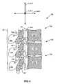
- FIG. 3illustrates an enlarged cross-sectional view of a vertebral foramen 15 within a vertebra.
- Vertebral foramen 15includes epidural space 27 and spinal cord 28 containing nerves 34 and CSF within dural sac 32 .
- a thickened/enlarged ligamentum flavum 26extends into vertebral foramen 15 .
- a safety zone 40is created between ligamentum flavum 26 and dural sac 32 .
- spinal cord 28comprises nerves 34 surrounded by CSF and is contained within dural sac 32 . Since more than 90% of the volume of dural sac 32 in the lumbar, region is filled by CSF, dural sac 32 is highly compressible. Thus, even when stenosis is causing compression of spinal cord 28 , in most cases it is possible to temporarily compress spinal cord 28 further. Thus, according to preferred embodiments, dural sac 32 is further compressed in the region of interest by injecting a fluid into epidural space 27 to create safety zone 40 .
- safety zone 40The presence of the injected fluid comprising safety zone 40 gently applies an additional compressive force to the outer surface of dural sac 32 so that at least a portion of the CSF within dural sac 32 is forced out of dural sac 32 in the region of interest, resulting in safety zone 40 between dural sac 32 and ligamentum flavum 26 .
- dural sac 32is compressed by injecting a standard radio-opaque non-ionic myelographic contrast medium or other imagable or non-imagable medium into epidural space 27 in the region of interest. This is preferably accomplished with a percutaneous injection. Sufficient injectable fluid is preferably injected to displace the CSF out of the region of interest and compress dural sac 32 to at least a desired degree. The injected medium is preferably substantially contained within the confines of epidural space 27 extending to the margins of the dural sac 32 .
- the epidural spaceis substantially watertight and the fatty tissues and vascularization in epidural space 27 , combined with the viscous properties of the preferred fluids, serve to substantially maintain the injected medium in the desired region of interest.
- This novel method for protecting spinal cord 28 columnmay be referred to hereinafter as “contrast-guided dural protection.”
- a tool 100may be inserted into the ligamentum flavum 26 , as will be described in more detail below.
- Tool 100may comprise any suitable device, tool or instrument for relieving stenosis caused by the thickened/enlarged ligamentum flavum 26 including without limitation, embodiments of tissue excision devices and tissue retraction devices described in more detail below.
- tool 100is inserted and positioned in the ligamentum flavum 26 on the same side (ipsilateral) of median plane 210 as tool 100 percutaneously accesses the body, such that tool 100 does not cross median plane 210 .
- tool 100is positioned in the ligamentum flavum 26 on the opposite side of median plane 210 as tool 100 percutaneously accesses the body, such that tool 100 crosses median plane 210 .
- the presence of safety zone 40reduces the likelihood that dural sac 32 will be damaged, even if the tool breaks through the anterior surface of ligamentum flavum 26 .
- Imaging windowse.g., a fluoroscopic window of access—FWA
- FWAfluoroscopic window of access
- an imaging windowmay be employed to aid in insertion of tool 100 into ligamentum flavum 26 as shown in FIG. 4A .
- Preferable imaging windows/viewsare described in more detail below.
- the spinecan be imaged using any suitable technology, including without limitation, 2D fluoroscopy, 3D fluoroscopy, CT, MRI, ultrasound or with direct visualization with fiber optic or microsurgical techniques. Stereotactic or computerized image fusion techniques are also suitable. Fluoroscopy is currently particularly well-suited to the techniques disclosed herein. Fluoroscopic equipment is safe and easy to use, readily available in most medical facilities, relatively inexpensive. In a typical procedure, using direct biplane fluoroscopic guidance and local anesthesia, epidural space 27 is accessed for injection of contrast media adjacent to the surgical site.
- safety zone 40 created by the present contrast-guided dural compression techniquescan reduce the risk of damage to dural sac 32 and spinal cord 28 during minimally invasive decompression procedures to remove or displace portions of ligamentum flavum 26 and/or laminae 16 in order to treat spinal stenosis.
- the injected mediumcan be provided as a re-absorbable water-soluble gel, so as to better localize safety zone 40 at the site of surgery and reduce leakage of this protective layer from the vertebral/spinal canal.
- An injectable gelis a significant improvement on prior epidural injection techniques.
- the gelis preferably substantially more viscid than conventional contrast media and the relatively viscid and/or viscous gel preferably tends to remain localized at the desired site of treatment as it does not spread as much as standard liquid contrast media that are used in epidurography. This may result in more uniform compression of dural sac 32 and less leakage of contrast out of the vertebral/spinal canal.
- preferred embodiments of the gelare re-absorbed more slowly than conventional contrast media, allowing for better visualization during the course of the surgical procedure.
- a contrast agentcan be included in the gel itself, so that the entire gel mass is imagable.
- an amount of contrastcan be injected first, followed by the desired amount of gel, or an amount of gel can be injected first, followed by the desired amount of contrast.
- the contrast agentis captured on the surface of the expanding gel mass, so that the periphery of the mass is imagable.
- any standard hydrophilic-lipophilic block copolymer (Pluronic) gelsuch as are known in the art would be suitable and other gels may be used as the injectable medium.
- the gelpreferably has an inert base.
- the gel materialis liquid at ambient temperatures and can be injected through a small bore, such as a 27 gauge needle.
- the gelthen preferably becomes viscous when warmed to body temperature after being injected.
- the viscosity of the gelcan be adjusted through the specifics of the preparation.
- the gel or other fluidis preferably sufficiently viscid or viscous at body temperature to compress and protect dural sac 32 in the manner described above and to remain sufficiently present in the region of interest for at least about 30 minutes.
- the injected gelattains a viscosity that is two, three, six or even ten times that of the fluids that are typically used for epidurograms.
- the injected mediumundergoes a reversible change in viscosity when warmed to body temperature so that it can be injected as a low-viscosity fluid, thicken upon injection into the patient, and be returned to its low-viscosity state by cooling.
- the injected mediumis injected as desired and thickens upon warming, but can be removed by contacting it with a heat removal device, such as an aspirator that has been provided with a cooled tip.
- a heat removal devicesuch as an aspirator that has been provided with a cooled tip.
- a suitable contrast medium having the desired propertiesis Omnipaque® 240 available from Nycomed, N.Y., which is a commercially available non-ionic iodinated myelographic contrast medium.
- Other suitable injectable mediawill be known to those skilled in the art. Because of the proximity to spinal cord 28 and spinal nerves 34 , it is preferred not to use ionic media in the injectable medium The preferred compositions are reabsorbed relatively rapidly after the procedure. Thus any residual gel compression on dural sac 32 after the minimally invasive ligament decompression procedure dissipates relatively quickly. For example, in preferred embodiments, the gel would have sufficient viscosity to compress dural sac 32 for thirty minutes, and sufficient degradability to be substantially reabsorbed within approximately two hours.
- the injected contrast mediumfurther may further include one or more bioactive agents.
- medicationssuch as those used in epidural steroid injection (e.g. Depo Medrol®, Celestone Soluspan®) may be added to the epidural gel to speed healing and reduce inflammation, scarring and adhesions.
- the gelpreferably releases the steroid medication slowly and prolongs the anti-inflammatory effect, which can be extremely advantageous.
- Local anesthetic agentsmay also be added to the gel. This prolongs the duration of action of local anesthetic agents in the epidural space to prolong pain relief during epidural anesthesia.
- the gelmay be formulated to slow the reabsorption of the gel.
- the present gelsmay also be used for epidural steroid injection and perineural blocks for management of acute and chronic spinal pain.
- Thrombin or other haemostatic agentscan be added if desired, so as to reduce the risk of bleeding.
- the gelmay also be used as a substitute for a blood patch if a CSF leak occurs.
- the gelmay also be used as an alternative method to treat lumbar puncture complications such as post-lumbar puncture CSF leak or other causes of intracranial hypotension.
- the gelmay be used to patch postoperative CSF leaks or dural tears. If the dural sac were inadvertently torn or cut, then gel could immediately serve to seal the site and prevent leakage of the cerebral spinal fluid.
- a variety of suitable techniquesmay be employed to reduce the size of the thickened/enlarged ligamentum flavum 26 , thereby decompressing spinal cord 28 as well as blood vessels contained within the epidural space 27 .
- suitable decompression techniquesinclude without limitation, removal of tissue from ligamentum flavum 26 , laminectomy, laminotomy, and retraction and anchoring of ligamentum flavum 26 .
- all or a portion of ligamentum flavum 26is excised using a tissue excision tool (e.g., tool 100 ).
- a tissue excision toole.g., tool 100 .
- Accessing ligamentum flavum 26 with a tool 100 to remove portions of ligamentum flavum 26can present significant challenges For instance, in some conventional approaches to correct stenosis caused by an enlarged ligamentum flavum, an incision is made in the back of the patient and then the muscles and supporting structures of the vertebral column (spine) are stripped away, exposing the posterior aspect of the vertebral column. Subsequently, the thickened ligamentum flavum is exposed by removal of a portion of vertebral arch 14 , often at lamina 16 , which encloses the anterior portion of the spinal canal (laminectomy). The thickened ligamentum flavum ligament can then be excised by sharp dissection with a scalpel or punching instruments.
- some minimally invasive ligament decompression proceduresaccess ligamentum flavum 26 percutaneously by boring a hole through the vertebral arch 14 of vertebra 10 , often through a lamina 16 .
- a cannula and/or tool 100may be passed through the bore and/or anchored to the bore to access ligamentum flavum 26 for excisions
- such a minimally invasive ligament decompression approachis minimally invasive and reduces recovery time, such an approach requires the additional step of boring a hole in the posterior of the vertebra 10 of interest.
- FIG. 6is a partial cross-sectional lateral view of a segment of a vertebral column 80 .
- the segment of vertebral column 80 illustrated in FIG. 6includes three vertebrae 10 a , 10 b , and 10 c .
- Each vertebra 10 a , 10 b , 10 cincludes a vertebral body 12 a , 12 b , 12 c , that supports a vertebral arch 14 a , 14 b , 14 c , respectively.
- Vertical body 12 a , 12 b , 12 cis anterior to vertebral arch 14 a , 14 b , 14 c , respectively.
- the succession of vertebral foramen 15 a , 15 b , 15 c in adjacent vertebrae 10 a , 10 b , 10 cdefine vertebral canal 81 (spinal canal) that runs along the length of vertebral column 80 .
- Vertebral canal 81contains the spinal cord (not shown in FIG. 6 ).
- each vertebral arch 14 a , 14 b , 14 cincludes two pedicles 24 a , 24 b , 24 c , which project posteriorly to meet two lamina 16 a , 16 b , 16 c , respectively. It is to be understood that in this view, one pedicle has been removed from each vertebra 10 a , 10 b , 10 c and only the cross-section of one lamina 16 a , 16 b , 16 c is visible The two lamina 16 a , 16 b , 16 c meet posteriomedially to form the spinous process 18 a , 18 b , 18 c , respectively.
- ligamentum flavum 26(shown in cross-section).
- the relatively elastic ligamentum flavum 26extends almost vertically from superior lamina to inferior lamina of adjacent vertebrae
- ligamentum flavum 26originates on the inferior surface of the laminae of the superior vertebrae and connects to the superior surface of the laminae of the inferior vertebrae.
- ligamentum flavum 26originates on the inferior surface of lamina 16 a of superior vertebra 10 a and connects to the superior surface of lamina 16 b of the inferior vertebra 10 b .
- ligamentum flavum 26spans an interlaminar space 82 (i.e., space between laminae of adjacent vertebrae).
- Interlaminar space 82is generally the space between laminae of adjacent vertebrae in spinal column 80 .
- each lamina 16 a , 16 b , 16 ccomprises a relatively broad flat plate of bone that extends posteromedially and slightly inferiorly from pedicles 24 a , 24 b , 24 c , respectively.
- the lamina 16 a , 16 b , 16 coverlap like roofing shingles, with each lamina substantially parallel to and at least partially overlapping the adjacent inferior lamina.
- the adjacent substantially parallel laminaeare separated by the intervening ligamentum flavum 26 and interlaminar space 82 .
- lamina 16 ais substantially parallel to and partially overlaps adjacent inferior lamina 16 b and is separated from lamina 16 b by ligamentum flavum 26 and interlaminar space 82 .
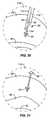
- FIG. 7illustrates vertebral column 80 as it may be oriented with the anterior side positioned down and posterior back surface 85 positioned upward, as may be encountered during a spinal procedure or surgery.
- ligamentum flavum 26is thickened/enlarged, resulting in spinal stenosis.
- the anterior portions of enlarged ligamentum flavum 26are extending into spinal canal 81 , potentially exerting compressive forces on the spinal cord (not shown) that resides within spinal canal 81 .
- portions of ligamentum flavum 26may be excised.
- the innate structure of vertebral column 80 and each vertebramay present significant imaging challenges. For instance, lateral imaging windows/views of ligamentum flavum 26 substantially in the direction of the z-axis may be obscured by the various processes of the vertebrae (e.g., transverse processes, superior articular processes, inferior articular processes), the laminae of each vertebra, etc.
- anterior-posterior (A-P) imaging windows/views of ligamentum flavum 26 substantially in the direction of the x-axismay also be obscured by the laminae.
- the posterior edges of parallel laminaeoverlap and obscure ligamentum flavum 26 and interlaminar space 82 , particularly the anterior portions of ligamentum flavum 26 and interlaminar space 82 closest to spinal canal 81 .
- an imaging window/view in a plane substantially parallel to the X-Y planeat an angle .theta.
- interlaminar space 82 and ligamentum flavum 26may be viewed without significant obstruction from neighboring laminae.
- imaging windows/views generally aligned with arrow 83FIG. 7 ) allow a more direct view of interlaminar space 82 and ligamentum flavum 26 from the posterior back surface with minimal obstruction by the vertebrae, laminae in particular.
- the long axis of the substantially parallel laminaee.g., laminae 16 a , 16 , b , 16 c
- interlaminar spacese.g, interlaminar spaces 82
- the imaging meanse.g., x-ray beam, fluoroscopy tube, etc.
- the imaging meansis positioned generally in the direction represented by arrow 83 , where ⁇ is substantially between 60 and 75 degrees relative to the anterior back surface 85 .
- the imaging meansis positioned substantially parallel to the surface of the laminae.
- the resulting imaging window/viewpermits a clearer, more direct, less obstructed view of interlaminar space 82 and ligamentum flavum 26 from the general posterior back surface 85 .
- the caudal-cranial posterior viewpermits a relatively clear view of interlaminar space 82 and ligamentum flavum 26 in directions generally along the y-axis and z-axis.
- the caudal-cranial posterior viewby itself may not provide a clear imaging window/view of interlaminar space 82 and ligamentum flavum 26 in directions generally along the x-axis.
- the caudal-cranial posterior viewby itself may not provide a clear imaging window/view that can be used to accurately determine the posterior-anterior depth, measured generally along the x-axis, of a device across the ligamentum flavum 26 .
- an additional imaging window/viewtermed “caudal-cranial posterior-lateral view” hereinafter, is employed to provide a clearer, unobstructed view of interlaminar space 82 and ligamentum flavum 26 in directions generally along the y-axis and z-axis.
- the caudal-cranial posterior-lateral viewis generated by orienting an imaging means generally at an angle ⁇ relative to outer surface of the patient and also angling such imaging means laterally in an oblique orientation, revealing a partial lateral view of interlaminar space 82 occupied by ligamentum flavum 26 on the anterior side of the lamina and posterior to the underlying dural sac (not shown) and spinal cord (not shown).
- caudal-cranial posterior view and the caudal-cranial posterior-lateral viewsBy employing at least one of the caudal-cranial posterior view and the caudal-cranial posterior-lateral views, relatively clear imaging windows/views of the interlaminar space 82 and ligamentum flavum 26 in directions along the x-, y-, and z-axis may be achieved.
- FIG. 8illustrates vertebral column 80 and an instrument 101 .
- instrument 101is employed to percutaneously access interlaminar space 82 and ligamentum flavum 26 .
- Instrument 101may be any suitable device necessary to perform the minimally invasive ligament decompression procedures described herein including without limitation, a cannula, a tissue excision tool, or combinations thereof. Tissue excision tools are described in more detail below.
- instrument 101can be employed to penetrate the skin and soft tissue in the posterior back surface 85 of the patient.
- the skin entry point for instrument 101is between 5 and 10 cm inferior (caudal to) the posterior surface of the interlaminar space 82 of interest.
- instrument 101may be inserted into the patient's back about 5 to 10 cm inferior to posterior surface 84 of interlaminar space 82 .
- instrument 101is preferably initially inserted into the posterior tissue and musculature of the patient generally parallel to the longitudinal axis of spinal column 80 .
- the angle .beta. between the posterior back surface 85 and tool 100is between 0 and 10 degrees when tool 100 is initially inserted.
- instrument 101is preferably inserted into the posterior tissue and musculature of the patient on the same side (ipsilateral) of the median plane as the area of interest (e.g., the targeted portion of ligamentum flavum 26 ), as best seen in FIG. 4 .
- instrument 101then may be oriented 5 to 90 degrees relative to the posterior back surface 85 in order to create a trajectory across ligamentum flavum 26 in the area of interest. It is to be understood that once instrument 101 is inserted into the patient's posterior back surface 85 , the ends of instrument 101 are free to pivot about the insertion location in posterior back surface 85 in the general direction of the y-axis and the z-axis, and may be advanced posteriorly or anteriorly generally in the direction of the x-axis.
- instrument 101can be positioned to provide a pathway across interlaminar space 82 in the area of interest, generally towards the anterior surface of the lamina superior to the area of interest. For example, if interlaminar space 82 between lamina 16 a and lamina 16 b is the area of interest, instrument 101 is positioned to provide a trajectory that will allow a cutting instrument to be inserted across interlaminar space 82 between lamina 16 a and lamina 16 b towards the anterior surface of lamina 16 a (superior lamina).
- instrument 101By switching between the caudal-cranial posterior view and the caudal-cranial posterior-lateral view, or by viewing both the caudal-cranial posterior view and the caudal-cranial posterior-lateral view at the same time, instrument 101 , or an excision tool passing through instrument 101 (e.g., tool 100 ), can be advanced and inserted into ligamentum flavum 26 in the area of interest with more certainty than has heretofore been present. Once instrument 101 , or an excision tool passing therethrough, is inserted into ligamentum flavum 26 , portions of ligamentum flavum 26 may be excised so as to relieve pressure on the spinal nerves.
- an excision tool passing through instrument 101e.g., tool 100
- resectioncan be performed generally from posterior to anterior across interlaminar space 82 and then laterally along the anterior portion of ligamentum flavum 26 if desired.
- the actual depth of the instrument tip in the general direction of the x-axismay be adjusted with guidance from the caudal-cranial posterior-lateral view and appropriate retraction/advancement of instrument 101 and appropriate adjustment of instrument 101 between 5 and 90 degrees relative to the posterior back surface 85 .
- ligamentum flavum 26can be accessed, and portions thereof removed via the interlaminar space on the same lateral side (ipsilateral) of median plane 210 as the entry point for the cannula (e.g., instrument 101 ) and cutting instrument (e.g., tool 100 ).
- This approachmay sometimes hereinafter be referred to as an Ipsilateral Approach MILD Procedure (ILAMP).
- ILAMPIpsilateral Approach MILD Procedure
- an excision tool 100is shown schematically within ligamentum flavum 26 .
- tool 100has accessed ligamentum flavum 26 according to the ILAMP method previously described.
- tool 100is positioned to excise portions of ligamentum flavum 26 on the same lateral side of median plane 210 as tool 100 is inserted.
- tool 100is inserted into the body on the right side of median plane 210 and enters ligamentum flavum 26 on the right side of median plane 210 to excise portions of ligamentum flavum 26 on the tight side of median plane 210 .
- tool 100does not cross median plane 210 .
- FIG. 5illustrates an embodiment of an alternative minimally invasive ligament decompression method in which tool 100 is positioned to excise portions of ligamentum flavum 26 on the opposite lateral side of median plane 210 as tool 100 is inserted. More specifically, tool 100 is inserted into the body on the rights side of median plane 210 and enters ligamentum flavum 26 on the right side of median plane 210 , to excise portions of ligamentum flavum 26 on the left side of median plane 210 . In FIG. 5 , tool 100 crosses median plane 210 .
- Embodiments of the present tissue excision devices and techniquescan take several forms.
- the distal ends of the toolsare described in detail.
- the construction of the proximal ends of the tools, and the means by which the various components disclosed herein are assembled and actuated,will be known and understood by those skilled in the art.
- device 100may be a coaxial excision system 50 with a sharpened or blunt tip that is placed obliquely into the thickened ligamentum flavum 26 posterior to safety zone 40 under fluoroscopic guidance.
- Excision system 50is preferably manufactured from stainless steel, titanium or other suitable durable biocompatible material.
- an outer needle or cannula 51has an opening or aperture 52 on one side that is closed during insertion by an inner occluding member 54 . Aperture 52 is readily visible under imaging guidance. Once needle 51 is positioned in the ligamentum flavum or other tissue removal site, inner occluding member 54 is removed or retracted so that it no longer closes aperture 52 ( FIG. 10 ).
- Aperture 52is preferably oriented away from the epidural space so as to further protect the underlying structures from injury during the surgical procedure. If it was not already present in the tool, a tissue-engaging means 56 is inserted through outer needle 51 to aperture 52 so that it contacts adjacent tissue, e.g. the ligamentum flavum, via aperture 52 .
- Tissue-engaging means 56may be a needle, hook, blade, tooth or the like, and preferably has at least one flexible barb or hook 58 attached to its shaft.
- the barb 58 or barbsmay extend around approximately 120 degrees of the circumference of the shaft.
- Barbs 58are preferably directed towards the proximal end of the tool.
- barbs 58allow it to engage a segment of tissue.
- the tissue sample engaged by needle 56may be generally cylindrical or approximately hemispherical.
- occluding means 54also functions as a cutting means in this embodiment.
- a cylindrical outer cutting element 60may extended over outer needle 51 and used in place of occluding member 54 to excise the tissue sample.
- tissue-engaging needle 56can be pulled back through outer needle 51 so that the segment of tissue can be retrieved and removed from the barbs ( FIG. 12 ). The process or engaging and resecting tissue may be repeated ( FIG. 13 ) until the canal is adequately decompressed.
- a tissue-engaging hook 64can be used in place of needle 56 and an outer cutting member 60 can be used in place of inner occluding member 54 .
- Hook 64may comprise a length of wire that has been bent through at least about 270°, more preferably though 315°, and still more preferably through about 405°.
- hook 64may comprise Nitinol®, or any other resilient metal that can withstand repeated elastic deflections.
- hook 64includes at least one barb 58 at its distal end.
- hook 64is pre-configured in a curvilinear shape and is retained within tool 100 by outer cutting member 60 .
- hook 64When cutting member 60 is retracted, the curved shape of hook 64 urges its outer end to extend outward through aperture 52 . If desired, hook 64 can be advanced toward the distal end of tool 100 , causing it to extend farther into the surrounding tissue.
- hook 64is provided with a camming surface 66 .
- Camming surface 66bears on the edge of opening 52 as hook 64 is advance or retracted and thereby facilitates retraction and retention of hook 64 as it is retracted into the tool. In these embodiments, hook 64 may not extend through aperture 52 until it has been advanced sufficiently for camming surface 66 to clear the edge of the opening. Hook 64 may alternatively be used in conjunction with an inner occluding member 54 in the manner described above. As above, hook 64 can be used to retrieve the engaged tissue from the distal end of the tool.
- the tissue-engaging meansmay comprise a hook or tooth or the like that engages tissue via aperture 52 by being rotated about the tool axis.
- the tissue-engaging meanscould comprise a partial cylinder that is received in outer cannula 51 and has a serrated side edge. Such a device can be rotated via a connection with the tool handle or other proximal device. As the serrated edge traverses aperture 52 tissue protruding into the tool via the aperture is engaged by the edge, whereupon it can be resected and retrieved in the manner disclosed herein.
- the working tip of tool 100remains within the ligamentum flavum and does not penetrate the safety zone 40 . Nonetheless, safety zone 40 is provided so that even an inadvertent penetration of the tool into the epidural space will not result in damage to the dural sac.
- tissue-removal devicesuch as that described below is preferably used to remove the tissue from the retrieval device between each excision.
- Each piece of tissuemay be removed from barbs 58 by pushing tissue-engaging means 56 through an opening that is large enough to allow passage of the flexible barbs and supporting needle but smaller than the diameter of the excised tissue mass. This pushes the tissue up onto the shaft, where it can be removed with a slicing blade or the like or by sliding the tissue over the proximal end of the needle.
- needle 56can be removed and re-inserted into the tool for external, manual tissue removal.
- approximately 8-10 cores or segments of tissuewill be excised and pushed up the shaft towards the hub during the course of the procedure.
- a small bladecan be used to split the tissue segment and thereby ease removal of the segment from the device.
- a blade for this purposecan be placed on the shaft of needle 56 proximal to the barbs.
- the tissue removal devicemay include a scraper 120 that includes a keyhole slot having a wide end 122 and a narrow end 124 .
- the tissue-engaging device with a mass of excised tissue 110 thereoncan be retracted (pulled toward the proximal end of the tool) through wide end 122 of the slot and then re-inserted (pushed toward the distal end of the tool) through narrow end 124 of the slot.
- Narrow end 124is large enough to allow passage of the barbed needle, but small enough to remove the tissue mass as the needle passes through.
- the removed tissuecan exit the tool through an opening 113 in the tool body.
- the tissue removal devicemay be constructed such that tissue is removed from the tissue-engaging device by retracting the tissue-engaging device through narrow end 124 of the slot.
- narrow end 124is large enough to allow passage of the shaft of the tissue-engaging device, but small enough to remove the tissue mass as the needle passes through.
- the tissue-engaging deviceis constructed of a tough material, the barbs or the like will cut through the tissue and/or deform and release the tissue.
- the removed tissuecan exit the tool through an opening 113 in the tool body.
- an alternative mechanism for removing the tissue segment from needle 56includes an adjustable aperture in a disc. After the tissue-bearing needle is pulled back through the aperture, the aperture is partially closed. Needle 56 and flexible hooks 58 then can pass through the partially closed aperture but the larger cylinder of tissue cannot. Thus the tissue segment is pushed back onto the shaft. The tissue segment can either be pulled off the proximal end of the shaft or cut off of it. A small blade may be placed just proximal to the barbs to help cut the tissue segment off the shaft.
- the variable aperturecan formed by any suitable construction, including a pair of metal plates with matching edges that each define one half of a central opening. The two pieces may be held apart by springs. The aperture may be closed by pushing the two edges together. In other embodiments, this process can be mechanically automated by using a disc or plate with an opening that is adjustable by a variety of known techniques, including a slit screw assembly or flexible gaskets.
- embodiments of the grasping mechanisminclude but are not limited to: needles with flexible barbs, needles with rigid barbs, corkscrew-shaped needles, and/or retaining wires.
- the corkscrew-shaped needle shown in FIG. 24works by screwing into the ligamentum flavum in the manner that a corkscrew is inserted in a cork. After the screw engages a segment of tissue, outer cutting element 60 slides over the needle, cutting a segment of tissue in a manner similar to that of the previous embodiment. In some embodiments, the cutting element can be rotated as it cuts.
- cannulated scalpel 71houses a grasping device 70 that includes at least one pair of arcuate, closable arms 72 .
- Closable arms 72may be constructed in any suitable manner.
- One technique for creating closable armsis to provide a slotted sleeve 74 , as shown.
- Slotted member 74preferably comprises an elongate body 75 with at least one slot 76 that extends through its thickness but does not extend to either end of the body. Slot 76 is preferably parallel to the longitudinal axis of the sleeve.
- a strip 77is defined, with strips 77 being joined at each end of sleeve 74 .
- each strip 77be relatively small. In some embodiments, it may be desirable to construct slotted member 74 from a portion of a hollow tube or from a rectangular piece that has been curved around a longitudinal axis. The inner edge of each strip that lies along slot 76 forms an opposing edge 78 . The width of the piece is the total of the width of strips 77 and slot 76 .
- each strip 77Advancing one end of sleeve 74 toward the other end of sleeve 74 causes each strip 77 to buckle or bend. If strips 77 are prevented from buckling inward or if they are predisposed to bend in the desired direction, they will bend outward, thereby forming arcuate arms 72 , which extend through aperture 52 of cannulated scalpel 71 , as shown in FIG. 29 . As they move away from the axis of body 75 , arms 72 move apart in a direction normal to the axis of body 75 . Likewise, moving the ends of sleeve 74 apart causes arms 72 to straighten and to move together and inward toward the axis of the device, as shown in FIG. 27 . As the arms straighten, opposing edges 78 close and a segment of tissue can be captured between them. Tissue within the grasping device may then be resected or anchored via the other mechanisms described herein.
- Closable arms 72may include on their opposing edges 78 ridges, teeth, or other means to facilitate grasping of the tissue. In other embodiments, edges 78 may be sharpened, so as to excise a segment of tissue as they close. In these embodiments, closable arms 72 may also be used in conjunction with a hook, barbed needle, pincers or the like, which can in turn be used to retrieve the excised segment from the device.
- the tissuecan be excised using a blade such as cutting element 60 above.
- the excised tissuecan be removed from the inside of needle 51 using a tissue-engaging hook 64 or other suitable means.
- the process of extending and closing arms 72 , excising the tissue, and removing it from the devicecan be repeated until a desired amount of tissue has been removed.
- this cyclecan be repeated without repositioning the device in the tissue.
- the toolcan be rotated or repositioned as desired between excisions. It is possible to rotate or reposition the tool during an excision, but it is expected that this will not generally be preferred. Furthermore, it is expected that the steps of tissue excision and removal can be accomplished without breaching the surface of the ligament, i.e. without any part of the device entering the safety zone created by the injected fluid. Nonetheless, should the tool leave the working zone, the safety zone will reduce the risk of injury to the dural sac.
- the spinal canalmay also be enlarged by retracting the ligamentum flavum, either with or without concurrent resection.
- Retractionis preferably but not necessarily performed after dural compression has been used to provide a safety zone.
- the dural compression techniques described abovehave the effect of pressing the ligamentum flavum back out of the spinal canal and thereby making it easier to apply a restraining means thereto.
- a retraction device 90as shown in FIG. 30 is used to retract and compress the thickened soft tissues around the posterior aspect of the spinal canal, thereby increasing the available space for the dural sac and nerves.
- retraction device 90is a double-headed anchor that includes at least one distal retractable tissue-engaging member 91 and at least one proximal tissue-engaging member 92 , each of which are supported on a body 94 .
- Retraction device 90is preferably constructed from an implantable, non-biodegradable material, such as titanium or stainless steel, but may alternatively be polymeric or any other suitable material.
- body 94is somewhat flexible.
- barbs 91 , 92may comprise hooks, arms, teeth, clamps, or any other device capable of selectively engaging adjacent tissue. Barbs 91 , 92 may have any configuration that allows them to engage the ligamentum flavum and/or surrounding tissue. Similarly, barbs 91 , 92 may be covered, sheathed, pivotable, retractable, or otherwise able to be extended from a first position in which they do not engage adjacent tissue to a second position in which they can engage adjacent tissue.
- FIG. 30shows schematically the distal and proximal retractable arms 91 , 92 of a preferred ligament anchor 90 .
- the proximal end of the anchorpreferably includes a threaded connector 96 or other releasable mechanism that attaches to a support rod 100 .
- Ligament anchor 90may be attached to a support shaft 112 and sheathed in a guide housing 114 .
- the distal and proximal barbs 91 , 92are prevented by guide housing 114 from engaging surrounding tissue.
- Housing 114is preferably a metal or durable plastic guide housing.
- the distal end of the deviceis preferably positioned in the ligamentum flavum under fluoroscopic guidance. If desired, an accessway through the lamina may be provided using an anchored cannula or the like.
- the deviceis held in position by support shaft 112 .
- Distal barbs 91are unsheathed and optionally expanded by pulling back guide housing 114 , as shown in FIG. 30 .
- Distal barbs 91are secured in the ligamentum flavum by pulling back on the support shaft 112 . With barbs 91 engaging the tissue, the ligamentum flavum is retracted posteriorly by pulling back on support shaft 112 .
- proximal barbs 92are uncovered and expanded by retracting guide housing 114 , as shown in FIG. 31 .
- Barbs 92are preferably positioned in the soft tissues 116 in the para-spinal region so that the device is firmly anchored behind the posterior elements of the spinal canal.
- support shaft 112may be detached from body 94 as shown in FIG. 31 .
- the posterior margin 95 of the ligamentum flavumcan be held in a retracted position, thereby expanding the canal. The procedure can then be repeated on adjacent portions of the ligamentum flavum until it is sufficiently retracted.
- the proximal end of ligament anchor 90may be adapted to engage the lamina. This may be accomplished by having the arm posterior to the lamina or by using the laminotomy and suturing the device to the lamina there. A knotted or knotless system or a suture plate can be used.
- a second embodiment of the present methoduses a plurality of retraction devices 90 .
- the retraction deviceis inserted through one lamina in an oblique fashion, paralleling the opposite lamina. After the distal anchor is deployed, the retraction device is pulled back and across the ligamentum flavum, thereby decompressing the opposite lateral recess of the spinal canal. This is repeated on the opposite side.
- This same devicecan also be deployed with a direct approach to the lateral recess with a curved guide housing.
- retraction device 90is described above as a double-headed anchor, it will be understood that other devices can be used.
- sutures, barbed sutures, staples or the likecan be used to fasten the ligament in a retracted position that reduces stenosis.
- a dural sac cross-sectional area less than 100 mm 2 or an anteroposterior (A-P) dimension of the canal of less than 10-12 mm in an average maleis typically considered relative spinal stenosis.
- a dural sac cross-sectional area less than 85 mm.sup.2 in an average maleis considered severe spinal stenosis.
- the present devices and techniquesare anticipated to cause an increase in canal area of 25 mm 2 per anchor or 50 mm 2 total.
- the cross-sectional area of the dural saccan be increased by 10 mm 2 , and in some instances by as much as 20 mm 2 or even 30 mm 2
- the present inventioncan result in an increase of the anteroposterior dimension of the canal by 1 to 2 mm and in some instances by as much as 4 or 6 mm.
- the actual amount by which the cross-sectional area of the dural sac and/or the anteroposterior dimension of the canal are increasedwill depend on the size and age of the patient and the degree of stenosis and can be adjusted by the degree of retraction of the ligament.
- a mechanical devicesuch as a balloon or mechanical shield can also be used to create a protective guard or barrier between the borders of the epidural space and the adjacent structures.
- a durable expandable deviceis attached to the outside of the percutaneous laminectomy device, preferably on the side opposite the cutting aperture. The cutting device is inserted into the ligamentum flavum with the expandable device deflated. With the aperture directed away from the spinal canal, the expandable device is gently expanded via mechanical means or inflated with air or another sterile fluid, such as saline solution, via a lumen that may be within of, adjacent to the body of the device. This pushes the adjacent vital structures clear from the cutting aperture of the device and simultaneously presses the cutting aperture into the ligament.
- the grasping and cutting needlescan then be deployed and operated as desired.
- the balloondoes not interfere with tissue excision because it is located on the side opposite the cutting aperture.
- the cutting needlemay be hemispherical (semi-tubular) in shape with either a straight cutting or a sawing/reciprocating blade or may be sized to be placed within the outer housing that separates the balloon from the cutting aperture.
- a self-expanding metal meshis positioned percutaneously in the epidural spaces.
- a guide catheteris placed in the epidural space at the site of the intended surgical procedure.
- the meshis preferably compressed within a guide catheter.
- the meshexpands in the epidural space, protecting and displacing the adjacent dural sheath.
- the meshmay be configured to have an expanded shape that generally corresponds to the shape of the desired safety zone within the spinal canal.
- the meshis pulled back into the guide sheath and the assembly removed.
- the meshis deformable and compresses as it is pulled back into the guide catheter, in a manner similar to a self-expanding mesh stent. While there are commercially available self-expanding stents approved and in use in other applications, using a self-expandable mesh configured to expand within the epidural space so as to protect and displace the dural sac is novel.
- the ILAMP methods, techniques, and devices described hereinallow spinal decompression to be performed percutaneously, avoiding the pain, lengthy recovery time, and risk associated with open surgery.
- the ILAMP methods, techniques, and devices described hereinpermit clearer, less obstructed imaging views of the interlaminar spaces and ligamentum flavum between the laminae in the areas of interest. Such improved imaging views offer the potential for enhanced accuracy and safety in the placement of tools within the ligamentum flavum proximal the epidural space and spinal cord.
- the ILAMP methods, techniques, and devices described hereinpermit the excision of portions of the ligaments flavum on the same lateral side of the median plane as that into which instruments and tools for the procedure are inserted.
- the present devices and techniquesoffer reduced risk of spinal cord damage.
- decompression of the spinal canal in the manner described hereinwill result in improved blood flow to the neural elements by reducing the extrinsic pressure on the spinal vasculature.
- spinal decompression performed according to the present inventionwill be preferable to decompression operations performed using currently known techniques.
Landscapes
- Health & Medical Sciences (AREA)
- Life Sciences & Earth Sciences (AREA)
- Surgery (AREA)
- Engineering & Computer Science (AREA)
- Veterinary Medicine (AREA)
- Biomedical Technology (AREA)
- Heart & Thoracic Surgery (AREA)
- Medical Informatics (AREA)
- Animal Behavior & Ethology (AREA)
- General Health & Medical Sciences (AREA)
- Public Health (AREA)
- Molecular Biology (AREA)
- Nuclear Medicine, Radiotherapy & Molecular Imaging (AREA)
- Vascular Medicine (AREA)
- Orthopedic Medicine & Surgery (AREA)
- Biophysics (AREA)
- High Energy & Nuclear Physics (AREA)
- Optics & Photonics (AREA)
- Pathology (AREA)
- Radiology & Medical Imaging (AREA)
- Physics & Mathematics (AREA)
- Anesthesiology (AREA)
- Hematology (AREA)
- Surgical Instruments (AREA)
- Infusion, Injection, And Reservoir Apparatuses (AREA)
- Prostheses (AREA)
Abstract
Description
Claims (32)
Priority Applications (2)
| Application Number | Priority Date | Filing Date | Title |
|---|---|---|---|
| US12/188,360US8608762B2 (en) | 2006-05-09 | 2008-08-08 | Translaminar approach to minimally invasive ligament decompression procedure |
| US14/032,853US8734477B2 (en) | 2006-05-09 | 2013-09-20 | Translaminar approach to minimally invasive ligament decompression procedure |
Applications Claiming Priority (2)
| Application Number | Priority Date | Filing Date | Title |
|---|---|---|---|
| US11/382,349US7942830B2 (en) | 2006-05-09 | 2006-05-09 | Ipsilateral approach to minimally invasive ligament decompression procedure |
| US12/188,360US8608762B2 (en) | 2006-05-09 | 2008-08-08 | Translaminar approach to minimally invasive ligament decompression procedure |
Related Parent Applications (1)
| Application Number | Title | Priority Date | Filing Date |
|---|---|---|---|
| US11/382,349ContinuationUS7942830B2 (en) | 2006-05-09 | 2006-05-09 | Ipsilateral approach to minimally invasive ligament decompression procedure |
Related Child Applications (1)
| Application Number | Title | Priority Date | Filing Date |
|---|---|---|---|
| US14/032,853ContinuationUS8734477B2 (en) | 2006-05-09 | 2013-09-20 | Translaminar approach to minimally invasive ligament decompression procedure |
Publications (2)
| Publication Number | Publication Date |
|---|---|
| US20090036936A1 US20090036936A1 (en) | 2009-02-05 |
| US8608762B2true US8608762B2 (en) | 2013-12-17 |
Family
ID=38694670
Family Applications (3)
| Application Number | Title | Priority Date | Filing Date |
|---|---|---|---|
| US11/382,349Active2028-07-30US7942830B2 (en) | 2006-05-09 | 2006-05-09 | Ipsilateral approach to minimally invasive ligament decompression procedure |
| US12/188,360Active2028-08-21US8608762B2 (en) | 2006-05-09 | 2008-08-08 | Translaminar approach to minimally invasive ligament decompression procedure |
| US14/032,853ActiveUS8734477B2 (en) | 2006-05-09 | 2013-09-20 | Translaminar approach to minimally invasive ligament decompression procedure |
Family Applications Before (1)
| Application Number | Title | Priority Date | Filing Date |
|---|---|---|---|
| US11/382,349Active2028-07-30US7942830B2 (en) | 2006-05-09 | 2006-05-09 | Ipsilateral approach to minimally invasive ligament decompression procedure |
Family Applications After (1)
| Application Number | Title | Priority Date | Filing Date |
|---|---|---|---|
| US14/032,853ActiveUS8734477B2 (en) | 2006-05-09 | 2013-09-20 | Translaminar approach to minimally invasive ligament decompression procedure |
Country Status (5)
| Country | Link |
|---|---|
| US (3) | US7942830B2 (en) |
| EP (1) | EP2029027A2 (en) |
| JP (1) | JP2009536565A (en) |
| CA (1) | CA2651118A1 (en) |
| WO (1) | WO2007134100A2 (en) |
Cited By (21)
| Publication number | Priority date | Publication date | Assignee | Title |
|---|---|---|---|---|
| US9314279B2 (en) | 2004-10-20 | 2016-04-19 | The Board Of Trustees Of The Leland Stanford Junior University | Systems and methods for posterior dynamic stabilization of the spine |
| US9393055B2 (en) | 2004-10-20 | 2016-07-19 | Vertiflex, Inc. | Spacer insertion instrument |
| US9532812B2 (en) | 2004-10-20 | 2017-01-03 | Vertiflex, Inc. | Interspinous spacer |
| US9572603B2 (en) | 2004-10-20 | 2017-02-21 | Vertiflex, Inc. | Interspinous spacer |
| US9675303B2 (en) | 2013-03-15 | 2017-06-13 | Vertiflex, Inc. | Visualization systems, instruments and methods of using the same in spinal decompression procedures |
| US9861398B2 (en) | 2004-10-20 | 2018-01-09 | Vertiflex, Inc. | Interspinous spacer |
| US9956011B2 (en) | 2004-10-20 | 2018-05-01 | Vertiflex, Inc. | Interspinous spacer |
| US10039576B2 (en) | 2004-10-20 | 2018-08-07 | The Board Of Trustees Of The Leland Stanford Junior University | Systems and methods for posterior dynamic stabilization of the spine |
| US10058358B2 (en) | 2004-10-20 | 2018-08-28 | The Board Of Trustees Of The Leland Stanford Junior University | Systems and methods for posterior dynamic stabilization of the spine |
| US10080587B2 (en) | 2004-10-20 | 2018-09-25 | Vertiflex, Inc. | Methods for treating a patient's spine |
| US10278744B2 (en) | 2004-10-20 | 2019-05-07 | The Board Of Trustees Of The Leland Stanford Junior University | Systems and methods for posterior dynamic stabilization of the spine |
| US10292738B2 (en) | 2004-10-20 | 2019-05-21 | The Board Of Trustees Of The Leland Stanford Junior University | Systems and methods for stabilizing the motion or adjusting the position of the spine |
| US10524772B2 (en) | 2014-05-07 | 2020-01-07 | Vertiflex, Inc. | Spinal nerve decompression systems, dilation systems, and methods of using the same |
| US10588663B2 (en) | 2006-10-18 | 2020-03-17 | Vertiflex, Inc. | Dilator |
| US10709481B2 (en) | 2004-10-20 | 2020-07-14 | The Board Of Trustees Of The Leland Stanford Junior University | Systems and methods for posterior dynamic stabilization of the spine |
| US11229461B2 (en) | 2006-10-18 | 2022-01-25 | Vertiflex, Inc. | Interspinous spacer |
| US12102348B2 (en) | 2016-09-07 | 2024-10-01 | Vertos Medical, Inc. | Percutaneous lateral recess resection methods and instruments |
| US12102542B2 (en) | 2022-02-15 | 2024-10-01 | Boston Scientific Neuromodulation Corporation | Interspinous spacer and methods and systems utilizing the interspinous spacer |
| US12324572B2 (en) | 2022-06-16 | 2025-06-10 | Vertos Medical, Inc. | Integrated instrument assembly |
| US12390340B2 (en) | 2023-03-15 | 2025-08-19 | Boston Scientific Neuromodulation Corporation | Interspinous spacer with a range of deployment positions and methods and systems |
| US12433646B2 (en) | 2023-02-21 | 2025-10-07 | Boston Scientific Neuromodulation Corporation | Interspinous spacer with actuator locking arrangements and methods and systems |
Families Citing this family (76)
| Publication number | Priority date | Publication date | Assignee | Title |
|---|---|---|---|---|
| US20060184175A1 (en) | 2004-07-29 | 2006-08-17 | X-Sten, Inc. | Spinal ligament modification devices |
| US7857813B2 (en) | 2006-08-29 | 2010-12-28 | Baxano, Inc. | Tissue access guidewire system and method |
| US8048080B2 (en) | 2004-10-15 | 2011-11-01 | Baxano, Inc. | Flexible tissue rasp |
| US20110190772A1 (en) | 2004-10-15 | 2011-08-04 | Vahid Saadat | Powered tissue modification devices and methods |
| US8257356B2 (en) | 2004-10-15 | 2012-09-04 | Baxano, Inc. | Guidewire exchange systems to treat spinal stenosis |
| US8221397B2 (en) | 2004-10-15 | 2012-07-17 | Baxano, Inc. | Devices and methods for tissue modification |
| US20100331883A1 (en) | 2004-10-15 | 2010-12-30 | Schmitz Gregory P | Access and tissue modification systems and methods |
| US7959577B2 (en) | 2007-09-06 | 2011-06-14 | Baxano, Inc. | Method, system, and apparatus for neural localization |
| JP5243034B2 (en) | 2004-10-15 | 2013-07-24 | バクサノ,インク. | Tissue removal device |
| US8062300B2 (en) | 2006-05-04 | 2011-11-22 | Baxano, Inc. | Tissue removal with at least partially flexible devices |
| US9101386B2 (en) | 2004-10-15 | 2015-08-11 | Amendia, Inc. | Devices and methods for treating tissue |
| US8613745B2 (en) | 2004-10-15 | 2013-12-24 | Baxano Surgical, Inc. | Methods, systems and devices for carpal tunnel release |
| US7578819B2 (en) | 2005-05-16 | 2009-08-25 | Baxano, Inc. | Spinal access and neural localization |
| US20100004654A1 (en)* | 2008-07-01 | 2010-01-07 | Schmitz Gregory P | Access and tissue modification systems and methods |
| US9247952B2 (en) | 2004-10-15 | 2016-02-02 | Amendia, Inc. | Devices and methods for tissue access |
| EP2335600B1 (en) | 2005-07-29 | 2017-04-19 | Vertos Medical, Inc. | Percutaneous tissue excision devices |
| US8366712B2 (en) | 2005-10-15 | 2013-02-05 | Baxano, Inc. | Multiple pathways for spinal nerve root decompression from a single access point |
| US8092456B2 (en) | 2005-10-15 | 2012-01-10 | Baxano, Inc. | Multiple pathways for spinal nerve root decompression from a single access point |
| US8062298B2 (en) | 2005-10-15 | 2011-11-22 | Baxano, Inc. | Flexible tissue removal devices and methods |
| US7906239B2 (en)* | 2006-03-06 | 2011-03-15 | Sony Corporation | Cathode active material, method for producing the same, and nonaqueous electrolyte secondary battery |
| US7942830B2 (en) | 2006-05-09 | 2011-05-17 | Vertos Medical, Inc. | Ipsilateral approach to minimally invasive ligament decompression procedure |
| US7456107B2 (en)* | 2006-11-09 | 2008-11-25 | Cabot Microelectronics Corporation | Compositions and methods for CMP of low-k-dielectric materials |
| US8961551B2 (en) | 2006-12-22 | 2015-02-24 | The Spectranetics Corporation | Retractable separating systems and methods |
| US9028520B2 (en) | 2006-12-22 | 2015-05-12 | The Spectranetics Corporation | Tissue separating systems and methods |
| US8192436B2 (en) | 2007-12-07 | 2012-06-05 | Baxano, Inc. | Tissue modification devices |
| US20090222044A1 (en)* | 2008-02-28 | 2009-09-03 | K2M, Inc. | Minimally Invasive Retractor Screw and Methods of Use |
| US20110190660A1 (en)* | 2008-05-08 | 2011-08-04 | Mayo Foundation For Medical Education And Research | Biopsy Devices |
| US8409206B2 (en) | 2008-07-01 | 2013-04-02 | Baxano, Inc. | Tissue modification devices and methods |
| US9314253B2 (en) | 2008-07-01 | 2016-04-19 | Amendia, Inc. | Tissue modification devices and methods |
| US8398641B2 (en) | 2008-07-01 | 2013-03-19 | Baxano, Inc. | Tissue modification devices and methods |
| AU2009271047B2 (en) | 2008-07-14 | 2014-04-17 | Baxano Surgical, Inc. | Tissue modification devices |
| USD621939S1 (en) | 2008-10-23 | 2010-08-17 | Vertos Medical, Inc. | Tissue modification device |
| USD611146S1 (en) | 2008-10-23 | 2010-03-02 | Vertos Medical, Inc. | Tissue modification device |
| USD619253S1 (en) | 2008-10-23 | 2010-07-06 | Vertos Medical, Inc. | Tissue modification device |
| USD635671S1 (en) | 2008-10-23 | 2011-04-05 | Vertos Medical, Inc. | Tissue modification device |
| USD610259S1 (en) | 2008-10-23 | 2010-02-16 | Vertos Medical, Inc. | Tissue modification device |
| USD619252S1 (en) | 2008-10-23 | 2010-07-06 | Vertos Medical, Inc. | Tissue modification device |
| US10368890B2 (en)* | 2008-12-16 | 2019-08-06 | Nico Corporation | Multi-functional surgical device for neurosurgical and spinal surgery applications |
| EP2405823A4 (en) | 2009-03-13 | 2012-07-04 | Baxano Inc | Flexible neural localization devices and methods |
| GB2469062B (en)* | 2009-03-31 | 2011-06-15 | Igal Gigi | Tissue sampling device and method |
| US8491585B2 (en)* | 2009-05-06 | 2013-07-23 | Kambiz Hannani | Methods and systems for minimally invasive lateral decompression |
| US8394102B2 (en) | 2009-06-25 | 2013-03-12 | Baxano, Inc. | Surgical tools for treatment of spinal stenosis |
| EP2493390B1 (en)* | 2009-10-30 | 2014-12-31 | Cook Medical Technologies LLC | System for performing a full thickness tissue biopsy |
| US9980707B2 (en) | 2011-04-04 | 2018-05-29 | Cook Medical Technologies Llc | Endoscopic ultrasound-guided biopsy needle |
| EP2590579B1 (en) | 2010-07-07 | 2019-08-28 | Carevature Medical Ltd. | Surgical device for tissue removal |
| US20120197320A1 (en)* | 2011-01-28 | 2012-08-02 | Laser Spine Surgical Center, LLC | Foraminoplasty Device |
| EP2852327A4 (en) | 2012-05-10 | 2016-03-16 | Arch Medical Devices Ltd | Biopsy needle with a laterally expandable distal portion |
| US11419613B2 (en) | 2012-09-11 | 2022-08-23 | Carevature Medical Ltd. | Tissue removal device |
| US9413896B2 (en) | 2012-09-14 | 2016-08-09 | The Spectranetics Corporation | Tissue slitting methods and systems |
| WO2014058667A1 (en)* | 2012-10-10 | 2014-04-17 | Cook Medical Technologies Llc | Rotary sample-collection needle |
| US9456872B2 (en) | 2013-03-13 | 2016-10-04 | The Spectranetics Corporation | Laser ablation catheter |
| US9283040B2 (en) | 2013-03-13 | 2016-03-15 | The Spectranetics Corporation | Device and method of ablative cutting with helical tip |
| US10383691B2 (en) | 2013-03-13 | 2019-08-20 | The Spectranetics Corporation | Last catheter with helical internal lumen |
| US9883885B2 (en) | 2013-03-13 | 2018-02-06 | The Spectranetics Corporation | System and method of ablative cutting and pulsed vacuum aspiration |
| US9291663B2 (en) | 2013-03-13 | 2016-03-22 | The Spectranetics Corporation | Alarm for lead insulation abnormality |
| US10835279B2 (en) | 2013-03-14 | 2020-11-17 | Spectranetics Llc | Distal end supported tissue slitting apparatus |
| WO2014151814A1 (en) | 2013-03-15 | 2014-09-25 | The Spectranetics Corporation | Surgical instrument for removing an implanted object |
| US9980743B2 (en) | 2013-03-15 | 2018-05-29 | The Spectranetics Corporation | Medical device for removing an implanted object using laser cut hypotubes |
| US9668765B2 (en) | 2013-03-15 | 2017-06-06 | The Spectranetics Corporation | Retractable blade for lead removal device |
| US10448999B2 (en) | 2013-03-15 | 2019-10-22 | The Spectranetics Corporation | Surgical instrument for removing an implanted object |
| US10842532B2 (en) | 2013-03-15 | 2020-11-24 | Spectranetics Llc | Medical device for removing an implanted object |
| US9918737B2 (en) | 2013-03-15 | 2018-03-20 | The Spectranetics Corporation | Medical device for removing an implanted object |
| CN104224241A (en)* | 2013-06-14 | 2014-12-24 | 周晓光 | Bone biopsy needle extractor |
| US20150099936A1 (en)* | 2013-10-09 | 2015-04-09 | Spinal Modulation, Inc. | Sheath support devices, systems and methods |
| US9782191B2 (en) | 2014-01-21 | 2017-10-10 | Cook Medical Technologies Llc | Cutting devices and methods |
| US12053203B2 (en) | 2014-03-03 | 2024-08-06 | Spectranetics, Llc | Multiple configuration surgical cutting device |
| EP3113701B1 (en) | 2014-03-03 | 2020-07-22 | The Spectranetics Corporation | Multiple configuration surgical cutting device |
| US9968370B2 (en) | 2014-05-28 | 2018-05-15 | Kyphon SÀRL | Multi-tine cutting device |
| US10405924B2 (en) | 2014-05-30 | 2019-09-10 | The Spectranetics Corporation | System and method of ablative cutting and vacuum aspiration through primary orifice and auxiliary side port |
| CN107106021A (en)* | 2014-11-12 | 2017-08-29 | 皇家飞利浦有限公司 | Equipment for obtaining 3D biopsies |
| USD765243S1 (en) | 2015-02-20 | 2016-08-30 | The Spectranetics Corporation | Medical device handle |
| USD770616S1 (en) | 2015-02-20 | 2016-11-01 | The Spectranetics Corporation | Medical device handle |
| US11957320B2 (en) | 2016-12-16 | 2024-04-16 | Beth Israel Deaconess Medical Center, Inc. | Image guided spinal decompression with contralateral oblique view |
| KR102384707B1 (en)* | 2020-05-20 | 2022-04-08 | 인제대학교 산학협력단 | Tunneling apparatus for nerve block |
| EP4514437A1 (en)* | 2022-04-29 | 2025-03-05 | Mayo Foundation for Medical Education and Research | Systems and methods for draining cerebrospinal fluid |
| WO2025096629A1 (en)* | 2023-10-30 | 2025-05-08 | Beth Israel Deaconess Medical Center, Inc. | Image guided spinal decompression with contralateral oblique view |
Citations (221)
| Publication number | Priority date | Publication date | Assignee | Title |
|---|---|---|---|---|
| US1493240A (en) | 1923-02-15 | 1924-05-06 | Frank J Bohn | Surgical bone cutter and extractor |
| US3628524A (en) | 1969-02-28 | 1971-12-21 | Khosrow Jamshidi | Biopsy needle |
| US3732858A (en) | 1968-09-16 | 1973-05-15 | Surgical Design Corp | Apparatus for removing blood clots, cataracts and other objects from the eye |
| US3893445A (en) | 1974-01-09 | 1975-07-08 | Becton Dickinson Co | Bone marrow biopsy instrument |
| US3929123A (en) | 1973-02-07 | 1975-12-30 | Khosrow Jamshidi | Muscle biopsy needle |
| US3945372A (en) | 1973-06-01 | 1976-03-23 | Milan Albert R | Medical tissue-obtaining system |
| US4103690A (en) | 1977-03-21 | 1978-08-01 | Cordis Corporation | Self-suturing cardiac pacer lead |
| US4174715A (en) | 1977-03-28 | 1979-11-20 | Hasson Harrith M | Multi-pronged laparoscopy forceps |
| US4200111A (en) | 1978-09-21 | 1980-04-29 | Harris Arthur M | Specimen removal instrument |
| US4201213A (en) | 1978-01-30 | 1980-05-06 | Codman & Shurtleff, Inc. | Surgical tool |
| US4283129A (en) | 1979-08-03 | 1981-08-11 | Quality Craft, Inc. | Camera for recording the output of an instrument |
| US4535773A (en) | 1982-03-26 | 1985-08-20 | Inbae Yoon | Safety puncturing instrument and method |
| US4603694A (en) | 1983-03-08 | 1986-08-05 | Richards Medical Company | Arthroscopic shaver |
| US4682606A (en) | 1986-02-03 | 1987-07-28 | Decaprio Vincent H | Localizing biopsy apparatus |
| US4708147A (en) | 1985-02-25 | 1987-11-24 | Haaga John R | Universal biopsy needle |
| US4733663A (en) | 1986-07-02 | 1988-03-29 | Farley Daniel K | Medical instrument for removing bone |
| US4777948A (en) | 1984-01-16 | 1988-10-18 | Wright David W | Surgical tool |
| GB2177307B (en) | 1985-06-27 | 1989-01-25 | Barry Keith Ambrose | Tissue sampler |
| US4801293A (en) | 1985-10-09 | 1989-01-31 | Anthony Jackson | Apparatus and method for detecting probe penetration of human epidural space and injecting a therapeutic substance thereinto |
| US4811734A (en) | 1987-08-13 | 1989-03-14 | Baxter Travenol Laboratories, Inc. | Surgical cutting instrument |
| US4834729A (en) | 1986-12-30 | 1989-05-30 | Dyonics, Inc. | Arthroscopic surgical instrument |
| US4844064A (en) | 1987-09-30 | 1989-07-04 | Baxter Travenol Laboratories, Inc. | Surgical cutting instrument with end and side openings |
| US4850354A (en) | 1987-08-13 | 1989-07-25 | Baxter Travenol Laboratories, Inc. | Surgical cutting instrument |
| US4867157A (en) | 1987-08-13 | 1989-09-19 | Baxter Travenol Laboratories, Inc. | Surgical cutting instrument |
| US4931059A (en) | 1986-11-24 | 1990-06-05 | Markham Charles W | Needle/stylet combination |
| US4991600A (en) | 1987-04-15 | 1991-02-12 | Anchor Products Company | Sampling device |
| US4994072A (en) | 1988-08-31 | 1991-02-19 | Meadox Medicals, Inc. | Dilation catheter |
| US5026386A (en) | 1988-12-23 | 1991-06-25 | Michelson Gary K | Flaval separator |
| US5026375A (en) | 1989-10-25 | 1991-06-25 | Origin Medsystems, Inc. | Surgical cutting instrument |
| US5040542A (en) | 1990-03-05 | 1991-08-20 | Norman Gray | Bone biopsy needle |
| US5108403A (en) | 1990-11-09 | 1992-04-28 | Stern Mark S | Bone waxing device |
| US5127916A (en) | 1991-01-22 | 1992-07-07 | Medical Device Technologies, Inc. | Localization needle assembly |
| US5172702A (en) | 1989-11-24 | 1992-12-22 | Medical Device Technologies, Inc. | Disposable spring-loaded soft tissue biopsy apparatus |
| US5180393A (en) | 1990-09-21 | 1993-01-19 | Polyclinique De Bourgogne & Les Hortensiad | Artificial ligament for the spine |
| US5190759A (en) | 1989-02-21 | 1993-03-02 | Kabi Pharmacia Ab | Composition and method for prevention of adhesions between body tissues |
| US5215105A (en) | 1989-11-14 | 1993-06-01 | Custom Medical Concepts, Inc. | Method of treating epidural lesions |
| US5226910A (en) | 1989-07-05 | 1993-07-13 | Kabushiki Kaisha Topcon | Surgical cutter |
| US5269785A (en) | 1990-06-28 | 1993-12-14 | Bonutti Peter M | Apparatus and method for tissue removal |
| US5281230A (en) | 1991-05-02 | 1994-01-25 | Harald Heidmueller | Extractor |
| US5290303A (en) | 1990-06-22 | 1994-03-01 | Vance Products Incorporated D/B/A Cook Urological Incorporated | Surgical cutting instrument |
| US5300045A (en) | 1993-04-14 | 1994-04-05 | Plassche Jr Walter M | Interventional needle having an automatically capping stylet |
| US5320110A (en) | 1991-10-29 | 1994-06-14 | Wang Ko P | Pleural biopsy syringe-needles |
| US5354266A (en) | 1992-07-06 | 1994-10-11 | Catheter Imaging Systems | Method of epidural surgery |
| US5366477A (en) | 1991-10-17 | 1994-11-22 | American Cyanamid Company | Actuating forces transmission link and assembly for use in surgical instruments |
| US5373854A (en) | 1993-07-15 | 1994-12-20 | Kolozsi; William Z. | Biopsy apparatus for use in endoscopy |
| US5385570A (en) | 1993-01-12 | 1995-01-31 | R. J. Surgical Instruments, Inc. | Surgical cutting instrument |
| US5429136A (en) | 1993-04-21 | 1995-07-04 | Devices For Vascular Intervention, Inc. | Imaging atherectomy apparatus |
| US5429138A (en) | 1993-06-03 | 1995-07-04 | Kormed, Inc. | Biopsy needle with sample retaining means |
| US5439464A (en) | 1993-03-09 | 1995-08-08 | Shapiro Partners Limited | Method and instruments for performing arthroscopic spinal surgery |
| US5451227A (en) | 1989-04-24 | 1995-09-19 | Michaelson; Gary K. | Thin foot plate multi bite rongeur |
| US5458112A (en) | 1994-08-15 | 1995-10-17 | Arrow Precision Products, Inc. | Biliary biopsy device |
| US5462062A (en) | 1991-12-13 | 1995-10-31 | Rubinstein; Daniel B. | Bone marrow biopsy needle with cutting and/or retaining device at distal end |
| US5514379A (en) | 1992-08-07 | 1996-05-07 | The General Hospital Corporation | Hydrogel compositions and methods of use |
| US5522825A (en) | 1993-03-25 | 1996-06-04 | Ferromec S.A. | Medical instrument for the removal of deposits formed on the inner walls of the arteries or veins |
| US5531749A (en) | 1993-06-10 | 1996-07-02 | Gary K. Michelson | Spinal bone waxer |
| US5538008A (en) | 1993-01-18 | 1996-07-23 | Crowe; John | Forceps for endoscopes |
| US5540693A (en) | 1992-02-12 | 1996-07-30 | Sierra Surgical, Inc. | Surgical instrument for cutting hard tissue and method of use |
| US5562102A (en) | 1994-11-21 | 1996-10-08 | Taylor; Thomas V. | Multiple biopsy device |
| US5569258A (en) | 1995-06-22 | 1996-10-29 | Logan Instruments, Inc. | Laminectomy rongeurs |
| US5569284A (en) | 1994-09-23 | 1996-10-29 | United States Surgical Corporation | Morcellator |
| US5578030A (en) | 1994-11-04 | 1996-11-26 | Levin; John M. | Biopsy needle with cauterization feature |
| US5595186A (en) | 1992-04-06 | 1997-01-21 | Alan I. Rubinstein | Bone marrow biopsy needle |
| US5613972A (en) | 1992-07-15 | 1997-03-25 | The University Of Miami | Surgical cutting heads with curled cutting wings |
| US5638827A (en) | 1994-02-01 | 1997-06-17 | Symbiosis Corporation | Super-elastic flexible jaws assembly for an endoscopic multiple sample bioptome |
| US5645075A (en) | 1992-02-18 | 1997-07-08 | Symbiosis Corporation | Jaw assembly for an endoscopic instrument |
| US5649547A (en) | 1994-03-24 | 1997-07-22 | Biopsys Medical, Inc. | Methods and devices for automated biopsy and collection of soft tissue |
| WO1997034536A2 (en) | 1996-03-22 | 1997-09-25 | Sdgi Holdings, Inc. | Devices and methods for percutaneous surgery |
| US5681337A (en) | 1995-06-07 | 1997-10-28 | Bray Jr.; Robert S. | Bone shaver |
| US5705485A (en) | 1987-09-18 | 1998-01-06 | Ethicon, Inc. | Gel formulations containing growth factors |
| US5709697A (en) | 1995-11-22 | 1998-01-20 | United States Surgical Corporation | Apparatus and method for removing tissue |
| US5718237A (en) | 1993-11-15 | 1998-02-17 | Haaga; John R. | Biopsy needle |
| US5730754A (en) | 1995-01-10 | 1998-03-24 | Obenchain; Theodore G. | Nerve deflecting conduit needle and method |
| US5735865A (en) | 1995-12-19 | 1998-04-07 | Richard Wolf Gmbh | Instrument for endoscopic therapy |
| US5759185A (en) | 1994-10-24 | 1998-06-02 | Smith & Nephew, Inc. | Surgical instrument |
| US5772597A (en) | 1992-09-14 | 1998-06-30 | Sextant Medical Corporation | Surgical tool end effector |
| US5775333A (en) | 1994-03-24 | 1998-07-07 | Ethicon Endo-Surgery, Inc. | Apparatus for automated biopsy and collection of soft tissue |
| US5782849A (en) | 1993-05-07 | 1998-07-21 | Sdgi Holdings, Inc. | Surgical cutting instrument |
| US5792044A (en)* | 1996-03-22 | 1998-08-11 | Danek Medical, Inc. | Devices and methods for percutaneous surgery |
| US5797939A (en) | 1989-12-05 | 1998-08-25 | Yoon; Inbae | Endoscopic scissors with longitudinal operating channel |
| US5797958A (en) | 1989-12-05 | 1998-08-25 | Yoon; Inbae | Endoscopic grasping instrument with scissors |
| US5797936A (en) | 1994-01-05 | 1998-08-25 | Kleihues; Hein | Microsurgical instrument |
| US5823970A (en) | 1996-03-22 | 1998-10-20 | Medical Device Technologies, Inc. | Biopsy needle set |
| US5827289A (en) | 1994-01-26 | 1998-10-27 | Reiley; Mark A. | Inflatable device for use in surgical protocols relating to treatment of fractured or diseased bones |
| US5827305A (en) | 1996-01-24 | 1998-10-27 | Gordon; Mark G. | Tissue sampling device |
| US5836948A (en) | 1997-01-02 | 1998-11-17 | Saint Francis Medical Technologies, Llc | Spine distraction implant and method |
| US5840338A (en) | 1994-07-18 | 1998-11-24 | Roos; Eric J. | Loading of biologically active solutes into polymer gels |
| US5843121A (en) | 1989-12-05 | 1998-12-01 | Yoon; Inbae | Multi-functional surgical forceps instrument |
| US5853366A (en) | 1996-07-08 | 1998-12-29 | Kelsey, Inc. | Marker element for interstitial treatment and localizing device and method using same |
| US5857996A (en) | 1992-07-06 | 1999-01-12 | Catheter Imaging Systems | Method of epidermal surgery |
| US5860991A (en) | 1992-12-10 | 1999-01-19 | Perclose, Inc. | Method for the percutaneous suturing of a vascular puncture site |
| US5868745A (en) | 1992-11-12 | 1999-02-09 | Alleyne; Neville | Spinal protection device |
| US5871453A (en) | 1994-02-08 | 1999-02-16 | Boston Scientific Corporation | Moveable sample tube multiple biopsy sampling device |
| US5873886A (en) | 1995-04-04 | 1999-02-23 | United States Surgical Corporation | Surgical cutting apparatus |
| US5879353A (en) | 1995-01-17 | 1999-03-09 | Gore Enterprise Holdings, Inc. | Guided bone rasp |
| US5879365A (en) | 1995-04-04 | 1999-03-09 | United States Surgical Corporation | Surgical cutting apparatus |
| US5916858A (en) | 1996-07-19 | 1999-06-29 | Samsung Electronics Co., Ltd. | Liquid and method to clean metal masks for surface mounting technology |
| US5925050A (en) | 1997-08-15 | 1999-07-20 | The University Of Iowa Research Foundation | Self-clearing bone biting instrument |
| US5925056A (en) | 1996-04-12 | 1999-07-20 | Surgical Dynamics, Inc. | Surgical cutting device removably connected to a rotary drive element |
| US5931855A (en) | 1997-05-21 | 1999-08-03 | Frank Hoffman | Surgical methods using one-way suture |
| US5954739A (en) | 1990-03-02 | 1999-09-21 | General Surgical Innovations, Inc. | Method of dissecting tissue layers |
| US5964782A (en) | 1997-09-18 | 1999-10-12 | Scimed Life Systems, Inc. | Closure device and method |
| US5980525A (en) | 1997-10-27 | 1999-11-09 | Bristol-Myers Squibb Company | Bone reamer with impeller |
| US5985320A (en) | 1996-03-04 | 1999-11-16 | The Penn State Research Foundation | Materials and methods for enhancing cellular internalization |
| US6019765A (en) | 1998-05-06 | 2000-02-01 | Johnson & Johnson Professional, Inc. | Morsellized bone allograft applicator device |
| US6022362A (en) | 1998-09-03 | 2000-02-08 | Rubicor Medical, Inc. | Excisional biopsy devices and methods |
| US6083237A (en) | 1998-10-23 | 2000-07-04 | Ethico Endo-Surgery, Inc. | Biopsy instrument with tissue penetrating spiral |
| US6096053A (en) | 1996-05-03 | 2000-08-01 | Scimed Life Systems, Inc. | Medical retrieval basket |
| WO2000045868A1 (en) | 1999-02-05 | 2000-08-10 | The Regents Of The University Of California | Thermo-reversible polymer for intralumenal implant |
| US6110127A (en) | 1998-02-17 | 2000-08-29 | Olympus Optical, Co., Ltd. | Medical instrument for use in combination with an endoscope |
| US6142997A (en) | 1989-04-24 | 2000-11-07 | Gary Karlin Michelson | Surgical rongeur |
| US6142957A (en) | 1993-09-20 | 2000-11-07 | Boston Scientific Corporation | Multiple biopsy sampling device |
| WO2001008571A1 (en) | 1999-08-01 | 2001-02-08 | Disc-O-Tech Medical Technologies Ltd. | Method and apparatus for spinal procedures |
| US6214010B1 (en) | 1999-11-04 | 2001-04-10 | Thompson Surgical Instruments, Inc. | Rongeur surgical instrument |
| US6221006B1 (en) | 1998-02-10 | 2001-04-24 | Artemis Medical Inc. | Entrapping apparatus and method for use |
| US6241747B1 (en) | 1993-05-03 | 2001-06-05 | Quill Medical, Inc. | Barbed Bodily tissue connector |
| US20010005778A1 (en) | 1999-12-22 | 2001-06-28 | Asahi Kogaku Kogyo Kabushiki Kaisha | Endoscopic tissue collecting instrument |
| US6258093B1 (en) | 1999-02-01 | 2001-07-10 | Garland U. Edwards | Surgical reamer cutter |
| US6261294B1 (en) | 1998-01-22 | 2001-07-17 | Karl Storz Gmbh & Co. Kg | Medical sliding-shaft instrument |
| US6261582B1 (en) | 1996-10-15 | 2001-07-17 | C. R. Bard, Inc. | Surgical method and composition therefor |
| US6264617B1 (en) | 1977-09-12 | 2001-07-24 | Symbiosis Corporation | Radial jaw biopsy forceps |
| US6264087B1 (en) | 1999-07-12 | 2001-07-24 | Powermed, Inc. | Expanding parallel jaw device for use with an electromechanical driver device |
| US6268405B1 (en) | 1999-05-04 | 2001-07-31 | Porex Surgical, Inc. | Hydrogels and methods of making and using same |
| US6273862B1 (en) | 1998-10-23 | 2001-08-14 | Ethicon Endo-Surgery, Inc | Surgical device for the collection of soft tissue |
| US6287304B1 (en) | 1999-10-15 | 2001-09-11 | Neothermia Corporation | Interstitial cauterization of tissue volumes with electrosurgically deployed electrodes |
| US6296639B1 (en) | 1999-02-12 | 2001-10-02 | Novacept | Apparatuses and methods for interstitial tissue removal |
| US6306156B1 (en) | 1997-11-20 | 2001-10-23 | Ron Clark | Meniscus repair anchor system |
| US6332886B1 (en) | 1999-02-03 | 2001-12-25 | Synthes (Usa) | Surgical reamer and method of using same |
| US6358217B1 (en) | 2000-01-31 | 2002-03-19 | Hugh Bourassa | Automatic and semi-automatic disposable biopsy needle device |
| US6358254B1 (en) | 2000-09-11 | 2002-03-19 | D. Greg Anderson | Method and implant for expanding a spinal canal |
| US6371968B1 (en) | 1996-05-09 | 2002-04-16 | Olympus Optical Co., Ltd. | Cavity retaining tool for bone surgery, a cavity retaining tool for general surgery, an endoscopic surgery system involving the use of a cavity retaining tool, and a procedure for surgery |
| US6375659B1 (en) | 2001-02-20 | 2002-04-23 | Vita Licensing, Inc. | Method for delivery of biocompatible material |
| US6419684B1 (en) | 2000-05-16 | 2002-07-16 | Linvatec Corporation | End-cutting shaver blade for axial resection |
| US6423332B1 (en) | 2000-05-26 | 2002-07-23 | Ethicon, Inc. | Method and composition for deforming soft tissues |
| US6428498B2 (en) | 1998-04-14 | 2002-08-06 | Renan Uflacker | Suction catheter for rapidly debriding abscesses |
| US6443910B1 (en) | 2000-04-18 | 2002-09-03 | Allegiance Corporation | Bone marrow biopsy needle |
| WO2002076311A2 (en) | 2001-03-23 | 2002-10-03 | Sdgi Holdings, Inc. | Devices and methods for percutaneous surgery |
| US6478805B1 (en) | 1999-04-16 | 2002-11-12 | Nuvasive, Inc. | System for removing cut tissue from the inner bore of a surgical instrument |
| US6488636B2 (en) | 1997-09-19 | 2002-12-03 | United States Surgical Corporation | Biopsy apparatus |
| US20030009125A1 (en) | 1991-01-11 | 2003-01-09 | Henry Nita | Ultrasonic devices and methods for ablating and removing obstructive matter from anatomical passageways and blood vessels |
| US6506190B1 (en) | 1998-05-21 | 2003-01-14 | Christopher J. Walshe | Tissue anchor system |
| US6514256B2 (en) | 1997-01-02 | 2003-02-04 | St. Francis Medical Technologies, Inc. | Spine distraction implant and method |
| US6530933B1 (en) | 1998-12-31 | 2003-03-11 | Teresa T. Yeung | Methods and devices for fastening bulging or herniated intervertebral discs |
| US20030050574A1 (en) | 2000-04-18 | 2003-03-13 | John Krueger | Bone biopsy instrument having improved sample retention |
| US6533795B1 (en) | 2000-04-11 | 2003-03-18 | Opus Medical, Inc | Dual function suturing apparatus and method |
| US20030077225A1 (en) | 2000-04-25 | 2003-04-24 | X-Bio | Hydrophilic polymer biomaterial having a specific magnetic resonance imaging signal and process for the preparation of said biomaterial |
| US6575919B1 (en) | 1999-10-19 | 2003-06-10 | Kyphon Inc. | Hand-held instruments that access interior body regions |
| US6575968B1 (en) | 1992-01-07 | 2003-06-10 | Arthrocare Corp. | Electrosurgical system for treating the spine |
| US6579291B1 (en)* | 2000-10-10 | 2003-06-17 | Spinalabs, Llc | Devices and methods for the treatment of spinal disorders |
| US6599310B2 (en) | 2001-06-29 | 2003-07-29 | Quill Medical, Inc. | Suture method |
| US6602248B1 (en) | 1995-06-07 | 2003-08-05 | Arthro Care Corp. | Methods for repairing damaged intervertebral discs |
| US6605294B2 (en) | 1998-08-14 | 2003-08-12 | Incept Llc | Methods of using in situ hydration of hydrogel articles for sealing or augmentation of tissue or vessels |
| US20030165555A1 (en) | 1999-07-09 | 2003-09-04 | Trimeris, Inc. | Methods and compositions for administration of therapeutic reagents |
| US6620185B1 (en) | 2000-06-27 | 2003-09-16 | Smith & Nephew, Inc. | Surgical procedures and instruments |
| US6632182B1 (en) | 1998-10-23 | 2003-10-14 | The Trustees Of Columbia University In The City Of New York | Multiple bit, multiple specimen endoscopic biopsy forceps |
| US6645213B2 (en) | 1997-08-13 | 2003-11-11 | Kyphon Inc. | Systems and methods for injecting flowable materials into bones |
| US6652558B2 (en) | 2000-10-20 | 2003-11-25 | Angiodynamics, Inc. | Convertible blood clot filter |
| US20030220650A1 (en) | 2002-03-18 | 2003-11-27 | Major Eric D. | Minimally invasive bone manipulation device and method of use |
| US6669729B2 (en) | 2002-03-08 | 2003-12-30 | Kingsley Richard Chin | Apparatus and method for the replacement of posterior vertebral elements |
| US6682535B2 (en)* | 1999-06-16 | 2004-01-27 | Thomas Hoogland | Apparatus for decompressing herniated intervertebral discs |
| US6692445B2 (en) | 1999-07-27 | 2004-02-17 | Scimed Life Systems, Inc. | Biopsy sampler |
| US20040049217A1 (en) | 1996-06-07 | 2004-03-11 | Rod Ross | Apparatus and method for performing ophthalmic procedures |
| US20040059370A1 (en) | 1999-10-04 | 2004-03-25 | Greene George R. | Filamentous embolization device with expansible elements |
| US6716216B1 (en) | 1998-08-14 | 2004-04-06 | Kyphon Inc. | Systems and methods for treating vertebral bodies |
| US6746093B2 (en) | 2001-06-08 | 2004-06-08 | Raul Martinez | Methods and apparatus for image transfer to non-planar surfaces |
| US6746451B2 (en) | 2001-06-01 | 2004-06-08 | Lance M. Middleton | Tissue cavitation device and method |
| US20040138701A1 (en) | 1999-08-24 | 2004-07-15 | The Penn State Research Foundation | Laparoscopic surgical instrument and method |
| US6772012B2 (en) | 1995-06-07 | 2004-08-03 | Arthrocare Corporation | Methods for electrosurgical treatment of spinal tissue |
| US6783534B2 (en) | 2002-07-29 | 2004-08-31 | Hamid M. Mehdizadeh | Bone wax applicator |
| US6818001B2 (en) | 2000-04-05 | 2004-11-16 | Pathway Medical Technologies, Inc. | Intralumenal material removal systems and methods |
| US6852095B1 (en) | 1997-07-09 | 2005-02-08 | Charles D. Ray | Interbody device and method for treatment of osteoporotic vertebral collapse |
| US20050038432A1 (en) | 2003-04-25 | 2005-02-17 | Shaolian Samuel M. | Articulating spinal fixation rod and system |
| US20050037079A1 (en) | 2003-08-14 | 2005-02-17 | Taewon Son | Temperature sensitive state-changing hydrogel composition and method for preparation |
| US6858229B1 (en) | 1999-04-26 | 2005-02-22 | California Institute Of Technology | In situ forming hydrogels |
| US20050070913A1 (en) | 2003-09-29 | 2005-03-31 | Milbocker Michael T. | Devices and methods for spine repair |
| US20050075630A1 (en) | 2000-08-01 | 2005-04-07 | Dfine, Inc. | Voltage threshold ablation apparatus |
| US20050080441A1 (en) | 2003-10-10 | 2005-04-14 | Duke University | Surgical instruments which are especially useful for ophthalmic surgical procedures, and methods of making the same |
| US20050137602A1 (en) | 2003-10-23 | 2005-06-23 | Assell Robert L. | Method and apparatus for spinal distraction |
| US20050163850A1 (en) | 2003-10-31 | 2005-07-28 | Wong Patrick S. | Administration of levodopa and carbidopa |
| US20050197661A1 (en) | 2004-03-03 | 2005-09-08 | Scimed Life Systems, Inc. | Tissue removal probe with sliding burr in cutting window |
| US20050209610A1 (en) | 2004-03-03 | 2005-09-22 | Scimed Life Systems, Inc. | Radially adjustable tissue removal device |
| US20050228403A1 (en) | 2004-03-31 | 2005-10-13 | Manoa Medical, Inc., A Delaware Corporation | Tissue cutting devices and methods |
| US20050261692A1 (en) | 2004-05-21 | 2005-11-24 | Scimed Life Systems, Inc. | Articulating tissue removal probe and methods of using the same |
| US20060030785A1 (en) | 2004-05-11 | 2006-02-09 | Inrad, Inc. | Core biopsy device |
| US20060036272A1 (en)* | 2004-07-29 | 2006-02-16 | X-Sten, Inc. | Spinal ligament modification |
| US7008433B2 (en) | 2001-02-15 | 2006-03-07 | Depuy Acromed, Inc. | Vertebroplasty injection device |
| US7025771B2 (en) | 2000-06-30 | 2006-04-11 | Spineology, Inc. | Tool to direct bone replacement material |
| US20060089640A1 (en) | 2004-10-15 | 2006-04-27 | Baxano, Inc. | Devices and methods for tissue modification |
| US20060089633A1 (en) | 2004-10-15 | 2006-04-27 | Baxano, Inc. | Devices and methods for tissue access |
| US7041050B1 (en) | 2004-07-19 | 2006-05-09 | Ronald Medical Ltd. | System for performing a surgical procedure inside a body |
| US20060122535A1 (en) | 2004-12-08 | 2006-06-08 | Wolfgang Daum | Method and device to obtain percutaneous tissue samples |
| US20060122458A1 (en) | 2004-10-15 | 2006-06-08 | Baxano, Inc. | Devices and methods for tissue access |
| US7066942B2 (en) | 2002-10-03 | 2006-06-27 | Wright Medical Technology, Inc. | Bendable needle for delivering bone graft material and method of use |
| US7070596B1 (en) | 2000-08-09 | 2006-07-04 | Arthrocare Corporation | Electrosurgical apparatus having a curved distal section |
| US20060178682A1 (en) | 2005-02-04 | 2006-08-10 | Raimar Boehlke | Percutaneous suture path tracking device with cutting blade |
| US7101382B2 (en) | 2002-11-12 | 2006-09-05 | Samuel George | Retractable scalpel |
| US7104986B2 (en) | 1996-07-16 | 2006-09-12 | Arthrocare Corporation | Intervertebral disc replacement method |
| US20060224160A1 (en) | 2005-04-01 | 2006-10-05 | Trieu Hai H | Instruments and methods for aggressive yet continuous tissue removal |
| US7118576B2 (en) | 2002-05-15 | 2006-10-10 | Nevmet Corporation | Multiportal device with linked cannulae and method for percutaneous surgery |
| US20060235422A1 (en) | 2004-04-19 | 2006-10-19 | Arnold Keller | Bone seperator |
| US20060235334A1 (en) | 1999-08-19 | 2006-10-19 | Tim Corvi | Apparatus and methods for material capture and removal |
| US7131951B2 (en) | 2002-03-20 | 2006-11-07 | Board Of Regents, The University Of Texas System | Biopsy needle |
| US7137956B2 (en) | 1999-09-28 | 2006-11-21 | Boston Scientific Scimed, Inc. | Endoscopic submucosal core biopsy device |
| US20070005084A1 (en) | 2004-06-16 | 2007-01-04 | Clague Cynthia T | Minimally invasive coring vein harvester |
| US20070027464A1 (en) | 2005-07-29 | 2007-02-01 | X-Sten, Corp. | Device for resecting spinal tissue |
| US7181289B2 (en) | 2000-03-20 | 2007-02-20 | Pflueger D Russell | Epidural nerve root access catheter and treatment methods |
| US20070055263A1 (en) | 2005-07-29 | 2007-03-08 | X-Sten Corp. | Tools for Percutaneous Spinal Ligament Decompression and Device for Supporting Same |
| US7189206B2 (en) | 2003-02-24 | 2007-03-13 | Senorx, Inc. | Biopsy device with inner cutter |
| US20070123888A1 (en) | 2004-10-15 | 2007-05-31 | Baxano, Inc. | Flexible tissue rasp |
| US20070123890A1 (en) | 2005-11-04 | 2007-05-31 | X-Sten, Corp. | Tissue retrieval devices and methods |
| US20070162061A1 (en) | 2005-11-04 | 2007-07-12 | X-Sten, Corp. | Tissue excision devices and methods |
| US20070213735A1 (en)* | 2004-10-15 | 2007-09-13 | Vahid Saadat | Powered tissue modification devices and methods |
| US20070225703A1 (en) | 2005-10-15 | 2007-09-27 | Baxano, Inc. | Flexible Tissue Removal Devices and Methods |
| US7276032B2 (en) | 2004-09-29 | 2007-10-02 | Ethicon Endo-Surgery, Inc. | Biopsy apparatus and method |
| US20070260253A1 (en) | 2003-05-05 | 2007-11-08 | Alexandria Research Technologies, Llc | Apparatus and Method for Sculpting the Surface of a Joint |
| US20070276390A1 (en) | 2006-05-09 | 2007-11-29 | X-Sten, Inc. | Ipsilateral Approach to Minimally Invasive Ligament Decompression Procedure |
| US7309338B2 (en) | 2000-02-16 | 2007-12-18 | Trans1 Inc. | Methods and apparatus for performing therapeutic procedures in the spine |
| US7322978B2 (en) | 2004-06-22 | 2008-01-29 | Hs West Investments, Llc | Bone anchors for use in attaching soft tissue to a bone |
| US7329402B2 (en) | 1995-06-07 | 2008-02-12 | Imarx Pharmaceutical Corp. | Methods of imaging and treatment |
| US20080221383A1 (en) | 2007-02-12 | 2008-09-11 | Vertos Medical, Inc. | Tissue excision devices and methods |
| US7445634B2 (en) | 2000-10-27 | 2008-11-04 | Warsaw Orthopedic, Inc. | Annulus repair systems and methods |
| US20090118709A1 (en) | 2007-11-06 | 2009-05-07 | Vertos Medical, Inc. A Delaware Corporation | Tissue Excision Tool, Kits and Methods of Using the Same |
Family Cites Families (23)
| Publication number | Priority date | Publication date | Assignee | Title |
|---|---|---|---|---|
| US2670519A (en) | 1951-10-24 | 1954-03-02 | Charles F Recklitis | Drainage tube with clot extractor |
| US3001522A (en) | 1957-12-26 | 1961-09-26 | Silverman Irving | Biopsy device |
| US4522206A (en) | 1983-01-26 | 1985-06-11 | Dyonics, Inc. | Surgical instrument |
| US4911600A (en)* | 1984-01-20 | 1990-03-27 | Perkins Manufacturing Company | Lifting device |
| US5484437A (en) | 1988-06-13 | 1996-01-16 | Michelson; Gary K. | Apparatus and method of inserting spinal implants |
| US5665100A (en) | 1989-12-05 | 1997-09-09 | Yoon; Inbae | Multifunctional instrument with interchangeable operating units for performing endoscopic procedures |
| US5984939A (en) | 1989-12-05 | 1999-11-16 | Yoon; Inbae | Multifunctional grasping instrument with cutting member and operating channel for use in endoscopic and non-endoscopic procedures |
| US5292310A (en) | 1990-12-27 | 1994-03-08 | Inbae Yoon | Safety needle |
| US5286255A (en) | 1991-07-29 | 1994-02-15 | Linvatec Corporation | Surgical forceps |
| US5636639A (en) | 1992-02-18 | 1997-06-10 | Symbiosis Corporation | Endoscopic multiple sample bioptome with enhanced biting action |
| US5782764A (en) | 1995-11-07 | 1998-07-21 | Iti Medical Technologies, Inc. | Fiber composite invasive medical instruments and methods for use in interventional imaging procedures |
| US5705486A (en)* | 1996-03-14 | 1998-01-06 | Yoshihide Hagiwara | Isolation of novel peptides from green barley leaf extract and use same to inhibit human platelet aggregation |
| GB9609811D0 (en) | 1996-05-10 | 1996-07-17 | Web Dynamics Ltd | A process for producing meltblown polyolefin fibres for mechanical filtration |
| US5776075A (en) | 1996-08-09 | 1998-07-07 | Symbiosis Corporation | Endoscopic bioptome jaw assembly having three or more jaws and an endoscopic instrument incorporating same |
| WO1998040015A2 (en) | 1997-03-13 | 1998-09-17 | Biomax Technologies, Inc. | Catheters and endoscopes comprising optical probes and bioptomes and methods of using the same |
| US6440147B1 (en) | 1998-09-03 | 2002-08-27 | Rubicor Medical, Inc. | Excisional biopsy devices and methods |
| JP3708356B2 (en) | 1998-11-20 | 2005-10-19 | 株式会社モリタ製作所 | Tissue extractor and excision forceps used therefor |
| US20080161809A1 (en) | 2006-10-03 | 2008-07-03 | Baxano, Inc. | Articulating Tissue Cutting Device |
| US20060206178A1 (en) | 2005-03-11 | 2006-09-14 | Kim Daniel H | Percutaneous endoscopic access tools for the spinal epidural space and related methods of treatment |
| EP1981410A1 (en) | 2006-01-30 | 2008-10-22 | Zimmer GmbH | Rongeur |
| US8262661B2 (en) | 2006-04-05 | 2012-09-11 | Premia Spine Ltd. | Spinal reamer |
| EP2241274B1 (en) | 2006-12-07 | 2012-02-01 | Baxano, Inc. | Tissue removal devices |
| US8529570B2 (en) | 2006-12-15 | 2013-09-10 | The Adelman Research Ltd | Technique and device for laminar osteotomy and laminoplasty |
- 2006
- 2006-05-09USUS11/382,349patent/US7942830B2/enactiveActive
- 2007
- 2007-05-09CACA002651118Apatent/CA2651118A1/ennot_activeAbandoned
- 2007-05-09JPJP2009510153Apatent/JP2009536565A/enactivePending
- 2007-05-09EPEP07762050Apatent/EP2029027A2/ennot_activeWithdrawn
- 2007-05-09WOPCT/US2007/068553patent/WO2007134100A2/enactiveApplication Filing
- 2008
- 2008-08-08USUS12/188,360patent/US8608762B2/enactiveActive
- 2013
- 2013-09-20USUS14/032,853patent/US8734477B2/enactiveActive
Patent Citations (255)
| Publication number | Priority date | Publication date | Assignee | Title |
|---|---|---|---|---|
| US1493240A (en) | 1923-02-15 | 1924-05-06 | Frank J Bohn | Surgical bone cutter and extractor |
| US3732858A (en) | 1968-09-16 | 1973-05-15 | Surgical Design Corp | Apparatus for removing blood clots, cataracts and other objects from the eye |
| US3628524A (en) | 1969-02-28 | 1971-12-21 | Khosrow Jamshidi | Biopsy needle |
| US3929123A (en) | 1973-02-07 | 1975-12-30 | Khosrow Jamshidi | Muscle biopsy needle |
| US3945372A (en) | 1973-06-01 | 1976-03-23 | Milan Albert R | Medical tissue-obtaining system |
| US3893445A (en) | 1974-01-09 | 1975-07-08 | Becton Dickinson Co | Bone marrow biopsy instrument |
| US4103690A (en) | 1977-03-21 | 1978-08-01 | Cordis Corporation | Self-suturing cardiac pacer lead |
| US4174715A (en) | 1977-03-28 | 1979-11-20 | Hasson Harrith M | Multi-pronged laparoscopy forceps |
| US6264617B1 (en) | 1977-09-12 | 2001-07-24 | Symbiosis Corporation | Radial jaw biopsy forceps |
| US4201213A (en) | 1978-01-30 | 1980-05-06 | Codman & Shurtleff, Inc. | Surgical tool |
| US4200111A (en) | 1978-09-21 | 1980-04-29 | Harris Arthur M | Specimen removal instrument |
| US4283129A (en) | 1979-08-03 | 1981-08-11 | Quality Craft, Inc. | Camera for recording the output of an instrument |
| US4535773A (en) | 1982-03-26 | 1985-08-20 | Inbae Yoon | Safety puncturing instrument and method |
| US4603694A (en) | 1983-03-08 | 1986-08-05 | Richards Medical Company | Arthroscopic shaver |
| US4777948A (en) | 1984-01-16 | 1988-10-18 | Wright David W | Surgical tool |
| US4708147A (en) | 1985-02-25 | 1987-11-24 | Haaga John R | Universal biopsy needle |
| GB2177307B (en) | 1985-06-27 | 1989-01-25 | Barry Keith Ambrose | Tissue sampler |
| US4801293A (en) | 1985-10-09 | 1989-01-31 | Anthony Jackson | Apparatus and method for detecting probe penetration of human epidural space and injecting a therapeutic substance thereinto |
| US4682606A (en) | 1986-02-03 | 1987-07-28 | Decaprio Vincent H | Localizing biopsy apparatus |
| US4733663A (en) | 1986-07-02 | 1988-03-29 | Farley Daniel K | Medical instrument for removing bone |
| US4931059A (en) | 1986-11-24 | 1990-06-05 | Markham Charles W | Needle/stylet combination |
| US4834729A (en) | 1986-12-30 | 1989-05-30 | Dyonics, Inc. | Arthroscopic surgical instrument |
| US4991600A (en) | 1987-04-15 | 1991-02-12 | Anchor Products Company | Sampling device |
| US4867157A (en) | 1987-08-13 | 1989-09-19 | Baxter Travenol Laboratories, Inc. | Surgical cutting instrument |
| US4850354A (en) | 1987-08-13 | 1989-07-25 | Baxter Travenol Laboratories, Inc. | Surgical cutting instrument |
| US4811734A (en) | 1987-08-13 | 1989-03-14 | Baxter Travenol Laboratories, Inc. | Surgical cutting instrument |
| US5705485A (en) | 1987-09-18 | 1998-01-06 | Ethicon, Inc. | Gel formulations containing growth factors |
| US4844064A (en) | 1987-09-30 | 1989-07-04 | Baxter Travenol Laboratories, Inc. | Surgical cutting instrument with end and side openings |
| US4994072A (en) | 1988-08-31 | 1991-02-19 | Meadox Medicals, Inc. | Dilation catheter |
| US5026386A (en) | 1988-12-23 | 1991-06-25 | Michelson Gary K | Flaval separator |
| US5190759A (en) | 1989-02-21 | 1993-03-02 | Kabi Pharmacia Ab | Composition and method for prevention of adhesions between body tissues |
| US6142997A (en) | 1989-04-24 | 2000-11-07 | Gary Karlin Michelson | Surgical rongeur |
| US5451227A (en) | 1989-04-24 | 1995-09-19 | Michaelson; Gary K. | Thin foot plate multi bite rongeur |
| US5226910A (en) | 1989-07-05 | 1993-07-13 | Kabushiki Kaisha Topcon | Surgical cutter |
| US5026375A (en) | 1989-10-25 | 1991-06-25 | Origin Medsystems, Inc. | Surgical cutting instrument |
| US5215105A (en) | 1989-11-14 | 1993-06-01 | Custom Medical Concepts, Inc. | Method of treating epidural lesions |
| US5172702A (en) | 1989-11-24 | 1992-12-22 | Medical Device Technologies, Inc. | Disposable spring-loaded soft tissue biopsy apparatus |
| US5843121A (en) | 1989-12-05 | 1998-12-01 | Yoon; Inbae | Multi-functional surgical forceps instrument |
| US5797939A (en) | 1989-12-05 | 1998-08-25 | Yoon; Inbae | Endoscopic scissors with longitudinal operating channel |
| US5797958A (en) | 1989-12-05 | 1998-08-25 | Yoon; Inbae | Endoscopic grasping instrument with scissors |
| US5954739A (en) | 1990-03-02 | 1999-09-21 | General Surgical Innovations, Inc. | Method of dissecting tissue layers |
| US5040542A (en) | 1990-03-05 | 1991-08-20 | Norman Gray | Bone biopsy needle |
| US5290303A (en) | 1990-06-22 | 1994-03-01 | Vance Products Incorporated D/B/A Cook Urological Incorporated | Surgical cutting instrument |
| US5269785A (en) | 1990-06-28 | 1993-12-14 | Bonutti Peter M | Apparatus and method for tissue removal |
| US5180393A (en) | 1990-09-21 | 1993-01-19 | Polyclinique De Bourgogne & Les Hortensiad | Artificial ligament for the spine |
| US5108403A (en) | 1990-11-09 | 1992-04-28 | Stern Mark S | Bone waxing device |
| US20030009125A1 (en) | 1991-01-11 | 2003-01-09 | Henry Nita | Ultrasonic devices and methods for ablating and removing obstructive matter from anatomical passageways and blood vessels |
| US5127916A (en) | 1991-01-22 | 1992-07-07 | Medical Device Technologies, Inc. | Localization needle assembly |
| US5281230A (en) | 1991-05-02 | 1994-01-25 | Harald Heidmueller | Extractor |
| US5366477A (en) | 1991-10-17 | 1994-11-22 | American Cyanamid Company | Actuating forces transmission link and assembly for use in surgical instruments |
| US5320110A (en) | 1991-10-29 | 1994-06-14 | Wang Ko P | Pleural biopsy syringe-needles |
| US5462062A (en) | 1991-12-13 | 1995-10-31 | Rubinstein; Daniel B. | Bone marrow biopsy needle with cutting and/or retaining device at distal end |
| US6575968B1 (en) | 1992-01-07 | 2003-06-10 | Arthrocare Corp. | Electrosurgical system for treating the spine |
| US5540693A (en) | 1992-02-12 | 1996-07-30 | Sierra Surgical, Inc. | Surgical instrument for cutting hard tissue and method of use |
| US5645075A (en) | 1992-02-18 | 1997-07-08 | Symbiosis Corporation | Jaw assembly for an endoscopic instrument |
| US5595186A (en) | 1992-04-06 | 1997-01-21 | Alan I. Rubinstein | Bone marrow biopsy needle |
| US5496269A (en) | 1992-07-06 | 1996-03-05 | Catheter Imaging Systems, Inc. | Method of epidural surgery |
| US5354266A (en) | 1992-07-06 | 1994-10-11 | Catheter Imaging Systems | Method of epidural surgery |
| US6925323B2 (en) | 1992-07-06 | 2005-08-02 | Phillip Jack Snoke | System for enhancing visibility in the epidural space |
| US6464682B1 (en) | 1992-07-06 | 2002-10-15 | Catheter Imaging Systems, Inc. | Method of epidural surgery |
| US6470209B2 (en) | 1992-07-06 | 2002-10-22 | Catheter Imaging Systems, Inc. | System for enhancing visibility in the epidural space |
| US5857996A (en) | 1992-07-06 | 1999-01-12 | Catheter Imaging Systems | Method of epidermal surgery |
| US6010493A (en) | 1992-07-06 | 2000-01-04 | Catheter Imaging Systems | Method of epidural surgery |
| US5613972A (en) | 1992-07-15 | 1997-03-25 | The University Of Miami | Surgical cutting heads with curled cutting wings |
| US5514379A (en) | 1992-08-07 | 1996-05-07 | The General Hospital Corporation | Hydrogel compositions and methods of use |
| US5772597A (en) | 1992-09-14 | 1998-06-30 | Sextant Medical Corporation | Surgical tool end effector |
| US5868745A (en) | 1992-11-12 | 1999-02-09 | Alleyne; Neville | Spinal protection device |
| US6454767B2 (en) | 1992-11-12 | 2002-09-24 | Neville Alleyne | Protection device |
| US5860991A (en) | 1992-12-10 | 1999-01-19 | Perclose, Inc. | Method for the percutaneous suturing of a vascular puncture site |
| US5582618A (en) | 1993-01-12 | 1996-12-10 | R.J. Surgical Instruments, Inc. | Surgical cutting instrument |
| US5385570A (en) | 1993-01-12 | 1995-01-31 | R. J. Surgical Instruments, Inc. | Surgical cutting instrument |
| US5538008A (en) | 1993-01-18 | 1996-07-23 | Crowe; John | Forceps for endoscopes |
| US5439464A (en) | 1993-03-09 | 1995-08-08 | Shapiro Partners Limited | Method and instruments for performing arthroscopic spinal surgery |
| US5522825A (en) | 1993-03-25 | 1996-06-04 | Ferromec S.A. | Medical instrument for the removal of deposits formed on the inner walls of the arteries or veins |
| US5300045A (en) | 1993-04-14 | 1994-04-05 | Plassche Jr Walter M | Interventional needle having an automatically capping stylet |
| US5429136A (en) | 1993-04-21 | 1995-07-04 | Devices For Vascular Intervention, Inc. | Imaging atherectomy apparatus |
| US6241747B1 (en) | 1993-05-03 | 2001-06-05 | Quill Medical, Inc. | Barbed Bodily tissue connector |
| US5782849A (en) | 1993-05-07 | 1998-07-21 | Sdgi Holdings, Inc. | Surgical cutting instrument |
| US5429138A (en) | 1993-06-03 | 1995-07-04 | Kormed, Inc. | Biopsy needle with sample retaining means |
| US5531749A (en) | 1993-06-10 | 1996-07-02 | Gary K. Michelson | Spinal bone waxer |
| US5373854A (en) | 1993-07-15 | 1994-12-20 | Kolozsi; William Z. | Biopsy apparatus for use in endoscopy |
| US6142957A (en) | 1993-09-20 | 2000-11-07 | Boston Scientific Corporation | Multiple biopsy sampling device |
| US5718237A (en) | 1993-11-15 | 1998-02-17 | Haaga; John R. | Biopsy needle |
| US5797936A (en) | 1994-01-05 | 1998-08-25 | Kleihues; Hein | Microsurgical instrument |
| US5827289A (en) | 1994-01-26 | 1998-10-27 | Reiley; Mark A. | Inflatable device for use in surgical protocols relating to treatment of fractured or diseased bones |
| US5638827A (en) | 1994-02-01 | 1997-06-17 | Symbiosis Corporation | Super-elastic flexible jaws assembly for an endoscopic multiple sample bioptome |
| US6053877A (en) | 1994-02-08 | 2000-04-25 | Boston Scientific Corporation | Movable sample tube multiple biopsy sampling device |
| US5871453A (en) | 1994-02-08 | 1999-02-16 | Boston Scientific Corporation | Moveable sample tube multiple biopsy sampling device |
| US7226424B2 (en) | 1994-03-24 | 2007-06-05 | Ethicon Endo-Surgery, Inc. | Methods and devices for automated biopsy and collection of soft tissue |
| US5649547A (en) | 1994-03-24 | 1997-07-22 | Biopsys Medical, Inc. | Methods and devices for automated biopsy and collection of soft tissue |
| US6428486B2 (en) | 1994-03-24 | 2002-08-06 | Ethicon Endo-Surgery, Inc. | Methods and devices for automated biopsy and collection of soft tissue |
| US5775333A (en) | 1994-03-24 | 1998-07-07 | Ethicon Endo-Surgery, Inc. | Apparatus for automated biopsy and collection of soft tissue |
| US5840338A (en) | 1994-07-18 | 1998-11-24 | Roos; Eric J. | Loading of biologically active solutes into polymer gels |
| US5458112A (en) | 1994-08-15 | 1995-10-17 | Arrow Precision Products, Inc. | Biliary biopsy device |
| US5569284A (en) | 1994-09-23 | 1996-10-29 | United States Surgical Corporation | Morcellator |
| US5759185A (en) | 1994-10-24 | 1998-06-02 | Smith & Nephew, Inc. | Surgical instrument |
| US5578030A (en) | 1994-11-04 | 1996-11-26 | Levin; John M. | Biopsy needle with cauterization feature |
| US5562102A (en) | 1994-11-21 | 1996-10-08 | Taylor; Thomas V. | Multiple biopsy device |
| US5730754A (en) | 1995-01-10 | 1998-03-24 | Obenchain; Theodore G. | Nerve deflecting conduit needle and method |
| US5879353A (en) | 1995-01-17 | 1999-03-09 | Gore Enterprise Holdings, Inc. | Guided bone rasp |
| US5879365A (en) | 1995-04-04 | 1999-03-09 | United States Surgical Corporation | Surgical cutting apparatus |
| US5873886A (en) | 1995-04-04 | 1999-02-23 | United States Surgical Corporation | Surgical cutting apparatus |
| US6772012B2 (en) | 1995-06-07 | 2004-08-03 | Arthrocare Corporation | Methods for electrosurgical treatment of spinal tissue |
| US6602248B1 (en) | 1995-06-07 | 2003-08-05 | Arthro Care Corp. | Methods for repairing damaged intervertebral discs |
| US5681337A (en) | 1995-06-07 | 1997-10-28 | Bray Jr.; Robert S. | Bone shaver |
| US7329402B2 (en) | 1995-06-07 | 2008-02-12 | Imarx Pharmaceutical Corp. | Methods of imaging and treatment |
| US5569258A (en) | 1995-06-22 | 1996-10-29 | Logan Instruments, Inc. | Laminectomy rongeurs |
| US5709697A (en) | 1995-11-22 | 1998-01-20 | United States Surgical Corporation | Apparatus and method for removing tissue |
| US5735865A (en) | 1995-12-19 | 1998-04-07 | Richard Wolf Gmbh | Instrument for endoscopic therapy |
| US5827305A (en) | 1996-01-24 | 1998-10-27 | Gordon; Mark G. | Tissue sampling device |
| US5985320A (en) | 1996-03-04 | 1999-11-16 | The Penn State Research Foundation | Materials and methods for enhancing cellular internalization |
| US5792044A (en)* | 1996-03-22 | 1998-08-11 | Danek Medical, Inc. | Devices and methods for percutaneous surgery |
| WO1997034536A2 (en) | 1996-03-22 | 1997-09-25 | Sdgi Holdings, Inc. | Devices and methods for percutaneous surgery |
| US5823970A (en) | 1996-03-22 | 1998-10-20 | Medical Device Technologies, Inc. | Biopsy needle set |
| US6520907B1 (en) | 1996-03-22 | 2003-02-18 | Sdgi Holdings, Inc. | Methods for accessing the spinal column |
| WO1997034536A3 (en) | 1996-03-22 | 1997-11-13 | Devices and methods for percutaneous surgery | |
| US6425859B1 (en) | 1996-03-22 | 2002-07-30 | Sdgi Holdings, Inc. | Cannula and a retractor for percutaneous surgery |
| US5925056A (en) | 1996-04-12 | 1999-07-20 | Surgical Dynamics, Inc. | Surgical cutting device removably connected to a rotary drive element |
| US6096053A (en) | 1996-05-03 | 2000-08-01 | Scimed Life Systems, Inc. | Medical retrieval basket |
| US6371968B1 (en) | 1996-05-09 | 2002-04-16 | Olympus Optical Co., Ltd. | Cavity retaining tool for bone surgery, a cavity retaining tool for general surgery, an endoscopic surgery system involving the use of a cavity retaining tool, and a procedure for surgery |
| US20040049217A1 (en) | 1996-06-07 | 2004-03-11 | Rod Ross | Apparatus and method for performing ophthalmic procedures |
| US5853366A (en) | 1996-07-08 | 1998-12-29 | Kelsey, Inc. | Marker element for interstitial treatment and localizing device and method using same |
| US7104986B2 (en) | 1996-07-16 | 2006-09-12 | Arthrocare Corporation | Intervertebral disc replacement method |
| US5916858A (en) | 1996-07-19 | 1999-06-29 | Samsung Electronics Co., Ltd. | Liquid and method to clean metal masks for surface mounting technology |
| US6261582B1 (en) | 1996-10-15 | 2001-07-17 | C. R. Bard, Inc. | Surgical method and composition therefor |
| US5836948A (en) | 1997-01-02 | 1998-11-17 | Saint Francis Medical Technologies, Llc | Spine distraction implant and method |
| US6514256B2 (en) | 1997-01-02 | 2003-02-04 | St. Francis Medical Technologies, Inc. | Spine distraction implant and method |
| US5931855A (en) | 1997-05-21 | 1999-08-03 | Frank Hoffman | Surgical methods using one-way suture |
| US6852095B1 (en) | 1997-07-09 | 2005-02-08 | Charles D. Ray | Interbody device and method for treatment of osteoporotic vertebral collapse |
| US6645213B2 (en) | 1997-08-13 | 2003-11-11 | Kyphon Inc. | Systems and methods for injecting flowable materials into bones |
| US5925050A (en) | 1997-08-15 | 1999-07-20 | The University Of Iowa Research Foundation | Self-clearing bone biting instrument |
| US5964782A (en) | 1997-09-18 | 1999-10-12 | Scimed Life Systems, Inc. | Closure device and method |
| US6488636B2 (en) | 1997-09-19 | 2002-12-03 | United States Surgical Corporation | Biopsy apparatus |
| US5980525A (en) | 1997-10-27 | 1999-11-09 | Bristol-Myers Squibb Company | Bone reamer with impeller |
| US6306156B1 (en) | 1997-11-20 | 2001-10-23 | Ron Clark | Meniscus repair anchor system |
| US6261294B1 (en) | 1998-01-22 | 2001-07-17 | Karl Storz Gmbh & Co. Kg | Medical sliding-shaft instrument |
| US6221006B1 (en) | 1998-02-10 | 2001-04-24 | Artemis Medical Inc. | Entrapping apparatus and method for use |
| US6110127A (en) | 1998-02-17 | 2000-08-29 | Olympus Optical, Co., Ltd. | Medical instrument for use in combination with an endoscope |
| US6428498B2 (en) | 1998-04-14 | 2002-08-06 | Renan Uflacker | Suction catheter for rapidly debriding abscesses |
| US6019765A (en) | 1998-05-06 | 2000-02-01 | Johnson & Johnson Professional, Inc. | Morsellized bone allograft applicator device |
| US6506190B1 (en) | 1998-05-21 | 2003-01-14 | Christopher J. Walshe | Tissue anchor system |
| US20040210231A1 (en) | 1998-08-14 | 2004-10-21 | Kyphon Inc. | Systems and methods for treating vertebral bodies |
| US6716216B1 (en) | 1998-08-14 | 2004-04-06 | Kyphon Inc. | Systems and methods for treating vertebral bodies |
| US6605294B2 (en) | 1998-08-14 | 2003-08-12 | Incept Llc | Methods of using in situ hydration of hydrogel articles for sealing or augmentation of tissue or vessels |
| US6022362A (en) | 1998-09-03 | 2000-02-08 | Rubicor Medical, Inc. | Excisional biopsy devices and methods |
| US6083237A (en) | 1998-10-23 | 2000-07-04 | Ethico Endo-Surgery, Inc. | Biopsy instrument with tissue penetrating spiral |
| US6632182B1 (en) | 1998-10-23 | 2003-10-14 | The Trustees Of Columbia University In The City Of New York | Multiple bit, multiple specimen endoscopic biopsy forceps |
| US6273862B1 (en) | 1998-10-23 | 2001-08-14 | Ethicon Endo-Surgery, Inc | Surgical device for the collection of soft tissue |
| US6530933B1 (en) | 1998-12-31 | 2003-03-11 | Teresa T. Yeung | Methods and devices for fastening bulging or herniated intervertebral discs |
| US6626916B1 (en) | 1998-12-31 | 2003-09-30 | Teresa T. Yeung | Tissue fastening devices and methods for sustained holding strength |
| US6258093B1 (en) | 1999-02-01 | 2001-07-10 | Garland U. Edwards | Surgical reamer cutter |
| US6332886B1 (en) | 1999-02-03 | 2001-12-25 | Synthes (Usa) | Surgical reamer and method of using same |
| WO2000045868A1 (en) | 1999-02-05 | 2000-08-10 | The Regents Of The University Of California | Thermo-reversible polymer for intralumenal implant |
| US6296639B1 (en) | 1999-02-12 | 2001-10-02 | Novacept | Apparatuses and methods for interstitial tissue removal |
| US6478805B1 (en) | 1999-04-16 | 2002-11-12 | Nuvasive, Inc. | System for removing cut tissue from the inner bore of a surgical instrument |
| US6858229B1 (en) | 1999-04-26 | 2005-02-22 | California Institute Of Technology | In situ forming hydrogels |
| US6268405B1 (en) | 1999-05-04 | 2001-07-31 | Porex Surgical, Inc. | Hydrogels and methods of making and using same |
| US6682535B2 (en)* | 1999-06-16 | 2004-01-27 | Thomas Hoogland | Apparatus for decompressing herniated intervertebral discs |
| US20030165555A1 (en) | 1999-07-09 | 2003-09-04 | Trimeris, Inc. | Methods and compositions for administration of therapeutic reagents |
| US6264087B1 (en) | 1999-07-12 | 2001-07-24 | Powermed, Inc. | Expanding parallel jaw device for use with an electromechanical driver device |
| US6692445B2 (en) | 1999-07-27 | 2004-02-17 | Scimed Life Systems, Inc. | Biopsy sampler |
| US7189240B1 (en)* | 1999-08-01 | 2007-03-13 | Disc-O-Tech Medical Technologies Ltd. | Method and apparatus for spinal procedures |
| WO2001008571A1 (en) | 1999-08-01 | 2001-02-08 | Disc-O-Tech Medical Technologies Ltd. | Method and apparatus for spinal procedures |
| US20060235334A1 (en) | 1999-08-19 | 2006-10-19 | Tim Corvi | Apparatus and methods for material capture and removal |
| US20040138701A1 (en) | 1999-08-24 | 2004-07-15 | The Penn State Research Foundation | Laparoscopic surgical instrument and method |
| US7137956B2 (en) | 1999-09-28 | 2006-11-21 | Boston Scientific Scimed, Inc. | Endoscopic submucosal core biopsy device |
| US20040059370A1 (en) | 1999-10-04 | 2004-03-25 | Greene George R. | Filamentous embolization device with expansible elements |
| US6287304B1 (en) | 1999-10-15 | 2001-09-11 | Neothermia Corporation | Interstitial cauterization of tissue volumes with electrosurgically deployed electrodes |
| US6575919B1 (en) | 1999-10-19 | 2003-06-10 | Kyphon Inc. | Hand-held instruments that access interior body regions |
| US6214010B1 (en) | 1999-11-04 | 2001-04-10 | Thompson Surgical Instruments, Inc. | Rongeur surgical instrument |
| US20010005778A1 (en) | 1999-12-22 | 2001-06-28 | Asahi Kogaku Kogyo Kabushiki Kaisha | Endoscopic tissue collecting instrument |
| US6572563B2 (en) | 1999-12-22 | 2003-06-03 | Pentax Corporation | Endoscopic tissue collecting instrument |
| US6358217B1 (en) | 2000-01-31 | 2002-03-19 | Hugh Bourassa | Automatic and semi-automatic disposable biopsy needle device |
| US7309338B2 (en) | 2000-02-16 | 2007-12-18 | Trans1 Inc. | Methods and apparatus for performing therapeutic procedures in the spine |
| US7181289B2 (en) | 2000-03-20 | 2007-02-20 | Pflueger D Russell | Epidural nerve root access catheter and treatment methods |
| US6818001B2 (en) | 2000-04-05 | 2004-11-16 | Pathway Medical Technologies, Inc. | Intralumenal material removal systems and methods |
| US6533795B1 (en) | 2000-04-11 | 2003-03-18 | Opus Medical, Inc | Dual function suturing apparatus and method |
| US6443910B1 (en) | 2000-04-18 | 2002-09-03 | Allegiance Corporation | Bone marrow biopsy needle |
| US7201722B2 (en) | 2000-04-18 | 2007-04-10 | Allegiance Corporation | Bone biopsy instrument having improved sample retention |
| US20030050574A1 (en) | 2000-04-18 | 2003-03-13 | John Krueger | Bone biopsy instrument having improved sample retention |
| US20030077225A1 (en) | 2000-04-25 | 2003-04-24 | X-Bio | Hydrophilic polymer biomaterial having a specific magnetic resonance imaging signal and process for the preparation of said biomaterial |
| US6419684B1 (en) | 2000-05-16 | 2002-07-16 | Linvatec Corporation | End-cutting shaver blade for axial resection |
| US6423332B1 (en) | 2000-05-26 | 2002-07-23 | Ethicon, Inc. | Method and composition for deforming soft tissues |
| US6620185B1 (en) | 2000-06-27 | 2003-09-16 | Smith & Nephew, Inc. | Surgical procedures and instruments |
| US7025771B2 (en) | 2000-06-30 | 2006-04-11 | Spineology, Inc. | Tool to direct bone replacement material |
| US20050075630A1 (en) | 2000-08-01 | 2005-04-07 | Dfine, Inc. | Voltage threshold ablation apparatus |
| US7070596B1 (en) | 2000-08-09 | 2006-07-04 | Arthrocare Corporation | Electrosurgical apparatus having a curved distal section |
| US6358254B1 (en) | 2000-09-11 | 2002-03-19 | D. Greg Anderson | Method and implant for expanding a spinal canal |
| US6579291B1 (en)* | 2000-10-10 | 2003-06-17 | Spinalabs, Llc | Devices and methods for the treatment of spinal disorders |
| US6652558B2 (en) | 2000-10-20 | 2003-11-25 | Angiodynamics, Inc. | Convertible blood clot filter |
| US7445634B2 (en) | 2000-10-27 | 2008-11-04 | Warsaw Orthopedic, Inc. | Annulus repair systems and methods |
| US7008433B2 (en) | 2001-02-15 | 2006-03-07 | Depuy Acromed, Inc. | Vertebroplasty injection device |
| US6375659B1 (en) | 2001-02-20 | 2002-04-23 | Vita Licensing, Inc. | Method for delivery of biocompatible material |
| WO2002076311A2 (en) | 2001-03-23 | 2002-10-03 | Sdgi Holdings, Inc. | Devices and methods for percutaneous surgery |
| WO2002076311A3 (en) | 2001-03-23 | 2004-02-26 | Sdgi Holdings Inc | Devices and methods for percutaneous surgery |
| US6746451B2 (en) | 2001-06-01 | 2004-06-08 | Lance M. Middleton | Tissue cavitation device and method |
| US6746093B2 (en) | 2001-06-08 | 2004-06-08 | Raul Martinez | Methods and apparatus for image transfer to non-planar surfaces |
| US6599310B2 (en) | 2001-06-29 | 2003-07-29 | Quill Medical, Inc. | Suture method |
| US6669729B2 (en) | 2002-03-08 | 2003-12-30 | Kingsley Richard Chin | Apparatus and method for the replacement of posterior vertebral elements |
| US20030220650A1 (en) | 2002-03-18 | 2003-11-27 | Major Eric D. | Minimally invasive bone manipulation device and method of use |
| US7131951B2 (en) | 2002-03-20 | 2006-11-07 | Board Of Regents, The University Of Texas System | Biopsy needle |
| US7118576B2 (en) | 2002-05-15 | 2006-10-10 | Nevmet Corporation | Multiportal device with linked cannulae and method for percutaneous surgery |
| US6783534B2 (en) | 2002-07-29 | 2004-08-31 | Hamid M. Mehdizadeh | Bone wax applicator |
| US7066942B2 (en) | 2002-10-03 | 2006-06-27 | Wright Medical Technology, Inc. | Bendable needle for delivering bone graft material and method of use |
| US7101382B2 (en) | 2002-11-12 | 2006-09-05 | Samuel George | Retractable scalpel |
| US7189206B2 (en) | 2003-02-24 | 2007-03-13 | Senorx, Inc. | Biopsy device with inner cutter |
| US20050038432A1 (en) | 2003-04-25 | 2005-02-17 | Shaolian Samuel M. | Articulating spinal fixation rod and system |
| US20070260253A1 (en) | 2003-05-05 | 2007-11-08 | Alexandria Research Technologies, Llc | Apparatus and Method for Sculpting the Surface of a Joint |
| US20050037079A1 (en) | 2003-08-14 | 2005-02-17 | Taewon Son | Temperature sensitive state-changing hydrogel composition and method for preparation |
| US20050070913A1 (en) | 2003-09-29 | 2005-03-31 | Milbocker Michael T. | Devices and methods for spine repair |
| US20050080441A1 (en) | 2003-10-10 | 2005-04-14 | Duke University | Surgical instruments which are especially useful for ophthalmic surgical procedures, and methods of making the same |
| US20050137602A1 (en) | 2003-10-23 | 2005-06-23 | Assell Robert L. | Method and apparatus for spinal distraction |
| US20050163850A1 (en) | 2003-10-31 | 2005-07-28 | Wong Patrick S. | Administration of levodopa and carbidopa |
| US20050197661A1 (en) | 2004-03-03 | 2005-09-08 | Scimed Life Systems, Inc. | Tissue removal probe with sliding burr in cutting window |
| US20050209610A1 (en) | 2004-03-03 | 2005-09-22 | Scimed Life Systems, Inc. | Radially adjustable tissue removal device |
| US20050228403A1 (en) | 2004-03-31 | 2005-10-13 | Manoa Medical, Inc., A Delaware Corporation | Tissue cutting devices and methods |
| US20060235422A1 (en) | 2004-04-19 | 2006-10-19 | Arnold Keller | Bone seperator |
| US20060030785A1 (en) | 2004-05-11 | 2006-02-09 | Inrad, Inc. | Core biopsy device |
| US20050261692A1 (en) | 2004-05-21 | 2005-11-24 | Scimed Life Systems, Inc. | Articulating tissue removal probe and methods of using the same |
| US20070005084A1 (en) | 2004-06-16 | 2007-01-04 | Clague Cynthia T | Minimally invasive coring vein harvester |
| US7322978B2 (en) | 2004-06-22 | 2008-01-29 | Hs West Investments, Llc | Bone anchors for use in attaching soft tissue to a bone |
| US7041050B1 (en) | 2004-07-19 | 2006-05-09 | Ronald Medical Ltd. | System for performing a surgical procedure inside a body |
| US20060184175A1 (en) | 2004-07-29 | 2006-08-17 | X-Sten, Inc. | Spinal ligament modification devices |
| US20060036211A1 (en)* | 2004-07-29 | 2006-02-16 | X-Sten, Inc. | Spinal ligament modification kit |
| US20060235452A1 (en) | 2004-07-29 | 2006-10-19 | X-Sten | Ligament Decompression Tool with Tissue Removal Device |
| US20060206115A1 (en) | 2004-07-29 | 2006-09-14 | X-Sten | Ligament decompression kit with contrast |
| US20060036272A1 (en)* | 2004-07-29 | 2006-02-16 | X-Sten, Inc. | Spinal ligament modification |
| US20060235451A1 (en) | 2004-07-29 | 2006-10-19 | X-Sten | Ligament Decompression Tool with Tissue Engaging Device |
| US20060036271A1 (en) | 2004-07-29 | 2006-02-16 | X-Sten, Inc. | Spinal ligament modification devices |
| US20070198019A1 (en) | 2004-07-29 | 2007-08-23 | X-Sten Corp. | Spinal ligament modification devices |
| US20060264994A1 (en) | 2004-07-29 | 2006-11-23 | X-Sten | Spinal Decompression Method Using Tissue Retraction |
| US7276032B2 (en) | 2004-09-29 | 2007-10-02 | Ethicon Endo-Surgery, Inc. | Biopsy apparatus and method |
| US20060122458A1 (en) | 2004-10-15 | 2006-06-08 | Baxano, Inc. | Devices and methods for tissue access |
| US20060100651A1 (en) | 2004-10-15 | 2006-05-11 | Baxano, Inc. | Devices and methods for tissue access |
| US20060089640A1 (en) | 2004-10-15 | 2006-04-27 | Baxano, Inc. | Devices and methods for tissue modification |
| US20060089633A1 (en) | 2004-10-15 | 2006-04-27 | Baxano, Inc. | Devices and methods for tissue access |
| US20060089609A1 (en)* | 2004-10-15 | 2006-04-27 | Baxano, Inc. | Devices and methods for tissue modification |
| US20060094976A1 (en)* | 2004-10-15 | 2006-05-04 | Baxano, Inc. | Devices and methods for selective surgical removal of tissue |
| US20060135882A1 (en) | 2004-10-15 | 2006-06-22 | Baxano, Inc. | Devices and methods for selective surgical removal of tissue |
| US20070123888A1 (en) | 2004-10-15 | 2007-05-31 | Baxano, Inc. | Flexible tissue rasp |
| US20060095028A1 (en) | 2004-10-15 | 2006-05-04 | Baxano, Inc. | Devices and methods for tissue access |
| US20060095059A1 (en)* | 2004-10-15 | 2006-05-04 | Baxano, Inc. | Devices and methods for tissue modification |
| US20070213735A1 (en)* | 2004-10-15 | 2007-09-13 | Vahid Saadat | Powered tissue modification devices and methods |
| US20060122535A1 (en) | 2004-12-08 | 2006-06-08 | Wolfgang Daum | Method and device to obtain percutaneous tissue samples |
| US20060178682A1 (en) | 2005-02-04 | 2006-08-10 | Raimar Boehlke | Percutaneous suture path tracking device with cutting blade |
| US20060224160A1 (en) | 2005-04-01 | 2006-10-05 | Trieu Hai H | Instruments and methods for aggressive yet continuous tissue removal |
| US20070027464A1 (en) | 2005-07-29 | 2007-02-01 | X-Sten, Corp. | Device for resecting spinal tissue |
| US20070055215A1 (en) | 2005-07-29 | 2007-03-08 | X-Sten Corp. | Percutaneous Tissue Excision Devices and Methods |
| US20070055263A1 (en) | 2005-07-29 | 2007-03-08 | X-Sten Corp. | Tools for Percutaneous Spinal Ligament Decompression and Device for Supporting Same |
| US20070225703A1 (en) | 2005-10-15 | 2007-09-27 | Baxano, Inc. | Flexible Tissue Removal Devices and Methods |
| US20070162061A1 (en) | 2005-11-04 | 2007-07-12 | X-Sten, Corp. | Tissue excision devices and methods |
| US20070123890A1 (en) | 2005-11-04 | 2007-05-31 | X-Sten, Corp. | Tissue retrieval devices and methods |
| US20070276390A1 (en) | 2006-05-09 | 2007-11-29 | X-Sten, Inc. | Ipsilateral Approach to Minimally Invasive Ligament Decompression Procedure |
| US20080221383A1 (en) | 2007-02-12 | 2008-09-11 | Vertos Medical, Inc. | Tissue excision devices and methods |
| US20090118709A1 (en) | 2007-11-06 | 2009-05-07 | Vertos Medical, Inc. A Delaware Corporation | Tissue Excision Tool, Kits and Methods of Using the Same |
Non-Patent Citations (38)
| Title |
|---|
| Brunette, J. et al. "Comparative Rheology of Low- and Iso-Osmolarity Contrast Agents at Different Temperatures Catheterization and Cardiovascular Interventions," 71:78-83 (2008). |
| European Search Report issued in EP 08253596.4, mailed on Mar. 27, 2009. |
| European Search Report issued in EP 08253854.7, mailed on Apr. 4, 2009. |
| European Search Report issued in EP 08729616.6, mailed on Feb. 2, 2010. |
| Great Britain Search Report issued in GB 0821929.7, dated Mar. 2, 2009. |
| International Search Report and Written Opinion for Appl. No. PCT/US06/030299 dated Aug. 2007 (8 p.). |
| International Search Report and Written Opinion for Appl. No. PCT/US06/04342 dated Sep. 18, 2007 (8 p.). |
| International Search Report and Written Opinion issued in PCT/US2006/30298, mailed on Jan. 11, 2008. |
| International Search Report and Written Opinion issued in PCT/US2006/30302, mailed on Jul. 3, 2008. |
| International Search Report and Written Opinion issued in PCT/US2006/43242, mailed on Sep. 18, 2007. |
| International Search Report and Written Opinion issued in PCT/US2007/68553, mailed on Sep. 11, 2008. |
| International Search Report for Application No. PCT/US05/27216 dated Nov. 29, 2005. |
| International Search Report issued in PCT/US2008/53681, mailed on Jul. 29, 2008. |
| Office Action issued in U.S. Appl. No. 10/595,536, mailed on Jan. 21, 2009. |
| Office Action issued in U.S. Appl. No. 10/595,536, mailed on Jul. 9, 2009. |
| Office Action issued in U.S. Appl. No. 10/595,536, mailed on May 12, 2008. |
| Office Action issued in U.S. Appl. No. 11/193,278, mailed on Apr. 22, 2009. |
| Office Action issued in U.S. Appl. No. 11/193,278, mailed on May 9, 2008. |
| Office Action issued in U.S. Appl. No. 11/193,278, mailed on Nov. 3, 2008. |
| Office Action issued in U.S. Appl. No. 11/193,557, mailed Jan. 20, 2010. |
| Office Action issued in U.S. Appl. No. 11/193,557, mailed on Apr. 28, 2009. |
| Office Action issued in U.S. Appl. No. 11/193,557, mailed on Nov. 13, 2008. |
| Office Action issued in U.S. Appl. No. 11/193,559, mailed on Aug. 22, 2008. |
| Office Action issued in U.S. Appl. No. 11/193,559, mailed on Jun. 24, 2009. |
| Office Action issued in U.S. Appl. No. 11/193,559, mailed on Mar. 18, 2010. |
| Office Action issued in U.S. Appl. No. 11/193,581, dated Jan. 5, 2010. |
| Office Action issued in U.S. Appl. No. 11/193,581, mailed on Jan. 8, 2009. |
| Office Action issued in U.S. Appl. No. 11/193,581, mailed on Jun. 17, 2009. |
| Office Action issued in U.S. Appl. No. 11/380,377, mailed on Jun. 22, 2010. |
| Office Action issued in U.S. Appl. No. 11/382,349, mailed on Feb. 27, 2009. |
| Office Action issued in U.S. Appl. No. 11/382,349, mailed on Nov. 24, 2009. |
| Office Action issued in U.S. Appl. No. 11/461,036, mailed on May 5, 2009. |
| Office Action issued in U.S. Appl. No. 11/461,045, mailed on Apr. 1, 2009. |
| Office Action issued in U.S. Appl. No. 11/555,899, mailed Jul. 8, 2009. |
| Office Action issued in U.S. Appl. No. 11/556,213, mailed Jul. 23, 2009. |
| Office Action issued in U.S. Appl. No. 11/556,213, mailed on Apr. 27, 2010. |
| Office Action issued in U.S. Appl. No. 11/556,213, mailed on Oct. 28, 2009. |
| Written Opinion issued in PCT/US2005/27216, mailed on Jan. 12, 2006. |
Cited By (36)
| Publication number | Priority date | Publication date | Assignee | Title |
|---|---|---|---|---|
| US10709481B2 (en) | 2004-10-20 | 2020-07-14 | The Board Of Trustees Of The Leland Stanford Junior University | Systems and methods for posterior dynamic stabilization of the spine |
| US9393055B2 (en) | 2004-10-20 | 2016-07-19 | Vertiflex, Inc. | Spacer insertion instrument |
| US9532812B2 (en) | 2004-10-20 | 2017-01-03 | Vertiflex, Inc. | Interspinous spacer |
| US9572603B2 (en) | 2004-10-20 | 2017-02-21 | Vertiflex, Inc. | Interspinous spacer |
| US9314279B2 (en) | 2004-10-20 | 2016-04-19 | The Board Of Trustees Of The Leland Stanford Junior University | Systems and methods for posterior dynamic stabilization of the spine |
| US9861398B2 (en) | 2004-10-20 | 2018-01-09 | Vertiflex, Inc. | Interspinous spacer |
| US9956011B2 (en) | 2004-10-20 | 2018-05-01 | Vertiflex, Inc. | Interspinous spacer |
| US10039576B2 (en) | 2004-10-20 | 2018-08-07 | The Board Of Trustees Of The Leland Stanford Junior University | Systems and methods for posterior dynamic stabilization of the spine |
| US10058358B2 (en) | 2004-10-20 | 2018-08-28 | The Board Of Trustees Of The Leland Stanford Junior University | Systems and methods for posterior dynamic stabilization of the spine |
| US10080587B2 (en) | 2004-10-20 | 2018-09-25 | Vertiflex, Inc. | Methods for treating a patient's spine |
| US10166047B2 (en) | 2004-10-20 | 2019-01-01 | Vertiflex, Inc. | Interspinous spacer |
| US10258389B2 (en) | 2004-10-20 | 2019-04-16 | The Board Of Trustees Of The Leland Stanford Junior University | Systems and methods for posterior dynamic stabilization of the spine |
| US10278744B2 (en) | 2004-10-20 | 2019-05-07 | The Board Of Trustees Of The Leland Stanford Junior University | Systems and methods for posterior dynamic stabilization of the spine |
| US10292738B2 (en) | 2004-10-20 | 2019-05-21 | The Board Of Trustees Of The Leland Stanford Junior University | Systems and methods for stabilizing the motion or adjusting the position of the spine |
| US11076893B2 (en) | 2004-10-20 | 2021-08-03 | Vertiflex, Inc. | Methods for treating a patient's spine |
| US10835297B2 (en) | 2004-10-20 | 2020-11-17 | Vertiflex, Inc. | Interspinous spacer |
| US10835295B2 (en) | 2004-10-20 | 2020-11-17 | Vertiflex, Inc. | Interspinous spacer |
| US10610267B2 (en) | 2004-10-20 | 2020-04-07 | Vertiflex, Inc. | Spacer insertion instrument |
| US10653456B2 (en) | 2005-02-04 | 2020-05-19 | Vertiflex, Inc. | Interspinous spacer |
| US10588663B2 (en) | 2006-10-18 | 2020-03-17 | Vertiflex, Inc. | Dilator |
| US12035946B2 (en) | 2006-10-18 | 2024-07-16 | Boston Scientific Neuromodulation Corporation | Interspinous spacer |
| US11013539B2 (en) | 2006-10-18 | 2021-05-25 | Vertiflex, Inc. | Methods for treating a patient's spine |
| US12226130B2 (en) | 2006-10-18 | 2025-02-18 | Vertiflex, Inc. | Interspinous spacer |
| US11229461B2 (en) | 2006-10-18 | 2022-01-25 | Vertiflex, Inc. | Interspinous spacer |
| US12035947B2 (en) | 2006-10-18 | 2024-07-16 | Boston Scientific Neuromodulation Corporation | Devices and methods for treating a patient's spine |
| US11986221B2 (en) | 2006-10-18 | 2024-05-21 | Vertiflex, Inc. | Interspinous spacer |
| US9675303B2 (en) | 2013-03-15 | 2017-06-13 | Vertiflex, Inc. | Visualization systems, instruments and methods of using the same in spinal decompression procedures |
| US12035884B2 (en) | 2014-05-07 | 2024-07-16 | Boston Scientific Neuromodulation Corporation | Spinal nerve decompression systems, dilation systems, and methods of using the same |
| US11357489B2 (en) | 2014-05-07 | 2022-06-14 | Vertiflex, Inc. | Spinal nerve decompression systems, dilation systems, and methods of using the same |
| US10524772B2 (en) | 2014-05-07 | 2020-01-07 | Vertiflex, Inc. | Spinal nerve decompression systems, dilation systems, and methods of using the same |
| US12102348B2 (en) | 2016-09-07 | 2024-10-01 | Vertos Medical, Inc. | Percutaneous lateral recess resection methods and instruments |
| US12102542B2 (en) | 2022-02-15 | 2024-10-01 | Boston Scientific Neuromodulation Corporation | Interspinous spacer and methods and systems utilizing the interspinous spacer |
| US12324572B2 (en) | 2022-06-16 | 2025-06-10 | Vertos Medical, Inc. | Integrated instrument assembly |
| US12342999B2 (en) | 2022-06-16 | 2025-07-01 | Vertos Medical, Inc. | Integrated instrument assembly |
| US12433646B2 (en) | 2023-02-21 | 2025-10-07 | Boston Scientific Neuromodulation Corporation | Interspinous spacer with actuator locking arrangements and methods and systems |
| US12390340B2 (en) | 2023-03-15 | 2025-08-19 | Boston Scientific Neuromodulation Corporation | Interspinous spacer with a range of deployment positions and methods and systems |
Also Published As
| Publication number | Publication date |
|---|---|
| US7942830B2 (en) | 2011-05-17 |
| US20140018674A1 (en) | 2014-01-16 |
| US20090036936A1 (en) | 2009-02-05 |
| WO2007134100A2 (en) | 2007-11-22 |
| US20070276390A1 (en) | 2007-11-29 |
| EP2029027A2 (en) | 2009-03-04 |
| CA2651118A1 (en) | 2007-11-22 |
| JP2009536565A (en) | 2009-10-15 |
| WO2007134100A3 (en) | 2008-12-11 |
| US8734477B2 (en) | 2014-05-27 |
Similar Documents
| Publication | Publication Date | Title |
|---|---|---|
| US8608762B2 (en) | Translaminar approach to minimally invasive ligament decompression procedure | |
| US7896879B2 (en) | Spinal ligament modification | |
| US20070055263A1 (en) | Tools for Percutaneous Spinal Ligament Decompression and Device for Supporting Same | |
| US20070027464A1 (en) | Device for resecting spinal tissue | |
| US20070162061A1 (en) | Tissue excision devices and methods | |
| US20070123890A1 (en) | Tissue retrieval devices and methods | |
| US20090143807A1 (en) | Percutaneous Devices for Separating Tissue, Kits and Methods of Using the Same | |
| US20090118709A1 (en) | Tissue Excision Tool, Kits and Methods of Using the Same |
Legal Events
| Date | Code | Title | Description |
|---|---|---|---|
| AS | Assignment | Owner name:VERTOS MEDICAL, INC., CALIFORNIA Free format text:CHANGE OF NAME;ASSIGNOR:X-STEN CORP;REEL/FRAME:021772/0269 Effective date:20070817 Owner name:X-STEN CORP, CALIFORNIA Free format text:ASSIGNMENT OF ASSIGNORS INTEREST;ASSIGNORS:SOLSBERG, MURRAY D.;SCHOMER, DONALD;REEVES, TIMOTHY MARSHALL;AND OTHERS;REEL/FRAME:021788/0425;SIGNING DATES FROM 20070208 TO 20070927 Owner name:X-STEN CORP, CALIFORNIA Free format text:ASSIGNMENT OF ASSIGNORS INTEREST;ASSIGNORS:SOLSBERG, MURRAY D.;SCHOMER, DONALD;REEVES, TIMOTHY MARSHALL;AND OTHERS;SIGNING DATES FROM 20070208 TO 20070927;REEL/FRAME:021788/0425 | |
| AS | Assignment | Owner name:VERTOS MEDICAL, INC., CALIFORNIA Free format text:ASSIGNMENT OF ASSIGNORS INTEREST;ASSIGNOR:SCHOMER, DON;REEL/FRAME:022546/0845 Effective date:20090407 | |
| FEPP | Fee payment procedure | Free format text:PAYOR NUMBER ASSIGNED (ORIGINAL EVENT CODE: ASPN); ENTITY STATUS OF PATENT OWNER: SMALL ENTITY | |
| STCF | Information on status: patent grant | Free format text:PATENTED CASE | |
| AS | Assignment | Owner name:VERTOS MEDICAL INC., CALIFORNIA Free format text:ASSIGNMENT OF ASSIGNORS INTEREST;ASSIGNORS:SOLSBERG, MURRAY D.;SCHOMER, DONALD;REEVES, TIMOTHY MARSHALL;AND OTHERS;SIGNING DATES FROM 20060526 TO 20090407;REEL/FRAME:032499/0415 | |
| FPAY | Fee payment | Year of fee payment:4 | |
| MAFP | Maintenance fee payment | Free format text:PAYMENT OF MAINTENANCE FEE, 8TH YR, SMALL ENTITY (ORIGINAL EVENT CODE: M2552); ENTITY STATUS OF PATENT OWNER: SMALL ENTITY Year of fee payment:8 | |
| AS | Assignment | Owner name:SLR INVESTMENT CORP., AS COLLATERAL AGENT, NEW YORK Free format text:INTELLECTUAL PROPERTY SECURITY AGREEMENT;ASSIGNOR:VERTOS MEDICAL, INC.;REEL/FRAME:063992/0192 Effective date:20230614 Owner name:GEMINO HEALTHCARE FINANCE, LLC, PENNSYLVANIA Free format text:SECURITY INTEREST;ASSIGNOR:VERTOS MEDICAL, INC.;REEL/FRAME:063946/0384 Effective date:20230614 | |
| AS | Assignment | Owner name:VERTOS MEDICAL, INC., CALIFORNIA Free format text:RELEASE BY SECURED PARTY;ASSIGNOR:GEMINO HEALTHCARE FINANCE LLC D/B/A SLR HEALTHCARE ABL;REEL/FRAME:068717/0846 Effective date:20240924 Owner name:VERTOS MEDICAL, INC., CALIFORNIA Free format text:RELEASE BY SECURED PARTY;ASSIGNOR:SLR INVESTMENT CORP.;REEL/FRAME:068717/0857 Effective date:20240924 | |
| FEPP | Fee payment procedure | Free format text:ENTITY STATUS SET TO UNDISCOUNTED (ORIGINAL EVENT CODE: BIG.); ENTITY STATUS OF PATENT OWNER: LARGE ENTITY | |
| MAFP | Maintenance fee payment | Free format text:PAYMENT OF MAINTENANCE FEE, 12TH YEAR, LARGE ENTITY (ORIGINAL EVENT CODE: M1553); ENTITY STATUS OF PATENT OWNER: LARGE ENTITY Year of fee payment:12 |