US8608731B2 - Leaky-wave antennas for medical applications - Google Patents
Leaky-wave antennas for medical applicationsDownload PDFInfo
- Publication number
- US8608731B2 US8608731B2US13/526,676US201213526676AUS8608731B2US 8608731 B2US8608731 B2US 8608731B2US 201213526676 AUS201213526676 AUS 201213526676AUS 8608731 B2US8608731 B2US 8608731B2
- Authority
- US
- United States
- Prior art keywords
- antenna assembly
- outer conductor
- leaky
- distal portion
- aperture
- Prior art date
- Legal status (The legal status is an assumption and is not a legal conclusion. Google has not performed a legal analysis and makes no representation as to the accuracy of the status listed.)
- Active
Links
Images


Classifications
- A—HUMAN NECESSITIES
- A61—MEDICAL OR VETERINARY SCIENCE; HYGIENE
- A61B—DIAGNOSIS; SURGERY; IDENTIFICATION
- A61B18/00—Surgical instruments, devices or methods for transferring non-mechanical forms of energy to or from the body
- A61B18/18—Surgical instruments, devices or methods for transferring non-mechanical forms of energy to or from the body by applying electromagnetic radiation, e.g. microwaves
- A61B18/1815—Surgical instruments, devices or methods for transferring non-mechanical forms of energy to or from the body by applying electromagnetic radiation, e.g. microwaves using microwaves
Definitions
- the present disclosurerelates to antennas and, more particularly, to electrosurgical devices with leaky-wave antenna assemblies suitable for use in tissue ablation applications.
- Electromagnetic radiationcan be used to heat and destroy tumor cells. Treatment may involve inserting ablation probes into tissues where cancerous tumors have been identified. Once the probes are positioned, electromagnetic energy is passed through the probes into surrounding tissue.
- microwave apparatusfor use in ablation procedures include a microwave generator, which functions as an energy source, and a microwave surgical instrument having an antenna assembly for directing the energy to the target tissue.
- the microwave generator and surgical instrumentare typically operatively coupled by a cable assembly having a plurality of conductors for transmitting microwave energy from the generator to the instrument, and for communicating control, feedback and identification signals between the instrument and the generator.
- Microwave energyis typically applied via antenna assemblies that can penetrate tissue.
- Several types of microwave antenna assembliesare known, such as monopole, dipole and helical.
- monopole and dipole antenna assembliesmicrowave energy generally radiates perpendicularly away from the axis of the conductor.
- a monopole antenna assemblyincludes a single, elongated conductor that transmits microwave energy.
- a typical dipole antenna assemblyhas two elongated conductors, which are linearly aligned and positioned end-to-end relative to one another with an electrical insulator placed therebetween.
- Helical antenna assemblieshave two main modes of operation: normal mode (broadside) and axial mode (endfire). In the normal mode of operation, the field radiated by the helix is maximum in a perpendicular plane to the helix axis. In the axial mode, maximum radiation is along the helix axis.
- a typical microwave transmission line assemblyhas a long, thin inner conductor that extends along a longitudinal transmission line axis and is surrounded by a dielectric material and is further surrounded by an outer conductor around the dielectric material such that the outer conductor also extends along the transmission line axis.
- the outer conductoris provided with a plurality of slots along a length of transmission line.
- This type of constructionis typically referred to as a “leaky coaxial” or “leaky wave” antenna.
- a leaky wave antennais basically a waveguiding structure constructed so as to “leak” power along the length of the guiding structure. In a leaky-wave antenna, as the microwave signal propagates inside the guiding structure (i.e., transmission line or coaxial cable), it “leaks” out through openings in the outer conductor, causing radiation.
- leaky coaxial antennasexamples include loose braid coaxial cables and slotted coaxial cables, which are sometimes used for communications applications such as, for example, transmitting and receiving signals within tunnels or buildings.
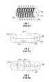
- a typical loose braid coaxial cableis shown in FIG. 1 and includes an inner conductor 120 , an outer conductor 150 coaxially surrounding the inner conductor 120 , and a dielectric material 140 separating the inner and outer conductors.
- the direction of the radiation pattern of the loose braid coaxial cableis indicated by the curved arrows in FIG. 1 .
- An example of a slotted coaxial cableis illustrated in FIG.
- the slotted coaxial cable illustrated in FIG. 2the slots 201 A, 201 B and 201 C longitudinally extend along the longitudinal axis of the inner conductor 220 .
- a plurality of slots 301 A, 301 B and 301 Care formed in the outer conductor 360 such that the longitudinal axis of each slot extends perpendicular to the longitudinal axis of the central conductor 320 .
- the present disclosurerelates to a device for directing energy to a target volume of tissue including a proximal portion including a first antenna subassembly extending therethrough, and a distal portion including a second antenna subassembly.
- the first antenna subassemblyincludes a leaky-wave antenna assembly having an outer conductor and an inner conductor disposed within the outer conductor.
- the distal portion of the deviceis attached to the inner conductor.
- the outer conductorincludes a plurality of radiating apertures defined in a distal portion thereof and is configured for radiating energy substantially uniformly along a longitudinal axis of the proximal portion.
- the present disclosurealso relates to a method for directing energy to a target volume of tissue including the step of positioning a dual antenna assembly for delivery of energy to the target volume of tissue.
- the methodalso includes the steps of: operating a leaky-wave antenna assembly extending through a proximal portion of the dual antenna assembly, whereby a first portion of the energy is radiated through a plurality of apertures defined in the leaky-wave antenna assembly, the apertures configured for radiating energy substantially uniformly along a longitudinal axis of the leaky-wave antenna assembly; and operating an antenna subassembly, the antenna subassembly electrically coupled to the leaky-wave antenna assembly and disposed in a distal portion of the dual antenna assembly.
- FIG. 1is a perspective view of a prior art loose braid coaxial cable
- FIG. 2is a perspective view of a prior art slotted coaxial cable
- FIG. 3is a perspective view of another prior art slotted coaxial cable
- FIG. 4is a perspective view of a leaky-wave antenna assembly according to an embodiment of the present disclosure.
- FIG. 5is a perspective view of another embodiment of a leaky-wave antenna assembly according to the present disclosure.
- FIG. 6is a perspective view of yet another embodiment of a leaky-wave antenna assembly according to the present disclosure.
- FIG. 7is a perspective view of a leaky-wave antenna assembly configured with inclusion elements extending inwardly from the outer conductor according to an embodiment of the present disclosure
- FIG. 8Ais an enlarged view of the indicated area of detail of FIG. 7 according to an embodiment of the present disclosure.
- FIG. 8Bis an enlarged view of the indicated area of detail of FIG. 7 according to another embodiment of the present disclosure.
- FIG. 9is a perspective view of another embodiment of a leaky-wave antenna assembly configured with inclusion elements extending inwardly from the outer conductor according to the present disclosure.
- FIG. 10is a perspective view of the leaky-wave antenna assembly illustrated in FIG. 5 shown with inclusion elements extending inwardly from the outer conductor according to an embodiment of the present disclosure
- FIG. 11is a perspective view of the leaky-wave antenna assembly illustrated in FIG. 6 shown with inclusion elements extending inwardly from the outer conductor according to an embodiment of the present disclosure
- FIGS. 12A and 12Bare schematic diagrams of a leaky-wave antenna assembly including a sleeve member according to an embodiment of the present disclosure
- FIG. 13is a schematic diagram of a leaky-wave antenna assembly including a sleeve member according to another embodiment of the present disclosure
- FIG. 14is a flowchart illustrating a method of directing energy to a target volume of tissue according to an embodiment of the present disclosure
- FIG. 15is a schematic diagram showing the basic geometry of a helical antenna
- FIG. 16is a schematic diagram showing a dual antenna assembly including a leaky-wave antenna assembly and a helical antenna assembly according to an embodiment of the present disclosure
- FIG. 17is a perspective view of a portion of the helical antenna assembly shown in FIG. 16 taken along the lines II-II;
- FIG. 18is a cross-sectional view of the helical antenna radiating section shown in FIG. 17 ;
- FIG. 19is a cross-sectional view of the helical antenna radiating section of FIG. 17 shown with a dielectric material located in an interior of the helical antenna element according to an embodiment of the present disclosure
- FIG. 20is a schematic diagram showing a dual antenna assembly according to an embodiment of the present disclosure.
- FIG. 21is a perspective view of a dual antenna assembly including a leaky-wave antenna assembly and a microstrip antenna assembly according to an embodiment of the present disclosure
- FIG. 22is a cross-sectional view of the distal portion of the dual antenna assembly of FIG. 21 ;
- FIG. 23is a flowchart illustrating a method of directing energy to a target volume of tissue according to an embodiment of the present disclosure.
- Electromagnetic energyis generally classified by increasing energy or decreasing wavelength into radio waves, microwaves, infrared, visible light, ultraviolet, X-rays and gamma-rays.
- microwavegenerally refers to electromagnetic waves in the frequency range of 300 megahertz (MHz) (3 ⁇ 10 8 cycles/second) to 300 gigahertz (GHz) (3 ⁇ 10 11 cycles/second).
- ablation proceduregenerally refers to any ablation procedure, such as microwave ablation or microwave ablation assisted resection.
- transmission linegenerally refers to any transmission medium that can be used for the propagation of signals from one point to another.
- a leaky-wave antenna assemblyis capable of radiating energy substantially uniformly along the longitudinal axis of the leaky-wave antenna assembly.
- Multiple leaky-wave antenna assembliescan be employed in variously arranged configurations. For example, multiple leaky-wave antenna assemblies can be placed parallel to each other to substantially simultaneously ablate a target volume of tissue.
- Various embodiments of the presently disclosed leaky-wave antenna assemblyare suitable for microwave ablation and for use to pre-coagulate tissue for microwave ablation assisted surgical resection.
- various methods described hereinbeloware targeted toward microwave ablation and the complete destruction of target tissue, it is to be understood that methods for directing electromagnetic radiation may be used with other therapies in which the target tissue is partially destroyed or damaged, such as, for example, to prevent the conduction of electrical impulses within heart tissue.
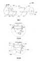
- FIG. 4shows a leaky-wave antenna assembly according to an embodiment of the present disclosure.
- the leaky-wave antenna assembly 400includes an inner conductor 420 having a length “L” and an outer conductor 460 coaxially surrounding the inner conductor 420 along the length “L”.
- Leaky-wave antenna assembly 400may include a dielectric material 440 separating the inner conductor 420 and outer conductor 460 .
- Dielectric material 440may include ceramics, water, mica, polyethylene, glass, or metal oxides.
- Leaky-wave antenna assembly 400may include an electrical short element (not shown) located at the distal end of the device for electrically connecting the inner conductor 420 and the outer conductor 460 , such as a solder cap, metal plate or wire.
- the distal portion of the outer conductor 460is provided with a plurality of apertures for radiating energy.
- the aperturesare configured for radiating energy substantially uniformly along the longitudinal axis of the distal portion of the outer conductor 460 , e.g., to provide uniform ablation to the target tissue volume surrounding the leaky-wave antenna assembly 400 .
- each of the apertures(referred to herein as slots 401 , 402 , 403 and 404 ) has a different size and longitudinally extends parallel to the longitudinal axis of the central conductor 420 .
- Slots 401 , 402 , 403 and 404are disposed in increasing order of size along the length of the distal portion of the outer conductor 460 , which may increase radiation, since larger slots generally perturb currents more.
- Leaky-wave antenna assembly 400may be axially rigid to allow for tissue penetration. Leaky-wave antenna assembly 400 may be sufficiently small in diameter to be minimally invasive of the body, which may reduce the preparation time of the patient as might be required for more invasive penetration of the body. Leaky-wave antenna assembly 400 may include a tip portion that is advantageously dimensioned and shaped to facilitate penetration of tissue. The proximal end of the leaky-wave antenna assembly 400 may be coupled to a transmission line that electrically connects the leaky-wave antenna assembly 400 to a microwave energy source.
- FIG. 5shows another embodiment of a leaky-wave antenna assembly.
- Leaky-wave antenna assembly 500 shown in FIG. 5includes an inner conductor 520 and an outer conductor 560 coaxially surrounding the inner conductor 520 , and may include a dielectric material 540 separating the inner conductor 520 and the outer conductor 560 .
- Dielectric material 540may include ferroelectric dielectric materials.
- the distal portion of the outer conductor 560is provided with a plurality of apertures for radiating energy. The apertures are configured for radiating energy substantially uniformly along the longitudinal axis of the distal portion of the outer conductor 560 .
- radiationcan be increased by placing each aperture in a position that causes high perturbation of the currents inside the guiding structure, i.e., transversal to the current lines, so that a high number of current lines is cut and perturbed by the apertures.
- the sizes of the respective apertures and the leaky-wave antenna assembly 500are based on at least one of the location of each aperture relative to a distal tip of the leaky-wave antenna assembly 500 and the angle of each aperture relative to the longitudinal axis of the central conductor 520 .
- the number, shape, size, angle and relative spacing of the aperturesmay be varied from the configuration depicted in FIG. 5 .
- the energy radiated from each of the aperturesis substantially the same.
- the apertures(referred to herein as the first, second, third, fourth and fifth slots 501 , 502 , 503 , 504 and 505 , respectively) each have a different size.
- the first, second, third, fourth and fifth slots 501 , 502 , 503 , 504 and 505are positioned along the distal portion of the outer conductor 560 in order of increasing size, such that the first slot 501 , which is the smallest opening, is disposed furthest from the distal end of the distal portion of the outer conductor 560 , and the fifth slot 505 , which is the largest opening, is disposed closest to the distal end.
- First, third and fifth slots 501 , 503 and 505longitudinally extend in a first direction at substantially the same angle relative to the longitudinal axis of the central conductor 520 .
- Second and fourth slots 502 and 504longitudinally extend in a second direction at substantially the same angle relative to the longitudinal axis of the central conductor 520 .
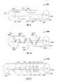
- FIG. 6shows another embodiment of a leaky-wave antenna assembly and includes an inner conductor 620 and an outer conductor 660 coaxially surrounding the inner conductor 620 .
- the distal portion of the outer conductor 660is provided with a plurality of apertures for radiating energy.
- the apertures(referred to herein as the first, second, third, fourth, fifth and sixth slots 601 , 602 , 603 , 604 , 605 and 606 ) are configured for radiating energy substantially uniformly along the longitudinal axis of the outer conductor 660 .
- each of the first, second, third, fourth, fifth and sixth slots 601 , 602 , 603 , 604 , 605 and 606are substantially the same size.
- Leaky-wave antenna assembly 600may include a dielectric material 640 separating the inner conductor 620 and the outer conductor 660 .
- each of the substantially equal-sized first, second, third, fourth, fifth and sixth slots 601 , 602 , 603 , 604 , 605 and 606longitudinally extends at a different angle relative to the longitudinal axis of the central conductor 620 .
- the longitudinal axis of the sixth slot 606extends substantially perpendicular to the longitudinal axis of the central conductor 620
- the longitudinal axis of the first slot 601is near parallel to the longitudinal axis of the central conductor 620 .
- the microwave signalpropagates inside the leaky-wave antenna assembly 600 , it “leaks” out through the first, second, third, fourth, fifth and sixth slots 601 , 602 , 603 , 604 , 605 and 606 , causing substantially uniform radiation along the longitudinal axis of the distal portion of the outer conductor 660 .
- FIG. 7shows another embodiment of a leaky-wave antenna assembly and includes an inner conductor 720 , an outer conductor 760 coaxially surrounding the inner conductor, a plurality of apertures (referred to herein as slots 701 , 702 , 703 and 704 , respectively) for radiating energy, and may include a dielectric material 740 separating the inner and outer conductors.
- Leaky-wave antenna assembly 700is similar to the leaky-wave antenna assembly 400 illustrated in FIG. 4 , except that the leaky-wave antenna assembly 700 further includes inclusion elements 711 , 712 , 713 and 714 extending inwardly from the outer conductor 760 .
- Each inclusion element 711 , 712 , 713 and 714extends inwardly toward the inner conductor 720 at an angle relative to a plane substantially coextensive with the corresponding one of the slots 701 , 702 , 703 or 704 .
- Inclusion elements 711 , 712 , 713 and 714each have a size, a shape, and an edge disposed substantially adjacent to an edge of a corresponding one of the slots 701 , 702 , 703 or 704 .
- the size, shape and/or angle of each inclusion element 711 , 712 , 713 and 714may be based on a wavelength of the energy to be radiated along the outer conductor 760 .
- the size, shape and/or angle of each inclusion element 711 , 712 , 713 and 714may be based on the location of the corresponding one of the slots 701 , 702 , 703 or 704 relative to the distal tip of the leaky-wave antenna assembly 700 .
- FIG. 8Ais an enlarged view of the slot 701 and the inclusion element 711 illustrated in FIG. 7 shown with example dimensions of the slot 701 and the inclusion element 711 .
- the slot 701has a length “L 1 ” and a width “W 1 ”, and the inclusion element 711 has a length “L 2 ” and a width “W 1 ”.
- the angle formed between the inclusion element 711 and a plane substantially coextensive with the corresponding one of the slot 701is indicated by the arc labeled “A”.
- the inclusion elements 711 , 712 , 713 and 714each have equal width “W 1 ”; a first subset of the inclusion elements 711 and 713 have equal length “L 2 ”; and a second subset of inclusion elements 712 and 714 have an equal length that is different than the length “L 2 ” of the first set of inclusion elements.
- the lengths and widths of the apertures and inclusion elementsmay be varied from the configuration depicted in FIGS. 7 and 8A .
- FIG. 8Bis an enlarged view of the slot 701 and the inclusion element 711 illustrated in FIG. 7 shown with a dielectric pocket “P” having an upper surface 801 , a lower surface 802 opposed to the upper surface 801 , a first side surface 811 , a second side surface 812 , and a third side surface 813 .
- the dielectric pocket “P”has a wedge-like shape, wherein each of the first and second side surfaces 811 , 812 has a substantially rectangular shape with the first side surface 811 having a length “L 1 ” and a width “W 1 ” and the second side surface 812 having a length “L 2 ” and a width “W 1 ”.
- the shape and volume of the dielectric pocket “P”may be varied from the configuration depicted in FIG. 8B .
- Dielectric pocket “P”may be formed of material with a dielectric constant different than the dielectric constant of the dielectric material 740 .
- the dielectric pocket “P”may be formed of a material with a dielectric constant higher than the dielectric constant of the dielectric material 740 , which may tend to concentrate more electric fields within the volume of the dielectric pocket “P”.
- Dielectric pocket “P”may be formed of a material with a dielectric constant lower than the dielectric constant of the dielectric material 740 , which may tend to lessen the electric fields within the volume of the dielectric pocket “P”.
- Dielectric pocket “P”may be configured to assist in uniformity of leaky behavior of the leaky-wave antenna assembly 700 .
- respective widths of the inclusion elementsmay be larger, smaller, and/or substantially equal to the width “W 1 ” of the slots 701 , 702 , 703 and 704 . It is contemplated herein that some apertures may not be provided with an inclusion element and/or some apertures may be provided with a plurality of inclusion elements. Inclusion elements may be integrally formed with the outer conductor 760 , for example, by punching, bending and/or cutting of the material of the outer conductor 760 , such that the apertures and the inclusion elements are commonly formed. Alternatively, the inclusion elements may be separately fabricated from any suitable electrically conductive materials and attached to an inner diametric surface of the outer conductor 760 , e.g., by solder or adhesive.
- FIG. 9shows another embodiment of a leaky-wave antenna assembly and includes an inner conductor 920 , an outer conductor 960 coaxially surrounding the inner conductor, and a plurality of apertures (referred to herein as first, second, third and fourth slots 901 , 902 , 903 and 904 , respectively) for radiating energy.
- Leaky-wave antenna assembly 900may include a dielectric material 940 separating the inner and outer conductors.
- Leaky-wave antenna assembly 900is also similar to the leaky-wave antenna assembly 400 illustrated in FIG. 4 , except that the leaky-wave antenna assembly 900 further includes inclusion elements 911 , 912 , 913 and 914 extending inwardly from the outer conductor 960 .
- Inclusion elements 911 , 912 , 913 and 914are similar to the inclusion elements 711 , 712 , 713 and 714 shown in FIG. 7 , except that the inclusion elements 911 , 912 , 913 and 914 are respectively disposed substantially adjacent to a proximal edge of the slots 901 , 902 , 903 and 904 , i.e., instead of a distal edge thereof as shown in FIG. 7 .
- Leaky-wave antenna assembly 900may include dielectric pockets (not shown), e.g., similar to the dielectric pocket “P” shown in FIG. 8B , which may be formed of a material with a dielectric constant different than the dielectric constant of the dielectric material 940 .
- FIG. 10shows yet another embodiment of a leaky-wave antenna assembly and includes an inner conductor 1020 , an outer conductor 1060 coaxially surrounding the inner conductor, and a plurality of apertures (herein referred to as first, second, third, fourth and fifth slots 1001 , 1002 , 1003 , 1004 and 1005 , respectively) for radiating energy, and may include a dielectric material 1040 separating the inner and outer conductors.
- Leaky-wave antenna assembly 1000further includes a number of inclusion elements 1011 , 1012 , 1013 , 1014 and 1015 extending inwardly from the outer conductor 1020 . In this embodiment, the inclusion elements 1011 , 1012 , 1013 1014 and 1015 each have a different size.
- each of the first, second, third, fourth and fifth slots 1001 , 1002 , 1003 , 1004 and 1005longitudinally extends at a different angle relative to the longitudinal axis of the central conductor 1020 .
- a first subset of the inclusion elements 1011 , 1012 , 1013 and 1014are respectively disposed substantially adjacent to a distal edge of the slots 1001 , 1002 , 1003 and 1004
- a second subset, i.e., inclusion element 1015is disposed substantially adjacent to a proximal edge of the slot 1005 .
- Leaky-wave antenna assembly 1000may include dielectric pockets (not shown), e.g., similar to the dielectric pocket “P” shown in FIG. 8B , which may be formed of a material with a dielectric constant different than the dielectric constant of the dielectric material 1040 .
- FIG. 11shows yet another embodiment of a leaky-wave antenna assembly and includes an inner conductor 1120 , an outer conductor 1160 coaxially surrounding the inner conductor, and a plurality of apertures (referred to herein as slots 1101 , 1102 , 1103 , 1104 , 1105 and 1106 , respectively) for radiating energy, and may include a dielectric material 1140 separating the inner and outer conductors.
- Leaky-wave antenna assembly 1100further includes a number of inclusion elements 1111 , 1112 , 1113 , 1114 , 1115 and 1116 extending inwardly from the outer conductor 1120 .
- Each inclusion element 1111 , 1112 , 1113 , 1114 , 1115 and 1116extends inwardly toward the inner conductor 1120 at an angle relative to a plane substantially coextensive with the slots 1101 , 1102 , 1103 , 1104 , 1105 and 1106 , respectively.
- the size, shape and/or angle of each inclusion element 1111 , 1112 , 1113 , 1114 , 1115 and 1116may be based on a wavelength of the energy to be radiated along the length of the outer conductor 1160 .
- each inclusion element 1111 , 1112 , 1113 , 1114 , 1115 and 1116may be based on the location of the corresponding one of the slots 1101 , 1102 , 1103 , 1104 , 1105 and 1106 relative to the distal tip of the leaky-wave antenna assembly 700 .
- the microwave signalpropagates inside the leaky-wave antenna assembly 1100 , it “leaks” out through the slots 1101 , 1102 , 1103 , 1104 , 1105 and 1106 , causing substantially uniform radiation along the longitudinal axis of the distal portion of the outer conductor 1160 .
- Leaky-wave antenna assembly 1100may include dielectric pockets (not shown), e.g., similar to the dielectric pocket “P” shown in FIG. 8B , which may be formed of a material with a dielectric constant different than the dielectric constant of the dielectric material 1140 .
- FIGS. 12A and 12Bshow a leaky-wave antenna assembly 1200 including a moveable sleeve member 1220 located at a periphery of the outer conductor 1260 coaxially with the outer conductor 1260 .
- Sleeve member 1220is adapted to be slideably moveable along the periphery of the leaky-wave antenna assembly 1200 between a first position, in which a first portion 1240 A of the distal portion of the outer conductor 1260 is exposed, and a second position, in which a second portion 1240 B larger than the first portion 1240 A of the distal portion of the outer conductor 1260 is exposed.
- a first positionin which a first portion 1240 A of the distal portion of the outer conductor 1260 is exposed
- second positionin which a second portion 1240 B larger than the first portion 1240 A of the distal portion of the outer conductor 1260 is exposed.
- a first set of apertures 1201 , 1202 and 1203are exposed, and when the sleeve member 1220 is in the second position shown in FIG. 12B , a second set of apertures 1201 , 1202 , 1203 , 1204 and 1205 are exposed.
- the leaky-wave antenna assembly 1200is operated with the sleeve member in the first position, the energy is applied to a first portion of the target volume of tissue “T”, and when the leaky-wave antenna assembly 1200 is operated with the sleeve member 1220 in the second position, the energy is applied to a second portion larger than the first portion of the target volume of tissue “T”.
- Sleeve member 1220 shown in FIGS. 12A and 12Bis a substantially cylindrical shaped structure having an inner diameter “D I ”, which is larger than an outer diameter “D O ” of the outer conductor 1260 .
- the sleeve member 1220is slideably movable to various positions such that any suitable number of apertures may be exposed.
- the number of apertures to be exposedmay be based on various factors, such as, for example, the volume of target tissue to be treated, the desired procedure, the wavelength of the energy to be radiated, and the shape and dimensions of the apertures.
- FIG. 13Ashows a leaky-wave antenna 1300 including a moveable sleeve member 1320 located at a periphery of the outer conductor 1360 coaxially with the outer conductor 1360 .
- Sleeve member 1320is adapted to be rotationably moveable and slideably moveable along the periphery of the leaky-wave antenna assembly 1300 to various positions or various rotation positions to vary slot openings with rotation angle.
- Sleeve member 1320includes a plurality of apertures 1321 , 1322 , 1323 , 1324 and 1325 and can be positioned relative to the outer conductor 1360 such that any suitable number of slot openings may be exposed.
- the sleeve member 1320is moveable such that the apertures 1321 , 1322 , 1323 , 1324 and 1325 are respectively positioned in alignment with the slots 1301 , 1302 , 1303 , 1304 and 1305 in the outer conductor 1360 to create leaky-wave openings.
- the number, shape and pattern of apertures in the sleeve member 1320may be varied from the configuration depicted in FIG. 13 and may be selectable by a user, e.g., for a particular antenna deposition pattern.
- FIG. 14is a flowchart illustrating a method of directing energy to a target volume of tissue.
- a leaky-wave antenna assemblye.g., 400
- Leaky-wave antenna assembly 400may be inserted directly into tissue (e.g., as shown in FIGS. 12A and 12B ), inserted through a lumen, e.g., a vein, needle or catheter, placed into the body during surgery by a clinician, or positioned in the body by other suitable methods known in the art.
- step 1420energy from an energy source is transmitted to the leaky-wave antenna assembly.
- the energy sourcemay be any suitable electrosurgical generator for generating an output signal.
- the energy sourceis a microwave energy source.
- the energyis applied through a plurality of radiating apertures, e.g., 401 , 402 , 403 and 404 , in a distal portion of the leaky-wave antenna assembly.
- the radiating apertures 401 , 402 , 403 and 404are configured for radiating energy along the longitudinal axis of the leaky-wave antenna assembly 400 .
- the size and/or the angle of each aperture relative to the inner conductor 420 of the leaky-wave antenna assembly 400may be varied in relation to the other apertures such that the energy radiated along the leaky-wave antenna assembly 400 is substantially uniform.
- At least a subset of the radiating aperturesmay extend at different angles relative to the longitudinal axis of the leaky-wave antenna assembly.
- the size and/or the angle of each aperture relative to the inner conductor 420may be varied in relation to the other apertures such that the energy radiated along the leaky-wave antenna assembly 400 may have a substantially pear shape, hour-glass shape or other shape.
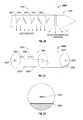
- a typical helical antennais illustrated in FIG. 15 and includes a conducting wire 1500 that is coiled to form a helix having an axis 1520 and backed by a conducting ground plane 1510 .
- the helical antennaradiates in the normal mode (similar to dipole antenna radiation).
- the helical antennaWhen the helix circumference is about one wavelength, the helical antenna operates in the axial mode. Typically, a helical antenna radiates in the normal mode when C ⁇ 0.4 ⁇ ( ⁇ is the wavelength) and in the axial mode for approximately 0.75 ⁇ C ⁇ 1.3 ⁇ .
- FIG. 16shows an embodiment of a dual antenna assembly including a leaky-wave antenna assembly and a helical antenna assembly.
- the leaky-wave antenna assembly 1650 shown in FIG. 16is similar to the leaky-wave antenna assembly 400 of FIG. 4 and further description thereof is omitted in the interests of brevity.
- the helical antenna assembly 1690 shown in FIG. 16includes a helical antenna radiating section 1660 and a tip portion 1665 .
- Tip portion 1665is configured for penetrating tissue.
- the surfaces of the tip portion 1665 shown in FIG. 16are generally flat, the surfaces of the tip portion 1665 according to various embodiments may be curved or may include a combination of flat, sloped or curved portions.
- the shape and size of the tip portion 1665may be varied from the configuration depicted in FIG. 16 .
- the helical antenna radiating section 1660includes a helical antenna element 1610 .
- FIG. 17shows a portion of the helical antenna assembly of FIG. 16 taken along the lines II-II.
- the helical antenna radiating section 1660includes a distal end 1764 .
- Helical antenna assembly 1600can be operated in the axial mode to perform a procedure on a first portion of a target volume of tissue, wherein the first portion of the tissue is located distal to end 1764 of the helical antenna assembly 1600 .
- Helical antenna assembly 1600can be operated in the normal mode to perform a second procedure on a second portion of the target volume of tissue, wherein the second portion is located substantially adjacent to the helical antenna radiating section 1660 .
- Various sequences of axial and normal modes of operationmay be utilized depending on the particular application of the helical antenna assembly 1600 .
- the helical antenna radiating section 1660further includes a sleeve portion 1721 located at the periphery of the helical antenna element 1610 coaxially with the helical antenna element 1610 , and a cavity 1780 located to the interior of the helical antenna element 1610 .
- the sleeve portion 1721is formed of a dielectric material and may include a material that has variable dielectric constant, or adjustable dielectric constant, so that effective wavelengths will vary between the axial mode and the normal mode of operation.
- FIG. 18is a cross-sectional view of the helical antenna radiating section of FIG. 17 .
- FIG. 18shows the helical antenna radiating section 1560 including the helical antenna element 1610 enclosed by a first dielectric material 1721 .
- First dielectric material 1721may include ferroelectric dielectric materials, which through applied DC voltage may allow control of the depth and spread of the power deposition pattern.
- FIG. 19is a cross-sectional view of the helical antenna radiating section of FIG. 17 shown with a dielectric material located in an interior of the helical antenna element.
- Helical antenna radiating section 1800is similar to the helical antenna radiating section 1600 shown in FIG. 18 , except that the helical antenna radiating section 1800 includes a second dielectric material 1880 disposed to the interior of the helical antenna element 1610 , i.e., instead of the cavity 1780 .
- Second dielectric material 1880may include ferroelectric dielectric materials.
- FIG. 20shows another embodiment of a dual antenna assembly.
- the dual antenna assembly 1900 illustrated in FIG. 20includes a proximal portion 1950 and a distal portion 1980 .
- Proximal portion 1950includes a leaky-wave antenna assembly having a plurality of slots 1901 , 1902 , 1903 , 1904 and 1905 .
- Distal portion 1980includes either a dipole or monopole antenna assembly.
- the arrows in FIG. 20show the leaky radiation along the proximal portion 1950 and the dipole (or monopole) radiation on the distal portion 1980 .
- FIG. 21shows yet another embodiment of a dual antenna assembly.
- Dual antenna assembly 2000includes a leaky-wave antenna assembly 2050 and a microstrip antenna assembly 2070 .
- Leaky-wave antenna assembly 2050includes an outer conductor 2060 , which is provided with a plurality of slots 2001 , 2002 , 2003 and 2004 for radiating energy, and an inner conductor 2020 .
- Microstrip antenna assembly 2070includes a lower conductor 2066 , which is electrically connected to the outer conductor 2060 of the leaky-wave antenna assembly 2050 , and a central conductor 2022 , which is electrically connected to the inner conductor 2020 of the leaky-wave antenna assembly 2050 .
- FIG. 22is a cross-sectional view of the distal portion of the dual antenna assembly illustrated in FIG. 21 . As shown in FIG. 22 , a dielectric material 2030 is disposed adjacent to the lower conductor 2066 .
- FIG. 23is a flowchart illustrating a method of directing energy to a target volume of tissue.
- a dual antenna assemblye.g., 1600 , is positioned for delivery of energy to the target volume of tissue.
- step 2320energy from an energy source is transmitted to the dual antenna assembly 1600 .
- the energy sourcemay be an electrosurgical generator for generating an output signal.
- the energy sourceis a microwave energy source.
- a first antenna subassemblyis operated, the first antenna subassembly being a leaky-wave antenna assembly, e.g., 400 , extending through a proximal portion of the dual antenna assembly, whereby a first portion of the energy is radiated through a plurality of apertures in the leaky-wave antenna assembly 400 , the apertures being configured for radiating energy substantially uniformly along a longitudinal axis of the leaky-wave antenna assembly 400 .
- a second antenna subassemblye.g., 1660
- the second antenna subassembly 1660being electrically coupled to the first antenna subassembly 400 and disposed in a distal portion of the dual antenna assembly 1600 .
- uniform radiation with a leaky-wave coaxial cableis achieved by compensating for signal attenuation along the cable (stronger signal proximally, close to generator, and weaker signal distally) by varying slots size and/or slot direction so that smaller slots and/or slots angled more parallel to the cable axis are placed proximally (where the signal is stronger), while larger slots and/or slots transverse to the cable axis are placed distally (where the signal has been attenuated more), with gradual change in slot size and/or direction in between.
Landscapes
- Health & Medical Sciences (AREA)
- Surgery (AREA)
- Life Sciences & Earth Sciences (AREA)
- Biomedical Technology (AREA)
- Medical Informatics (AREA)
- Nuclear Medicine, Radiotherapy & Molecular Imaging (AREA)
- Electromagnetism (AREA)
- Engineering & Computer Science (AREA)
- Physics & Mathematics (AREA)
- Heart & Thoracic Surgery (AREA)
- Otolaryngology (AREA)
- Molecular Biology (AREA)
- Animal Behavior & Ethology (AREA)
- General Health & Medical Sciences (AREA)
- Public Health (AREA)
- Veterinary Medicine (AREA)
- Surgical Instruments (AREA)
Abstract
Description
Claims (20)
Priority Applications (1)
| Application Number | Priority Date | Filing Date | Title |
|---|---|---|---|
| US13/526,676US8608731B2 (en) | 2009-02-20 | 2012-06-19 | Leaky-wave antennas for medical applications |
Applications Claiming Priority (2)
| Application Number | Priority Date | Filing Date | Title |
|---|---|---|---|
| US12/389,915US8202270B2 (en) | 2009-02-20 | 2009-02-20 | Leaky-wave antennas for medical applications |
| US13/526,676US8608731B2 (en) | 2009-02-20 | 2012-06-19 | Leaky-wave antennas for medical applications |
Related Parent Applications (1)
| Application Number | Title | Priority Date | Filing Date |
|---|---|---|---|
| US12/389,915ContinuationUS8202270B2 (en) | 2009-02-20 | 2009-02-20 | Leaky-wave antennas for medical applications |
Publications (2)
| Publication Number | Publication Date |
|---|---|
| US20120259328A1 US20120259328A1 (en) | 2012-10-11 |
| US8608731B2true US8608731B2 (en) | 2013-12-17 |
Family
ID=42631604
Family Applications (2)
| Application Number | Title | Priority Date | Filing Date |
|---|---|---|---|
| US12/389,915Active2030-09-21US8202270B2 (en) | 2009-02-20 | 2009-02-20 | Leaky-wave antennas for medical applications |
| US13/526,676ActiveUS8608731B2 (en) | 2009-02-20 | 2012-06-19 | Leaky-wave antennas for medical applications |
Family Applications Before (1)
| Application Number | Title | Priority Date | Filing Date |
|---|---|---|---|
| US12/389,915Active2030-09-21US8202270B2 (en) | 2009-02-20 | 2009-02-20 | Leaky-wave antennas for medical applications |
Country Status (1)
| Country | Link |
|---|---|
| US (2) | US8202270B2 (en) |
Cited By (4)
| Publication number | Priority date | Publication date | Assignee | Title |
|---|---|---|---|---|
| US9598945B2 (en) | 2013-03-15 | 2017-03-21 | Chevron U.S.A. Inc. | System for extraction of hydrocarbons underground |
| US10022186B2 (en) | 2008-08-28 | 2018-07-17 | Covidien Lp | Microwave antenna with cooled handle |
| EP3584887A1 (en)* | 2018-06-19 | 2019-12-25 | Premix Oy | Dielectric-based leaky-wave structure |
| US10631922B2 (en) | 2008-02-07 | 2020-04-28 | Covidien Lp | Endoscopic instrument for tissue identification |
Families Citing this family (59)
| Publication number | Priority date | Publication date | Assignee | Title |
|---|---|---|---|---|
| US7553309B2 (en) | 2004-10-08 | 2009-06-30 | Covidien Ag | Electrosurgical system employing multiple electrodes and method thereof |
| US7777130B2 (en)* | 2007-06-18 | 2010-08-17 | Vivant Medical, Inc. | Microwave cable cooling |
| US9622813B2 (en) | 2007-11-01 | 2017-04-18 | Covidien Lp | Method for volume determination and geometric reconstruction |
| US8280525B2 (en) | 2007-11-16 | 2012-10-02 | Vivant Medical, Inc. | Dynamically matched microwave antenna for tissue ablation |
| US8945111B2 (en) | 2008-01-23 | 2015-02-03 | Covidien Lp | Choked dielectric loaded tip dipole microwave antenna |
| US8435237B2 (en) | 2008-01-29 | 2013-05-07 | Covidien Lp | Polyp encapsulation system and method |
| US9949794B2 (en) | 2008-03-27 | 2018-04-24 | Covidien Lp | Microwave ablation devices including expandable antennas and methods of use |
| US8192427B2 (en) | 2008-06-09 | 2012-06-05 | Tyco Healthcare Group Lp | Surface ablation process with electrode cooling methods |
| US8403924B2 (en) | 2008-09-03 | 2013-03-26 | Vivant Medical, Inc. | Shielding for an isolation apparatus used in a microwave generator |
| US8197473B2 (en) | 2009-02-20 | 2012-06-12 | Vivant Medical, Inc. | Leaky-wave antennas for medical applications |
| US8202270B2 (en)* | 2009-02-20 | 2012-06-19 | Vivant Medical, Inc. | Leaky-wave antennas for medical applications |
| US9277969B2 (en) | 2009-04-01 | 2016-03-08 | Covidien Lp | Microwave ablation system with user-controlled ablation size and method of use |
| US8463396B2 (en) | 2009-05-06 | 2013-06-11 | Covidien LLP | Power-stage antenna integrated system with high-strength shaft |
| US8246615B2 (en) | 2009-05-19 | 2012-08-21 | Vivant Medical, Inc. | Tissue impedance measurement using a secondary frequency |
| US8292881B2 (en) | 2009-05-27 | 2012-10-23 | Vivant Medical, Inc. | Narrow gauge high strength choked wet tip microwave ablation antenna |
| US8235981B2 (en)* | 2009-06-02 | 2012-08-07 | Vivant Medical, Inc. | Electrosurgical devices with directional radiation pattern |
| US8328799B2 (en) | 2009-08-05 | 2012-12-11 | Vivant Medical, Inc. | Electrosurgical devices having dielectric loaded coaxial aperture with distally positioned resonant structure |
| USD634010S1 (en) | 2009-08-05 | 2011-03-08 | Vivant Medical, Inc. | Medical device indicator guide |
| US9031668B2 (en)* | 2009-08-06 | 2015-05-12 | Covidien Lp | Vented positioner and spacer and method of use |
| US9113925B2 (en)* | 2009-09-09 | 2015-08-25 | Covidien Lp | System and method for performing an ablation procedure |
| US8069553B2 (en) | 2009-09-09 | 2011-12-06 | Vivant Medical, Inc. | Method for constructing a dipole antenna |
| US8355803B2 (en) | 2009-09-16 | 2013-01-15 | Vivant Medical, Inc. | Perfused core dielectrically loaded dipole microwave antenna probe |
| US9095359B2 (en) | 2009-09-18 | 2015-08-04 | Covidien Lp | Tissue ablation system with energy distribution |
| US8394087B2 (en)* | 2009-09-24 | 2013-03-12 | Vivant Medical, Inc. | Optical detection of interrupted fluid flow to ablation probe |
| US8568398B2 (en) | 2009-09-29 | 2013-10-29 | Covidien Lp | Flow rate monitor for fluid cooled microwave ablation probe |
| US9113926B2 (en) | 2009-09-29 | 2015-08-25 | Covidien Lp | Management of voltage standing wave ratio at skin surface during microwave ablation |
| US8568401B2 (en) | 2009-10-27 | 2013-10-29 | Covidien Lp | System for monitoring ablation size |
| US8430871B2 (en) | 2009-10-28 | 2013-04-30 | Covidien Lp | System and method for monitoring ablation size |
| US8382750B2 (en)* | 2009-10-28 | 2013-02-26 | Vivant Medical, Inc. | System and method for monitoring ablation size |
| US8394092B2 (en)* | 2009-11-17 | 2013-03-12 | Vivant Medical, Inc. | Electromagnetic energy delivery devices including an energy applicator array and electrosurgical systems including same |
| US8764744B2 (en) | 2010-01-25 | 2014-07-01 | Covidien Lp | System for monitoring ablation size |
| US8491579B2 (en) | 2010-02-05 | 2013-07-23 | Covidien Lp | Electrosurgical devices with choke shorted to biological tissue |
| US8968288B2 (en) | 2010-02-19 | 2015-03-03 | Covidien Lp | Ablation devices with dual operating frequencies, systems including same, and methods of adjusting ablation volume using same |
| US8617153B2 (en) | 2010-02-26 | 2013-12-31 | Covidien Lp | Tunable microwave ablation probe |
| US8728067B2 (en) | 2010-03-08 | 2014-05-20 | Covidien Lp | Microwave antenna probe having a deployable ground plane |
| US10039601B2 (en) | 2010-03-26 | 2018-08-07 | Covidien Lp | Ablation devices with adjustable radiating section lengths, electrosurgical systems including same, and methods of adjusting ablation fields using same |
| US8409188B2 (en) | 2010-03-26 | 2013-04-02 | Covidien Lp | Ablation devices with adjustable radiating section lengths, electrosurgical systems including same, and methods of adjusting ablation fields using same |
| US9192436B2 (en) | 2010-05-25 | 2015-11-24 | Covidien Lp | Flow rate verification monitor for fluid-cooled microwave ablation probe |
| US8652127B2 (en) | 2010-05-26 | 2014-02-18 | Covidien Lp | System and method for chemically cooling an ablation antenna |
| US9241762B2 (en) | 2010-06-03 | 2016-01-26 | Covidien Lp | Specific absorption rate measurement and energy-delivery device characterization using image analysis |
| US8672933B2 (en) | 2010-06-30 | 2014-03-18 | Covidien Lp | Microwave antenna having a reactively-loaded loop configuration |
| US10588684B2 (en) | 2010-07-19 | 2020-03-17 | Covidien Lp | Hydraulic conductivity monitoring to initiate tissue division |
| US8945144B2 (en) | 2010-09-08 | 2015-02-03 | Covidien Lp | Microwave spacers and method of use |
| USD673685S1 (en) | 2010-09-08 | 2013-01-01 | Vivant Medical, Inc. | Microwave device spacer and positioner with arcuate slot |
| US8968289B2 (en) | 2010-10-22 | 2015-03-03 | Covidien Lp | Microwave spacers and methods of use |
| US9028476B2 (en) | 2011-02-03 | 2015-05-12 | Covidien Lp | Dual antenna microwave resection and ablation device, system and method of use |
| US9620860B2 (en)* | 2011-02-28 | 2017-04-11 | Telefonaktiebolaget Lm Ericsson (Publ) | Slotted wave guide antenna with angled subsection |
| US9113931B2 (en) | 2012-01-06 | 2015-08-25 | Covidien Lp | System and method for treating tissue using an expandable antenna |
| US9119648B2 (en) | 2012-01-06 | 2015-09-01 | Covidien Lp | System and method for treating tissue using an expandable antenna |
| JP5628879B2 (en)* | 2012-10-23 | 2014-11-19 | 株式会社フジクラ | antenna |
| US10765477B2 (en) | 2014-03-10 | 2020-09-08 | Wisconsin Alumni Research Foundation | Microwave ablation antenna system |
| CN104490470B (en)* | 2014-12-29 | 2016-10-19 | 四川大学华西医院 | Multi-gap electromagnetic ablation knife |
| US11058487B2 (en)* | 2017-03-09 | 2021-07-13 | Wisconsin Alumni Research Foundation | Microwave ablation antenna system with reflector and slot |
| US10707581B2 (en) | 2018-01-03 | 2020-07-07 | Wisconsin Alumni Research Foundation | Dipole antenna for microwave ablation |
| GB201910527D0 (en) | 2019-07-23 | 2019-09-04 | Emblation Ltd | Microwave apparatus and method |
| WO2021050173A1 (en)* | 2019-09-10 | 2021-03-18 | Commscope Technologies Llc | Leaky waveguide antennas having spaced-apart radiating nodes with respective coupling ratios that support efficient radiation |
| EP4085862B1 (en)* | 2021-05-04 | 2024-05-29 | Endowave Ltd. | A microwave ablation probe |
| EP4340937A1 (en) | 2021-05-21 | 2024-03-27 | Emblation Limited | Microwave treatment of tissue |
| US12300878B2 (en)* | 2022-09-06 | 2025-05-13 | Oura Health Oy | Slot antenna in a wearable device |
Citations (144)
| Publication number | Priority date | Publication date | Assignee | Title |
|---|---|---|---|---|
| DE390937C (en) | 1922-10-13 | 1924-03-03 | Adolf Erb | Device for internal heating of furnace furnaces for hardening, tempering, annealing, quenching and melting |
| US2480181A (en) | 1945-01-24 | 1949-08-30 | Us Sec War | Directive high-frequency antenna |
| US2601610A (en) | 1948-03-18 | 1952-06-24 | Marconi Wireless Telegraph Co | Radio aerial installation |
| DE1099658B (en) | 1959-04-29 | 1961-02-16 | Siemens Reiniger Werke Ag | Automatic switch-on device for high-frequency surgical devices |
| FR1275415A (en) | 1960-09-26 | 1961-11-10 | Device for detecting disturbances for electrical installations, in particular electrosurgery | |
| DE1139927B (en) | 1961-01-03 | 1962-11-22 | Friedrich Laber | High-frequency surgical device |
| DE1149832B (en) | 1961-02-25 | 1963-06-06 | Siemens Reiniger Werke Ag | High frequency surgical apparatus |
| FR1347865A (en) | 1962-11-22 | 1964-01-04 | Improvements to diathermo-coagulation devices | |
| DE1439302A1 (en) | 1963-10-26 | 1969-01-23 | Siemens Ag | High-frequency surgical device |
| US3631363A (en) | 1969-11-14 | 1971-12-28 | Gen Electric | High-frequency cavity oscillator having improved tuning means |
| GB1321582A (en) | 1970-01-26 | 1973-06-27 | Sumitomo Electric Industries | Leaky coaxial cables |
| SU401367A1 (en) | 1971-10-05 | 1973-10-12 | Тернопольский государственный медицинский институт | BIAKTIVNYE ELECTRO SURGICAL INSTRUMENT |
| US3795915A (en)* | 1972-10-20 | 1974-03-05 | Sumitomo Electric Industries | Leaky coaxial cable |
| DE2439587A1 (en) | 1973-08-23 | 1975-02-27 | Matburn Holdings Ltd | ELECTROSURGICAL DEVICE |
| DE2455174A1 (en) | 1973-11-21 | 1975-05-22 | Termiflex Corp | INPUT / OUTPUT DEVICE FOR DATA EXCHANGE WITH DATA PROCESSING DEVICES |
| DE2407559A1 (en) | 1974-02-16 | 1975-08-28 | Dornier System Gmbh | Tissue heat treatment probe - has water cooling system which ensures heat development only in treated tissues |
| DE2415263A1 (en) | 1974-03-29 | 1975-10-02 | Aesculap Werke Ag | Surgical H.F. coagulation probe has electrode tongs - with exposed ends of insulated conductors forming tong-jaws |
| DE2429021A1 (en) | 1974-06-18 | 1976-01-08 | Erbe Elektromedizin | Remote control for HF surgical instruments - uses cable with two conductors at most |
| FR2235669B1 (en) | 1973-07-07 | 1976-05-07 | Lunacek Boris | |
| DE2460481A1 (en) | 1974-12-20 | 1976-06-24 | Delma Elektro Med App | Electrode grip for remote HF surgical instrument switching - has shaped insulated piece with contact ring of sterilizable (silicon) rubber |
| DE2602517A1 (en) | 1975-01-23 | 1976-07-29 | Dentsply Int Inc | ELECTROSURGICAL DEVICE |
| DE2504280A1 (en) | 1975-02-01 | 1976-08-05 | Hans Heinrich Prof Dr Meinke | DEVICE FOR ELECTRIC TISSUE CUTTING IN SURGERY |
| DE2627679A1 (en) | 1975-06-26 | 1977-01-13 | Marcel Lamidey | HEMATISTIC HIGH FREQUENCY EXTRACTOR FORCEPS |
| DE2540968A1 (en) | 1975-09-13 | 1977-03-17 | Erbe Elektromedizin | Circuit for bipolar coagulation tweezers - permits preparation of tissues prior to coagulation |
| FR2276027B3 (en) | 1974-06-25 | 1977-05-06 | Medical Plastics Inc | |
| DE2820908A1 (en) | 1977-05-16 | 1978-11-23 | Joseph Skovajsa | DEVICE FOR THE LOCAL TREATMENT OF A PATIENT IN PARTICULAR FOR ACUPUNCTURE OR AURICULAR THERAPY |
| DE2803275A1 (en) | 1978-01-26 | 1979-08-02 | Aesculap Werke Ag | HF surgical appts. with active treatment and patient electrodes - has sensor switching generator to small voltage when hand-operated switch is closed |
| DE2823291A1 (en) | 1978-05-27 | 1979-11-29 | Rainer Ing Grad Koch | Coagulation instrument automatic HF switching circuit - has first lead to potentiometer and second to transistor base |
| SU727201A2 (en) | 1977-11-02 | 1980-04-15 | Киевский Научно-Исследовательский Институт Нейрохирургии | Electric surgical apparatus |
| FR2313708B1 (en) | 1975-06-02 | 1980-07-04 | Sybron Corp | |
| DE2946728A1 (en) | 1979-11-20 | 1981-05-27 | Erbe Elektromedizin GmbH & Co KG, 7400 Tübingen | HF surgical appts. for use with endoscope - provides cutting or coagulation current at preset intervals and of selected duration |
| US4316474A (en) | 1979-08-17 | 1982-02-23 | Firma Electric Electronic Service Jens Spethmann | High frequency radiation therapy apparatus |
| DE3143421A1 (en) | 1980-11-04 | 1982-05-27 | The Agency of Industrial Science and Technology, Tokyo | Laser scalpel |
| DE3045996A1 (en) | 1980-12-05 | 1982-07-08 | Medic Eschmann Handelsgesellschaft für medizinische Instrumente mbH, 2000 Hamburg | Electro-surgical scalpel instrument - has power supply remotely controlled by surgeon |
| DE3120102A1 (en) | 1981-05-20 | 1982-12-09 | F.L. Fischer GmbH & Co, 7800 Freiburg | ARRANGEMENT FOR HIGH-FREQUENCY COAGULATION OF EGG WHITE FOR SURGICAL PURPOSES |
| FR2517953A1 (en) | 1981-12-10 | 1983-06-17 | Alvar Electronic | Diaphanometer for optical examination of breast tissue structure - measures tissue transparency using two plates and optical fibre bundle cooperating with photoelectric cells |
| US4397313A (en) | 1981-08-03 | 1983-08-09 | Clini-Therm Corporation | Multiple microwave applicator system and method for microwave hyperthermia treatment |
| US4462412A (en) | 1980-04-02 | 1984-07-31 | Bsd Medical Corporation | Annular electromagnetic radiation applicator for biological tissue, and method |
| FR2502935B1 (en) | 1981-03-31 | 1985-10-04 | Dolley Roger | METHOD AND DEVICE FOR CONTROLLING THE COAGULATION OF TISSUES USING A HIGH FREQUENCY CURRENT |
| US4572190A (en) | 1983-05-26 | 1986-02-25 | Cgr/Mev | Hyperthermia apparatus |
| DE3510586A1 (en) | 1985-03-23 | 1986-10-02 | Erbe Elektromedizin GmbH, 7400 Tübingen | Control device for a high-frequency surgical instrument |
| FR2573301B3 (en) | 1984-11-16 | 1987-04-30 | Lamidey Gilles | SURGICAL PLIERS AND ITS CONTROL AND CONTROL APPARATUS |
| DE3604823A1 (en) | 1986-02-15 | 1987-08-27 | Flachenecker Gerhard | HIGH FREQUENCY GENERATOR WITH AUTOMATIC PERFORMANCE CONTROL FOR HIGH FREQUENCY SURGERY |
| EP0246350A1 (en) | 1986-05-23 | 1987-11-25 | Erbe Elektromedizin GmbH. | Coagulation electrode |
| DE8712328U1 (en) | 1987-09-11 | 1988-02-18 | Jakoubek, Franz, 7201 Emmingen-Liptingen | Endoscopy forceps |
| DE3711511C1 (en) | 1987-04-04 | 1988-06-30 | Hartmann & Braun Ag | Method for determining gas concentrations in a gas mixture and sensor for measuring thermal conductivity |
| US4798215A (en) | 1984-03-15 | 1989-01-17 | Bsd Medical Corporation | Hyperthermia apparatus |
| US4841988A (en) | 1987-10-15 | 1989-06-27 | Marquette Electronics, Inc. | Microwave hyperthermia probe |
| US4934365A (en) | 1988-06-30 | 1990-06-19 | Massachusetts Institute Of Technology | Non-invasive hyperthermia method and apparatus |
| DE3904558A1 (en) | 1989-02-15 | 1990-08-23 | Flachenecker Gerhard | Radio-frequency generator with automatic power control for radio-frequency surgery |
| US4974587A (en) | 1988-12-22 | 1990-12-04 | Bsd Medical Corporation | Applicator array and positioning system for hyperthermia |
| US5026959A (en) | 1988-11-16 | 1991-06-25 | Tokyo Keiki Co. Ltd. | Microwave radiator for warming therapy |
| DE3942998A1 (en) | 1989-12-27 | 1991-07-04 | Delma Elektro Med App | Electro-surgical HF instrument for contact coagulation - has monitoring circuit evaluating HF voltage at electrodes and delivering switch=off signal |
| US5057106A (en)* | 1986-02-27 | 1991-10-15 | Kasevich Associates, Inc. | Microwave balloon angioplasty |
| US5097844A (en) | 1980-04-02 | 1992-03-24 | Bsd Medical Corporation | Hyperthermia apparatus having three-dimensional focusing |
| US5097845A (en) | 1987-10-15 | 1992-03-24 | Labthermics Technologies | Microwave hyperthermia probe |
| EP0481685A1 (en) | 1990-10-15 | 1992-04-22 | Cook Incorporated | Medical device for localizing a lesion |
| DE4238263A1 (en) | 1991-11-15 | 1993-05-19 | Minnesota Mining & Mfg | Adhesive comprising hydrogel and crosslinked polyvinyl:lactam - is used in electrodes for biomedical application providing low impedance and good mechanical properties when water and/or moisture is absorbed from skin |
| EP0521264A3 (en) | 1991-07-03 | 1993-06-16 | W.L. Gore & Associates Gmbh | Antenna device with feed |
| EP0556705A1 (en) | 1992-02-20 | 1993-08-25 | DELMA ELEKTRO-UND MEDIZINISCHE APPARATEBAU GESELLSCHAFT mbH | High frequency surgery device |
| EP0558429A1 (en) | 1992-02-26 | 1993-09-01 | PECHINEY RECHERCHE (Groupement d'Intérêt Economique géré par l'ordonnance no. 67-821 du 23 Septembre 1967) | Method of simultaneous measuring of electrical resistivety and thermal conductivity |
| EP0572131A1 (en) | 1992-05-21 | 1993-12-01 | Everest Medical Corporation | Surgical scissors with bipolar coagulation feature |
| DE4303882A1 (en) | 1993-02-10 | 1994-08-18 | Kernforschungsz Karlsruhe | Combined instrument for separating and coagulating in minimally invasive surgery |
| DE4339049A1 (en) | 1993-11-16 | 1995-05-18 | Erbe Elektromedizin | Surgical system and instruments configuration device |
| US5417210A (en) | 1992-05-27 | 1995-05-23 | International Business Machines Corporation | System and method for augmentation of endoscopic surgery |
| DE29616210U1 (en) | 1996-09-18 | 1996-11-14 | Olympus Winter & Ibe Gmbh, 22045 Hamburg | Handle for surgical instruments |
| DE19608716C1 (en) | 1996-03-06 | 1997-04-17 | Aesculap Ag | Bipolar surgical holding instrument |
| EP0541930B1 (en) | 1991-10-17 | 1998-03-25 | Smith & Nephew, Inc. | Transmission link for use in surgical instruments |
| DE19751106A1 (en) | 1996-11-27 | 1998-05-28 | Eastman Kodak Co | Laser printer with array of laser diodes |
| DE19717411A1 (en) | 1997-04-25 | 1998-11-05 | Aesculap Ag & Co Kg | Monitoring of thermal loading of patient tissue in contact region of neutral electrode of HF treatment unit |
| DE19751108A1 (en) | 1997-11-18 | 1999-05-20 | Beger Frank Michael Dipl Desig | Electrosurgical operation tool, especially for diathermy |
| DE19801173C1 (en) | 1998-01-15 | 1999-07-15 | Kendall Med Erzeugnisse Gmbh | Clamp connector for film electrodes |
| EP0836868A3 (en) | 1996-10-18 | 1999-11-24 | Gebr. Berchtold GmbH & Co. | High frequency surgical apparatus and method for operating same |
| US6031375A (en) | 1997-11-26 | 2000-02-29 | The Johns Hopkins University | Method of magnetic resonance analysis employing cylindrical coordinates and an associated apparatus |
| DE19848540A1 (en) | 1998-10-21 | 2000-05-25 | Reinhard Kalfhaus | Circuit layout and method for operating a single- or multiphase current inverter connects an AC voltage output to a primary winding and current and a working resistance to a transformer's secondary winding and current. |
| JP2000342599A (en) | 1999-05-21 | 2000-12-12 | Gyrus Medical Ltd | Generator for electrosurgical operation, electrosurgical operation system, method for operating this system and method for performing amputation and resection of tissue by electrosurgical operation |
| JP2000350732A (en) | 1999-05-21 | 2000-12-19 | Gyrus Medical Ltd | Electrosurgical system, generator for electrosurgery, and method for cutting or excising tissue by electrosurgery |
| JP2001008944A (en) | 1999-05-28 | 2001-01-16 | Gyrus Medical Ltd | Electric surgical signal generator and electric surgical system |
| JP2001029356A (en) | 1999-06-11 | 2001-02-06 | Gyrus Medical Ltd | Electric and surgical signal generator |
| JP2001128990A (en) | 1999-05-28 | 2001-05-15 | Gyrus Medical Ltd | Electro surgical instrument and electrosurgical tool converter |
| US20020022836A1 (en) | 1999-03-05 | 2002-02-21 | Gyrus Medical Limited | Electrosurgery system |
| US6375606B1 (en) | 1999-03-17 | 2002-04-23 | Stereotaxis, Inc. | Methods of and apparatus for treating vascular defects |
| US6451015B1 (en) | 1998-11-18 | 2002-09-17 | Sherwood Services Ag | Method and system for menu-driven two-dimensional display lesion generator |
| EP1278007A1 (en) | 2001-07-18 | 2003-01-22 | Lumitex, Inc. | Light delivery systems and applications thereof |
| EP1159926A3 (en) | 2000-06-03 | 2003-03-19 | Aesculap Ag | Scissor- or forceps-like surgical instrument |
| US6603994B2 (en) | 2000-12-28 | 2003-08-05 | Scimed Life Systems, Inc. | Apparatus and method for internally inducing a magnetic field in an aneurysm to embolize aneurysm with magnetically-controllable substance |
| DE10224154A1 (en) | 2002-05-27 | 2003-12-18 | Celon Ag Medical Instruments | Application device for electrosurgical device for body tissue removal via of HF current has electrode subset selected from active electrode set in dependence on measured impedance of body tissue |
| US6725080B2 (en) | 2000-03-01 | 2004-04-20 | Surgical Navigation Technologies, Inc. | Multiple cannula image guided tool for image guided procedures |
| US20040097805A1 (en) | 2002-11-19 | 2004-05-20 | Laurent Verard | Navigation system for cardiac therapies |
| WO2004084748A1 (en) | 2003-03-26 | 2004-10-07 | University Of Technology, Sydney | A microwave antenna for medical ablation |
| US20040242992A1 (en) | 2003-03-25 | 2004-12-02 | Olympus Corporation | Treatment system |
| WO2004112628A1 (en) | 2003-06-23 | 2004-12-29 | Microsulis Limited | Radiation applicator for microwave medical treatment |
| DE10328514B3 (en) | 2003-06-20 | 2005-03-03 | Aesculap Ag & Co. Kg | Endoscopic surgical scissor instrument has internal pushrod terminating at distal end in transverse cylindrical head |
| DE202005015147U1 (en) | 2005-09-26 | 2006-02-09 | Health & Life Co., Ltd., Chung-Ho | Biosensor test strip with identifying function for biological measuring instruments has functioning electrode and counter electrode, identification zones with coating of electrically conductive material and reaction zone |
| DE102004022206B4 (en) | 2004-05-04 | 2006-05-11 | Bundesrepublik Deutschland, vertr. d. d. Bundesministerium für Wirtschaft und Arbeit, dieses vertr. d. d. Präsidenten der Physikalisch-Technischen Bundesanstalt | Sensor for measuring thermal conductivity comprises a strip composed of two parallel sections, and two outer heating strips |
| FR2862813B1 (en) | 2003-11-20 | 2006-06-02 | Pellenc Sa | METHOD FOR BALANCED LOADING OF LITHIUM-ION OR POLYMER LITHIUM BATTERY |
| US7439736B2 (en) | 2002-09-27 | 2008-10-21 | The Trustees Of Dartmouth College | Imaging by magnetic resonance adsorption, elastography and tomography |
| US7467015B2 (en) | 2004-04-29 | 2008-12-16 | Neuwave Medical, Inc. | Segmented catheter for tissue ablation |
| US7538038B2 (en) | 2004-03-16 | 2009-05-26 | Sony Corporation | Method of removing resist, semiconductor device thereby and method of manufacturing a semiconductor device |
| US7565207B2 (en) | 2005-11-22 | 2009-07-21 | Bsd Medical Corporation | Apparatus for creating hyperthermia in tissue |
| US20090187180A1 (en) | 2008-01-23 | 2009-07-23 | Vivant Medical, Inc. | Choked Dielectric Loaded Tip Dipole Microwave Antenna |
| US20090192510A1 (en) | 2008-01-29 | 2009-07-30 | Tyco Healthcare Group Lp | Polyp Encapsulation System and Method |
| US20090198227A1 (en) | 2008-01-31 | 2009-08-06 | Vivant Medical, Inc. | Articulating Ablation Device and Method |
| US20090222002A1 (en) | 2008-03-03 | 2009-09-03 | Vivant Medical, Inc. | Intracooled Percutaneous Microwave Ablation Probe |
| US20090248005A1 (en) | 2008-03-27 | 2009-10-01 | Rusin Christopher T | Microwave Ablation Devices Including Expandable Antennas and Methods of Use |
| US20090248006A1 (en) | 2008-03-31 | 2009-10-01 | Paulus Joseph A | Re-Hydration Antenna for Ablation |
| US20090306652A1 (en) | 2008-06-09 | 2009-12-10 | Buysse Steven P | Ablation Needle Guide |
| US7642451B2 (en) | 2008-01-23 | 2010-01-05 | Vivant Medical, Inc. | Thermally tuned coaxial cable for microwave antennas |
| US20100030206A1 (en) | 2008-07-29 | 2010-02-04 | Brannan Joseph D | Tissue Ablation System With Phase-Controlled Channels |
| US20100030208A1 (en) | 2008-07-29 | 2010-02-04 | Tyco Healthcare Group Lp | Method for Ablation Volume Determination and Geometric Reconstruction |
| US20100030210A1 (en) | 2008-08-01 | 2010-02-04 | Paulus Joseph A | Polyphase Electrosurgical System and Method |
| US20100045559A1 (en) | 2008-08-25 | 2010-02-25 | Vivant Medical, Inc. | Dual-Band Dipole Microwave Ablation Antenna |
| US20100045558A1 (en) | 2008-08-25 | 2010-02-25 | Vivant Medical, Inc. | Dual-Band Dipole Microwave Ablation Antenna |
| US20100057070A1 (en) | 2008-09-03 | 2010-03-04 | Vivant Medical, Inc. | Microwave Shielding Apparatus |
| US20100076422A1 (en) | 2008-09-24 | 2010-03-25 | Tyco Healthcare Group Lp | Thermal Treatment of Nucleus Pulposus |
| US20100087808A1 (en) | 2008-10-03 | 2010-04-08 | Vivant Medical, Inc. | Combined Frequency Microwave Ablation System, Devices and Methods of Use |
| US20100094273A1 (en) | 2008-10-13 | 2010-04-15 | Vivant Medical, Inc. | Antenna Assemblies for Medical Applications |
| US20100094272A1 (en) | 2008-10-13 | 2010-04-15 | Vivant Medical, Inc. | Antenna Assemblies for Medical Applications |
| US20100097284A1 (en) | 2008-10-17 | 2010-04-22 | Vivant Medical, Inc. | Choked Dielectric Loaded Tip Dipole Microwave Antenna |
| US20100256624A1 (en) | 2009-04-01 | 2010-10-07 | Vivant Medical, Inc. | Microwave Ablation System with User-Controlled Ablation Size and Method of Use |
| US20100262134A1 (en) | 2009-04-14 | 2010-10-14 | Vivant Medical, Inc. | Frequency Identification for Microwave Ablation Probes |
| US20100286681A1 (en) | 2009-05-06 | 2010-11-11 | Vivant Medical, Inc. | Power-Stage Antenna Integrated System |
| US20100286682A1 (en) | 2009-05-06 | 2010-11-11 | Vivant Medical, Inc. | Power-Stage Antenna Integrated System with Junction Member |
| US20100286683A1 (en) | 2009-05-06 | 2010-11-11 | Vivant Medical, Inc. | Power-Stage Antenna Integrated System with High-Strength Shaft |
| US20100305560A1 (en) | 2009-05-29 | 2010-12-02 | Vivant Medical, Inc. | Microwave Ablation Safety Pad, Microwave Safety Pad System and Method of Use |
| FR2864439B1 (en) | 2003-12-30 | 2010-12-03 | Image Guided Therapy | DEVICE FOR TREATING A VOLUME OF BIOLOGICAL TISSUE BY LOCALIZED HYPERTHERMIA |
| US7998139B2 (en)* | 2007-04-25 | 2011-08-16 | Vivant Medical, Inc. | Cooled helical antenna for microwave ablation |
| US8035570B2 (en) | 2001-11-02 | 2011-10-11 | Vivant Medical, Inc. | High-strength microwave antenna assemblies |
| US8059059B2 (en) | 2008-05-29 | 2011-11-15 | Vivant Medical, Inc. | Slidable choke microwave antenna |
| US8118808B2 (en) | 2009-03-10 | 2012-02-21 | Vivant Medical, Inc. | Cooled dielectrically buffered microwave dipole antenna |
| US8182480B2 (en) | 2008-08-19 | 2012-05-22 | Tyco Healthcare Group Lp | Insulated tube for suction coagulator |
| US8192427B2 (en) | 2008-06-09 | 2012-06-05 | Tyco Healthcare Group Lp | Surface ablation process with electrode cooling methods |
| US8197473B2 (en) | 2009-02-20 | 2012-06-12 | Vivant Medical, Inc. | Leaky-wave antennas for medical applications |
| US8202270B2 (en)* | 2009-02-20 | 2012-06-19 | Vivant Medical, Inc. | Leaky-wave antennas for medical applications |
| US8211098B2 (en) | 2008-08-25 | 2012-07-03 | Vivant Medical, Inc. | Microwave antenna assembly having a dielectric body portion with radial partitions of dielectric material |
| US8211099B2 (en) | 2007-01-31 | 2012-07-03 | Tyco Healthcare Group Lp | Thermal feedback systems and methods of using the same |
| US8221418B2 (en) | 2008-02-07 | 2012-07-17 | Tyco Healthcare Group Lp | Endoscopic instrument for tissue identification |
| US8235981B2 (en) | 2009-06-02 | 2012-08-07 | Vivant Medical, Inc. | Electrosurgical devices with directional radiation pattern |
| US8246614B2 (en) | 2008-04-17 | 2012-08-21 | Vivant Medical, Inc. | High-strength microwave antenna coupling |
| US8251987B2 (en) | 2008-08-28 | 2012-08-28 | Vivant Medical, Inc. | Microwave antenna |
| EP1810627B1 (en) | 2006-01-24 | 2012-09-05 | Covidien AG | System for controlling delivery of energy to divide tissue |
| US8262703B2 (en) | 2008-01-31 | 2012-09-11 | Vivant Medical, Inc. | Medical device including member that deploys in a spiral-like configuration and method |
| US8292880B2 (en) | 2007-11-27 | 2012-10-23 | Vivant Medical, Inc. | Targeted cooling of deployable microwave antenna |
| US8343149B2 (en) | 2008-06-26 | 2013-01-01 | Vivant Medical, Inc. | Deployable microwave antenna for treating tissue |
Family Cites Families (8)
| Publication number | Priority date | Publication date | Assignee | Title |
|---|---|---|---|---|
| JP2806511B2 (en) | 1990-07-31 | 1998-09-30 | 松下電工株式会社 | Manufacturing method of sintered alloy |
| JP2951418B2 (en) | 1991-02-08 | 1999-09-20 | トキコ株式会社 | Sample liquid component analyzer |
| GB9309142D0 (en) | 1993-05-04 | 1993-06-16 | Gyrus Medical Ltd | Laparoscopic instrument |
| GB9322464D0 (en) | 1993-11-01 | 1993-12-22 | Gyrus Medical Ltd | Electrosurgical apparatus |
| GB9413070D0 (en) | 1994-06-29 | 1994-08-17 | Gyrus Medical Ltd | Electrosurgical apparatus |
| GB9425781D0 (en) | 1994-12-21 | 1995-02-22 | Gyrus Medical Ltd | Electrosurgical instrument |
| US6293942B1 (en) | 1995-06-23 | 2001-09-25 | Gyrus Medical Limited | Electrosurgical generator method |
| EP0923907A1 (en) | 1997-12-19 | 1999-06-23 | Gyrus Medical Limited | An electrosurgical instrument |
- 2009
- 2009-02-20USUS12/389,915patent/US8202270B2/enactiveActive
- 2012
- 2012-06-19USUS13/526,676patent/US8608731B2/enactiveActive
Patent Citations (146)
| Publication number | Priority date | Publication date | Assignee | Title |
|---|---|---|---|---|
| DE390937C (en) | 1922-10-13 | 1924-03-03 | Adolf Erb | Device for internal heating of furnace furnaces for hardening, tempering, annealing, quenching and melting |
| US2480181A (en) | 1945-01-24 | 1949-08-30 | Us Sec War | Directive high-frequency antenna |
| US2601610A (en) | 1948-03-18 | 1952-06-24 | Marconi Wireless Telegraph Co | Radio aerial installation |
| DE1099658B (en) | 1959-04-29 | 1961-02-16 | Siemens Reiniger Werke Ag | Automatic switch-on device for high-frequency surgical devices |
| FR1275415A (en) | 1960-09-26 | 1961-11-10 | Device for detecting disturbances for electrical installations, in particular electrosurgery | |
| DE1139927B (en) | 1961-01-03 | 1962-11-22 | Friedrich Laber | High-frequency surgical device |
| DE1149832B (en) | 1961-02-25 | 1963-06-06 | Siemens Reiniger Werke Ag | High frequency surgical apparatus |
| FR1347865A (en) | 1962-11-22 | 1964-01-04 | Improvements to diathermo-coagulation devices | |
| DE1439302A1 (en) | 1963-10-26 | 1969-01-23 | Siemens Ag | High-frequency surgical device |
| US3631363A (en) | 1969-11-14 | 1971-12-28 | Gen Electric | High-frequency cavity oscillator having improved tuning means |
| GB1321582A (en) | 1970-01-26 | 1973-06-27 | Sumitomo Electric Industries | Leaky coaxial cables |
| SU401367A1 (en) | 1971-10-05 | 1973-10-12 | Тернопольский государственный медицинский институт | BIAKTIVNYE ELECTRO SURGICAL INSTRUMENT |
| US3795915A (en)* | 1972-10-20 | 1974-03-05 | Sumitomo Electric Industries | Leaky coaxial cable |
| FR2235669B1 (en) | 1973-07-07 | 1976-05-07 | Lunacek Boris | |
| DE2439587A1 (en) | 1973-08-23 | 1975-02-27 | Matburn Holdings Ltd | ELECTROSURGICAL DEVICE |
| DE2455174A1 (en) | 1973-11-21 | 1975-05-22 | Termiflex Corp | INPUT / OUTPUT DEVICE FOR DATA EXCHANGE WITH DATA PROCESSING DEVICES |
| DE2407559A1 (en) | 1974-02-16 | 1975-08-28 | Dornier System Gmbh | Tissue heat treatment probe - has water cooling system which ensures heat development only in treated tissues |
| DE2415263A1 (en) | 1974-03-29 | 1975-10-02 | Aesculap Werke Ag | Surgical H.F. coagulation probe has electrode tongs - with exposed ends of insulated conductors forming tong-jaws |
| DE2429021A1 (en) | 1974-06-18 | 1976-01-08 | Erbe Elektromedizin | Remote control for HF surgical instruments - uses cable with two conductors at most |
| FR2276027B3 (en) | 1974-06-25 | 1977-05-06 | Medical Plastics Inc | |
| DE2460481A1 (en) | 1974-12-20 | 1976-06-24 | Delma Elektro Med App | Electrode grip for remote HF surgical instrument switching - has shaped insulated piece with contact ring of sterilizable (silicon) rubber |
| DE2602517A1 (en) | 1975-01-23 | 1976-07-29 | Dentsply Int Inc | ELECTROSURGICAL DEVICE |
| DE2504280A1 (en) | 1975-02-01 | 1976-08-05 | Hans Heinrich Prof Dr Meinke | DEVICE FOR ELECTRIC TISSUE CUTTING IN SURGERY |
| FR2313708B1 (en) | 1975-06-02 | 1980-07-04 | Sybron Corp | |
| DE2627679A1 (en) | 1975-06-26 | 1977-01-13 | Marcel Lamidey | HEMATISTIC HIGH FREQUENCY EXTRACTOR FORCEPS |
| DE2540968A1 (en) | 1975-09-13 | 1977-03-17 | Erbe Elektromedizin | Circuit for bipolar coagulation tweezers - permits preparation of tissues prior to coagulation |
| DE2820908A1 (en) | 1977-05-16 | 1978-11-23 | Joseph Skovajsa | DEVICE FOR THE LOCAL TREATMENT OF A PATIENT IN PARTICULAR FOR ACUPUNCTURE OR AURICULAR THERAPY |
| SU727201A2 (en) | 1977-11-02 | 1980-04-15 | Киевский Научно-Исследовательский Институт Нейрохирургии | Electric surgical apparatus |
| DE2803275A1 (en) | 1978-01-26 | 1979-08-02 | Aesculap Werke Ag | HF surgical appts. with active treatment and patient electrodes - has sensor switching generator to small voltage when hand-operated switch is closed |
| DE2823291A1 (en) | 1978-05-27 | 1979-11-29 | Rainer Ing Grad Koch | Coagulation instrument automatic HF switching circuit - has first lead to potentiometer and second to transistor base |
| US4316474A (en) | 1979-08-17 | 1982-02-23 | Firma Electric Electronic Service Jens Spethmann | High frequency radiation therapy apparatus |
| DE2946728A1 (en) | 1979-11-20 | 1981-05-27 | Erbe Elektromedizin GmbH & Co KG, 7400 Tübingen | HF surgical appts. for use with endoscope - provides cutting or coagulation current at preset intervals and of selected duration |
| US5097844A (en) | 1980-04-02 | 1992-03-24 | Bsd Medical Corporation | Hyperthermia apparatus having three-dimensional focusing |
| US4462412A (en) | 1980-04-02 | 1984-07-31 | Bsd Medical Corporation | Annular electromagnetic radiation applicator for biological tissue, and method |
| DE3143421A1 (en) | 1980-11-04 | 1982-05-27 | The Agency of Industrial Science and Technology, Tokyo | Laser scalpel |
| DE3045996A1 (en) | 1980-12-05 | 1982-07-08 | Medic Eschmann Handelsgesellschaft für medizinische Instrumente mbH, 2000 Hamburg | Electro-surgical scalpel instrument - has power supply remotely controlled by surgeon |
| FR2502935B1 (en) | 1981-03-31 | 1985-10-04 | Dolley Roger | METHOD AND DEVICE FOR CONTROLLING THE COAGULATION OF TISSUES USING A HIGH FREQUENCY CURRENT |
| DE3120102A1 (en) | 1981-05-20 | 1982-12-09 | F.L. Fischer GmbH & Co, 7800 Freiburg | ARRANGEMENT FOR HIGH-FREQUENCY COAGULATION OF EGG WHITE FOR SURGICAL PURPOSES |
| US4397313A (en) | 1981-08-03 | 1983-08-09 | Clini-Therm Corporation | Multiple microwave applicator system and method for microwave hyperthermia treatment |
| FR2517953A1 (en) | 1981-12-10 | 1983-06-17 | Alvar Electronic | Diaphanometer for optical examination of breast tissue structure - measures tissue transparency using two plates and optical fibre bundle cooperating with photoelectric cells |
| US4572190A (en) | 1983-05-26 | 1986-02-25 | Cgr/Mev | Hyperthermia apparatus |
| US4798215A (en) | 1984-03-15 | 1989-01-17 | Bsd Medical Corporation | Hyperthermia apparatus |
| FR2573301B3 (en) | 1984-11-16 | 1987-04-30 | Lamidey Gilles | SURGICAL PLIERS AND ITS CONTROL AND CONTROL APPARATUS |
| DE3510586A1 (en) | 1985-03-23 | 1986-10-02 | Erbe Elektromedizin GmbH, 7400 Tübingen | Control device for a high-frequency surgical instrument |
| DE3604823A1 (en) | 1986-02-15 | 1987-08-27 | Flachenecker Gerhard | HIGH FREQUENCY GENERATOR WITH AUTOMATIC PERFORMANCE CONTROL FOR HIGH FREQUENCY SURGERY |
| US5057106A (en)* | 1986-02-27 | 1991-10-15 | Kasevich Associates, Inc. | Microwave balloon angioplasty |
| EP0246350A1 (en) | 1986-05-23 | 1987-11-25 | Erbe Elektromedizin GmbH. | Coagulation electrode |
| DE3711511C1 (en) | 1987-04-04 | 1988-06-30 | Hartmann & Braun Ag | Method for determining gas concentrations in a gas mixture and sensor for measuring thermal conductivity |
| DE8712328U1 (en) | 1987-09-11 | 1988-02-18 | Jakoubek, Franz, 7201 Emmingen-Liptingen | Endoscopy forceps |
| US4841988B1 (en) | 1987-10-15 | 1990-08-14 | Marquette Electronics Inc | |
| US4841988A (en) | 1987-10-15 | 1989-06-27 | Marquette Electronics, Inc. | Microwave hyperthermia probe |
| US5097845A (en) | 1987-10-15 | 1992-03-24 | Labthermics Technologies | Microwave hyperthermia probe |
| US4934365A (en) | 1988-06-30 | 1990-06-19 | Massachusetts Institute Of Technology | Non-invasive hyperthermia method and apparatus |
| US5026959A (en) | 1988-11-16 | 1991-06-25 | Tokyo Keiki Co. Ltd. | Microwave radiator for warming therapy |
| US4974587A (en) | 1988-12-22 | 1990-12-04 | Bsd Medical Corporation | Applicator array and positioning system for hyperthermia |
| DE3904558A1 (en) | 1989-02-15 | 1990-08-23 | Flachenecker Gerhard | Radio-frequency generator with automatic power control for radio-frequency surgery |
| DE3942998A1 (en) | 1989-12-27 | 1991-07-04 | Delma Elektro Med App | Electro-surgical HF instrument for contact coagulation - has monitoring circuit evaluating HF voltage at electrodes and delivering switch=off signal |
| EP0481685A1 (en) | 1990-10-15 | 1992-04-22 | Cook Incorporated | Medical device for localizing a lesion |
| EP0521264A3 (en) | 1991-07-03 | 1993-06-16 | W.L. Gore & Associates Gmbh | Antenna device with feed |
| EP0541930B1 (en) | 1991-10-17 | 1998-03-25 | Smith & Nephew, Inc. | Transmission link for use in surgical instruments |
| DE4238263A1 (en) | 1991-11-15 | 1993-05-19 | Minnesota Mining & Mfg | Adhesive comprising hydrogel and crosslinked polyvinyl:lactam - is used in electrodes for biomedical application providing low impedance and good mechanical properties when water and/or moisture is absorbed from skin |
| EP0556705A1 (en) | 1992-02-20 | 1993-08-25 | DELMA ELEKTRO-UND MEDIZINISCHE APPARATEBAU GESELLSCHAFT mbH | High frequency surgery device |
| EP0558429A1 (en) | 1992-02-26 | 1993-09-01 | PECHINEY RECHERCHE (Groupement d'Intérêt Economique géré par l'ordonnance no. 67-821 du 23 Septembre 1967) | Method of simultaneous measuring of electrical resistivety and thermal conductivity |
| EP0572131A1 (en) | 1992-05-21 | 1993-12-01 | Everest Medical Corporation | Surgical scissors with bipolar coagulation feature |
| US5417210A (en) | 1992-05-27 | 1995-05-23 | International Business Machines Corporation | System and method for augmentation of endoscopic surgery |
| DE4303882A1 (en) | 1993-02-10 | 1994-08-18 | Kernforschungsz Karlsruhe | Combined instrument for separating and coagulating in minimally invasive surgery |
| DE4339049A1 (en) | 1993-11-16 | 1995-05-18 | Erbe Elektromedizin | Surgical system and instruments configuration device |
| DE19608716C1 (en) | 1996-03-06 | 1997-04-17 | Aesculap Ag | Bipolar surgical holding instrument |
| DE29616210U1 (en) | 1996-09-18 | 1996-11-14 | Olympus Winter & Ibe Gmbh, 22045 Hamburg | Handle for surgical instruments |
| EP0836868A3 (en) | 1996-10-18 | 1999-11-24 | Gebr. Berchtold GmbH & Co. | High frequency surgical apparatus and method for operating same |
| DE19751106A1 (en) | 1996-11-27 | 1998-05-28 | Eastman Kodak Co | Laser printer with array of laser diodes |
| DE19717411A1 (en) | 1997-04-25 | 1998-11-05 | Aesculap Ag & Co Kg | Monitoring of thermal loading of patient tissue in contact region of neutral electrode of HF treatment unit |
| DE19751108A1 (en) | 1997-11-18 | 1999-05-20 | Beger Frank Michael Dipl Desig | Electrosurgical operation tool, especially for diathermy |
| US6031375A (en) | 1997-11-26 | 2000-02-29 | The Johns Hopkins University | Method of magnetic resonance analysis employing cylindrical coordinates and an associated apparatus |
| DE19801173C1 (en) | 1998-01-15 | 1999-07-15 | Kendall Med Erzeugnisse Gmbh | Clamp connector for film electrodes |
| DE19848540A1 (en) | 1998-10-21 | 2000-05-25 | Reinhard Kalfhaus | Circuit layout and method for operating a single- or multiphase current inverter connects an AC voltage output to a primary winding and current and a working resistance to a transformer's secondary winding and current. |
| US20030032951A1 (en) | 1998-11-18 | 2003-02-13 | Rittman William J. | Method and system for menu-driven two-dimensional display lesion generator |
| US6451015B1 (en) | 1998-11-18 | 2002-09-17 | Sherwood Services Ag | Method and system for menu-driven two-dimensional display lesion generator |
| US20020022836A1 (en) | 1999-03-05 | 2002-02-21 | Gyrus Medical Limited | Electrosurgery system |
| US6375606B1 (en) | 1999-03-17 | 2002-04-23 | Stereotaxis, Inc. | Methods of and apparatus for treating vascular defects |
| JP2000342599A (en) | 1999-05-21 | 2000-12-12 | Gyrus Medical Ltd | Generator for electrosurgical operation, electrosurgical operation system, method for operating this system and method for performing amputation and resection of tissue by electrosurgical operation |
| JP2000350732A (en) | 1999-05-21 | 2000-12-19 | Gyrus Medical Ltd | Electrosurgical system, generator for electrosurgery, and method for cutting or excising tissue by electrosurgery |
| JP2001008944A (en) | 1999-05-28 | 2001-01-16 | Gyrus Medical Ltd | Electric surgical signal generator and electric surgical system |
| JP2001128990A (en) | 1999-05-28 | 2001-05-15 | Gyrus Medical Ltd | Electro surgical instrument and electrosurgical tool converter |
| JP2001029356A (en) | 1999-06-11 | 2001-02-06 | Gyrus Medical Ltd | Electric and surgical signal generator |
| US6725080B2 (en) | 2000-03-01 | 2004-04-20 | Surgical Navigation Technologies, Inc. | Multiple cannula image guided tool for image guided procedures |
| EP1159926A3 (en) | 2000-06-03 | 2003-03-19 | Aesculap Ag | Scissor- or forceps-like surgical instrument |
| US6603994B2 (en) | 2000-12-28 | 2003-08-05 | Scimed Life Systems, Inc. | Apparatus and method for internally inducing a magnetic field in an aneurysm to embolize aneurysm with magnetically-controllable substance |
| EP1278007A1 (en) | 2001-07-18 | 2003-01-22 | Lumitex, Inc. | Light delivery systems and applications thereof |
| US8035570B2 (en) | 2001-11-02 | 2011-10-11 | Vivant Medical, Inc. | High-strength microwave antenna assemblies |
| DE10224154A1 (en) | 2002-05-27 | 2003-12-18 | Celon Ag Medical Instruments | Application device for electrosurgical device for body tissue removal via of HF current has electrode subset selected from active electrode set in dependence on measured impedance of body tissue |
| US7439736B2 (en) | 2002-09-27 | 2008-10-21 | The Trustees Of Dartmouth College | Imaging by magnetic resonance adsorption, elastography and tomography |
| US20040097805A1 (en) | 2002-11-19 | 2004-05-20 | Laurent Verard | Navigation system for cardiac therapies |
| US20040242992A1 (en) | 2003-03-25 | 2004-12-02 | Olympus Corporation | Treatment system |
| WO2004084748A1 (en) | 2003-03-26 | 2004-10-07 | University Of Technology, Sydney | A microwave antenna for medical ablation |
| DE10328514B3 (en) | 2003-06-20 | 2005-03-03 | Aesculap Ag & Co. Kg | Endoscopic surgical scissor instrument has internal pushrod terminating at distal end in transverse cylindrical head |
| WO2004112628A1 (en) | 2003-06-23 | 2004-12-29 | Microsulis Limited | Radiation applicator for microwave medical treatment |
| FR2862813B1 (en) | 2003-11-20 | 2006-06-02 | Pellenc Sa | METHOD FOR BALANCED LOADING OF LITHIUM-ION OR POLYMER LITHIUM BATTERY |
| FR2864439B1 (en) | 2003-12-30 | 2010-12-03 | Image Guided Therapy | DEVICE FOR TREATING A VOLUME OF BIOLOGICAL TISSUE BY LOCALIZED HYPERTHERMIA |
| US7538038B2 (en) | 2004-03-16 | 2009-05-26 | Sony Corporation | Method of removing resist, semiconductor device thereby and method of manufacturing a semiconductor device |
| US7467015B2 (en) | 2004-04-29 | 2008-12-16 | Neuwave Medical, Inc. | Segmented catheter for tissue ablation |
| DE102004022206B4 (en) | 2004-05-04 | 2006-05-11 | Bundesrepublik Deutschland, vertr. d. d. Bundesministerium für Wirtschaft und Arbeit, dieses vertr. d. d. Präsidenten der Physikalisch-Technischen Bundesanstalt | Sensor for measuring thermal conductivity comprises a strip composed of two parallel sections, and two outer heating strips |
| DE202005015147U1 (en) | 2005-09-26 | 2006-02-09 | Health & Life Co., Ltd., Chung-Ho | Biosensor test strip with identifying function for biological measuring instruments has functioning electrode and counter electrode, identification zones with coating of electrically conductive material and reaction zone |
| US7565207B2 (en) | 2005-11-22 | 2009-07-21 | Bsd Medical Corporation | Apparatus for creating hyperthermia in tissue |
| EP1810627B1 (en) | 2006-01-24 | 2012-09-05 | Covidien AG | System for controlling delivery of energy to divide tissue |
| US8211099B2 (en) | 2007-01-31 | 2012-07-03 | Tyco Healthcare Group Lp | Thermal feedback systems and methods of using the same |
| US7998139B2 (en)* | 2007-04-25 | 2011-08-16 | Vivant Medical, Inc. | Cooled helical antenna for microwave ablation |
| US8292880B2 (en) | 2007-11-27 | 2012-10-23 | Vivant Medical, Inc. | Targeted cooling of deployable microwave antenna |
| US7642451B2 (en) | 2008-01-23 | 2010-01-05 | Vivant Medical, Inc. | Thermally tuned coaxial cable for microwave antennas |
| US20090187180A1 (en) | 2008-01-23 | 2009-07-23 | Vivant Medical, Inc. | Choked Dielectric Loaded Tip Dipole Microwave Antenna |
| US20090192510A1 (en) | 2008-01-29 | 2009-07-30 | Tyco Healthcare Group Lp | Polyp Encapsulation System and Method |
| US8262703B2 (en) | 2008-01-31 | 2012-09-11 | Vivant Medical, Inc. | Medical device including member that deploys in a spiral-like configuration and method |
| US20090198227A1 (en) | 2008-01-31 | 2009-08-06 | Vivant Medical, Inc. | Articulating Ablation Device and Method |
| US8221418B2 (en) | 2008-02-07 | 2012-07-17 | Tyco Healthcare Group Lp | Endoscopic instrument for tissue identification |
| US20090222002A1 (en) | 2008-03-03 | 2009-09-03 | Vivant Medical, Inc. | Intracooled Percutaneous Microwave Ablation Probe |
| US20090248005A1 (en) | 2008-03-27 | 2009-10-01 | Rusin Christopher T | Microwave Ablation Devices Including Expandable Antennas and Methods of Use |
| US20090248006A1 (en) | 2008-03-31 | 2009-10-01 | Paulus Joseph A | Re-Hydration Antenna for Ablation |
| US8246614B2 (en) | 2008-04-17 | 2012-08-21 | Vivant Medical, Inc. | High-strength microwave antenna coupling |
| US8059059B2 (en) | 2008-05-29 | 2011-11-15 | Vivant Medical, Inc. | Slidable choke microwave antenna |
| US8192427B2 (en) | 2008-06-09 | 2012-06-05 | Tyco Healthcare Group Lp | Surface ablation process with electrode cooling methods |
| US20090306652A1 (en) | 2008-06-09 | 2009-12-10 | Buysse Steven P | Ablation Needle Guide |
| US8343149B2 (en) | 2008-06-26 | 2013-01-01 | Vivant Medical, Inc. | Deployable microwave antenna for treating tissue |
| US20100030206A1 (en) | 2008-07-29 | 2010-02-04 | Brannan Joseph D | Tissue Ablation System With Phase-Controlled Channels |
| US20100030208A1 (en) | 2008-07-29 | 2010-02-04 | Tyco Healthcare Group Lp | Method for Ablation Volume Determination and Geometric Reconstruction |
| US20100030210A1 (en) | 2008-08-01 | 2010-02-04 | Paulus Joseph A | Polyphase Electrosurgical System and Method |
| US8182480B2 (en) | 2008-08-19 | 2012-05-22 | Tyco Healthcare Group Lp | Insulated tube for suction coagulator |
| US20100045558A1 (en) | 2008-08-25 | 2010-02-25 | Vivant Medical, Inc. | Dual-Band Dipole Microwave Ablation Antenna |
| US8211098B2 (en) | 2008-08-25 | 2012-07-03 | Vivant Medical, Inc. | Microwave antenna assembly having a dielectric body portion with radial partitions of dielectric material |
| US20100045559A1 (en) | 2008-08-25 | 2010-02-25 | Vivant Medical, Inc. | Dual-Band Dipole Microwave Ablation Antenna |
| US8251987B2 (en) | 2008-08-28 | 2012-08-28 | Vivant Medical, Inc. | Microwave antenna |
| US20100057070A1 (en) | 2008-09-03 | 2010-03-04 | Vivant Medical, Inc. | Microwave Shielding Apparatus |
| US20100076422A1 (en) | 2008-09-24 | 2010-03-25 | Tyco Healthcare Group Lp | Thermal Treatment of Nucleus Pulposus |
| US20100087808A1 (en) | 2008-10-03 | 2010-04-08 | Vivant Medical, Inc. | Combined Frequency Microwave Ablation System, Devices and Methods of Use |
| US20100094273A1 (en) | 2008-10-13 | 2010-04-15 | Vivant Medical, Inc. | Antenna Assemblies for Medical Applications |
| US20100094272A1 (en) | 2008-10-13 | 2010-04-15 | Vivant Medical, Inc. | Antenna Assemblies for Medical Applications |
| US20100097284A1 (en) | 2008-10-17 | 2010-04-22 | Vivant Medical, Inc. | Choked Dielectric Loaded Tip Dipole Microwave Antenna |
| US8197473B2 (en) | 2009-02-20 | 2012-06-12 | Vivant Medical, Inc. | Leaky-wave antennas for medical applications |
| US8202270B2 (en)* | 2009-02-20 | 2012-06-19 | Vivant Medical, Inc. | Leaky-wave antennas for medical applications |
| US8118808B2 (en) | 2009-03-10 | 2012-02-21 | Vivant Medical, Inc. | Cooled dielectrically buffered microwave dipole antenna |
| US20100256624A1 (en) | 2009-04-01 | 2010-10-07 | Vivant Medical, Inc. | Microwave Ablation System with User-Controlled Ablation Size and Method of Use |
| US20100262134A1 (en) | 2009-04-14 | 2010-10-14 | Vivant Medical, Inc. | Frequency Identification for Microwave Ablation Probes |
| US20100286683A1 (en) | 2009-05-06 | 2010-11-11 | Vivant Medical, Inc. | Power-Stage Antenna Integrated System with High-Strength Shaft |
| US20100286682A1 (en) | 2009-05-06 | 2010-11-11 | Vivant Medical, Inc. | Power-Stage Antenna Integrated System with Junction Member |
| US20100286681A1 (en) | 2009-05-06 | 2010-11-11 | Vivant Medical, Inc. | Power-Stage Antenna Integrated System |
| US20100305560A1 (en) | 2009-05-29 | 2010-12-02 | Vivant Medical, Inc. | Microwave Ablation Safety Pad, Microwave Safety Pad System and Method of Use |
| US8235981B2 (en) | 2009-06-02 | 2012-08-07 | Vivant Medical, Inc. | Electrosurgical devices with directional radiation pattern |
Non-Patent Citations (238)
| Title |
|---|
| Alexander et al., "Magnetic Resonance Image-Directed Stereotactic Neurosurgery: Use of Image Fusion with Computerized Tomography to Enhance Spatial Accuracy" Journal Neurosurgery, 83 (1995), pp. 271-276. |
| Anderson et al., "A Numerical Study of Rapid Heating for High Temperature Radio Frequency Hyperthermia" International Journal of Bio-Medical Computing, 35 (1994), pp. 297-307. |
| Anonymous. (1987) Homer Mammalok.(TM). Breast Lesion Needle/Wire Localizer, Namic.RTM. Angiographic Systems Division, Glens Falls, New York, (Hospital products price list), 4 pages. |
| Anonymous. (1987) Homer Mammalok.™. Breast Lesion Needle/Wire Localizer, Namic.RTM. Angiographic Systems Division, Glens Falls, New York, (Hospital products price list), 4 pages. |
| Anonymous. (1999) Auto Suture Mibb Site Marker: Single Use Clip Applier, United States Surgical (Product instructions), 2 pages. |
| Anonymous. (1999) MIBB Site Marker, United States Surgical (Sales brochure), 4 pages. |
| Anonymous. (2001) Disposable Chiba Biopsy Needles and Trays, Biopsy and Special Purpose Needles Cook Diagnostic and Interventional Products Catalog (products list), 4 pages. |
| Anonymous. Blunt Tubes with Finished Ends. Pointed Cannula, Popper & Sons Biomedical Instrument Division, (Products Price List), one page, Jul. 19, 2000. |
| Anonymous. Ground Cannulae, ISPG, New Milford, CT, (Advertisement) one page, Jul. 19, 2000. |
| B. F. Mullan et al., (May 1999) "Lung Nodules: Improved Wire for CT-Guided Localization," Radiology 211:561-565. |
| B. Levy M.D. et al., "Randomized Trial of Suture Versus Electrosurgical Bipolar Vessel Sealing in Vaginal Hysterectomy" Obstetrics & Gynecology, vol. 102, No. 1, Jul. 2003. |
| B. Levy M.D. et al., "Update on Hysterectomy New Technologies and Techniques" OBG Management, Feb. 2003. |
| B. Levy M.D., "Use of a New Vessel Ligation Device During Vaginal Hysterectomy" FIGO 2000, Washington, D.C. |
| B. T. Heniford M.D. et al., "Initial Research and Clinical Results with an Electrothermal Bipolar Vessel Sealer" Oct. 1999. |
| Bergdahl et al., "Studies on Coagulation and the Development of an Automatic Computerized Bipolar Coagulator" Journal of Neurosurgery 75:1 (Jul. 1991), pp. 148-151. |
| Bulletin of the American Physical Society, vol. 47, No. 5, Aug. 2002, p. 41. |
| C. F. Gottlieb et al., "Interstitial Microwave Hyperthermia Applicators having Submillimetre Diameters", Int. J. Hyperthermia, vol. 6, No. 3, pp. 707-714, 1990. |
| C. H. Dumey et al., "Antennas for Medical Applications", Antenna Handbook: Theory Application and Design, p. 24-40, Van Nostrand Reinhold, 1988 New York, V.T. Lo, S.W. Lee. |
| Carbonell et al., "Comparison of the Gyrus PlasmaKinetic Sealer and the Valleylab LigaSure.(TM). Device in the Hemostasis of Small, Medium, and Large-Sized Arteries" Carolinas Laparoscopic and Advanced Surgery Program, Carolinas Medical Center, Charlotte, NC 2003. |
| Carbonell et al., "Comparison of the Gyrus PlasmaKinetic Sealer and the Valleylab LigaSure.™. Device in the Hemostasis of Small, Medium, and Large-Sized Arteries" Carolinas Laparoscopic and Advanced Surgery Program, Carolinas Medical Center, Charlotte, NC 2003. |
| Carus et al., "Initial Experience With the LigaSure.(TM). Vessel Sealing System in Abdominal Surgery" Innovations That Work, Jun. 2002. |
| Carus et al., "Initial Experience With the LigaSure.™. Vessel Sealing System in Abdominal Surgery" Innovations That Work, Jun. 2002. |
| Chicharo et al., "A Sliding Goertzel Algorithm" Aug. 1996 DOS pp. 283-297 Signal Processing, Elsevier Science Publishers B.V. Amsterdam, NL, vol. 52, No. 3. |
| Chou, C.K., (1995) "Radiofrequency Hyperthermia in Cancer Therapy," Chapter 941n Biologic Effects of Nonionizing Electromagnetic Fields, CRC Press, Inc., pp. 1424-1428. |
| Chung et al., "Clinical Experience of Sutureless Closed Hemorrhoidectomy with LigaSure.(TM)." Diseases of the Colon & Rectum, vol. 46, No. 1, Jan. 2003. |
| Chung et al., "Clinical Experience of Sutureless Closed Hemorrhoidectomy with LigaSure.™." Diseases of the Colon & Rectum, vol. 46, No. 1, Jan. 2003. |
| Cosman et al., "Methods of Making Nervous System Lesions" in William RH, Rengachary SS (eds): Neurosurgery, New York: McGraw-Hill, vol. 111, (1984), pp. 2490-2499. |
| Cosman et al., "Radiofrequency Lesion Generation and its Effect on Tissue Impedence", Applied Neurophysiology, 51:230-242, 1988. |
| Cosman et al., "Theoretical Aspects of Radiofrequency Lesions in the Dorsal Root Entry Zone" Neurosurgery 15:(1984), pp. 945-950. |
| Crawford et al., "Use of the LigaSure.(TM). Vessel Sealing System in Urologic Cancer Surger" Grand Rounds in Urology 1999, vol. 1, Issue 4, pp. 10-17. |
| Crawford et al., "Use of the LigaSure.™. Vessel Sealing System in Urologic Cancer Surger" Grand Rounds in Urology 1999, vol. 1, Issue 4, pp. 10-17. |
| Dulemba et al., "Use of a Bipolar Electrothermal Vessel Sealer in Laparoscopically Assisted Vaginal Hysterectomy" Sales/Product Literature; Jan. 2004. |
| E. David Crawford, "Evaluation of a New Vessel Sealing Device in Urologic Cancer Surgery" Sales/Product Literature 2000. |
| E. David Crawford, "Use of a Novel Vessel Sealing Technology in Management of the Dorsal Veinous Complex" Sales/Product Literature 2000. |
| Esterline Product Literature, "Light Key: Visualize a Virtual Keyboard. One With no Moving Parts", 4 pages. |
| Esterline Product Literature, "Light Key: Visualize a Virtual Keyboard. One With no Moving Parts", Nov. 1, 2003; 4 pages. |
| Esterline, "Light Key Projection Keyboard" 2004 Advanced Input Systems, located at: <http://www.advanced-input.com/lightkey> last visited on Feb. 10, 2005. |
| Esterline, "Light Key Projection Keyboard" 2004 Advanced Input Systems, located at: last visited on Feb. 10, 2005. |
| European Search Report EP 03721482 dated Feb. 6, 2006. |
| European Search Report EP 04009964 dated Jul. 28, 2004. |
| European Search Report EP 04013772 dated Apr. 11, 2005. |
| European Search Report EP 04015980 dated Nov. 3, 2004. |
| European Search Report EP 04015981.6 dated Oct. 25, 2004. |
| European Search Report EP 04027314 dated Mar. 31, 2005. |
| European Search Report EP 04027479 dated Mar. 17, 2005. |
| European Search Report EP 04027705 dated Feb. 10, 2005. |
| European Search Report EP 04710258 dated Oct. 15, 2004. |
| European Search Report EP 04752343.6 dated Jul. 31, 2007. |
| European Search Report EP 04778192.7 dated Jul. 1, 2009. |
| European Search Report EP 05002027.0 dated May 12, 2005. |
| European Search Report EP 05002769.7 dated Jun. 19, 2006. |
| European Search Report EP 05013463.4 dated Oct. 7, 2005. |
| European Search Report EP 05013895 dated Oct. 21, 2005. |
| European Search Report EP 05014156.3 dated Jan. 4, 2006. |
| European Search Report EP 05016399 dated Jan. 13, 2006. |
| European Search Report EP 05017281 dated Nov. 24, 2005. |
| European Search Report EP 05019130.3 dated Oct. 27, 2005. |
| European Search Report EP 05019882 dated Feb. 16, 2006. |
| European Search Report EP 05020665.5 dated Feb. 27, 2006. |
| European Search Report EP 05020666.3 dated Feb. 27, 2006. |
| European Search Report EP 05021025.1 dated Mar. 13, 2006. |
| European Search Report EP 05021197.8 dated Feb. 20, 2006. |
| European Search Report EP 05021777 dated Feb. 23, 2006. |
| European Search Report EP 05021779.3 dated Feb. 2, 2006. |
| European Search Report EP 05021780.1 dated Feb. 23, 2006. |
| European Search Report EP 05021935 dated Jan. 27, 2006. |
| European Search Report EP 05021936.9 dated Feb. 6, 2006. |
| European Search Report EP 05021937.7 dated Jan. 23, 2006. |
| European Search Report EP 05021939 dated Jan. 27, 2006. |
| European Search Report EP 05021944.3 dated Jan. 25, 2006. |
| European Search Report EP 05022350.2 dated Jan. 30, 2006. |
| European Search Report EP 05023017.6 dated Feb. 24, 2006. |
| European Search Report EP 05025423.4 dated Jan. 19, 2007. |
| European Search Report EP 05025424 dated Jan. 30, 2007. |
| European Search Report EP 05810523 dated Jan. 29, 2009. |
| European Search Report EP 06000708.5 dated May 15, 2006. |
| European Search Report EP 06002279.5 dated Mar. 30, 2006. |
| European Search Report EP 06005185.1 dated May 10, 2006. |
| European Search Report EP 06005540 dated Sep. 24, 2007. |
| European Search Report EP 06006717.0 dated Aug. 11, 2006. |
| European Search Report EP 06006961 dated Oct. 22, 2007. |
| European Search Report EP 06006963 dated Jul. 25, 2006. |
| European Search Report EP 06008779.8 dated Jul. 13, 2006. |
| European Search Report EP 06009435 dated Jul. 13, 2006. |
| European Search Report EP 06010499.9 dated Jan. 29, 2008. |
| European Search Report EP 06014461.5 dated Oct. 31, 2006. |
| European Search Report EP 06018206.0 dated Oct. 20, 2006. |
| European Search Report EP 06019768 dated Jan. 17, 2007. |
| European Search Report EP 06020574.7 dated Oct. 2, 2007. |
| European Search Report EP 06020583.8 dated Feb. 7, 2007. |
| European Search Report EP 06020584.6 dated Feb. 1, 2007. |
| European Search Report EP 06020756.0 dated Feb. 16, 2007. |
| European Search Report EP 06022028.2 dated Feb. 13, 2007. |
| European Search Report EP 06023756.7 dated Feb. 21, 2008. |
| European Search Report EP 06024122.1 dated Apr. 16, 2007. |
| European Search Report EP 06024123.9 dated Mar. 6, 2007. |
| European Search Report EP 06025700.3 dated Apr. 12, 2007. |
| European Search Report EP 07000885.9 dated May 15, 2007. |
| European Search Report EP 07001480.8 dated Apr. 19, 2007. |
| European Search Report EP 07001481.6 dated May 2, 2007. |
| European Search Report EP 07001485.7 dated May 23, 2007. |
| European Search Report EP 07001488.1 dated Jun. 5, 2007. |
| European Search Report EP 07001489.9 dated Dec. 20, 2007. |
| European Search Report EP 07001491 dated Jun. 6, 2007. |
| European Search Report EP 07001527.6 dated May 18, 2007. |
| European Search Report EP 07007783.9 dated Aug. 14, 2007. |
| European Search Report EP 07008207.8 dated Sep. 13, 2007. |
| European Search Report EP 07009026.1 dated Oct. 8, 2007. |
| European Search Report EP 07009028 dated Jul. 16, 2007. |
| European Search Report EP 07009029.5 dated Jul. 20, 2007. |
| European Search Report EP 07009321.6 dated Aug. 28, 2007. |
| European Search Report EP 07009322.4 dated Jan. 14, 2008. |
| European Search Report EP 07010672.9 dated Oct. 16, 2007. |
| European Search Report EP 07010673.7 dated Oct. 5, 2007. |
| European Search Report EP 07013779.9 dated Oct. 26, 2007. |
| European Search Report EP 07015191.5 dated Jan. 23, 2007. |
| European Search Report EP 07015601.3 dated Jan. 4, 2007. |
| European Search Report EP 07015602.1 dated Dec. 20, 2007. |
| European Search Report EP 07018375.1 dated Jan. 8, 2008. |
| European Search Report EP 07018821 dated Jan. 14, 2008. |
| European Search Report EP 07019173.9 dated Feb. 12, 2008. |
| European Search Report EP 07019174.7 dated Jan. 29, 2008. |
| European Search Report EP 07019178.8 dated Feb. 12, 2008. |
| European Search Report EP 07020283.3 dated Feb. 5, 2008. |
| European Search Report EP 07253835.8 dated Dec. 20, 2007. |
| European Search Report EP 08001019 dated Sep. 23, 2008. |
| European Search Report EP 08004975 dated Jul. 24, 2008. |
| European Search Report EP 08006731.7 dated Jul. 29, 2008. |
| European Search Report EP 08006733 dated Jul. 7, 2008. |
| European Search Report EP 08006734.1 dated Aug. 18, 2008. |
| European Search Report EP 08006735.8 dated Jan. 8, 2009. |
| European Search Report EP 08011282 dated Aug. 14, 2009. |
| European Search Report EP 08011705 dated Aug. 20, 2009. |
| European Search Report EP 08012829.1 dated Oct. 29, 2008. |
| European Search Report EP 08015842 dated Dec. 5, 2008. |
| European Search Report EP 08019920.1 dated Mar. 27, 2009. |
| European Search Report EP 08169973.8 dated Apr. 6, 2009. |
| European Search Report EP 09156861.8 dated Aug. 4, 2009. |
| European Search Report EP 09161502.1 dated Sep. 2, 2009. |
| European Search Report EP 09166708 dated Oct. 15, 2009. |
| European Search Report EP 98300964.8 dated Dec. 13, 2000. |
| European Search Report EP 98944778 dated Nov. 7, 2000. |
| European Search Report EP 98958575.7 dated Oct. 29, 2002. |
| Geddes et al., "The Measurement of Physiologic Events by Electrical Impedence" Am. J. MI, Jan. Mar. 1964, pp. 16-27. |
| Goldberg et al., "Image-guided Radiofrequency Tumor Ablation: Challenges and Opportunities--Part I", (2001) J Vasc. Interv. Radiol, vol. 12, pp. 1021-1032. |
| Goldberg et al., "Tissue Ablation with Radiofrequency: Effect of Probe Size, Gauge, Duration, and Temperature on Lesion Volume" Acad Radio (1995) vol. 2, No. 5, pp. 399-404. |
| H. Schwarzmaier et al., "Magnetic Resonance Imaging of Microwave Induced Tissue Heating" Dept. of Laser Medicine & Dept. of Diagnostic Radiology; Heinrich-Heine-University, Duesseldorf, Germany; Dec. 8, 1994; pp. 729-731. |
| Heniford et al., "Initial Results with an Electrothermal Bipolar Vessel Sealer" Surgical Endoscopy (2001) 15:799-801. |
| Herman at al., "Laparoscopic Intestinal Resection With the LigaSure.(TM). Vessel Sealing System: A Case Report" Innovations That Work, Feb. 2002. |
| Herman at al., "Laparoscopic Intestinal Resection With the LigaSure.™. Vessel Sealing System: A Case Report" Innovations That Work, Feb. 2002. |
| Ian D. McRury et al., The Effect of Ablation Sequence and Duration on Lesion Shape Using Rapidly Pulsed Radiofrequency Energy Through Electrodes, Feb. 2000, Springer Netherlands, vol. 4; No. 1, pp. 307-320. |
| International Search Report EP 10001767 dated Jun. 18, 2010. |
| International Search Report PCT/US01/11218 dated Aug. 14, 2001. |
| International Search Report PCT/US01/11224 dated Nov. 13, 2001. |
| International Search Report PCT/US01/11340 dated Aug. 16, 2001. |
| International Search Report PCT/US01/11420 dated Oct. 16, 2001. |
| International Search Report PCT/US02/01890 dated Jul. 25, 2002. |
| International Search Report PCT/US02/11100 dated Jul. 16, 2002. |
| International Search Report PCT/US03/09483 dated Aug. 13, 2003. |
| International Search Report PCT/US03/22900 dated Dec. 2, 2003. |
| International Search Report PCT/US03/37110 dated Jul. 25, 2005. |
| International Search Report PCT/US03/37111 dated Jul. 28, 2004. |
| International Search Report PCT/US03/37310 dated Aug. 13, 2004. |
| International Search Report PCT/US04/04685 dated Aug. 27, 2004. |
| International Search Report PCT/US04/13273 dated Dec. 15, 2004. |
| International Search Report PCT/US04/15311 dated Jan. 12, 2004. |
| International Search Report PCT/US05/36168 dated Aug. 28, 2006. |
| International Search Report PCT/US08/052460 dated Apr. 24, 2008. |
| International Search Report PCT/US09/31658 dated Mar. 11, 2009. |
| International Search Report PCT/US98/18640 dated Jan. 29, 1998. |
| International Search Report PCT/US98/23950 dated Jan. 14, 1998. |
| International Search Report PCT/US99/24869 dated Feb. 11, 2000. |
| Jarrett et al., "Use of the LigaSure.(TM). Vessel Sealing System for Peri-Hilar Vessels in Laparoscopic Nephrectomy" Sales/Product Literature 2000. c. |
| Jarrett et al., "Use of the LigaSure.™. Vessel Sealing System for Peri-Hilar Vessels in Laparoscopic Nephrectomy" Sales/Product Literature 2000. c. |
| Johnson et al., "Evaluation of a Bipolar Electrothermal Vessel Sealing Device in Hemorrhoidectomy" Sales/Product Literature, Jan. 2004. |
| Johnson, "Evaluation of the LigaSure.(TM). Vessel Sealing System in Hemorrhoidectormy" American College of Surgeons (ACS) Clinic La Congress Poster (2000). |
| Johnson, "Evaluation of the LigaSure.™. Vessel Sealing System in Hemorrhoidectormy" American College of Surgeons (ACS) Clinic La Congress Poster (2000). |
| Johnson, "Use of the LigaSure.(TM). Vessel Sealing System in Bloodless Hemorrhoidectomy" Innovations That Work, Mar. 2000. |
| Johnson, "Use of the LigaSure.™. Vessel Sealing System in Bloodless Hemorrhoidectomy" Innovations That Work, Mar. 2000. |
| Joseph G. Andriole M.D. et al., "Biopsy Needle Characteristics Assessed in the Laboratory", Radiology 148: 659-662, Sep. 1983. |
| Joseph Ortenberg, "LigaSure.(TM). System Used in Laparoscopic 1st and 2nd Stage Orchiopexy" Innovations That Work, Nov. 2002. |
| Joseph Ortenberg, "LigaSure.™. System Used in Laparoscopic 1st and 2nd Stage Orchiopexy" Innovations That Work, Nov. 2002. |
| K. Ogata, Modern Control Engineering, Prentice-Hall, Englewood Cliffs, N.J., 1970. |
| Kennedy et al., "High-burst-strength, feedback-controlled bipolar vessel sealing" Surgical Endoscopy (1998) 12: 876-878. |
| Kopans, D.B. et al., (Nov. 1985) "Spring Hookwire Breast Lesion Localizer: Use with Rigid-Compression. Mammographic Systems," Radiology 157(2):537-538. |
| Koyle et al., "Laparoscopic Palomo Varicocele Ligation in Children and Adolescents" Pediatric Endosurgery & Innovative Techniques, vol. 6, No. 1, 2002. |
| LigaSure.(TM). Vessel Sealing System, the Seal of Confidence in General , Gynecologic, Urologic, and Laparaoscopic Surgery, Sales/Product Literature, Jan. 2004. |
| LigaSure.™. Vessel Sealing System, the Seal of Confidence in General , Gynecologic, Urologic, and Laparaoscopic Surgery, Sales/Product Literature, Jan. 2004. |
| Livraghi et al., (1995) "Saline-enhanced RF Tissue Ablation in the Treatment of Liver Metastases", Radiology, pp. 205-210. |
| Lyndon B. Johnson Space Center, Houston, Texas, "Compact Directional Microwave Antenna for Localized Heating," NASA Tech Briefs, Mar. 2008. |
| M. A. Astrahan, "A Localized Current Field Hyperthermia System for Use with 192-Iridium Interstitial Implants" Medical Physics. 9(3), Jun. 5, 1982. |
| Magdy F. Iskander et al., "Design Optimization of Interstitial Antennas", IEEE Transactions on Biomedical Engineering, vol. 36, No. 2, Feb. 1989, pp. 238-246. |
| McGahan et al., (1995) "Percutaneous Ultrasound-guided Radiofrequency Electrocautery Ablation of Prostate Tissue in Dogs", Acad Radiol, vol. 2, No. 1: pp. 61-65. |
| McLellan et al., "Vessel Sealing for Hemostasis During Pelvic Surgery" Int' Federation of Gynecology and Obstetrics FIGO World Congress 2000, Washington, DC. |
| MDTECH product literature (Dec. 1999) "FlexStrand": product description, 1 page. |
| MDTECH product literature (Mar. 2000) I'D Wire: product description, 1 page. |
| Medtrex Brochure "The O.R. Pro 300" 1 page, Sep. 1998. |
| Michael Choti, "Abdominoperineal Resection with the LigaSure.(TM). Vessel Sealing System and LigaSure.(TM). Atlas 20 cm Open Instrument" Innovations That Work, Jun. 2003. |
| Michael Choti, "Abdominoperineal Resection with the LigaSure.™. Vessel Sealing System and LigaSure.™. Atlas 20 cm Open Instrument" Innovations That Work, Jun. 2003. |
| Muller et al., "Extended Left Hemicolectomy Using the LigaSure.(TM). Vessel Sealing System" Innovations That Work. LJ, Sep. 1999. |
| Muller et al., "Extended Left Hemicolectomy Using the LigaSure.™. Vessel Sealing System" Innovations That Work. LJ, Sep. 1999. |
| Murakami, R. et al., (1995). "Treatment of Hepatocellular Carcinoma: Value of Percutaneous Microwave Coagulation," American Journal of Radiology (AJR) 164:1159-1164. |
| Ni Wei et al., "A Signal Processing Method for the Coriolis Mass Flowmeter Based on a Normalized . . ." Journal of Applied Sciences Yingyong Kexue Xuebao, Shangha CN, vol. 23, No. 2:(Mar. 2005); pp. 160-184. |
| Ogden, "Goertzel Alternative to the Fourier Transform" Jun. 1993 pp. 485-487 Electronics World; Reed Business Publishing, Sutton, Surrey, BG, vol. 99, No. 9, 1687. |
| Olsson M.D. et al., "Radical Cystectomy in Females" Current Surgical Techniques in Urology, vol. 14, Issue 3, 2001. |
| Organ, L W., "Electrophysiologic Principles of Radiofrequency Lesion Making" Appl. Neurophysiol, vol. 39: pp. 69-76 (1976/1977). |
| P.R. Stauffer et al., "Interstitial Heating Technologies", Theimoradiotheray and Thermochemotherapy (1995) vol. I, Biology, Physiology, Physics, pp. 279-320. |
| Palazzo et al., "Randomized clinical trial of LigaSure.(TM). versus open haemorrhoidectomy" British Journal of Surgery 2002,89,154-157 "Innovations in Electrosurgery" Sales/Product Literature; Dec. 31, 2000. |
| Palazzo et al., "Randomized clinical trial of LigaSure.™. versus open haemorrhoidectomy" British Journal of Surgery 2002,89,154-157 "Innovations in Electrosurgery" Sales/Product Literature; Dec. 31, 2000. |
| Paul G. Horgan, "A Novel Technique for Parenchymal Division During Hepatectomy" The American Journal of Surgery, vol. 181, No. 3, O04/2001, pp. 236-237. |
| Peterson et al., "Comparison of Healing Process Following Ligation with Sutures and Bipolar Vessel Sealing" Surgical Technology International (2001). |
| R. Gennari et al., (Jun. 2000) "Use of Technetium-99m-Labeled Colloid Albumin for Preoperative and Intraoperative Localization of Non palpable Breast Lesions," American College of Surgeons. 190(6):692-699. |
| Reidenbach, (1995) "First Experimental Results with Special Applicators for High-Frequency Interstitial Therrnotherapy", Society Minimally Invasive Therapy, 4(Suppl 1):40 (Abstr). |
| Richard Wolf Medical Instruments Corp. Brochure, "Kleppinger Bipolar Forceps & Bipolar Generator" 3 pages, Jan. 1989. |
| Rothenberg et al., "Use of the LigaSure.(TM). Vessel Sealing System in Minimally Invasive Surgery in Children" Intl Pediatric Endosurgery Group (I PEG) 2000. |
| Rothenberg et al., "Use of the LigaSure.™. Vessel Sealing System in Minimally Invasive Surgery in Children" Intl Pediatric Endosurgery Group (I PEG) 2000. |
| S. Humphries Jr. et al., "Finite.cndot.Element Codes to Model Electrical Heating and Non.cndot.L 1near Thermal Transport in Biological Media", Proc. ASME HTD-355, 131 (1997). |
| Sayfan et al., "Sutureless Closed Hemorrhoidectomy: A New Technique" Annals of Surgery, vol. 234, No. 1, Jul. 2001, pp. 21-24. |
| Sengupta et al., "Use of a Computer-Controlled Bipolar Diathermy System in Radical Prostatectomies and Other Open Urological Surgery" ANZ Journal of Surgery (2001) 71.9 pp. 538-540. |
| Sigel et al., "The Mechanism of Blood Vessel Closure by High Frequency Electrocoagulation" Surgery Gynecology & Obstetrics, Oct. 1965 pp. 823-831. |
| Solbiati et al., (2001) "Percutaneous Radio-frequency Ablation of Hepatic Metastases from Colorectal Cancer: Long-term Results in 117 Patients", Radiology, vol. 221, pp. 159-166. |
| Strasberg et al., "Use of a Bipolar Vassel-Sealing Device for Parenchymal Transection During Liver Surgery" Journal of Gastrointestinal Surgery, vol. 6, No. 4, Jul./Aug. 2002 pp. 569-574. |
| Stuart W. Young, Nuclear Magnetic Resonance Imaging--Basic Principles, Raven Press, New York, 1984. |
| Sugita et al., "Bipolar Coagulator with Automatic Thermocontrol" J. Neurosurg., vol. 41, Dec. 1944, pp. 777-779. |
| Sylvain Labonte et al., "Monopole Antennas for Microwave Catheter Ablation", IEEE Trans. on Microwave Theory and Techniques, vol. 44, No. 10, pp. 1832-1840, Oct. 1995. |
| T. Matsukawa et al., "Percutaneous Microwave Coagulation Therapy in Liver Tumors", Acta Radiologica, vol. 38, pp. 410-415, 1997. |
| T. Seki et al., (1994) "Ultrasonically Guided Percutaneous Microwave Coagulation Therapy for Small Hepatocellular Carcinoma," Cancer 74(3):817.825. |
| U.S. Appl. No. 08/136,098, filed Oct. 14, 1993, Roger A. Stern. |
| U.S. Appl. No. 08/483,742, filed Jun. 7, 1995, Roger A. Stern. |
| Urologix, Inc.--Medical Professionals: Targis.™. Technology (Date Unknown). "Overcoming the Challenge" located at: <http://www.urologix.com!medicaUtechnology.html> last visited on Apr. 27, 2001, 3 pages. |
| Urrutia et al., (1988). "Retractable-Barb Needle for Breast Lesion Localization: Use in 60 Cases," Radiology 169(3):845-847. |
| ValleyLab Brochure, "Electosurgery: A Historical Overview", Innovations in Electrosurgery, 1999. |
| Valleylab Brochure, "Reducing Needlestick Injuries in the Operating Room" 1 page, Mar. 2001. |
| Valleylab Brochure, "Valleylab Electroshield Monitoring System" 2 pages, Nov. 1995. |
| Vallfors et al., "Automatically Controlled Bipolar Electrocoagulation-‘COA-COMP’" Neurosurgical Review 7:2-3 (1984) pp. 187-190. |
| W. Scott Helton, "LigaSure.™. Vessel Sealing System: Revolutionary Hemostasis Product for General Surgery" Sales/Product Literature 1999. |
| Wald et al., "Accidental Bums", JAMA, Aug. 16, 1971, vol. 217, No. 7, pp. 916-921. |
| Walt Boyles, "Instrumentation Reference Book", 2002, Butterworth-Heinemann, pp. 262-264. |
Cited By (6)
| Publication number | Priority date | Publication date | Assignee | Title |
|---|---|---|---|---|
| US10631922B2 (en) | 2008-02-07 | 2020-04-28 | Covidien Lp | Endoscopic instrument for tissue identification |
| US11540873B2 (en) | 2008-02-07 | 2023-01-03 | Covidien Lp | Surgical instrument for tissue identification |
| US10022186B2 (en) | 2008-08-28 | 2018-07-17 | Covidien Lp | Microwave antenna with cooled handle |
| US11147620B2 (en) | 2008-08-28 | 2021-10-19 | Covidien Lp | Microwave antenna with cooled hub |
| US9598945B2 (en) | 2013-03-15 | 2017-03-21 | Chevron U.S.A. Inc. | System for extraction of hydrocarbons underground |
| EP3584887A1 (en)* | 2018-06-19 | 2019-12-25 | Premix Oy | Dielectric-based leaky-wave structure |
Also Published As
| Publication number | Publication date |
|---|---|
| US20120259328A1 (en) | 2012-10-11 |
| US20100217252A1 (en) | 2010-08-26 |
| US8202270B2 (en) | 2012-06-19 |
Similar Documents
| Publication | Publication Date | Title |
|---|---|---|
| US20190021793A1 (en) | Leaky-wave antennas for medical applications | |
| US8608731B2 (en) | Leaky-wave antennas for medical applications | |
| US10058387B2 (en) | Antenna assemblies for medical applications | |
| US8512328B2 (en) | Antenna assemblies for medical applications | |
| EP2258300B1 (en) | Electrosurgical devices with directional radiation pattern | |
| US9192440B2 (en) | Electrosurgical devices with choke shorted to biological tissue | |
| US8968300B2 (en) | Electrosurgical devices having dielectric loaded coaxial aperture with distally positioned resonant structure |
Legal Events
| Date | Code | Title | Description |
|---|---|---|---|
| AS | Assignment | Owner name:VIVANT MEDICAL, INC., COLORADO Free format text:ASSIGNMENT OF ASSIGNORS INTEREST;ASSIGNORS:ROSSETTO, FRANCESCA;BRANNAN, JOSEPH D.;PAULUS, JOSEPH A.;AND OTHERS;SIGNING DATES FROM 20090219 TO 20090220;REEL/FRAME:028399/0987 | |
| AS | Assignment | Owner name:COVIDIEN LP, MASSACHUSETTS Free format text:ASSIGNMENT OF ASSIGNORS INTEREST;ASSIGNOR:VIVANT LLC;REEL/FRAME:030982/0606 Effective date:20130402 Owner name:VIVANT LLC, COLORADO Free format text:CHANGE OF NAME;ASSIGNOR:VIVANT MEDICAL, INC.;REEL/FRAME:030982/0599 Effective date:20121226 | |
| STCF | Information on status: patent grant | Free format text:PATENTED CASE | |
| AS | Assignment | Owner name:VIVANT MEDICAL LLC, COLORADO Free format text:CORRECTIVE ASSIGNMENT TO CORRECT THE ASSIGNEE NAME PREVIOUSLY RECORDED ON REEL 030982 FRAME 599. ASSIGNOR(S) HEREBY CONFIRMS THE CHANGE OF NAME OF VIVANT MEDICAL, INC. TO VIVANT MEDICAL LLC;ASSIGNOR:VIVANT MEDICAL, INC.;REEL/FRAME:037172/0176 Effective date:20121226 | |
| AS | Assignment | Owner name:COVIDIEN LP, MASSACHUSETTS Free format text:ASSIGNMENT OF ASSIGNORS INTEREST;ASSIGNOR:VIVANT MEDICAL LLC;REEL/FRAME:038250/0869 Effective date:20121228 | |
| FPAY | Fee payment | Year of fee payment:4 | |
| MAFP | Maintenance fee payment | Free format text:PAYMENT OF MAINTENANCE FEE, 8TH YEAR, LARGE ENTITY (ORIGINAL EVENT CODE: M1552); ENTITY STATUS OF PATENT OWNER: LARGE ENTITY Year of fee payment:8 | |
| FEPP | Fee payment procedure | Free format text:MAINTENANCE FEE REMINDER MAILED (ORIGINAL EVENT CODE: REM.); ENTITY STATUS OF PATENT OWNER: LARGE ENTITY |